FX40 ENG - Hobbicomanuals.hobbico.com/fut/fx40-manual.pdfEnd Point (ATV) ... please consult the...
129
FX-40 14 CHANNEL RADIO CONTROL SYSTEM PCMG3/PCM1024/FM selectable INSTRUCTION MANUAL 1M23N16401 Entire Contents © Copyright 2006
Transcript of FX40 ENG - Hobbicomanuals.hobbico.com/fut/fx40-manual.pdfEnd Point (ATV) ... please consult the...

FX-4014 CHANNEL RADIO CONTROL SYSTEM
PCMG3/PCM1024/FM selectable
INSTRUCTION MANUAL
1M23N16401Entire Contents © Copyright 2006
2 < TABLE OF CONTENTS>
INTRODUCTION............................................... 4
......................................... 4
........... 5
...................................... 6
............................................................. 6
BEFORE USE ..................................................... 9
............................................. 9
........... 11
....................................................... 12
....................................... 13Cautions on handling antenna .......................... 13LED monitor .................................................... 14Switch reallocation (SA-SH) ........................... 14Volume (LD, CD, RD) ..................................... 15Slide Lever (L1-L3) ......................................... 15Digital trim (T1-T8) ......................................... 16Touch panel/Rotary key/Direct key ................. 16Stick Adjustment .............................................. 17CF card CFDP32M .......................................... 18Connector/Plug................................................. 19USB port (*This port is for factory use only.).................19Attachment and detachment of the battery....... 20RF module FX-FM........................................... 21Toolbox ............................................................ 21
................................... 22
............................................................... 23
BASIC OPERATION ....................................... 24
............................................ 24How to charge the Lithium Ion Battery ........... 24How to charge the Ni-Cd Battery..................... 24
........... 25When turning on............................................... 25When turning off .............................................. 25How to reset ..................................................... 26
.................................................... 26
... 27
..................... 27
.................................................... 28
.............................................. 29
FUNCTIONS OF SYSTEM MENU................ 30Trainer .............................................................. 31Display ............................................................. 33Date & Time..................................................... 34User Name........................................................ 35Switch............................................................... 36HW Setting....................................................... 37Information ...................................................... 39
MODEL BASIC SETTING PROCEDURE ... 40
........ 40
................ 42
..................... 46
.................... 47
FUNCTIONS OF LINKAGE MENU ............. 51
Linkage Menu functions table.......................... 51Servo Monitor .................................................. 52Model Select .................................................... 53Model Type ...................................................... 54Picture .............................................................. 56Sound ............................................................... 57Frequency......................................................... 59Function ........................................................... 60Sub-Trim .......................................................... 62Servo Reverse .................................................. 63Fail Safe ........................................................... 64End Point (ATV) .............................................. 65Throttle Cut (Airplane/helicopter only) ........... 66Idle Down (Airplane/helicopter only).............. 67Swash (Helicopter only)................................... 68Timer ................................................................ 70Dial Monitor..................................................... 71Data Reset ........................................................ 72
TABLE OF CONTENTS

3< TABLE OF CONTENTS>
FUNCTIONS OF MODEL MENU
............... 73Servo Monitor .................................................. 52Condition Select ............................................... 74Condition Hold................................................. 75AFR (D/R)........................................................ 76Program Mix .................................................... 78Fuel Mixture..................................................... 80
........... 81Model Menu functions list ............................... 81AIL Differential................................................ 83Flap Setting ...................................................... 84AIL to Camber FLP.......................................... 85AIL to Brake FLP............................................. 86AIL to RUD...................................................... 87Airbrake to ELE ............................................... 88RUD to AIL...................................................... 89Camber Mix ..................................................... 90ELE to Camber................................................. 92Camber FLP to ELE......................................... 93
........................................................... 96Trim Mix 1/2 .................................................... 96Airbrake ........................................................... 98Gyro ............................................................... 100V-tail............................................................... 101Ailevator......................................................... 102Winglet ........................................................... 103Motor.............................................................. 104RUD to ELE................................................... 105Fuel Mixture..................................................... 80Snap Roll........................................................ 106Multi Engine .................................................. 107
.................................... 108Model Menu functions list ............................. 108PIT Curve ....................................................... 109THR Curve..................................................... 112Acceleration ................................................... 114Throttle Hold.................................................. 115Swash Mix...................................................... 116Throttle Mix ................................................... 117PIT -> Needle................................................. 118PIT -> RUD.................................................... 119Fuel Mixture..................................................... 80Gyro ............................................................... 120Governor ........................................................ 121
............................................................. 122

INTRODUCTION
Thank you for purchasing the Futaba® FX-40 series digital proportional R/C system. In order for you to make the best useof your system and to fly safely, please read this manual carefully. If you have any difficulties while using your system,please consult the manual, our online Frequently Asked Questions (on the web pages referenced below), your hobby deal-er, or the Futaba Service Center.
Due to unforeseen changes in production procedures, the information contained in this manual is subject to change withoutnotice.
Support and Service: It is recommended to have your Futaba equipment serviced annually during your hobby’s “off season”to ensure safe operation.
IN NORTH AMERICA
Please feel free to contact the Futaba Service Center for assistance in operation, use and programming. Please be sure toregularly visit the FX-40 Frequently Asked Questions web site at http://www.futaba-rc.com/faq/faq/index.html. This pageincludes extensive programming, use, set up and safety information on the FX-40 radio system and is updated regularly. Anytechnical updates and US manual corrections will be available on this web page. If you do not find the answers to your ques-tions there, please see the end of our F.A.Q. area for information on contacting us via email for the most rapid and conven-ient response.
Don’t have Internet access? Internet access is available at no charge at most public libraries, schools, and other publicresources. We find internet support to be a fabulous reference for many modelers as items can be printed and saved forfuture reference, and can be accessed at any hour of the day, night, weekend or holiday. If you do not wish to access theinternet for information, however, don’t worry. Our support teams are available Monday through Friday 8-5 Central time toassist you.
OUTSIDE NORTH AMERICA
Please contact your Futaba importer in your region of the world to assist you with any questions, problems or service needs.Please recognize that all information in this manual, and all support availability, is based upon the systems sold in NorthAmerica only. Products purchased elsewhere may vary. Always contact your region’s support center for assistance.
FOR SERVICE ONLYFutaba Service Center
3002 N. Apollo Drive, Suite 1Champaign, IL 61822Phone: 217-398-0007
www.hobbyservices.com
FOR SUPPORT(PROGRAMMING AND USER QUESTIONS)
Please start here for answers to most questions:www.futaba-rc.com
FACSIMILE: 217-398-7721PHONE: 217-398-8970 option 2

Application, Export, and Modification
1. This product is suitable for model airplane, surface or 50 MHz (license required) use, if on the correct frequency. It isnot intended for use in any application other than the control of models for hobby and recreational purposes. The prod-uct is subject to regulations of the FCC and is restricted under United States law to such purposes.
2. Exportation precautions: (a) When this product is exported from the country of manufacture, its use is to be approved by the laws governing thecountry of destination which govern devices that emit radio frequencies. If this product is then re-exported to other coun-tries, it may be subject to restrictions on such export. Prior approval of the appropriate government authorities may berequired. If you have purchased this product from an exporter outside your own country and not the authorized Futaba dis-tributor in your country, please contact the seller immediately to determine if such export regulations have been met.(b) Use of this product with other than models may be restricted by Export and Trade Control Regulations, and an appli-cation for export approval must be submitted. In the US, use of 72MHz (aircraft only), 75MHz (ground models only) and27MHz (both) frequency bands are strictly regulated by the FCC. This equipment must not be utilized to operate equip-ment other than radio controlled models. Similarly, other frequencies (except 50MHz, for HAM operators) must not beused to operate models.
3. Modification, adjustment, and replacement of parts: Futaba is not responsible for unauthorized modification, adjust-ment, and replacement of parts on this product. Any such changes may void the warranty.
The Following Statement Applies to the Receiver (for U.S.A.)This device complies with part 15 of the FCC rules. Operation is subject to the following two conditions:(1) This device may not cause harmful interference.(2) This device must accept any interference received, including interference that may cause undesirable operation.
The RBRC™ SEAL on the nickel-cadmium battery contained in Futaba products indicates that FutabaCorporation of America is voluntarily participating in an industry-wide program to collect and recycle thesebatteries at the end of their useful lives, when taken out of service within the United States. The RBRC pro-gram provides a convenient alternative to placing used nickel-cadmium batteries into the trash or municipalwaste system, which is illegal in most areas.
You may contact your local recycling center for information on where to return the spent battery. Please call 1-800-8-BAT-TERY for information on battery recycling in your area. Futaba Corporation of America’s involvement in this program ispart of it’s’ commitment to protecting our environment and conserving natural resources.
NOTE: Our instruction manuals encourage our customers to return spent batteries to a local recycling center in order tokeep a healthy environment. RBRC is a trademark of the Rechargeable Battery Recycling Corporation.
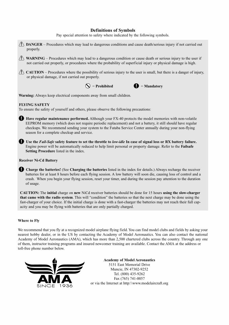
Definitions of SymbolsPay special attention to safety where indicated by the following symbols.
DANGER – Procedures which may lead to dangerous conditions and cause death/serious injury if not carried outproperly.
WARNING – Procedures which may lead to a dangerous condition or cause death or serious injury to the user if not carried out properly, or procedures where the probability of superficial injury or physical damage is high.
CAUTION – Procedures where the possibility of serious injury to the user is small, but there is a danger of injury, or physical damage, if not carried out properly.
= Prohibited = Mandatory
Warning: Always keep electrical components away from small children.
FLYING SAFETYTo ensure the safety of yourself and others, please observe the following precautions:
Have regular maintenance performed. Although your FX-40 protects the model memories with non-volatile EEPROM memory (which does not require periodic replacement) and not a battery, it still should have regular checkups. We recommend sending your system to the Futaba Service Center annually during your non-flyingseason for a complete checkup and service.
Use the Fail-Safe safety feature to set the throttle to low-idle In case of signal loss or RX battery failure.Engine power will be automatically reduced to help limit personal or property damage. Refer to the FailsafeSetting Procedure listed in the index.
Receiver Ni-Cd Battery
Charge the batteries! (See Charging the batteries listed in the index for details.) Always recharge the receiverbatteries for at least 8 hours before each flying session. A low battery will soon die, causing loss of control and a crash. When you begin your flying session, reset your timer, and during the session pay attention to the durationof usage.
CAUTION: The initial charge on new NiCd receiver batteries should be done for 15 hours using the slow-chargerthat came with the radio system. This will “condition” the batteries so that the next charge may be done using thefast-charger of your choice. If the initial charge is done with a fast-charger the batteries may not reach their full cap-acity and you may be flying with batteries that are only partially charged.
Where to Fly
We recommend that you fly at a recognized model airplane flying field. You can find model clubs and fields by asking yournearest hobby dealer, or in the US by contacting the Academy of Model Aeronautics. You can also contact the nationalAcademy of Model Aeronautics (AMA), which has more than 2,500 chartered clubs across the country. Through any oneof them, instructor training programs and insured newcomer training are available. Contact the AMA at the address or toll-free phone number below.
Academy of Model Aeronautics5151 East Memorial DriveMuncie, IN 47302-9252
Tel. (800) 435-9262Fax (765) 741-0057
or via the Internet at http:\\www.modelaircraft.org
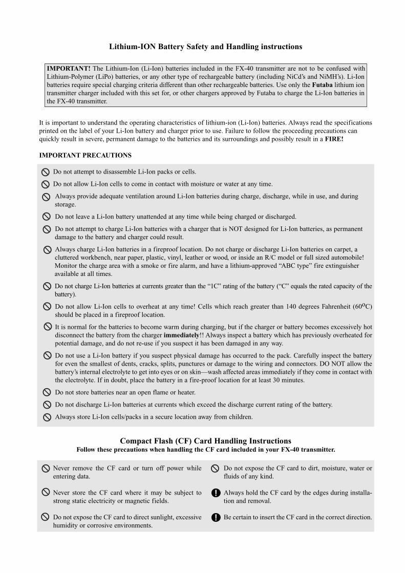
Lithium-ION Battery Safety and Handling instructions
It is important to understand the operating characteristics of lithium-ion (Li-Ion) batteries. Always read the specificationsprinted on the label of your Li-Ion battery and charger prior to use. Failure to follow the proceeding precautions can quickly result in severe, permanent damage to the batteries and its surroundings and possibly result in a FIRE!
IMPORTANT PRECAUTIONS
Do not attempt to disassemble Li-Ion packs or cells.
Do not allow Li-Ion cells to come in contact with moisture or water at any time.
Always provide adequate ventilation around Li-Ion batteries during charge, discharge, while in use, and during storage.
Do not leave a Li-Ion battery unattended at any time while being charged or discharged.
Do not attempt to charge Li-Ion batteries with a charger that is NOT designed for Li-Ion batteries, as permanent damage to the battery and charger could result.
Always charge Li-Ion batteries in a fireproof location. Do not charge or discharge Li-Ion batteries on carpet, a cluttered workbench, near paper, plastic, vinyl, leather or wood, or inside an R/C model or full sized automobile! Monitor the charge area with a smoke or fire alarm, and have a lithium-approved “ABC type” fire extinguisheravailable at all times.
Do not charge Li-Ion batteries at currents greater than the “1C” rating of the battery (“C” equals the rated capacity of thebattery).
Do not allow Li-Ion cells to overheat at any time! Cells which reach greater than 140 degrees Fahrenheit (60oC)should be placed in a fireproof location.
It is normal for the batteries to become warm during charging, but if the charger or battery becomes excessively hotdisconnect the battery from the charger immediately!! Always inspect a battery which has previously overheated forpotential damage, and do not re-use if you suspect it has been damaged in any way.
Do not use a Li-Ion battery if you suspect physical damage has occurred to the pack. Carefully inspect the batteryfor even the smallest of dents, cracks, splits, punctures or damage to the wiring and connectors. DO NOT allow thebattery’s internal electrolyte to get into eyes or on skin—wash affected areas immediately if they come in contact withthe electrolyte. If in doubt, place the battery in a fire-proof location for at least 30 minutes.
Do not store batteries near an open flame or heater.
Do not discharge Li-Ion batteries at currents which exceed the discharge current rating of the battery.
Always store Li-Ion cells/packs in a secure location away from children.
Compact Flash (CF) Card Handling InstructionsFollow these precautions when handling the CF card included in your FX-40 transmitter.
IMPORTANT! The Lithium-Ion (Li-Ion) batteries included in the FX-40 transmitter are not to be confused withLithium-Polymer (LiPo) batteries, or any other type of rechargeable battery (including NiCd’s and NiMH’s). Li-Ionbatteries require special charging criteria different than other rechargeable batteries. Use only the Futaba lithium iontransmitter charger included with this set for, or other chargers approved by Futaba to charge the Li-Ion batteries inthe FX-40 transmitter.
Never remove the CF card or turn off power whileentering data.
Never store the CF card where it may be subject tostrong static electricity or magnetic fields.
Do not expose the CF card to direct sunlight, excessivehumidity or corrosive environments.
Do not expose the CF card to dirt, moisture, water orfluids of any kind.
Always hold the CF card by the edges during installa-tion and removal.
Be certain to insert the CF card in the correct direction.

AT THE FLYING FIELD
Always pay particular attention to the flying fields’ rules, as well as the presence and location of spectators, the winddirection, and any obstacles on the field. Be very careful flying in areas near power lines, tall buildings, or communicationfacilities as there may be radio interference in their vicinity. If you must fly away from a club field, be sure there are no othermodelers flying within a three-to-five-mile range, or you may lose control of your aircraft or cause someone else to lose con-trol.
Before flying, be sure that the frequency you intend to fly with is not in use, and secure any frequency controldevice (pin, tag, etc.) for that frequency before turning on your transmitter. It is never possible to fly two or more mod-els on the same frequency at the same time. Even though there are different types of modulation (AM, FM, PCM), onlyone model may be flown on a single frequency at any one time.
Stop flying long before your batteries become low on charge. Do not rely on your radio’s low-battery warning sys-tems, which are intended only as a precaution, to tell you when to recharge. Always check your transmitter andreceiver batteries prior to each flight.
To prevent possible damage to your radio gear, turn the power switches on and off in the proper sequence:
1. Set the throttle stick to the idle position, or otherwise disarm your motor/engine.2. Fully extend the transmitter antenna.3. Turn on the transmitter power and allow your transmitter to reach its home screen. 4. Confirm the proper model memory has been selected.5. Turn on your receiver power.6. Test all controls. If a servo operates abnormally, don’t attempt to fly until you determine the cause of the problem. (For
PCM systems only: Test to ensure that the Failsafe settings are correct by waiting at least 2 minutes after adjusting then,turning the transmitter off and confirming the proper surface/throttle movements. Turn the transmitter back on.)
7. Start your engine.
9. After flying, bring your throttle stick to idle position, engage any kill switches or otherwise disarm your motor/engine.
10. Turn off receiver power.11. Turn off transmitter power.
If you do not turn on your system in this order, you may damage your servos or control surfaces, flood your engine, or inthe case of electric-powered or gasoline-powered models, the engine may unexpectedly turn on and cause a severe injury.
While you are getting ready to fly, if you place your transmitter on the ground, be sure that the wind won’t tipit over. If it is knocked over, the throttle stick may be accidentally moved, causing the engine to speed up. Also, dam-age to your transmitter may occur.
Before taxiing, be sure to extend the transmitter antenna to its’ full length. A collapsed antenna will reduce yourflying range and cause a loss of control. It is a good idea to avoid pointing the transmitter antenna directly at the model,since the signal is weakest in that direction.
Don’t fly in the rain! Water or moisture may enter the transmitter through the antenna or stick openings and causeerratic operation or loss of control. If you must fly in wet weather during a contest, be sure to cover your transmitterwith a waterproof barrier. Never fly if lightning is expected.
Never turn the transmitter off during flight! Switching the transmitter off and on during flight will very likely causea crash because of the time required for the transmitter to "reboot" and become fully functional.
8. Complete a full range check.
9<Before Use>
BEFORE USE FEATURES
PCMG3 (PCM Generation 3)PCMG3 has a 40% faster response than current PCM1024. The resolution is 2048, which is double
the current PCM1024. It can operate up to 14 Channels. The multi-level modulation technology has been implemented for the R/C industry to achieve the highest performance available today.
WindowsCEFX-40 utilizes the world famous Microsoft WindowsCE, which offers outstanding dependability and
valuable resources.
Color LCDFX-40 has a HVGA (640x240 pixels) wide screen full color LCD. It has a backlight and the screen is
Music Play
Voice Recording
Picture Image Pasting
you to download any image you like on your home screen.
Compact Flash
The memory size is 32 MB. Futaba prepares industrial rating CF cards.
WFSS (Wireless Frequency Setting System)The construction of both transmitter (FX-40) and receiver (R5014) are a frequency synthesizer system.
EditingThe touch panel and rotary encoder editing system will allow you to edit your model in the manner that
is easiest and most functional for you.
FunctionsThe internal dual processors operate the many FX-40 FEATURE functions and optimize the response
time. Most of the mixing functions are operated by curves which give you more precise settings.
10 <Before Use>
Stick
potentiometers also offer longer life.
Replaceable switches
position, and momentary etc.).
Li-ion batteryFX-40 is operated by 7.4V/5,000 mAh Lithium-Ion battery.
R5014DPSThe R5014DPS is a small 14CH synthesized receiver with high sensitivity and selectability.
Multi-Prop Decoder (Optional)The MPDX-1 multi-prop decoder connects to the receiver output of FX-40 System and expands the
signal of one channel to 8 channels.
11<Before Use>
Your FX-40 (packaged with a 14-channel PCM-G3 receiver) includes the following components:
• FX-40 Transmitter, including RF module (FX-FM)• R5014 Receiver• CFDP32M Data-Pack (CF card)• LT4F5000 Li-ion battery, LBC-2E5 Charger, FAD-1
AC adapter• Switch harness/DSC cord
• Accessory parts (Long lever head/Modification to ratchet system)
(The set contents depend on the type of set.)
Transmitter FX-40Operating system: 2-stick, 14 channels, PCM-G3,
synthesizer systemTransmitting frequency: US only 72 or 50 MHz bandsModula t ion: PCM-G3, PCM1024, or FM/PPM
switchable.Power supply: 7.4V LT4F5000 Li-ion batteryCurrent drain: 1 ampere maximum (RF power on and
back light on) 700mA averageReceiver R5014DPS(PCM-G3, Synthesizer, Dual conversion)Receiving frequency: US only 72 or 50 MHz bandsIntermediate freq.: 10.7 MHz & 450 kHzPower requirement: 4.8 V Ni-Cd batteryCurrent drain: 75 mASize: 52x37.5x16.5 mmWeight: 33 g.Channels: 14
Suggested Servos for use with your FX-40Servo S9154 (Digital servo)Control system: Pulse width control, 1.52 ms neutralPower requirement: 4.8 V (from receiver)Output torque: 63.9 oz.-in. (4.6 kg-cm) at 4.8VOperating speed: 0.14 sec/60 at 4.8VSize: 1.87 x 1.06 x 0.97 in. (47.5 x 27.0 x 25.3 mm)Weight: 1.87 oz. (53 g)Servo S9151 (Digital servo)Control system: Pulse width control, 1.52 ms neutralPower requirement: 4.8 V (from receiver)Output torque: 131.9 oz.-in. (9.5 kg-cm) at 4.8VOperating speed: 0.19 sec/60 at 4.8VSize: 1.57 x 0.79 x 1.44 in. (40.0 x 20.0 x 36.6 mm)Weight: 1.79 oz. (50 g)Servo S9250 (Digital servo)Control system: Pulse width control, 1.52 ms neutralPower requirement: 4.8 V (from receiver)Output torque: 76.4 oz.-in. (5.5 kg-cm) at 4.8VOperating speed: 0.11 sec/60 at 4.8VSize: 1.59 x 0.79 x 1.48 in. (40.5 x 20.0 x 37.5 mm)Weight: 1.90 oz. (54 g)Servo S9255 (Digital servo)Control system: Pulse width control, 1.52 ms neutralPower requirement: 4.8 V (from receiver)Output torque: 125.0 oz.-in. (9.0 kg-cm) at 4.8VOperating speed: 0.16 sec/60 at 4.8VSize: 1.57 x 0.79 x 1.44 in. (40.0 x 20.0 x 36.6 mm)Weight: 1.94 oz. (55 g)

12 <Before Use>
• Compact Flash Memory card - CFDP 32M Data-Pack increases your model, music file, voice file, and picture image file storage capability, and allows you to transfer model settings to another FX-40 transmitter.
• LT4F5000 Transmitter battery pack - the (5000mAh) transmitter Li-ion battery pack may be easily
• Trainer cord - the optional training cord may be used to help a beginning pilot learn to fly easily by placing the instructor on a separate transmitter. Note that the FX-40 transmitter may be connected to another FX-40 system, as well as to any other models of Futaba transmitters. The FX-40 transmitter uses the newer “Micro” rectangular type cord plug. Both Micro- to-Micro and Micro-to-round plug style trainer cords are available.
version with heavier wire, are available to aid in your larger model and other installations.
• Gyros - a variety of genuine Futaba gyros are available for your aircraft or helicopter needs.
head speed regardless of blade pitch, load, weather, etc.
• DSC Cord - allows setup and testing without transmitting. With your Transmitter and Receiver off, plug cord into trainer port then, into the receiver Battery/DSC (B/C) slot. All programming and setup may be done in this manner without transmitting.
• Receivers - various models of Futaba receivers may be purchased for use in other models. (Receivers for PCM-G3, PCM1024, or FM/PPM types are available.)
The following additional accessories are available from your dealer. Refer to a Futaba catalog for more information:
13<Before Use>
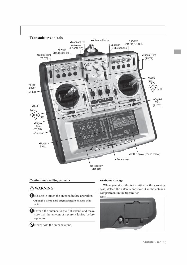
Transmitter controls
Cautions on handling antenna
WARNING
Be sure to attach the antenna before operation.*Antenna is stored in the antenna storage box in the trans-
mitter.
Extend the antenna to the full extent, and make sure that the antenna is securely locked before operation.
Never hold the antenna alone.
•Antenna storageWhen you store the transmitter in the carrying
case, detach the antenna and store it in the antenna compartment in the transmitter.
(J1)
(J2)
(J4)
(J3)

14 <Before Use>
•Angle adjustment of the antenna
you like. Use 2.5mm hexagonal wrench to turn counterclockwise to release the screw on the left of the antenna holder, and change the angle of the antenna as you like, then retighten.
LED monitorThe color of the FX-40 logo mark shows the
status of the transmitter.(LED Display)
• When you turn on the transmitter, FX-40 logo shows different colors, and then the color stays constantly pink. The FX-40 logo blinks yellow very rapidly while internal processing is carried out after the power is turned on. Once the internal processing is over, the logo turns to pink color.
• The FX-40 logo blinks blue slowly when No is selected for transmit.
• The FX-40 logo turns on blue when you use DSC cable or when the trainer function is set at student's side.
• The FX-40 logo blinks red slowly when you attach the RF module that is different from the setting.
• Under the normal usage (radio wave is being emitted), the FX-40 logo turns on green.
Precautions when opening the rear cover and working inside
When opening the rear cover and performing
other work inside the transmitter, open the rear cover as described below. Also, always observe the precautions.1. Turn off the power to the transmitter.
rear cover.
Fixing screws
3. Remove the battery stopper by pulling it forward while pushing the lock button in the
Battery stopperBattery
CAUTION
When the rear cover is opened, always remove the battery before performing switch replacement or other work.
while performing work may cause a short circuit and dam-age the transmitter.
4. Replace the switch, etc. (Refer to each work item.)
CAUTION
Be careful not to damage the internal PC board
Be careful not to touch the protruding parts of the switch and PC board.
5. At the end of work, reload the battery and fasten it with the battery stopper.
6. After fitting the antenna side of the rear cover, align the front side of the cover with the groove in the rear case and close the cover.
Switch reallocation
like.(Default settings)
• SA : 3 positions; Alternate; Short lever• SB : 3 positions; Alternate; Short lever• SC : 3 positions; Alternate; Long lever• SD : 3 positions; Alternate; Short lever• SE : 3 positions; Alternate; Short lever• SF : 2 positions; Alternate; Long lever• SG : 3 positions; Alternate; Short lever• SH : 3 positions; Alternate; Short lever
setting screen of the function menu.

15<Before Use>
[Replacement]1. Turn off the power to the transmitter and
then use the switch ornamental nut j ig
ornamental nut.
2. Open the rear cover, and remove the battery.
(See [Precautions when opening the rear cover and working inside].)
3. Disconnect the connector of the switch you want to replace.
*The photo below is a view with switch A(SA) removed.
4. Use the ornamental nut to install the switch removed from another posit ion, or an optional switch, to the switch mounting hole by the reverse procedure of the above.
5. Connect the connector.
[Connector wiring color]
6. Install the battery and then close the rear cover.
(See the preceding item.)7. Change the setting at the [Important] System
menu switch setting window to match the type of the new switch.
Volume
Locked state
Volume LD, CD, and RD:If you push the volume (LD or RD) to the
bottom, the volume will stay there. If you push the volume again, the lock will be released and become operative again.
This volume (CD) is digital type (rotary encoder). This volume works as both a volume and a push-switch.
*FX-40 beeps when the volume knob reaches center.
screen in the Linkage menu.
Slide Lever
L3 L2 L1
L1 (right side), L2 (center), L3 (left side):A click will be felt at the center of slide lever
operation.*It sounds when the lever comes to the center.
in the linkage menu.
on the setting screen of mixing functions.
16 <Before Use>
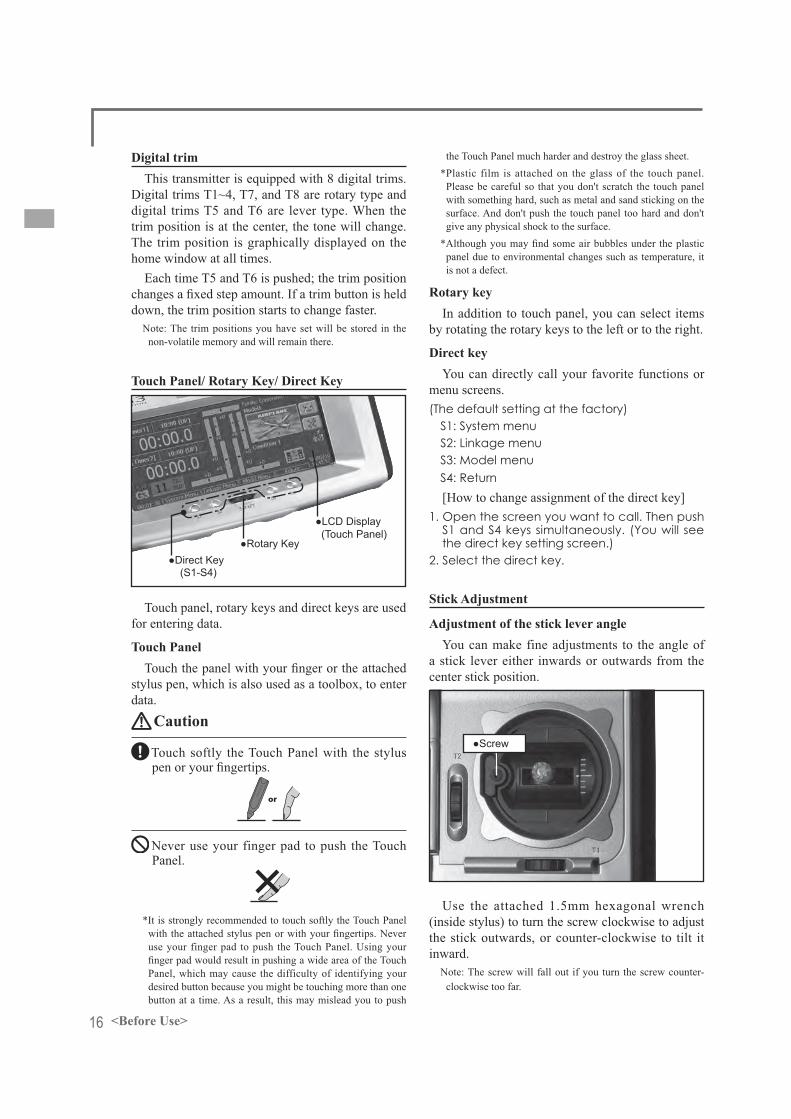
Digital trimThis transmitter is equipped with 8 digital trims.
Digital trims T1~4, T7, and T8 are rotary type and digital trims T5 and T6 are lever type. When the trim position is at the center, the tone will change. The trim position is graphically displayed on the home window at all times.
Each time T5 and T6 is pushed; the trim position
down, the trim position starts to change faster.Note: The trim positions you have set will be stored in the
non-volatile memory and will remain there.
Touch Panel/ Rotary Key/ Direct Key
Touch panel, rotary keys and direct keys are used for entering data.
Touch Panel
stylus pen, which is also used as a toolbox, to enter data.
Caution
Touch softly the Touch Panel with the stylus
or
Never use your finger pad to push the Touch Panel.
*It is strongly recommended to touch softly the Touch Panel
use your finger pad to push the Touch Panel. Using your
Panel, which may cause the difficulty of identifying your desired button because you might be touching more than one button at a time. As a result, this may mislead you to push
the Touch Panel much harder and destroy the glass sheet.*Plastic film is attached on the glass of the touch panel.
Please be careful so that you don't scratch the touch panel with something hard, such as metal and sand sticking on the surface. And don't push the touch panel too hard and don't give any physical shock to the surface.
panel due to environmental changes such as temperature, it is not a defect.
Rotary keyIn addition to touch panel, you can select items
by rotating the rotary keys to the left or to the right.
Direct key
menu screens.(The default setting at the factory)
S1: System menuS2: Linkage menuS3: Model menuS4: Return[How to change assignment of the direct key]
1. Open the screen you want to call. Then push S1 and S4 keys simultaneously. (You will see the direct key setting screen.)
2. Select the direct key.
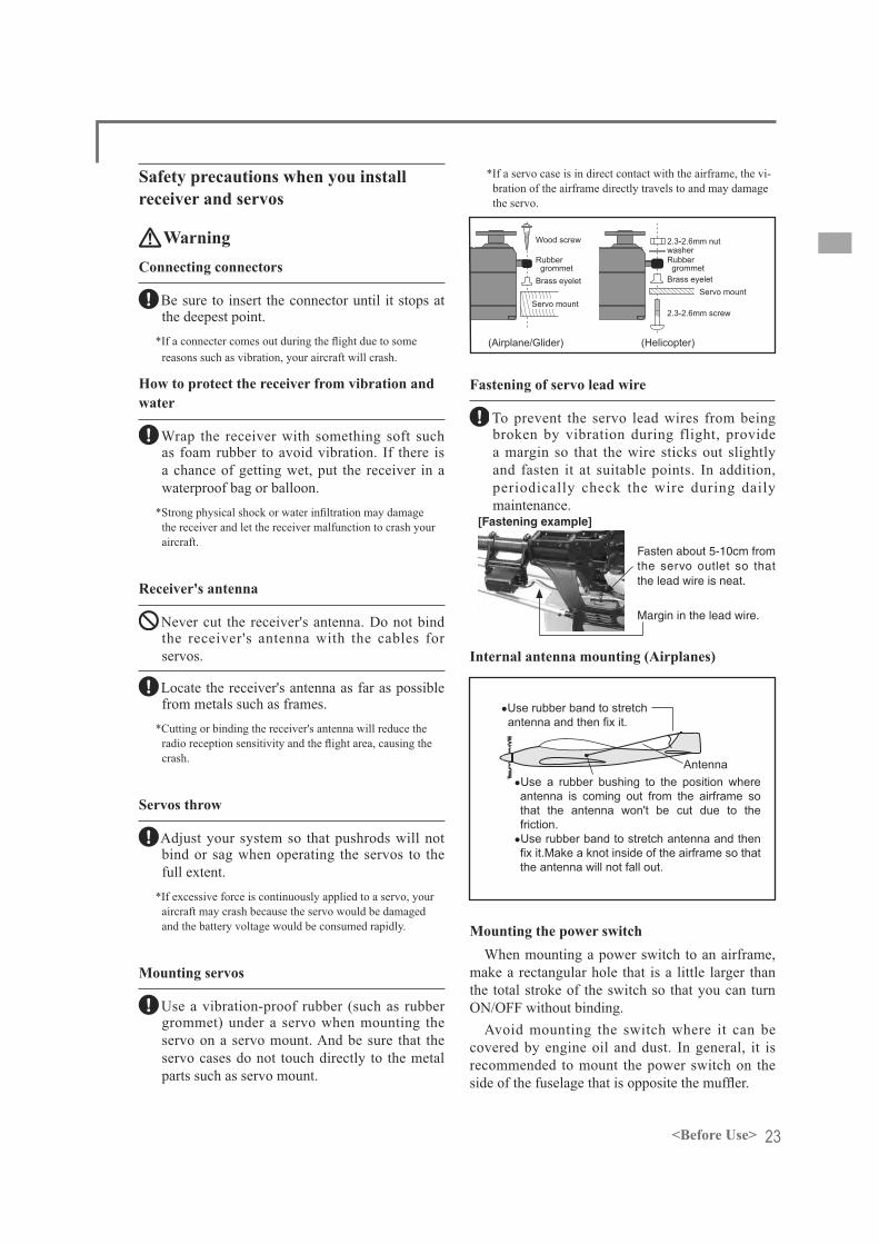
Stick Adjustment
Adjustment of the stick lever angle
a stick lever either inwards or outwards from the center stick position.
Use the attached 1.5mm hexagonal wrench
the stick outwards, or counter-clockwise to tilt it inward.
Note: The screw will fall out if you turn the screw counter-clockwise too far.

17<Before Use>
A long lever head is supplied with this set. Use it to replace the lever head, as you like. The length of the stick lever head can also be changed.
Lever headA
Lever headB
[How to adjust the length]1. Hold the lever head "B" and turn the lever
head "A" counter-clockwise, the lock will be released.
2. Turn the lever-head "A" clockwise as you hold the lever-head "B" after placing it as you like.
Stick lever tension adjustmentThe tension of the self-return type stick levers
[Tension adjustment]1. Turn off the power to the transmitter.2. Open the rear cover and remove the
battery. (See [Precautions when opening the rear cover and working inside].)
to turn the adjusting screw of the stick you want to adjust and set it as your prefer.*Turning the screw clockwise increases the tension.
4. At the end of adjustment, install the battery and close the rear cover. (See [Precautions when opening the rear cover and working inside].)
When modifying the throttle stick from self-neutral system (factory installation) to ratchet system, use the accessory parts to change the corresponding switch to the mode (Mode 1 or Mode 2) used.
1. Turn off the power to the transmitter.2. Open the rear cover and remove the
battery. (See [Precautions when opening the rear cover and working inside].)
[Mode 1] Tension adjusting screw*This screw is removed.Swing arm
(2x6mm)(Accessory)
(Accessory)
to remove the tension adjusting screw.*This screw is used only when returning to the self-neutral
system. (Save it.)
4. Fasten the accessory swing arm stopper with the set screw as shown in the photo above. This frees the throttle stick.*Lock the stick at the low side or high side by some method
so that the stick swing arm does not rise when installing the stopper.
*Insert the stopper so that the swing arm is not returned by the spring. Align the notch of the stopper to the spring.
[Gripping force adjustment]
For helicopters
For airplanes
to turn the adjusting screw and set it as you prefer. Turning the adjusting screw clockwise increases the gripping force.
*Free state when shipped from the factory.*This transmitter is equipped with two ratchet plates, one for
airplane and the other one for helicopter. If you tighten both
*If you want to change the setting from airplane to helicopter (or from helicopter to airplane), turn the currently set screw counterclockwise until the throttle stick moves freely. The turn the screw your want to set clockwise until you get the tension you like.
6. After modification, install the battery and close the rear cover. (See [Precautions when opening the rear cover and working inside].)

18 <Before Use>
CF Card CFDP32M
such as model data, music, sound and pictures. Its memory size is 32MB.
Warning
Be sure to turn off the power to the transmitter before inserting or removing the CF card.
As the CF card is a precision device, do not use excessive force when inserting.
Be sure to use only Futaba's original CF card, CFDP32M, for the T14MZ transmitter.
* Futaba does not recommend any CF cards other than Futaba's original CF cards.
CF card insertion/removal1. Turn off the power to the transmitter and
open the cover at the right side of the transmitter.
2. Insert or remove the CF card.
[Card insertion]
(1) Open the cover in the arrow direction.
(2) Insert the CF card in the direction shown in the photo.
Cover
(3) Push in the CF card.
Eject button
*Turn the CF card so that the front of the card faces the back of the transmitter. Then slide the card into the slot.
*Insert the card into the slot until it touches bottom. At the
[Card removal]
CF card is pushed out.
(1) Push the eject button.
and can be removed.
3. Close the cover.
Read data from a PC
transmitter. Equipment for reading and writing CF cards are available at most electronics stores.
[Important]Before saving data from the PC, insert the CF
card into the transmitter and turn on the power. To
*Use only CF card reader/writer that complies with CFA (CompactFlashTM Association) standard.
Stored dataThe life of the CF card is limited due to the use
of Flash memory. When you have a problem of saving or reading data such as picture data after a long period of use, please get a new CF card.
*We do not have the responsibility of compensating any failure or damage to the data stored in the memory card no matter what the reason is. Be sure to keep the backup of your important data in your CF card.
*No necessity for backup; FX-40 transmitters and CF cards are using nonvolatile memory devices so that the data stored in those will not be destroyed even without a backup battery. The clock for the transmitter depends on the Lithium battery.

19<Before Use>
Connector/Plug
Connector for trainer function (TRAINER)When you use trainer function, connect the
optional trainer cable between the transmitters for teacher and student.
screen in the System menu.
Connector for DSC function (DSC)
transmitting radio waves by connecting the transmitter and the receiver to the DSC cable.
*Please refer to the section "Connection between Receiver/Servo"
Audio plug (PHONE)Connecting a stereo headphone to this plug, you
Connector for battery charger (CHG)
Battery Charge (CHG)
This is the connector for charging the Lithium Ion battery LT4F5000 that is installed in the transmitter. Do not use any other chargers except LBC-2E5 or CR-2500 that is for 12V application to charge the LT4F5000 battery through this connector.
Danger
Do not connect any other chargers except LBC-2E5 or CR-2500 to this charging connector.
USB port (Transmitter right side)*This is for factory use only.
USB port

20 <Before Use>
Installing and Removing of the battery LT4F5000 for the transmitter
Installing the battery1. Open the rear cover. (See [Precautions when
opening the rear cover and working inside and working inside].)
2. Remove the battery stopper by pulling it forward while pushing the lock button in the arrow direction.
3. Install the battery by sliding it in the horizontal direction.
4. Fasten the battery by re-installing the battery stopper.
Battery stopperBattery
5. Close the rear cover. (See [Precautions when opening the rear cover and working inside].)
Removing the batteryWhen removing the battery, always turn off the
power to the transmitter. If the battery is removed while power to the transmitter is on, the set data will not be saved.1. Turn off the power to the transmitter.2. Open the rear cover. (See [Precautions when
opening the rear cover and working inside].)3. Remove the battery stopper by pulling it
forward while pushing the lock button in the arrow direction. Then remove the battery by sliding it horizontally
Battery stopperBattery
Warning
Be careful to not drop the battery.
Never take out the battery from the FX-40 transmitter while the LED monitor is blinking yellow after turning off the power the FX-40 transmitter.
* Internal devices such as memories may have been de-stroyed.
* If there is any problem, the message "Backup Error" will be shown the next time when you turn on the power of the transmitter. Do not use the transmitter as it is, send it back for a check to the Futaba Service Center.

21<Before Use>
RF module FX-FMTo change the frequency band, use the FX-FM
module which is sold separately.
RF module
CAUTION
Turn off the power to the transmitter before you remove or install the module.
Removing the RF module1. Turn off the power to the transmitter.2. Open the rear cover. (See [Precautions when
opening the rear cover and working inside].)3. Grip the tabs at the left and right sides of the
module and pull the module straight out.*There are two connectors; one at the top and one at the
bottom. If the module is not pulled out straight, it will be
Installing the RF module1. Insert the module until it bottoms while being
careful not to bend the pins of the transmitter side connector.
Toolbox
Hexagonal wrench (1.5mm and 2.5mm)
antenna.
Tool for removing ornamental nutsThis is for replacement of switches.
Stylus pen
may use this tool as a stylus pen for operating the touch panel. This stylus pen can let you do more precise operation than fingers without damaging the surface.

22 <Before Use>
Receiver nomenclatureBefore using the receiver, be sure to read the
precautions listed in the following pages.
Receiver R5014DPS
Antenna
Connectors
~
Connector"1 through 12": outputs for the channels 1 through 12"DG1", "DG2": outputs of DG1 and DG2 channels "B/C": connector for the power and DSC.
LED Monitor This monitor is used to check the frequency
change of the receiver.
23<Before Use>
Safety precautions when you install receiver and servos
WarningConnecting connectors
Be sure to insert the connector until it stops at the deepest point.
reasons such as vibration, your aircraft will crash.
How to protect the receiver from vibration and water
Wrap the receiver with something soft such as foam rubber to avoid vibration. If there is a chance of getting wet, put the receiver in a waterproof bag or balloon.
the receiver and let the receiver malfunction to crash your aircraft.
Receiver's antenna
Never cut the receiver's antenna. Do not bind the receiver's antenna with the cables for servos.
Locate the receiver's antenna as far as possible from metals such as frames.
*Cutting or binding the receiver's antenna will reduce the
crash.
Servos throw
bind or sag when operating the servos to the full extent.
*If excessive force is continuously applied to a servo, your aircraft may crash because the servo would be damaged and the battery voltage would be consumed rapidly.
Mounting servos
Use a vibration-proof rubber (such as rubber grommet) under a servo when mounting the servo on a servo mount. And be sure that the servo cases do not touch directly to the metal parts such as servo mount.
*If a servo case is in direct contact with the airframe, the vi-bration of the airframe directly travels to and may damage the servo.
Rubber grommetBrass eyelet
Wood screw
Servo mount
2.3-2.6mm nutwasherRubber grommetBrass eyelet
Servo mount
2.3-2.6mm screw
(Helicopter)(Airplane/Glider)
Fastening of servo lead wire
To prevent the servo lead wires from being broken by vibration during flight, provide a margin so that the wire sticks out slightly and fasten it at suitable points. In addition, periodically check the wire during daily maintenance.
[Fastening example]
Fasten about 5-10cm from the servo outlet so that the lead wire is neat.
Margin in the lead wire.
Internal antenna mounting (Airplanes)
Use rubber band to stretch antenna and then fix it.
AntennaUse a rubber bushing to the position where antenna is coming out from the airframe so that the antenna won't be cut due to the friction.Use rubber band to stretch antenna and then fix it.Make a knot inside of the airframe so that the antenna will not fall out.
Mounting the power switch When mounting a power switch to an airframe,
make a rectangular hole that is a little larger than the total stroke of the switch so that you can turn ON/OFF without binding.
Avoid mounting the switch where it can be covered by engine oil and dust. In general, it is recommended to mount the power switch on the
24 <Basic Operation>
BASIC OPERATION
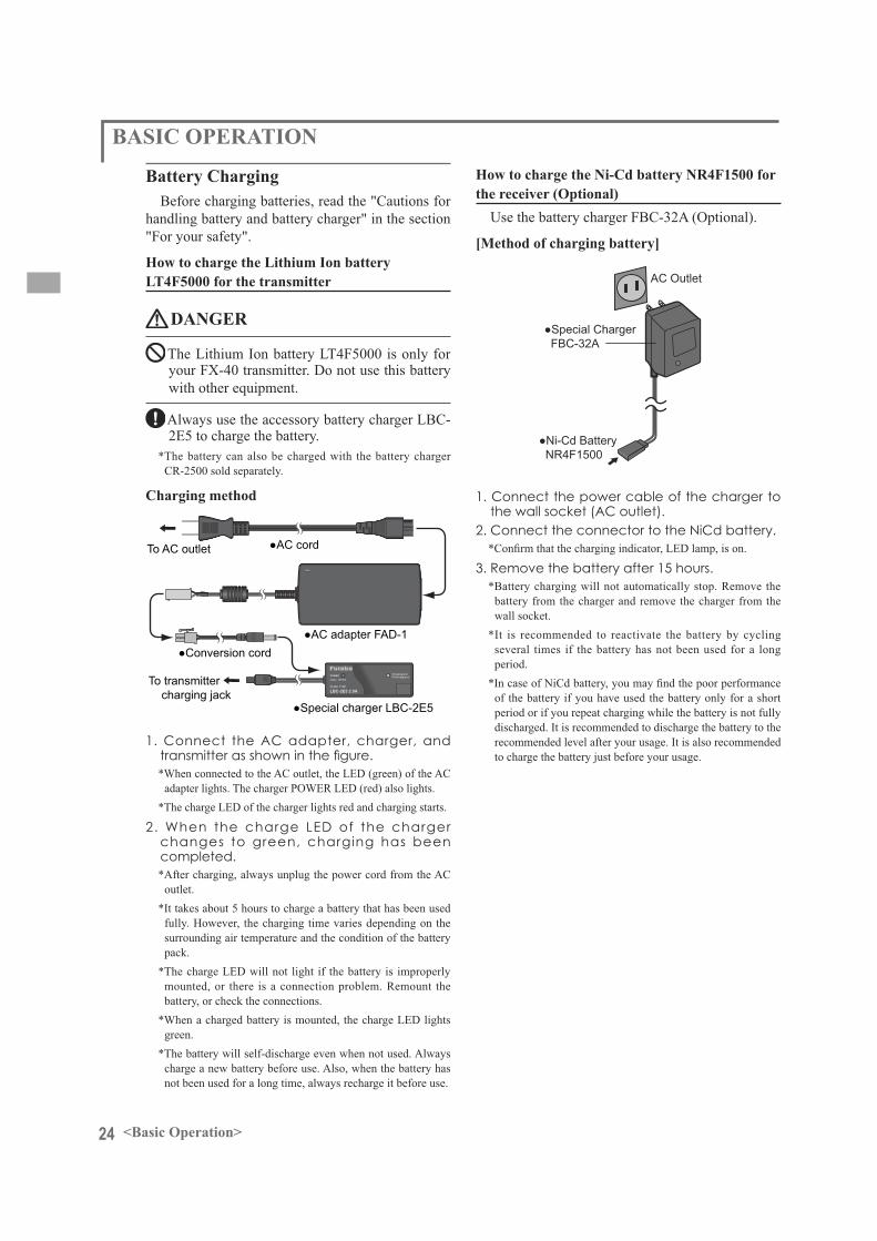
Battery ChargingBefore charging batteries, read the "Cautions for
handling battery and battery charger" in the section "For your safety".
How to charge the Lithium Ion battery LT4F5000 for the transmitter
DANGER
The Lithium Ion battery LT4F5000 is only for your FX-40 transmitter. Do not use this battery with other equipment.
Always use the accessory battery charger LBC-2E5 to charge the battery.
*The battery can also be charged with the battery charger CR-2500 sold separately.
Charging method
To AC outlet
1. Connect the AC adapter, charger, and
*When connected to the AC outlet, the LED (green) of the AC adapter lights. The charger POWER LED (red) also lights.
*The charge LED of the charger lights red and charging starts.
2. When the charge LED of the charger changes to green, charging has been completed.*After charging, always unplug the power cord from the AC
outlet.*It takes about 5 hours to charge a battery that has been used
fully. However, the charging time varies depending on the surrounding air temperature and the condition of the battery pack.
*The charge LED will not light if the battery is improperly mounted, or there is a connection problem. Remount the battery, or check the connections.
*When a charged battery is mounted, the charge LED lights green.
*The battery will self-discharge even when not used. Always charge a new battery before use. Also, when the battery has not been used for a long time, always recharge it before use.
How to charge the Ni-Cd battery NR4F1500 for the receiver (Optional)
Use the battery charger FBC-32A (Optional).
[Method of charging battery]
AC Outlet
1. Connect the power cable of the charger to
2. Connect the connector to the NiCd battery.
*Battery charging will not automatically stop. Remove the battery from the charger and remove the charger from the wall socket.
*It is recommended to reactivate the battery by cycling several times if the battery has not been used for a long period.
of the battery if you have used the battery only for a short period or if you repeat charging while the battery is not fully discharged. It is recommended to discharge the battery to the recommended level after your usage. It is also recommended to charge the battery just before your usage.
25<Basic Operation>
How to turn ON/OFF the power of the transmitter
Windows® CE is installed as a built-in operating system in the FX-40 transmitter. Compared to the conventional system, the FX-40 takes extra time for internal processing when it is turned on/off. For safety reasons, the radio will be emmiting
turning on the power. Please follow the instructions for turning on/off the transmitter.
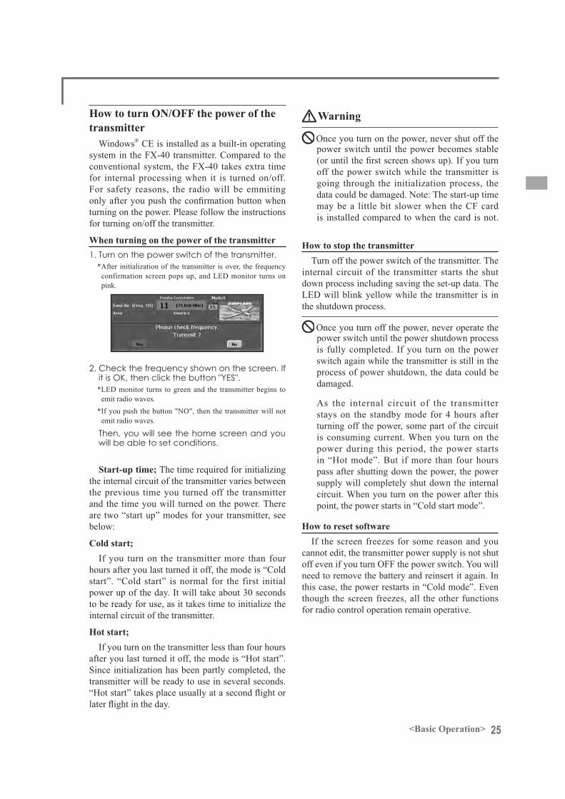
When turning on the power of the transmitter
*After initialization of the transmitter is over, the frequency confirmation screen pops up, and LED monitor turns on pink.
*LED monitor turns to green and the transmitter begins to emit radio waves.
*If you push the button "NO", then the transmitter will not emit radio waves.
will be able to set conditions.
Start-up time; The time required for initializing the internal circuit of the transmitter varies between the previous time you turned off the transmitter and the time you will turned on the power. There are two “start up” modes for your transmitter, see below:
Cold start;If you turn on the transmitter more than four
hours after you last turned it off, the mode is “Cold start”. “Cold start” is normal for the first initial power up of the day. It will take about 30 seconds to be ready for use, as it takes time to initialize the internal circuit of the transmitter.
Hot start;If you turn on the transmitter less than four hours
after you last turned it off, the mode is “Hot start”. Since initialization has been partly completed, the transmitter will be ready to use in several seconds.
Warning
Once you turn on the power, never shut off the power switch until the power becomes stable
off the power switch while the transmitter is going through the initialization process, the data could be damaged. Note: The start-up time may be a little bit slower when the CF card is installed compared to when the card is not.
How to stop the transmitterTurn off the power switch of the transmitter. The
internal circuit of the transmitter starts the shut down process including saving the set-up data. The LED will blink yellow while the transmitter is in the shutdown process.
Once you turn off the power, never operate the power switch until the power shutdown process is fully completed. If you turn on the power switch again while the transmitter is still in the process of power shutdown, the data could be damaged.
As the internal circuit of the transmitter stays on the standby mode for 4 hours after turning off the power, some part of the circuit is consuming current. When you turn on the power during this period, the power starts in “Hot mode”. But if more than four hours pass after shutting down the power, the power supply will completely shut down the internal circuit. When you turn on the power after this point, the power starts in “Cold start mode”.
How to reset softwareIf the screen freezes for some reason and you
cannot edit, the transmitter power supply is not shut off even if you turn OFF the power switch. You will need to remove the battery and reinsert it again. In this case, the power restarts in “Cold mode”. Even though the screen freezes, all the other functions for radio control operation remain operative.
26 <Basic Operation>
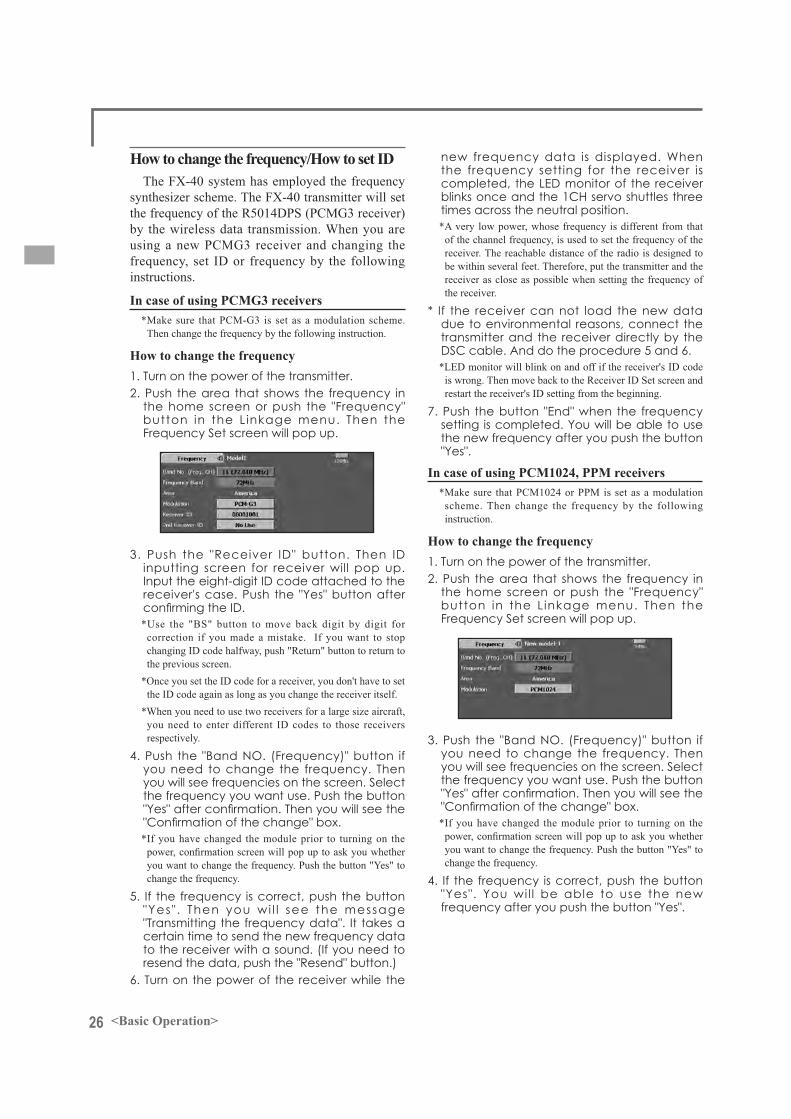
How to change the frequency/How to set IDThe FX-40 system has employed the frequency
synthesizer scheme. The FX-40 transmitter will set the frequency of the R5014DPS (PCMG3 receiver) by the wireless data transmission. When you are using a new PCMG3 receiver and changing the frequency, set ID or frequency by the following instructions.
In case of using PCMG3 receivers*Make sure that PCM-G3 is set as a modulation scheme.
Then change the frequency by the following instruction.
How to change the frequency
*Use the "BS" button to move back digit by digit for correction if you made a mistake. If you want to stop changing ID code halfway, push "Return" button to return to the previous screen.
*Once you set the ID code for a receiver, you don't have to set the ID code again as long as you change the receiver itself.
*When you need to use two receivers for a large size aircraft, you need to enter different ID codes to those receivers respectively.
*If you have changed the module prior to turning on the
you want to change the frequency. Push the button "Yes" to change the frequency.
completed, the LED monitor of the receiver
*A very low power, whose frequency is different from that of the channel frequency, is used to set the frequency of the receiver. The reachable distance of the radio is designed to be within several feet. Therefore, put the transmitter and the receiver as close as possible when setting the frequency of the receiver.
transmitter and the receiver directly by the
*LED monitor will blink on and off if the receiver's ID code is wrong. Then move back to the Receiver ID Set screen and restart the receiver's ID setting from the beginning.
In case of using PCM1024, PPM receivers*Make sure that PCM1024 or PPM is set as a modulation
scheme. Then change the frequency by the following instruction.
How to change the frequency
*If you have changed the module prior to turning on the
you want to change the frequency. Push the button "Yes" to change the frequency.

27<Basic Operation>
Registration of the user's nameFX-40 transmitter can register user's name.
How to register user's name
space key
(If you want to protect the user's name)If you don't want anybody else to change your
user's name, set your ID in the following way.*Please be aware that you will not able to change user's name
if you forget your password.
screen.
*Even if you enter the same character, your password will be identified differently depending on whether you are using "Transform" mode or "Direct" mode for inputting.
28 <Basic Operation>
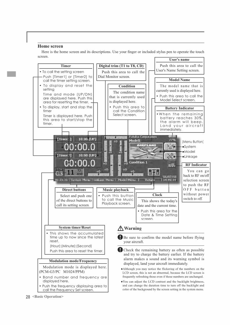
Timer• To call the setting screen
call the timer setting screen.• To display and reset the
setting
area for resetting the timer.• To display, start and stop the
timer
timer.
Warning
Be sure to confirm the model name before flying your aircraft.
Check the remaining battery as often as possible and try to charge the battery earlier. If the battery alarm makes a sound and its warning symbol isdisplayed, land your aircraft immediately.
LCD screen, this is not an abnormal, because the LCD screen is frequently refreshing those even if those numbers are unchanged.
and can change the duration time to turn off the backlight and color of the background by the screen setting in the system menu.
Home screen
Digital trim (T1 to T8, CD)Push this area to call the
Dial Monitor screen.
ConditionThe condition name
that is currently used is displayed here.
call the Condition
ClockThis shows the today's
date and the current time.
screen.
Model NameThe mode l name tha t i s
currently used is displayed here.
User's namePush this area to call the
User's Name Setting screen.
Modulation mode/FrequencyModulation mode is displayed here.
(PCM-G3/PC M1024/PPM)
displayed here.
System timer/Reset
reset.
Direct buttonsSelect and push one
of the direct buttons to call its setting screen.
Music playback
Playback screen.
screen.
Battery Indicator• W h e n t h e r e m a i n i n g
battery reaches 30%,the a la rm wi l l beep.
immediately.
RF IndicatorYo u c a n g o
back to RF on/off selection screen to push the RF O F F b u t t o nwithout power switch to off.
29<Basic Operation>
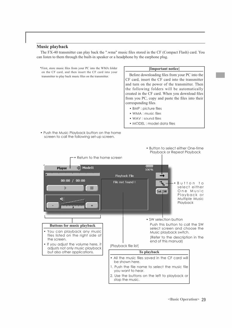
Music playback
can listen to them through the built-in speaker or a headphone by the earphone plug.
on the CF card, and then insert the CF card into your [Important notice]
CF card, insert the CF card into the transmitter and turn on the power of the transmitter. Then the following folders will be automatically
Playback or Repeat Playback
se lect e i ther
P l a y b a c k o r
Playback
select screen and choose the
(Refer to the description in the
Buttons for music playback
files listed on the right side of the screen.
To playback
be shown here.

30 <System Menu>
SYSTEM MENU
System Menu functions table[Trainer]: Starts and sets the trainer system.[Display]: Display adjustment and auto power off setting.[Date & Time]: Sets the date and time (system clock setting) and resets the timer.[User Name]: User name registration and ID Pin number.[Switch]: Toggle switch type setting (Set when the switch is replaced.)[H/W Setting]: Hardware reverse and Stick setting.[Information]: Displays the program version, CF card information, and product ID.
The System Menu sets up functions of thetransmitter, this does not set up any model data.

31<System Menu>
Trainer Trainer system starting and setting
FX-40 trainer system makes it possible to chose which channels and operation modes are to be used at the instructor's transmitter. Because the switchand rate of each channel can be set, the training method can also be matched to the student's skilllevel. Two transmitters must be connected by an optional Trainer Cord, and the Instructors’transmitter should be programmed for trainer operation, as described below.
When the Instructor activates the trainer switch, the student has control of the aircraft (if MIX or FUNC mode is turned on, the Instructor can makecorrections while the student has control). When the switch is released the Instructor regains control. This is very useful if the student gets the aircraft into an undesirable situation.
NOTE: This trainer system can be used in the following manner;
1. In the FX-40 transmitter and a conventional transmitter, if the channel order is different. It is necessary to match the channel order in the Function Menu when connecting it with other than a FX-40.
2. When the T14MZ is used as the Teacher, set the modulation mode of the student’s transmitter to PPM. If being used as the student, set the FX-40 to the modulation
When the Instructors’ transmitter is a T14MZ, FX-40, 12Z, T9Z, T9C or T7C transmitter, it should be switched to PPM mode.
3. Be sure that all channels work correctly in
(The display screen is an example. The screen depends on the model type.)
Corresponding types of transmitters:
Non-corresponding types of transmitters:

32 <System Menu>
Student mode
Teacher mode
"NORM" mode (Normal mode);
"MIX" mode;
"FUNC" mode (Function mode);
[Notes]1. In the teacher mode, the trainer function
display does not come on as long as thestudent's transmitter is not receiving signalsfrom the teacher's transmitter (when thestudent's transmitter is not connected).

33<System Menu>
LCD contrast adjustment
*When the right side button is pressed, the LCD contrast decreases. When the left side button is pressed, the LCD contrast increases.
Auto power off time setting
*When the time the transmitter is inactive exceeds the set time, the power is turned off automatically. This time can beset up to 1 hour in 10 minutes increments. The auto power off function can also be deactivated.
Backlighting brightness adjustment
*When the right side button is touched, the backlightingbecomes brighter. When the left side button is touched, the backlighting becomes darker.
Backlight power-off time
DisplayThe following LCD screen adjustments and auto
power off setting are possible:
*The backlight consumes a large amount of power. We recommend you to turn off the backlight by setting the backlight power-off time to about one minute.
Background color
*There are four background colors.
Touch panel calibration
*In ordinary operation, this calibration is not necessary. If you notice the touch panel is not functioning correctly after long use, we recommend you to carry out this calibration.
34 <System Menu>
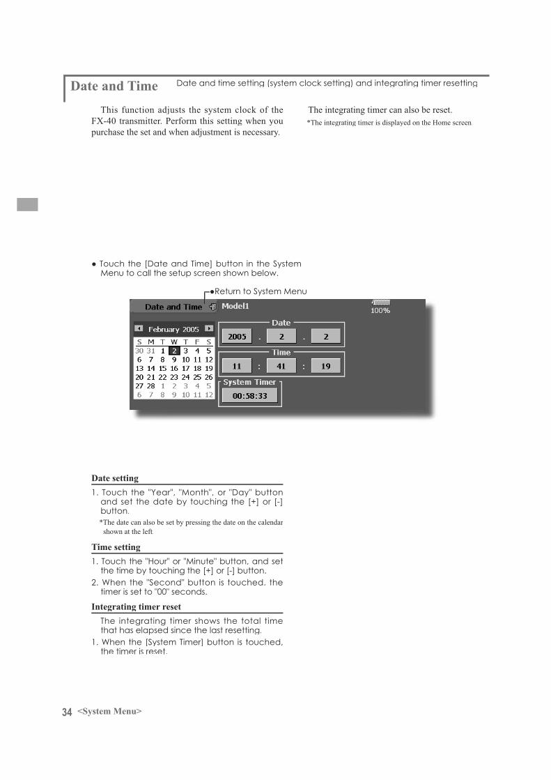
Date setting
*The date can also be set by pressing the date on the calendar shown at the left.
Time setting
Integrating timer reset
Date and TimeThis function adjusts the system clock of the
FX-40 transmitter. Perform this setting when youpurchase the set and when adjustment is necessary.
The integrating timer can also be reset.*The integrating timer is displayed on the Home screen.

35<System Menu>
User Name This function registers the FX-40 user name.A PIN can also be set to protect the data or user
name.
*Set the PIN carefully. When a system PIN is set, if youforget the PIN, none of the settings can be changed. In this case, the system must be reset by the Futaba Service Center.
User name registration
*A user name of up to 32 characters can be entered. *The set user name is displayed on the Home screen.(For a detailed description of the input method, see [User
Name Registration/Character Input Method] in the BasicOperation section.)
User name or set data protection
*User Name: Select when you want to protect the user name only.
*System: Select when you want to protect all the set data.
*When a PIN is set at the user name, it must be entered the next time the User Name screen is opened.When a System PIN is set, a button displaying a key icon appears on the Home screen.When you want to change the setting, touch this button and enter the PIN.

36 <System Menu>
Switch selection
2/3 position selection
SwitchIf you modify the location of the switches on the
right and left (top) of the transmitter, you should be sure to re-assign functions to the switches for proper operation.
A “Lock” is included to prevent settings from being modified by mistake. When you need to change settings, unlock this by pressing “Lock” it will then read ”Unlock” and you can make changes as required.
[Alt/Mom] mode selection
"3P Mom" mode selection

37<System Menu>
Operation direction reversal method
H/W Setting H/W Reverse
This function reverses the operation signal of thesticks, switches, trimmer levers, and knobs.Note: This setting reverses the actual operation
signal, but does not change the display of the indicators on the display. Use the Normal mode as long as there is no special reason to use the Reverse mode.
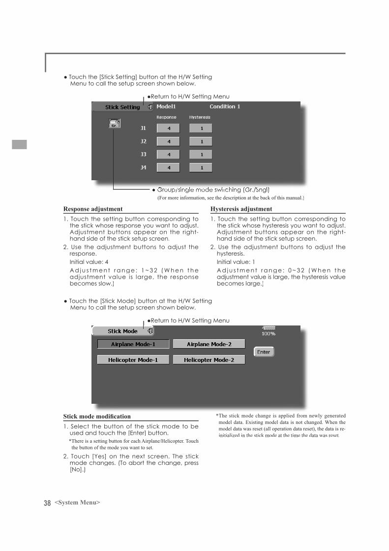
Stick SettingThis function sets the servo response and
hysteresis for stick operation for each condition.The control feeling of the stick can be adjusted tomatch the aerobatics.
Stick modeThe stick mode of the FX40 is set to mode 1 or 2
(factory setting). It can be changed to mode 2 or 1.Note: It may be necessary to change the stick
mode before setting the model data. The mode of an already set model and the mode of the currently used model are not changed. The model mode is applied to models added after the model mode change, or to models whose operation data has all been reset by data reset function.
Note: Set the throttle stick ratchet mechanism by referring to [Stick adjustment].
38 <System Menu>
Response adjustment
(For more information, see the description at the back of this manual.)
Hysteresis adjustment
*There is a setting button for each Airplane/Helicopter. Touch the button of the mode you want to set.
*The stick mode change is applied from newly generated model data. Existing model data is not changed. When the model data was reset (all operation data reset), the data is re-initialized in the stick mode at the time the data was reset.

39<System Menu>
InformationThe FX-40 system program version information,
CF card information (memory size, vacant capacity,
and product ID are displayed on the Informationscreen.
*When the CF card is not inserted, the CF card information isnot displayed.

40 <Model Basic Setting Procedure>
MODEL BASIC SETTING PROCEDURE
1. Model addition and callInitial setting assigns 1 model to the FX-40
transmitter. The Model Select function of theLinkage Menu is used to add models and to call models which are already set.
This is convenient when calling a model after its name has been registered. (The data of up to 30 models can be saved to the transmitter. More can also be saved to the accessory CF card.)
The currently called model name is displayed at the top of the screen. Before flying and before changing
When a new model was added, the Model typeselect screen and Frequency/Modulation mode/Receiver ID setup screen automatically appear. Please be aware that the transmitter will stop transmittingwhen you change the model.
2. Model type selectionSelect the model type matched to the wing type with
the Model Type select function of the Linkage Menu.For an airplane, select the model type from among the 3 types: airplane, glider, and motor glider. When theWing type select screen is displayed and the wing type is selected when selecting the model type, the Tail typeselect screen is displayed. Select the tail type matched to the fuselage.
There are 13 wing types and 3 tail types for airplane, glider, and motor glider.
Airplane/glider basic setting procedure
3. Fuselage linkageLink the ailerons, elevators, throttle, rudder, etc.
in accordance with the model's instruction manual. For a description of the connection method, see the Receiver and Servos Connection.
Note: The channel assignment of the FX-40 is different from that of our existing systems. Notethat even for the same "airplane model", when thewing type and tail type are different, the channel assignment may be different. (The channel assignedto each function can be checked at the Function menu of the Linkage Menu.)

41<Model Basic Setting Procedure>
4. Throttle cut settingThrottle cut can be performed with one touch by a
switch without changing the throttle trim position.Set throttle cut with the Throttle Cut function of
the Linkage Menu. After activating the throttle cut function and selecting the switch, adjust the throttle position so that the carburetor becomes full open. For safety, the throttle cut function operates the throttle stick in the 1/3 or less (slow side) position.
5. Idle down settingThe idling speed can be lowered with one touch by
a switch without changing the throttle trim position.Perform this setting with the Idle Down function of the Linkage Menu. After activating the Idle Down function and selecting the switch, adjust the idle down speed.For safety, the idle down function acts only when the throttle stick is in the 1/3 or less (slow side) position.
*While the Throttle Cut function is in operation, the IdleDown function does not work.
6. AFR (D/R)AFR function is used to adjust the throw and
operation curve of the stick, lever, and switch functions
This is normally used after End Point (ATV) hasdefined the maximum throw directions (End Point acts on ALL flight condition settings). When mixing is applied from one channel to another channel, both channels can be adjusted at the same time by adjusting the operation rate through the AFR function.
7. AirbrakeThis function is used when an air brake is necessary
when taking off or diving, etc.
The preset elevators and flaps (camber flap, brake
servos can be adjusted as needed. Also the speed of the
side/OUT side) A delay can be set for each condition, and a Cut switch which will turn OFF the delay can
a VR You can also set the Auto Mode, which will link Airbrake to a stick, switch, or dial. A separate stick
per model. You can assign all switches including sticks,
selection switches. You can also add delayed mixing to these functions in order to avoid sudden changes.
when you set more than one condition. In addition, you can copy conditions and/or change names of conditions.
The Condition Select function automatically allocates the Condition 1 for each model type. Condition 1 is the default
when a new model type is defined. This condition is always on, and remains on until other conditions are activated by switches.
The Condition Delay can be programmed for each channel. The Condition Delay is used to change the servo throw smoothly when switching conditions.
*When a new condition is added, "Condition1" data is automatically copied.
*Select the condition switch and set the new condition data in the
advance, the same data will be input at all the conditions. Select the single mode (Sngl) and adjust the condition you want to change.
9. When tailless wing model selected
mixing. This function cannot be performed at initial setting.

42 <Model Basic Setting Procedure>
1. Model addition and callDefault setting assigns 1 model to the FX-40. To
add new models or to call a model already set, use the Model Select function of the Linkage Menu.
This is convenient when calling a model after registering the model names in advance. (The data of up to 30 models can be saved at the transmitter. Data can also be saved to the accessory Data-Pack.)
The currently called model is displayed at the top
Please be aware that the transmitter will stoptransmitting when you change the model.
When a new model is added, the Model Type Select screen and Frequency/Modulation mode/Receiver IDsetup screen automatically appear. Change, or check that they match the type, frequency, and receiver typeof the model used.
2. Model type and swash type selectionWhen a separate model type is already selected,
select helicopter with the Model Type function of the Linkage Menu, and then select the swash type matched to the helicopter.
Helicopter basic setting procedure
3. Flight condition additionThe transmitter can install up to eight flight
conditions per model. You can assign all switches including sticks, switches, trim levers and trim switchesas flight-condition selection switches. You can also add delayed mixing to these functions in order to avoid sudden changes. Moreover, you can set priority
condition. In addition, you can copy conditions and/or change names of conditions. This command may alsobe used to define what switches and/or controls are
The Condition Select function automatically
the default condition, and is the only one active when a
and remains on until other conditions are activated by switches.
The Condition Delay can be programmed for each channel. The Condition Delay is used to change the servo throw smoothly when switching conditions.
The priority is throttle hold/idle up 2/idle up 1/normal. Throttle hold has the highest priority.
Add other conditions, as required.

43<Model Basic Setting Procedure>
5. Throttle curve settingThis function adjusts the pitch operation curve
in relation to the movement of the throttle stick for each condition.
(17 points curve)The pitch curve can be freely selected from linear
operation curve to smooth curve, and adjusted to match the curve you want by means of the T14MZ’spowerful Curve Edit Function (6 types of curves can be selected). Up to 17 points can be set for linear or curve types. However, when using the 3 points
smooth curve can be created by selecting the curvetype and reducing the number of input points to 3or 5, and then entering the specified value at the corresponding points that you created.
Call the throttle curve of each condition with thecondition select switch.
4. Fuselage linkageConnect the throttle rudder, ailerons, elevators,
pitch, and other rudder linkages in accordance withthe kit instruction manual. For a description of the connection method, see "Receiver and Servos Connection".
*The channel assignment of the FX-40 is different
assigned to each function can be checked at the Function menu of the Linkage Menu.)

44 <Model Basic Setting Procedure>
Example of pitch curve setting:
*Pitch curve graph display can be switched to pitch angledirect reading display.
º~6º
*Stability at hovering may be connected to the throttle curve. Adjustment is easy by using the hovering throttle function and hovering pitch function together.
º º
º
º º
6. Throttle hold settingCall the Throttle Hold function from the Model
Menu and switch to the throttle hold condition with the condition select switch.
Use this function when you want to suppressthe torque generated by the changes in the pitch and speed of the main rotor during pitch operation. Adjust it so that the nose does not swing in therudder direction. However, when using a headinghold gyro like those shown below, do not use Pitch to RUD mixing.
Call the Pitch to RUD mixing function from the Model Menu, and set the curve for each condition.
(17 points curve)Curve setting of up to 17 points is possible.
However, in the following setting example, asimple curve can be adjusted by using the [Linear] curve type.
Call the mixing curve of each condition with the condition select switch.
45<Model Basic Setting Procedure>
*For this curve, use the initial setting [Linear] curve type and adjust the left and right rates in the [Separate] mode.
º
*For this curve, [Linear] curve type can be used and the entirecurve can be lowered with the [Offset] button.
º*For this curve, [Linear] curve type can be used and the entire
curve can be lowered with the [Offset] button.
pitch interactionThe swash mix function is used to correct the
swash plate in the aileron (roll) direction and elevator (cyclic pitch) corresponding to eachoperation of each condition.
RPM loss caused by swash operation at aileronor elevator operation can be corrected with theThrottle Mix function of the Model Menu. Howclockwise and counterclockwise torque is applied when pirouetting can also be corrected.
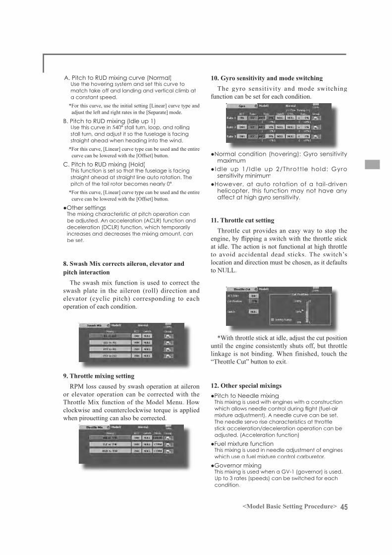
10. Gyro sensitivity and mode switchingThe gyro sensitivity and mode switching
function can be set for each condition.
11. Throttle cut settingThrottle cut provides an easy way to stop the
at idle. The action is not functional at high throttleto avoid accidental dead sticks. The switch’s location and direction must be chosen, as it defaults
*With throttle stick at idle, adjust the cut position until the engine consistently shuts off, but throttlelinkage is not binding. When finished, touch the “Throttle Cut” button to exit.
46 <Model Basic Setting Procedure>
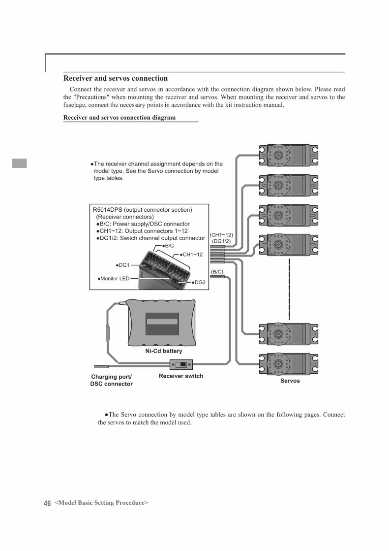
Receiver switch
Ni-Cd battery
Charging port/ DSC connector
~
~
Servos
Receiver and servos connection diagram
Receiver and servos connectionConnect the receiver and servos in accordance with the connection diagram shown below. Please read
the "Precautions" when mounting the receiver and servos. When mounting the receiver and servos to the fuselage, connect the necessary points in accordance with the kit instruction manual.
the servos to match the model used.

47<Model Basic Setting Procedure>
Servo connection by model typeThe FX-40 transmitter channels are automatically assigned for optimal combination according to the
type selected with the Model Type function of the Linkage Menu. The channel assignment (initial setting) for each model type is shown below. Connect the receiver and servos to match the type used.
*The set channels can be checked at the Function screen of the Linkage Menu. The channel assignments can also be changed. For more information, read the description of the Function menu.
Airplane/glider/motor glider
RX CH1AIL 2AIL 2AIL+1FLAP 2AIL+2FLAP
AirplaneGlider
AirplaneGlider
AirplaneGlider
AirplaneGlider
EP EP EP EP1 Elevator Elevator Elevator Elevator Elevator Elevator Elevator Elevator Elevator Elevator Elevator Elevator2 Rudder Rudder Rudder Rudder Rudder Rudder Rudder Rudder Rudder Rudder Rudder Rudder3 Throttle Motor AUX1 Throttle Motor AUX1 Throttle Motor AUX7 Throttle Motor AUX64 Aileron Aileron Aileron Aileron Aileron Aileron Aileron Aileron Aileron Aileron Aileron Aileron5 Gear AUX7 AUX7 Aileron2 Aileron2 Aileron2 Aileron2 Aileron2 Aileron2 Aileron2 Aileron2 Aileron26 Airbrake Airbrake Airbrake Gear AUX7 AUX7 Flap Flap Flap Gear AUX5 AUX57 AUX6 AUX6 AUX6 AUX6 AUX6 AUX6 Gear AUX6 AUX6 Flap Flap Flap8 AUX5 AUX5 AUX5 AUX5 AUX5 AUX5 AUX5 AUX5 AUX5 Flap2 Flap2 Flap29 AUX4 AUX4 AUX4 AUX4 AUX4 AUX4 AUX4 AUX4 AUX4 AUX4 AUX4 AUX410 AUX3 AUX3 AUX3 AUX3 AUX3 AUX3 AUX3 AUX3 AUX3 AUX3 AUX3 AUX311 AUX2 AUX2 AUX2 AUX2 AUX2 AUX2 AUX2 AUX2 AUX2 AUX2 AUX2 AUX212 AUX1 AUX1 AUX1 AUX1 AUX1 AUX1 AUX1 AUX1 AUX1 AUX1 AUX1 AUX1
VC1 AUX1 AUX1 AUX1 Camber Camber Camber Camber Camber Camber Camber Camber CamberVC2 AUX1 AUX1 AUX1 AUX1 AUX1 AUX1VC3 AUX1 AUX1 AUX1 AUX1 AUX1 AUX1 AUX1 AUX1 AUX1 AUX1 AUX1 AUX1VC4 AUX1 AUX1 AUX1 AUX1 AUX1 AUX1 AUX1 AUX1 AUX1 AUX1 AUX1 AUX1
RX CH2AIL+4FLAP 4AIL+2FLAP 4AIL+4FLAP
AirplaneGlider
AirplaneGlider
AirplaneGlider
EP EP EP1 Elevator Elevator Elevator Elevator Elevator Elevator Elevator Elevator Elevator2 Rudder Rudder Rudder Rudder Rudder Rudder Rudder Rudder Rudder3 Throttle Motor AUX4 Throttle Motor AUX4 Throttle Motor AUX24 Aileron Aileron Aileron Aileron Aileron Aileron Aileron Aileron Aileron5 Aileron2 Aileron2 Aileron2 Aileron2 Aileron2 Aileron2 Aileron2 Aileron2 Aileron26 Gear AUX3 AUX3 Gear AUX3 AUX3 Gear AUX1 AUX17 Flap Flap Flap Aileron3 Aileron3 Aileron3 Aileron3 Aileron3 Aileron38 Flap2 Flap2 Flap2 Aileron4 Aileron4 Aileron4 Aileron4 Aileron4 Aileron49 Flap3 Flap3 Flap3 Flap1 Flap1 Flap1 Flap1 Flap1 Flap110 Flap4 Flap4 Flap4 Flap2 Flap2 Flap2 Flap2 Flap2 Flap211 AUX2 AUX2 AUX2 AUX2 AUX2 AUX2 Flap3 Flap3 Flap312 AUX1 AUX1 AUX1 AUX1 AUX1 AUX1 Flap4 Flap4 Flap4
VC1 Camber Camber Camber Camber Camber Camber Camber Camber CamberVC2 AUX1 AUX1 AUX1VC3 AUX1 AUX1 AUX1 AUX1 AUX1 AUX1 AUX1 AUX1 AUX1VC4 AUX1 AUX1 AUX1 AUX1 AUX1 AUX1 AUX1 AUX1 AUX1
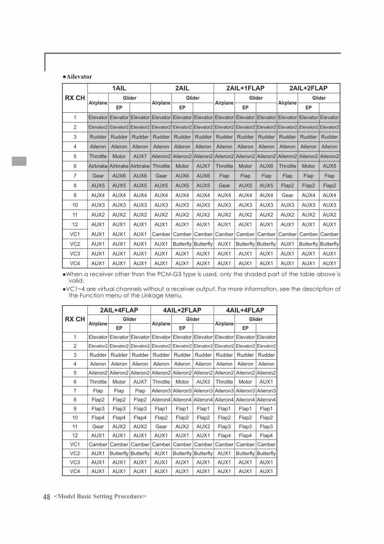
48 <Model Basic Setting Procedure>
RX CH1AIL 2AIL 2AIL+1FLAP 2AIL+2FLAP
AirplaneGlider
AirplaneGlider
AirplaneGlider
AirplaneGlider
EP EP EP EP
1 Elevator Elevator Elevator Elevator Elevator Elevator Elevator Elevator Elevator Elevator Elevator Elevator
2 Elevator2 Elevator2 Elevator2 Elevator2 Elevator2 Elevator2 Elevator2 Elevator2 Elevator2 Elevator2 Elevator2 Elevator2
3 Rudder Rudder Rudder Rudder Rudder Rudder Rudder Rudder Rudder Rudder Rudder Rudder
4 Aileron Aileron Aileron Aileron Aileron Aileron Aileron Aileron Aileron Aileron Aileron Aileron
5 Throttle Motor AUX7 Aileron2 Aileron2 Aileron2 Aileron2 Aileron2 Aileron2 Aileron2 Aileron2 Aileron2
6 Airbrake Airbrake Airbrake Throttle Motor AUX7 Throttle Motor AUX6 Throttle Motor AUX5
7 Gear AUX6 AUX6 Gear AUX6 AUX6 Flap Flap Flap Flap Flap Flap
8 AUX5 AUX5 AUX5 AUX5 AUX5 AUX5 Gear AUX5 AUX5 Flap2 Flap2 Flap2
9 AUX4 AUX4 AUX4 AUX4 AUX4 AUX4 AUX4 AUX4 AUX4 Gear AUX4 AUX4
10 AUX3 AUX3 AUX3 AUX3 AUX3 AUX3 AUX3 AUX3 AUX3 AUX3 AUX3 AUX3
11 AUX2 AUX2 AUX2 AUX2 AUX2 AUX2 AUX2 AUX2 AUX2 AUX2 AUX2 AUX2
12 AUX1 AUX1 AUX1 AUX1 AUX1 AUX1 AUX1 AUX1 AUX1 AUX1 AUX1 AUX1
VC1 AUX1 AUX1 AUX1 Camber Camber Camber Camber Camber Camber Camber Camber Camber
VC2 AUX1 AUX1 AUX1 AUX1 AUX1 AUX1
VC3 AUX1 AUX1 AUX1 AUX1 AUX1 AUX1 AUX1 AUX1 AUX1 AUX1 AUX1 AUX1
VC4 AUX1 AUX1 AUX1 AUX1 AUX1 AUX1 AUX1 AUX1 AUX1 AUX1 AUX1 AUX1
RX CH2AIL+4FLAP 4AIL+2FLAP 4AIL+4FLAP
AirplaneGlider
AirplaneGlider
AirplaneGlider
EP EP EP1 Elevator Elevator Elevator Elevator Elevator Elevator Elevator Elevator Elevator
2 Elevator2 Elevator2 Elevator2 Elevator2 Elevator2 Elevator2 Elevator2 Elevator2 Elevator2
3 Rudder Rudder Rudder Rudder Rudder Rudder Rudder Rudder Rudder
4 Aileron Aileron Aileron Aileron Aileron Aileron Aileron Aileron Aileron
5 Aileron2 Aileron2 Aileron2 Aileron2 Aileron2 Aileron2 Aileron2 Aileron2 Aileron2
6 Throttle Motor AUX7 Throttle Motor AUX3 Throttle Motor AUX1
7 Flap Flap Flap Aileron3 Aileron3 Aileron3 Aileron3 Aileron3 Aileron3
8 Flap2 Flap2 Flap2 Aileron4 Aileron4 Aileron4 Aileron4 Aileron4 Aileron4
9 Flap3 Flap3 Flap3 Flap1 Flap1 Flap1 Flap1 Flap1 Flap1
10 Flap4 Flap4 Flap4 Flap2 Flap2 Flap2 Flap2 Flap2 Flap2
11 Gear AUX2 AUX2 Gear AUX2 AUX2 Flap3 Flap3 Flap3
12 AUX1 AUX1 AUX1 AUX1 AUX1 AUX1 Flap4 Flap4 Flap4
VC1 Camber Camber Camber Camber Camber Camber Camber Camber Camber
VC2 AUX1 AUX1 AUX1
VC3 AUX1 AUX1 AUX1 AUX1 AUX1 AUX1 AUX1 AUX1 AUX1
VC4 AUX1 AUX1 AUX1 AUX1 AUX1 AUX1 AUX1 AUX1 AUX1

49<Model Basic Setting Procedure>
RX CH2AIL 2AIL+1FLAP 2AIL+2FLAP
AirplaneGlider
AirplaneGlider
AirplaneGlider
EP EP EP1 Rudder Rudder Rudder Rudder Rudder Rudder Rudder Rudder Rudder2 Rudder2 Rudder2 Rudder2 Rudder2 Rudder2 Rudder2 Rudder2 Rudder2 Rudder23 Throttle Motor AUX1 Throttle Motor AUX7 Throttle Motor AUX64 Aileron Aileron Aileron Aileron Aileron Aileron Aileron Aileron Aileron5 Aileron2 Aileron2 Aileron2 Aileron2 Aileron2 Aileron2 Aileron2 Aileron2 Aileron26 Gear AUX7 AUX7 Flap Flap Flap Gear AUX5 AUX57 AUX6 AUX6 AUX6 Gear AUX6 AUX6 Flap Flap Flap8 AUX5 AUX5 AUX5 AUX5 AUX5 AUX5 Flap2 Flap2 Flap29 AUX4 AUX4 AUX4 AUX4 AUX4 AUX4 AUX4 AUX4 AUX4
10 AUX3 AUX3 AUX3 AUX3 AUX3 AUX3 AUX3 AUX3 AUX311 AUX2 AUX2 AUX2 AUX2 AUX2 AUX2 AUX2 AUX2 AUX212 AUX1 AUX1 AUX1 AUX1 AUX1 AUX1 AUX1 AUX1 AUX1
VC1 Elevator Elevator Elevator Elevator Elevator Elevator Elevator Elevator ElevatorVC2 AUX1 AUX1 AUX1 Camber Camber Camber Camber Camber CamberVC3 AUX1 AUX1 AUX1 AUX1 AUX1VC4 AUX1 AUX1 AUX1 AUX1 AUX1 AUX1 AUX1 AUX1 AUX1
RX CH2AIL+4FLAP 4AIL+2FLAP 4AIL+4FLAP
AirplaneGlider
AirplaneGlider
AirplaneGlider
EP EP EP1 Rudder Rudder Rudder Rudder Rudder Rudder Rudder Rudder Rudder2 Rudder2 Rudder2 Rudder2 Rudder2 Rudder2 Rudder2 Rudder2 Rudder2 Rudder23 Throttle Motor AUX4 Throttle Motor AUX4 Throttle Motor AUX24 Aileron Aileron Aileron Aileron Aileron Aileron Aileron Aileron Aileron5 Aileron2 Aileron2 Aileron2 Aileron2 Aileron2 Aileron2 Aileron2 Aileron2 Aileron26 Gear AUX3 AUX3 Gear AUX3 AUX3 Gear AUX1 AUX17 Flap Flap Flap Aileron3 Aileron3 Aileron3 Aileron3 Aileron3 Aileron38 Flap2 Flap2 Flap2 Aileron4 Aileron4 Aileron4 Aileron4 Aileron4 Aileron49 Flap3 Flap3 Flap3 Flap1 Flap1 Flap1 Flap1 Flap1 Flap1
10 Flap4 Flap4 Flap4 Flap2 Flap2 Flap2 Flap2 Flap2 Flap211 AUX2 AUX2 AUX2 AUX2 AUX2 AUX2 Flap3 Flap3 Flap312 AUX1 AUX1 AUX1 AUX1 AUX1 AUX1 Flap4 Flap4 Flap4
VC1 Elevator Elevator Elevator Elevator Elevator Elevator Elevator Elevator ElevatorVC2 Camber Camber Camber Camber Camber Camber Camber Camber CamberVC3 AUX1 AUX1 AUX1VC4 AUX1 AUX1 AUX1 AUX1 AUX1 AUX1 AUX1 AUX1 AUX1

50 <Model Basic Setting Procedure>
CH H-4 Swash All Other1 Throttle Throttle
2 Rudder Rudder
3 Aileron Gyro
4 Elevator 1 Aileron
5 Pitch Elevator
6 Elevator 2 Pitch
7 Gyro Governor 1
8 Governor 1 Governor 2
9 Governor 2 Needle
10 Needle AUX3
11 AUX2 AUX2
12 AUX1 AUX1
VC1 AUX1 AUX1
VC2 AUX1 AUX1
VC3 AUX1 AUX1
VC4 AUX1 AUX1
Helicopter
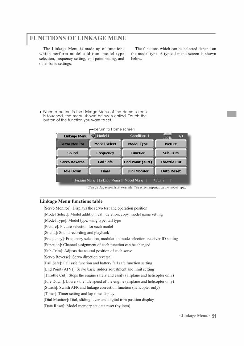
51<Linkage Menu>
FUNCTIONS OF LINKAGE MENUThe Linkage Menu is made up of functions
which perform model addition, model typeselection, frequency setting, end point setting, and other basic settings.
The functions which can be selected depend on the model type. A typical menu screen is shown below.
(The display screen is an example. The screen depends on the model type.)
Linkage Menu functions table[Servo Monitor]: Displays the servo test and operation position[Model Select]: Model addition, call, deletion, copy, model name setting[Model Type]: Model type, wing type, tail type[Picture]: Picture selection for each model[Sound]: Sound recording and playback[Frequency]: Frequency selection, modulation mode selection, receiver ID setting[Function]: Channel assignment of each function can be changed[Sub-Trim]: Adjusts the neutral position of each servo[Servo Reverse]: Servo direction reversal[Fail Safe]: Fail safe function and battery fail safe function setting[End Point (ATV)]: Servo basic rudder adjustment and limit setting[Throttle Cut]: Stops the engine safely and easily (airplane and helicopter only)[Idle Down]: Lowers the idle speed of the engine (airplane and helicopter only)[Swash]: Swash AFR and linkage correction function (helicopter only)[Timer]: Timer setting and lap time display[Dial Monitor]: Dial, sliding lever, and digital trim position display[Data Reset]: Model memory set data reset (by item)
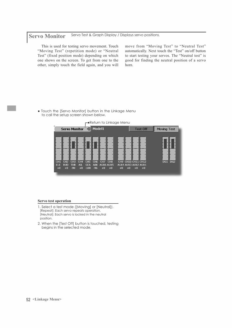
52 <Linkage Menu>
Servo MonitorThis is used for testing servo movement. Touch
“Moving Test” (repetition mode) or “Neutral Test” (fixed position mode) depending on whichone shows on the screen. To get from one to the other, simply touch the field again, and you will
move from “Moving Test” to “Neutral Test”automatically. Next touch the “Test” on/off button to start testing your servos. The “Neutral test” is good for finding the neutral position of a servo horn.
Servo test operation

53<Linkage Menu>
Model SelectThis function is used to load the settings of the
desired model into the FX-40’s memory.The settings may be selected from either the
transmitter’s built-in memory or a Data-Pack CFDP32M (Compact Flash card; 32MB). Remember that up to 30 model memories are available in the transmitter; these may be stored in the CFDP32M card.
The name of the model stored in the transmitter and the Data-Pack may be changed. This can be very useful to tell different models settings apart. Each model name
can be as long as 32 characters, and the model name always appears in the display screen.
The Copy function is used to copy one set of model data into a second memory within the transmitter and the Data-Pack. It may be used for getting a head-start on setting up models with almost the same settings (only
complete model from scratch). Also, this function may be used to make a backup copy of a model setup before any changes are made.
(The display screen is an example. The screen depends on the model type.)(Model list)
Model call
Model addition
*When a new model is added, the Model Type screen and Frequency screen are automatically displayed. Check or change the model and frequency. If there are no changes, touch the Model Type and Frequency icons.
*The added model is displayed in the model list.
Model deletion
Model name change
*Up to 32 characters can be input at the model name. Japanese language input is also possible.
(For a detailed description of the input method, see "User Name Registration/Character Input Method" of the BasicOperation section.
Model copy
*If there is no model of the same name at the copydestination, the name of the copy source is saved. If there is a model of the same name, a number is appended to theend of the model name and the model is copied. Change thename later.

54 <Linkage Menu>
Model Type
(The display screen is an example. The screen depends on the model type.)
Seven types of main wings and three types of tail wings are available for airplanes. Seven swash types are available for helicopters. Seventypes of main wings and three types of tail wingsare available for gliders. Functions and mixing functions necessary for each model type are set in advance at the factory.
Model type selection
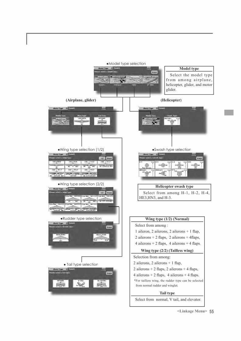
55<Linkage Menu>
Model typeSelect the model type
f r o m a m o n g a i r p l a n e ,helicopter, glider, and motor glider.
(Airplane, glider) (Helicopter)
Wing type (1/2) (Normal)Select from among :
Wing type (2/2) (Tailless wing)Selection from among:
*For tailless wing, the rudder type can be selected from normal rudder and winglet.
Tail typeSelect from normal, V tail, and elevator.
Helicopter swash typeSelect from among H-1, H-2, H-4,
HE3,HN3, and H-3.
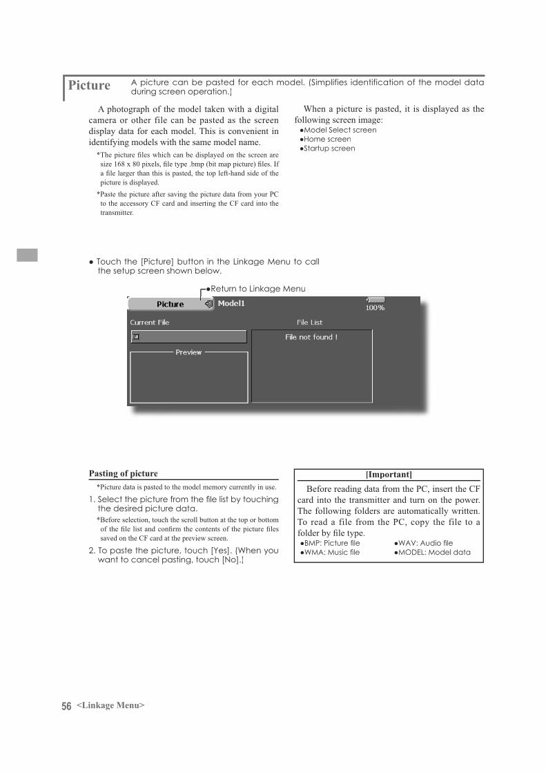
56 <Linkage Menu>
Picture A photograph of the model taken with a digital
camera or other file can be pasted as the screen display data for each model. This is convenient inidentifying models with the same model name.
picture is displayed.*Paste the picture after saving the picture data from your PC
to the accessory CF card and inserting the CF card into the transmitter.
When a picture is pasted, it is displayed as thefollowing screen image:
Pasting of picture*Picture data is pasted to the model memory currently in use.
*Before selection, touch the scroll button at the top or bottom
saved on the CF card at the preview screen.
[Important]Before reading data from the PC, insert the CF
card into the transmitter and turn on the power.The following folders are automatically written. To read a file from the PC, copy the file to a

57<Linkage Menu>
Sound
[Important]Before reading data from a PC, insert the CF
card into the transmitter and turn on the power.The following folders are automatically written. When reading a file from the PC, copy it to a
Sounds recorded with the microphone built into
CF card from the PC can be played back whenthe power switch is turned on and off or by preset switch.
*The recording time from the microphone is up to 3 seconds/
*When recording, insert the CF card into the transmitter.*The only audio file type which can be recorded is .wav.
Only the sounds recorded with the built-in microphone or an
back.
Setup screens No. 3 to 24 can be individuallyassigned to audio file switches, etc. The playback
operated. This can be used when playing back thename of maneuvers, etc.
Voice Recording
*You can only assign a sound data stored from your PC to a Data-Pack.
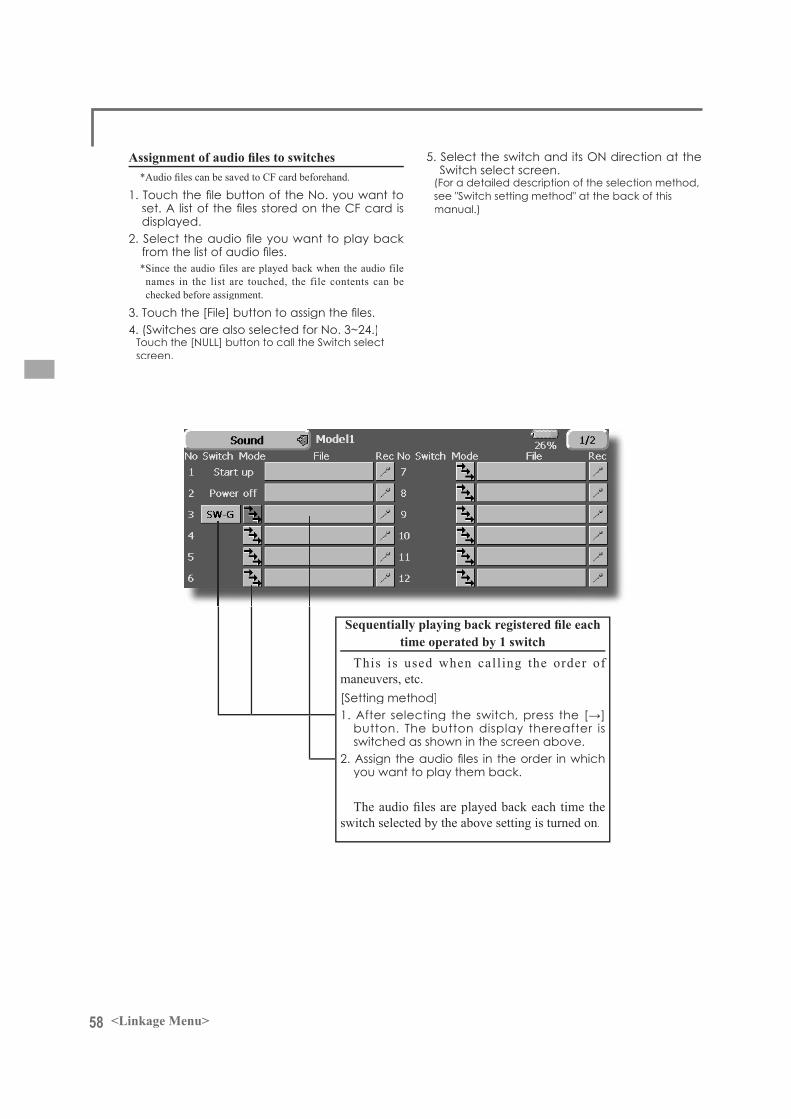
58 <Linkage Menu>
*Since the audio files are played back when the audio file names in the list are touched, the file contents can bechecked before assignment.
time operated by 1 switchThis is used when calling the order of
maneuvers, etc.
switch selected by the above setting is turned on.

59<Linkage Menu>
Frequency settingThe FX-40 transmitter uses a synthesizer system.
Its frequency can be changed within the range of the frequency band of the module used.
The frequency of the R5014DPS receiver is set from the transmitter. Use a receiver matched to thefrequency band of the transmitter.
Receiver ID codeWhen the R5014DPS receiver (PCM-G3
receiver) is used, the ID code located on the back of the receiver case must be entered.
*When two receivers are used with a large model, etc., enter the 2nd receiver ID also.
Frequency
Frequency switching methodFor a description of the frequency switching and
ID setting methods, refer to the procedure given inthe Basic Operation section.
Modulation mode change
*When switching from the PCM-G3 mode to another mode, the mode cannot be switched if the number of channels is
Modulation mode selectionWith the FX-40, 3 modulation modes (PCM-G3/
PCM1024/PPM (FM)) can be selected. Select themodulation mode matched to the type of receiver used.
Receiver ID code input
*Once the ID code is set, it does not have to be set again aslong as the receiver is not changed.
WARNING
waves only after verifying the frequency.*Also change the frequency clip. Emitting radio waves with-

60 <Linkage Menu>
FunctionWhen you select model and wing (swash) types,
you will find that the optimized combinations of servo output channels and functions have beenalready preset. If you would like, on the function-setting screen of the linkage menu, you can freelychange combinations of servo output channels,functions (aileron, elevator, etc), and input controllers (sticks, switches, trim levers and trim switches). You can also assign the same function to multiple servo output channels such as assigningelevator function to CH2 and CH3.
DG1, DG2 (switch channels)These two channels can be used as switch
channels. You can freely change combinationsbetween servo output channels and input controllers(sticks, switches, trim levers and trim switches).
VC1~VC4 (virtual channels)These four channels can be set as virtual functions
that do not have servo output channels. You can freely change combinations between functions(aileron, elevator, etc) and input controllers (sticks, switches, trim levers and trim switches).
(The display screen is an example. The screen depends on the model type.)
(VC1-4, DC-1-2)
Function change
*Multiple channels can be assigned to 1 function.
Servo Output ChannelsFor PCMG3 mode, you can set twelve linear
channels and two digital channels. For PCM1024 mode, you can set eight linear channels and onedigital channel. For PPM mode, you can set only eight linear channels.
Operation control change
*The same control can be assigned to multiple channels.

61<Linkage Menu>
(The display screen is an example. The screen depends on the model type.)
last page
Trim change

62 <Linkage Menu>
Sub-Trim
(The display screen is an example. The screen depends on the model type.)
The Sub-Trim function is used to set the servo neutral position, and may be used to make fineadjustments to the control surface after linkagesand pushrods are hooked up. When you begin to set up a model, be sure that the digital trims are set to their center position.
Sub trim adjustment
*See above
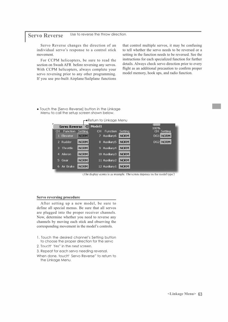
63<Linkage Menu>
Servo Reverse
(The display screen is an example. The screen depends on the model type.)
Servo Reverse changes the direction of anindividual servo’s response to a control stick movement.
For CCPM helicopters, be sure to read thesection on Swash AFR before reversing any servos. With CCPM helicopters, always complete your servo reversing prior to any other programming. If you use pre-built Airplane/Sailplane functions
Servo reversing procedureAfter setting up a new model, be sure to
define all special menus. Be sure that all servos are plugged into the proper receiver channels. Now, determine whether you need to reverse any channels by moving each stick and observing the corresponding movement in the model’s controls.
that control multiple servos, it may be confusing to tell whether the servo needs to be reversed or a setting in the function needs to be reversed. See theinstructions for each specialized function for further details. Always check servo direction prior to every
model memory, hook ups, and radio function.

64 <Linkage Menu>
Fail Safe
(The display screen is an example. The screen depends on the model type.)
The Failsafe function may be used to set up positions that the servos move to in the case of radio interference.
This function only works with G3 or PCM receivers(FM receivers do not have failsafe capability).
When the receiver battery voltage drops, the servocan be moved to a preset position. (Battery fail safe function) A battery fail safe function reset switch can be set. (Initial setting: Throttle stick maximum slow side)
You may set either of two positions for each channel: Hold, where the servo maintains its last commanded position, or Failsafe, where each servo moves to a predetermined position. You may choose either mode for each channel.
The FX-40 system also provides you with an advanced battery monitoring function that warns you when the receiver battery has only alittle power remaining. In this case, each servo is
Fail safe setting procedureDecide which channels you want to go to preset
positions, and which ones you want to maintain their last commanded position. To select the failsafe mode you wish to set, use the F/S button. Thisbutton toggles between the two modes. (Hold, F/S)F/S mode setting:
*When you want to return that channel to the Hold mode, touch the [F/S] button again.
Battery fail safe setting procedureTo select the B.F/S mode, touch the [B.F/S]
button. Each time the button is touched, it toggles
control on the transmitter (default is throttle), do not continue to fly, land as soon as possible.Remember, if the predefined control suddenly moves to a position you did not command, land at once and check your receiver battery.
when receiver battery voltage becomes low.
WARNINGFor safety, always set the fail safe functions.
the servo moves to the maximum slow side for airplanes and to the slow side from the hovering position for helicopters.Crashing of the model at full high when normal radio wavescannot be received due to interference, etc., is very dangerous.
engine malfunction and will be reset at throttle slow and the model
between [OFF] and [B.F/S].B.F/S setting:
*When you want to return that channel to OFF, touch the [B.F/S] button again.
Battery Failsafe Release FunctionThis function releases the predefined control
from it's held position after indicating that your receiver battery is low.
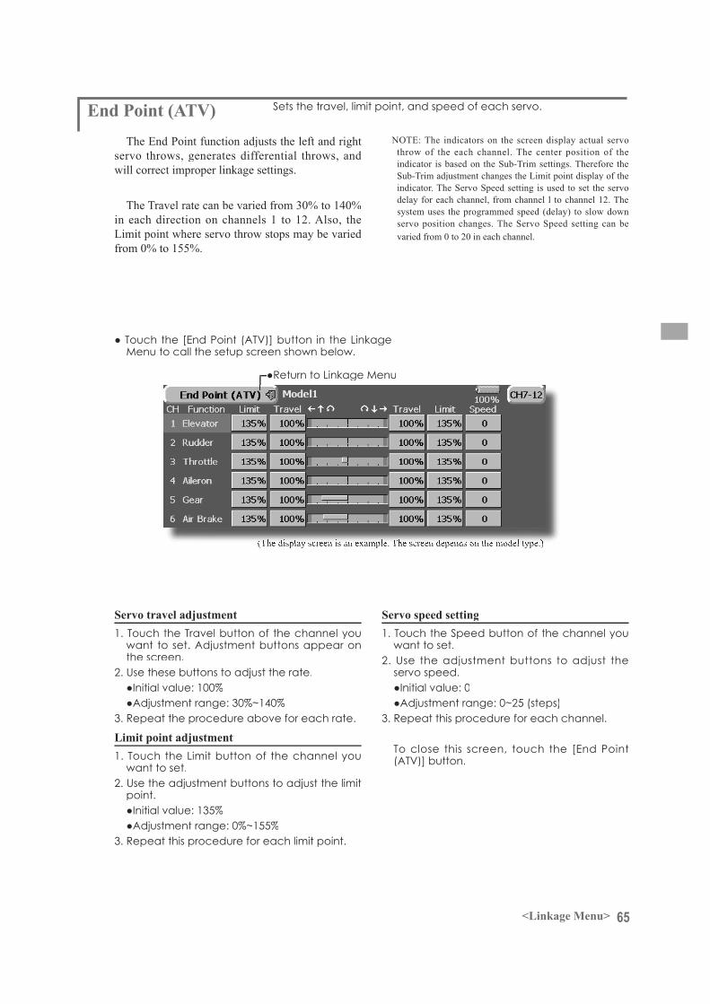
65<Linkage Menu>
End Point (ATV)
(The display screen is an example. The screen depends on the model type.)
The End Point function adjusts the left and right servo throws, generates differential throws, and will correct improper linkage settings.
The Travel rate can be varied from 30% to 140%in each direction on channels 1 to 12. Also, theLimit point where servo throw stops may be varied from 0% to 155%.
Servo travel adjustment
Limit point adjustment
NOTE: The indicators on the screen display actual servo throw of the each channel. The center position of theindicator is based on the Sub-Trim settings. Therefore the Sub-Trim adjustment changes the Limit point display of the indicator. The Servo Speed setting is used to set the servo delay for each channel, from channel l to channel 12. Thesystem uses the programmed speed (delay) to slow down servo position changes. The Servo Speed setting can be varied from 0 to 20 in each channel.
Servo speed setting
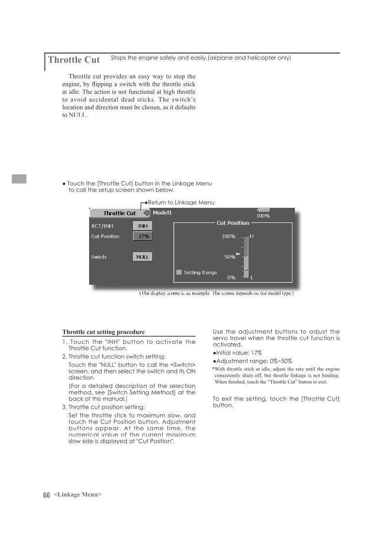
66 <Linkage Menu>
Throttle Cut
(The display screen is an example. The screen depends on the model type.)
Throttle cut provides an easy way to stop the
at idle. The action is not functional at high throttle to avoid accidental dead sticks. The switch’slocation and direction must be chosen, as it defaults to NULL.
Throttle cut setting procedure
*With throttle stick at idle, adjust the rate until the engine consistently shuts off, but throttle linkage is not binding.
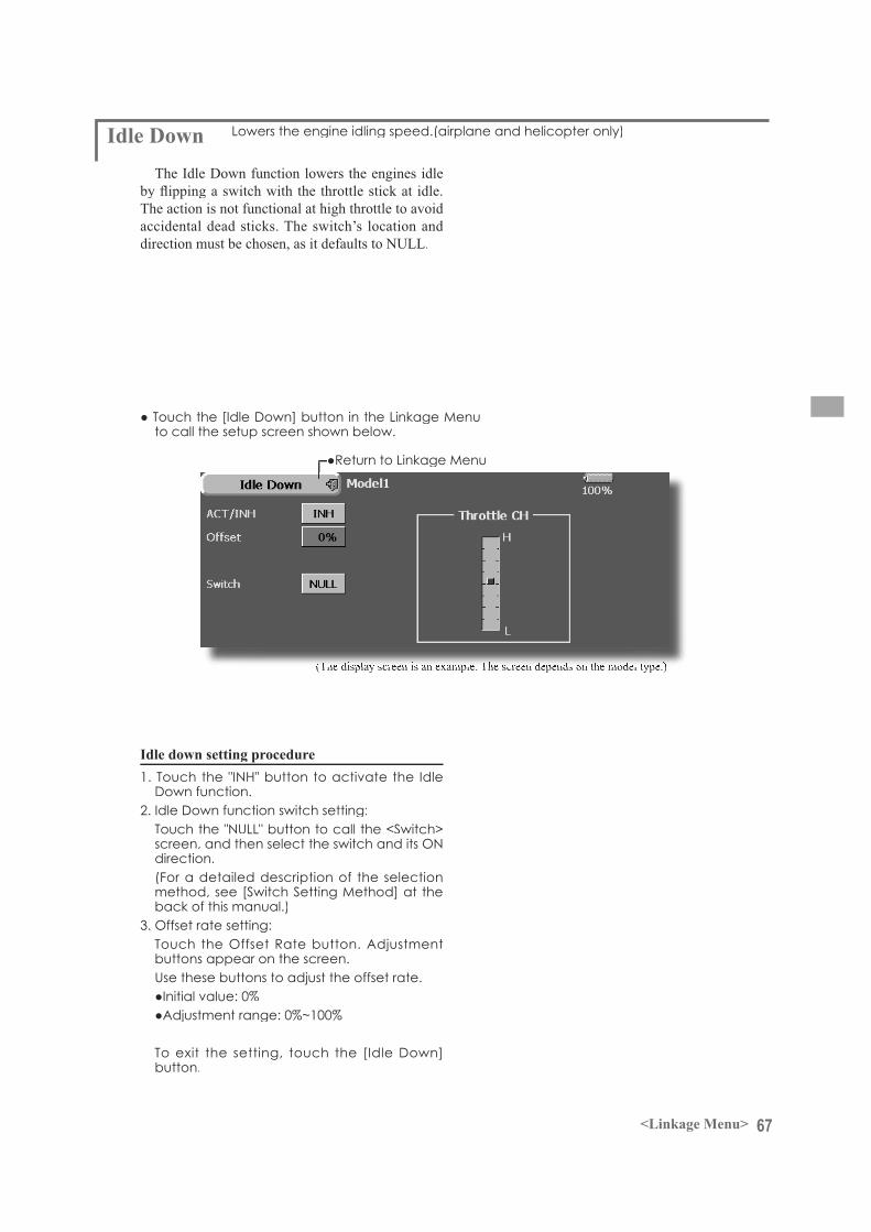
67<Linkage Menu>
Idle Down
(The display screen is an example. The screen depends on the model type.)
The Idle Down function lowers the engines idle
The action is not functional at high throttle to avoid accidental dead sticks. The switch’s location and direction must be chosen, as it defaults to NULL.
Idle down setting procedure
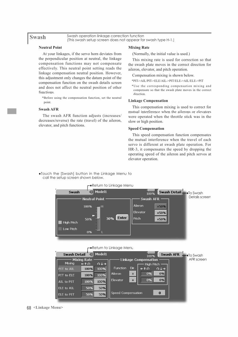
68 <Linkage Menu>
SwashNeutral Point
At your linkages, if the servo horn deviates from the perpendicular position at neutral, the linkagecompensation functions may not compensateeffectively. This neutral point setting reads the linkage compensation neutral position. However, this adjustment only changes the datum point of the compensation function on the swash details screen and does not affect the neutral position of other functions.
*Before using the compensation function, set the neutralpoint.
Swash AFRThe swash AFR function adjusts (increases/
decreases/reverse) the rate (travel) of the aileron, elevator, and pitch functions.
Mixing Rate(Normally, the initial value is used.)This mixing rate is used for correction so that
the swash plate moves in the correct direction for aileron, elevator, and pitch operation.
Compensation mixing is shown below.*PIT->AIL/PIT->ELE/AIL->PIT/ELE->AIL/ELE->PIT*Use the corresponding compensat ion mixing and
compensate so that the swash plate moves in the correct direction.
Linkage CompensationThis compensation mixing is used to correct for
mutual interference when the ailerons or elevators were operated when the throttle stick was in the slow or high position.
Speed CompensationThis speed compensation function compensates
the mutual interference when the travel of eachservo is different at swash plate operation. For HR-3, it compensates the speed by dropping the operating speed of the aileron and pitch servos at elevator operation.
69<Linkage Menu>
Neutral point setting procedure*Becomes the compensation datum point.*Adjusting the servo horn so that the neutral point position is
near the 50% position makes the mixing amount small.
*The neutral point is displayed on the screen.
Swash AFR setting procedure
Mixing rate setting procedure
Linkage correction setting procedure
Speed compensation setting procedure
Notes:

70 <Linkage Menu>
TimerThe Timer function may be set for any desired time,
etc. Two independent timers are provided for your use. The timers are stored independently with each model, meaning that when you switch between model setups,the timer associated with the new model is brought upautomatically.
The timers may be set to start and stop from the motion of any switch or stick. You may set the ON and OFF directions freely. Each timer has a capacity of upto 59 minutes 59 seconds.
Up timer/down timer selection
*Each time this button is touched, it toggles between UP and DOWN.
Start/stop switch setting
Each timer may be set for count-down or count up operation with a target time. Also Split Timemay be counted.
If a target time is set and the timer reaches the set time, a buzzer sound for each count is generated.
Countdown timers sound one short beep during the last twenty seconds and two short beeps during the last ten seconds before reaching the target, then a long tone at the target time, and continue counting with displaying a minus (-) sign. Count-up timers also beep the last twenty and ten seconds, beep the target time, and keep counting upwards until shut down.
Lap time switch selection
Timer operation
<Lap time list>

71<Linkage Menu>
Dial MonitorDigital Trim Position display (T1-T8, CD)
The Dial Monitor displays the current position and the operation step amount of each Digital Trim. The trim step can be set directly on the dial monitor menu.
VR and slide lever position display (LD, RD,L1-L3)
Displays the current position (black ) and last operating position (green ) of the VRs and slider levers.
Knob and Lever Position display(LD, RD, LS, L1-L3)
The Dial Monitor displays the current position and last operation position of each knob and lever.Although neither knob nor lever can hold the last operation position because of they are “analog” type, the position data during the last operation ismemorized in the model memory. By moving the knob and lever to the position displayed on this monitor, the last operation position is recalled.
Recalling Dial Position(LD, RD, LS, L1-L3)
The dial position data at the last operation isdisplayed for each knob and lever in this monitor.(Green arrow)
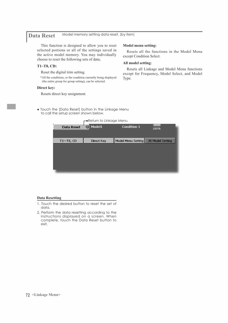
72 <Linkage Menu>
Data ResetThis function is designed to allow you to reset
selected portions or all of the settings saved inthe active model memory. You may individuallychoose to reset the following sets of data;
T1~T8, CD:Reset the digital trim setting.*All the conditions, or the condition currently being displayed
(the entire group for group setting), can be selected.
Direct key:Resets direct key assignment.
Data Resetting
Model menu setting:Resets all the functions in the Model Menu
except Condition Select.
All model setting:Resets all Linkage and Model Menu functions
except for Frequency, Model Select, and Model Type.
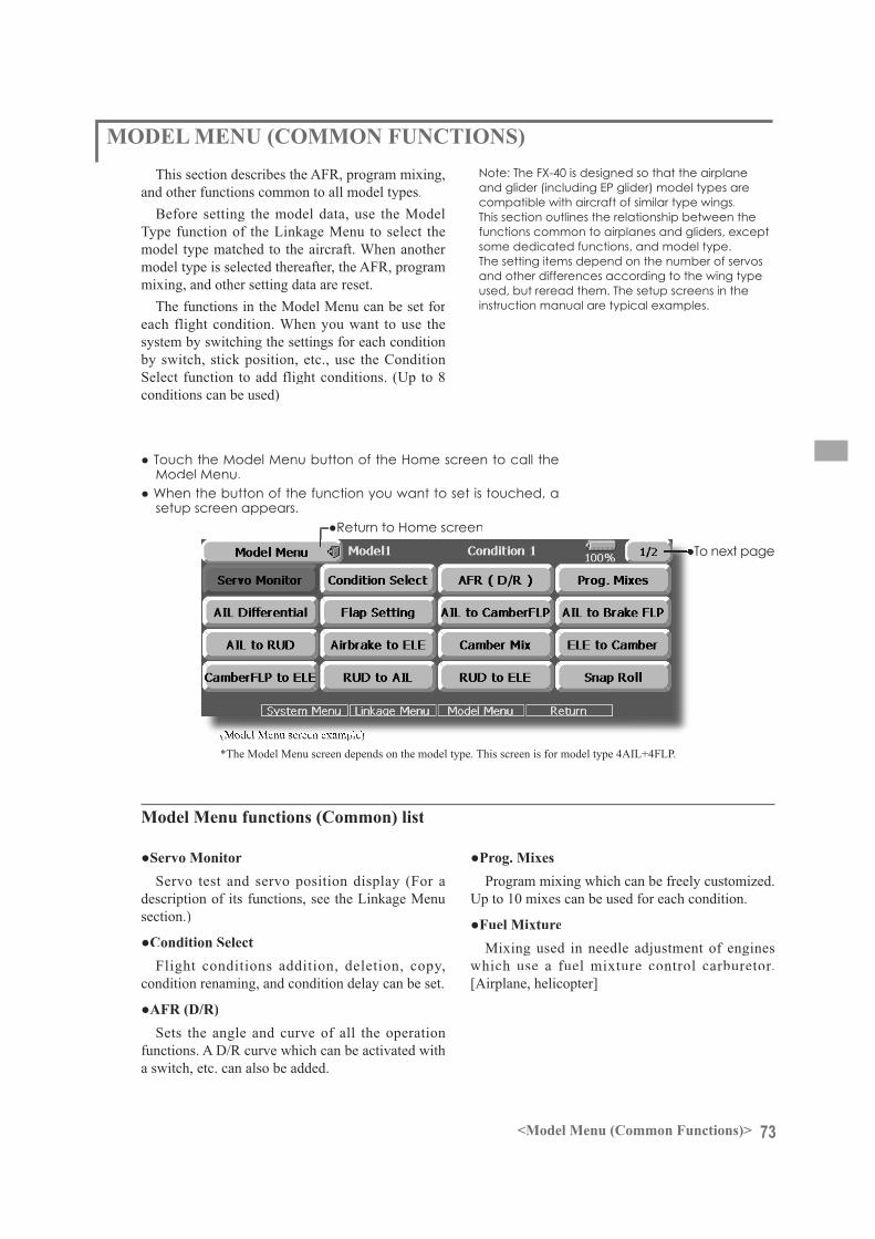
73<Model Menu (Common Functions)>
MODEL MENU (COMMON FUNCTIONS)This section describes the AFR, program mixing,
and other functions common to all model types.Before setting the model data, use the Model
Type function of the Linkage Menu to select the model type matched to the aircraft. When another model type is selected thereafter, the AFR, programmixing, and other setting data are reset.
The functions in the Model Menu can be set for each flight condition. When you want to use the system by switching the settings for each condition by switch, stick position, etc., use the ConditionSelect function to add flight conditions. (Up to 8conditions can be used)
Note: The FX-40 is designed so that the airplaneand glider (including EP glider) model types arecompatible with aircraft of similar type wings.This section outlines the relationship between the functions common to airplanes and gliders, exceptsome dedicated functions, and model type.The setting items depend on the number of servosand other differences according to the wing typeused, but reread them. The setup screens in the instruction manual are typical examples.
setup screen appears.
(Model Menu screen example)*The Model Menu screen depends on the model type. This screen is for model type 4AIL+4FLP.
Model Menu functions (Common) list
Servo test and servo position display (For adescription of its functions, see the Linkage Menusection.)
Flight conditions addition, deletion, copy, condition renaming, and condition delay can be set.
Sets the angle and curve of all the operation functions. A D/R curve which can be activated witha switch, etc. can also be added.
Program mixing which can be freely customized. Up to 10 mixes can be used for each condition.
Mixing used in needle adjustment of engineswhich use a fuel mixture control carburetor. [Airplane, helicopter]

74 <Model Menu (Common Functions)>
Condition Select Flight conditions addition, deletion, copy, condition renaming, and condition
The functions in the Model Menu can be used by switching the settings of up to 8 flight conditions
conditions.When you do not want to use the Condition
Select function, this setting is unnecessary. In this case, use the flight conditions (Condition 1) assigned at initial setting.
addition to ordinary toggle switch, is possible as the flight condition selector switch, this
Unnecessary fuselage motion generated
when there are sudden changes in the servo positions and when there are variations in the operating time between channels during condition switching can be suppressed. The delay can be set for each channel.
sw i tch ing des t inat ion cond i t ion , the related function changes after a delay corresponding to the set amount.
operation priority can be freely changed.
selected condition name is displayed on
added, give it a name which can be easily
(Conditions List)
1. Touch the condition whose priority
List.
condition has the highest priority.)*The initial setting condition cannot be
moved. It has the lowest priority.
*Only the number of buttons corresponding to theconditions which can be added are displayed.
the buttons.*The selected conditions are added to Conditions
List.
switching.(For a description of the switch selection method,
see next page.)
conditions is copied.
b y t o u c h i n g t h econdition you want to
button.
i s t o u c h e d , t h e condition is reset. (To abort resetting, touch
touching the conditionyou want to rename in
3. Enter the new name from
appears on the screen. (For a description of the methodof using the Japanese language conver s ion
Operation section.)
name is registered. (To abort registration, touch the
copy source conditions.3. Next, select the condition by touching the copy
destination condition.
(Currently selected condition name)
setting(For a description of the setting method, see the next page.)
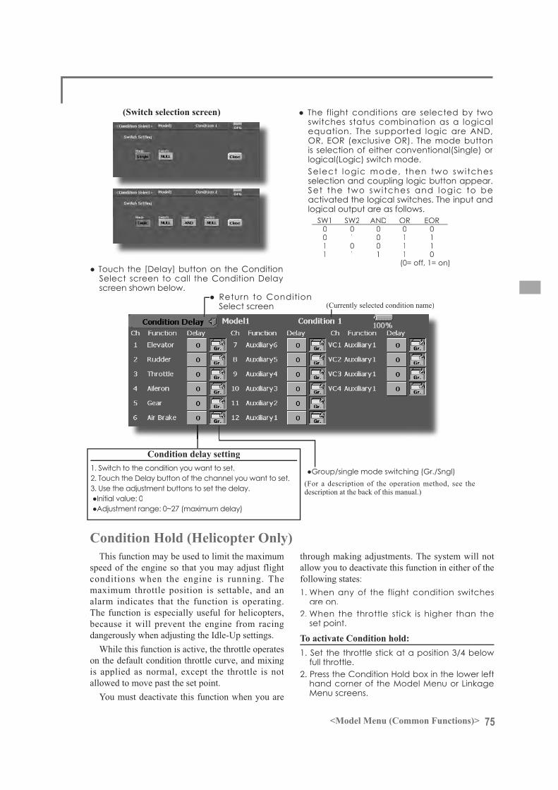
75<Model Menu (Common Functions)>
screen shown below.
(Currently selected condition name)
3. Use the adjustment buttons to set the delay. (For a description of the operation method, see thedescription at the back of this manual.)
This function may be used to limit the maximumspeed of the engine so that you may adjust flight conditions when the engine is running. Themaximum throttle position is settable, and analarm indicates that the function is operating.The function is especially useful for helicopters,because it will prevent the engine from racingdangerously when adjusting the Idle-Up settings.
While this function is active, the throttle operates on the default condition throttle curve, and mixingis applied as normal, except the throttle is not allowed to move past the set point.
You must deactivate this function when you are
through making adjustments. The system will not allow you to deactivate this function in either of the following states:
are on.
set point.
full throttle.
switches status combination as a logical
logical(Logic) switch mode.
selection and coupling logic button appear.
activated the logical switches. The input and logical output are as follows.
0 0 0 0 0 0 1 0 1 1 1 0 0 1 1 1 1 1 1 0 (0= off, 1= on)
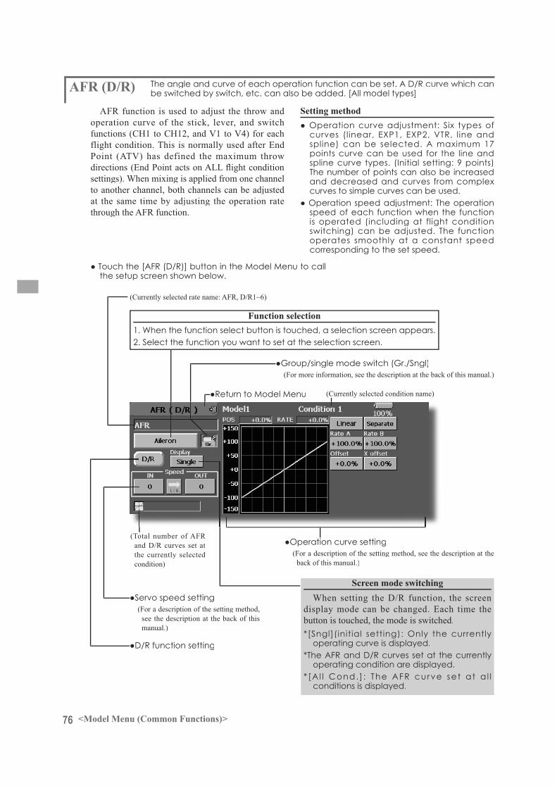
76 <Model Menu (Common Functions)>
the setup screen shown below.
AFR function is used to adjust the throw and operation curve of the stick, lever, and switchfunctions (CH1 to CH12, and V1 to V4) for each flight condition. This is normally used after End Point (ATV) has defined the maximum throw
settings). When mixing is applied from one channel to another channel, both channels can be adjusted at the same time by adjusting the operation ratethrough the AFR function.
points curve can be used for the line and spline curve types. (Initial setting: 9 points) The number of points can also be increased and decreased and curves from complex curves to simple curves can be used.
speed of each function when the function is operated (including at flight condition switching) can be adjusted. The function operates smoothly at a constant speed corresponding to the set speed.
(Currently selected condition name)
(Currently selected rate name: AFR, D/R1~6)
Function selection
(Total number of AFR and D/R curves set at the currently selected condition)
(For a description of the setting method, see the description at the back of thismanual.)
When setting the D/R function, the screendisplay mode can be changed. Each time thebutton is touched, the mode is switched.
operating curve is displayed.
operating condition are displayed.
conditions is displayed.
(For more information, see the description at the back of this manual.)
(For a description of the setting method, see the description at the back of this manual.)
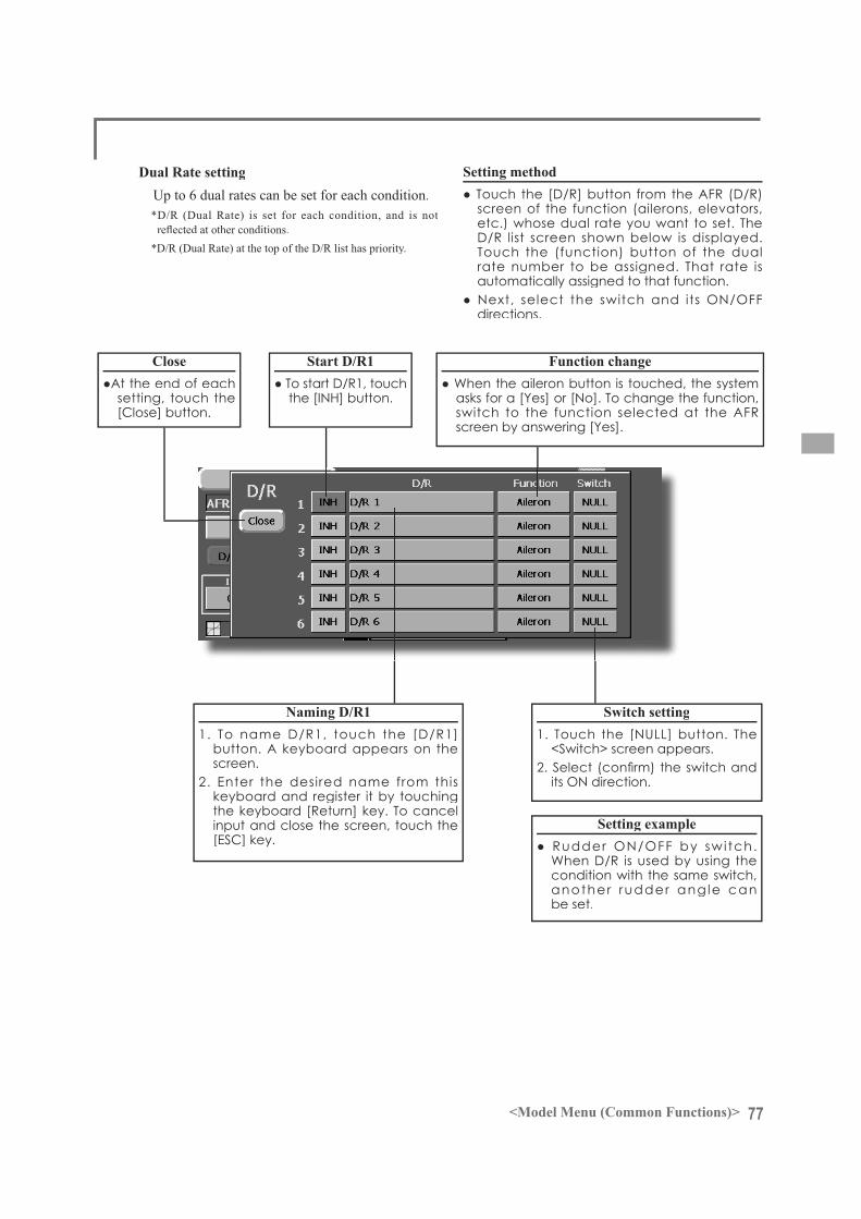
77<Model Menu (Common Functions)>
Up to 6 dual rates can be set for each condition.*D/R (Dual Rate) is set for each condition, and is not
*D/R (Dual Rate) at the top of the D/R list has priority.
screen of the function (ailerons, elevators,etc.) whose dual rate you want to set. The
Touch the (function) button of the dualrate number to be assigned. That rate isautomatically assigned to that function.
directions.
Close
setting, touch the
screen.2. Enter the desired name from this
input and close the screen, touch the
its ON direction.
condition with the same switch, another rudder ang le can be set.

78 <Model Menu (Common Functions)>
call the setup screen shown below.
Program mixing which can be freely customized. Up to 10 mixings can be used for
Programmable mixing may be used to correct undesired tendencies of the aircraft, and it may also be used for unusual control configurations. Mixing means that the motion of a command channel, called the "master," controls the motion of the mixed channel,called "slave."
You may choose to have the Masters trim added to the Slave channel response, if you desire ("Trim"setting). The mixing curve can be changed so that the undesired tendencies can be corrected effectively by setting the LINEAR1/LINEAR2/EXP1/EXP2/VTR/LINE/SPLINE modes. The Delay function can be programmed for each rate. The Delay is used to change the rate smoothly when switching. You may define Mixing ON/OFF switch, control or you may choose to
have mixing remaining on all the time.Offset-type mixing applies a fixed offset or preset
to the programmed channel servo operation and may control up to four circuits simultaneously.
The Programmable mixing includes a link function, which allows Programmable mixing to be linked with the special mixing functions, or with other programmable mixing functions. The link function can be set up for Master and Slave channel individually.
The slave channel AFR mode (STK-STK mode)may be selected, where the slave channel AFR and D/R settings are observed when Link function is set.
circuit. (Fine tune function)
After this function was activated, themaster and slave function names (or offset mixing) are displayed.
(For more information, see the description at the back of this manual.)
(Timer mode)
(Normal mode )
The on time (start/stop time) can be set up to 9 seconds. It is useful for landing gear control of the jet or scale plane, etc.
79<Model Menu (Common Functions)>
conditions:
*Each time the button is touched, it toggles between the Gr. and Sngl modes.
Using the offset mode:
Offset mode.*Each time the button is touched, it toggles between the Mix
and Offset modes.
1. Touch the button of the mixing you want to set. The mixing setup screen is displayed.
button.*Each time this button is touched, it toggles between [INH]
and [ON/OFF].
direction switching*An ON/OFF switch is not set even when the function is
activated.
and its ON direction.*For a description of the selection method, see [Switch
Setting Method] at the back of this manual.
mixing)
menu and select the master channel.
button at the left of the master channel and
*Each time the button is touched, it toggles between mixing direction + and - and "No display" (no link).
*Master channel control can be set to stick, VR, and other simple travels which do not include ATV, AFR, D/R, mixing setting, etc. In this case, display the <Switch> screen by touching the [H/W] button and then select master channel side control.
menu and select the slave channel.
the button at the right-hand side of the slave
*Each time the button is pressed, it toggles between mixing direction + and - and "No display" (no link).
button on the screen.*When mixing includes master side trim, set the Trim button
to [ON]. When mixing does not include master side trim, set the Trim button to [OFF].
*Each time this button is pressed, it toggles between [ON] and [OFF].
*This is effective when the master channel is set by Function.
*Each time this button is pressed, it toggles between [ON] and [OFF].
*This is effective when making corrections when the fuselage is the same but the rudder angles are substantially different.
1. Touch the curve type selection button of the curve type you want to use to display the selection screen and then select the curve you want to use.*For a description of the curve setting method, see the
description at the back of this manual.
the description at the back of this manual.
is displayed.*For a description of the servo speed setting method, see the
description at the back of this manual.*Offset mixing changes the speed. Use the Speed In and
Speed Out buttons to readjust the speed.. The mixing switch can set a delay with a different rate at starting and stopping.
*This function is inactive when a mixing switch is not set.
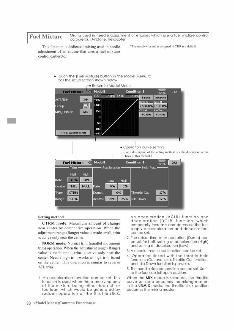
80 <Model Menu (Common Functions)>
Maximum amount of changenear center by center trim operation. When the adjustment range (Range) value is made small, trim is active only near the center.
Normal trim (parallel movement trim) operation. When the adjustment range (Range)value is made small, trim is active only near thecenter. Needle high trim works as high trim based on the center. This operation is similar to reverseATL trim.
function is used when there are symptoms of the mixture being either too r ich or too lean, which would be generated by
temporarily increase and decrease the fuel supply at acceleration and deceleration, can be set.
and setting at deceleration (Low).
to the fuel side full open position.MIX mode is selected, the throttle
curve set data becomes the mixing master.In the UNMIXbecomes the mixing master.
call the setup screen shown below.
This function is dedicated mixing used in needle adjustment of an engine that uses a fuel mixturecontrol carburetor.
*The needle channel is assigned to CH9 as a default.
(For a description of the setting method, see the description at the back of this manual.)
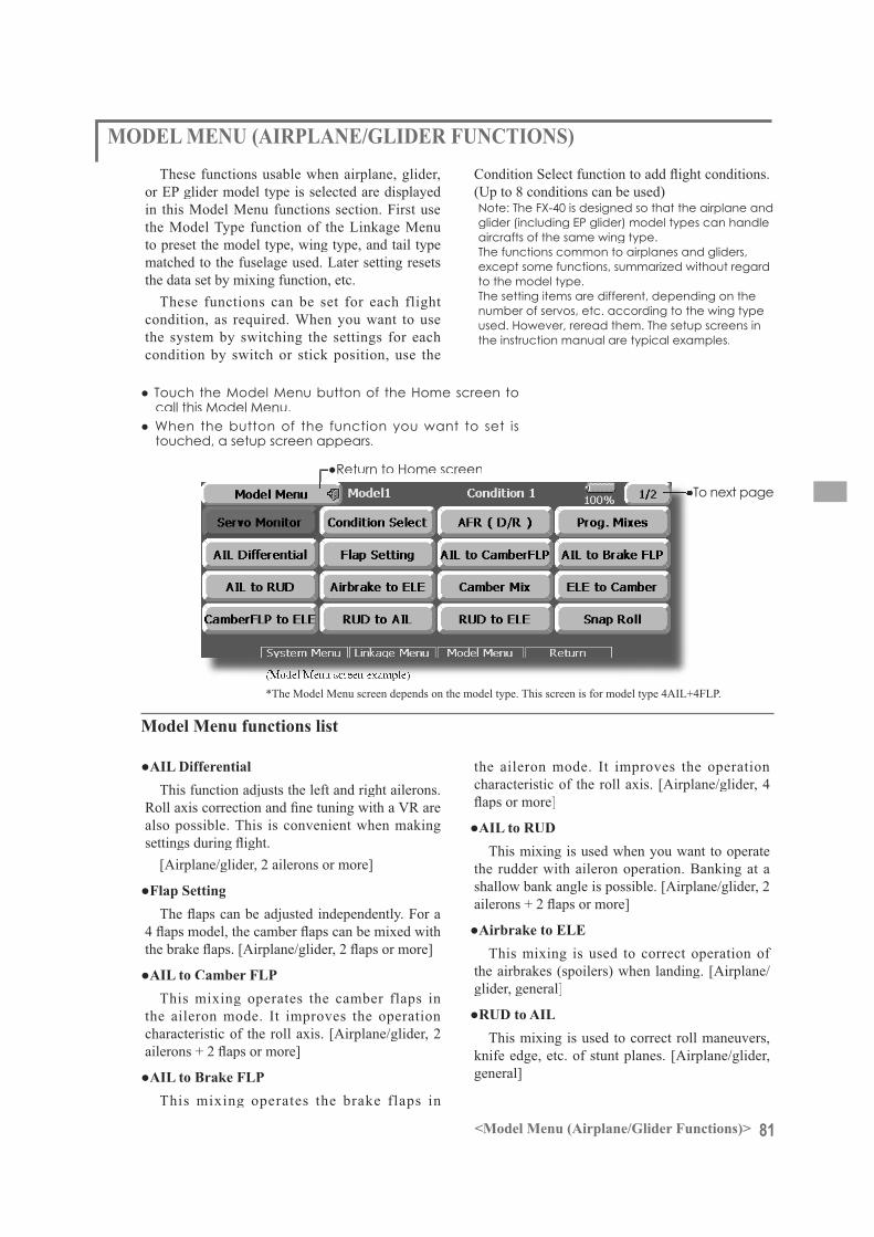
81<Model Menu (Airplane/Glider Functions)>
MODEL MENU (AIRPLANE/GLIDER FUNCTIONS)These functions usable when airplane, glider,
or EP glider model type is selected are displayed in this Model Menu functions section. First use the Model Type function of the Linkage Menu to preset the model type, wing type, and tail typematched to the fuselage used. Later setting resetsthe data set by mixing function, etc.
These functions can be set for each flight condition, as required. When you want to usethe system by switching the settings for eachcondition by switch or stick position, use the
(Up to 8 conditions can be used)Note: The FX-40 is designed so that the airplane and glider (including EP glider) model types can handleaircrafts of the same wing type.The functions common to airplanes and gliders, except some functions, summarized without regard to the model type.The setting items are different, depending on thenumber of servos, etc. according to the wing typeused. However, reread them. The setup screens in the instruction manual are typical examples.
touched, a setup screen appears.
(Model Menu screen example)*The Model Menu screen depends on the model type. This screen is for model type 4AIL+4FLP.
Model Menu functions list
This function adjusts the left and right ailerons.
also possible. This is convenient when making
[Airplane/glider, 2 ailerons or more]
This mixing operates the camber flaps in the aileron mode. It improves the operation characteristic of the roll axis. [Airplane/glider, 2
This mixing operates the brake flaps in
the aileron mode. It improves the operation characteristic of the roll axis. [Airplane/glider, 4
This mixing is used when you want to operate the rudder with aileron operation. Banking at ashallow bank angle is possible. [Airplane/glider, 2
This mixing is used to correct operation of the airbrakes (spoilers) when landing. [Airplane/glider, general]
This mixing is used to correct roll maneuvers,knife edge, etc. of stunt planes. [Airplane/glider,general]

82 <Model Menu (Airplane/Glider Functions)>
AIR BRAKE
AIL 3 (Chip Aileron)
AIL 4 (Chip Aileron)
AIL1(Main Aileron)
AIL 2 (Main Aileron)
FLP 2 (Camber Flap)
FLP 1 (Camber Flap)
ELEVATOR
(ELEVATOR 2)
V-TAIL AILEVATOR
FLP 3 (Brake Flap)
FLP 4 (Brake Flap)
RUDDER 2 Winglet
RUDDER 1
RUDDER(RUDDER 2)
Winglet at Flying wing at Flying wing ( ) ( )
ELEVATOR ELEVATOR 2 (AILERON 5) (AILERON 6)
Adjusts the camber and corrects the elevators. [Airplane/glider, 2 ailerons or more]
elevator operation. Lifting force can be increased at elevators up. [Airplane/glider, 2 ailerons or more]
Used to correct for attitude changes when the
Used when powerful brake operation is necessary. [Glider, 2 ailerons or more]
be called by switch or condition selection. [Glider, 2 ailerons or more]
This is used when airbrakes are necessary when
general)
This is dedicated mixing when a GYA Series gyro is used. [Airplane/glider, general]
Adjusts the elevators and rudder of V-tail models.
Adjusts the elevators and ailerons of models with
Adjusts the left and right rudders of winglet models.
The operation speed when the motor of F5B and other EP gliders is started by switch can be set. [EP glider, general]
This is used to correct roll maneuvers, knife edge, etc. of stunt planes. [Airplane, general]
This selects the snap roll switch and adjusts the steering angle of each rudder. Servo speed can also be adjusted. [Airplane general]
This adjusts the throttles independently when using a
general]
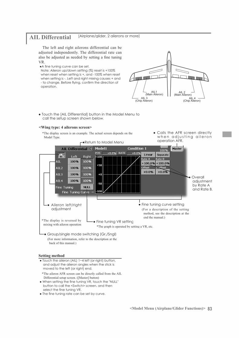
83<Model Menu (Airplane/Glider Functions)>
AIL 3(Chip Aileron)
AIL 4(Chip Aileron)
AIL1(Main Aileron)
AIL 2(Main Aileron)
call the setup screen shown below.
AIL Differential [Airplane/glider, 2 ailerons or more]
The left and right ailerons differential can beadjusted independently. The differential rate can
Note: Aileron up/down setting (%) reset is +100%when reset when setting is +, and -100% when reset when setting is -. Left and right mixing causes + and
operation.
w h e n a d j u s t i n g a i l e r o n
(For more information, refer to the description at the back of this manual.)
adjustment
*The display screen is an example. The actual screen depends on the Model Type.
adjustment
*The display is reversed by mixing with aileron operation
(For a description of the settingmethod, see the description at the end the manual.)
and adjust the aileron angles when the stick is moved to the left (or right) end.
*The aileron AFR screen can be directly called from the AIL Differential setup screen. ([Master] button)
button to call the <Switch> screen, and then
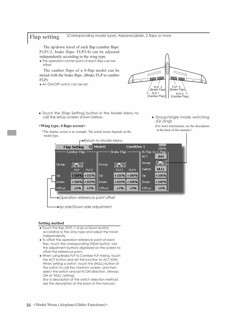
84 <Model Menu (Airplane/Glider Functions)>
FLP 2(Camber Flap)
FLP 1(Camber Flap)
FLP 3(Brake Flap)
FLP 4(Brake Flap)
call the setup screen shown below.
independently according to the wing type.
offset
The camber flaps of a 4-flap model can be
FLP)
(Gr./Sngl)(For more information, see the description
at the back of this manual.)*The display screen is an example. The actual screen depends on themodel type.
according to the wing type and adjust the travel independently.
the adjustment buttons displayed on the screen to offset the reference point.
the switch to call the <Switch> screen, and then
(For a description of the switch selection method, see the description at the back of this manual.)

85<Model Menu (Airplane/Glider Functions)>
AIL 3(Chip Aileron)
AIL 4(Chip Aileron)
AIL1(Main Aileron)
AIL 2(Main Aileron)
FLP 2(Camber Flap)
FLP 1(Camber Flap)
or more
in the aileron mode. When the aileron stick is manipulated, the ailerons and camber flapsperform aileron operation simultaneously and the operation characteristic of the roll axis is improved.
*The display screen is an example. The actual screen depends on the model type.
(For a description of the curve setting method, see the description at the back of this manual.)
servo
(For more information, see the description at the back of this manual.)
a d j u s t m e n t a t
the switch to call the <Switch> screen, and then
(For a description of the switch selection method,see the description at the back of this manual.)
and adjust the mixing rate with the adjustment buttons.
*When the mixing direction is reversed by the linkage, adjustments can be made by changing the mixing rate polarity.
(For a description of the mixing curve settingmethod, see the description at the back of thismanual.)
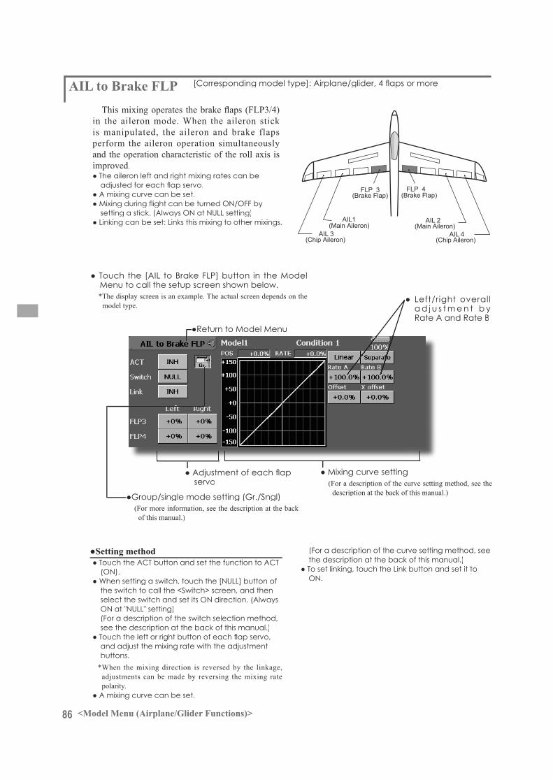
86 <Model Menu (Airplane/Glider Functions)>
AIL 3(Chip Aileron)
AIL 4(Chip Aileron)
AIL1(Main Aileron)
AIL 2(Main Aileron)
FLP 3(Brake Flap)
FLP 4(Brake Flap)
in the aileron mode. When the aileron stick is manipulated, the aileron and brake flapsperform the aileron operation simultaneouslyand the operation characteristic of the roll axis is improved.
*The display screen is an example. The actual screen depends on themodel type.
(For a description of the curve setting method, see the description at the back of this manual.)
servo
(For more information, see the description at the back of this manual.)
a d j u s t m e n t b y
the switch to call the <Switch> screen, and then
(For a description of the switch selection method, see the description at the back of this manual.)
and adjust the mixing rate with the adjustmentbuttons.
*When the mixing direction is reversed by the linkage,adjustments can be made by reversing the mixing ratepolarity.
(For a description of the curve setting method, seethe description at the back of this manual.)
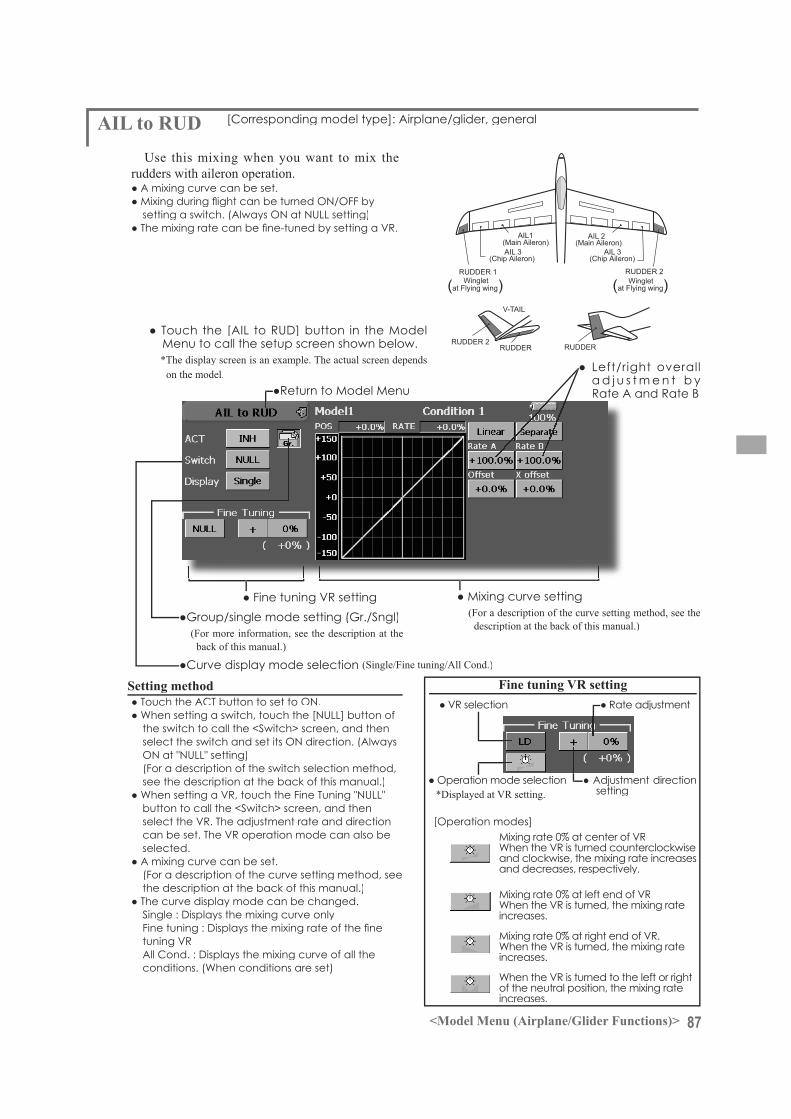
87<Model Menu (Airplane/Glider Functions)>
RUDDER 2RUDDER RUDDER
V-TAIL
RUDDER 2Winglet
RUDDER 1Winglet
at Flying wing at Flying wing( ) ( )
AIL 3 AIL 3(Chip Aileron) (Chip Aileron)
AIL1(Main Aileron)
AIL 2(Main Aileron)
AIL to RUDUse this mixing when you want to mix the
rudders with aileron operation.
*The display screen is an example. The actual screen depends on the model.
(For a description of the curve setting method, see thedescription at the back of this manual.)
(For more information, see the description at the back of this manual.)
a d j u s t m e n t b y
the switch to call the <Switch> screen, and then
(For a description of the switch selection method,see the description at the back of this manual.)
button to call the <Switch> screen, and then
selected.
(For a description of the curve setting method, see the description at the back of this manual.)
(Single/Fine tuning/All Cond.)
and clockwise, the mixing rate increasesand decreases, respectively.
increases.
increases.
of the neutral position, the mixing rateincreases.
setting
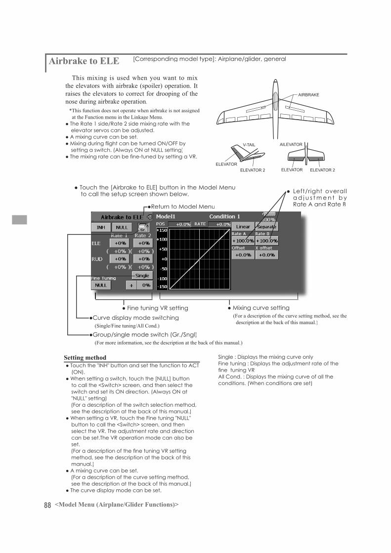
88 <Model Menu (Airplane/Glider Functions)>
AIRBRAKE
ELEVATOR ELEVATOR 2
V-TAIL
ELEVATOR ELEVATOR 2
AILEVATOR
This mixing is used when you want to mixthe elevators with airbrake (spoiler) operation. It raises the elevators to correct for drooping of the nose during airbrake operation.
*This function does not operate when airbrake is not assigned at the Function menu in the Linkage Menu.
elevator servos can be adjusted.
to call the setup screen shown below.
(For a description of the curve setting method, see thedescription at the back of this manual.)(Single/Fine tuning/All Cond.)
a d j u s t m e n t b y
to call the <Switch> screen, and then select the
(For a description of the switch selection method, see the description at the back of this manual.)
button to call the <Switch> screen, and then
set.
method, see the description at the back of this manual.)
(For a description of the curve setting method, see the description at the back of this manual.)
(For more information, see the description at the back of this manual.)
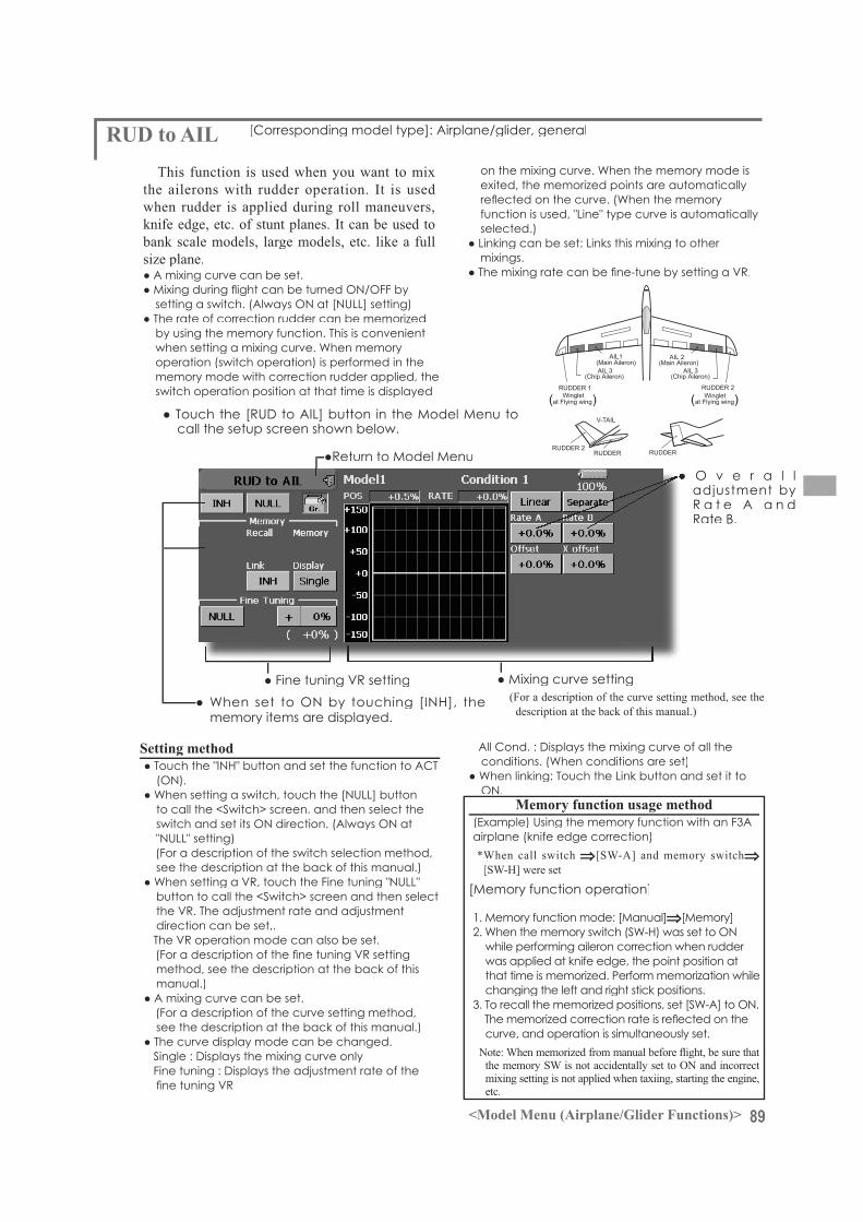
89<Model Menu (Airplane/Glider Functions)>
RUDDER 2RUDDER RUDDER
V-TAIL
RUDDER 2Winglet
RUDDER 1Winglet
at Flying wing at Flying wing( ) ( )
AIL 3 AIL 3(Chip Aileron) (Chip Aileron)
AIL1(Main Aileron)
AIL 2(Main Aileron)
RUD to AILThis function is used when you want to mix
the ailerons with rudder operation. It is used when rudder is applied during roll maneuvers, knife edge, etc. of stunt planes. It can be used tobank scale models, large models, etc. like a fullsize plane.
by using the memory function. This is convenient
operation (switch operation) is performed in the memory mode with correction rudder applied, the switch operation position at that time is displayed
call the setup screen shown below.
(For a description of the curve setting method, see thedescription at the back of this manual.)memory items are displayed.
adjustment by
exited, the memorized points are automatically
selected.)
mixings.
to call the <Switch> screen, and then select the
(For a description of the switch selection method,see the description at the back of this manual.)
button to call the <Switch> screen and then select
direction can be set,.
method, see the description at the back of thismanual.)
(For a description of the curve setting method,see the description at the back of this manual.)
(Example) Using the memory function with an F3Aairplane (knife edge correction)*When call switch [SW-A] and memory switch
[SW-H] were set
while performing aileron correction when rudder was applied at knife edge, the point position atthat time is memorized. Perform memorization whilechanging the left and right stick positions.
curve, and operation is simultaneously set.
the memory SW is not accidentally set to ON and incorrect mixing setting is not applied when taxiing, starting the engine,etc.

90 <Model Menu (Airplane/Glider Functions)>
This function adjusts the AFR (D/R) rate of camber operation (ailerons, camber flaps, brakeflaps) in the negative and positive directions. The aileron, flap, and elevator rates can also beadjusted independently by curve, and attitude changes can be corrected.
*Initial setting assigns camber operation to side lever LST.
the mixing direction is reversed by the linkage, adjustments can be made by changing the mixing rate polarity.
screen shown below.*The display screen is an example. The actual screen depends on the model type.)
be set.
(For more information, see the description at the back of this manual.)
(For a description of the setting method, refer to the AFR function.)
(For a description of the curve setting method, see thedescription at the back of this manual.)
(For a description of the setting method, see the description at the back of this manual.)
adjustment
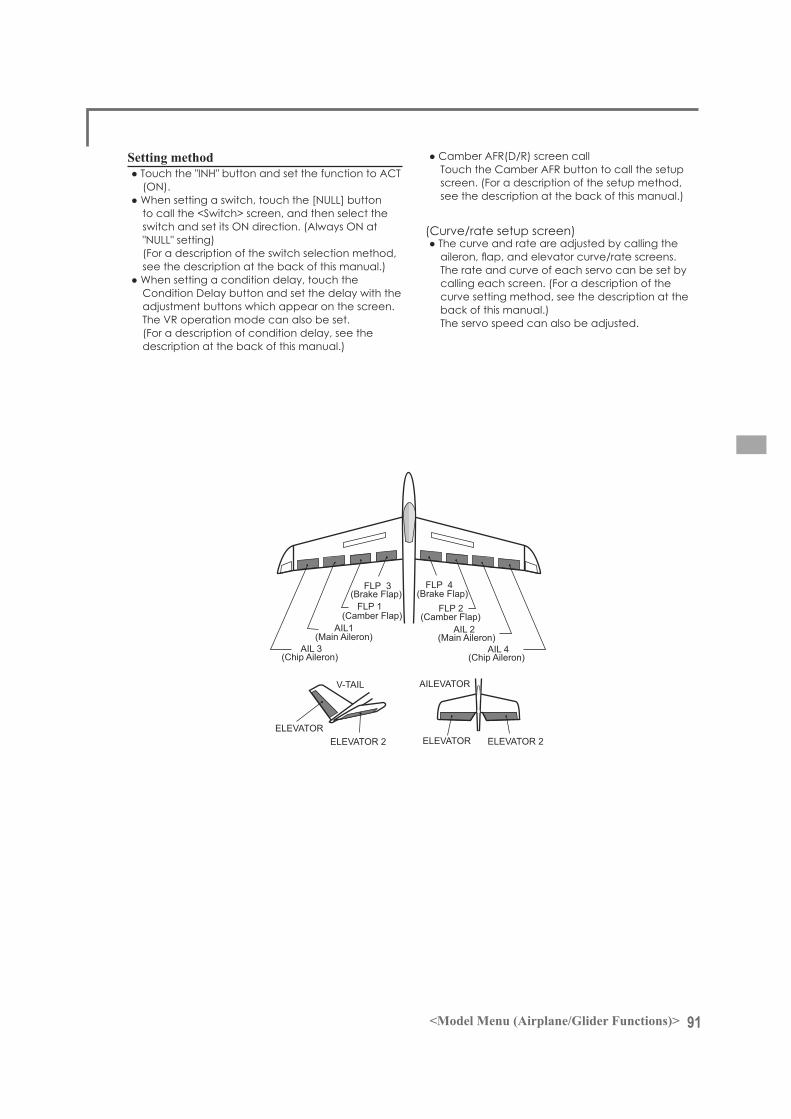
91<Model Menu (Airplane/Glider Functions)>
AIL 3 (Chip Aileron)
AIL 4 (Chip Aileron)
AIL1(Main Aileron)
AIL 2 (Main Aileron)
FLP 2 (Camber Flap)
FLP 1 (Camber Flap)
ELEVATOR ELEVATOR 2
V-TAIL
ELEVATOR ELEVATOR 2
AILEVATOR
FLP 3 (Brake Flap)
FLP 4 (Brake Flap)
to call the <Switch> screen, and then select the
(For a description of the switch selection method, see the description at the back of this manual.)
adjustment buttons which appear on the screen.
(For a description of condition delay, see the description at the back of this manual.)
screen. (For a description of the setup method, see the description at the back of this manual.)
The rate and curve of each servo can be set by calling each screen. (For a description of the curve setting method, see the description at the back of this manual.)The servo speed can also be adjusted.
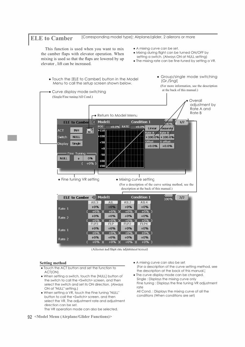
92 <Model Menu (Airplane/Glider Functions)>
This function is used when you want to mix the camber flaps with elevator operation. When
elevator , lift can be increased.
(Single/Fine tuning/All Cond.)
(Gr./Sngl)(For more information, see the description
at the back of this manual.)
(For a description of the curve setting method, see thedescription at the back of this manual.)
adjustment by
the switch to call the <Switch> screen, and then
button to call the <Switch> screen, and then
direction can be set.
(For a description of the curve setting method, seethe description at the back of this manual.)
rate
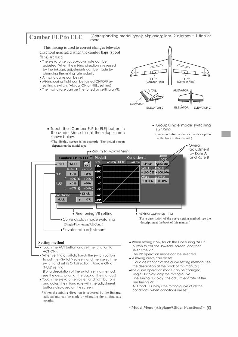
93<Model Menu (Airplane/Glider Functions)>
ELEVATOR ELEVATOR 2
V-TAIL
ELEVATOR ELEVATOR 2
AILEVATOR
FLP 2 (Camber Flap)
FLP 1 (Camber Flap)
(For a description of the curve setting method, see thedescription at the back of this manual.)
more
This mixing is used to correct changes (elevator
by the linkage, adjustments can be made bychanging the mixing rate polarity.
shown below.*The display screen is an example. The actual screen
depends on the model type.
(Single/Fine tuning/All Cond.)
(Gr./Sngl)(For more information, see the description
at the back of this manual.)
adjustment
to call the <Switch> screen, and then select the
(For a description of the switch setting method, see the description at the back of the manual.)
and adjust the mixing rate with the adjustment buttons displayed on the screen.
*When the mixing direction is reversed by the linkage,adjustments can be made by changing the mixing ratepolarity.
button to call the <Switch> screen, and then
(For a description of the curve setting method, see the description at the back of this manual.)
conditions (when conditions are set)
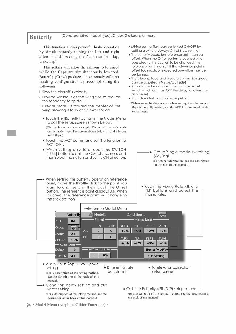
94 <Model Menu (Airplane/Glider Functions)>
This function allows powerful brake operation by simultaneously raising the left and right ailerons and lowering the flaps (camber flap,
This setting will allow the ailerons to be raised while the flaps are simultaneously lowered.
landing configuration by accomplishing the
1. Slow the aircraft’s velocity.2. Provide washout at the wing tips to reduce
the tendency to tip stall.
operated to the position to be changed, the
offset too much, unexpected operation may beperformed.
also be set.
*When servo binding occurs when setting the ailerons and
rudder angle.
point, move the throttle stick to the point you
touched, the reference point will change tothe stick position.
adjustment setup screen
(For a description of the setting method, see the description at the back of this manual.)
setting(For a description of the setting method,
see the description at the back of thismanual.)
switch setting(For a description of the setting method, see the
description at the back of this manual.)
(Gr./Sngl)(For more information, see the description
at the back of this manual.)
FLP buttons and adjust themixing rates.
to call the setup screen shown below.(The display screen is an example. The actual screen depends
on the model type. The screen shown below is for 4 ailerons
[NULL] button to call the <Switch> screen, and

95<Model Menu (Airplane/Glider Functions)>
AIL 3 (Chip Aileron)
AIL 4 (Chip Aileron)
AIL1(Main Aileron)
AIL 2 (Main Aileron)
FLP 2 (Camber Flap)
FLP 1 (Camber Flap)
ELEVATOR ELEVATOR 2
V-TAIL
ELEVATOR ELEVATOR 2
AILEVATOR
FLP 3 (Brake Flap)
FLP 4 (Brake Flap)
([ELE Setup] screen)
adjust the rates with the adjustment buttons displayed on the screen.
(For a description of the curve setting method, see the description at the back of this manual.)
(For a description of the setting method, see thedescription at the back of this manual.)

96 <Model Menu (Airplane/Glider Functions)>
These functions call the ailerons, elevators, and
The amount of ailerons, elevator, and flaps
a switch.As an example can be set up for
and a slight amount of up elevator.can be used for high speed flying, with both
of down elevator.The trim functions can be activated during
can be set to provide a smooth transition betweenthe two. Trim Mix 2 will have priority over TrimMix 1.
Touch the corresponding button and adjust the rate with the adjustment buttons displayed on the screen.
offset rate can be adjusted.Touch the corresponding buttonand adjus t the rate wi th theadjustment buttons displayed onthe screen.
call the setup screen shown below.(The display screen is an example. The actual screen depends on the
(Touch the [1/2] button to switch to page 2.)
to call the <Switch> screen, and then select the
setting)(For a description of the switch selection method, see the description at
the back of this manual.)
*When separating the settings for each condition, touch thegroup mode button and set it to [Sngl].
switch can be linked to a stick, etc.<Speed>
<Fine Tuning>The offset rate can be varied in the Fine Tuning
selection.
operation can be interrupted and each rudder quickly returned to its original position by selecting acut switch.

97<Model Menu (Airplane/Glider Functions)>
AIL 3 (Chip Aileron)
AIL 4 (Chip Aileron)
AIL1(Main Aileron)
AIL 2 (Main Aileron)
FLP 2 (Camber Flap)
FLP 1 (Camber Flap)
ELEVATOR ELEVATOR 2
V-TAIL
ELEVATOR ELEVATOR 2
AILEVATOR
FLP 3 (Brake Flap)
FLP 4 (Brake Flap)
(Gr./Sngl)(Fo r more i n fo rma t ion , s ee t he
description at the back of this manual.)
button to call the <Switch> screen.
description of the setting method, see the description at the back of this manual) and cut switch setting.
speed setting(For a description of the setting method, see the
description at the back of this manual.)
Auto: Trim mix function call can be linked to a stick,etc. A stick switch, etc. separate from the function
(Trim mix setup page 2/2)
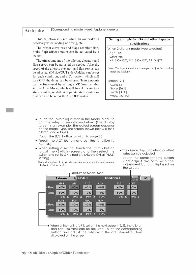
98 <Model Menu (Airplane/Glider Functions)>
This function is used when an air brake isnecessary when landing or diving, etc.
The preset elevators and flaps (camber flap,brake flap) offset amount can be activated by aswitch.
The offset amount of the aileron, elevator, and flap servos can be adjusted as needed. Also the
be adjusted. (IN side/OUT side) A delay can be set for each condition, and a Cut switch which will turn OFF the delay can be chosen. Trim amounts
set the Auto Mode, which will link Airbrake to astick, switch, or dial. A separate stick switch or dial can also be set as the ON/OFF switch.
button and adjust the rates with the adjustment buttons displayed on the screen.
rates can be adjusted.Touch the corresponding buttonand adjus t the rate wi th theadjustment buttons displayed onthe screen.
call the setup screen shown below. (The displayscreen is an example. The actual screen dependson the model type. The screen shown below is for 4
(Touch the [1/2] button to switch to page 2.)
to call the <Switch> screen, and then select the
setting)(For a description of the switch selection method, see the description at
the back of this manual.)
(Page 1/2)
match the fuselage.
(Screen 2/2)
Group: [Sngl]
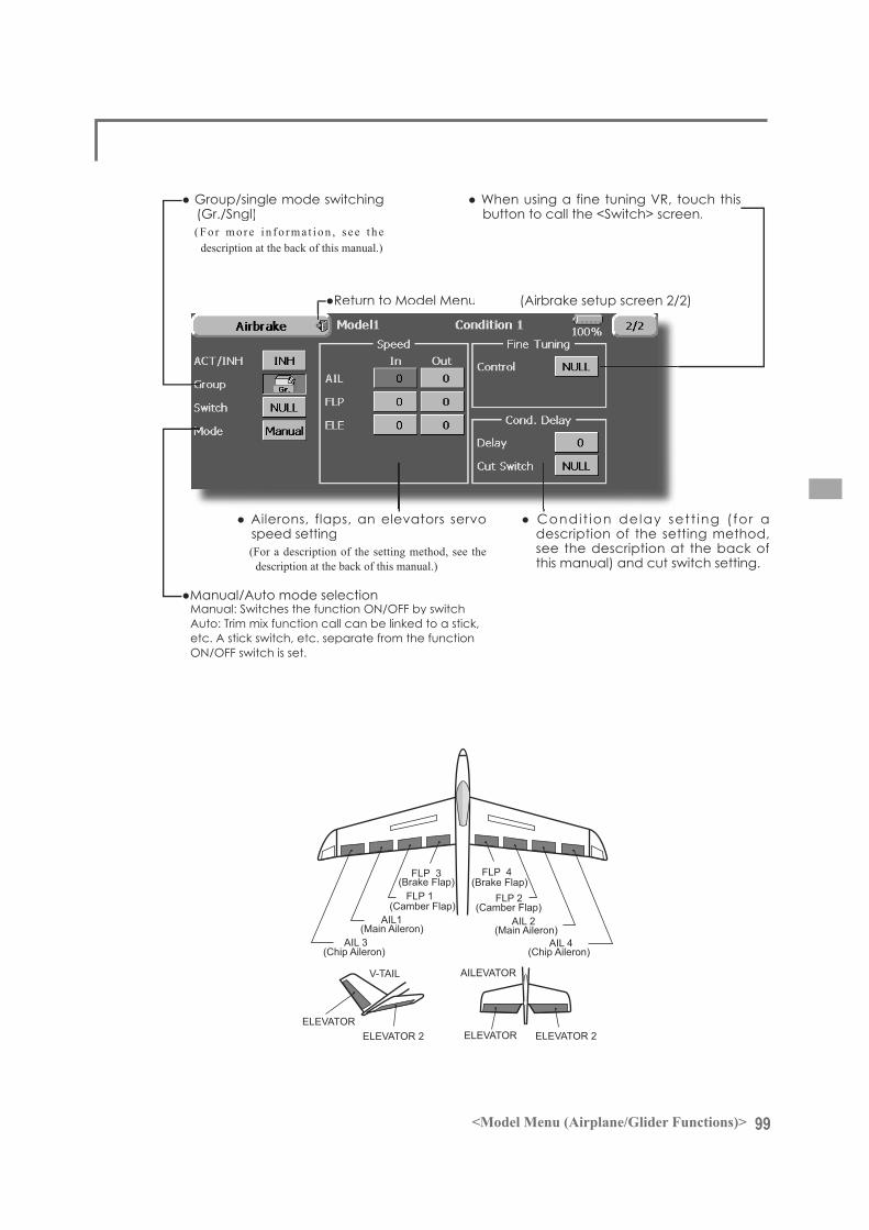
99<Model Menu (Airplane/Glider Functions)>
AIL 3 (Chip Aileron)
AIL 4 (Chip Aileron)
AIL1(Main Aileron)
AIL 2 (Main Aileron)
FLP 2 (Camber Flap)
FLP 1 (Camber Flap)
FLP 3 (Brake Flap)
FLP 4 (Brake Flap)
ELEVATOR ELEVATOR 2
V-TAIL
ELEVATOR ELEVATOR 2
AILEVATOR
(Gr./Sngl)(Fo r more i n fo rma t ion , s ee t h e
description at the back of this manual.)
button to call the <Switch> screen.
description of the setting method, see the description at the back of this manual) and cut switch setting.
speed setting(For a description of the setting method, see the
description at the back of this manual.)
Auto: Trim mix function call can be linked to a stick,etc. A stick switch, etc. separate from the function
(Airbrake setup screen 2/2)
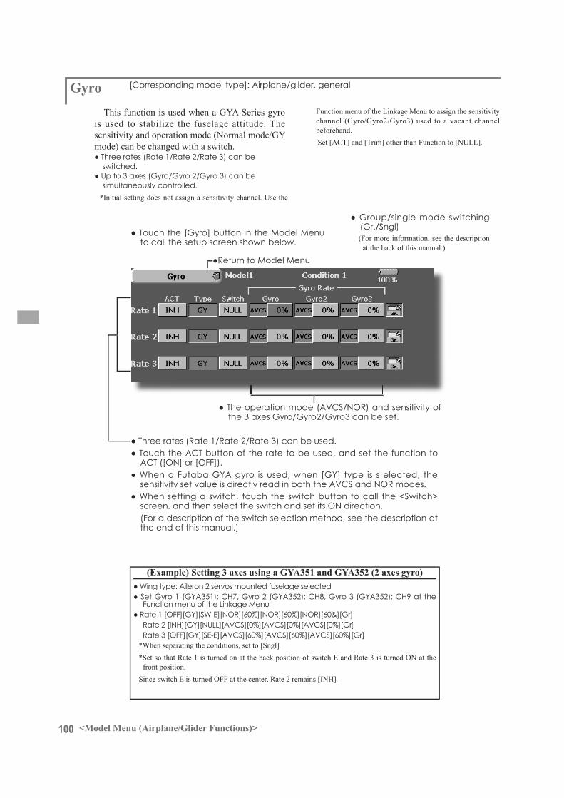
100 <Model Menu (Airplane/Glider Functions)>
is used to stabilize the fuselage attitude. The
mode) can be changed with a switch.
switched.
simultaneously controlled.*Initial setting does not assign a sensitivity channel. Use the
to call the setup screen shown below.
Function menu of the Linkage Menu to assign the sensitivity
beforehand. Set [ACT] and [Trim] other than Function to [NULL].
the 3 axes Gyro/Gyro2/Gyro3 can be set.
(Gr./Sngl)(For more information, see the description
at the back of this manual.)
(For a description of the switch selection method, see the description atthe end of this manual.)
*When separating the conditions, set to [Sngl].
front position.Since switch E is turned OFF at the center, Rate 2 remains [INH].

101<Model Menu (Airplane/Glider Functions)>
ELEVATOR(RUDDER 2)
RUDDER(ELEVATOR 2)
V-TAIL
This function let’s you adjust for left and right rudder angle changes during elevator and rudder
control rudder movement as Elevators. In addition to each rudder side moving up and down together, each side moves in opposite directions when
as a Ruddervator, as they can serve the same purpose.
to call the setup screen shown below.
rudder operation
(Gr./Sngl)(For more information, see the description
at the back of this manual.)
(Elevator function)
elevator operation

102 <Model Menu (Airplane/Glider Functions)>
ELEVATOR ELEVATOR 2(AILERON 5) (AILERON 6)
(Effective only when 2 servos used at the elevators)
This function improves the operating performance of the roll axis by operating the elevators as ailerons.
Ailevator is where each elevator in a standard (conventional) or v-tail moves independently, like ailerons on a wing. In addition to each elevator side moving up and down together, each side moves inopposite directions when moving as an Ailevator. On
can serve the same purpose. Typically, both Ailevator and ailerons are coupled together to maximize rollperformance, especially on larger wingspan planes..
the Function menu.
call the setup screen shown below.
(Aileron function)
of the left and right elevators can be adjusted.
(Gr./Sngl)(For more information, see the description
at the back of this manual.)
(Elevator function)
when the elevator st ick is manipulated can beindividually adjusted.

103<Model Menu (Airplane/Glider Functions)>
RUDDER 1Winglet
at Flying wing( )
RUDDER 2Winglet
at Flying wing( )
This function adjusts the rubber left and right
Winglets are used to improve the efficiency of aircraft lowering the lift-induced drag caused by wingtip vortices. The winglet is a vertical or angled extension at the tips of each wing.
Winglets work by increasing the effective aspect ratio wing without adding greatly to the structuralstress and hence necessary weight of its structure - an extension of wing span would also permit lowering of induced drag, though it would cause parasitic drag and would require boosting the strength of the wing and hence its weight - there would come a point at which no overall useful saving would be made. A winglet helps to solve this by effectively increasing the aspect ratio without adding to the span of the wing.
be individually set.
(Gr./Sngl)(For more information, see the description
at the back of this manual.)

104 <Model Menu (Airplane/Glider Functions)>
MotorThis function lets you set the operation speed
when the motor of a F5B or other EP glider is started by switch. The operation speed can be set in 2 ranges of slow speed flight and high speed
operated as a safety function by setting 2 switches.
be adjusted independently in 2 ranges (Speed 1/Speed 2).
(From Speed 1 to Speed 2)
activated at initial operation only. (1 timeoperation) However, operation can be repeated
to call the setup screen shown below.
The Speed 1 and Speed 2 region boundarycan be changed,
The speed when Speed 1 and Speed 2 are
Touch the button and set the function to
(For more information, see the descriptionat the back of this manual.)
A switch that turns the function itself
[Yes] and [No] are displayed by touching
touched, the direction of the motor switch
direction also changes.
Notes
amp used.

105<Model Menu (Airplane/Glider Functions)>
RUD to ELEThis function is used when you want to mix
elevator with rudder operation. It is used to correct undesirable tendencies when rudder is applied inroll maneuvers, knife edge, etc. of stunt planes.
call the setup screen shown below.
(For a description of the curve setting method, see the description at the back of this manual.)
items are displayed.
operation (switch operation) is performed with
the stick position at that time is displayed on the
(Fine tuning)
adjustment
(For more information, see the description at the back of this manual.)
to call the <Switch> screen, and then select the
(For a description of the switch setting method, see the description at the back of this manual.)
button to call the <Switch> screen, and then
direction can be set.
method, see the description at the back of this manual.)
(Example) Using the memory function with an F3Aairplane (knife edge correction)*When call switch [SW-A] and memory switch
[SW-H] were set
while performing elevator correction whenrudder was applied at knife edge, the point
is performed while changing the left and right stick positions.
curve, and operation is simultaneously set.
the memory SW is not accidentally set to ON and incorrect mixing setting is not applied when taxiing, starting the engine, etc.

106 <Model Menu (Airplane/Glider Functions)>
Snap RollThis function selects the switch and rate
adjustment of rudder, ailerons, elevators, or flaps when a snap roll is performed.
right/down, left/up, left/down)
switch in the state in which the direction switch was switched to the direction in which you want
roll in each direction can be executed by means of independent switches.
the switch can be set so that snap roll is not executed when, for instance, the landinggear is lowered, even if the switch is turned onaccidentally. The snap roll switch is activated only
executing snap roll)
*The snap roll up side left and right and down side left and right direction switches are selected here.
The operation speed of each control
be changed and snap roll executed by stick while there is switch operation can be performed.
below.
(Single/Fine tuning/All Cond.)(Gr./Sngl)(For more information, see the description
at the back of this manual.)
(For a description of the setting method, see the description at the back of this manual.)
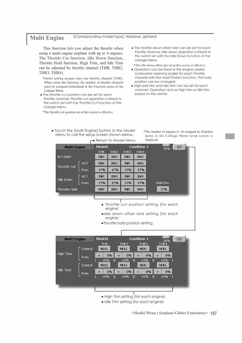
107<Model Menu (Airplane/Glider Functions)>
This function lets you adjust the throttle whenusing a multi engine airplane with up to 4 engines. The Throttle Cut function, Idle Down function,Throttle Hold function, High Trim, and Idle Trimcan be adjusted by throttle channel (THR, THR2,
*Initial setting assigns only one throttle channel (THR).When using this function, the number of throttle channels must be assigned beforehand at the Function menu of theLinkage Menu.
throttle channel. Throttle cut operation is linked to
*The throttle cut position set at this screen is effective.
*The number of engines (1~4) assigned by Functionmenu in the Linkage Menu setup screen is displayed.
*The idle down offset rate set at this screen is effective.
(carburetor opening angle) for each throttlechannel with the Hold Position function. The holdposition can be changed.
based on the center.
engine)
engine)

108 <Model Menu (Helicopter Functions)>
MODEL MENU (HELICOPTER)This section contains information on the
commands that apply to helicopters only. For instructions on Airplanes and Sailplanes, refer to the sections pertaining to those aircraft. Each of these functions can be set independently for
touch the desired function button to be entered. Use the Model Type function in the Linkage
Menu to select the swash type matched to the
helicopter beforehand. If you later change model types, all settings will be lost.
Also, add flight conditions at the ConditionSelect screen before setting the model data at each function. (Up to 8 conditions can be used)
The AFR function, fuel mixture and other functions common to all model types, are described in a separate section.
Model Menu functions (helicopter) list
Condition Hold function
PIT Curve:THR Curve: Throttle curve and hovering trim adjustmentAcceleration: Counteracts torque due to sudden throttle and pitch commandsThrottle Hold: Moves the throttle to idle during autorotationSwash Mix: Compensates for each control responseThrottle Mix: Compensates for power loss when cyclic appliedPit to Needle:Pit to RUD: Handles torque changes from pitch angle inputsFuel Mixture: Commands a second servo to adjust the fuel mixture at the carburetorGyro: Used to switch gyro sensitivityGovernor: Used to switch RPM of the helicopter’s head
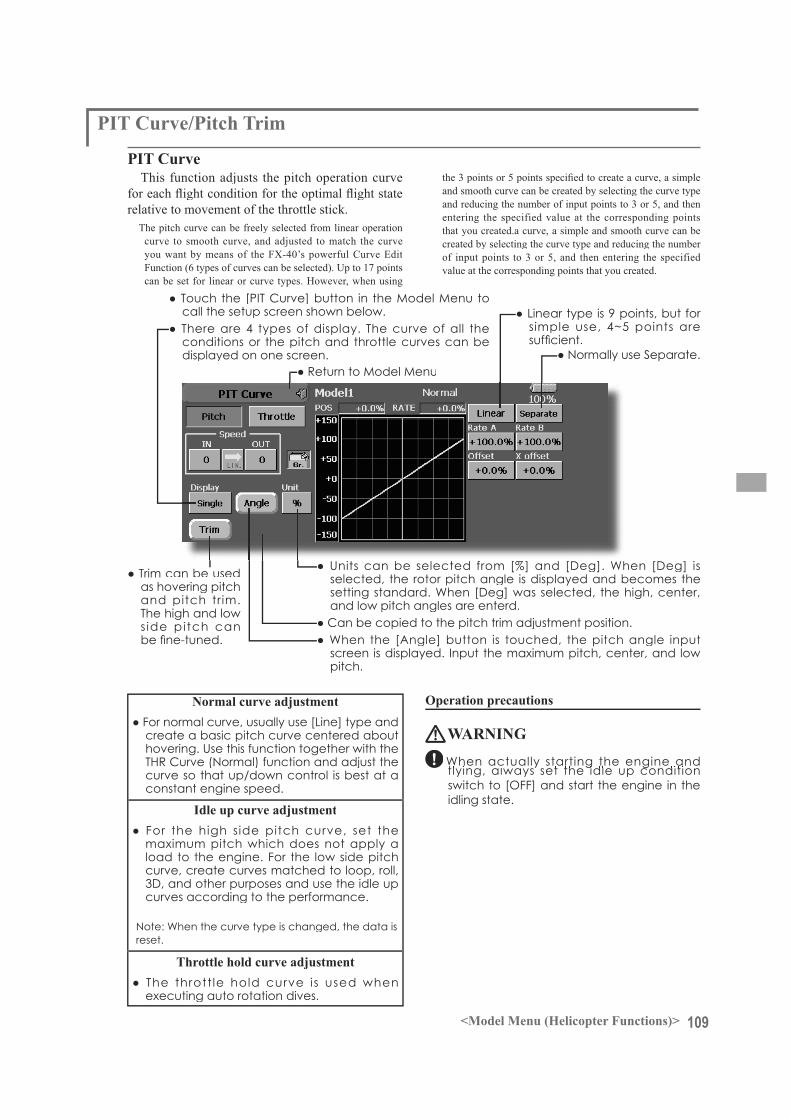
109<Model Menu (Helicopter Functions)>
PIT Curve/Pitch Trim
PIT CurveThis function adjusts the pitch operation curve
relative to movement of the throttle stick.The pitch curve can be freely selected from linear operation
curve to smooth curve, and adjusted to match the curveyou want by means of the FX-40’s powerful Curve Edit Function (6 types of curves can be selected). Up to 17 pointscan be set for linear or curve types. However, when using
and smooth curve can be created by selecting the curve type and reducing the number of input points to 3 or 5, and thenentering the specified value at the corresponding points that you created.a curve, a simple and smooth curve can becreated by selecting the curve type and reducing the number of input points to 3 or 5, and then entering the specified value at the corresponding points that you created.
Normal curve adjustment
Idle up curve adjustment
Throttle hold curve adjustment
Operation precautions
WARNING

110 <Model Menu (Helicopter Functions)>
Normal Curve Idle-up 1 Curve Idle-up 2 Curve Hold Curve
Setting method
The screens shown below are curves created by entering the pitch angle at low, center, and high side 3 points or 5 points at each condition. They werecreated by reducing the number of points to the 3 points of low side, center, and high side. When
by the helicopter (or the reference value).*For a description of the curve setting method, see the
description at the back of this manual.
Curve setting examples
Pitch Trim (Hovering pitch, high pitch, low pitch)The hovering pitch, low pitch, and high pitch trim setup screen can be called from the PIT Curve setup
screen.
(Continued on next page)
111<Model Menu (Helicopter Functions)>
Hovering pitch trimThe Hovering Pitch function trims the pitch near
the hovering point. Normally, it is used with the
tuned for changes in rotor speed accompanying
conditions. Adjust the hovering pitch so that rotor speed is constant. This function can be used together with the Hovering Throttle Trim function for more delicate operation.
Setting method
CTRM mode:
N O R M m o d e :
High Pitch/Low Pitch TrimHigh Pitch/Low Pitch Trim is the pitch servo
high side and low side trim function.
Setting method
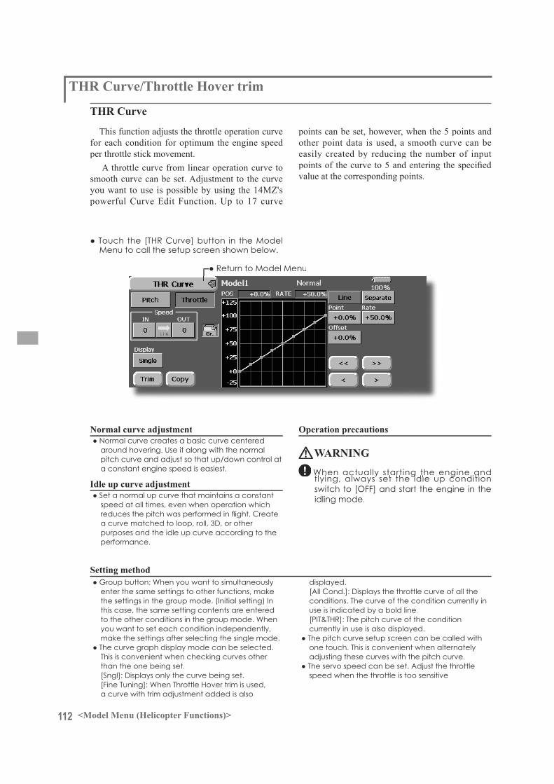
112 <Model Menu (Helicopter Functions)>
THR Curve/Throttle Hover trim
THR Curve
This function adjusts the throttle operation curve for each condition for optimum the engine speed per throttle stick movement.
A throttle curve from linear operation curve tosmooth curve can be set. Adjustment to the curve you want to use is possible by using the 14MZ's powerful Curve Edit Function. Up to 17 curve
points can be set, however, when the 5 points and other point data is used, a smooth curve can beeasily created by reducing the number of input
value at the corresponding points.
Normal curve adjustment
Idle up curve adjustment
Operation precautions
WARNING
Setting method

113<Model Menu (Helicopter Functions)>
Normal Curve Idle-up 1 Curve Idle-up 2 Curve
The curves shown below were created by usingthe Line mode and entering the data of the 5 points0% (low side), 25%, 50% (center), 75%, 100%(high) side at each condition. They were created byreducing the number points of the line to 5. When
actually creating a curve, enter the data specified per the fuselage (or the reference value).
*For a description of the curve creation method, see the description at the back of this manual.
Curve setting examples
Throttle Hover trimThe Throttle Hover trim setup screen can be called from the THR Curve setup screen.
The Throttle Hover function trims the throttlenear the hovering point. Normally, use it withhovering conditions. Changes in rotor speed accompanying changes in the temperature, humidity, and other flight conditions can betrimmed. Adjust the throttle so that rotor rotation ismost stable. More delicate trimming is also possible by using this function along with the Hover Pitchfunction.
Setting method
CTRM mode:
NORM mode:

114 <Model Menu (Helicopter Functions)>
Acceleration MixingThis function is used to adjust the pitch and the
throttle at acceleration/deceleration. An accelerationfunction which temporarily increases the pitch and throttle operations at throttle stick acceleration/deceleration operation can be set.
Example of acceleration function use
Setting method
Note: When using the Acceleration funtion, since the pitch stroke is large, make your settings so there is no binding of your linkage.
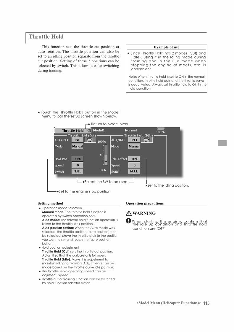
115<Model Menu (Helicopter Functions)>
Throttle HoldThis function sets the throttle cut position at
auto rotation. The throttle position can also beset to an idling position separate from the throttlecut position. Setting of these 2 positions can beselected by switch. This allows use for switchingduring training.
Example of use
Setting method
Manual mode:
Auto mode:
Auto position setting:
Throttle Hold (Cut)
Throttle Hold (Idle):
Operation precautions
WARNING

116 <Model Menu (Helicopter Functions)>
Swash mixingThe swash mix function is used to correct the
swash plate in the aileron (roll) direction and elevator (cyclic pitch) corresponding to each operation of each condition.
Adjustment by independent curve for aileron,elevator, and pitch operations is possible. Theoperation can be smoothly adjusted by calling upthe “Curve setup” screen by touching the buttonthat corresponds to the mixing and direction which needs correction.
Example of use
Setting method
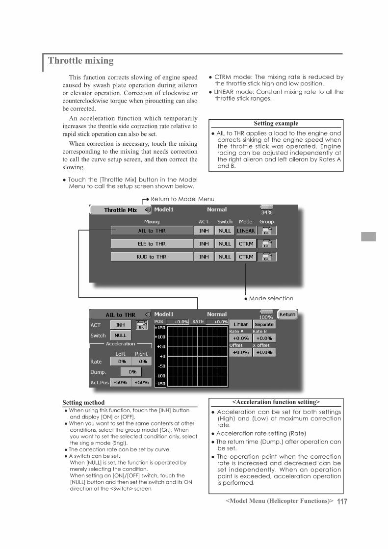
117<Model Menu (Helicopter Functions)>
Throttle mixingThis function corrects slowing of engine speed
caused by swash plate operation during aileronor elevator operation. Correction of clockwise or counterclockwise torque when pirouetting can alsobe corrected.
An acceleration function which temporarilyincreases the throttle side correction rate relative torapid stick operation can also be set.
When correction is necessary, touch the mixing corresponding to the mixing that needs correctionto call the curve setup screen, and then correct theslowing.
Setting example
Setting method <Acceleration function setting>
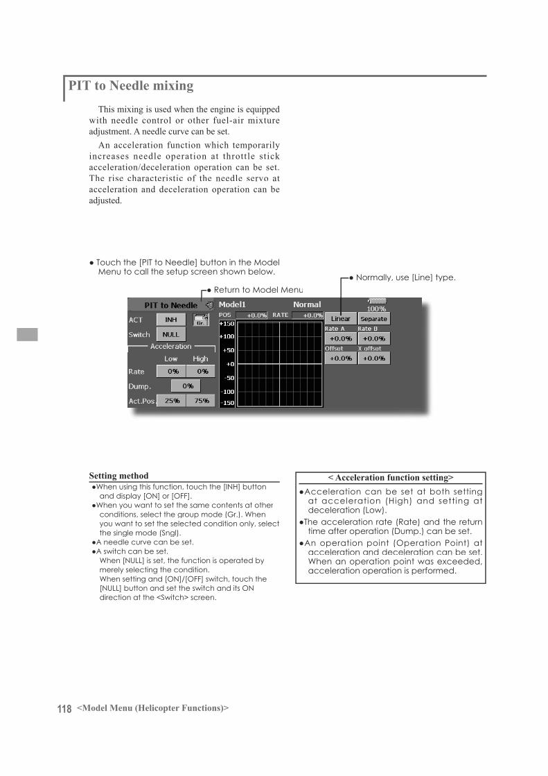
118 <Model Menu (Helicopter Functions)>
PIT to Needle mixingThis mixing is used when the engine is equipped
with needle control or other fuel-air mixtureadjustment. A needle curve can be set.
An acceleration function which temporarily increases needle operation at throttle stick acceleration/deceleration operation can be set. The rise characteristic of the needle servo at acceleration and deceleration operation can be adjusted.
Setting method < Acceleration function setting>

119<Model Menu (Helicopter Functions)>
PIT to RUD mixing (Revolution mixing)Use this mixing when you want to suppress the
torque generated by main rotor pitch and speed changes at pitch operation. Adjust so that the nose does not move in the rudder direction.
An acceleration function which temporarilyincreases the correction rate at throttle stick acceleration/deceleration operation can be set. Themixing rate at acceleration/deceleration can be set.
Setting method
<Normal condition mixing curve>
*Repeat climbing and diving from hovering at a constant rate matched to your own rhythm and adjust the pitch sothat the nose does not deflect when the throttle is raised and lowered.
However, when a GY Series or other headinghold gyro is used, since correction is performed bythe gyro, this mixing is not used. If this function isused when the gyro operation mode is the AVCS mode, the neutral position will change.
<Idle up condition mixing curve>
<Acceleration function setting>
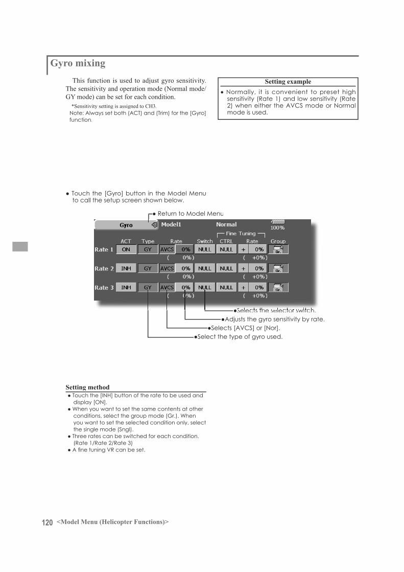
120 <Model Menu (Helicopter Functions)>
Gyro mixingThis function is used to adjust gyro sensitivity.
The sensitivity and operation mode (Normal mode/GY mode) can be set for each condition.
*Sensitivity setting is assigned to CH3.
Setting method
Setting example
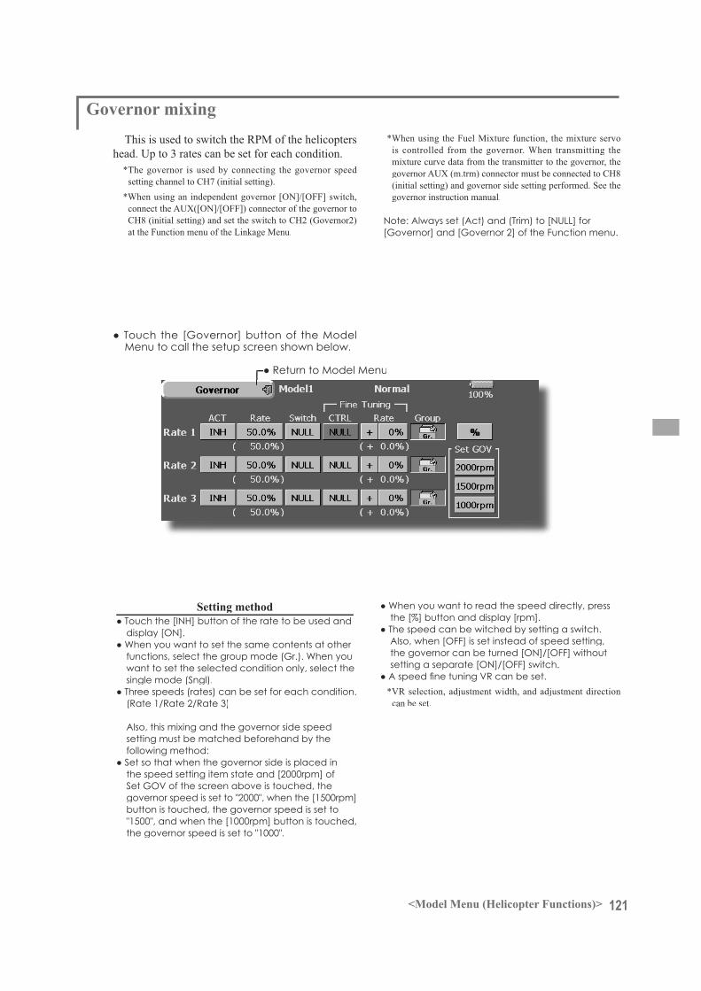
121<Model Menu (Helicopter Functions)>
Governor mixingThis is used to switch the RPM of the helicopters
head. Up to 3 rates can be set for each condition.*The governor is used by connecting the governor speed
setting channel to CH7 (initial setting).*When using an independent governor [ON]/[OFF] switch,
connect the AUX([ON]/[OFF]) connector of the governor to CH8 (initial setting) and set the switch to CH2 (Governor2)at the Function menu of the Linkage Menu.
Setting method
*When using the Fuel Mixture function, the mixture servo is controlled from the governor. When transmitting themixture curve data from the transmitter to the governor, thegovernor AUX (m.trm) connector must be connected to CH8(initial setting) and governor side setting performed. See thegovernor instruction manual.
*VR selection, adjustment width, and adjustment direction can be set.
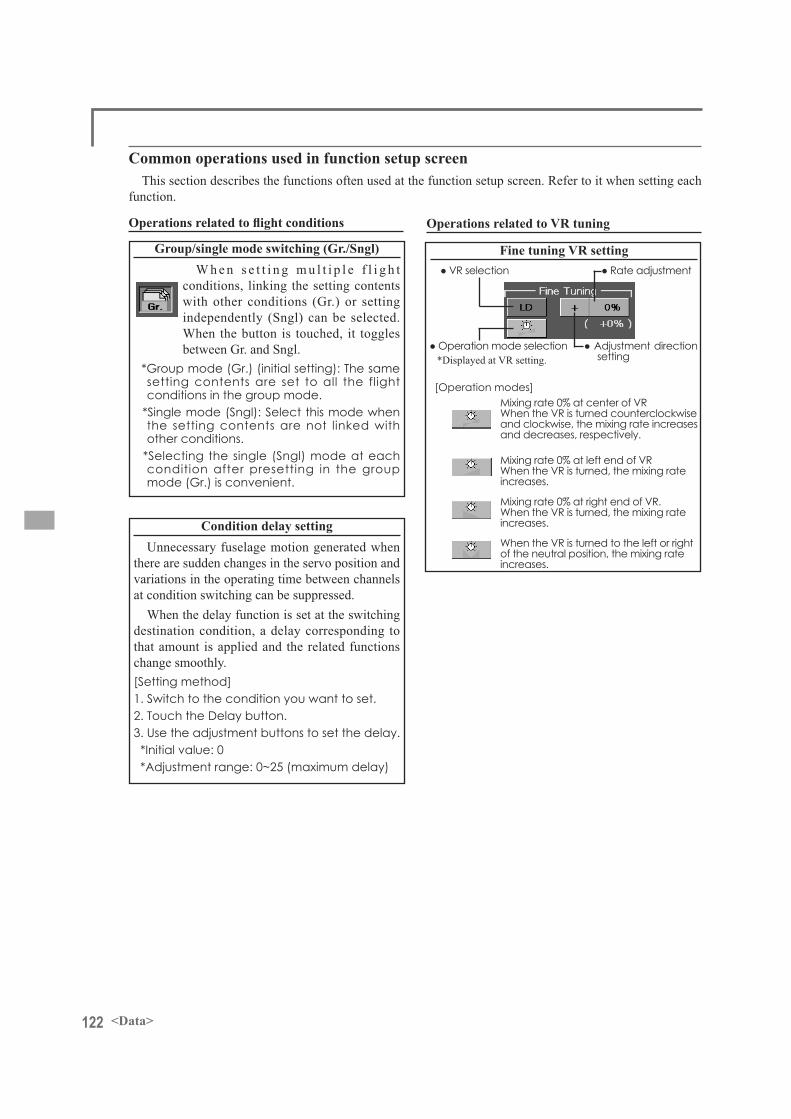
122 <Data>
Fine tuning VR setting
Mixing rate 0% at center of VRWhen the VR is turned counterclockwise and clockwise, the mixing rate increases and decreases, respectively.
Mixing rate 0% at left end of VRWhen the VR is turned, the mixing rate increases.
Mixing rate 0% at right end of VR. When the VR is turned, the mixing rate increases.
When the VR is turned to the left or right of the neutral position, the mixing rate increases.
*Displayed at VR setting. setting
Common operations used in function setup screenThis section describes the functions often used at the function setup screen. Refer to it when setting each
function.
Group/single mode switching (Gr./Sngl)W h e n s e t t i n g m u l t i p l e f l i g h t
conditions, linking the setting contents with other conditions (Gr.) or setting independently (Sngl) can be selected. When the button is touched, it toggles between Gr. and Sngl.
*Group mode (Gr.) (initial setting): The same setting contents are set to all the flight conditions in the group mode.
*Single mode (Sngl): Select this mode when the setting contents are not linked with other conditions.
*Selecting the single (Sngl) mode at each condition after presetting in the group mode (Gr.) is convenient.
Condition delay settingUnnecessary fuselage motion generated when
there are sudden changes in the servo position and variations in the operating time between channels at condition switching can be suppressed.
When the delay function is set at the switching destination condition, a delay corresponding to that amount is applied and the related functions change smoothly.
1. Switch to the condition you want to set.2. Touch the Delay button.
*Initial value: 0
Operations related to VR tuning
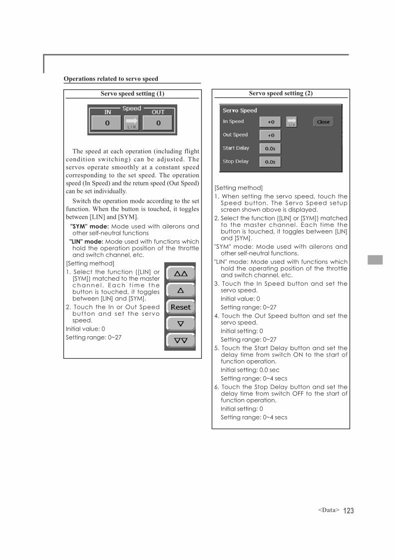
123<Data>
Servo speed setting (1)
The speed at each operation (including flight condition switching) can be adjusted. The servos operate smoothly at a constant speed corresponding to the set speed. The operation speed (In Speed) and the return speed (Out Speed) can be set individually.
Switch the operation mode according to the set function. When the button is touched, it toggles between [LIN] and [SYM]. "SYM" mode: Mode used with ailerons and
other self-neutral functions "LIN" mode: Mode used with functions which
hold the operation position of the throttle and switch channel, etc.
c h a n n e l . E a c h t i m e t h e button is touched, it toggles
button and set the servo speed.
Initial value: 0
Operations related to servo speed
Servo speed setting (2)
1. When setting the servo speed, touch the Speed button. The Servo Speed setup screen shown above is displayed.
to the master channel. Each time the
"SYM" mode: Mode used with ailerons and other self-neutral functions.
"LIN" mode: Mode used with functions which hold the operating position of the throttle and switch channel, etc.
3. Touch the In Speed button and set the servo speed.Initial value: 0
servo speed.Initial setting: 0
function operation.Initial setting: 0.0 sec
6. Touch the Stop Delay button and set the
function operation.Initial setting: 0

124 <Data>
Curve setting operationThis section describes the setting procedure of curves which are used with the AFR function and each
mixing function.
Curve type selectionWhen the curve type select button on the mixing function screen or other screen is touched, the setup
screen shown below is called.of original function
Curve type selection1. Touch the button of the curve type you want to use. *The curve type changes and the display returns to the original screen.
Linear curve adjustmentRate A and Rate B can be adjusted separately or
simultaneously.
* [Separate] mode:separately.
*[Combined] mode:simultaneously.
1. Select the setting mode.
*Initial value: +100.0%
The curve can also be offset horizontally in thevertical direction and the rate reference point can be offset to the left or right.
*Initial value: +0.0%
Setting by curve typeWhen the curve type is selected as described above, adjustment buttons corresponding to the curve type
appear on the original screen. Adjust each curve as described below.
move the reference point to the left or right.
*Initial value: +0.0%
(Linear curve)
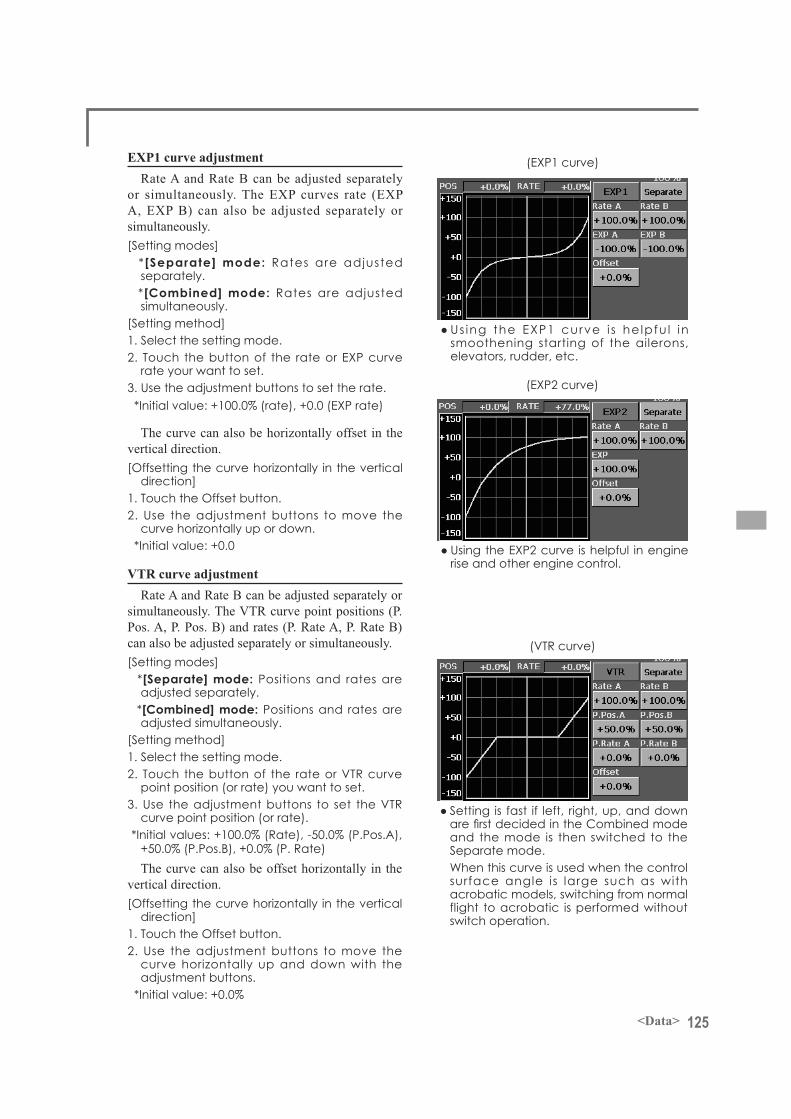
125<Data>
EXP1 curve adjustmentRate A and Rate B can be adjusted separately
or simultaneously. The EXP curves rate (EXP A, EXP B) can also be adjusted separately or simultaneously.
* [Separate] mode:separately.
*[Combined] mode:simultaneously.
1. Select the setting mode.2. Touch the button of the rate or EXP curve
rate your want to set.
*Initial value: +100.0% (rate), +0.0 (EXP rate)
The curve can also be horizontally offset in the vertical direction.
*Initial value: +0.0
(EXP1 curve)
smoothening starting of the ailerons, elevators, rudder, etc.
(EXP2 curve)
rise and other engine control.VTR curve adjustment
Rate A and Rate B can be adjusted separately or simultaneously. The VTR curve point positions (P. Pos. A, P. Pos. B) and rates (P. Rate A, P. Rate B) can also be adjusted separately or simultaneously.
*[Separate] mode: Positions and rates are
*[Combined] mode: Positions and rates are
1. Select the setting mode.2. Touch the button of the rate or VTR curve
point position (or rate) you want to set.
curve point position (or rate).
The curve can also be offset horizontally in the vertical direction.
*Initial value: +0.0%
(VTR curve)
and the mode is then switched to the Separate mode.When this curve is used when the control surface angle is large such as with acrobatic models, switching from normal flight to acrobatic is performed without switch operation.

126 <Data>
Line and spline curve adjustmentLine curves or spline curves of up to 17 points
can be used. (Initial value: 9 points) The set points can be freely increased, decreased, and offset. Curves which are symmetrical to the left and right of center can also be set.
*[Separate] mode: Normal setting *[Combined] mode:
symmetrical curve.
the selected point.)2. Touch the Rate button.
rate.[Point addition method]
stick, etc. to the point you want to add and
appears on the graph.)
outlined point appears on the graph.)
3. Touch the Rate button.
[Point deletion]
is the selected point.)
point becomes an outlined point.)
*The point is deleted.
The curve can also be offset horizontally in the vertical direction.
*Initial value: +0.0%
(Line curve)
(Spline curve)
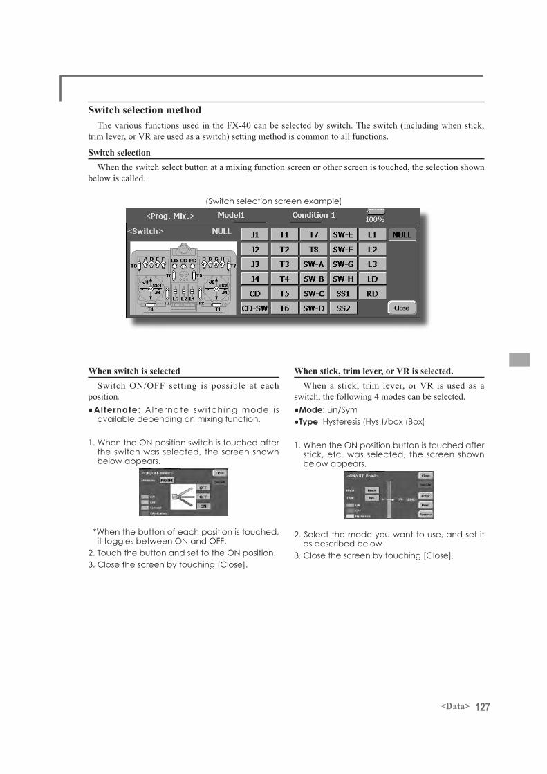
127<Data>
Switch selection methodThe various functions used in the FX-40 can be selected by switch. The switch (including when stick,
trim lever, or VR are used as a switch) setting method is common to all functions.
Switch selectionWhen the switch select button at a mixing function screen or other screen is touched, the selection shown
below is called.
(Switch selection screen example)
When switch is selectedSwitch ON/OFF setting is possible at each
position.Alternate:available depending on mixing function.
the switch was selected, the screen shownbelow appears.
*When the button of each position is touched,
When stick, trim lever, or VR is selected.When a stick, trim lever, or VR is used as a
switch, the following 4 modes can be selected.Mode: Lin/SymType:
stick, etc. was selected, the screen shownbelow appears.
2. Select the mode you want to use, and set it as described below.
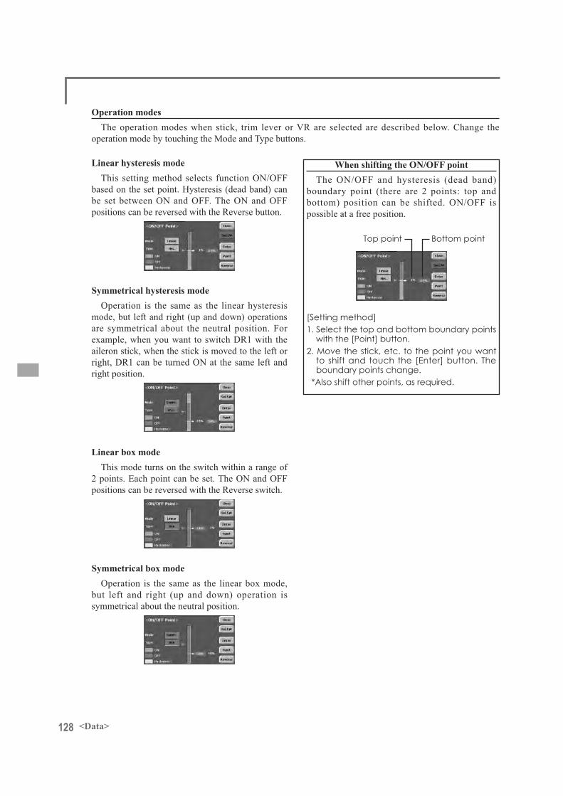
128 <Data>
Operation modesThe operation modes when stick, trim lever or VR are selected are described below. Change the
operation mode by touching the Mode and Type buttons.
Linear hysteresis modeThis setting method selects function ON/OFF
based on the set point. Hysteresis (dead band) can be set between ON and OFF. The ON and OFF positions can be reversed with the Reverse button.
Symmetrical hysteresis modeOperation is the same as the linear hysteresis
mode, but left and right (up and down) operations are symmetrical about the neutral position. For example, when you want to switch DR1 with the aileron stick, when the stick is moved to the left or right, DR1 can be turned ON at the same left and right position.
Linear box modeThis mode turns on the switch within a range of
2 points. Each point can be set. The ON and OFF positions can be reversed with the Reverse switch.
Symmetrical box modeOperation is the same as the linear box mode,
but left and right (up and down) operation is symmetrical about the neutral position.
When shifting the ON/OFF pointThe ON/OFF and hysteresis (dead band)
boundary point (there are 2 points: top and bottom) position can be shifted. ON/OFF is possible at a free position.
1. Select the top and bottom boundary points
2. Move the stick, etc. to the point you want
boundary points change.
Top point

129<Data>
Updating
update the program.
Updating procedureNote: If the battery fully discharges during
program updating, updating will fail. When
less, always recharge the battery before updating.
Note: The model data in the transmitter will not be changed after updating, but to be safe, back up the model data before updating.
Normal operation mode
Update modeUpdate switch
Card slot
into the card slot.
(update switch) at the side of the card slot in the up direction.
seconds later, the screen shown below will appear. To abort updating, turn off the transmitter power.
appear. Turn off the power to the transmitter
4. When the rotary switch is pushed, updating starts. During updating, the bar graph moves to the right.
shown below appears.
LED goes off, switch the update switch in the down direction.
completed, turn on the power and then check the system program version at the system menu information screen.


![FUT. REVISO ROAD - Caledon · 2021. 1. 13. · fut. reviso road 82.40m @ 0.50% fut. reviso road fut. lotus flower road fut. nonni avenue [261.58] [261.51] [261.62] [261.74] [261.95]](https://static.fdocuments.us/doc/165x107/61496760080bfa626014968c/fut-reviso-road-caledon-2021-1-13-fut-reviso-road-8240m-050-fut-reviso.jpg)