FX-30P OPERATION MANUALdl.mitsubishielectric.com/dl/fa/document/manual/plc_fx/jy997d34401/... ·...
182
OPERATION MANUAL FX-30P
Transcript of FX-30P OPERATION MANUALdl.mitsubishielectric.com/dl/fa/document/manual/plc_fx/jy997d34401/... ·...
OPERATION MANUAL
FX-30P

Before installation, operation, maintenance or inspection of this product, thoroughly read through andunderstand this manual and all of the associated manuals. Also, take care to handle the module properly andsafely.
This manual classifies the safety precautions into two categories: and .
Depending on the circumstances, procedures indicated by may also cause severe injury. It is important to follow all precautions for personal safety. Store this manual in a safe place so that it can be taken out and read whenever necessary. Always forward itto the end user.
1. OPERATION PRECAUTIONS
2. DESIGN PRECAUTIONS
Indicates that incorrect handling may cause hazardous conditions, resulting in death or severeinjury.
Indicates that incorrect handling may cause hazardous conditions, resulting in medium or slightpersonal injury or physical damage.
Reference
• Thoroughly read the manual and sufficiently assure safety before executing the operation to forcibly set devices toON/OFF or the operation to change present values and set values of word devices in the test mode.Otherwise, the machine may be damaged and accidents may occur by erroneous operations.
57
Reference
• When executing control (data changes) to an operating PLC, construct an interlock circuit in the sequence programso that the entire system operates conservatively.Additionally, when executing control such as program changes and operation status changes (status control) to anoperating PLC, thoroughly read the manual and sufficiently confirm safety in advance.
• Make sure to have the following safety circuits outside the PLC to ensure safe system operation even duringexternal power supply problems or PLC failure.Otherwise, malfunctions may cause serious accidents.1) Most importantly, have the following: an emergency stop circuit, a protection circuit, an interlock circuit for
opposite movements (such as normal vs. reverse rotation), and an interlock circuit (to prevent damage to theequipment at the upper and lower positioning limits).
2) Note that when the PLC CPU detects an error, such as a watchdog timer error, during self-diagnosis, all outputsare turned off. Also, when an error that cannot be detected by the PLC CPU occurs in an input/output controlblock, output control may be disabled.External circuits and mechanisms should be designed to ensure safe machinery operation in such case.
28
Reference
• Observe the following items. Failure to do so may cause incorrect data-writing through noise to the PLC and resultin PLC failure, machine damage or other accidents.1) Do not bundle the control line together with or lay it close to the main circuit or power line. As a guideline, lay the
control line at least 100mm (3.94") or more away from the main circuit or power line.Noise may cause malfunctions.
2) Ground the shield wire or shield of a shielded cable. Do not use common grounding with heavy electricalsystems.
• Install module so that excessive force will not be applied to the power connector.Failure to do so may result in wire damage/breakage or PLC failure.
28
Safety Precautions(Read these precautions before use.)
(1)
Safety Precautions(Read these precautions before use.)
3. INSTALLATION PRECAUTIONS
4. STARTUP AND MAINTENANCE PRECAUTIONS
5. DISPOSAL PRECAUTIONS
6. TRANSPORTATION AND STORAGE PRECAUTIONS
Reference
• Use the product within the generic environment specifications described in Section 2.1 of this manual.Never use the product in areas with excessive dust, oily smoke, conductive dusts, corrosive gas (salt air, Cl2, H2S,SO2, or NO2), flammable gas, vibration or impacts, or expose it to high temperature, condensation, or rain andwind.If the product is used in such conditions, electric shock, fire, malfunctions, deterioration or damage may occur.
• Do not touch the conductive parts of the product directly.Doing so may cause device failures or malfunctions.
• Connect cables securely to their designated connectors.Loose connections may cause malfunctions.
• Do not connect a PLC and a personal computer at the same time to the FX-30P.Failure to do so may cause equipment failures or malfunctions.
23
Reference
• Turn off the power to the PLC before attaching or detaching the battery.Doing so may cause equipment failures, or malfunctions.
• Use the battery for memory backup correctly in conformance to this manual.- Use the battery only for the specified purpose.- Connect the battery correctly.- Do not charge, disassemble, heat, put in fire, short-circuit, connect reversely, weld, swallow or burn the battery,
or apply excessive forces (vibration, impact, drop, etc.) to the battery.- Do not store or use the battery at high temperatures or expose to direct sunlight.- Do not expose to water, bring near fire or touch liquid leakage or other contents directly.- Incorrect handling of the battery may cause heat excessive generation, bursting, ignition, liquid leakage or
deformation, and lead to injury, fire or failures and malfunctions of facilities and other equipment.• Before modifying or disrupting the program in operation or running the PLC, carefully read through this manual and
the associated manuals and ensure the safety of the operation.An operation error may damage the machinery or cause accidents.
• Do not change the program in the PLC from two or more peripheral equipment devices at the same time. (i.e. froma programming tool and a GOT)Doing so may cause destruction or malfunction of the PLC program.
23140
Reference
• Do not disassemble or modify the PLC. Doing so may cause fire, equipment failures, or malfunctions. For repair,contact your local Mitsubishi Electric representative.
• Turn off the power to the PLC before connecting or disconnecting cable.Failure to do so may cause equipment failures or malfunctions.
23
Reference
• Please contact a certified electronic waste disposal company for the environmentally safe recycling and disposal ofyour device. When disposing of batteries, separate them from other waste according to local regulations.(For details of the Battery Directive in EU countries, refer to Appendix G)
20
Reference
• The FX-30P is a precision instrument. During transportation, avoid impacts larger than those specified in thegeneral specifications (refer to Section 2.1) of this manual. Failure to do so may cause failures in the FX-30P.After transportation, verify the operations of the FX-30P.
• Before transporting the FX-30P, make sure to turn on the power of the FX-30P, and confirm that an HPP low batteryvoltage error does not occur (or confirm that the HPP battery voltage is 2.7 V or more).If the FX-30P is transported when the battery voltage is low and the battery life is expired, the battery-backed datamay not be held correctly during transportation.
• When transporting lithium batteries, follow required transportation regulations.(For details of the regulated products, refer to Appendix F)
20140
(2)
FX-30P Operation Manual
FX-30P
Operation Manual
Foreword
This manual contains text, diagrams and explanations which will guide the reader in the correct installation and operation of the FX-30P. It should be read and understood before attempting to install or use the unit.Store this manual in a safe place so that you can take it out and read it whenever necessary. Always forward it to the end user.
© 2008 MITSUBISHI ELECTRIC CORPORATION
Manual number JY997D34401
Manual revision G
Date 4/2015
This manual confers no industrial property rights or any rights of any other kind, nor does it confer any patent licenses. MitsubishiElectric Corporation cannot be held responsible for any problems involving industrial property rights which may occur as a result ofusing the contents noted in this manual.
1
FX-30P Operation Manual
Outline Precautions
• This manual provides information for the use of the FX-30P HANDY PROGRAMMING PANEL. The manual has been written to be used by trained and competent personnel. The definition of such a person or persons is as follows;
1) Any engineer who is responsible for the planning, design and construction of automatic equipment usingthe product associated with this manual should be of a competent nature, trained and qualified to thelocal and national standards required to fulfill that role. These engineers should be fully aware of allaspects of safety with aspects regarding to automated equipment.
2) Any commissioning or maintenance engineer must be of a competent nature, trained and qualified to thelocal and national standards required to fulfill the job. These engineers should also be trained in the useand maintenance of the completed product. This includes being familiar with all associated manuals anddocumentation for the product. All maintenance should be carried out in accordance with establishedsafety practices.
3) All operators of the completed equipment should be trained to use that product in a safe and coordinatedmanner in compliance with established safety practices. The operators should also be familiar withdocumentation that is connected with the actual operation of the completed equipment.
Note: The term 'completed equipment' refers to a third party constructed device that contains or uses the product associated with this manual.
• This product has been manufactured as a general-purpose part for general industries, and has not been designed or manufactured to be incorporated in a device or system used in purposes related to human life.
• Before using the product for special purposes such as nuclear power, electric power, aerospace, medicine or passenger movement vehicles, consult with Mitsubishi Electric.
• This product has been manufactured under strict quality control. However when installing the product where major accidents or losses could occur if the product fails, install appropriate backup or failsafe functions into the system.
• When combining this product with other products, please confirm the standards and codes of regulation to which the user should follow. Moreover, please confirm the compatibility of this product with the system, machines, and apparatuses to be used.
• If there is doubt at any stage during installation of the product, always consult a professional electrical engineer who is qualified and trained in the local and national standards. If there is doubt about the operation or use, please consult the nearest Mitsubishi Electric representative.
• Since the examples within this manual, technical bulletin, catalog, etc. are used as reference; please use it after confirming the function and safety of the equipment and system. Mitsubishi Electric will not accept responsibility for actual use of the product based on these illustrative examples.
• The content, specification etc. of this manual may be changed for improvement without notice.• The information in this manual has been carefully checked and is believed to be accurate; however, if you
notice any doubtful point, error, etc., please contact the nearest Mitsubishi Electric representative.
Registration
• Ethernet is a trademark of Xerox Corporation.
• MODBUS is a registered trademark of Schneider Electric SA.• The company name and the product name to be described in this manual are the registered trademarks or
trademarks of each company.
2
FX-30P Operation Manual Table of Contents
Table of ContentsSAFETY PRECAUTIONS .................................................................................................. (1)Standards................................................................................................................................... 7
Certification of UL, cUL standards ....................................................................................................... 7 Compliance with EC directive (CE Marking) ........................................................................................ 7
Associated Manuals.................................................................................................................. 9Generic Names/Abbreviations/Explanation of key operations Used in the Manual ......... 12Reading the Manual ................................................................................................................ 15
1. Introduction 16
1.1 Outline........................................................................................................................................... 161.2 Major Features of the FX-30P....................................................................................................... 161.3 External Dimensions and Part Names .......................................................................................... 161.4 Key Layout .................................................................................................................................... 171.5 Function List.................................................................................................................................. 18
2. Specifications, Product configuration 20
2.1 General specifications................................................................................................................... 202.2 Power supply specification............................................................................................................ 202.3 Performance specification............................................................................................................. 212.4 Communication specification ........................................................................................................ 21
2.4.1 Communication specification......................................................................................................... 212.4.2 Communication speed................................................................................................................... 21
2.5 Configuration................................................................................................................................. 222.5.1 Product configuration..................................................................................................................... 222.5.2 System configuration ..................................................................................................................... 222.5.3 Applicable PLC.............................................................................................................................. 22
3. Connection Method/Startup Procedure 23
3.1 Connection to the PLC.................................................................................................................. 243.2 Connection to a personal computer .............................................................................................. 253.3 Startup procedure ......................................................................................................................... 25
4. Outline of Programming 28
4.1 Menu Structure.............................................................................................................................. 294.2 Common programming items........................................................................................................ 30
4.2.1 Programming screen ..................................................................................................................... 304.2.2 Key input........................................................................................................................................ 314.2.3 HELP screen ................................................................................................................................. 35
4.3 Functions used in programming.................................................................................................... 364.4 Types of program memories ......................................................................................................... 36
3
FX-30P Operation Manual Table of Contents
5. Online Mode 37
5.1 Overview of online mode............................................................................................................... 375.2 Read.............................................................................................................................................. 37
5.2.1 Overview of the read operation ..................................................................................................... 375.2.2 Read by step No............................................................................................................................ 375.2.3 Read by instruction........................................................................................................................ 385.2.4 Read by pointer ............................................................................................................................. 385.2.5 Read by device.............................................................................................................................. 39
5.3 Write.............................................................................................................................................. 395.3.1 Overview of the write operation ..................................................................................................... 395.3.2 Input of basic instructions.............................................................................................................. 405.3.3 Writing of application instructions .................................................................................................. 415.3.4 Input of labels (P, I) ....................................................................................................................... 435.3.5 Input of numbers............................................................................................................................ 445.3.6 Batch write of NOP to specified range (Program clear to specified range) ................................... 455.3.7 Batch write of NOP to specify the entire range (Program all clear) ............................................... 455.3.8 Modification method (before/after confirmation) ............................................................................ 465.3.9 Modification of a device ................................................................................................................. 48
5.4 Insert ............................................................................................................................................. 495.4.1 Overview of the insert operation.................................................................................................... 495.4.2 Insert operation.............................................................................................................................. 50
5.5 Delete............................................................................................................................................ 515.5.1 Overview of the delete operation................................................................................................... 515.5.2 Deletion of instructions and pointers ............................................................................................. 525.5.3 Batch deletion of a program by specifying the range to be deleted............................................... 535.5.4 Batch deletion of NOP instructions................................................................................................ 53
5.6 Monitor .......................................................................................................................................... 545.6.1 Overview of the monitor operation................................................................................................. 545.6.2 List program monitor...................................................................................................................... 555.6.3 Device monitor............................................................................................................................... 555.6.4 Operation state monitor ................................................................................................................. 56
5.7 Test ............................................................................................................................................... 575.7.1 Overview of the test function ......................................................................................................... 575.7.2 Forcible setting of devices to ON/OFF .......................................................................................... 585.7.3 Change the present value of word devices (T, C, D, V, Z, R) ....................................................... 595.7.4 Change the set value of timers (T) and counters (C) .................................................................... 60
5.8 Others Function............................................................................................................................. 625.8.1 Overview of the others function ..................................................................................................... 625.8.2 Change to offline ........................................................................................................................... 635.8.3 Diagnostics PLC............................................................................................................................ 645.8.4 Memory cassette transfer .............................................................................................................. 665.8.5 Parameter...................................................................................................................................... 715.8.6 Keyword......................................................................................................................................... 835.8.7 Device conversion ......................................................................................................................... 975.8.8 Latch clear ..................................................................................................................................... 985.8.9 Device batch monitoring .............................................................................................................. 1005.8.10 BFM batch monitor .................................................................................................................... 1045.8.11 Baud rate ................................................................................................................................... 1055.8.12 Clear PLC memory .................................................................................................................... 1065.8.13 Remote RUN/STOP .................................................................................................................. 1085.8.14 Set PLC clock ............................................................................................................................ 109
4

FX-30P Operation Manual Table of Contents
6. Offline mode 110
6.1 Outline of offline mode ................................................................................................................ 1106.2 Others Functions......................................................................................................................... 111
6.2.1 Outline of others function............................................................................................................. 1116.2.2 Change to online ......................................................................................................................... 1126.2.3 Program check ............................................................................................................................ 1136.2.4 HPP-FX Transfer ......................................................................................................................... 1156.2.5 HPP-PC Transfer......................................................................................................................... 1226.2.6 PLC Type..................................................................................................................................... 1246.2.7 HPP Memory clear ...................................................................................................................... 1286.2.8 Program manager........................................................................................................................ 129
7. HPP setting 135
7.1 Menu display language selection ................................................................................................ 1357.2 Buzzer sound volume setting ...................................................................................................... 1357.3 LCD contrast adjustment............................................................................................................. 1367.4 Backlight brightness adjustment ................................................................................................. 1367.5 Screen save ................................................................................................................................ 1367.6 HPP protection ............................................................................................................................ 1377.7 HPP initialization ......................................................................................................................... 1387.8 HPP F/W update ......................................................................................................................... 139
8. Battery 140
8.1 Battery Handling.......................................................................................................................... 1408.2 Battery specifications, Battery life ............................................................................................... 140
8.2.1 Differences between FX-30P’s internal battery and the optional battery..................................... 1408.2.2 Battery life and replacement guidelines....................................................................................... 141
8.3 Reading the date of manufacture................................................................................................ 1428.4 Battery Replacement................................................................................................................... 143
Appendix A: ASCII Code 145
Appendix A-1 ASCII Code Table .............................................................................................. 145Appendix A-2 Examples of ASCII codes .................................................................................. 145
Appendix B: Message List 146
Appendix B-1 Error messages list ............................................................................................ 146Appendix B-2 Error messages displayed during PLC diagnostic/program check..................... 148
Appendix B-2-1 For FX3S/FX3G/FX3GC/FX3U/FX3UC PLCs ............................................................... 148Appendix B-2-2 For FX1S/FX1N/FX1NC/FX2N/FX2NC PLCs................................................................ 156Appendix B-2-3 For FX2(FX)/FX2C/FX0/FX0S/FX0N PLCs.................................................................. 161
Appendix C: Major Key Operation List 164
5
FX-30P Operation Manual Table of Contents
Appendix D: Manufacturer's serial number/Version Information 166
Appendix D-1 Version check method ....................................................................................... 166Appendix D-2 Version Information............................................................................................ 167
Appendix D-2-1 Checking the firmware version ................................................................................... 167Appendix D-2-2 Version upgrade history.............................................................................................. 167
Appendix E: Discontinued models 169
Appendix F: Precautions for Battery Transportation 171
Appendix F-1 Regulated FX-30P.............................................................................................. 171Appendix F-2 Transport guidelines........................................................................................... 171
Appendix G: Handling of Batteries and Devices with Built-in Batteries in EU Member States 173
Appendix G-1 Disposal precautions ......................................................................................... 173Appendix G-2 Exportation precautions ..................................................................................... 173Appendix G-3 Regulated FX-30P ............................................................................................. 173
Warranty................................................................................................................................. 175Revised History ..................................................................................................................... 176
6

StandardsFX-30P Operation Manual
Standards
Certification of UL, cUL standards
FX-30P units comply with the UL standards (UL, cUL).
UL, cUL File number :E95239
Regarding the standards that comply with the main unit, please refer to either the FX series product catalog orconsult with your nearest Mitsubishi product provider.
Compliance with EC directive (CE Marking)
This note does not guarantee that an entire mechanical module produced in accordance with the contents ofthis note will comply with the following standards.Compliance to EMC directive and LVD directive for the entire mechanical module should be checked by theuser / manufacturer. For more information please consult with your nearest Mitsubishi product provider.Regarding the standards that comply with the main unit, please refer to either the FX series product catalog orconsult with your nearest Mitsubishi product provider.
Requirement for Compliance with EMC directive
The following products have shown compliance through direct testing (of the identified standards below) and design analysis (through the creation of a technical construction file) to the European Directive for Electromagnetic Compatibility (2004/108/EC) when used as directed by the appropriate documentation.
Attention
• This product is designed for use in industrial applications.
Note
• Authorized Representative in the European Community:Mitsubishi Electric Europe B.V.Gothaer Str. 8, 40880 Ratingen, Germany
Type: Programmable Controller (Open Type Equipment)Models: MELSEC FX series manufactured from December 1st, 2008 FX-30P
Standard Remark
EN61131-2:2007Programmable controllers
- Equipment requirements and tests
Compliance with all relevant aspects of the standard.EMI
• Radiated Emission• Conducted Emission
EMS• Radiated electromagnetic field• Fast transient burst• Electrostatic discharge• High-energy surge• Voltage drops and interruptions• Conducted RF• Power frequency magnetic field
7

StandardsFX-30P Operation Manual
Caution for EC Directive
Attach the ferrite core to the communication cables (PLC side).Attach the ferrite core in approximately 100mm(3.93") or less from connector on the PLC side.For the ferrite core use the following product or one with equivalent specifications.Model name: ZCAT2035-0930 (Manufactured by TDK co., Ltd.)
FX-30P100mm(3.93")or less
Ferrite core
Communicationcable
FX Series PLC
8

Associated ManualsFX-30P Operation Manual
Associated Manuals
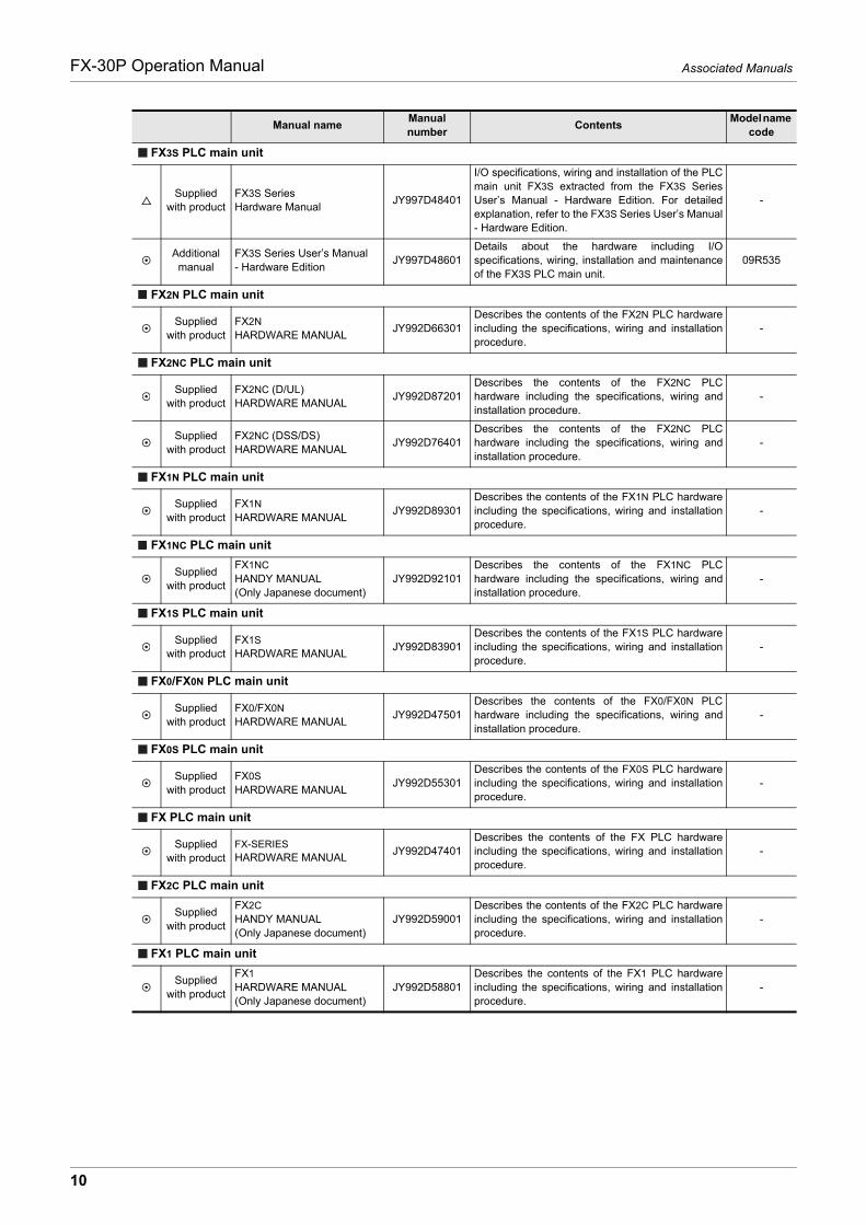
Only the installation manual is packed together with the FX-30P.For a detailed explanation of the FX-30P, refer to this manual.For the hardware information and instructions of PLC main units, refer to the respective manuals.For acquiring manuals, contact the representative you purchased the product from.
Essential manual Manual required depending on application Manual with additional manual for detailed explanation
Manual nameManual number
ContentsModel name
code
Manuals for PLC main unit
FX3U PLC main unit
Supplied with product
FX3U Series Hardware Manual
JY997D18801
I/O specifications, wiring and installation of the PLCmain unit FX3U extracted from the FX3U SeriesUser’s Manual - Hardware Edition. For detailedexplanation, refer to the FX3U Series User’sManual - Hardware Edition.
-
Additional manual
FX3U Series User’s Manual -Hardware Edition
JY997D16501Details about the hardware including I/Ospecifications, wiring, installation and maintenanceof the FX3U PLC main unit.
09R516
FX3UC PLC main unit
Supplied with product
FX3UC(D, DS, DSS)Series Hardware Manual
JY997D28601
I/O specifications, wiring and installation of the PLCmain unit FX3UC(D, DS, DSS) extracted from theFX3UC Series User’s Manual - Hardware Edition.For detailed explanation, refer to the FX3UC SeriesUser’s Manual - Hardware Edition.
-
Supplied with product
FX3UC-32MT-LT-2Hardware Manual
JY997D31601
I/O specifications, wiring and installation of the PLCmain unit FX3UC-32MT-LT-2 extracted from theFX3UC Series User’s Manual - Hardware Edition.For detailed explanation, refer to the FX3UC SeriesUser’s Manual - Hardware Edition.
-
Supplied with product
FX3UC-32MT-LTHardware Manual(Only Japanese document)
JY997D12701
I/O specifications, wiring and installation of the PLCmain unit FX3UC-32MT-LT extracted from theFX3UC Series User’s Manual - Hardware Edition.For detailed explanation, refer to the FX3UC SeriesUser’s Manual - Hardware Edition.
-
Additional manual
FX3UC Series User’s Manual- Hardware Edition
JY997D28701Details about the hardware including I/O specifications, wiring, installation and maintenance of the FX3UC PLC main unit.
09R519
FX3G PLC main unit
Supplied with product
FX3G SeriesHardware Manual
JY997D46001
I/O specifications, wiring and installation of the PLCmain unit FX3G extracted from the FX3G SeriesUser’s Manual - Hardware Edition. For detailedexplanation, refer to the FX3G Series User’sManual - Hardware Edition.
-
Additional manual
FX3G Series User’s Manual- Hardware Edition
JY997D31301Details about the hardware including I/Ospecifications, wiring, installation and maintenanceof the FX3G PLC main unit.
09R521
FX3GC PLC main unit
Supplied with product
FX3GC SeriesHardware Manual
JY997D45201
I/O specifications, wiring and installation of the PLCmain unit FX3GC extracted from the FX3GC SeriesUser’s Manual - Hardware Edition. For detailedexplanation, refer to the FX3GC Series User’sManual - Hardware Edition.
-
Additional manual
FX3GC Series User’s Manual - Hardware Edition
JY997D45401Details about the hardware including I/Ospecifications, wiring, installation and maintenanceof the FX3GC PLC main unit.
09R533
9
Associated ManualsFX-30P Operation Manual
FX3S PLC main unit
Supplied with product
FX3S SeriesHardware Manual
JY997D48401
I/O specifications, wiring and installation of the PLCmain unit FX3S extracted from the FX3S SeriesUser’s Manual - Hardware Edition. For detailedexplanation, refer to the FX3S Series User’s Manual- Hardware Edition.
-
Additional manual
FX3S Series User’s Manual- Hardware Edition
JY997D48601Details about the hardware including I/Ospecifications, wiring, installation and maintenanceof the FX3S PLC main unit.
09R535
FX2N PLC main unit
Supplied with product
FX2NHARDWARE MANUAL
JY992D66301Describes the contents of the FX2N PLC hardwareincluding the specifications, wiring and installationprocedure.
-
FX2NC PLC main unit
Supplied with product
FX2NC (D/UL) HARDWARE MANUAL
JY992D87201Describes the contents of the FX2NC PLChardware including the specifications, wiring andinstallation procedure.
-
Supplied with product
FX2NC (DSS/DS) HARDWARE MANUAL
JY992D76401Describes the contents of the FX2NC PLChardware including the specifications, wiring andinstallation procedure.
-
FX1N PLC main unit
Supplied with product
FX1NHARDWARE MANUAL
JY992D89301Describes the contents of the FX1N PLC hardwareincluding the specifications, wiring and installationprocedure.
-
FX1NC PLC main unit
Supplied with product
FX1NCHANDY MANUAL(Only Japanese document)
JY992D92101Describes the contents of the FX1NC PLChardware including the specifications, wiring andinstallation procedure.
-
FX1S PLC main unit
Supplied with product
FX1SHARDWARE MANUAL
JY992D83901Describes the contents of the FX1S PLC hardwareincluding the specifications, wiring and installationprocedure.
-
FX0/FX0N PLC main unit
Supplied with product
FX0/FX0NHARDWARE MANUAL
JY992D47501Describes the contents of the FX0/FX0N PLChardware including the specifications, wiring andinstallation procedure.
-
FX0S PLC main unit
Supplied with product
FX0SHARDWARE MANUAL
JY992D55301Describes the contents of the FX0S PLC hardwareincluding the specifications, wiring and installationprocedure.
-
FX PLC main unit
Supplied with product
FX-SERIESHARDWARE MANUAL
JY992D47401Describes the contents of the FX PLC hardwareincluding the specifications, wiring and installationprocedure.
-
FX2C PLC main unit
Supplied with product
FX2CHANDY MANUAL(Only Japanese document)
JY992D59001Describes the contents of the FX2C PLC hardwareincluding the specifications, wiring and installationprocedure.
-
FX1 PLC main unit
Supplied with product
FX1HARDWARE MANUAL(Only Japanese document)
JY992D58801Describes the contents of the FX1 PLC hardwareincluding the specifications, wiring and installationprocedure.
-
Manual nameManual number
ContentsModel name
code
10
Associated ManualsFX-30P Operation Manual
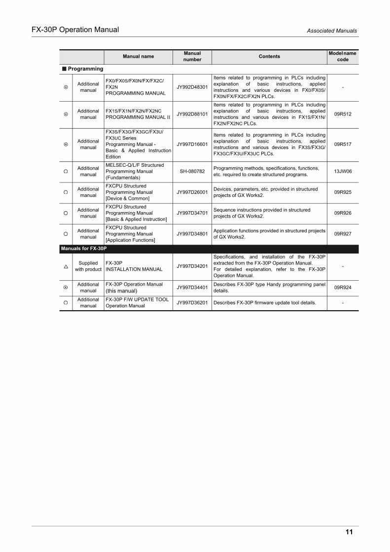
Programming
Additional manual
FX0/FX0S/FX0N/FX/FX2C/FX2NPROGRAMMING MANUAL
JY992D48301
Items related to programming in PLCs includingexplanation of basic instructions, appliedinstructions and various devices in FX0/FX0S/FX0N/FX/FX2C/FX2N PLCs.
-
Additional manual
FX1S/FX1N/FX2N/FX2NCPROGRAMMING MANUAL
JY992D88101
Items related to programming in PLCs includingexplanation of basic instructions, appliedinstructions and various devices in FX1S/FX1N/FX2N/FX2NC PLCs.
09R512
Additional manual
FX3S/FX3G/FX3GC/FX3U/FX3UC Series Programming Manual - Basic & Applied InstructionEdition
JY997D16601
Items related to programming in PLCs includingexplanation of basic instructions, appliedinstructions and various devices in FX3S/FX3G/FX3GC/FX3U/FX3UC PLCs.
09R517
Additional manual
MELSEC-Q/L/F Structured Programming Manual (Fundamentals)
SH-080782Programming methods, specifications, functions,etc. required to create structured programs.
13JW06
Additional manual
FXCPU Structured Programming Manual [Device & Common]
JY997D26001Devices, parameters, etc. provided in structuredprojects of GX Works2.
09R925
Additional manual
FXCPU Structured Programming Manual [Basic & Applied Instruction]
JY997D34701Sequence instructions provided in structured projects of GX Works2.
09R926
Additional manual
FXCPU Structured Programming Manual [Application Functions]
JY997D34801Application functions provided in structured projectsof GX Works2.
09R927
Manuals for FX-30P
Supplied with product
FX-30PINSTALLATION MANUAL
JY997D34201
Specifications, and installation of the FX-30Pextracted from the FX-30P Operation Manual.For detailed explanation, refer to the FX-30POperation Manual.
-
Additional manual
FX-30P Operation Manual (this manual)
JY997D34401Describes FX-30P type Handy programming paneldetails.
09R924
Additionalmanual
FX-30P F/W UPDATE TOOLOperation Manual
JY997D36201 Describes FX-30P firmware update tool details. -
Manual nameManual number
ContentsModel name
code
11

Generic Names/Abbreviations/Explanation of key operations Used in the ManualFX-30P Operation Manual
Generic Names/Abbreviations/Explanation of key operations Used in the Manual
Abbreviation/generic name
Name
Programmable controllers
FX3U Series Generic name of FX3U Series PLCs
FX3U PLC or main unit Generic name of FX3U Series PLC main units
FX3UC Series Generic name of FX3UC Series PLCs
FX3UC PLC or main unit Generic name of FX3UC Series PLC main units
FX3G Series Generic name of FX3G Series PLCs
FX3G PLC or main unit Generic name of FX3G Series PLC main units
FX3GC Series Generic name of FX3GC Series PLCs
FX3GC PLC or main unit Generic name of FX3GC Series PLC main units
FX3S Series Generic name of FX3S Series PLCs
FX3S PLC or main unit Generic name of FX3S Series PLC main units
FX2N Series Generic name of FX2N Series PLCs
FX2N PLC or main unit Generic name of FX2N Series PLC main units
FX2NC Series Generic name of FX2NC Series PLCs
FX2NC PLC or main unit Generic name of FX2NC Series PLC main units
FX1N Series Generic name of FX1N Series PLCs
FX1N PLC or main unit Generic name of FX1N Series PLC main units
FX1NC Series Generic name of FX1NC Series PLCs
FX1NC PLC or main unit Generic name of FX1NC Series PLC main units
FX1S Series Generic name of FX1S Series PLCs
FX1S PLC or main unit Generic name of FX1S Series PLC main units
FX0N Series Generic name of FX0N Series PLCs
FX0N PLC or main unit Generic name of FX0N Series PLC main units
FX0S Series Generic name of FX0S Series PLCs
FX0S PLC or main unit Generic name of FX0S Series PLC main units
FX0 Series Generic name of FX0 Series PLCs
FX0 PLC or main unit Generic name of FX0 Series PLC main units
FX2(FX) Series Generic name of FX2(FX) Series PLCs
FX2(FX) PLC or main unit Generic name of FX2(FX) Series PLC main units
FX2C Series Generic name of FX2C Series PLCs
FX2C PLC or main unit Generic name of FX2C Series PLC main units
FX1 Series Generic name of FX1 Series PLCs
FX1 PLC or main unit Generic name of FX1 Series PLC main units
Expansion boards
Expansion boardGeneric name of expansion boards.Connectable equipment may vary depending on the main unit. For connectable equipment, referto the manual of the main unit.
Special adapters
Special adapter
Generic name of special high speed I/O adapters, special communication adapters, and specialanalog adapters.Connectable equipment may vary depending on the main unit. For connectable equipment, referto the manual of the main unit.
12
Generic Names/Abbreviations/Explanation of key operations Used in the ManualFX-30P Operation Manual
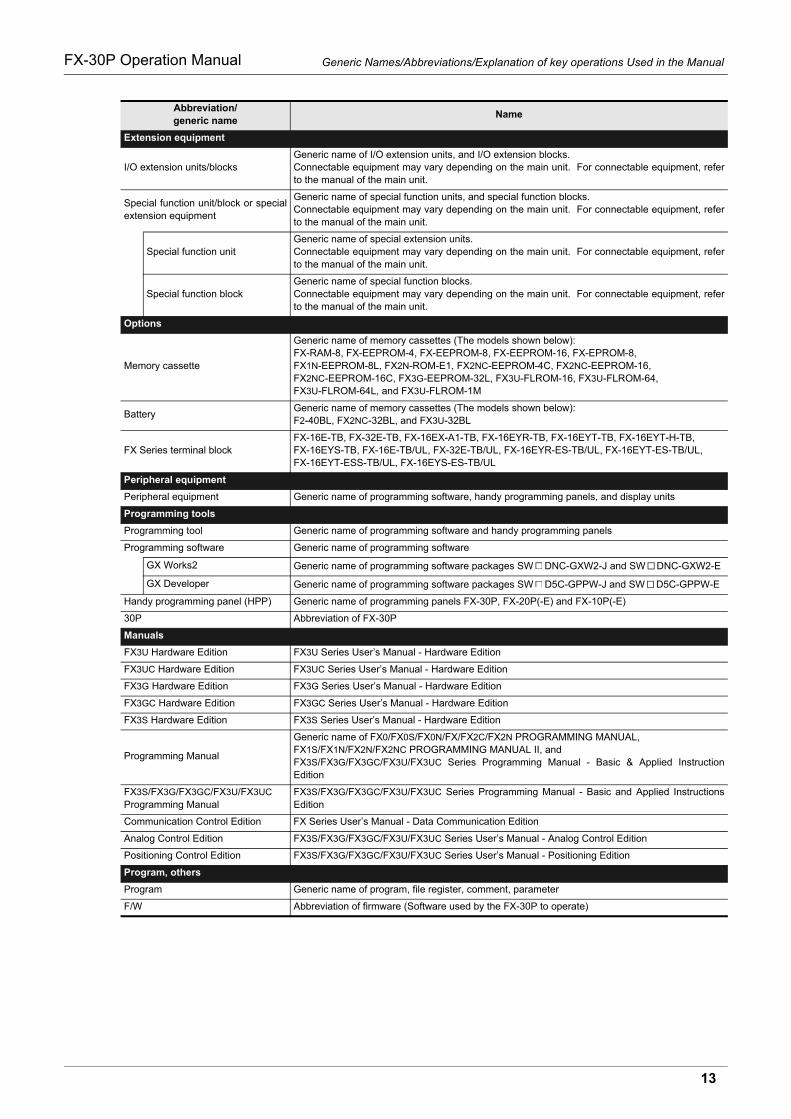
Extension equipment
I/O extension units/blocksGeneric name of I/O extension units, and I/O extension blocks.Connectable equipment may vary depending on the main unit. For connectable equipment, referto the manual of the main unit.
Special function unit/block or specialextension equipment
Generic name of special function units, and special function blocks.Connectable equipment may vary depending on the main unit. For connectable equipment, referto the manual of the main unit.
Special function unitGeneric name of special extension units.Connectable equipment may vary depending on the main unit. For connectable equipment, referto the manual of the main unit.
Special function blockGeneric name of special function blocks.Connectable equipment may vary depending on the main unit. For connectable equipment, referto the manual of the main unit.
Options
Memory cassette
Generic name of memory cassettes (The models shown below):FX-RAM-8, FX-EEPROM-4, FX-EEPROM-8, FX-EEPROM-16, FX-EPROM-8, FX1N-EEPROM-8L, FX2N-ROM-E1, FX2NC-EEPROM-4C, FX2NC-EEPROM-16, FX2NC-EEPROM-16C, FX3G-EEPROM-32L, FX3U-FLROM-16, FX3U-FLROM-64, FX3U-FLROM-64L, and FX3U-FLROM-1M
BatteryGeneric name of memory cassettes (The models shown below):F2-40BL, FX2NC-32BL, and FX3U-32BL
FX Series terminal blockFX-16E-TB, FX-32E-TB, FX-16EX-A1-TB, FX-16EYR-TB, FX-16EYT-TB, FX-16EYT-H-TB, FX-16EYS-TB, FX-16E-TB/UL, FX-32E-TB/UL, FX-16EYR-ES-TB/UL, FX-16EYT-ES-TB/UL, FX-16EYT-ESS-TB/UL, FX-16EYS-ES-TB/UL
Peripheral equipment
Peripheral equipment Generic name of programming software, handy programming panels, and display units
Programming tools
Programming tool Generic name of programming software and handy programming panels
Programming software Generic name of programming software
GX Works2 Generic name of programming software packages SW DNC-GXW2-J and SW DNC-GXW2-E
GX Developer Generic name of programming software packages SW D5C-GPPW-J and SW D5C-GPPW-E
Handy programming panel (HPP) Generic name of programming panels FX-30P, FX-20P(-E) and FX-10P(-E)
30P Abbreviation of FX-30P
Manuals
FX3U Hardware Edition FX3U Series User’s Manual - Hardware Edition
FX3UC Hardware Edition FX3UC Series User’s Manual - Hardware Edition
FX3G Hardware Edition FX3G Series User’s Manual - Hardware Edition
FX3GC Hardware Edition FX3GC Series User’s Manual - Hardware Edition
FX3S Hardware Edition FX3S Series User’s Manual - Hardware Edition
Programming Manual
Generic name of FX0/FX0S/FX0N/FX/FX2C/FX2N PROGRAMMING MANUAL, FX1S/FX1N/FX2N/FX2NC PROGRAMMING MANUAL II, and FX3S/FX3G/FX3GC/FX3U/FX3UC Series Programming Manual - Basic & Applied InstructionEdition
FX3S/FX3G/FX3GC/FX3U/FX3UC Programming Manual
FX3S/FX3G/FX3GC/FX3U/FX3UC Series Programming Manual - Basic and Applied InstructionsEdition
Communication Control Edition FX Series User’s Manual - Data Communication Edition
Analog Control Edition FX3S/FX3G/FX3GC/FX3U/FX3UC Series User’s Manual - Analog Control Edition
Positioning Control Edition FX3S/FX3G/FX3GC/FX3U/FX3UC Series User’s Manual - Positioning Edition
Program, others
Program Generic name of program, file register, comment, parameter
F/W Abbreviation of firmware (Software used by the FX-30P to operate)
Abbreviation/generic name
Name
13
Generic Names/Abbreviations/Explanation of key operations Used in the ManualFX-30P Operation Manual
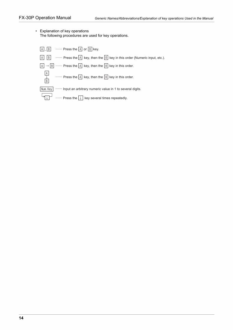
• Explanation of key operationsThe following procedures are used for key operations.
Press the key several times repeatedly.
Input an arbitrary numeric value in 1 to several digits.
Press the or key.
Press the key, then the key in this order (Numeric input, etc.).
Press the key, then the key in this order.
Press the key, then the key in this order.
14

Reading the ManualFX-30P Operation Manual
Reading the Manual
In this manual, the following formats are used for describing common items.
The above is different from the actual page, as it is provided for explanation purposes only.
5 Online Mode
5.1 Overview of online mode
33
FX-30P Operation Manual
1
Introduction
2
Specifications,product configuration
3
Connections,
startup procedure
4
Outline of
programm
ing
5
Online m
ode
6
Offline m
ode
7
HP
P setting
8
Battery
A
AS
CII C
ode
B
Message List
5. Online Mode
5.1 Overview of online mode
In the online mode, the 30P directly accessesthe program memory in the PLC.Refer to Chapter 7 for the HPP setting.
1) In the PLC, data is written to the built-inRAM when a memory cassette is notattached to the PLC, or to a memorycassette when it is attached to the PLC.Data cannot be wri t ten to a memorycassette if it is EPROM or if it is EEPROMor FLROM and the write protect switch isON. Data cannot be written either while thePLC is in the RUN status.
2) By operation from the 30P, programs can be transferred between the built in PLC memory and a memorycassette attached to the PLC.
5.2 Read
Press the key once to select the read mode, and press it again to select the write mode. (The mode isselected alternately.)
5.2.1 Overview of the read operation
When the online mode is selected, programs written to the memory of the PLC (or the memory cassette ifattached) are displayed in the 30P. When the offline mode is selected, programs written in the built in HPPRAM itself are displayed in the 30P.
• Read operation condition
5.2.2 Read by step No.
• Eight lines of the program are read and displayed from an instruction at the specified step No.
• If the specified step No. corresponds to an operand such as a set value of a timer or counter, eight lines are read and displayed from the instruction of the operand.
• Press the key again to scroll the screen display to the next line of the displayed instruction.
• Use the cursor control keys to scroll lines one by one.
Basic operation
PLC status PLC memory
RUN STOP Built in memory RAM cassetteEEPROM cassetteFLROM cassette
EPROM cassette
Transfer
30P
Programming
PLC
Write
Write
Read
This area shows the title of the chapter and the title of the section for the current page.
The right side of each page indexes the chapter number for the page currently opened.
This area shows the manual title for the current page.
Indexes the chapter number.Shows the title of the chapter and the title
of the section.
Shows the manual title.
15

1 Introduction
1.1 OutlineFX-30P Operation Manual
1. Introduction
1.1 Outline
The handy programming panel FX-30P is a compact, portable program monitor. Connect the FX-30P to aMELSEC-FX Series PLC, and use it for writing programs (sequence programs and parameters), as well asmonitoring and testing devices.
1.2 Major Features of the FX-30P
• The FX-30P is a compact, portable program monitor.
• The liquid crystal display unit with 21 characters 8 lines displays the program, PLC operation status (monitoring), operation guidance and error messages.
• The FX-30P offers both online mode and offline mode.The FX-30P directly accesses the memory of the connected PLC in the online mode, and accesses the built-in RAM in the offline mode.
• The FX-30P has a built-in battery to store programs written in the offline mode (which are stored in the RAM in the FX-30P) for approximately 5 years (Ambient temperature 25 C(77 F)).
• The FX-30P has a built-in flash memory to save up to 15 programs. The program management function can read out programs saved in the flash memory to the built-in RAM, write programs from the built-in RAM to the flash memory, and delete programs.
• The FX-30P reads/writes programs and provides a monitor display in list format.
1.3 External Dimensions and Part Names
Unit: mm (inches)MASS (Weight): 0.3kg (0.66lbs)
[1] LCD display (With backlight) [6] Battery cover
[2] PLC communication port [7] Screw for battery cover anchoring
[3] USB cover [8] FX3U-32BL type battery (standard accessory)
[4] USB communication port [9] Key
[5] Slide hook
87(3.43") 30(1.19") [6]
[2][1] [5][4][3]
[9]
[8] [7]
170(
6.7"
)
16

1 Introduction
1.4 Key LayoutFX-30P Operation Manual
1
Introduction
2
Specifications,product configuration
3
Connections,
startup procedure
4
Outline of
programm
ing
5
Online m
ode
6
Offline m
ode
7
HP
P setting
8
Battery
A
AS
CII C
ode
B
Message List
1.4 Key Layout
Each key provided on the FX-30P panel surface functions as follows:
(1)
Function keys(read/write,insert/delete, monitor/testand others/help)
Each key operates alternately. (When a key is pressed once, the function indicated in the upper part ofthe key is selected. When the key is pressed again, the function indicated in the lower part is selected.)
(2)Instruction keys,device symbol keysand numeric keys
Instructions are provided in the upper part of each key, and numbers/device numbers are provided in thelower part of each key.The function is automatically changed over between the one indicated in the upper part and the otherindicated in the lower part in accordance with operator’s actions.Among symbols indicated in the lower part, each symbol is selected alternately for "Z/V", "K/H", "T/R" and"P/I". (Every time a key is pressed, either symbol is selected alternately.)
(3) Clear keyUse this key to cancel the key input before pressing the [GO] key(before confirmation), clear an errormessage, or return to the previous screen.
(4) Device symbol keyThis key is provided to aid device symbol input. Use this key to directly specify a buffer memory or specifya device bit.
(5) Space key Use this key to enter a space in the entry column, specify a device or specify a constant.
(6) Step key Use this key to specify the step number.
(7) Cursor control keysUse these keys to move the line cursor and prompt, specify a device before or after the currentlyspecified device, or scroll lines.
(8) GO key Use this key to confirm a command, execute a command, or scroll pages.
(1)
(2)
(3)
(4)
(5)
(6)
(7)
(8)
17

1 Introduction
1.5 Function ListFX-30P Operation Manual
1.5 Function List
1) Online mode
Functions Description Reference
Programming
ReadReads (displays) sequence programs in the PLC.
Section 5.2
WriteWrites sequence programs.
(Key inputs in the 30P Program memory in the PLC)Section 5.3
InsertInserts instructions into sequence programs.
(Key inputs in the 30P Program memory in the PLC)Section 5.4
DeleteDeletes instructions from sequence programs.
(Key inputs in the 30P Program memory in the PLC)Section 5.5
MonitorReads (displays) the operation status in the PLC.
Section 5.6
TestWrites devices forcibly.
(Key inputs in the 30P Memory in the PLC)Section 5.7
Other
CHANGE TO OFFLINE Switches the mode to offline.Subsection
5.8.2
DIAGNOSTICS PLC Executes PLC diagnosis.Subsection
5.8.3
DATA TRANSFER Transfers data from the memory cassette.Subsection
5.8.4
PARAMETER Sets parameters.Subsection
5.8.5
KEYWORD Sets the keyword.Subsection
5.8.6
DEVICE CONVERSION Converts devices.Subsection
5.8.7
LATCH CLEAR Clears the latch status.Subsection
5.8.8
DEV. BATCH MONITOR Executes batch monitoring of devices.Subsection
5.8.9
BFM BATCH MONITOR Executes batch monitoring of buffer memories.Subsection
5.8.10
BAUDRATE Changes the baud rate.Subsection
5.8.11
CLEAR PLC MEMORY Clears the memory inside the PLC.Subsection
5.8.12
REMOTE RUN/STOP Switches the PLC mode between RUN and STOP.Subsection
5.8.13
SET PLC CLOCK Sets the clock in the PLC.Subsection
5.8.14
HPP SETTING Changes the setup of the HPP. Chapter 7
18

1 Introduction
1.5 Function ListFX-30P Operation Manual
1
Introduction
2
Specifications,product configuration
3
Connections,
startup procedure
4
Outline of
programm
ing
5
Online m
ode
6
Offline m
ode
7
HP
P setting
8
Battery
A
AS
CII C
ode
B
Message List
2) Offline mode
*1. For firmware versions that support the HPP-PC TRANSFER function, refer to Subsection 6.2.5.Only available for FX3S/FX3G/FX3GC/FX3U/FX3UC PLC.
3) HPP setting
Functions Description Reference
Programming
ReadReads (displays) sequence programs in 30P.
Section 5.2
WriteWrites sequence programs.
(Key inputs in the 30P Built in 30P RAM)Section 5.3
InsertInserts instructions into sequence programs.
(Key inputs in the 30P Built in 30P RAM) Section 5.4
DeleteDeletes instructions from sequence programs.
(Key inputs in the 30P Built in 30P RAM)Section 5.5
Other
CHANGE TO ONLINE Switches the mode to online.Subsection
6.2.2
PROGRAM CHECK Executes program check.Subsection
6.2.3
HPP-FX TRANSFER Transfers data between the RAM in the FX-30P and the FX PLC.Subsection
6.2.4
HPP-PC TRANSFER*1 Transfers data between the RAM in the FX-30P and the personalcomputer.
Subsection 6.2.5
PARAMETER Sets parameters.Subsection
5.8.5
DEVICE CONVERSION Converts devices.Subsection
5.8.7
CHANGE PLC TYPE Changes the PLC type.Subsection
6.2.6
HPP MEMORY CLEAR Clears the memory inside the 30P.Subsection
6.2.7
PROGRAM MANAGERManages programs stored in the RAM and flash memory (15blocks) in the FX-30P.
Subsection 6.2.8
HPP SETTING Changes the setup of the HPP. Chapter 7
Functions Description Reference
LANGUAGESelects the display language among English, Japanese, andChinese.
Section 7.1
BUZZER LEVEL Adjusts the buzzer sound volume. Section 7.2
DISPLAY CONTRAST Adjusts the LCD display contrast. Section 7.3
DISPLAY BRIGHTNESS Adjusts the brightness of the LCD display backlight. Section 7.4
SCREEN SAVE Sets the screen saver. Section 7.5
HPP PROTECT Sets protection for programs stored in the FX-30P. Section 7.6
HPP INITIALIZE Returns the FX-30P to the factory default status. Section 7.7
HPP F/W UPDATE Updates the firmware of the FX-30P. Section 7.8
19
2 Specifications, Product configuration
2.1 General specificationsFX-30P Operation Manual
2. Specifications, Product configuration
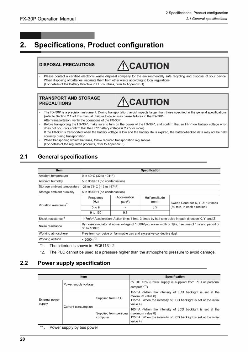
2.1 General specifications
*1. The criterion is shown in IEC61131-2.
*2. The PLC cannot be used at a pressure higher than the atmospheric pressure to avoid damage.
2.2 Power supply specification
*1. Power supply by bus power
DISPOSAL PRECAUTIONS
• Please contact a certified electronic waste disposal company for the environmentally safe recycling and disposal of your device.When disposing of batteries, separate them from other waste according to local regulations.(For details of the Battery Directive in EU countries, refer to Appendix G)
TRANSPORT AND STORAGE PRECAUTIONS
• The FX-30P is a precision instrument. During transportation, avoid impacts larger than those specified in the general specifications(refer to Section 2.1) of this manual. Failure to do so may cause failures in the FX-30P.After transportation, verify the operations of the FX-30P.
• Before transporting the FX-30P, make sure to turn on the power of the FX-30P, and confirm that an HPP low battery voltage errordoes not occur (or confirm that the HPP battery voltage is 2.7 V or more).If the FX-30P is transported when the battery voltage is low and the battery life is expired, the battery-backed data may not be heldcorrectly during transportation.
• When transporting lithium batteries, follow required transportation regulations.(For details of the regulated products, refer to Appendix F)
Item Specification
Ambient temperature 0 to 40 C (32 to 104 F)
Ambient humidity 5 to 95%RH (no condensation)
Storage ambient temperature -25 to 75 C (-13 to 167 F)
Storage ambient humidity 5 to 95%RH (no condensation)
Vibration resistance*1
Frequency(Hz)
Acceleration
(m/s2)
Half amplitude(mm) Sweep Count for X, Y, Z: 10 times
(80 min. in each direction)5 to 9 - 3.5
9 to 150 9.8 -
Shock resistance*1 147m/s2 Acceleration, Action time: 11ms, 3 times by half-sine pulse in each direction X, Y, and Z
Noise resistanceBy noise simulator at noise voltage of 1,000Vp-p, noise width of 1 s, rise time of 1ns and period of30 to 100Hz
Working atmosphere Free from corrosive or flammable gas and excessive conductive dust
Working altitude < 2000m*2
Item Specification
External powersupply
Power supply voltage5V DC 5% (Power supply is supplied from PLC or personal
computer.*1)
Current consumption
Supplied from PLC
155mA (When the intensity of LCD backlight is set at themaximum value 8)115mA (When the intensity of LCD backlight is set at the initialvalue 4)
Supplied from personalcomputer
165mA (When the intensity of LCD backlight is set at themaximum value 8)125mA (When the intensity of LCD backlight is set at the initialvalue 4)
20
2 Specifications, Product configuration
2.3 Performance specificationFX-30P Operation Manual
1
Introduction
2
Specifications,product configuration
3
Connections,
startup procedure
4
Outline of
programm
ing
5
Online m
ode
6
Offline m
ode
7
HP
P setting
8
Battery
A
AS
CII C
ode
B
Message List
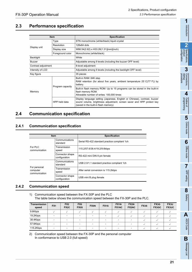
2.3 Performance specification
2.4 Communication specification
2.4.1 Communication specification
2.4.2 Communication speed
1) Communication speed between the FX-30P and the PLCThe table below shows the communication speed between the FX-30P and the PLC.
2) Communication speed between the FX-30P and the personal computerIn conformance to USB 2.0 (full speed)
Item Specification
Display unit
Type STN monochrome (white/black) liquid crystal
Resolution 128x64 dots
Display size W66.54(2.62) x H33.26(1.31)[mm](inch)
Foreground color Monochrome (white/black)
Backlight White
Buzzer Adjustable among 9 levels (including the buzzer OFF level)
Contrast adjustment 8-level adjustment
Intensity of LCD Adjustable among 9 levels (including the backlight OFF level)
Key figure 35 pieces
Memory
Program capacity
Built-in RAM: 64K step RAM retention (for about five years, ambient temperature 25 C(77 F)) bybattery.
Built-in flash memory ROM: Up to 15 programs can be stored in the built-inflash memory ROM.Allowable number of writes: 100,000 times
HPP held dataDisplay language setting (Japanese, English or Chinese), contrast, buzzersound volume, brightness adjustment, screen saver and HPP protect key(saved in the built-in flash memory)
Item Specification
For PLC communication
Communicationsstandard
Serial RS-422 standard practice compliant 1ch
Transmissionspeed
115.2/57.6/38.4/19.2/9.6kbps
Connector shape configuration
RS-422 mini DIN 8 pin female
For personal computer communication
Communicationsstandard
USB 2.0/1.1 standard practice compliant 1ch
Transmissionspeed
After serial conversion is 115.2kbps
Connector shape configuration
USB mini B plug female
Transmission speed
FX1FX2
FX2CFX0
FX0SFX0N FX1S
FX1NFX1NC
FX2NFX2NC
FX3SFX3G
FX3GCFX3U
FX3UC
9.6Kbps
19.2Kbps - - - - -
38.4Kbps - - - - - - -
57.6Kbps - - - - - - -
115.2Kbps - - - - - - -
21
2 Specifications, Product configuration
2.5 ConfigurationFX-30P Operation Manual
2.5 Configuration
2.5.1 Product configuration
1) Incorporated items list
2) Associated product list
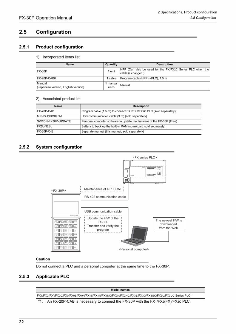
2.5.2 System configuration
Caution
Do not connect a PLC and a personal computer at the same time to the FX-30P.
2.5.3 Applicable PLC
*1. An FX-20P-CAB is necessary to connect the FX-30P with the FX1/FX2(FX)/FX2C PLC.
Name Quantity Description
FX-30P 1 unitHPP (Can also be used for the FX/FX2C Series PLC when thecable is changed.)
FX-20P-CAB0 1 cable Program cable (HPP PLC), 1.5 m
Manual(Japanese version, English version)
1 manual each
Manual
Name Description
FX-20P-CAB Program cable (1.5 m) to connect FX1/FX2/FX2C PLC (sold separately)
MR-J3USBCBL3M USB communication cable (3 m) (sold separately)
SW1DN-FX30P-UPDATE Personal computer software to update the firmware of the FX-30P (Free)
FX3U-32BL Battery to back up the built-in RAM (spare part, sold separately)
FX-30P-O-E Separate manual (this manual, sold separately)
Model names
FX1/FX2(FX)/FX2C/FX0/FX0S/FX0N/FX1S/FX1N/FX1NC/FX2N/FX2NC/FX3S/FX3G/FX3GC/FX3U/FX3UC Series PLC*1
<FX-30P>
<FX series PLC>
<Personal computer>
RS-422 communication cable
USB communication cable
Maintenance of a PLC etc.
The newest F/W isdownloaded
from the Web.
Update the F/W of the FX-30P
Transfer and verify the program
22
3 Connection Method/Startup Procedure
FX-30P Operation Manual
1
Introduction
2
Specifications,product configuration
3
Connections,
startup procedure
4
Outline of
programm
ing
5
Online m
ode
6
Offline m
ode
7
HP
P setting
8
Battery
A
AS
CII C
ode
B
Message List
3. Connection Method/Startup Procedure
INSTALLATION PRECAUTIONS
• Use the product within the generic environment specifications described in Section 2.1 of this manual.Never use the product in areas with excessive dust, oily smoke, conductive dusts, corrosive gas (salt air, Cl2, H2S, SO2, or NO2),flammable gas, vibration or impacts, or expose it to high temperature, condensation, or rain and wind.If the product is used in such conditions, electric shock, fire, malfunctions, deterioration or damage may occur.
• Do not touch the conductive parts of the product directly.Doing so may cause device failures or malfunctions.
• Connect cables securely to their designated connectors.Loose connections may cause malfunctions.
• Do not connect a PLC and a personal computer at the same time to the FX-30P.Failure to do so may cause equipment failures or malfunctions.
STARTUP AND MAINTENANCE PRECAUTIONS
• Turn off the power to the PLC before attaching or detaching the battery.Doing so may cause equipment failures, or malfunctions.
• Use the battery for memory backup correctly in conformance to this manual.- Use the battery only for the specified purpose.- Connect the battery correctly.- Do not charge, disassemble, heat, put in fire, short-circuit, connect reversely, weld, swallow or burn the battery, or apply
excessive forces (vibration, impact, drop, etc.) to the battery.- Do not store or use the battery at high temperatures or expose to direct sunlight.- Do not expose to water, bring near fire or touch liquid leakage or other contents directly.- Incorrect handling of the battery may cause heat excessive generation, bursting, ignition, liquid leakage or deformation, and lead
to injury, fire or failures and malfunctions of facilities and other equipment.• Before modifying or disrupting the program in operation or running the PLC, carefully read through this manual and the associated
manuals and ensure the safety of the operation.An operation error may damage the machinery or cause accidents.
• Do not change the program in the PLC from two or more peripheral equipment devices at the same time. (i.e. from a programmingtool and a GOT)Doing so may cause destruction or malfunction of the PLC program.
STARTUP AND MAINTENANCE PRECAUTIONS
• Do not disassemble or modify the PLC. Doing so may cause fire, equipment failures, or malfunctions.For repair, contact your local Mitsubishi Electric representative.
• Turn off the power to the PLC before connecting or disconnecting cable.Failure to do so may cause equipment faiures or malfunctions.
23

3 Connection Method/Startup Procedure
3.1 Connection to the PLCFX-30P Operation Manual
3.1 Connection to the PLC
1) Connection to the FX0/FX0S/FX0N/FX1S/FX1N/FX1NC/FX2N/FX2NC/FX3S/FX3G/FX3GC/FX3U/FX3UC SeriesPLC.
2) Connection to the FX1/FX2(FX)/FX2C Series PLC.
Caution
Never touch the PLC connection area of the HPP main unit. Static electricity may damage internal electricalcircuits. Turn OFF the power of the PLC before connecting the HPP to the PLC.
PLC
HPP
HPP connector
In a PLC having the HPP connectorcover, open the connector cover first, and then attach the HPP connector.(The HPP connector cover is not provided in FX1NC/FX2NC/FX3GC/ FX3U/FX3UC PLCs.)
Programming cableFX-20P-CAB0 (1.5 m)
PLC
HPP
HPP connector
Programming cableFX-20P-CAB (1.5 m)
In the case of FX2C Series PLC,connect the program cable to the HPP connection port inside the smoke cover.
24

3 Connection Method/Startup Procedure
3.2 Connection to a personal computerFX-30P Operation Manual
1
Introduction
2
Specifications,product configuration
3
Connections,
startup procedure
4
Outline of
programm
ing
5
Online m
ode
6
Offline m
ode
7
HP
P setting
8
Battery
A
AS
CII C
ode
B
Message List
3.2 Connection to a personal computer
Connect the FX-30P to the USB communication port of a personal computer using a USB communicationcable.
3.3 Startup procedure
• While the power of the PLC is OFF, connect the HPP to the PLC.
• The top screen is displayed for 2 seconds after the power is turned ON.
• The current firmware version is displayed at the bottom of the top screen.
• Turning the power of the FX-30P ON while pressing and holding the
and keys at the same time sets the FX-30P to the HPPF/W update standby status (if the manufacturer's serial number is 950000 or later).For details, refer to Section 7.8.
• If the language is not selected for the following reasons, the language selection screen appears after the top screen.
- If the power of the FX-30P is turned ON for the first time after delivery
- If the HPP is initialized
Select either language using the and keys, and then press the
key to confirm the selection.
<FX-30P>
USB communication cable(MR-J3USBCBL3M)
<Personal computer>
Connect the HPP to the PLC, power PLC ON.
Firmware version
To next page
Displayed for 2 seconds after the power is turned ON
25
3 Connection Method/Startup Procedure
3.3 Startup procedureFX-30P Operation Manual
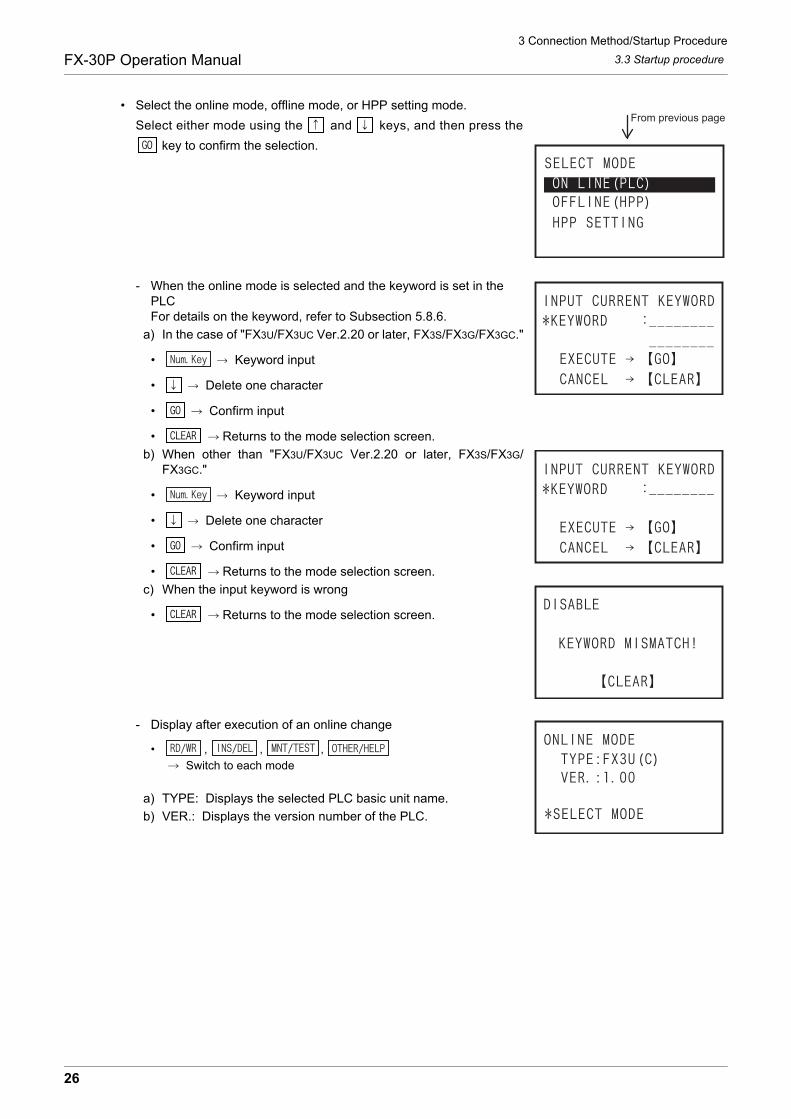
• Select the online mode, offline mode, or HPP setting mode.
Select either mode using the and keys, and then press the
key to confirm the selection.
- When the online mode is selected and the keyword is set in the PLCFor details on the keyword, refer to Subsection 5.8.6.
a) In the case of "FX3U/FX3UC Ver.2.20 or later, FX3S/FX3G/FX3GC."
• Keyword input
• Delete one character
• Confirm input
• Returns to the mode selection screen.
b) When other than "FX3U/FX3UC Ver.2.20 or later, FX3S/FX3G/FX3GC."
• Keyword input
• Delete one character
• Confirm input
• Returns to the mode selection screen.
c) When the input keyword is wrong
• Returns to the mode selection screen.
- Display after execution of an online change
• , , ,
Switch to each mode
a) TYPE: Displays the selected PLC basic unit name.
b) VER.: Displays the version number of the PLC.
From previous page
26
3 Connection Method/Startup Procedure
3.3 Startup procedureFX-30P Operation Manual
1
Introduction
2
Specifications,product configuration
3
Connections,
startup procedure
4
Outline of
programm
ing
5
Online m
ode
6
Offline m
ode
7
HP
P setting
8
Battery
A
AS
CII C
ode
B
Message List
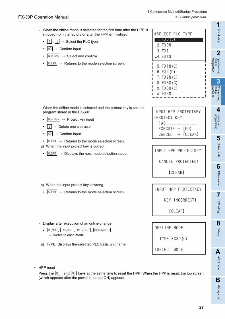
- When the offline mode is selected for the first time after the HPP is shipped from the factory or after the HPP is initialized
• , Select the PLC type.
• Confirm input
• Select and confirm
• Returns to the mode selection screen.
- When the offline mode is selected and the protect key is set in a program stored in the FX-30P
• Protect key input
• Delete one character
• Confirm input
• Returns to the mode selection screen.
a) When the input protect key is correct
• Displays the next mode selection screen.
b) When the input protect key is wrong
• Returns to the mode selection screen.
- Display after execution of an online change
• , , ,
Switch to each mode
a) TYPE: Displays the selected PLC basic unit name.
• HPP reset
Press the and keys at the same time to reset the HPP. When the HPP is reset, the top screen (which appears after the power is turned ON) appears.
27

4 Outline of Programming
FX-30P Operation Manual
4. Outline of Programming
In the FX-30P, use input keys and instruction list to create programs.The destination to write a created program is different between the online mode and the offline mode.In the online mode, a program is directly written to the program memory in the PLC. In the offline mode, aprogram is written to the built in HPP RAM. When operating the PLC with a program created in the offlinemode, the program should be transferred from the HPP to the PLC.
DESIGN PRECAUTIONS
• When executing control (data changes) to an operating PLC, construct an interlock circuit in the sequence program so that the entiresystem operates conservatively.Additionally, when executing control such as program changes and operation status changes (status control) to an operating PLC,thoroughly read the manual and sufficiently confirm safety in advance.
• Make sure to have the following safety circuits outside the PLC to ensure safe system operation even during external power supplyproblems or PLC failure.Otherwise, malfunctions may cause serious accidents.1) Most importantly, have the following: an emergency stop circuit, a protection circuit, an interlock circuit for opposite movements
(such as normal vs. reverse rotation), and an interlock circuit (to prevent damage to the equipment at the upper and lowerpositioning limits).
2) Note that when the PLC CPU detects an error, such as a watchdog timer error, during self-diagnosis, all outputs are turned off.Also, when an error that cannot be detected by the PLC CPU occurs in an input/output control block, output control may bedisabled.External circuits and mechanisms should be designed to ensure safe machinery operation in such case.
DESIGN PRECAUTIONS
• Observe the following items. Failure to do so may cause incorrect data-writing through noise to the PLC and result in PLC failure,machine damage or other accidents.1) Do not bundle the control line together with or lay it close to the main circuit or power line. As a guideline, lay the control line at
least 100mm (3.94") or more away from the main circuit or power line.Noise may cause malfunctions.
2) Ground the shield wire or shield of a shielded cable. Do not use common grounding with heavy electrical systems.• Install module so that excessive force will not be applied to the power connector.
Failure to do so may result in wire damage/breakage or PLC failure.
28
4 Outline of Programming
4.1 Menu StructureFX-30P Operation Manual
1
Introduction
2
Specifications,product configuration
3
Connections,
startup procedure
4
Outline of
programm
ing
5
Online m
ode
6
Offline m
ode
7
HP
P setting
8
Battery
A
AS
CII C
ode
B
Message List
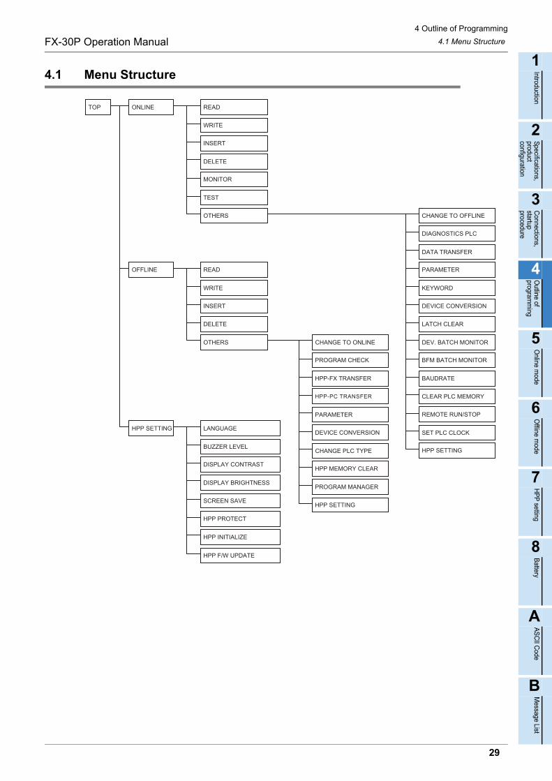
4.1 Menu Structure
29
4 Outline of Programming
4.2 Common programming itemsFX-30P Operation Manual
4.2 Common programming items
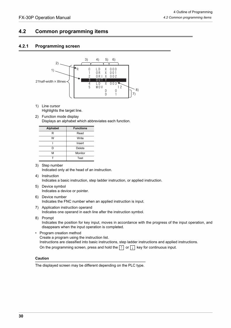
4.2.1 Programming screen
1) Line cursorHighlights the target line.
2) Function mode displayDisplays an alphabet which abbreviates each function.
3) Step numberIndicated only at the head of an instruction.
4) InstructionIndicates a basic instruction, step ladder instruction, or applied instruction.
5) Device symbolIndicates a device or pointer.
6) Device numberIndicates the FNC number when an applied instruction is input.
7) Application instruction operandIndicates one operand in each line after the instruction symbol.
8) PromptIndicates the position for key input, moves in accordance with the progress of the input operation, anddisappears when the input operation is completed.
• Program creation methodCreate a program using the instruction list.Instructions are classified into basic instructions, step ladder instructions and applied instructions.
On the programming screen, press and hold the or key for continuous input.
Caution
The displayed screen may be different depending on the PLC type.
Alphabet Functions
R Read
W Write
I Insert
D Delete
M Monitor
T Test
1)
7)8)
2)3) 4) 5) 6)
21half-width 8lines
30
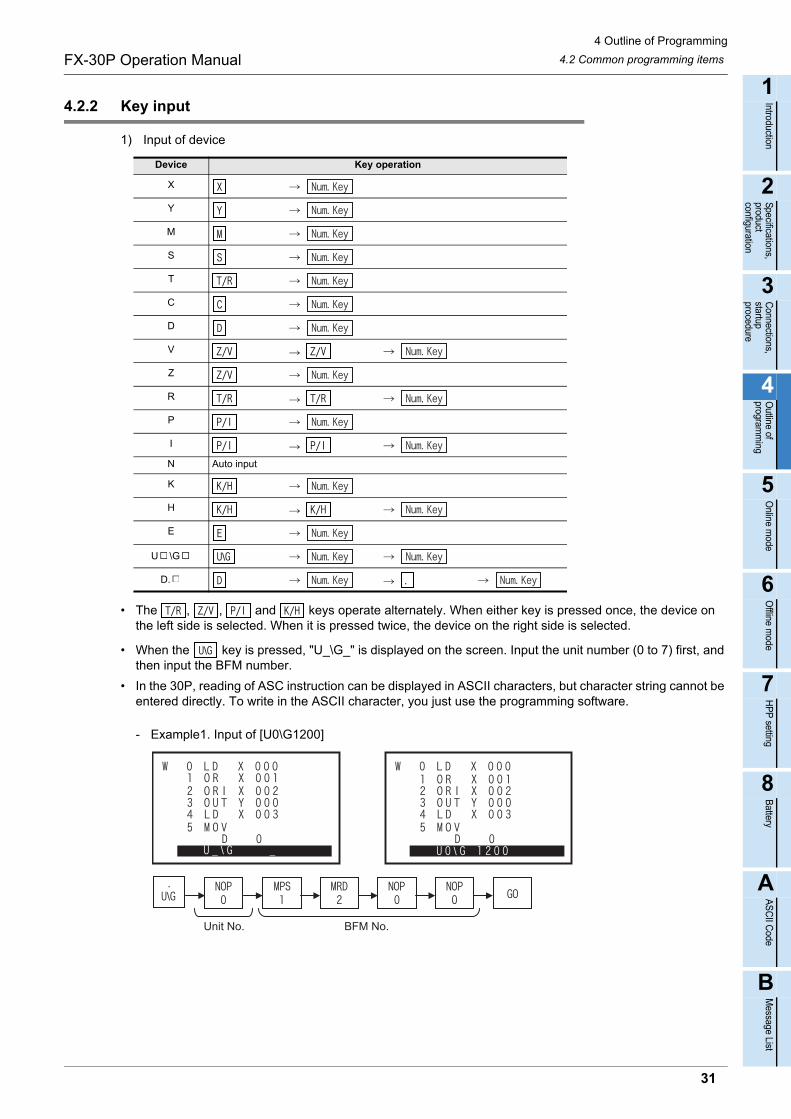
4 Outline of Programming
4.2 Common programming itemsFX-30P Operation Manual
1
Introduction
2
Specifications,product configuration
3
Connections,
startup procedure
4
Outline of
programm
ing
5
Online m
ode
6
Offline m
ode
7
HP
P setting
8
Battery
A
AS
CII C
ode
B
Message List
4.2.2 Key input
1) Input of device
• The , , and keys operate alternately. When either key is pressed once, the device on the left side is selected. When it is pressed twice, the device on the right side is selected.
• When the key is pressed, "U_\G_" is displayed on the screen. Input the unit number (0 to 7) first, and then input the BFM number.
• In the 30P, reading of ASC instruction can be displayed in ASCII characters, but character string cannot be entered directly. To write in the ASCII character, you just use the programming software.
- Example1. Input of [U0\G1200]
Device Key operation
X
Y
M
S
T
C
D
V
Z
R
P
I
N Auto input
K
H
E
U \G
D.
Unit No. BFM No.
31
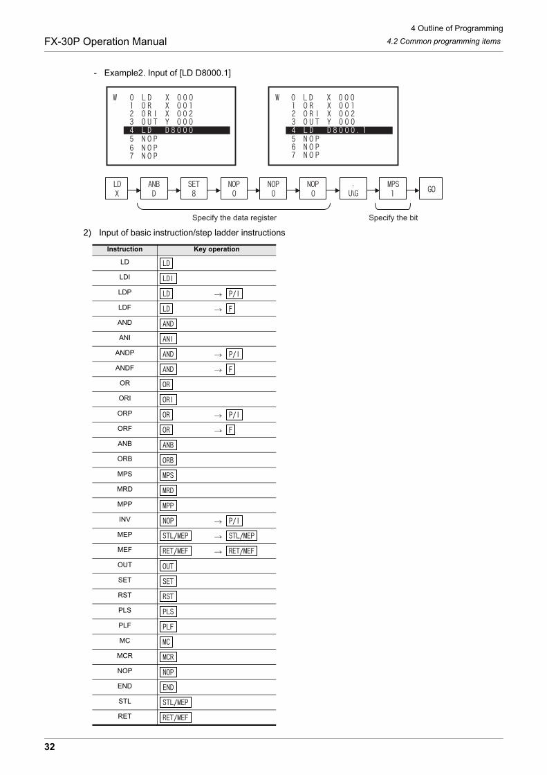
4 Outline of Programming
4.2 Common programming itemsFX-30P Operation Manual
- Example2. Input of [LD D8000.1]
2) Input of basic instruction/step ladder instructions
Instruction Key operation
LD
LDI
LDP
LDF
AND
ANI
ANDP
ANDF
OR
ORI
ORP
ORF
ANB
ORB
MPS
MRD
MPP
INV
MEP
MEF
OUT
SET
RST
PLS
PLF
MC
MCR
NOP
END
STL
RET
Specify the data register Specify the bit
32
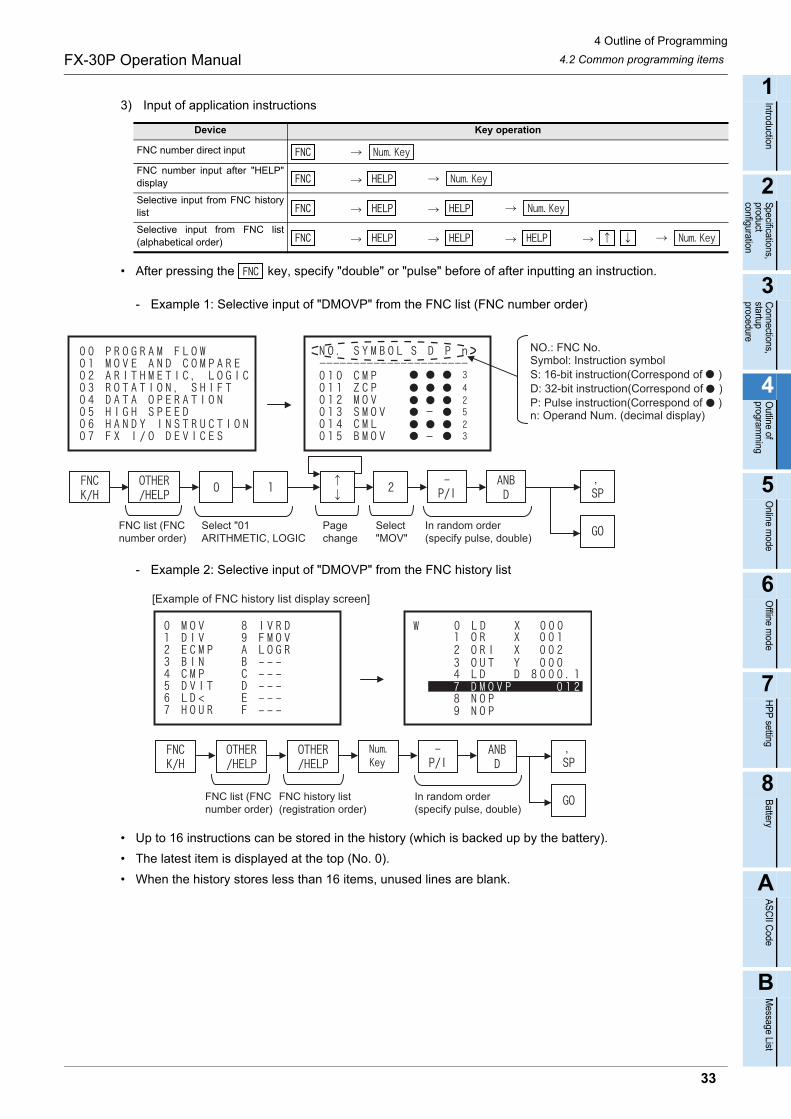
4 Outline of Programming
4.2 Common programming itemsFX-30P Operation Manual
1
Introduction
2
Specifications,product configuration
3
Connections,
startup procedure
4
Outline of
programm
ing
5
Online m
ode
6
Offline m
ode
7
HP
P setting
8
Battery
A
AS
CII C
ode
B
Message List
3) Input of application instructions
• After pressing the key, specify "double" or "pulse" before of after inputting an instruction.
- Example 1: Selective input of "DMOVP" from the FNC list (FNC number order)
- Example 2: Selective input of "DMOVP" from the FNC history list
• Up to 16 instructions can be stored in the history (which is backed up by the battery).
• The latest item is displayed at the top (No. 0).
• When the history stores less than 16 items, unused lines are blank.
Device Key operation
FNC number direct input
FNC number input after "HELP"display
Selective input from FNC historylist
Selective input from FNC list(alphabetical order)
FNC list (FNCnumber order)
Select "01ARITHMETIC, LOGIC
Pagechange
Select"MOV"
In random order(specify pulse, double)
NO.: FNC No.Symbol: Instruction symbolS: 16-bit instruction(Correspond of )D: 32-bit instruction(Correspond of )P: Pulse instruction(Correspond of )n: Operand Num. (decimal display)
[Example of FNC history list display screen]
FNC list (FNCnumber order)
FNC history list(registration order)
In random order(specify pulse, double)
33

4 Outline of Programming
4.2 Common programming itemsFX-30P Operation Manual
- Example 3: Selective input of "DMOVP" from the FNC list (alphabetical order)
• Press and hold the key to scroll the display in the sequence "Symbols A B C Z
Symbols A ". Release the key to stop scroll.
Press and hold the key to scroll the display in the sequence "Symbols Z Y X A
Symbols Z ". Release the key to stop scroll.
FNC list (FNCnumber order)
FNC list(alphabetical order)
FNC history list(registration order)
Display scrollIn random order(specify pulse, double)
34
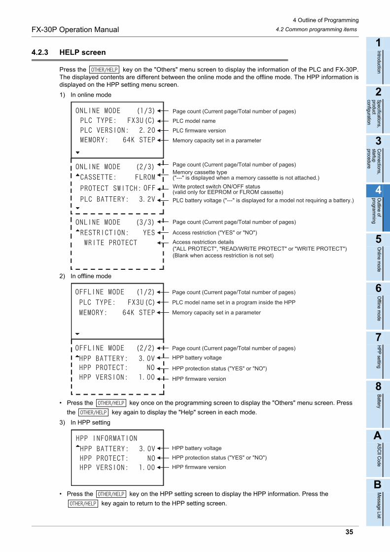
4 Outline of Programming
4.2 Common programming itemsFX-30P Operation Manual
1
Introduction
2
Specifications,product configuration
3
Connections,
startup procedure
4
Outline of
programm
ing
5
Online m
ode
6
Offline m
ode
7
HP
P setting
8
Battery
A
AS
CII C
ode
B
Message List
4.2.3 HELP screen
Press the key on the "Others" menu screen to display the information of the PLC and FX-30P.The displayed contents are different between the online mode and the offline mode. The HPP information isdisplayed on the HPP setting menu screen.
1) In online mode
2) In offline mode
• Press the key once on the programming screen to display the "Others" menu screen. Press
the key again to display the "Help" screen in each mode.
3) In HPP setting
• Press the key on the HPP setting screen to display the HPP information. Press the
key again to return to the HPP setting screen.
Page count (Current page/Total number of pages)
Access restriction ("YES" or "NO")
Access restriction details("ALL PROTECT", "READ/WRITE PROTECT" or "WRITE PROTECT")(Blank when access restriction is not set)
Page count (Current page/Total number of pages)
PLC model name
PLC firmware version
Memory capacity set in a parameter
Page count (Current page/Total number of pages)Memory cassette type("---" is displayed when a memory cassette is not attached.)
Write protect switch ON/OFF status(valid only for EEPROM or FLROM cassette)
PLC battery voltage ("---" is displayed for a model not requiring a battery.)
Page count (Current page/Total number of pages)
Page count (Current page/Total number of pages)
HPP battery voltage
HPP protection status ("YES" or "NO")
HPP firmware version
PLC model name set in a program inside the HPP
Memory capacity set in a parameter
HPP battery voltage
HPP protection status ("YES" or "NO")
HPP firmware version
35
4 Outline of Programming
4.3 Functions used in programmingFX-30P Operation Manual
4.3 Functions used in programming
4.4 Types of program memories
• RAM (Random Access Memory)Data can be read from and written to this memory as needed. The data stored in this memory should be backed up by the battery because they disappear when the power is interrupted. This memory is used also as the internal memory of the HPP and PLC. If a memory cassette is of this type, programs stored in the memory cassette disappear when the memory cassette is removed from the PLC.
• EEPROM (Electrically Erasable Programmable Read Only Memory)This memory is a kind of read only memory, but data can be written as needed by applying a specified voltage. The data stored in this memory does not disappear even if the power is interrupted. The allowable number of data writes is restricted (10,000 times for memory cassettes and memory boards, and 20,000 times for the EEPROM in PLCs). The write protect switch is provided in memory cassettes and memory boards to prevent erroneous writing.
• Flash MemoryThis memory is a kind of EEPROM. Different from conventional EEPROM, data cannot be overwritten in units of bytes. It is necessary to delete unnecessary existing data in advance in units of blocks, and then write new data.
• EPROM (Erasable Programmable Read OnlyMemory)This is a kind of read only memory. Irradiate ultraviolet rays to delete the contents stored in this memory. For writing data, clear the whole contents stored in this memory, and then write data at one time using the ROM writer. The data stored in this memory does not disappear even if the power is interrupted.
• Even if the EEPROM, EPROM, or flash memory is provided for the PLC, a dedicated battery or large-capacity capacitor is required to hold the image memory.
Functions Description Reference
ReadReads a created program from the program memory, and displays it.By specifying the step No., instruction, device, or pointer; an arbitrary position of the program can bedisplayed.
Section 5.2
Write Writes a new program or overwrites an existing program for modification or addition. Section 5.3
Insert Inserts an instruction into an existing program and carries down later step No’s. Section 5.4
DeleteDeletes a specified instruction from an existing program and carries up later step No’s.An instruction or pointer can be deleted. Batch deletion and deletion of specified ranges via the NOPinstruction is also available.
Section 5.5
36
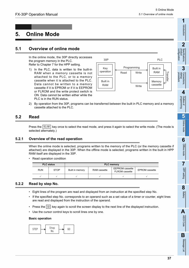
5 Online Mode
5.1 Overview of online modeFX-30P Operation Manual
1
Introduction
2
Specifications,product configuration
3
Connections,
startup procedure
4
Outline of
programm
ing
5
Online m
ode
6
Offline m
ode
7
HP
P setting
8
Battery
A
AS
CII C
ode
B
Message List
5. Online Mode
5.1 Overview of online mode
In the online mode, the 30P directly accessesthe program memory in the PLC.Refer to Chapter 7 for the HPP setting.
1) In the PLC, data is written to the built-inRAM when a memory cassette is notattached to the PLC, or to a memorycassette when it is attached to the PLC.Data cannot be wri t ten to a memorycassette if it is EPROM or if it is EEPROMor FLROM and the write protect switch isON. Data cannot be written either while thePLC is in the RUN status.
2) By operation from the 30P, programs can be transferred between the built in PLC memory and a memorycassette attached to the PLC.
5.2 Read
Press the key once to select the read mode, and press it again to select the write mode. (The mode isselected alternately.)
5.2.1 Overview of the read operation
When the online mode is selected, programs written to the memory of the PLC (or the memory cassette ifattached) are displayed in the 30P. When the offline mode is selected, programs written in the built in HPPRAM itself are displayed in the 30P.
• Read operation condition
5.2.2 Read by step No.
• Eight lines of the program are read and displayed from an instruction at the specified step No.
• If the specified step No. corresponds to an operand such as a set value of a timer or counter, eight lines are read and displayed from the instruction of the operand.
• Press the key again to scroll the screen display to the next line of the displayed instruction.
• Use the cursor control keys to scroll lines one by one.
Basic operation
PLC status PLC memory
RUN STOP Built in memory RAM cassetteEEPROM cassetteFLROM cassette
EPROM cassette
Transfer
30P
Programming
PLC
Write
Write
Read
37
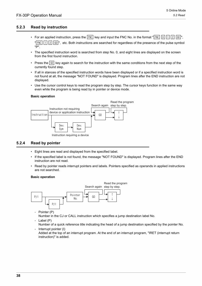
5 Online Mode
5.2 ReadFX-30P Operation Manual
5.2.3 Read by instruction
• For an applied instruction, press the key and input the FNC No. in the format " ",
" ", etc. Both instructions are searched for regardless of the presence of the pulse symbol "P".
• The specified instruction word is searched from step No. 0, and eight lines are displayed on the screen from the first found instruction.
• Press the key again to search for the instruction with the same conditions from the next step of the currently found step.
• If all in stances of the specified instruction words have been displayed or if a specified instruction word is not found at all, the message "NOT FOUND" is displayed. Program lines after the END instruction are not displayed.
• Use the cursor control keys to read the program step by step. The cursor keys function in the same way even while the program is being read by in pointer or device mode.
Basic operation
5.2.4 Read by pointer
• Eight lines are read and displayed from the specified label.
• If the specified label is not found, the message "NOT FOUND" is displayed. Program lines after the END instruction are not read.
• Read by pointer reads interrupt pointers and labels. Pointers specified as operands in applied instructions are not searched.
Basic operation
- Pointer (P)Number in the CJ or CALL instruction which specifies a jump destination label No.
- Label (P)Number of a quick reference title indicating the head of a jump destination specified by the pointer No.
- Interrupt pointer (I)Added at the top of an interrupt program. At the end of an interrupt program, "IRET (interrupt return instruction)" is added.
Instruction requiring a device
Instruction not requiringdevice or application instruction
Search againRead the programstep by step.
Search againRead the programstep by step.
38
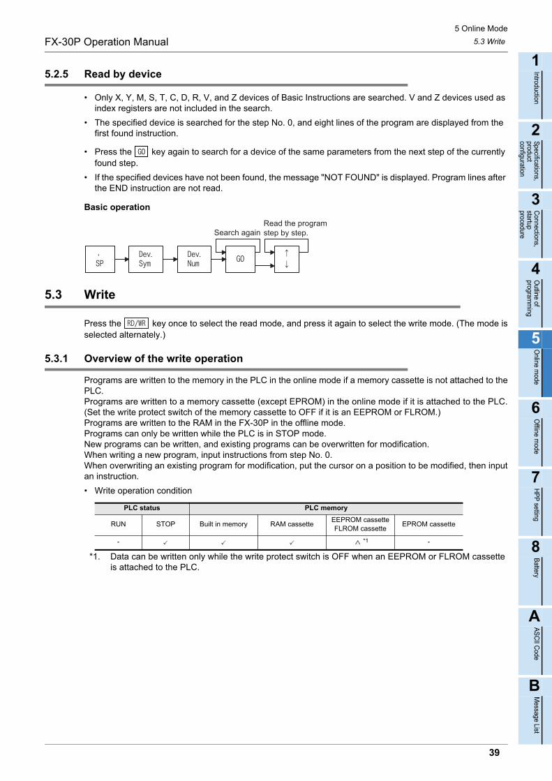
5 Online Mode
5.3 WriteFX-30P Operation Manual
1
Introduction
2
Specifications,product configuration
3
Connections,
startup procedure
4
Outline of
programm
ing
5
Online m
ode
6
Offline m
ode
7
HP
P setting
8
Battery
A
AS
CII C
ode
B
Message List
5.2.5 Read by device
• Only X, Y, M, S, T, C, D, R, V, and Z devices of Basic Instructions are searched. V and Z devices used as index registers are not included in the search.
• The specified device is searched for the step No. 0, and eight lines of the program are displayed from the first found instruction.
• Press the key again to search for a device of the same parameters from the next step of the currently found step.
• If the specified devices have not been found, the message "NOT FOUND" is displayed. Program lines after the END instruction are not read.
Basic operation
5.3 Write
Press the key once to select the read mode, and press it again to select the write mode. (The mode isselected alternately.)
5.3.1 Overview of the write operation
Programs are written to the memory in the PLC in the online mode if a memory cassette is not attached to thePLC.Programs are written to a memory cassette (except EPROM) in the online mode if it is attached to the PLC.(Set the write protect switch of the memory cassette to OFF if it is an EEPROM or FLROM.)Programs are written to the RAM in the FX-30P in the offline mode.Programs can only be written while the PLC is in STOP mode.New programs can be written, and existing programs can be overwritten for modification.When writing a new program, input instructions from step No. 0.When overwriting an existing program for modification, put the cursor on a position to be modified, then inputan instruction.
• Write operation condition
*1. Data can be written only while the write protect switch is OFF when an EEPROM or FLROM cassetteis attached to the PLC.
PLC status PLC memory
RUN STOP Built in memory RAM cassetteEEPROM cassetteFLROM cassette
EPROM cassette
- *1 -
Search againRead the programstep by step.
39
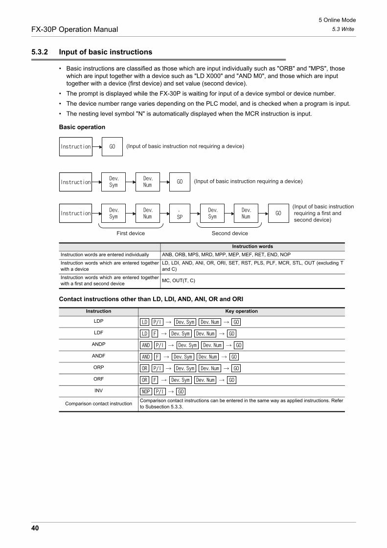
5 Online Mode
5.3 WriteFX-30P Operation Manual
5.3.2 Input of basic instructions
• Basic instructions are classified as those which are input individually such as "ORB" and "MPS", those which are input together with a device such as "LD X000" and "AND M0", and those which are input together with a device (first device) and set value (second device).
• The prompt is displayed while the FX-30P is waiting for input of a device symbol or device number.
• The device number range varies depending on the PLC model, and is checked when a program is input.
• The nesting level symbol "N" is automatically displayed when the MCR instruction is input.
Basic operation
Contact instructions other than LD, LDI, AND, ANI, OR and ORI
Instruction words
Instruction words are entered individually ANB, ORB, MPS, MRD, MPP, MEP, MEF, RET, END, NOP
Instruction words which are entered togetherwith a device
LD, LDI, AND, ANI, OR, ORI, SET, RST, PLS, PLF, MCR, STL, OUT (excluding Tand C)
Instruction words which are entered togetherwith a first and second device
MC, OUT(T, C)
Instruction Key operation
LDP
LDF
ANDP
ANDF
ORP
ORF
INV
Comparison contact instructionComparison contact instructions can be entered in the same way as applied instructions. Referto Subsection 5.3.3.
(Input of basic instruction not requiring a device)
(Input of basic instruction requiring a device)
(Input of basic instruction requiring a first and second device)
First device Second device
40
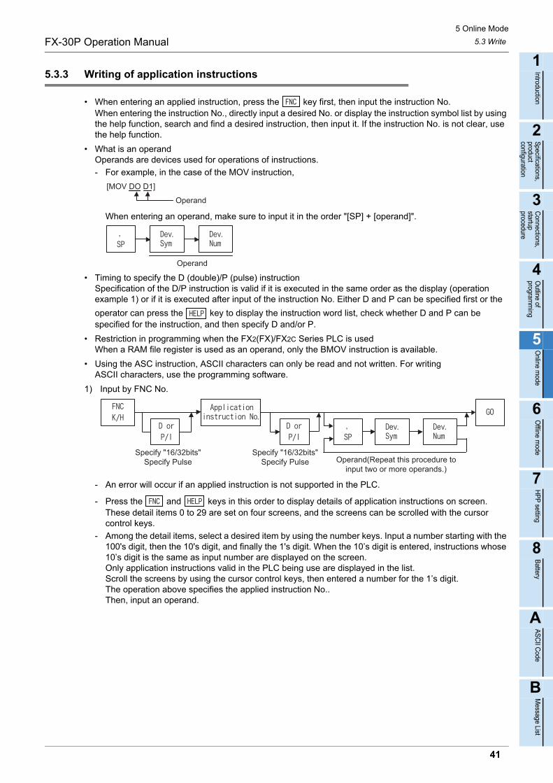
5 Online Mode
5.3 WriteFX-30P Operation Manual
1
Introduction
2
Specifications,product configuration
3
Connections,
startup procedure
4
Outline of
programm
ing
5
Online m
ode
6
Offline m
ode
7
HP
P setting
8
Battery
A
AS
CII C
ode
B
Message List
5.3.3 Writing of application instructions
• When entering an applied instruction, press the key first, then input the instruction No.When entering the instruction No., directly input a desired No. or display the instruction symbol list by using the help function, search and find a desired instruction, then input it. If the instruction No. is not clear, use the help function.
• What is an operandOperands are devices used for operations of instructions.
- For example, in the case of the MOV instruction,
When entering an operand, make sure to input it in the order "[SP] + [operand]".
• Timing to specify the D (double)/P (pulse) instructionSpecification of the D/P instruction is valid if it is executed in the same order as the display (operation example 1) or if it is executed after input of the instruction No. Either D and P can be specified first or the
operator can press the key to display the instruction word list, check whether D and P can be specified for the instruction, and then specify D and/or P.
• Restriction in programming when the FX2(FX)/FX2C Series PLC is usedWhen a RAM file register is used as an operand, only the BMOV instruction is available.
• Using the ASC instruction, ASCII characters can only be read and not written. For writingASCII characters, use the programming software.
1) Input by FNC No.
- An error will occur if an applied instruction is not supported in the PLC.
- Press the and keys in this order to display details of application instructions on screen. These detail items 0 to 29 are set on four screens, and the screens can be scrolled with the cursor control keys.
- Among the detail items, select a desired item by using the number keys. Input a number starting with the 100's digit, then the 10's digit, and finally the 1's digit. When the 10’s digit is entered, instructions whose 10’s digit is the same as input number are displayed on the screen.Only application instructions valid in the PLC being use are displayed in the list.Scroll the screens by using the cursor control keys, then entered a number for the 1’s digit.The operation above specifies the applied instruction No..Then, input an operand.
Operand
[MOV DO D1]
Operand
Operand(Repeat this procedure toinput two or more operands.)
Specify "16/32bits"Specify Pulse
Specify "16/32bits"Specify Pulse
41
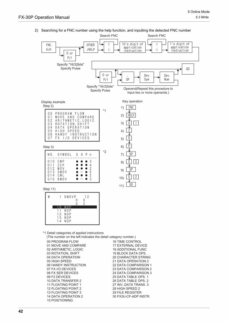
5 Online Mode
5.3 WriteFX-30P Operation Manual
2) Searching for a FNC number using the help function, and inputting the detected FNC number
Search FNC Search FNC
Operand(Repeat this procedure toinput two or more operands.)
Specify "16/32bits"Specify Pulse
Specify "16/32bits"Specify Pulse
Display example Step 2)
Step 3)
Step 11)
*1
*2
Key operation
1)
2)
3)
4)
5)
6)
7)
8)
9)
10)
11)
*1 Detail categories of applied instructions (The number on the left indicates the detail category number.)
00 PROGRAM FLOW 01 MOVE AND COMPARE 02 ARITHMETIC, LOGIC 03 ROTATION, SHIFT 04 DATA OPERATION 05 HIGH SPEED 06 HANDY INSTRUCTION 07 FX I/O DEVICES 08 FX SER DEVICES 09 F2 DEVICES 10 DATA TRANSFER 2 11 FLOATING POINT 1 12 FLOATING POINT 2 13 FLOATING POINT 3 14 DATA OPERATION 2 15 POSITIONING
16 TIME CONTROL 17 EXTERNAL DEVICE 18 ADDITIONAL FUNC 19 BLOCK DATA OPS. 20 CHARACTER STRING 21 DATA OPERATION 3 22 DATA COMPARISON 1 23 DATA COMPARISON 2 24 DATA COMPARISON 3 25 DATA TABLE OPS. 1 26 DATA TABLE OPS. 2 27 INV.,DATA TRANS. 3 28 HIGH SPEED 2 29 FILE REGISTER 30 FX3U-CF-ADP INSTR.
42
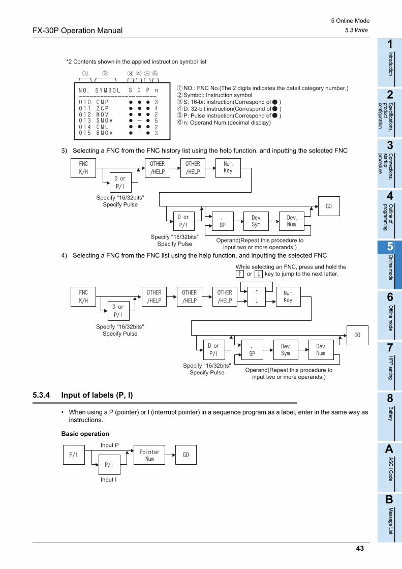
5 Online Mode
5.3 WriteFX-30P Operation Manual
1
Introduction
2
Specifications,product configuration
3
Connections,
startup procedure
4
Outline of
programm
ing
5
Online m
ode
6
Offline m
ode
7
HP
P setting
8
Battery
A
AS
CII C
ode
B
Message List
3) Selecting a FNC from the FNC history list using the help function, and inputting the selected FNC
4) Selecting a FNC from the FNC list using the help function, and inputting the selected FNC
5.3.4 Input of labels (P, I)
• When using a P (pointer) or I (interrupt pointer) in a sequence program as a label, enter in the same way as instructions.
Basic operation
NO.: FNC No.(The 2 digits indicates the detail category number.)Symbol: Instruction symbolS: 16-bit instruction(Correspond of )D: 32-bit instruction(Correspond of )P: Pulse instruction(Correspond of )n: Operand Num.(decimal display)
*2 Contents shown in the applied instruction symbol list
Specify "16/32bits"Specify Pulse
Specify "16/32bits"Specify Pulse
Operand(Repeat this procedure toinput two or more operands.)
While selecting an FNC, press and hold the or key to jump to the next letter.
Specify "16/32bits"Specify Pulse
Specify "16/32bits"Specify Pulse Operand(Repeat this procedure to
input two or more operands.)
Input P
Input I
43
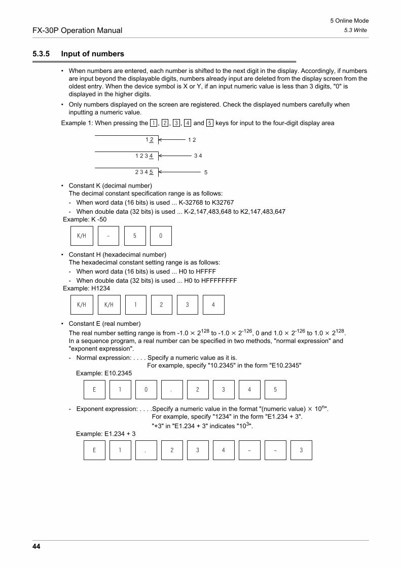
5 Online Mode
5.3 WriteFX-30P Operation Manual
5.3.5 Input of numbers
• When numbers are entered, each number is shifted to the next digit in the display. Accordingly, if numbers are input beyond the displayable digits, numbers already input are deleted from the display screen from the oldest entry. When the device symbol is X or Y, if an input numeric value is less than 3 digits, "0" is displayed in the higher digits.
• Only numbers displayed on the screen are registered. Check the displayed numbers carefully when inputting a numeric value.
Example 1: When pressing the , , , and keys for input to the four-digit display area
• Constant K (decimal number)The decimal constant specification range is as follows:
- When word data (16 bits) is used ... K-32768 to K32767
- When double data (32 bits) is used ... K-2,147,483,648 to K2,147,483,647 Example: K -50
• Constant H (hexadecimal number)The hexadecimal constant setting range is as follows:
- When word data (16 bits) is used ... H0 to HFFFF
- When double data (32 bits) is used ... H0 to HFFFFFFFF Example: H1234
• Constant E (real number)
The real number setting range is from -1.0 2128 to -1.0 2-126, 0 and 1.0 2-126 to 1.0 2128.In a sequence program, a real number can be specified in two methods, "normal expression" and "exponent expression".
- Normal expression: . . . . Specify a numeric value as it is.For example, specify "10.2345" in the form "E10.2345"
Example: E10.2345
- Exponent expression: . . . .Specify a numeric value in the format "(numeric value) 10n".For example, specify "1234" in the form "E1.234 + 3".
"+3" in "E1.234 + 3" indicates "103".Example: E1.234 + 3
1 21 2
1 2 3 4
2 3 4 5
3 4
5
44
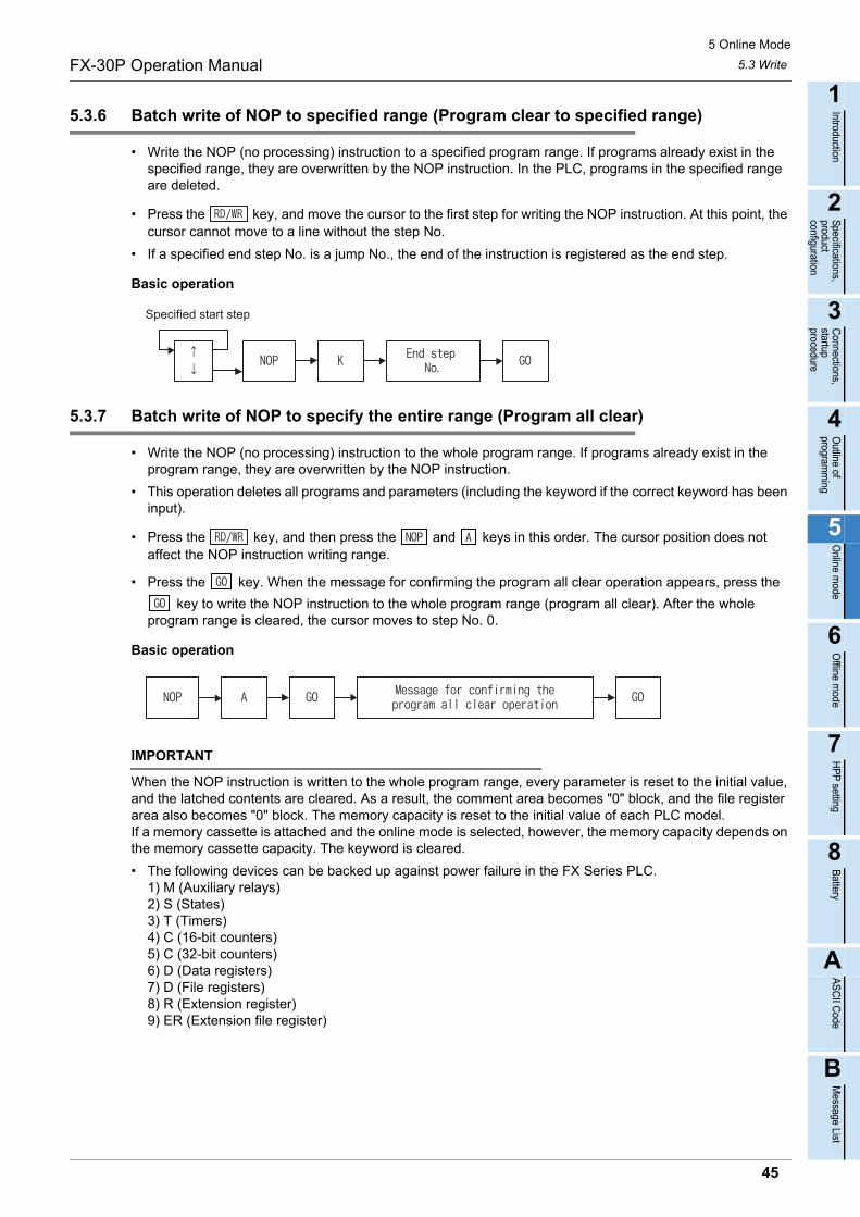
5 Online Mode
5.3 WriteFX-30P Operation Manual
1
Introduction
2
Specifications,product configuration
3
Connections,
startup procedure
4
Outline of
programm
ing
5
Online m
ode
6
Offline m
ode
7
HP
P setting
8
Battery
A
AS
CII C
ode
B
Message List
5.3.6 Batch write of NOP to specified range (Program clear to specified range)
• Write the NOP (no processing) instruction to a specified program range. If programs already exist in the specified range, they are overwritten by the NOP instruction. In the PLC, programs in the specified range are deleted.
• Press the key, and move the cursor to the first step for writing the NOP instruction. At this point, the cursor cannot move to a line without the step No.
• If a specified end step No. is a jump No., the end of the instruction is registered as the end step.
Basic operation
5.3.7 Batch write of NOP to specify the entire range (Program all clear)
• Write the NOP (no processing) instruction to the whole program range. If programs already exist in the program range, they are overwritten by the NOP instruction.
• This operation deletes all programs and parameters (including the keyword if the correct keyword has been input).
• Press the key, and then press the and keys in this order. The cursor position does not affect the NOP instruction writing range.
• Press the key. When the message for confirming the program all clear operation appears, press the
key to write the NOP instruction to the whole program range (program all clear). After the whole program range is cleared, the cursor moves to step No. 0.
Basic operation
IMPORTANT
When the NOP instruction is written to the whole program range, every parameter is reset to the initial value, and the latched contents are cleared. As a result, the comment area becomes "0" block, and the file register area also becomes "0" block. The memory capacity is reset to the initial value of each PLC model. If a memory cassette is attached and the online mode is selected, however, the memory capacity depends on the memory cassette capacity. The keyword is cleared.
• The following devices can be backed up against power failure in the FX Series PLC.1) M (Auxiliary relays)2) S (States)3) T (Timers) 4) C (16-bit counters)5) C (32-bit counters)6) D (Data registers)7) D (File registers)8) R (Extension register)9) ER (Extension file register)
Specified start step
45
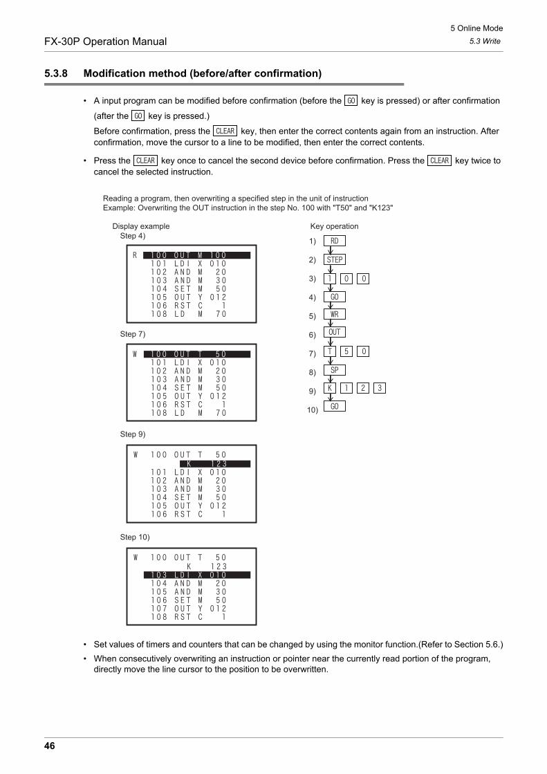
5 Online Mode
5.3 WriteFX-30P Operation Manual
5.3.8 Modification method (before/after confirmation)
• A input program can be modified before confirmation (before the key is pressed) or after confirmation
(after the key is pressed.)
Before confirmation, press the key, then enter the correct contents again from an instruction. After confirmation, move the cursor to a line to be modified, then enter the correct contents.
• Press the key once to cancel the second device before confirmation. Press the key twice to cancel the selected instruction.
• Set values of timers and counters that can be changed by using the monitor function.(Refer to Section 5.6.)
• When consecutively overwriting an instruction or pointer near the currently read portion of the program, directly move the line cursor to the position to be overwritten.
1)
2)
3)
4)
5)
6)
7)
8)
9)
10)
Reading a program, then overwriting a specified step in the unit of instruction Example: Overwriting the OUT instruction in the step No. 100 with "T50" and "K123"
Display example Key operationStep 4)
Step 7)
Step 9)
Step 10)
46
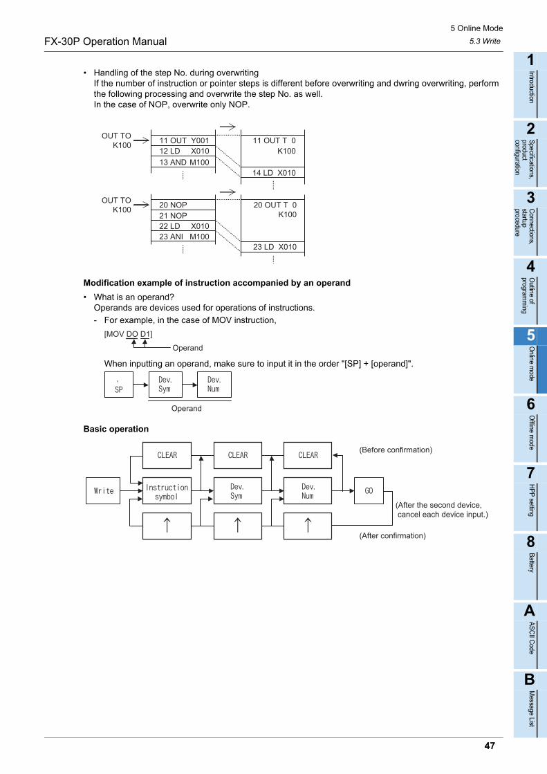
5 Online Mode
5.3 WriteFX-30P Operation Manual
1
Introduction
2
Specifications,product configuration
3
Connections,
startup procedure
4
Outline of
programm
ing
5
Online m
ode
6
Offline m
ode
7
HP
P setting
8
Battery
A
AS
CII C
ode
B
Message List
• Handling of the step No. during overwritingIf the number of instruction or pointer steps is different before overwriting and dwring overwriting, perform the following processing and overwrite the step No. as well.In the case of NOP, overwrite only NOP.
Modification example of instruction accompanied by an operand
• What is an operand?Operands are devices used for operations of instructions.
- For example, in the case of MOV instruction,
When inputting an operand, make sure to input it in the order "[SP] + [operand]".
Basic operation
OUT TOK100
OUT TOK100
11 OUT Y001 11 OUT T 012 LD X010 K100
13 AND 14 LD X010
20 NOP21 NOP22 LD 23 ANI M100
20 OUT T 0
23 LD X010
K100
M100
X010
Operand
[MOV DO D1]
Operand
(Before confirmation)
(After confirmation)
(After the second device, cancel each device input.)
47
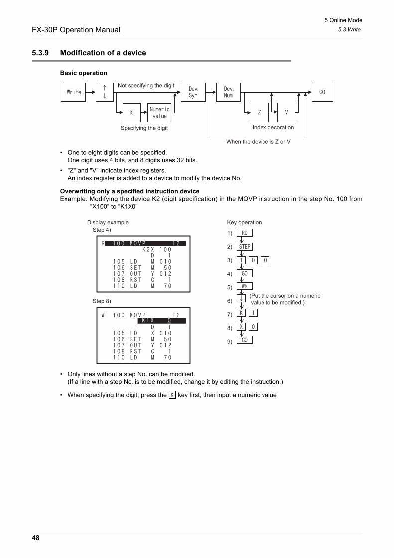
5 Online Mode
5.3 WriteFX-30P Operation Manual
5.3.9 Modification of a device
Basic operation
• One to eight digits can be specified.One digit uses 4 bits, and 8 digits uses 32 bits.
• "Z" and "V" indicate index registers.An index register is added to a device to modify the device No.
Overwriting only a specified instruction deviceExample: Modifying the device K2 (digit specification) in the MOVP instruction in the step No. 100 from
"X100" to "K1X0"
• Only lines without a step No. can be modified.(If a line with a step No. is to be modified, change it by editing the instruction.)
• When specifying the digit, press the key first, then input a numeric value
Not specifying the digit
Specifying the digit Index decoration
When the device is Z or V
Key operationDisplay example
(Put the cursor on a numeric value to be modified.)
1)
2)
3)
4)
5)
6)
7)
8)
9)
Step 4)
Step 8)
48

5 Online Mode
5.4 InsertFX-30P Operation Manual
1
Introduction
2
Specifications,product configuration
3
Connections,
startup procedure
4
Outline of
programm
ing
5
Online m
ode
6
Offline m
ode
7
HP
P setting
8
Battery
A
AS
CII C
ode
B
Message List
5.4 Insert
Press the key once to select the insert mode. Press the key again to select the deletemode. (The mode is selected alternately.)
5.4.1 Overview of the insert operation
In the online mode, a program is inserted into the memory in the PLC if a memory cassette is not attached tothe PLC.In the online mode, a program is inserted into a memory cassette (except EPROM cassettes) if it is attachedto the PLC. (When an EEPROM or FLROM cassette is attached, set the write protect switch to OFF.)In the offline mode, a program is inserted into the RAM in the FX-30P.Insertion is enabled when the PLC is in the STOP status.Read a program, and insert an instruction or pointer in a specified position.An instruction or pointer is inserted in a position above the step specified by the cursor. (Lines not displayingthe step No. cannot be specified.)After the inserted position, each step No. is automatically adjusted. (The display is shifted down.)When inserting an instruction or pointer near the currently read portion of the program, directly move the linecursor to the desired position.
Basic operation
• Insert operation condition
*1. When an EEPROM or FLROM cassette is attached to the PLC, insertion is enabled only while thewrite protect switch is OFF.
<Online mode>
- Instructions and pointers are inserted into a program stored in the memory of the PLC.
- Instructions and pointers are inserted into a program stored in a memory cassette (except EPROM cassette) If it is attached to the PLC.
- Insertion is enabled when the PLC is in STOP status.<Offline mode>
- Instructions and pointers are inserted into a program stored in the RAM in the FX-30P.
- Insertion is enabled into a program stored in the flash memory in the FX-30P after the program is transferred from the flash memory to the RAM in the FX-30P.
PLC status PLC memory
RUN STOP Built in memory RAM cassetteEEPROM cassetteFLROM cassette
EPROM cassette
- *1 -
Specified first device
Inserted an instruction
Specify a pointer/Interrupt No.
Specified second device
49
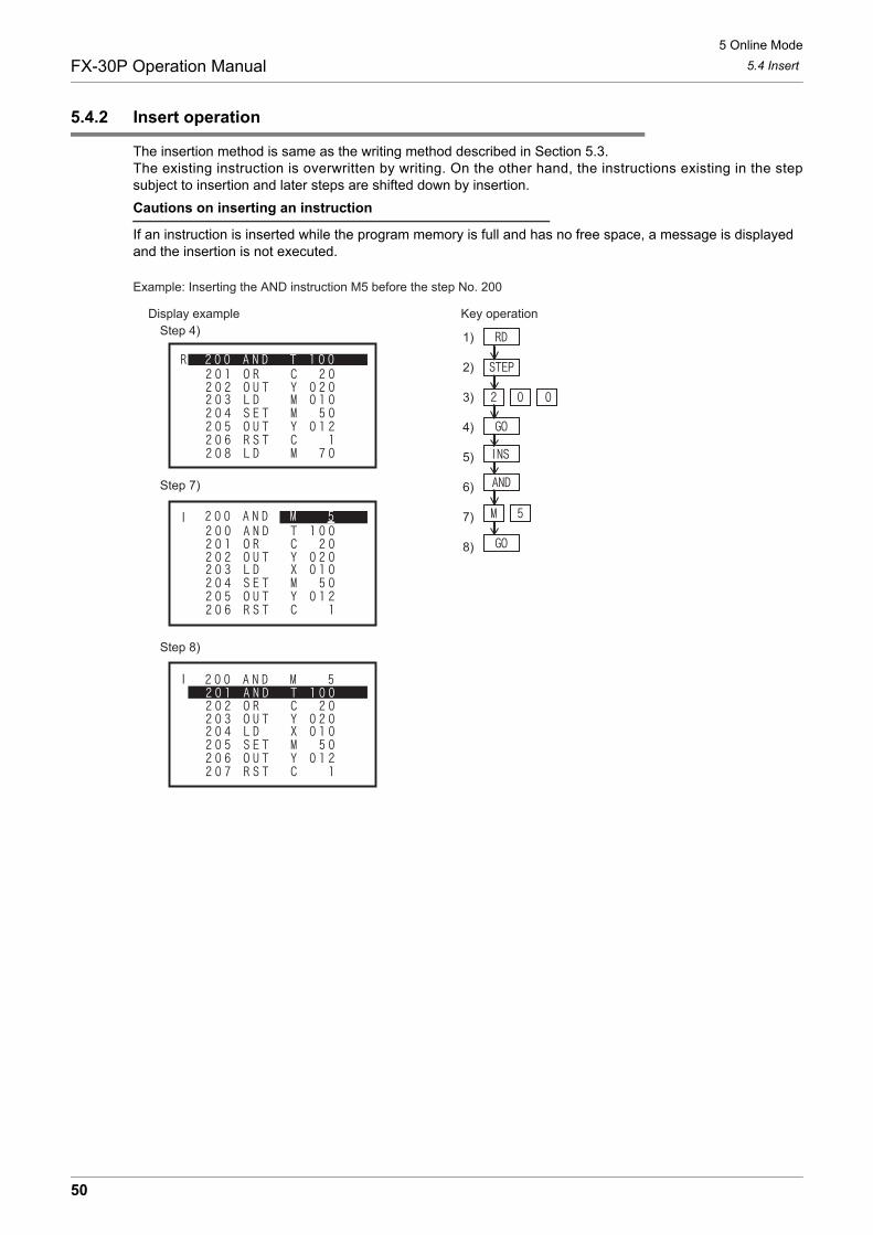
5 Online Mode
5.4 InsertFX-30P Operation Manual
5.4.2 Insert operation
The insertion method is same as the writing method described in Section 5.3.The existing instruction is overwritten by writing. On the other hand, the instructions existing in the stepsubject to insertion and later steps are shifted down by insertion.
Cautions on inserting an instruction
If an instruction is inserted while the program memory is full and has no free space, a message is displayed and the insertion is not executed.
Key operationDisplay exampleStep 4)
Step 7)
Step 8)
1)
2)
3)
4)
5)
6)
7)
8)
Example: Inserting the AND instruction M5 before the step No. 200
50
5 Online Mode
5.5 DeleteFX-30P Operation Manual
1
Introduction
2
Specifications,product configuration
3
Connections,
startup procedure
4
Outline of
programm
ing
5
Online m
ode
6
Offline m
ode
7
HP
P setting
8
Battery
A
AS
CII C
ode
B
Message List
5.5 Delete
Press the key once to select the insert mode. Press the key twice to select the deletemode. (The mode is selected alternately.)
5.5.1 Overview of the delete operation
Read a program, and delete an instruction, pointer or NOP.
• Delete operation condition
*1. When an EEPROM or FLROM cassette is attached to the PLC, deletion is enabled only while thewrite protect switch is OFF.
<Online mode>
- Instructions and pointers are deleted from a program stored in the memory of the PLC.
- Instructions and pointers are deleted from a program stored in a memory cassette (except EPROM cassette) if it is attached to the PLC.
- Deletion is enabled while the PLC is in the STOP status.<Offline mode>
- Instructions and pointers are deleted from a program stored in the RAM in the FX-30P.
- Deletion is enabled from a program stored in the flash memory in the FX-30P after the program is transferred from the flash memory to the RAM in the FX-30P.
PLC status PLC memory
RUN STOP Built in memory RAM cassetteEEPROM cassetteFLROM cassette
EPROM cassette
- *1 -
51

5 Online Mode
5.5 DeleteFX-30P Operation Manual
5.5.2 Deletion of instructions and pointers
Basic operation
• Using operation above, the instruction in the cursor position is deleted.For instructions which use two or more lines such as set values of timers and counters and operands of applied instructions, when the instruction part, set value, or operand is deleted, all lines are deleted at the same time.
• After the deleted position, each step No. is automatically adjusted. (The display is shifted up.)
Objectspecification
Key operationDisplay example
Select the delete function
1)
2)
3)
4)
5)
6)
7)
Example: Deleting "AND M10" in the step No. 10
Step 6)
Step 7)
52
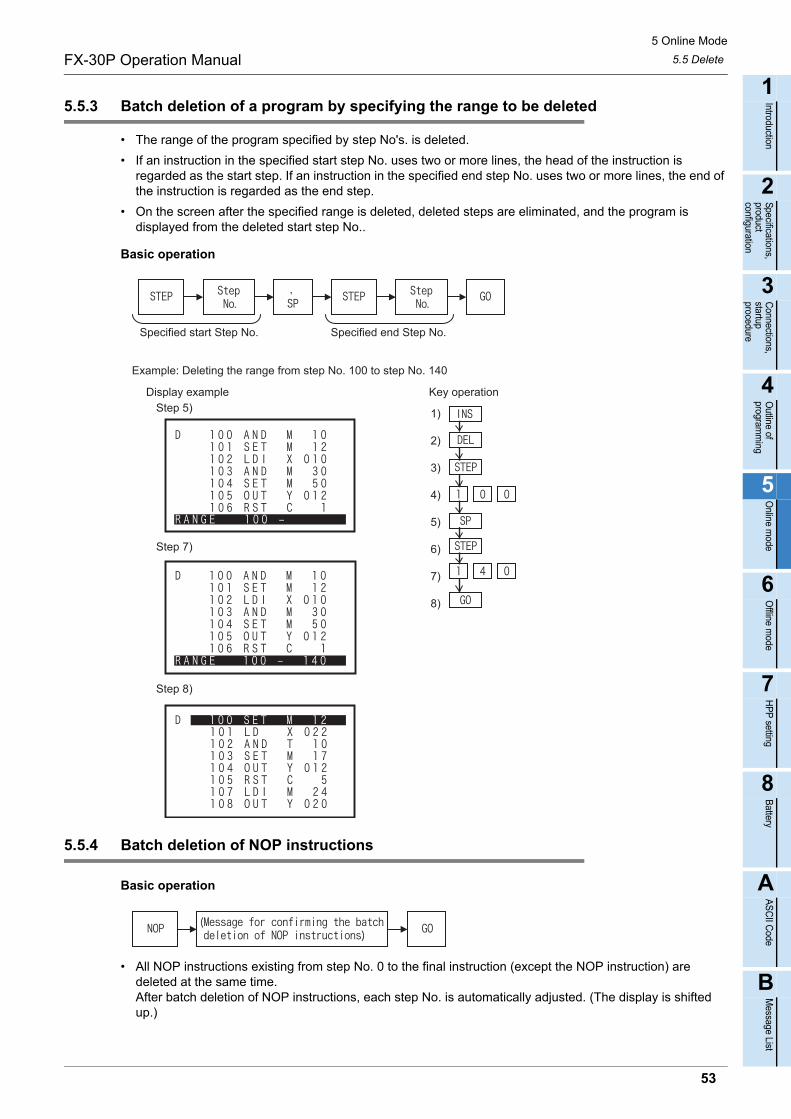
5 Online Mode
5.5 DeleteFX-30P Operation Manual
1
Introduction
2
Specifications,product configuration
3
Connections,
startup procedure
4
Outline of
programm
ing
5
Online m
ode
6
Offline m
ode
7
HP
P setting
8
Battery
A
AS
CII C
ode
B
Message List
5.5.3 Batch deletion of a program by specifying the range to be deleted
• The range of the program specified by step No's. is deleted.
• If an instruction in the specified start step No. uses two or more lines, the head of the instruction is regarded as the start step. If an instruction in the specified end step No. uses two or more lines, the end of the instruction is regarded as the end step.
• On the screen after the specified range is deleted, deleted steps are eliminated, and the program is displayed from the deleted start step No..
Basic operation
5.5.4 Batch deletion of NOP instructions
Basic operation
• All NOP instructions existing from step No. 0 to the final instruction (except the NOP instruction) are deleted at the same time.After batch deletion of NOP instructions, each step No. is automatically adjusted. (The display is shifted up.)
Specified start Step No. Specified end Step No.
Key operationDisplay example
1)
2)
3)
4)
5)
6)
7)
8)
Example: Deleting the range from step No. 100 to step No. 140
Step 5)
Step 7)
Step 8)
53

5 Online Mode
5.6 MonitorFX-30P Operation Manual
5.6 Monitor
Press the key once to select the monitor function. Press the key again to select the testfunction. (The function is selected alternately.)
5.6.1 Overview of the monitor operation
Display the PLC operation status on the 30P. (The monitor operation is available even when the PLC is in theSTOP status.)The monitor operation is valid only when the online mode is selected.(If the offline mode is selected when the 30P started up, it can be changed to the online mode by using theothers function.)
• Monitor operation condition
- The PLC operation status is displayed in the FX-30P.
- The monitor function is valid only in the online mode.
The screen display
1) ModeIndicates the monitor mode (M).
2) Line cursorMoves among lines, and specifies a line to be tested.
3) DeviceIndicates the device symbol and device number.
4) Present value or T/C set valueDisplays the present value of devices and the set value of timers and counters.
5) T/C coil/contact ON/OFF statusDisplays the ON/OFF status of coils and contacts of timers and counters. I: Coil ON/OFF status P: Contact ON/OFF status R: Reset image U: Up/down-counter status (-: OFF, : ON)
PLC status PLC memory
RUN STOP Built in memory RAM cassetteEEPROM cassetteFLROM cassette
EPROM cassette
1)
2)
3) 4)
5)21half-width 8lines
54
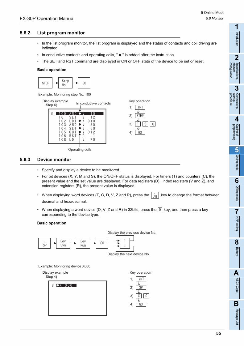
5 Online Mode
5.6 MonitorFX-30P Operation Manual
1
Introduction
2
Specifications,product configuration
3
Connections,
startup procedure
4
Outline of
programm
ing
5
Online m
ode
6
Offline m
ode
7
HP
P setting
8
Battery
A
AS
CII C
ode
B
Message List
5.6.2 List program monitor
• In the list program monitor, the list program is displayed and the status of contacts and coil driving are indicated.
• In conductive contacts and operating coils, " " is added after the instruction.
• The SET and RST command are displayed in ON or OFF state of the device to be set or reset.
Basic operation
5.6.3 Device monitor
• Specify and display a device to be monitored.
• For bit devices (X, Y, M and S), the ON/OFF status is displayed. For timers (T) and counters (C), the present value and the set value are displayed. For data registers (D) , index registers (V and Z), and extension registers (R), the present value is displayed.
• When displaying word devices (T, C, D, V, Z and R), press the key to change the format between
decimal and hexadecimal.
• When displaying a word device (D, V, Z and R) in 32bits, press the key, and then press a key corresponding to the device type.
Basic operation
Key operationIn conductive contacts
Display exampleStep 6)
1)
2)
3)
4)
Example: Monitoring step No. 100
Operating coils
Display the previous device No.
Display the next device No.
Key operationDisplay example
1)
2)
3)
4)
Example: Monitoring device X000
Step 4)
55

5 Online Mode
5.6 MonitorFX-30P Operation Manual
• When the set value is indirectly specified through a data register (D), the data register No and the present value of the data register are displayed as the set value.
5.6.4 Operation state monitor
• When a step ladder type program is running in the PLC, up to eight operating states can be displayed.
• As the state changes, displayed No’s. automatically indicate the operation process of the machine.
• Only the states in the range from S0 to S899, S1000 to S4095 can be monitored. S900 to S999 (for annunciators) are ignored.
• Before executing the operation state monitor, set M8047 (STL monitor valid) to ON in the PLC.
Basic operation
Monitoring annunciators
If M8049 is set to ON, the smallest No. of operating states among S900 to S999 can be monitoredthrough the operation above.
Key operationDisplay exampleStep 4) Present value
Set value
1)
2)
3)
4)
Example: Monitoring device T0 Decimal displayIn hexadecimal display,"H" is displayed.
I : ON/OFF status of the coilP: ON/OFF status of the contactR: Reset image(-: OFF, : ON)
Display exampleWhen the set value is specified indirectly
Data register No. Present value ofdata register
Display exampleOperation state monitor When M8047 (STL monitor) is set to OFF
56

5 Online Mode
5.7 TestFX-30P Operation Manual
1
Introduction
2
Specifications,product configuration
3
Connections,
startup procedure
4
Outline of
programm
ing
5
Online m
ode
6
Offline m
ode
7
HP
P setting
8
Battery
A
AS
CII C
ode
B
Message List
5.7 Test
Press the key once to select the monitor function. Press the key again to select the testfunction. (The function is selected alternately.)
5.7.1 Overview of the test function
In the test mode, devices in the PLC can be forcibly set to ON/OFF, present values of word devices (T, C, D,V, Z and R) in the PLC can be changed, and set values of timers (T) and counters (C) in the PLC can bechanged from the HPP. Perform the device monitor operation to display devices in the PLC to be changed.
• Test operation condition
*1. The set value of timers and counters cannot be changed while an EEPROM cassette or FLROMcassette is attached to the PLC and the PLC is in the RUN status. When the protect switch is ON, setvalues cannot be changed.
*2. The set value of timers and counters cannot be changed while an EPROM cassette is attached to thePLC.
- Turn ON or OFF devices forcibly, change the set value of word devices, and change the set value of timers and counters.
- The test function is valid only in the online mode.
The screen display
1) ModeIndicates the test mode (T).
2) Line cursorMoves among lines, and specifies a line to be tested.
3) DeviceIndicates the device symbol and device number.
4) Present value or T/C set valueDisplays the present value of devices and the set value of timers and counters.
5) T/C coil/contact ON/OFF statusDisplays the ON/OFF status of coils and contacts of timers and counters. I: Coil ON/OFF status P: Contact ON/OFF status R: Reset image U: Up/down-counter status (-: OFF, : ON)
OPERATION PRECAUTIONS
• Thoroughly read the manual and sufficiently assure safety before executing the operation to forcibly set devices to ON/OFF or theoperation to change present values and set values of word devices in the test mode.Otherwise, the machine may be damaged and accidents may occur by erroneous operations.
PLC status PLC memory
RUN STOP Built in memory RAM cassetteEEPROM cassetteFLROM cassette
EPROM cassette
*1 *2
1)
2)
3) 4)
5)21half-width 8lines
57
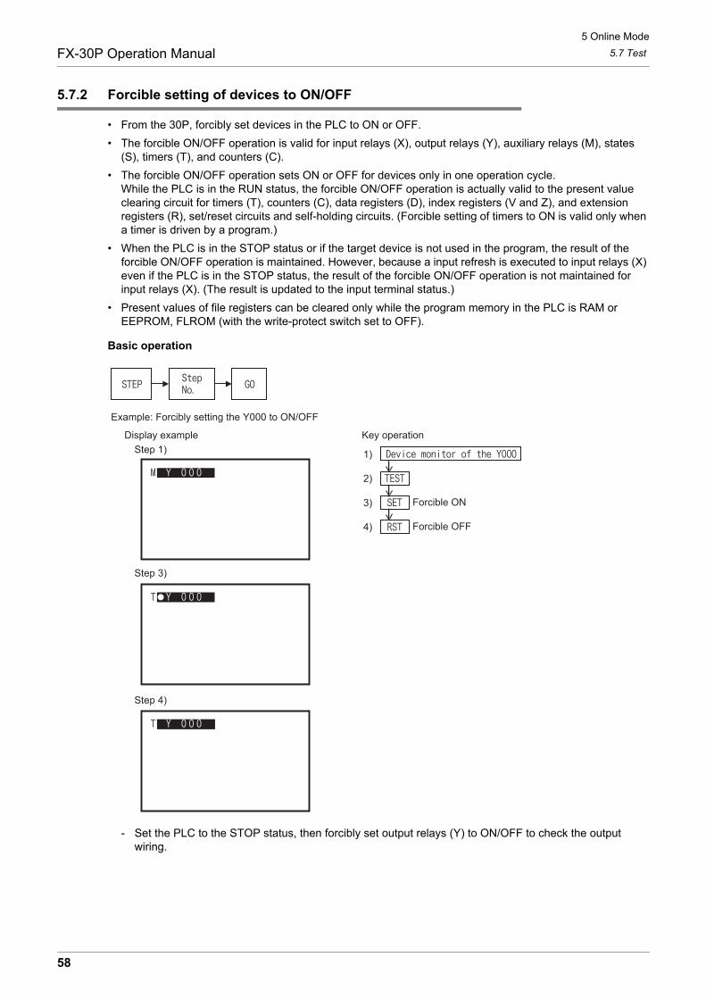
5 Online Mode
5.7 TestFX-30P Operation Manual
5.7.2 Forcible setting of devices to ON/OFF
• From the 30P, forcibly set devices in the PLC to ON or OFF.
• The forcible ON/OFF operation is valid for input relays (X), output relays (Y), auxiliary relays (M), states (S), timers (T), and counters (C).
• The forcible ON/OFF operation sets ON or OFF for devices only in one operation cycle.While the PLC is in the RUN status, the forcible ON/OFF operation is actually valid to the present value clearing circuit for timers (T), counters (C), data registers (D), index registers (V and Z), and extension registers (R), set/reset circuits and self-holding circuits. (Forcible setting of timers to ON is valid only when a timer is driven by a program.)
• When the PLC is in the STOP status or if the target device is not used in the program, the result of the forcible ON/OFF operation is maintained. However, because a input refresh is executed to input relays (X) even if the PLC is in the STOP status, the result of the forcible ON/OFF operation is not maintained for input relays (X). (The result is updated to the input terminal status.)
• Present values of file registers can be cleared only while the program memory in the PLC is RAM or EEPROM, FLROM (with the write-protect switch set to OFF).
Basic operation
- Set the PLC to the STOP status, then forcibly set output relays (Y) to ON/OFF to check the output wiring.
Key operationDisplay example
1)
2)
3)
4)
Example: Forcibly setting the Y000 to ON/OFF
Forcible ON
Forcible OFF
Step 1)
Step 3)
Step 4)
58
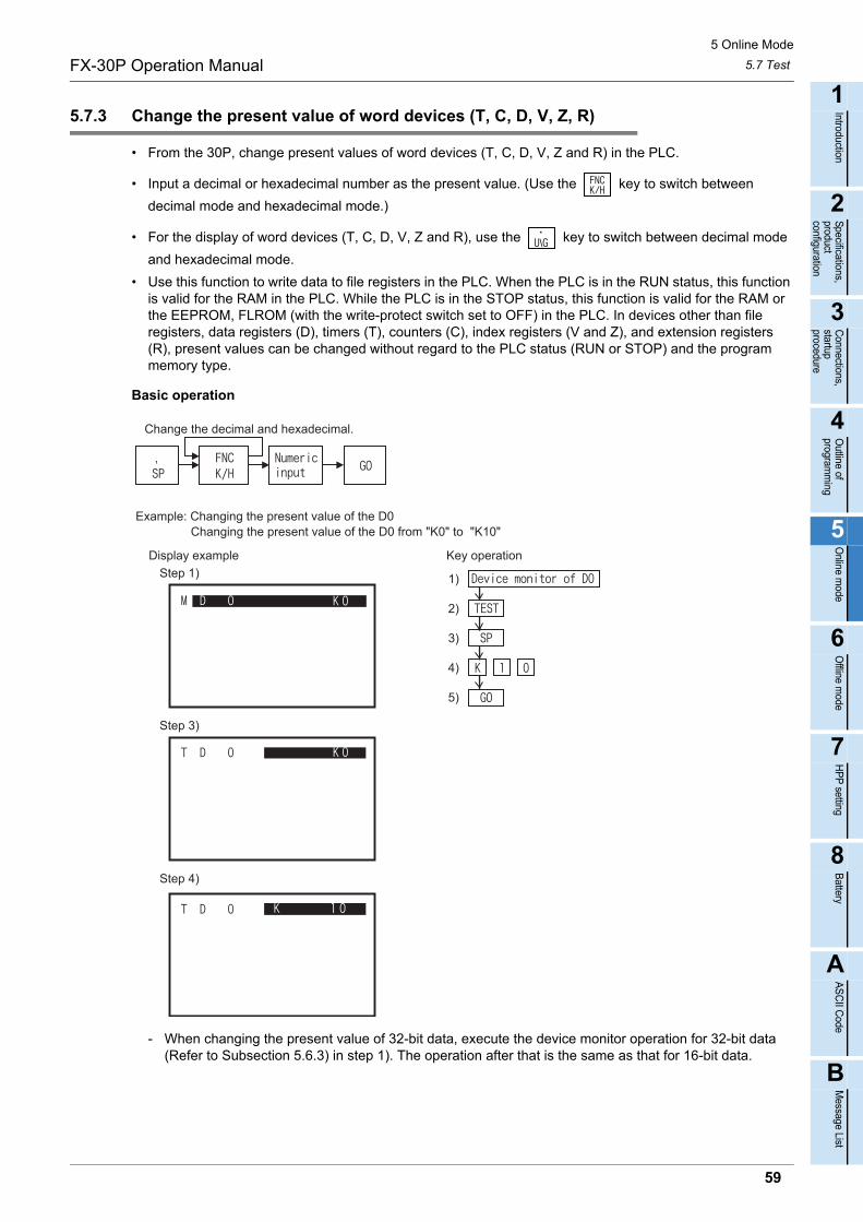
5 Online Mode
5.7 TestFX-30P Operation Manual
1
Introduction
2
Specifications,product configuration
3
Connections,
startup procedure
4
Outline of
programm
ing
5
Online m
ode
6
Offline m
ode
7
HP
P setting
8
Battery
A
AS
CII C
ode
B
Message List
5.7.3 Change the present value of word devices (T, C, D, V, Z, R)
• From the 30P, change present values of word devices (T, C, D, V, Z and R) in the PLC.
• Input a decimal or hexadecimal number as the present value. (Use the key to switch between
decimal mode and hexadecimal mode.)
• For the display of word devices (T, C, D, V, Z and R), use the key to switch between decimal mode
and hexadecimal mode.
• Use this function to write data to file registers in the PLC. When the PLC is in the RUN status, this function is valid for the RAM in the PLC. While the PLC is in the STOP status, this function is valid for the RAM or the EEPROM, FLROM (with the write-protect switch set to OFF) in the PLC. In devices other than file registers, data registers (D), timers (T), counters (C), index registers (V and Z), and extension registers (R), present values can be changed without regard to the PLC status (RUN or STOP) and the program memory type.
Basic operation
- When changing the present value of 32-bit data, execute the device monitor operation for 32-bit data (Refer to Subsection 5.6.3) in step 1). The operation after that is the same as that for 16-bit data.
Change the decimal and hexadecimal.
Key operationDisplay example
Example: Changing the present value of the D0Changing the present value of the D0 from "K0" to "K10"
1)
2)
3)
4)
5)
Step 1)
Step 3)
Step 4)
59

5 Online Mode
5.7 TestFX-30P Operation Manual
5.7.4 Change the set value of timers (T) and counters (C)
• From the 30P, change set values of timers (T) and counters (C) existing in programs in the PLC.
• While the PLC is in RUN status, set values can be changed if the program memory is in the RAM. While the PLC is in STOP status, set values can be changed if the program memory is in the RAM or the EEPROM, FLROM (with the write-protect switch set to OFF).
• Set values can be changed in two ways: by changing the device monitor to test mode and by changing the list program monitor to test mode. If a set value is changed by using the device monitor in test mode, the timer (T) or the counter (C) nearest to step No. 0 in the program is automatically regarded as the target. When changing the set value of a timer (T) or counter (C) having same No., select a desired timer (T) or counter (C) in the list program monitor, then change its set value.
Basic operation
- Operation to change the device monitor to test mode.
- Operation to change the list program monitor to test mode.
Indirect specification through device
Switch between decimaland hexadecimal.
Direct specification by numeric value
Indirect specification through device
Switch between decimaland hexadecimal.
Direct specification by numeric value
Objectspecification
60
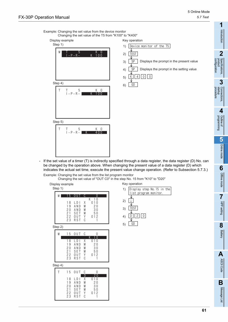
5 Online Mode
5.7 TestFX-30P Operation Manual
1
Introduction
2
Specifications,product configuration
3
Connections,
startup procedure
4
Outline of
programm
ing
5
Online m
ode
6
Offline m
ode
7
HP
P setting
8
Battery
A
AS
CII C
ode
B
Message List
- If the set value of a timer (T) is indirectly specified through a data register, the data register (D) No. can be changed by the operation above. When changing the present value of a data register (D) which indicates the actual set time, execute the present value change operation. (Refer to Subsection 5.7.3.)
Key operationDisplay exampleStep 1)
Step 4)
Step 5)
1)
2)
3)
4)
5)
6)
Changing the set value of the T5 from "K100" to "K400" Example: Changing the set value from the device monitor
Displays the prompt in the present value
Displays the prompt in the setting value
Key operationDisplay exampleStep 1)
Step 2)
Step 4)
1)
2)
3)
4)
5)
Changing the set value of "OUT C0" in the step No. 15 from "K10" to "D20" Example: Changing the set value from the list program monitor
61
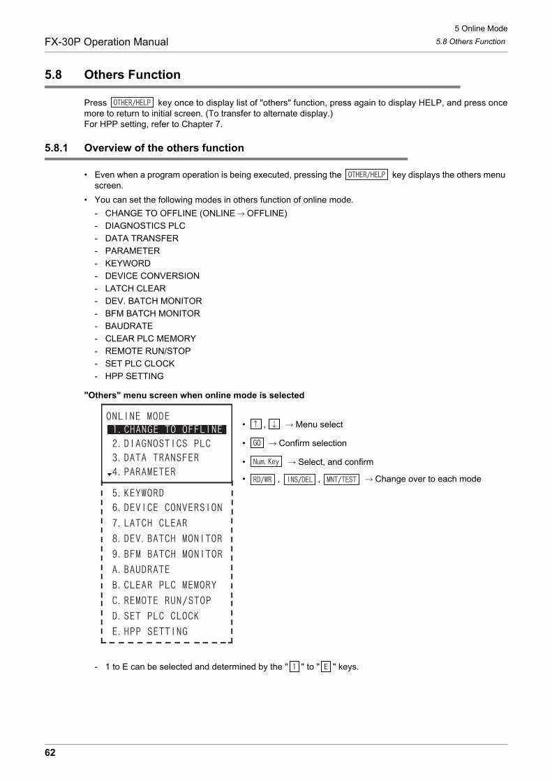
5 Online Mode
5.8 Others FunctionFX-30P Operation Manual
5.8 Others Function
Press key once to display list of "others" function, press again to display HELP, and press oncemore to return to initial screen. (To transfer to alternate display.)For HPP setting, refer to Chapter 7.
5.8.1 Overview of the others function
• Even when a program operation is being executed, pressing the key displays the others menu screen.
• You can set the following modes in others function of online mode.
- CHANGE TO OFFLINE (ONLINE OFFLINE)
- DIAGNOSTICS PLC
- DATA TRANSFER
- PARAMETER
- KEYWORD
- DEVICE CONVERSION
- LATCH CLEAR
- DEV. BATCH MONITOR
- BFM BATCH MONITOR
- BAUDRATE
- CLEAR PLC MEMORY
- REMOTE RUN/STOP
- SET PLC CLOCK
- HPP SETTING
"Others" menu screen when online mode is selected
• , Menu select
• Confirm selection
• Select, and confirm
• , , Change over to each mode
- 1 to E can be selected and determined by the " " to " " keys.
62

5 Online Mode
5.8 Others FunctionFX-30P Operation Manual
1
Introduction
2
Specifications,product configuration
3
Connections,
startup procedure
4
Outline of
programm
ing
5
Online m
ode
6
Offline m
ode
7
HP
P setting
8
Battery
A
AS
CII C
ode
B
Message List
5.8.2 Change to offline
To change to offline mode.
• Offline change-over condition
The screen display
• Offline change execution
• Return to other menu
- When offline mode is selected first time after shipping or after HPP initialization.
• , Select PLC type
• Confirm selection
• Select and confirm
• Return to other menu
- When HPP protection is activated.
• protection key input
• Delete one character
• Confirm input
• Return to other menu
• When HPP protect keys are mismatched.
• Return to protection key input screen
PLC status PLC memory
RUN STOP Built in memory RAM cassetteEEPROM cassetteFLROM cassette
EPROM cassette
63
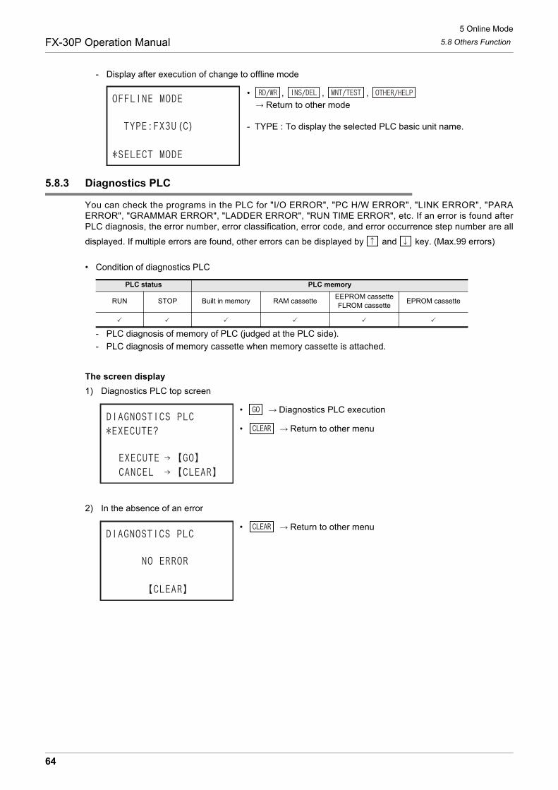
5 Online Mode
5.8 Others FunctionFX-30P Operation Manual
- Display after execution of change to offline mode
• , , , Return to other mode
- TYPE : To display the selected PLC basic unit name.
5.8.3 Diagnostics PLC
You can check the programs in the PLC for "I/O ERROR", "PC H/W ERROR", "LINK ERROR", "PARAERROR", "GRAMMAR ERROR", "LADDER ERROR", "RUN TIME ERROR", etc. If an error is found afterPLC diagnosis, the error number, error classification, error code, and error occurrence step number are all
displayed. If multiple errors are found, other errors can be displayed by and key. (Max.99 errors)
• Condition of diagnostics PLC
- PLC diagnosis of memory of PLC (judged at the PLC side).
- PLC diagnosis of memory cassette when memory cassette is attached.
The screen display
1) Diagnostics PLC top screen
• Diagnostics PLC execution
• Return to other menu
2) In the absence of an error
• Return to other menu
PLC status PLC memory
RUN STOP Built in memory RAM cassetteEEPROM cassetteFLROM cassette
EPROM cassette
64
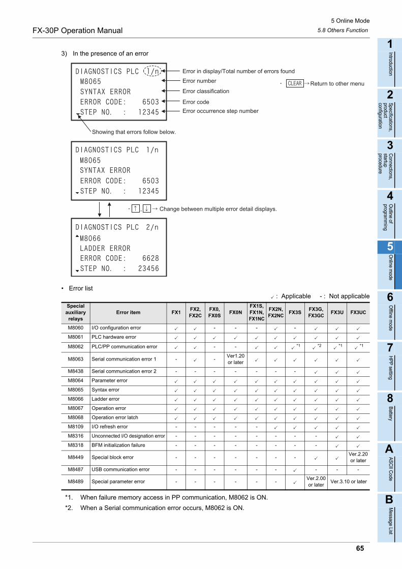
5 Online Mode
5.8 Others FunctionFX-30P Operation Manual
1
Introduction
2
Specifications,product configuration
3
Connections,
startup procedure
4
Outline of
programm
ing
5
Online m
ode
6
Offline m
ode
7
HP
P setting
8
Battery
A
AS
CII C
ode
B
Message List
3) In the presence of an error
• Error list: Applicable - : Not applicable
*1. When failure memory access in PP communication, M8062 is ON.
*2. When a Serial communication error occurs, M8062 is ON.
Special auxiliary
relaysError item FX1
FX2,FX2C
FX0,FX0S
FX0NFX1S,FX1N,FX1NC
FX2N,FX2NC
FX3SFX3G,FX3GC
FX3U FX3UC
M8060 I/O configuration error - - - -
M8061 PLC hardware error
M8062 PLC/PP communication error - - *1 *2 *1 *1
M8063 Serial communication error 1 - -Ver1.20or later
M8438 Serial communication error 2 - - - - - - -
M8064 Parameter error
M8065 Syntax error
M8066 Ladder error
M8067 Operation error
M8068 Operation error latch
M8109 I/O refresh error - - - - -
M8316 Unconnected I/O designation error - - - - - - - -
M8318 BFM initialization failure - - - - - - - -
M8449 Special block error - - - - - - -Ver.2.20or later
M8487 USB communication error - - - - - - - - -
M8489 Special parameter error - - - - - -Ver.2.00or later
Ver.3.10 or later
Error in display/Total number of errors found
Showing that errors follow below.
Error number
Error classification
Error code
Error occurrence step number
Change between multiple error detail displays.
Return to other menu
65

5 Online Mode
5.8 Others FunctionFX-30P Operation Manual
5.8.4 Memory cassette transfer
• You can transfer or collate the program or parameter between PLC memory and memory cassette.
• The HPP automatically identifies the memory cassette type, then displays it.
• After creating or changing a program in the RAM, where it takes less time to write to, the program can be executed to operate the PLC from the EEPROM and FLROM, which have better storage capability.
• Transfer is disabled from a memory with a larger capacity to a memory that has a smaller capacity. (Such a transfer causes a parameter error.) In such a case change the parameters for the memory cassette first, then execute the transfer function again.
• After transfer of program, the 30P collates automatically, and confirms that the contents of the both are the same. As a result of collating, if the program is not identical, "VERIFY ERROR!" is displayed, and the step number of mismatches are also displayed at the same time.
• Condition of memory cassette transfer
*1. When an EEPROM or FLROM cassette is attached, only when the protect switch is OFF, you cantransfer from built in PLC memory to the memory cassette.
*2. When an EPROM cassette is attached, you cannot transfer from built in PLC memory to the memorycassette.
The screen display and operation method
1) Memory cassette transfer top screenThe type of PLC memory is automatically determined by 30P, and the display differs in each case. -For RAM : FX-RAM -For EEPROM : FX-EEPROMThe type of memory cassette is automatically determined by 30P, and the display differs in each case. -For an EEPROM cassette : CS-EEPROM -For an EPROM cassette : CS-EPROM -For a FLROM cassette : CS-FLROM -For a RAM cassette : CS-RAM
- When the PLC memory is RAM, and EEPROM cassette is attached.
• , Select transfer direction
• Confirm selection
• Select and confirm
• Return to other menu
- When the PLC memory is RAM, and EPROM cassette is attached.
• , Select transfer direction
• Confirm selection
• Select and confirm
• Return to other menu
PLC status PLC memory
RUN STOP Built in memory RAM cassetteEEPROM cassetteFLROM cassette
EPROM cassette
- *1 *2
66
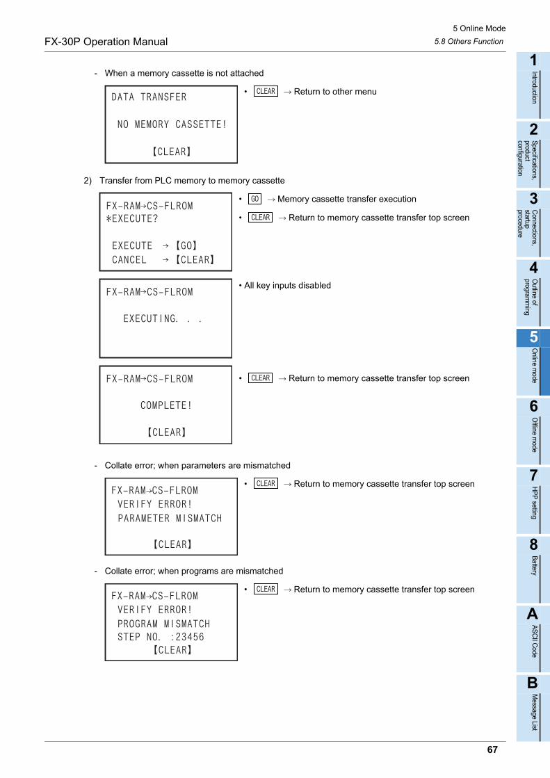
5 Online Mode
5.8 Others FunctionFX-30P Operation Manual
1
Introduction
2
Specifications,product configuration
3
Connections,
startup procedure
4
Outline of
programm
ing
5
Online m
ode
6
Offline m
ode
7
HP
P setting
8
Battery
A
AS
CII C
ode
B
Message List
- When a memory cassette is not attached
• Return to other menu
2) Transfer from PLC memory to memory cassette
• Memory cassette transfer execution
• Return to memory cassette transfer top screen
• All key inputs disabled
• Return to memory cassette transfer top screen
- Collate error; when parameters are mismatched
• Return to memory cassette transfer top screen
- Collate error; when programs are mismatched
• Return to memory cassette transfer top screen
67
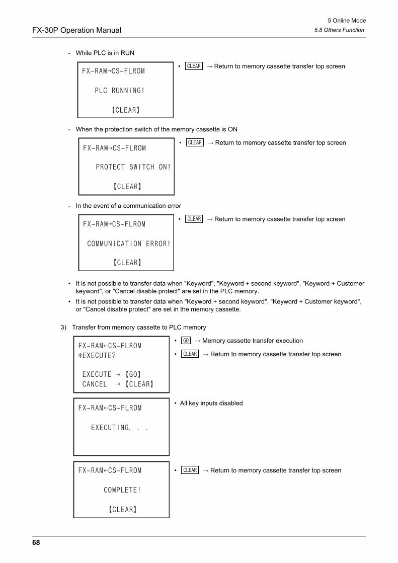
5 Online Mode
5.8 Others FunctionFX-30P Operation Manual
- While PLC is in RUN
• Return to memory cassette transfer top screen
- When the protection switch of the memory cassette is ON
• Return to memory cassette transfer top screen
- In the event of a communication error
• Return to memory cassette transfer top screen
• It is not possible to transfer data when "Keyword", "Keyword + second keyword", "Keyword + Customer keyword", or "Cancel disable protect" are set in the PLC memory.
• It is not possible to transfer data when "Keyword + second keyword", "Keyword + Customer keyword", or "Cancel disable protect" are set in the memory cassette.
3) Transfer from memory cassette to PLC memory
• Memory cassette transfer execution
• Return to memory cassette transfer top screen
• All key inputs disabled
• Return to memory cassette transfer top screen
68

5 Online Mode
5.8 Others FunctionFX-30P Operation Manual
1
Introduction
2
Specifications,product configuration
3
Connections,
startup procedure
4
Outline of
programm
ing
5
Online m
ode
6
Offline m
ode
7
HP
P setting
8
Battery
A
AS
CII C
ode
B
Message List
- Collate error; when parameters are mismatched
• Return to memory cassette transfer top screen
- Collate error; when programs are mismatched
• Return to memory cassette transfer top screen
- While PLC is in RUN
• Return to memory cassette transfer top screen
- In the event of a communication error
• Return to memory cassette transfer top screen
• It is not possible to transfer data when "Keyword + second keyword", "Keyword + Customer keyword", or "Cancel disable protect" are set in the PLC memory or the memory cassette.
69
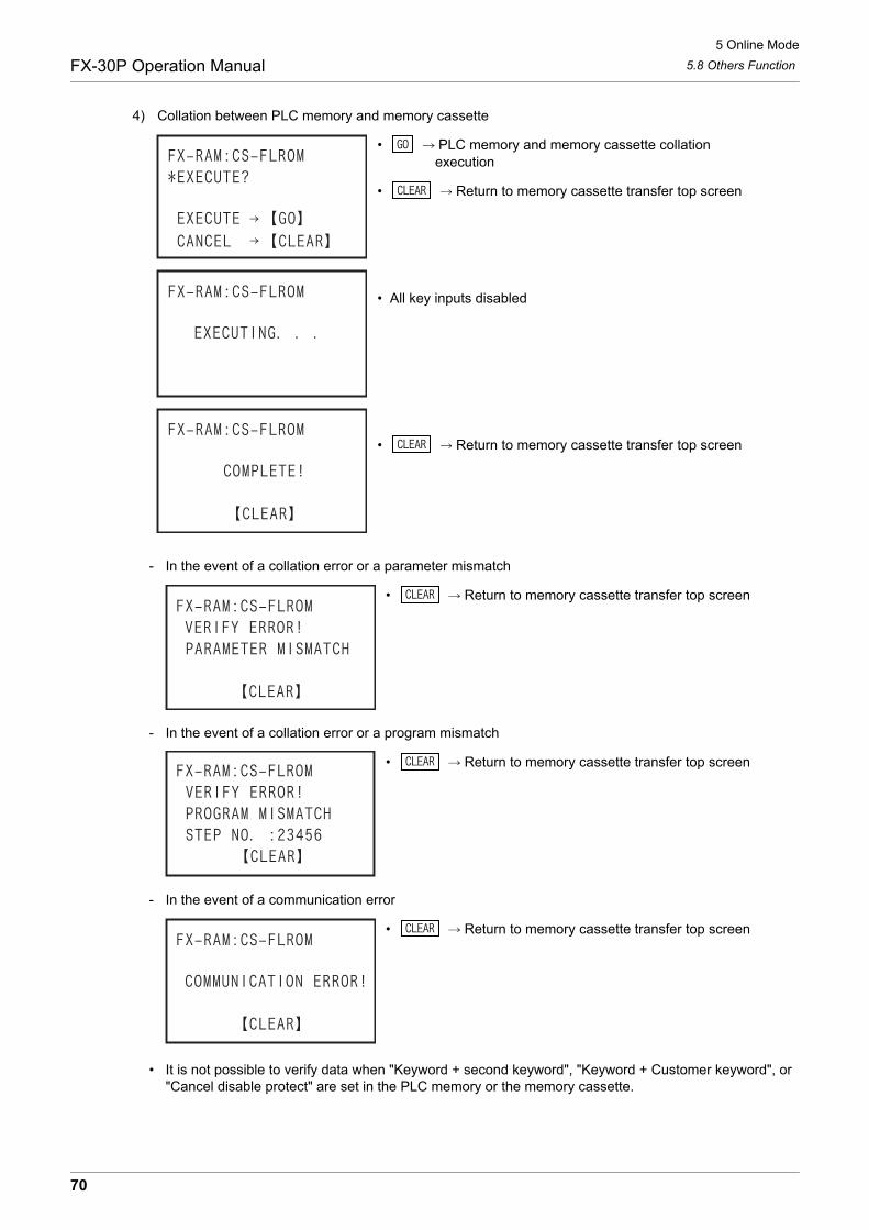
5 Online Mode
5.8 Others FunctionFX-30P Operation Manual
4) Collation between PLC memory and memory cassette
• PLC memory and memory cassette collation execution
• Return to memory cassette transfer top screen
• All key inputs disabled
• Return to memory cassette transfer top screen
- In the event of a collation error or a parameter mismatch
• Return to memory cassette transfer top screen
- In the event of a collation error or a program mismatch
• Return to memory cassette transfer top screen
- In the event of a communication error
• Return to memory cassette transfer top screen
• It is not possible to verify data when "Keyword + second keyword", "Keyword + Customer keyword", or "Cancel disable protect" are set in the PLC memory or the memory cassette.
70
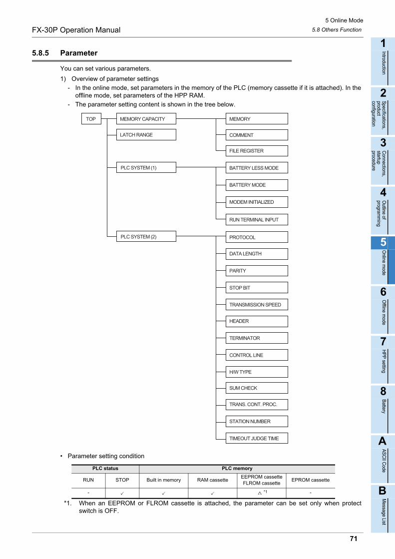
5 Online Mode
5.8 Others FunctionFX-30P Operation Manual
1
Introduction
2
Specifications,product configuration
3
Connections,
startup procedure
4
Outline of
programm
ing
5
Online m
ode
6
Offline m
ode
7
HP
P setting
8
Battery
A
AS
CII C
ode
B
Message List
5.8.5 Parameter
You can set various parameters.
1) Overview of parameter settings
- In the online mode, set parameters in the memory of the PLC (memory cassette if it is attached). In the offline mode, set parameters of the HPP RAM.
- The parameter setting content is shown in the tree below.
• Parameter setting condition
*1. When an EEPROM or FLROM cassette is attached, the parameter can be set only when protectswitch is OFF.
PLC status PLC memory
RUN STOP Built in memory RAM cassetteEEPROM cassetteFLROM cassette
EPROM cassette
- *1 -
TOP MEMORY CAPACITY MEMORY
COMMENT
BATTERY LESS MODE
LATCH RANGE
PLC SYSTEM (1)
PLC SYSTEM (2)
RUN TERMINAL INPUT
MODEM INITIALIZED
BATTERY MODE
PROTOCOL
STOP BIT
PARITY
DATA LENGTH
TRANSMISSION SPEED
CONTROL LINE
TERMINATOR
HEADER
H/W TYPE
SUM CHECK
TIMEOUT JUDGE TIME
STATION NUMBER
TRANS. CONT. PROC.
FILE REGISTER
71
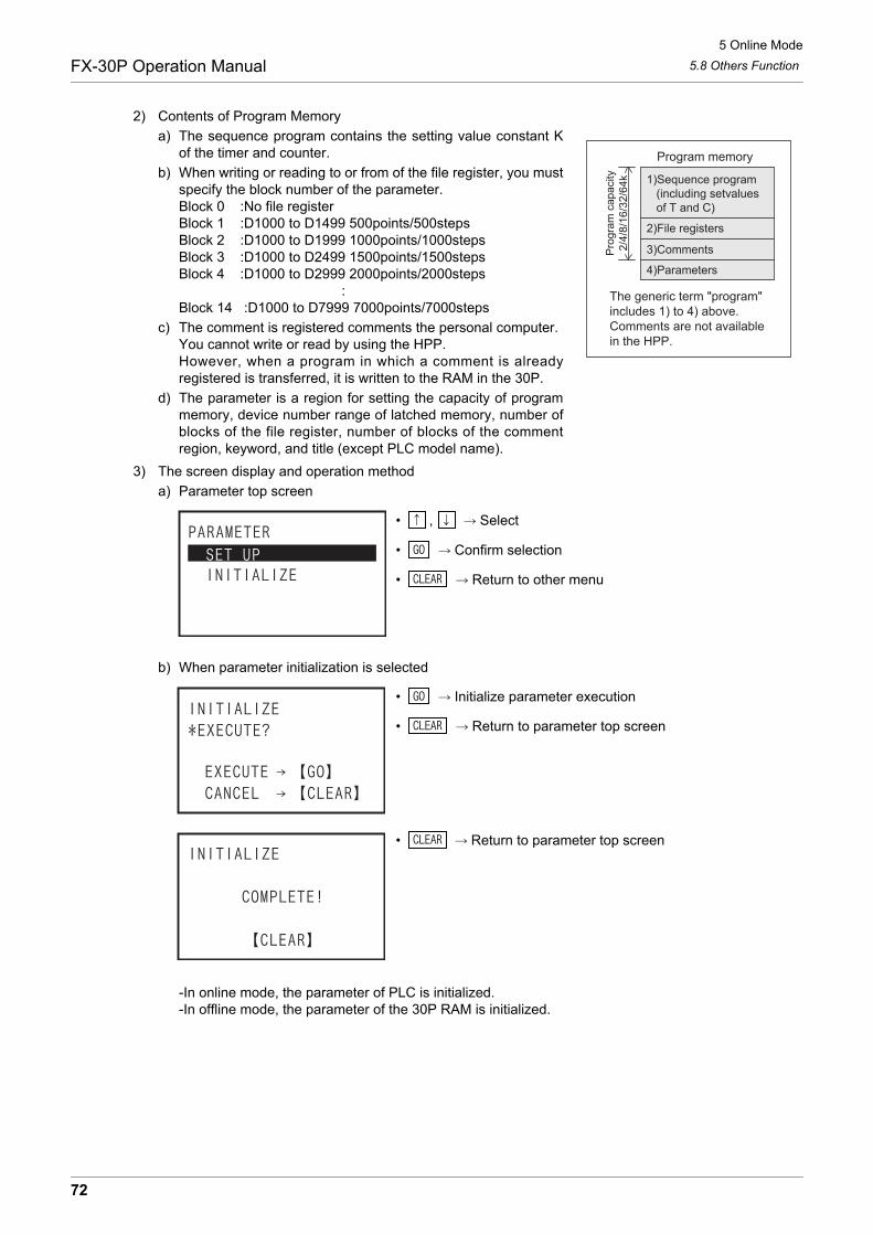
5 Online Mode
5.8 Others FunctionFX-30P Operation Manual
2) Contents of Program Memory
a) The sequence program contains the setting value constant Kof the timer and counter.
b) When writing or reading to or from of the file register, you mustspecify the block number of the parameter.Block 0 :No file registerBlock 1 :D1000 to D1499 500points/500stepsBlock 2 :D1000 to D1999 1000points/1000stepsBlock 3 :D1000 to D2499 1500points/1500stepsBlock 4 :D1000 to D2999 2000points/2000steps :Block 14 :D1000 to D7999 7000points/7000steps
c) The comment is registered comments the personal computer.You cannot write or read by using the HPP.However, when a program in which a comment is alreadyregistered is transferred, it is written to the RAM in the 30P.
d) The parameter is a region for setting the capacity of programmemory, device number range of latched memory, number ofblocks of the file register, number of blocks of the commentregion, keyword, and title (except PLC model name).
3) The screen display and operation method
a) Parameter top screen
• , Select
• Confirm selection
• Return to other menu
b) When parameter initialization is selected
• Initialize parameter execution
• Return to parameter top screen
• Return to parameter top screen
-In online mode, the parameter of PLC is initialized.-In offline mode, the parameter of the 30P RAM is initialized.
1)Sequence program (including setvalues of T and C)
2)File registers
3)Comments
4)Parameters
The generic term "program"includes 1) to 4) above.Comments are not available in the HPP.
Program memory
Pro
gram
cap
acity
2/4/
8/16
/32/
64k
72
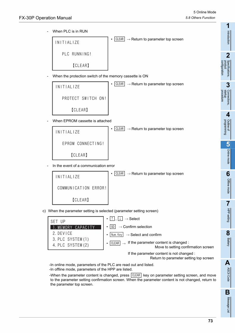
5 Online Mode
5.8 Others FunctionFX-30P Operation Manual
1
Introduction
2
Specifications,product configuration
3
Connections,
startup procedure
4
Outline of
programm
ing
5
Online m
ode
6
Offline m
ode
7
HP
P setting
8
Battery
A
AS
CII C
ode
B
Message List
- When PLC is in RUN
• Return to parameter top screen
- When the protection switch of the memory cassette is ON
• Return to parameter top screen
- When EPROM cassette is attached
• Return to parameter top screen
- In the event of a communication error
• Return to parameter top screen
c) When the parameter setting is selected (parameter setting screen)
• , Select
• Confirm selection
• Select and confirm
-In online mode, parameters of the PLC are read out and listed. -In offline mode, parameters of the HPP are listed.
-When the parameter content is changed, press key on parameter setting screen, and moveto the parameter setting confirmation screen. When the parameter content is not changed, return tothe parameter top screen.
• If the parameter content is changed : Move to setting confirmation screen
If the parameter content is not changed : Return to parameter setting top screen
73
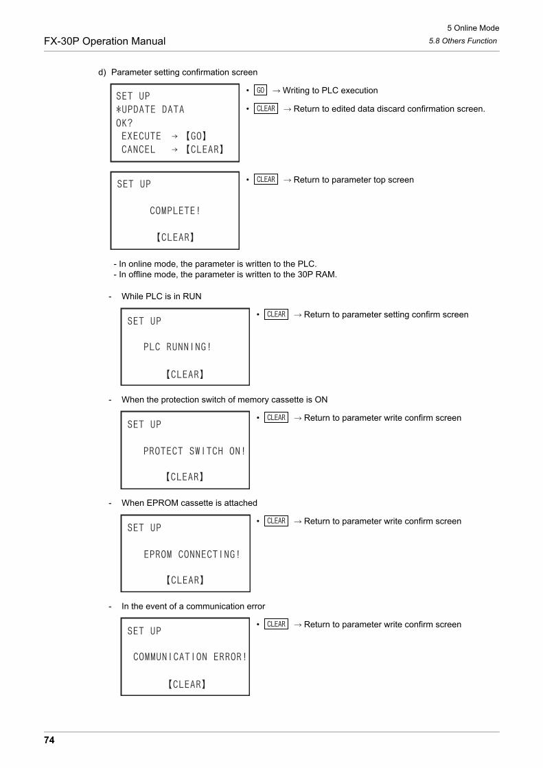
5 Online Mode
5.8 Others FunctionFX-30P Operation Manual
d) Parameter setting confirmation screen
• Writing to PLC execution
• Return to edited data discard confirmation screen.
• Return to parameter top screen
- In online mode, the parameter is written to the PLC. - In offline mode, the parameter is written to the 30P RAM.
- While PLC is in RUN
• Return to parameter setting confirm screen
- When the protection switch of memory cassette is ON
• Return to parameter write confirm screen
- When EPROM cassette is attached
• Return to parameter write confirm screen
- In the event of a communication error
• Return to parameter write confirm screen
74
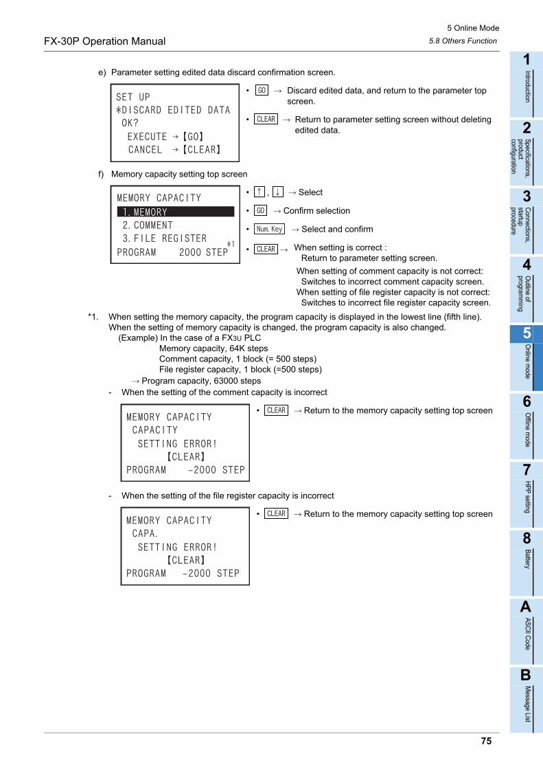
5 Online Mode
5.8 Others FunctionFX-30P Operation Manual
1
Introduction
2
Specifications,product configuration
3
Connections,
startup procedure
4
Outline of
programm
ing
5
Online m
ode
6
Offline m
ode
7
HP
P setting
8
Battery
A
AS
CII C
ode
B
Message List
e) Parameter setting edited data discard confirmation screen.
• Discard edited data, and return to the parameter top screen.
• Return to parameter setting screen without deleting edited data.
f) Memory capacity setting top screen
• , Select
• Confirm selection
• Select and confirm
*1. When setting the memory capacity, the program capacity is displayed in the lowest line (fifth line).When the setting of memory capacity is changed, the program capacity is also changed. (Example) In the case of a FX3U PLC Memory capacity, 64K steps Comment capacity, 1 block (= 500 steps) File register capacity, 1 block (=500 steps) Program capacity, 63000 steps- When the setting of the comment capacity is incorrect
• Return to the memory capacity setting top screen
- When the setting of the file register capacity is incorrect
• Return to the memory capacity setting top screen
• When setting is correct : Return to parameter setting screen.
When setting of comment capacity is not correct: Switches to incorrect comment capacity screen. When setting of file register capacity is not correct: Switches to incorrect file register capacity screen.
75
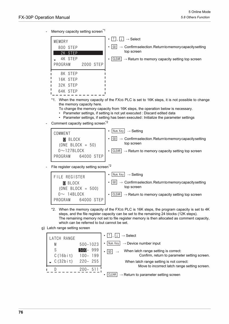
5 Online Mode
5.8 Others FunctionFX-30P Operation Manual
- Memory capacity setting screen*1
• , Select
• Confirm selection. Return to memory capacity setting top screen
• Return to memory capacity setting top screen
*1. When the memory capacity of the FX3S PLC is set to 16K steps, it is not possible to changethe memory capacity here.To change the memory capacity from 16K steps, the operation below is necessary.• Parameter settings, if setting is not yet executed : Discard edited data• Parameter settings, if setting has been executed: Initialize the parameter settings
- Comment capacity setting screen*2
• Setting
• Confirm selection. Return to memory capacity setting top screen
• Return to memory capacity setting top screen
- File register capacity setting screen*2
• Setting
• Confirm selection. Return to memory capacity setting top screen
• Return to memory capacity setting top screen
*2. When the memory capacity of the FX3S PLC is 16K steps, the program capacity is set to 4Ksteps, and the file register capacity can be set to the remaining 24 blocks (12K steps).The remaining memory not set to file register memory is then allocated as comment capacity,which can be referred to but cannot be set.
g) Latch range setting screen
• , Select
• Device number input
• Return to parameter setting screen
• When latch range setting is correct: Confirm, return to parameter setting screen.
When latch range setting is not correct: Move to incorrect latch range setting screen.
76
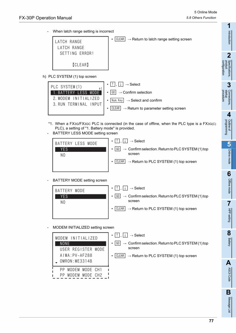
5 Online Mode
5.8 Others FunctionFX-30P Operation Manual
1
Introduction
2
Specifications,product configuration
3
Connections,
startup procedure
4
Outline of
programm
ing
5
Online m
ode
6
Offline m
ode
7
HP
P setting
8
Battery
A
AS
CII C
ode
B
Message List
- When latch range setting is incorrect
• Return to latch range setting screen
h) PLC SYSTEM (1) top screen
• , Select
• Confirm selection
• Select and confirm
• Return to parameter setting screen
*1. When a FX3G/FX3GC PLC is connected (in the case of offline, when the PLC type is a FX3G(C)
PLC), a setting of "1. Battery mode" is provided.- BATTERY LESS MODE setting screen
• , Select
• Confirm selection. Return to PLC SYSTEM (1) top screen
• Return to PLC SYSTEM (1) top screen
- BATTERY MODE setting screen
• , Select
• Confirm selection. Return to PLC SYSTEM (1) top screen
• Return to PLC SYSTEM (1) top screen
- MODEM INITIALIZED setting screen
• , Select
• Confirm selection. Return to PLC SYSTEM (1) top screen
• Return to PLC SYSTEM (1) top screen
77

5 Online Mode
5.8 Others FunctionFX-30P Operation Manual
i) RUN terminal input setting screen
• , Select
• Setting of input relay number
• Return to parameter list
- When the RUN terminal input is absent, select Absent by using key, and Confirm by pressing
key.
- When the RUN terminal input is present, select Present by key, set the input relay number by
keys, and decide by key.- When the input number of RUN terminal is wrong
• Return to RUN terminal input setting screen
j) PLC SYSTEM (2) top screen
• , Select
• Confirm selection
• Return to parameter setting screen
- Communication setting yes/no selection screen
• , Select
• Confirm selection, Move to next screen
• Return to PLC SYSTEM (2) top screen
• When Absent: Confirm, return to PLC SYSTEM (1) top screen.
When Present, and input number is correct: Confirm, return to PLC SYSTEM (1) top screen.
When Present, and input number is not correct: Switches to incorrect input number setting screen.
78

5 Online Mode
5.8 Others FunctionFX-30P Operation Manual
1
Introduction
2
Specifications,product configuration
3
Connections,
startup procedure
4
Outline of
programm
ing
5
Online m
ode
6
Offline m
ode
7
HP
P setting
8
Battery
A
AS
CII C
ode
B
Message List
- Communication setting top screen
• , Select
• Confirm selection, Move to next screen
• Return to communication setting yes/no select screen
- PROTOCOL setting screen
• , Select
• Confirm selection, Return to communication setting top screen
• Return to communication setting top screen
- DATA LENGTH setting screen
• , Select
• Confirm selection, Return to communication setting top screen
• Return to communication setting top screen
- PARITY setting screen
• , Select
• Confirm selection, Return to communication setting top screen
• Return to communication setting top screen
- STOP BIT setting screen
• , Select
• Confirm selection, Return to communication setting top screen
• Return to communication setting top screen
79
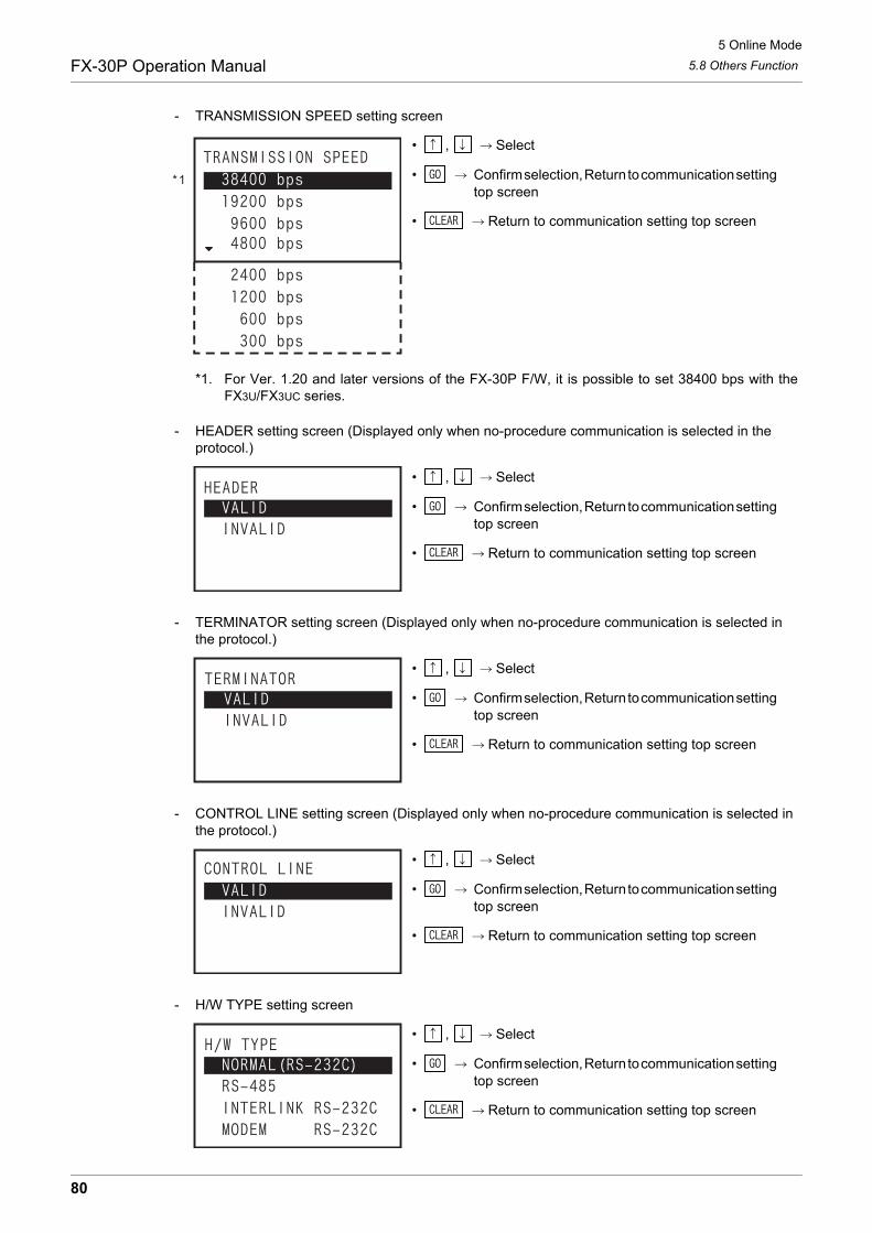
5 Online Mode
5.8 Others FunctionFX-30P Operation Manual
- TRANSMISSION SPEED setting screen
• , Select
• Confirm selection, Return to communication setting top screen
• Return to communication setting top screen
*1. For Ver. 1.20 and later versions of the FX-30P F/W, it is possible to set 38400 bps with theFX3U/FX3UC series.
- HEADER setting screen (Displayed only when no-procedure communication is selected in the protocol.)
• , Select
• Confirm selection, Return to communication setting top screen
• Return to communication setting top screen
- TERMINATOR setting screen (Displayed only when no-procedure communication is selected in the protocol.)
• , Select
• Confirm selection, Return to communication setting top screen
• Return to communication setting top screen
- CONTROL LINE setting screen (Displayed only when no-procedure communication is selected in the protocol.)
• , Select
• Confirm selection, Return to communication setting top screen
• Return to communication setting top screen
- H/W TYPE setting screen
• , Select
• Confirm selection, Return to communication setting top screen
• Return to communication setting top screen
*1
80
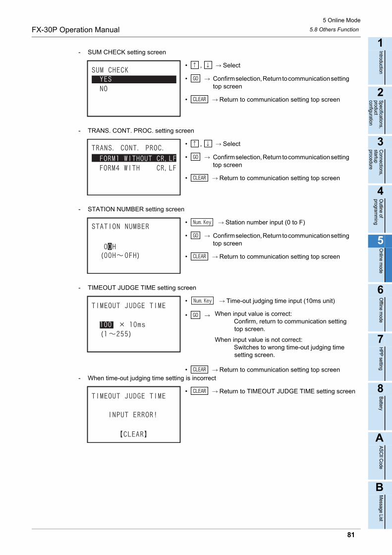
5 Online Mode
5.8 Others FunctionFX-30P Operation Manual
1
Introduction
2
Specifications,product configuration
3
Connections,
startup procedure
4
Outline of
programm
ing
5
Online m
ode
6
Offline m
ode
7
HP
P setting
8
Battery
A
AS
CII C
ode
B
Message List
- SUM CHECK setting screen
• , Select
• Confirm selection, Return to communication setting top screen
• Return to communication setting top screen
- TRANS. CONT. PROC. setting screen
• , Select
• Confirm selection, Return to communication setting top screen
• Return to communication setting top screen
- STATION NUMBER setting screen
• Station number input (0 to F)
• Confirm selection, Return to communication setting top screen
• Return to communication setting top screen
- TIMEOUT JUDGE TIME setting screen
• Time-out judging time input (10ms unit)
• Return to communication setting top screen- When time-out judging time setting is incorrect
• Return to TIMEOUT JUDGE TIME setting screen
• When input value is correct: Confirm, return to communication setting
top screen.
When input value is not correct: Switches to wrong time-out judging time
setting screen.
81
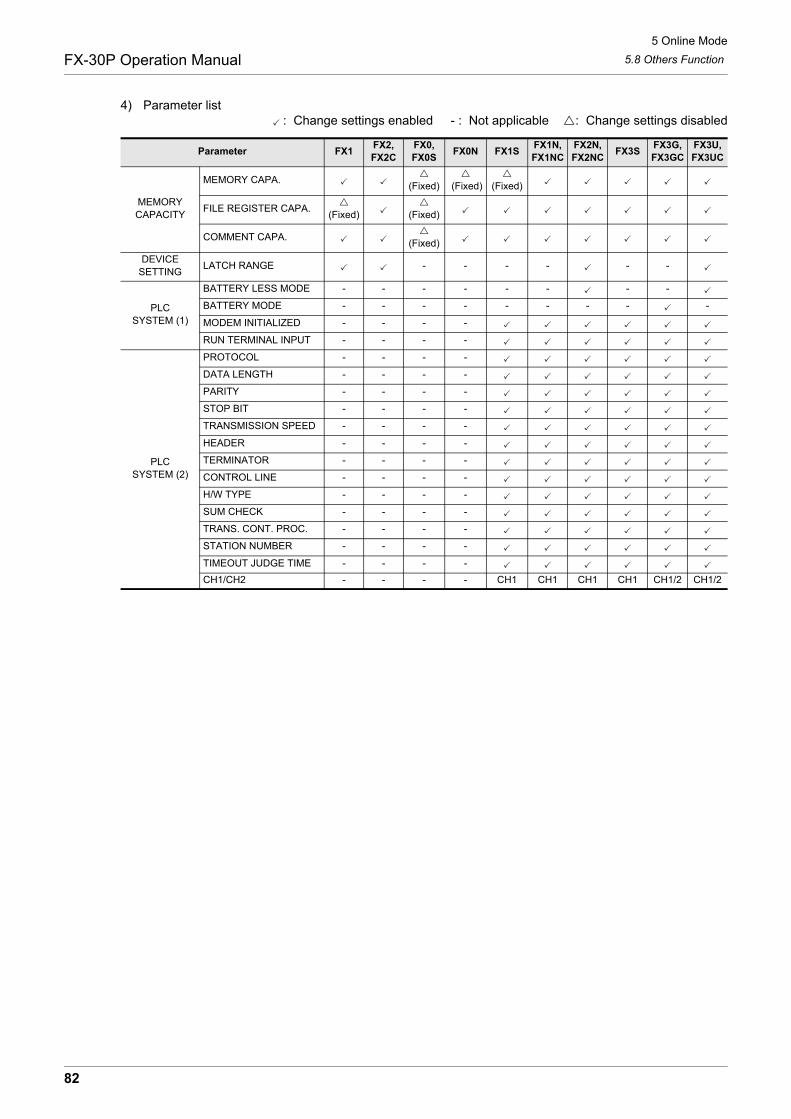
5 Online Mode
5.8 Others FunctionFX-30P Operation Manual
4) Parameter list: Change settings enabled - : Not applicable : Change settings disabled
Parameter FX1FX2,FX2C
FX0,FX0S
FX0N FX1SFX1N,FX1NC
FX2N,FX2NC
FX3SFX3G,FX3GC
FX3U,FX3UC
MEMORY CAPACITY
MEMORY CAPA.
(Fixed)
(Fixed)
(Fixed)
FILE REGISTER CAPA.
(Fixed)
(Fixed)
COMMENT CAPA.
(Fixed)
DEVICESETTING
LATCH RANGE - - - - - -
PLC SYSTEM (1)
BATTERY LESS MODE - - - - - - - -
BATTERY MODE - - - - - - - - -
MODEM INITIALIZED - - - -
RUN TERMINAL INPUT - - - -
PLC SYSTEM (2)
PROTOCOL - - - -
DATA LENGTH - - - -
PARITY - - - -
STOP BIT - - - -
TRANSMISSION SPEED - - - -
HEADER - - - -
TERMINATOR - - - -
CONTROL LINE - - - -
H/W TYPE - - - -
SUM CHECK - - - -
TRANS. CONT. PROC. - - - -
STATION NUMBER - - - -
TIMEOUT JUDGE TIME - - - -
CH1/CH2 - - - - CH1 CH1 CH1 CH1 CH1/2 CH1/2
82
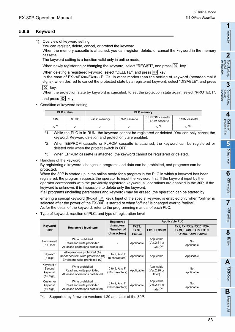
5 Online Mode
5.8 Others FunctionFX-30P Operation Manual
1
Introduction
2
Specifications,product configuration
3
Connections,
startup procedure
4
Outline of
programm
ing
5
Online m
ode
6
Offline m
ode
7
HP
P setting
8
Battery
A
AS
CII C
ode
B
Message List
5.8.6 Keyword
1) Overview of keyword settingYou can register, delete, cancel, or protect the keyword.When the memory cassette is attached, you can register, delete, or cancel the keyword in the memorycassette.The keyword setting is a function valid only in online mode.
When newly registering or changing the keyword, select "REGIST", and press key.
When deleting a registered keyword, select "DELETE", and press key.In the case of FX3G/FX3U/FX3UC PLCs, in other modes than the setting of keyword (hexadecimal 8digits), when desired to cancel the protected state by a registered keyword, select "DISABLE", and press
key.When the protection state by keyword is canceled, to set the protection state again, select "PROTECT",
and press key.
• Condition of keyword setting
*1. While the PLC is in RUN, the keyword cannot be registered or deleted. You can only cancel thekeyword. Keyword deletion and protect only are enabled.
*2. When EEPROM cassette or FLROM cassette is attached, the keyword can be registered ordeleted only when the protect switch is OFF.
*3. When EPROM cassette is attached, the keyword cannot be registered or deleted.
• Handling of the keywordBy registering a keyword, changes in programs and data can be prohibited, and programs can be protected.When the 30P is started up in the online mode for a program in the PLC in which a keyword has been registered, the program requests the operator to input the keyword first. If the keyword input by the operator corresponds with the previously registered keyword, all operations are enabled in the 30P. If the keyword is unknown, it is impossible to delete only the keyword. If all programs (including parameters and keyword) may be erased, the operation can be started by
entering a special keyword (8-digit key). Input of the special keyword is enabled only when "online" is selected after the power of the FX-30P is started or when "offline" is changed over to "online".As for the detail of the keyword, refer to the programming manual of each PLC.
• Type of keyword, reaction of PLC, and type of registration level
*4. Supported by firmware versions 1.20 and later of the 30P.
PLC status PLC memory
RUN STOP Built in memory RAM cassetteEEPROM cassetteFLROM cassette
EPROM cassette
*1 *2 *3
Keyword type
Registered level type
Registered characters
(Number of characters)
Applicable PLC
FX3S,FX3G,FX3GC
FX3U, FX3UCFX1, FX(FX2), FX2C, FX0, FX0S, FX0N, FX1S, FX1N,
FX1NC, FX2N, FX2NC
Permanent PLC lock
Write prohibitedRead and write prohibited
All online operations prohibited- Applicable
Applicable(Ver.2.61 or
later)*4
Not applicable
Keyword(8 digit)
All operations prohibited (A)Read/Incorrect write protection (B)
Erroneous write prohibited (C)
0 to 9, A to F(8 characters)
Applicable Applicable Applicable
Keyword + Second keyword(16 digit)
Write prohibitedRead and write prohibited
All online operations prohibited
0 to 9, A to F(16 characters)
ApplicableApplicable
(Ver.2.20 or later)
Not applicable
Customer keyword(16 digit)
Write prohibitedRead and write prohibited
All online operations prohibited
0 to 9, A to F(16 characters)
Applicable
Applicable(Ver.2.61 or
later)*4
Not applicable
83
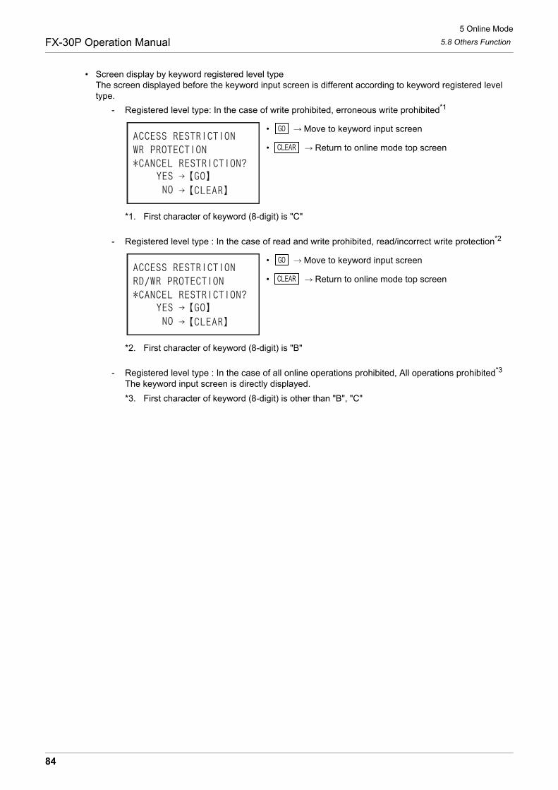
5 Online Mode
5.8 Others FunctionFX-30P Operation Manual
• Screen display by keyword registered level typeThe screen displayed before the keyword input screen is different according to keyword registered level type.
- Registered level type: In the case of write prohibited, erroneous write prohibited*1
• Move to keyword input screen
• Return to online mode top screen
*1. First character of keyword (8-digit) is "C"
- Registered level type : In the case of read and write prohibited, read/incorrect write protection*2
• Move to keyword input screen
• Return to online mode top screen
*2. First character of keyword (8-digit) is "B"
- Registered level type : In the case of all online operations prohibited, All operations prohibited*3
The keyword input screen is directly displayed.
*3. First character of keyword (8-digit) is other than "B", "C"
84
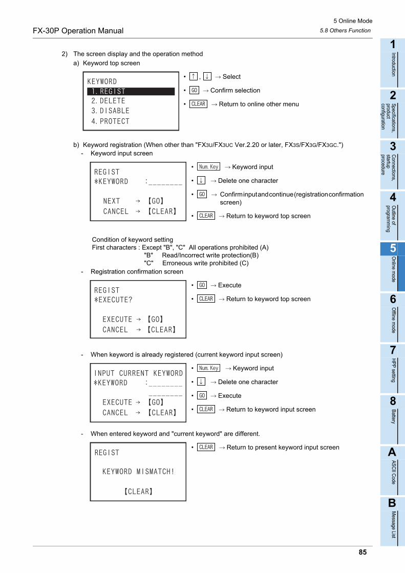
5 Online Mode
5.8 Others FunctionFX-30P Operation Manual
1
Introduction
2
Specifications,product configuration
3
Connections,
startup procedure
4
Outline of
programm
ing
5
Online m
ode
6
Offline m
ode
7
HP
P setting
8
Battery
A
AS
CII C
ode
B
Message List
2) The screen display and the operation method
a) Keyword top screen
• , Select
• Confirm selection
• Return to online other menu
b) Keyword registration (When other than "FX3U/FX3UC Ver.2.20 or later, FX3S/FX3G/FX3GC.")- Keyword input screen
• Keyword input
• Delete one character
• Confirm input and continue (registration confirmation screen)
• Return to keyword top screen
Condition of keyword setting First characters : Except "B", "C" All operations prohibited (A) "B" Read/Incorrect write protection(B) "C" Erroneous write prohibited (C)
- Registration confirmation screen
• Execute
• Return to keyword top screen
- When keyword is already registered (current keyword input screen)
• Keyword input
• Delete one character
• Execute
• Return to keyword input screen
- When entered keyword and "current keyword" are different.
• Return to present keyword input screen
85
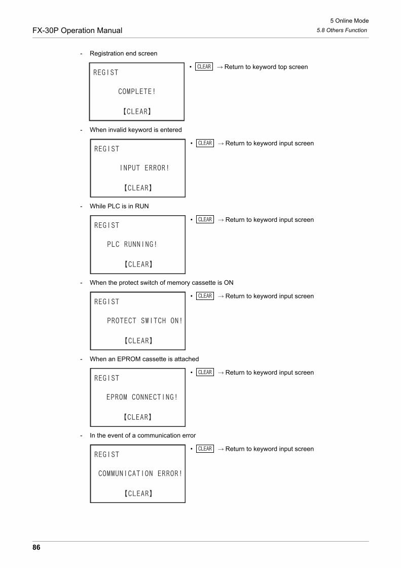
5 Online Mode
5.8 Others FunctionFX-30P Operation Manual
- Registration end screen
• Return to keyword top screen
- When invalid keyword is entered
• Return to keyword input screen
- While PLC is in RUN
• Return to keyword input screen
- When the protect switch of memory cassette is ON
• Return to keyword input screen
- When an EPROM cassette is attached
• Return to keyword input screen
- In the event of a communication error
• Return to keyword input screen
86

5 Online Mode
5.8 Others FunctionFX-30P Operation Manual
1
Introduction
2
Specifications,product configuration
3
Connections,
startup procedure
4
Outline of
programm
ing
5
Online m
ode
6
Offline m
ode
7
HP
P setting
8
Battery
A
AS
CII C
ode
B
Message List
c) Keyword registration (FX3U/FX3UC Ver.2.20 up to Ver.2.61)
- Keyword input screen
• Keyword input
• Delete one character
• Confirm input
• Return to keyword top screen
"Keyword + second keyword" is set in hexadecimal 16 digits from 0 to F.- Protect level selection screen (this screen is not displayed by input of "keyword" only).
• , Protect level select
• Confirm selection
• Return to keyword top screen
- Registration confirmation screen
• Execute
• Return to keyword top screen
- When a keyword is already registered (current keyword input screen)
• Keyword input
• Delete one character
• Confirm input
• Return to keyword input screen
- When entered keyword and "current keyword" are different.
• Return to present keyword input screen
87
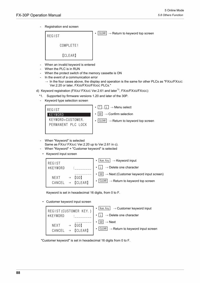
5 Online Mode
5.8 Others FunctionFX-30P Operation Manual
- Registration end screen
• Return to keyword top screen
- When an invalid keyword is entered- When the PLC is in RUN- When the protect switch of the memory cassette is ON- In the event of a communication error In the four cases above, the display and operation is the same for other PLCs as "FX3U/FX3UC Ver.2.20 or later, FX3S/FX3G/FX3GC PLCs."
d) Keyword registration (FX3U/ FX3UC Ver.2.61 and later*1, FX3S/FX3G/FX3GC)
*1. Supported by firmware versions 1.20 and later of the 30P.
- Keyword type selection screen
• , Menu select
• Confirm selection
• Return to keyword top screen
- When "Keyword" is selectedSame as FX3U/ FX3UC Ver.2.20 up to Ver.2.61 in c).
- When "Keyword" + "Customer keyword" is selected
• Keyword input screen
• Keyword input
• Delete one character
• Next (Customer keyword input screen)
• Return to keyword top screen
Keyword is set in hexadecimal 16 digits, from 0 to F.
• Customer keyword input screen
• Customer keyword input
• Delete one character
• Next
• Return to keyword input screen
"Customer keyword" is set in hexadecimal 16 digits from 0 to F.
88
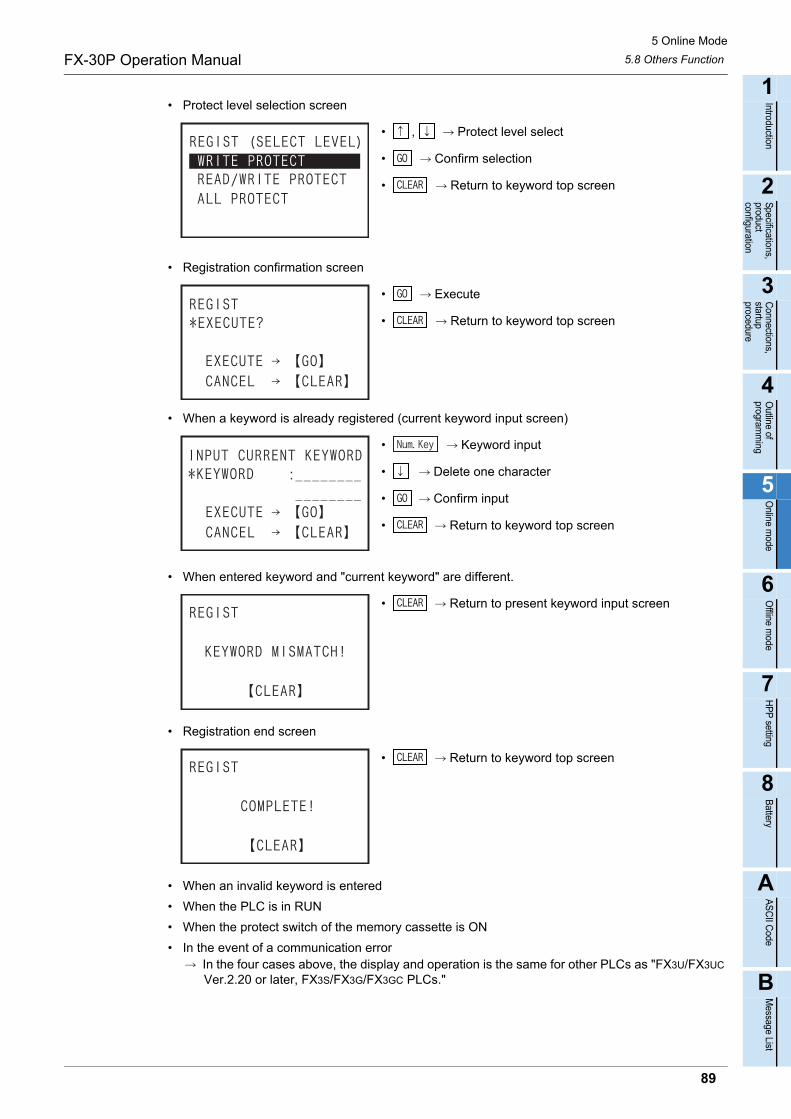
5 Online Mode
5.8 Others FunctionFX-30P Operation Manual
1
Introduction
2
Specifications,product configuration
3
Connections,
startup procedure
4
Outline of
programm
ing
5
Online m
ode
6
Offline m
ode
7
HP
P setting
8
Battery
A
AS
CII C
ode
B
Message List
• Protect level selection screen
• , Protect level select
• Confirm selection
• Return to keyword top screen
• Registration confirmation screen
• Execute
• Return to keyword top screen
• When a keyword is already registered (current keyword input screen)
• Keyword input
• Delete one character
• Confirm input
• Return to keyword top screen
• When entered keyword and "current keyword" are different.
• Return to present keyword input screen
• Registration end screen
• Return to keyword top screen
• When an invalid keyword is entered
• When the PLC is in RUN
• When the protect switch of the memory cassette is ON
• In the event of a communication error In the four cases above, the display and operation is the same for other PLCs as "FX3U/FX3UC
Ver.2.20 or later, FX3S/FX3G/FX3GC PLCs."
89
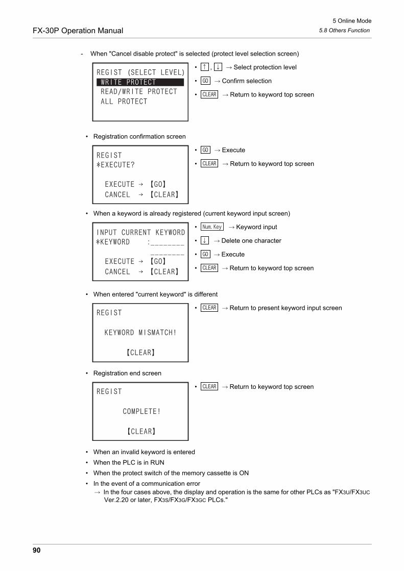
5 Online Mode
5.8 Others FunctionFX-30P Operation Manual
- When "Cancel disable protect" is selected (protect level selection screen)
• , Select protection level
• Confirm selection
• Return to keyword top screen
• Registration confirmation screen
• Execute
• Return to keyword top screen
• When a keyword is already registered (current keyword input screen)
• Keyword input
• Delete one character
• Execute
• Return to keyword top screen
• When entered "current keyword" is different
• Return to present keyword input screen
• Registration end screen
• Return to keyword top screen
• When an invalid keyword is entered
• When the PLC is in RUN
• When the protect switch of the memory cassette is ON
• In the event of a communication error In the four cases above, the display and operation is the same for other PLCs as "FX3U/FX3UC
Ver.2.20 or later, FX3S/FX3G/FX3GC PLCs."
90

5 Online Mode
5.8 Others FunctionFX-30P Operation Manual
1
Introduction
2
Specifications,product configuration
3
Connections,
startup procedure
4
Outline of
programm
ing
5
Online m
ode
6
Offline m
ode
7
HP
P setting
8
Battery
A
AS
CII C
ode
B
Message List
e) Keyword deletion screen- When a keyword is not registered
• Return to keyword top screen
- Keyword input screen
• When other than "FX3U/FX3UC Ver.2.20 or later, FX3S/FX3G/FX3GC."
• Keyword input
• Delete one character
• Next
• Return to keyword top screen
When the "Keyword" is registered, it is entered in hexadecimal 8 digits from 0 to F.
• In the case of "FX3U/FX3UC Ver.2.20 or later, FX3S/FX3G/FX3GC."
• Keyword input
• Delete one character
• Next
• Return to keyword top screen
When the "Keyword" is registered, it is entered in hexadecimal from 0 to F.- Delete confirmation screen
• Execute
• Return to keyword top screen
- When the entered keyword and "current keyword" are different.
• Return to keyword input screen
91

5 Online Mode
5.8 Others FunctionFX-30P Operation Manual
- Delete end screen
• Return to keyword top screen
- When an invalid keyword is entered
• Return to keyword input screen
- When the PLC is in RUN
• Return to keyword input screen
- When the protect switch of the memory cassette is ON
• Return to keyword input screen
- When an EPROM cassette is attached
• Return to keyword input screen
- In the event of a communication error
• Return to keyword input screen
92
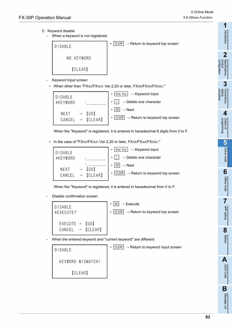
5 Online Mode
5.8 Others FunctionFX-30P Operation Manual
1
Introduction
2
Specifications,product configuration
3
Connections,
startup procedure
4
Outline of
programm
ing
5
Online m
ode
6
Offline m
ode
7
HP
P setting
8
Battery
A
AS
CII C
ode
B
Message List
f) Keyword disable- When a keyword is not registered
• Return to keyword top screen
- Keyword input screen
• When other than "FX3U/FX3UC Ver.2.20 or later, FX3S/FX3G/FX3GC."
• Keyword input
• Delete one character
• Next
• Return to keyword top screen
When the "Keyword" is registered, it is entered in hexadecimal 8 digits from 0 to F.
• In the case of "FX3U/FX3UC Ver.2.20 or later, FX3S/FX3G/FX3GC."
• Keyword input
• Delete one character
• Next
• Return to keyword top screen
When the "Keyword" is registered, it is entered in hexadecimal from 0 to F.
- Disable confirmation screen
• Execute
• Return to keyword top screen
- When the entered keyword and "current keyword" are different.
• Return to keyword input screen
93

5 Online Mode
5.8 Others FunctionFX-30P Operation Manual
- Disable end screen
• Return to keyword top screen
- When an invalid keyword is entered
• Return to keyword input screen
- In the event of a communication error
• Return to keyword input screen
g) Keyword protect- When a keyword is not registered
• Return to keyword top screen
- Protect confirmation screen
• Execute
• Return to keyword top screen
94
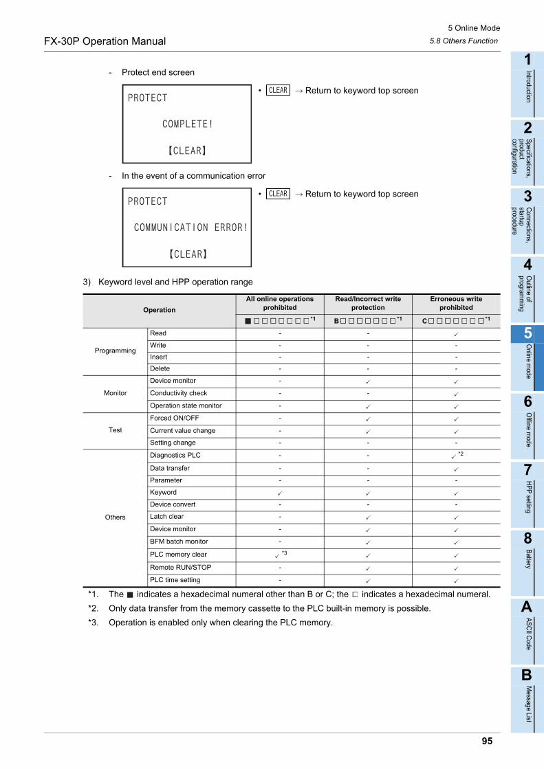
5 Online Mode
5.8 Others FunctionFX-30P Operation Manual
1
Introduction
2
Specifications,product configuration
3
Connections,
startup procedure
4
Outline of
programm
ing
5
Online m
ode
6
Offline m
ode
7
HP
P setting
8
Battery
A
AS
CII C
ode
B
Message List
- Protect end screen
• Return to keyword top screen
- In the event of a communication error
• Return to keyword top screen
3) Keyword level and HPP operation range
*1. The indicates a hexadecimal numeral other than B or C; the indicates a hexadecimal numeral.
*2. Only data transfer from the memory cassette to the PLC built-in memory is possible.
*3. Operation is enabled only when clearing the PLC memory.
Operation
All online operations prohibited
Read/Incorrect write protection
Erroneous write prohibited
*1 B *1 C *1
Programming
Read - -
Write - - -
Insert - - -
Delete - - -
Monitor
Device monitor -
Conductivity check - -
Operation state monitor -
Test
Forced ON/OFF -
Current value change -
Setting change - - -
Others
Diagnostics PLC - - *2
Data transfer - -
Parameter - - -
Keyword
Device convert - - -
Latch clear -
Device monitor -
BFM batch monitor -
PLC memory clear *3
Remote RUN/STOP -
PLC time setting -
95
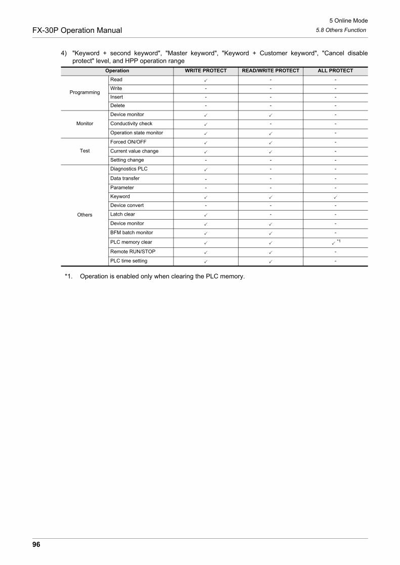
5 Online Mode
5.8 Others FunctionFX-30P Operation Manual
4) "Keyword + second keyword", "Master keyword", "Keyword + Customer keyword", "Cancel disableprotect" level, and HPP operation range
*1. Operation is enabled only when clearing the PLC memory.
Operation WRITE PROTECT READ/WRITE PROTECT ALL PROTECT
Programming
Read - -
Write - - -
Insert - - -
Delete - - -
Monitor
Device monitor -
Conductivity check - -
Operation state monitor -
Test
Forced ON/OFF -
Current value change -
Setting change - - -
Others
Diagnostics PLC - -
Data transfer - - -
Parameter - - -
Keyword
Device convert - - -
Latch clear - -
Device monitor -
BFM batch monitor -
PLC memory clear *1
Remote RUN/STOP -
PLC time setting -
96
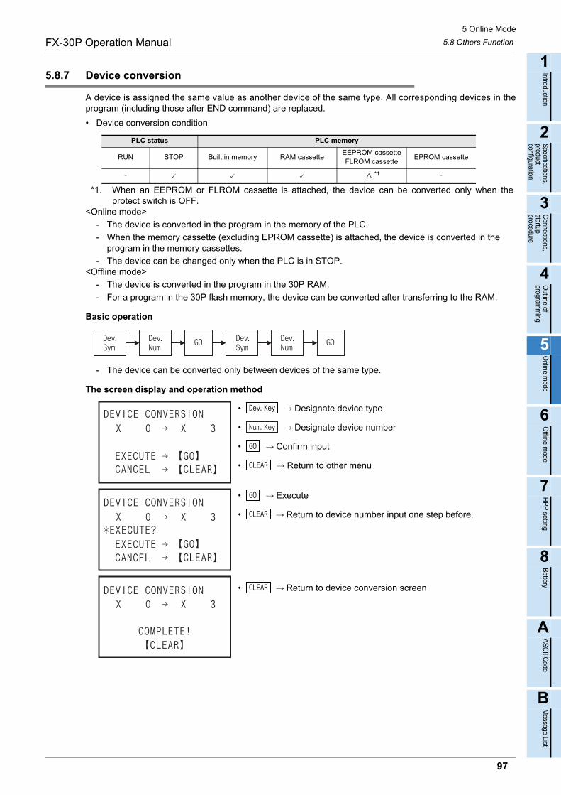
5 Online Mode
5.8 Others FunctionFX-30P Operation Manual
1
Introduction
2
Specifications,product configuration
3
Connections,
startup procedure
4
Outline of
programm
ing
5
Online m
ode
6
Offline m
ode
7
HP
P setting
8
Battery
A
AS
CII C
ode
B
Message List
5.8.7 Device conversion
A device is assigned the same value as another device of the same type. All corresponding devices in theprogram (including those after END command) are replaced.
• Device conversion condition
*1. When an EEPROM or FLROM cassette is attached, the device can be converted only when theprotect switch is OFF.
<Online mode>
- The device is converted in the program in the memory of the PLC.
- When the memory cassette (excluding EPROM cassette) is attached, the device is converted in the program in the memory cassettes.
- The device can be changed only when the PLC is in STOP.<Offline mode>
- The device is converted in the program in the 30P RAM.
- For a program in the 30P flash memory, the device can be converted after transferring to the RAM.
Basic operation
- The device can be converted only between devices of the same type.
The screen display and operation method
• Designate device type
• Designate device number
• Confirm input
• Return to other menu
• Execute
• Return to device number input one step before.
• Return to device conversion screen
PLC status PLC memory
RUN STOP Built in memory RAM cassetteEEPROM cassetteFLROM cassette
EPROM cassette
- *1 -
97
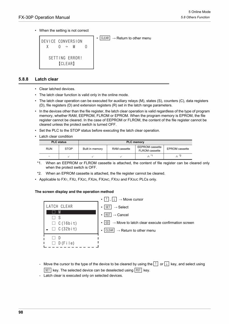
5 Online Mode
5.8 Others FunctionFX-30P Operation Manual
• When the setting is not correct
• Return to other menu
5.8.8 Latch clear
• Clear latched devices.
• The latch clear function is valid only in the online mode.
• The latch clear operation can be executed for auxiliary relays (M), states (S), counters (C), data registers (D), file registers (D) and extension registers (R) set in the latch range parameters.
• In the devices other than the file register, the latch clear operation is valid regardless of the type of program memory, whether RAM, EEPROM, FLROM or EPROM. When the program memory is EPROM, the file register cannot be cleared. In the case of EEPROM or FLROM, the content of the file register cannot be cleared unless the protect switch is turned OFF.
• Set the PLC to the STOP status before executing the latch clear operation.
• Latch clear condition
*1. When an EEPROM or FLROM cassette is attached, the content of file register can be cleared onlywhen the protect switch is OFF.
*2. When an EPROM cassette is attached, the file register cannot be cleared.
• Applicable to FX1, FX2, FX2C, FX2N, FX2NC, FX3U and FX3UC PLCs only.
The screen display and the operation method
• , Move cursor
• Select
• Cancel
• Move to latch clear execute confirmation screen
• Return to other menu
- Move the cursor to the type of the device to be cleared by using the or key, and select using
key. The selected device can be deselected using key.
- Latch clear is executed only on selected devices.
PLC status PLC memory
RUN STOP Built in memory RAM cassetteEEPROM cassetteFLROM cassette
EPROM cassette
- *1 *2
98

5 Online Mode
5.8 Others FunctionFX-30P Operation Manual
1
Introduction
2
Specifications,product configuration
3
Connections,
startup procedure
4
Outline of
programm
ing
5
Online m
ode
6
Offline m
ode
7
HP
P setting
8
Battery
A
AS
CII C
ode
B
Message List
• Check screen
• , Select
• Confirm selection
• Return to other menu
• Latch clear execution confirmation screen
• Latch clear execute
• Return to latch clear selection screen
• Latch clear end screen
• Return to other menu
• In the event of a communication error
• Return to other menu
99

5 Online Mode
5.8 Others FunctionFX-30P Operation Manual
5.8.9 Device batch monitoring
One type of device is selected, and listed.
• Condition of device batch monitor
- One type of device is batch monitored out of the X, Y, M, S, T, C, D, R devices of the PLC.
- Device test is also enabled on the device batch monitor screen.
- The device batch monitor function is valid only in online mode.
The screen display and operation method
1) Word device (D, R)
PLC status PLC memory
RUN STOP Built in memory RAM cassetteEEPROM cassetteFLROM cassette
EPROM cassette
16 bits, hexadecimal notation is selected.
32 bits, hexadecimal notation is selected.
16 bits, decimal notation is selected.
32 bits, decimal notation is selected.
Real number is selected. ASCII is selected.
100

5 Online Mode
5.8 Others FunctionFX-30P Operation Manual
1
Introduction
2
Specifications,product configuration
3
Connections,
startup procedure
4
Outline of
programm
ing
5
Online m
ode
6
Offline m
ode
7
HP
P setting
8
Battery
A
AS
CII C
ode
B
Message List
a) List display
Select "Device batch monitor", press key, enter the device symbol (D, R) and device number,
press key to confirm, and display list. If not in "Monitor mode," press key and select themonitor mode.
Basic operation
- To change between decimal and hexadecimal notation, press key.
- To change between 16 bits and 32 bits, press key.
- To change to ASCII display, press key.
- To change to real number display, press key.
b) Current value change
If not in "Test mode," press key and select the test mode. Move the cursor to the line to be
changed, press key, select decimal or hexadecimal notation using key, and enter the value
using keys.
Basic operation
2) Timer, Counter (T, C)
a) List display
Select "Device batch monitor", press key, enter the device symbol (T, C) and device number,
press key to confirm, and display list. If not in "Monitor mode," press key and select themonitor mode.
Basic operation
- To change between decimal and hexadecimal notation, press key.
- To change between 16 bits and 32 bits, press key.
T or 16 bits C, decimal notation is selected.
32 bits C, decimal notation is selected.
T or 16 bits C, hexadecimal notation is selected.
32 bits C, hexadecimal notation is selected.
101
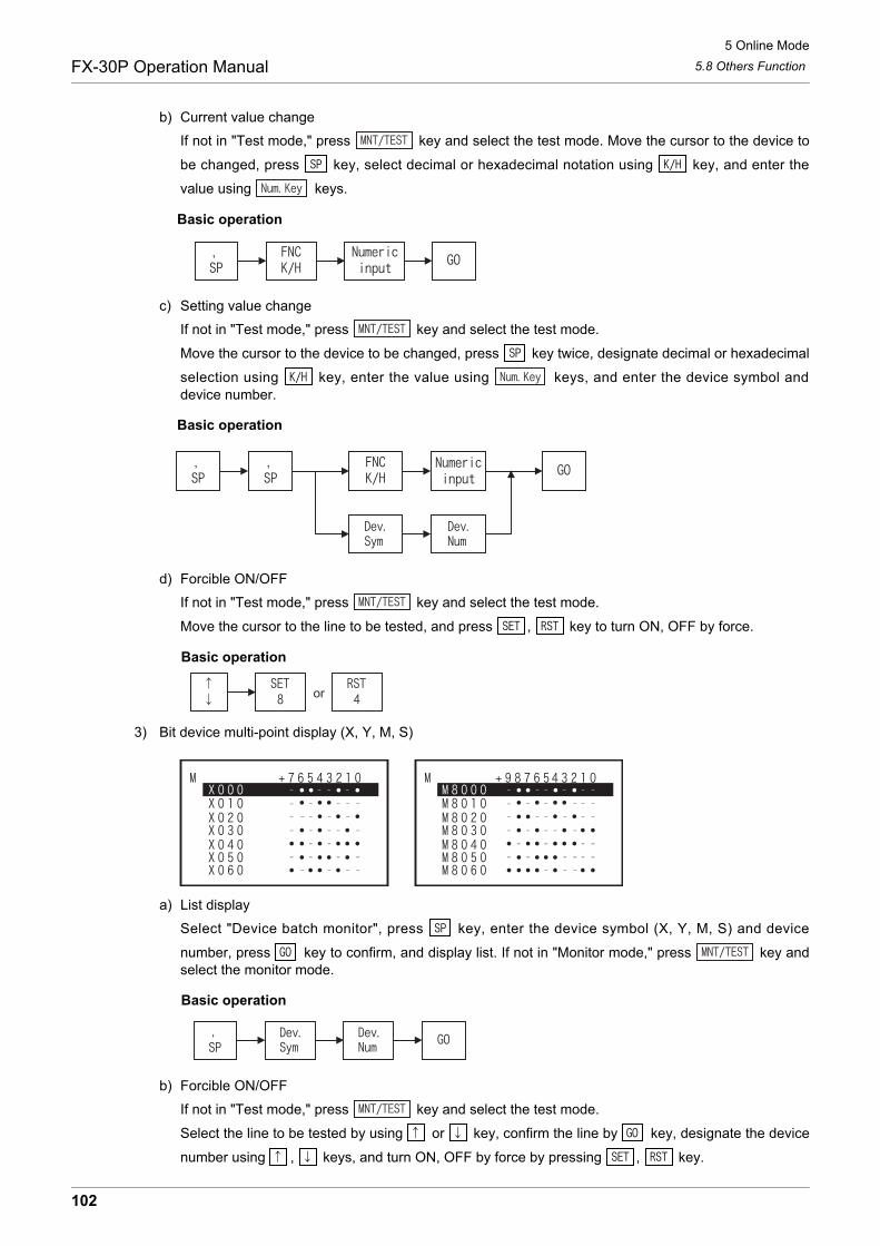
5 Online Mode
5.8 Others FunctionFX-30P Operation Manual
b) Current value change
If not in "Test mode," press key and select the test mode. Move the cursor to the device to
be changed, press key, select decimal or hexadecimal notation using key, and enter the
value using keys.
Basic operation
c) Setting value change
If not in "Test mode," press key and select the test mode.
Move the cursor to the device to be changed, press key twice, designate decimal or hexadecimal
selection using key, enter the value using keys, and enter the device symbol anddevice number.
Basic operation
d) Forcible ON/OFF
If not in "Test mode," press key and select the test mode.
Move the cursor to the line to be tested, and press , key to turn ON, OFF by force.
Basic operation
3) Bit device multi-point display (X, Y, M, S)
a) List display
Select "Device batch monitor", press key, enter the device symbol (X, Y, M, S) and device
number, press key to confirm, and display list. If not in "Monitor mode," press key andselect the monitor mode.
Basic operation
b) Forcible ON/OFF
If not in "Test mode," press key and select the test mode.
Select the line to be tested by using or key, confirm the line by key, designate the device
number using , keys, and turn ON, OFF by force by pressing , key.
or
102

5 Online Mode
5.8 Others FunctionFX-30P Operation Manual
1
Introduction
2
Specifications,product configuration
3
Connections,
startup procedure
4
Outline of
programm
ing
5
Online m
ode
6
Offline m
ode
7
HP
P setting
8
Battery
A
AS
CII C
ode
B
Message List
Basic operation
Operation example When changing M2 from OFF to ON,
Display example Key operation
Step 7) Move the cursor to the position of M2.
1)
2)
3)
4)
5)
6)
7)
Step 6)
103

5 Online Mode
5.8 Others FunctionFX-30P Operation Manual
5.8.10 BFM batch monitor
The special function block is designated, and the buffer memory (BFM) is listed and monitored.
• Condition of buffer memory (BFM) batch monitoring
- The special function block is designated, and the buffer memory (BFM) is listed.
- You can switch between decimal/hexadecimal notation, 16 bits/32 bits, real number, and ASCII display.
- The buffer memory (BFM) batch monitoring function is valid in online mode only.
The screen display and operation method
• , Select
• Return to other menu
The method for changing the display is same as in Subsection 5.8.9, Device batch monitor worddevice (D, R).
1) List displayBasic operation
2) Set value changeBasic operation
- FX1N, FX1NC, FX2N, FX2NC, FX3G, FX3GC, FX3U, FX3UC only can be monitored.
- FX0N-3A, FX2N-2AD, FX2N-2DA cannot be monitored.
PLC status PLC memory
RUN STOP Built in memory RAM cassetteEEPROM cassetteFLROM cassette
EPROM cassette
BFM No.(#0~#32767) Set value
Unit No.(U0~U7)
104
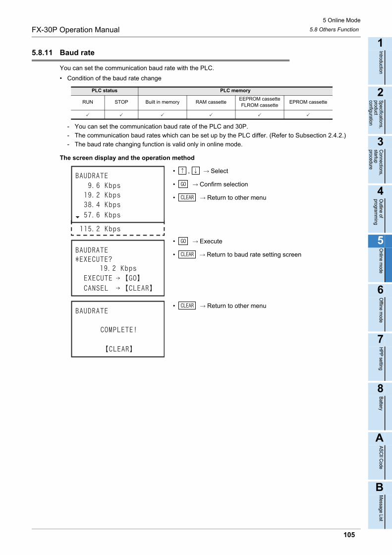
5 Online Mode
5.8 Others FunctionFX-30P Operation Manual
1
Introduction
2
Specifications,product configuration
3
Connections,
startup procedure
4
Outline of
programm
ing
5
Online m
ode
6
Offline m
ode
7
HP
P setting
8
Battery
A
AS
CII C
ode
B
Message List
5.8.11 Baud rate
You can set the communication baud rate with the PLC.
• Condition of the baud rate change
- You can set the communication baud rate of the PLC and 30P.
- The communication baud rates which can be set up by the PLC differ. (Refer to Subsection 2.4.2.)
- The baud rate changing function is valid only in online mode.
The screen display and the operation method
• , Select
• Confirm selection
• Return to other menu
• Execute
• Return to baud rate setting screen
• Return to other menu
PLC status PLC memory
RUN STOP Built in memory RAM cassetteEEPROM cassetteFLROM cassette
EPROM cassette
105
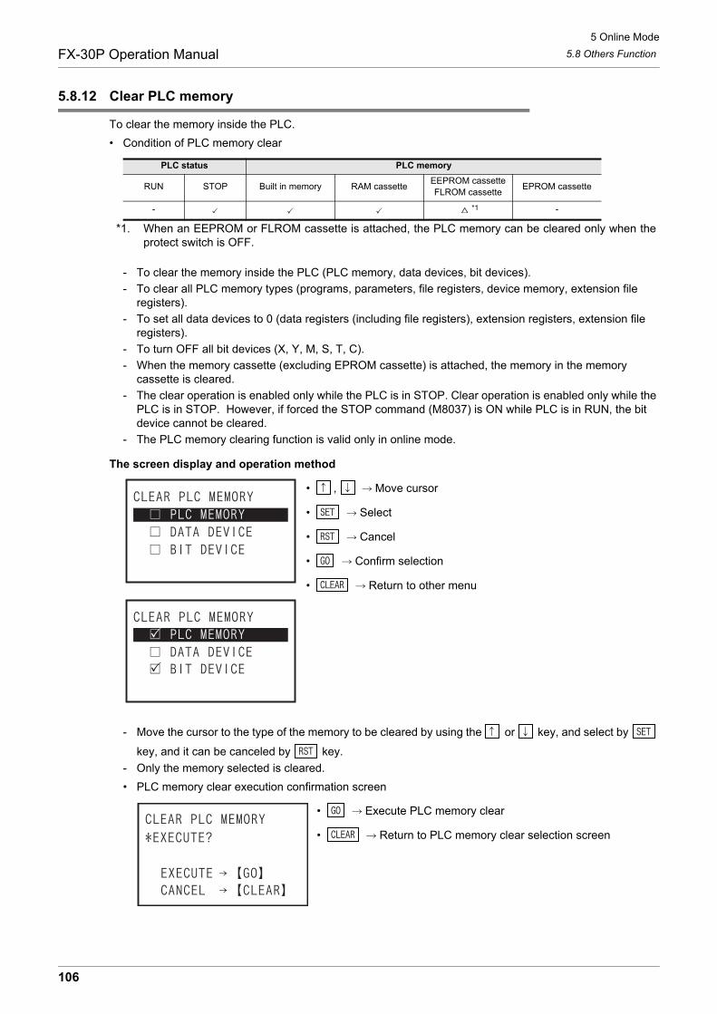
5 Online Mode
5.8 Others FunctionFX-30P Operation Manual
5.8.12 Clear PLC memory
To clear the memory inside the PLC.
• Condition of PLC memory clear
*1. When an EEPROM or FLROM cassette is attached, the PLC memory can be cleared only when theprotect switch is OFF.
- To clear the memory inside the PLC (PLC memory, data devices, bit devices).
- To clear all PLC memory types (programs, parameters, file registers, device memory, extension file registers).
- To set all data devices to 0 (data registers (including file registers), extension registers, extension file registers).
- To turn OFF all bit devices (X, Y, M, S, T, C).
- When the memory cassette (excluding EPROM cassette) is attached, the memory in the memory cassette is cleared.
- The clear operation is enabled only while the PLC is in STOP. Clear operation is enabled only while the PLC is in STOP. However, if forced the STOP command (M8037) is ON while PLC is in RUN, the bit device cannot be cleared.
- The PLC memory clearing function is valid only in online mode.
The screen display and operation method
• , Move cursor
• Select
• Cancel
• Confirm selection
• Return to other menu
- Move the cursor to the type of the memory to be cleared by using the or key, and select by
key, and it can be canceled by key.
- Only the memory selected is cleared.
• PLC memory clear execution confirmation screen
• Execute PLC memory clear
• Return to PLC memory clear selection screen
PLC status PLC memory
RUN STOP Built in memory RAM cassetteEEPROM cassetteFLROM cassette
EPROM cassette
- *1 -
106
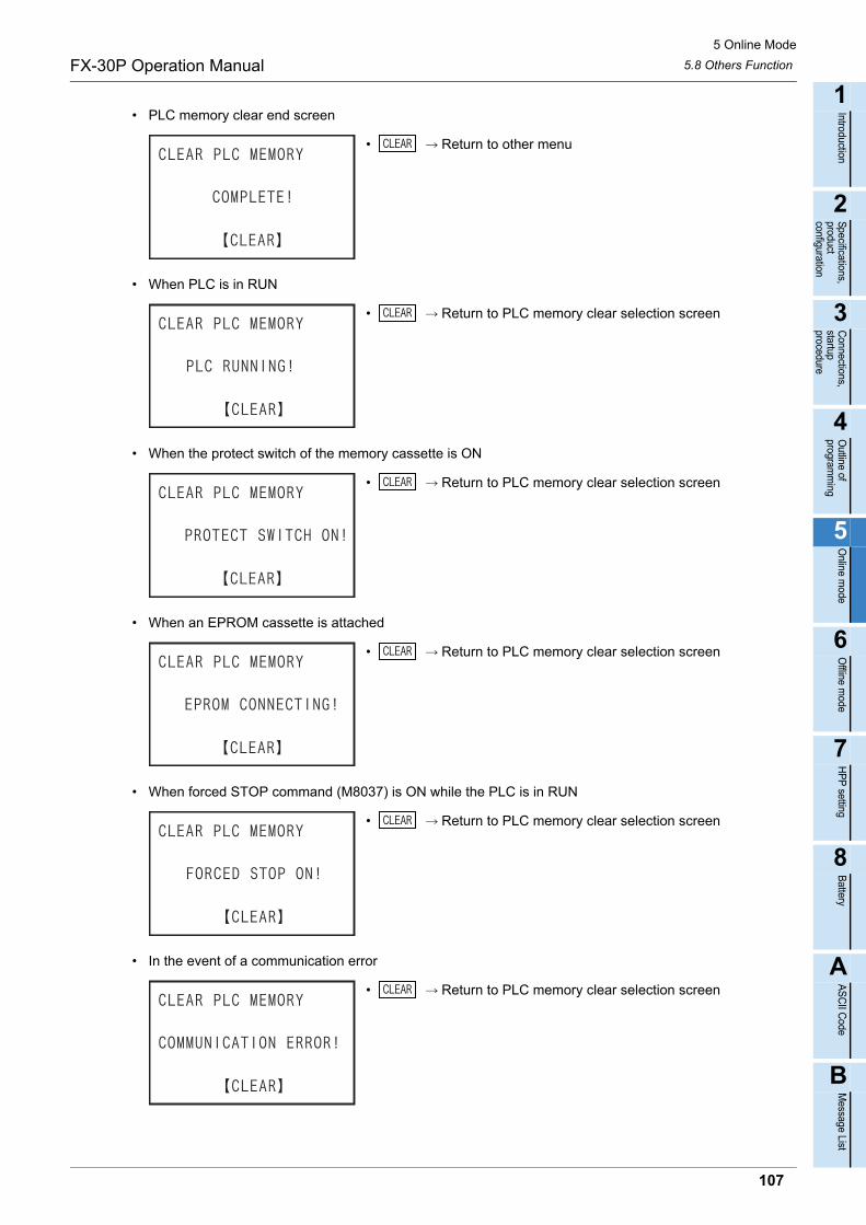
5 Online Mode
5.8 Others FunctionFX-30P Operation Manual
1
Introduction
2
Specifications,product configuration
3
Connections,
startup procedure
4
Outline of
programm
ing
5
Online m
ode
6
Offline m
ode
7
HP
P setting
8
Battery
A
AS
CII C
ode
B
Message List
• PLC memory clear end screen
• Return to other menu
• When PLC is in RUN
• Return to PLC memory clear selection screen
• When the protect switch of the memory cassette is ON
• Return to PLC memory clear selection screen
• When an EPROM cassette is attached
• Return to PLC memory clear selection screen
• When forced STOP command (M8037) is ON while the PLC is in RUN
• Return to PLC memory clear selection screen
• In the event of a communication error
• Return to PLC memory clear selection screen
107
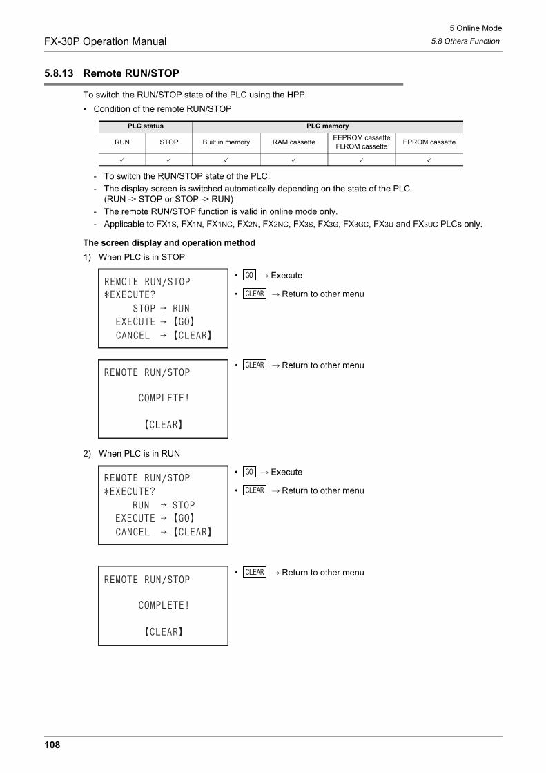
5 Online Mode
5.8 Others FunctionFX-30P Operation Manual
5.8.13 Remote RUN/STOP
To switch the RUN/STOP state of the PLC using the HPP.
• Condition of the remote RUN/STOP
- To switch the RUN/STOP state of the PLC.
- The display screen is switched automatically depending on the state of the PLC.(RUN -> STOP or STOP -> RUN)
- The remote RUN/STOP function is valid in online mode only.
- Applicable to FX1S, FX1N, FX1NC, FX2N, FX2NC, FX3S, FX3G, FX3GC, FX3U and FX3UC PLCs only.
The screen display and operation method
1) When PLC is in STOP
• Execute
• Return to other menu
• Return to other menu
2) When PLC is in RUN
• Execute
• Return to other menu
• Return to other menu
PLC status PLC memory
RUN STOP Built in memory RAM cassetteEEPROM cassetteFLROM cassette
EPROM cassette
108
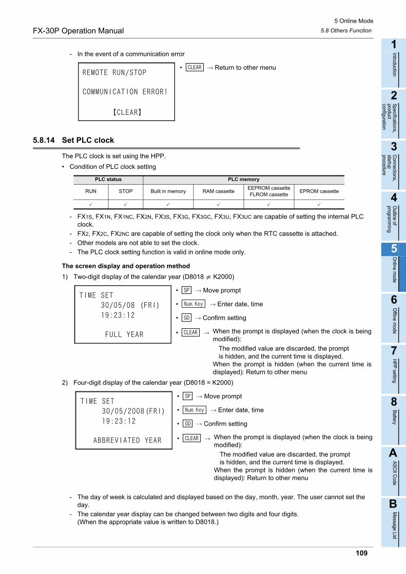
5 Online Mode
5.8 Others FunctionFX-30P Operation Manual
1
Introduction
2
Specifications,product configuration
3
Connections,
startup procedure
4
Outline of
programm
ing
5
Online m
ode
6
Offline m
ode
7
HP
P setting
8
Battery
A
AS
CII C
ode
B
Message List
- In the event of a communication error
• Return to other menu
5.8.14 Set PLC clock
The PLC clock is set using the HPP.
• Condition of PLC clock setting
- FX1S, FX1N, FX1NC, FX2N, FX3S, FX3G, FX3GC, FX3U, FX3UC are capable of setting the internal PLC clock.
- FX2, FX2C, FX2NC are capable of setting the clock only when the RTC cassette is attached.
- Other models are not able to set the clock.
- The PLC clock setting function is valid in online mode only.
The screen display and operation method
1) Two-digit display of the calendar year (D8018 K2000)
• Move prompt
• Enter date, time
• Confirm setting
2) Four-digit display of the calendar year (D8018 = K2000)
• Move prompt
• Enter date, time
• Confirm setting
- The day of week is calculated and displayed based on the day, month, year. The user cannot set the day.
- The calendar year display can be changed between two digits and four digits.(When the appropriate value is written to D8018.)
PLC status PLC memory
RUN STOP Built in memory RAM cassetteEEPROM cassetteFLROM cassette
EPROM cassette
• When the prompt is displayed (when the clock is beingmodified):
The modified value are discarded, the promptis hidden, and the current time is displayed.
When the prompt is hidden (when the current time isdisplayed): Return to other menu
• When the prompt is displayed (when the clock is beingmodified):
The modified value are discarded, the promptis hidden, and the current time is displayed.
When the prompt is hidden (when the current time isdisplayed): Return to other menu
109

6 Offline mode
6.1 Outline of offline modeFX-30P Operation Manual
6. Offline mode
6.1 Outline of offline mode
In the offline mode, the HPP accesses the built in 30P RAM.Programs written to the built in 30P RAM can be batch-transferred to the built in PLC RAM or a memorycassette attached to the PLC. Firmware version 1.10 or later supports the HPP-PC TRANSFER function.As for the functions similar to those in the online mode (read, write, insert, delete, parameter, deviceconversion), refer to Chapter 5. As for setting of the HPP, refer to Chapter 7.
• Programming in the offline mode is executed to the built in 30P RAM regardless of the program memory type in and the RUN/STOP status of the PLC.
• The batch transfer operation to the PLC can be performed in the following conditions.
*1. When protect switch is OFF
Role of built in 30P RAMIn the offline mode, programming is executed to the built in 30P RAM.Even if programming is executed to another PLC in the online mode by using the 30P programmed in theoffline mode, programs saved in the 30P remain saved as they are. However, when the program istransferred and read out from the PLC in offline mode, the original program in the 30P is erased.
Role of built in 30P battery The built in 30P RAM is protected from power failure by the built in 30P battery. Therefore, from the 30P inwhich the program is entered in offline mode, you can transfer and write to another PLC.
RUN/STOP status of PLC Program memory in PLC
Write from HPP to PLC STOP RAM EEPROM*1 FLROM*1
Read from PLC to HPPRUN/STOP RAM EEPROM FLROM EPROM
Collation between HPP and PLC
110

6 Offline mode
6.2 Others FunctionsFX-30P Operation Manual
1
Introduction
2
Specifications,product configuration
3
Connections,
startup procedure
4
Outline of
programm
ing
5
Online m
ode
6
Offline m
ode
7
HP
P setting
8
Battery
A
AS
CII C
ode
B
Message List
6.2 Others Functions
When key is pressed once, the OTHER function list is displayed, and when pressed again, theHELP is displayed, and when pressed once more, the display returns to the "OTHER" function list display.(Transfer to alternate)
6.2.1 Outline of others function
• Even while a program operation is being performed, pressing the key displays the others menu screen.
• In the others function in offline mode, the following settings are available.
- CHANGE TO ONLINE (OFFLINE ONLINE)
- PROGRAM CHECK
- HPP-FX TRANSFER
- HPP-PC TRANSFER
- PARAMETER
- DEVICE CONVERSION
- CHANGE PLC TYPE
- HPP MEMORY CLEAR
- PROGRAM MANAGER
- HPP SETTING
• As for parameters, refer to Subsection 5.8.5, and as for the device conversion, refer to Subsection 5.8.7. As for HPP setting, refer to Chapter 7.
• For firmware versions that support the HPP-PC TRANSFER function, refer to Subsection 6.2.5.
"Others" menu screen when offline mode is selected (Firmware versions 1.10 or later)
• , Move cursor
• Confirm selection
• Select
• Return to other menu
- Items 1 to A can be selected and set by numeric keys to .
*1. If "HPP-PC TRANSFER" is selected in the offline mode when the PLC type is other than FX3S,FX3G(C) or FX3U(C), screen does not change.
*1
111
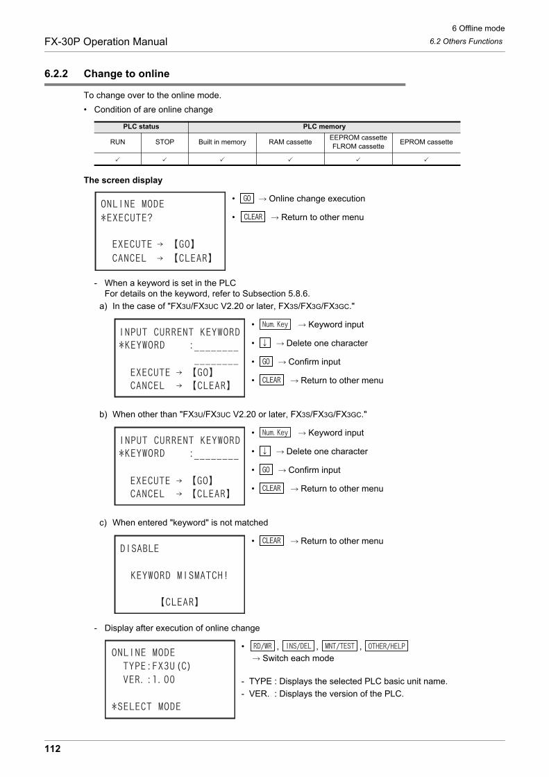
6 Offline mode
6.2 Others FunctionsFX-30P Operation Manual
6.2.2 Change to online
To change over to the online mode.
• Condition of are online change
The screen display
• Online change execution
• Return to other menu
- When a keyword is set in the PLCFor details on the keyword, refer to Subsection 5.8.6.
a) In the case of "FX3U/FX3UC V2.20 or later, FX3S/FX3G/FX3GC."
• Keyword input
• Delete one character
• Confirm input
• Return to other menu
b) When other than "FX3U/FX3UC V2.20 or later, FX3S/FX3G/FX3GC."
• Keyword input
• Delete one character
• Confirm input
• Return to other menu
c) When entered "keyword" is not matched
• Return to other menu
- Display after execution of online change
• , , , Switch each mode
- TYPE : Displays the selected PLC basic unit name.
- VER. : Displays the version of the PLC.
PLC status PLC memory
RUN STOP Built in memory RAM cassetteEEPROM cassetteFLROM cassette
EPROM cassette
112

6 Offline mode
6.2 Others FunctionsFX-30P Operation Manual
1
Introduction
2
Specifications,product configuration
3
Connections,
startup procedure
4
Outline of
programm
ing
5
Online m
ode
6
Offline m
ode
7
HP
P setting
8
Battery
A
AS
CII C
ode
B
Message List
6.2.3 Program check
The program check in offline mode includes checking of "PARAMETER ERROR", "SYNTAX ERROR", and"LADDER ERROR" only.If an error is found after program check, the error number, error classification, error code, and erroroccurrence step number are displayed.
If multiple errors occur, other errors can be displayed by using or key. As for the error list, refer toSubsection 5.8.3.
• Program check condition
- The program is checked in the built in 30P RAM (judged at the 30P side).
- The program of built in 30P flash memory can be checked after being read out into the built in RAM.
The screen display
1) Program check top screen
• Program check execution
• Return to other menu
2) In the absence of error
• Return to other menu
PLC status PLC memory
RUN STOP Built in memory RAM cassetteEEPROM cassetteFLROM cassette
EPROM cassette
113
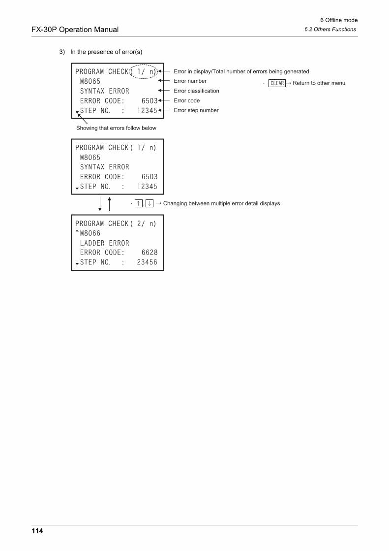
6 Offline mode
6.2 Others FunctionsFX-30P Operation Manual
3) In the presence of error(s)
Showing that errors follow below
Error in display/Total number of errors being generated
Error number
Error classification
Error code
Error step number
Changing between multiple error detail displays
Return to other menu
,
114
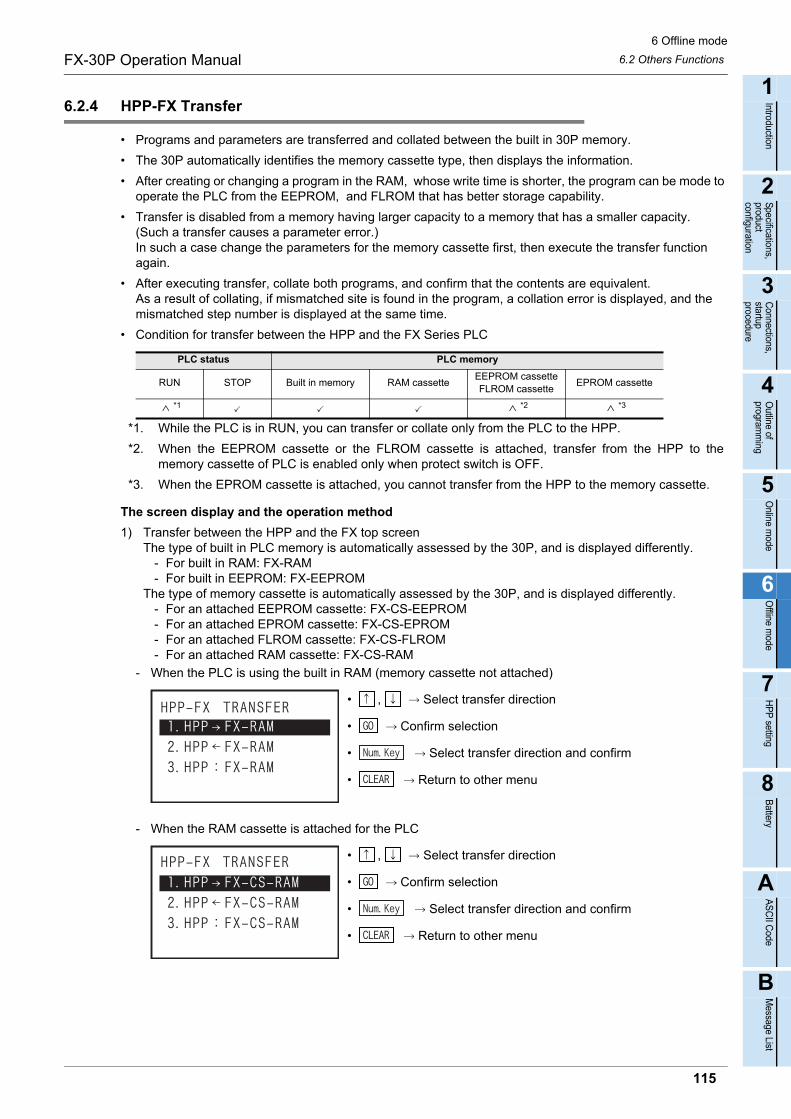
6 Offline mode
6.2 Others FunctionsFX-30P Operation Manual
1
Introduction
2
Specifications,product configuration
3
Connections,
startup procedure
4
Outline of
programm
ing
5
Online m
ode
6
Offline m
ode
7
HP
P setting
8
Battery
A
AS
CII C
ode
B
Message List
6.2.4 HPP-FX Transfer
• Programs and parameters are transferred and collated between the built in 30P memory.
• The 30P automatically identifies the memory cassette type, then displays the information.
• After creating or changing a program in the RAM, whose write time is shorter, the program can be mode to operate the PLC from the EEPROM, and FLROM that has better storage capability.
• Transfer is disabled from a memory having larger capacity to a memory that has a smaller capacity.(Such a transfer causes a parameter error.)In such a case change the parameters for the memory cassette first, then execute the transfer function again.
• After executing transfer, collate both programs, and confirm that the contents are equivalent.As a result of collating, if mismatched site is found in the program, a collation error is displayed, and the mismatched step number is displayed at the same time.
• Condition for transfer between the HPP and the FX Series PLC
*1. While the PLC is in RUN, you can transfer or collate only from the PLC to the HPP.
*2. When the EEPROM cassette or the FLROM cassette is attached, transfer from the HPP to thememory cassette of PLC is enabled only when protect switch is OFF.
*3. When the EPROM cassette is attached, you cannot transfer from the HPP to the memory cassette.
The screen display and the operation method
1) Transfer between the HPP and the FX top screenThe type of built in PLC memory is automatically assessed by the 30P, and is displayed differently.
- For built in RAM: FX-RAM - For built in EEPROM: FX-EEPROM
The type of memory cassette is automatically assessed by the 30P, and is displayed differently. - For an attached EEPROM cassette: FX-CS-EEPROM - For an attached EPROM cassette: FX-CS-EPROM - For an attached FLROM cassette: FX-CS-FLROM - For an attached RAM cassette: FX-CS-RAM
- When the PLC is using the built in RAM (memory cassette not attached)
• , Select transfer direction
• Confirm selection
• Select transfer direction and confirm
• Return to other menu
- When the RAM cassette is attached for the PLC
• , Select transfer direction
• Confirm selection
• Select transfer direction and confirm
• Return to other menu
PLC status PLC memory
RUN STOP Built in memory RAM cassetteEEPROM cassetteFLROM cassette
EPROM cassette
*1 *2 *3
115
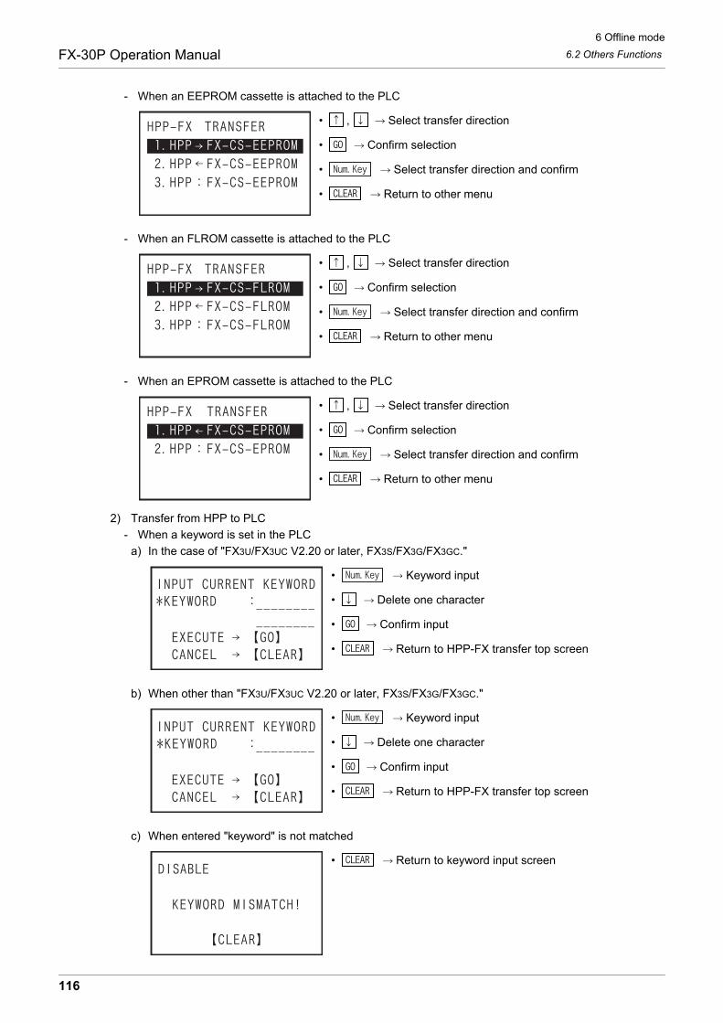
6 Offline mode
6.2 Others FunctionsFX-30P Operation Manual
- When an EEPROM cassette is attached to the PLC
• , Select transfer direction
• Confirm selection
• Select transfer direction and confirm
• Return to other menu
- When an FLROM cassette is attached to the PLC
• , Select transfer direction
• Confirm selection
• Select transfer direction and confirm
• Return to other menu
- When an EPROM cassette is attached to the PLC
• , Select transfer direction
• Confirm selection
• Select transfer direction and confirm
• Return to other menu
2) Transfer from HPP to PLC
- When a keyword is set in the PLC
a) In the case of "FX3U/FX3UC V2.20 or later, FX3S/FX3G/FX3GC."
• Keyword input
• Delete one character
• Confirm input
• Return to HPP-FX transfer top screen
b) When other than "FX3U/FX3UC V2.20 or later, FX3S/FX3G/FX3GC."
• Keyword input
• Delete one character
• Confirm input
• Return to HPP-FX transfer top screen
c) When entered "keyword" is not matched
• Return to keyword input screen
116
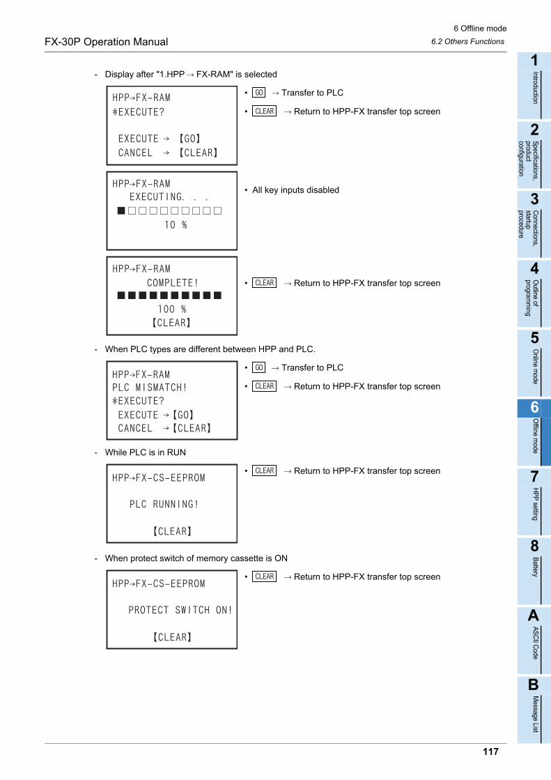
6 Offline mode
6.2 Others FunctionsFX-30P Operation Manual
1
Introduction
2
Specifications,product configuration
3
Connections,
startup procedure
4
Outline of
programm
ing
5
Online m
ode
6
Offline m
ode
7
HP
P setting
8
Battery
A
AS
CII C
ode
B
Message List
- Display after "1.HPP FX-RAM" is selected
• Transfer to PLC
• Return to HPP-FX transfer top screen
• All key inputs disabled
• Return to HPP-FX transfer top screen
- When PLC types are different between HPP and PLC.
• Transfer to PLC
• Return to HPP-FX transfer top screen
- While PLC is in RUN
• Return to HPP-FX transfer top screen
- When protect switch of memory cassette is ON
• Return to HPP-FX transfer top screen
117
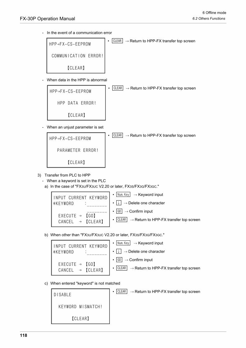
6 Offline mode
6.2 Others FunctionsFX-30P Operation Manual
- In the event of a communication error
• Return to HPP-FX transfer top screen
- When data in the HPP is abnormal
• Return to HPP-FX transfer top screen
- When an unjust parameter is set
• Return to HPP-FX transfer top screen
3) Transfer from PLC to HPP
- When a keyword is set in the PLC
a) In the case of "FX3U/FX3UC V2.20 or later, FX3S/FX3G/FX3GC."
• Keyword input
• Delete one character
• Confirm input
• Return to HPP-FX transfer top screen
b) When other than "FX3U/FX3UC V2.20 or later, FX3S/FX3G/FX3GC."
• Keyword input
• Delete one character
• Confirm input
• Return to HPP-FX transfer top screen
c) When entered "keyword" is not matched
• Return to HPP-FX transfer top screen
118
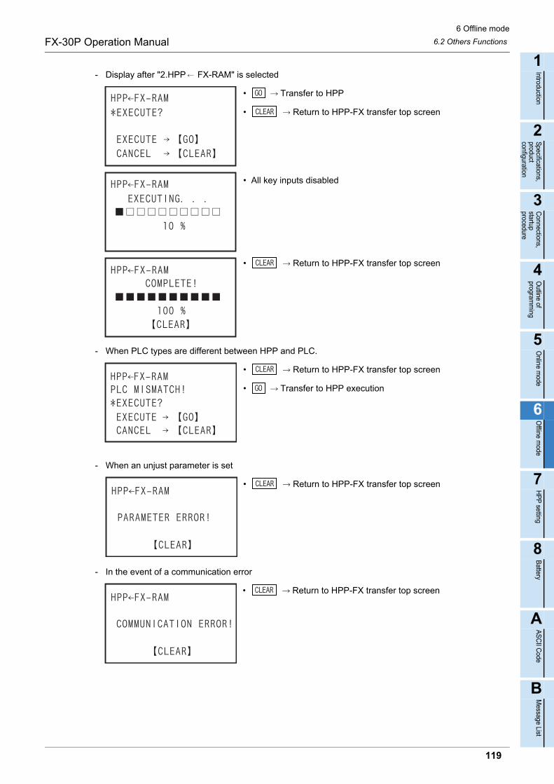
6 Offline mode
6.2 Others FunctionsFX-30P Operation Manual
1
Introduction
2
Specifications,product configuration
3
Connections,
startup procedure
4
Outline of
programm
ing
5
Online m
ode
6
Offline m
ode
7
HP
P setting
8
Battery
A
AS
CII C
ode
B
Message List
- Display after "2.HPP FX-RAM" is selected
• Transfer to HPP
• Return to HPP-FX transfer top screen
• All key inputs disabled
• Return to HPP-FX transfer top screen
- When PLC types are different between HPP and PLC.
• Return to HPP-FX transfer top screen
• Transfer to HPP execution
- When an unjust parameter is set
• Return to HPP-FX transfer top screen
- In the event of a communication error
• Return to HPP-FX transfer top screen
119
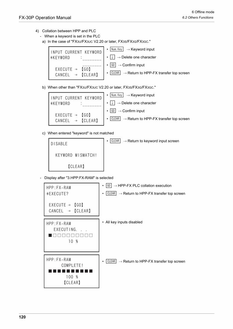
6 Offline mode
6.2 Others FunctionsFX-30P Operation Manual
4) Collation between HPP and PLC
- When a keyword is set in the PLC
a) In the case of "FX3U/FX3UC V2.20 or later, FX3S/FX3G/FX3GC."
• Keyword input
• Delete one character
• Confirm input
• Return to HPP-FX transfer top screen
b) When other than "FX3U/FX3UC V2.20 or later, FX3S/FX3G/FX3GC."
• Keyword input
• Delete one character
• Confirm input
• Return to HPP-FX transfer top screen
c) When entered "keyword" is not matched
• Return to keyword input screen
- Display after "3.HPP:FX-RAM" is selected
• HPP-FX PLC collation execution
• Return to HPP-FX transfer top screen
• All key inputs disabled
• Return to HPP-FX transfer top screen
120

6 Offline mode
6.2 Others FunctionsFX-30P Operation Manual
1
Introduction
2
Specifications,product configuration
3
Connections,
startup procedure
4
Outline of
programm
ing
5
Online m
ode
6
Offline m
ode
7
HP
P setting
8
Battery
A
AS
CII C
ode
B
Message List
- In the event of a collation error or parameter mismatch
• Return to HPP-FX transfer top screen
- In the event of a collation error or program mismatch
• Return to HPP-FX transfer top screen
- In the event of a communication error
• Return to HPP-FX transfer top screen
121
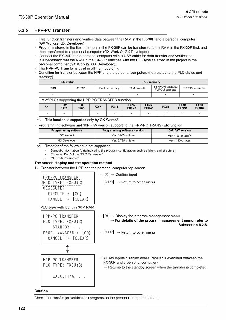
6 Offline mode
6.2 Others FunctionsFX-30P Operation Manual
6.2.5 HPP-PC Transfer
• This function transfers and verifies data between the RAM in the FX-30P and a personal computer(GX Works2, GX Developer).
• Programs stored in the flash memory in the FX-30P can be transferred to the RAM in the FX-30P first, and then transferred to a personal computer (GX Works2, GX Developer).
• Connect the FX-30P and a personal computer with a USB cable for data transfer and verification.• It is necessary that the RAM in the FX-30P matches with the PLC type selected in the project in the
personal computer (GX Works2, GX Developer).• The HPP-PC Transfer is valid in offline mode only.• Condition for transfer between the HPP and the personal computers (not related to the PLC status and
memory)
• List of PLCs supporting the HPP-PC TRANSFER function
*1. This function is supported only by GX Works2.
• Programming software and 30P F/W version supporting the HPP-PC TRANSFER function
*2. Transfer of the following is not supported.- Symbolic information (data indicating the program configuration such as labels and structure)- "Ethernet Port" of the "PLC Parameter"- "Network Parameter"
The screen display and the operation method
1) Transfer between the HPP and the personal computer top screen
• Confirm input
• Return to other menu
• Display the program management menuFor details of the program management menu, refer to
Subsection 6.2.8.
• Return to other menu
• All key inputs disabled (while transfer is executed between theFX-30P and a personal computer)
Returns to the standby screen when the transfer is completed.
Caution
Check the transfer (or verification) progress on the personal computer screen.
PLC status PLC memory
RUN STOP Built in memory RAM cassette EEPROM cassetteFLROM cassette EPROM cassette
- - - - - -
FX1FX2
FX2CFX0
FX0SFX0N FX1S FX1N
FX1NCFX2N
FX2NCFX3S
FX3GFX3GC
FX3UFX3UC
- - - - - - - *1
Programming software Programming software version 30P F/W version
GX Works2 Ver. 1.91V or later Ver. 1.50 or later*2
GX Developer Ver. 8.72A or later Ver. 1.10 or later
122
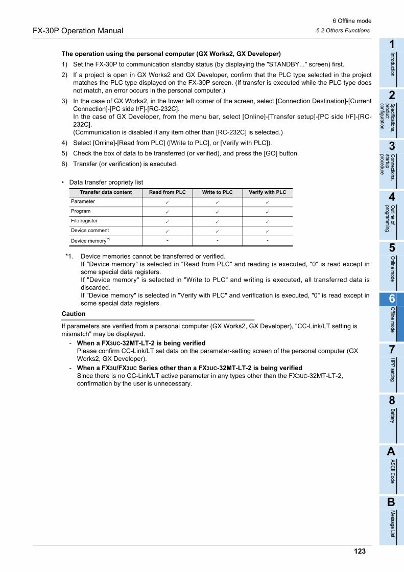
6 Offline mode
6.2 Others FunctionsFX-30P Operation Manual
1
Introduction
2
Specifications,product configuration
3
Connections,
startup procedure
4
Outline of
programm
ing
5
Online m
ode
6
Offline m
ode
7
HP
P setting
8
Battery
A
AS
CII C
ode
B
Message List
The operation using the personal computer (GX Works2, GX Developer)
1) Set the FX-30P to communication standby status (by displaying the "STANDBY..." screen) first.
2) If a project is open in GX Works2 and GX Developer, confirm that the PLC type selected in the projectmatches the PLC type displayed on the FX-30P screen. (If transfer is executed while the PLC type doesnot match, an error occurs in the personal computer.)
3) In the case of GX Works2, in the lower left corner of the screen, select [Connection Destination]-[CurrentConnection]-[PC side I/F]-[RC-232C].In the case of GX Developer, from the menu bar, select [Online]-[Transfer setup]-[PC side I/F]-[RC-232C].(Communication is disabled if any item other than [RC-232C] is selected.)
4) Select [Online]-[Read from PLC] ([Write to PLC], or [Verify with PLC]).
5) Check the box of data to be transferred (or verified), and press the [GO] button.
6) Transfer (or verification) is executed.
• Data transfer propriety list
*1. Device memories cannot be transferred or verified.If "Device memory" is selected in "Read from PLC" and reading is executed, "0" is read except insome special data registers.If "Device memory" is selected in "Write to PLC" and writing is executed, all transferred data isdiscarded.If "Device memory" is selected in "Verify with PLC" and verification is executed, "0" is read except insome special data registers.
Caution
If parameters are verified from a personal computer (GX Works2, GX Developer), "CC-Link/LT setting is mismatch" may be displayed.
- When a FX3UC-32MT-LT-2 is being verifiedPlease confirm CC-Link/LT set data on the parameter-setting screen of the personal computer (GX Works2, GX Developer).
- When a FX3U/FX3UC Series other than a FX3UC-32MT-LT-2 is being verifiedSince there is no CC-Link/LT active parameter in any types other than the FX3UC-32MT-LT-2, confirmation by the user is unnecessary.
Transfer data content Read from PLC Write to PLC Verify with PLC
Parameter
Program
File register
Device comment
Device memory*1 - - -
123
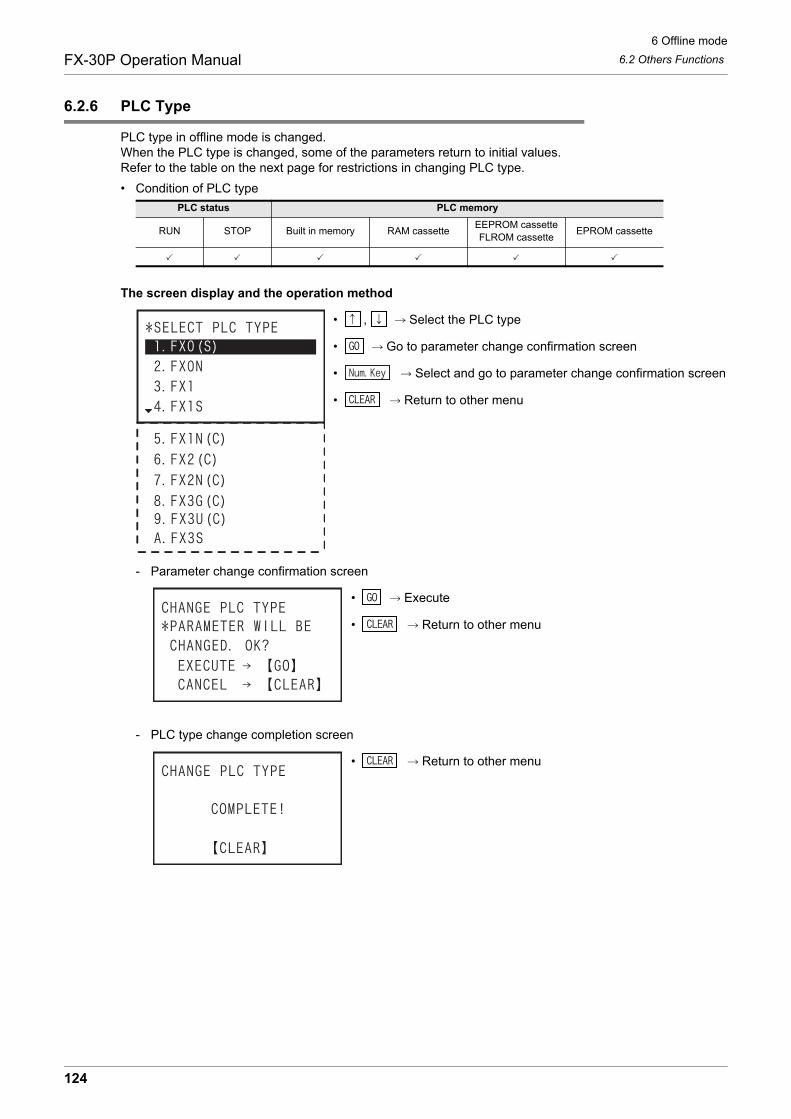
6 Offline mode
6.2 Others FunctionsFX-30P Operation Manual
6.2.6 PLC Type
PLC type in offline mode is changed.When the PLC type is changed, some of the parameters return to initial values.Refer to the table on the next page for restrictions in changing PLC type.
• Condition of PLC type
The screen display and the operation method
• , Select the PLC type
• Go to parameter change confirmation screen
• Select and go to parameter change confirmation screen
• Return to other menu
- Parameter change confirmation screen
• Execute
• Return to other menu
- PLC type change completion screen
• Return to other menu
PLC status PLC memory
RUN STOP Built in memory RAM cassetteEEPROM cassetteFLROM cassette
EPROM cassette
124

6 Offline mode
6.2 Others FunctionsFX-30P Operation Manual
1
Introduction
2
Specifications,product configuration
3
Connections,
startup procedure
4
Outline of
programm
ing
5
Online m
ode
6
Offline m
ode
7
HP
P setting
8
Battery
A
AS
CII C
ode
B
Message List
• Changes Made between PLC Types
: Settings before change are retained.: The status before change is retained when the setting range is allowed in the change destination PLCtype. The initial setting of the change destination PLC type is set when the selected setting range isnot allowed.
: Defaults of the CPU type after change are set. - : Not applicable.
*1. The value in () is the initial setting for each PLC type.
Change TypeMemory
Capacity*1
Comment
Capacity*1
File Register
Capacity*1LatchRange
PLC System Setting
FX0(S) FX0N (2000 steps) (Block 0) (Block 0) - -
FX0(S) FX1 (2000 steps) - -
FX0(S) FX1N(C) (8000 steps) (Block 0) (Block 0) -
FX0(S) FX1S (2000 steps) (Block 0) (Block 0) -
FX0(S) FX2(C) (2000 steps) (Block 0) (Block 0) -
FX0(S) FX2N(C) (8000 steps) (Block 0) (Block 0)
FX0(S) FX3S (4000 steps) (Block 0) (Block 0) -
FX0(S) FX3G(C) (8000 steps) (Block 0) (Block 0) -
FX0(S) FX3U(C) (8000 steps) (Block 0) (Block 0)
FX0N FX0(S) (800 steps) - - - -
FX0N FX1 - -
FX0N FX1S -
FX0N FX1N(C) -
FX0N FX2(C) -
FX0N FX2N(C)
FX0N FX3S -
FX0N FX3G(C) -
FX0N FX3U(C)
FX1 FX0(S) (800 steps) - - - -
FX1 FX0N (2000 steps) (Block 0) (Block 0) - -
FX1 FX1S (2000 steps) (Block 0) (Block 0) -
FX1 FX1N(C) (Block 0) (Block 0) -
FX1 FX2(C) (Block 0) (Block 0) -
FX1 FX2N(C) (Block 0) (Block 0)
FX1 FX3S (Block 0) (Block 0) -
FX1 FX3G(C) (Block 0) (Block 0) -
FX1 FX3U(C) (Block 0) (Block 0)
FX1S FX0(S) (800 steps) - - - -
FX1S FX0N - -
FX1S FX1 - -
FX1S FX1N(C) -
FX1S FX2(C) -
FX1S FX2N(C)
FX1S FX3S -
FX1S FX3G(C) -
FX1S FX3U(C)
125

6 Offline mode
6.2 Others FunctionsFX-30P Operation Manual
: Settings before change are retained.: The status before change is retained when the setting range is allowed in the change destination PLCtype. The initial setting of the change destination PLC type is set when the selected setting range isnot allowed.
: Defaults of the CPU type after change are set. - : Not applicable.
*1. The value in () is the initial setting for each PLC type.
*2. When PLC type is changed to FX1 and the memory capacity is 4K step, the initial value of thecomment capacity becomes 4 blocks (2K step).
*3. When PLC type is changed to FX3S and the memory capacity is 16K step, the initial value of thecomment capacity is the value of 24 blocks (12K step) minus the file register capacity.
Change TypeMemory
Capacity*1
Comment
Capacity*1
File Register
Capacity*1LatchRange
PLC System Setting
FX1N(C) FX0(S) (800 steps) - - - -
FX1N(C) FX0N (2000 steps) (Block 0) (Block 0) - -
FX1N(C) FX1 (2000 steps) (Block 0)*2 - -
FX1N(C) FX1S (2000 steps) (Block 0) (Block 0) -
FX1N(C) FX2(C) (Block 0) (Block 0) -
FX1N(C) FX2N(C)
FX1N(C) FX3S (4000 steps) (Block 0) (Block 0) -
FX1N(C) FX3G(C) -
FX1N(C) FX3U(C)
FX2(C) FX0(S) (800 steps) - - - -
FX2(C) FX0N (2000 steps) (Block 0) (Block 0) - -
FX2(C) FX1 (2000 steps) (Block 0)*2 - -
FX2(C) FX1S (2000 steps) (Block 0) (Block 0) -
FX2(C) FX1N(C) (Block 0) (Block 0) -
FX2(C) FX2N(C) (Block 0) (Block 0)
FX2(C) FX3S (4000 steps) (Block 0) (Block 0) -
FX2(C) FX3G(C) (Block 0) (Block 0) -
FX2(C) FX3U(C) (Block 0) (Block 0)
FX2N(C) FX0(S) (800 steps) - - - -
FX2N(C) FX0N (2000 steps) (Block 0) (Block 0) - -
FX2N(C) FX1 (2000 steps) (Block 0)*2 - -
FX2N(C) FX1S (2000 steps) (Block 0) (Block 0) -
FX2N(C) FX1N(C) (8000 steps) (Block 0) (Block 0) -
FX2N(C) FX2(C) (2000 steps) (Block 0) (Block 0) -
FX2N(C) FX3S (4000 steps) (Block 0)*3 (Block 0) -
FX2N(C) FX3G(C) -
FX2N(C) FX3U(C)
126
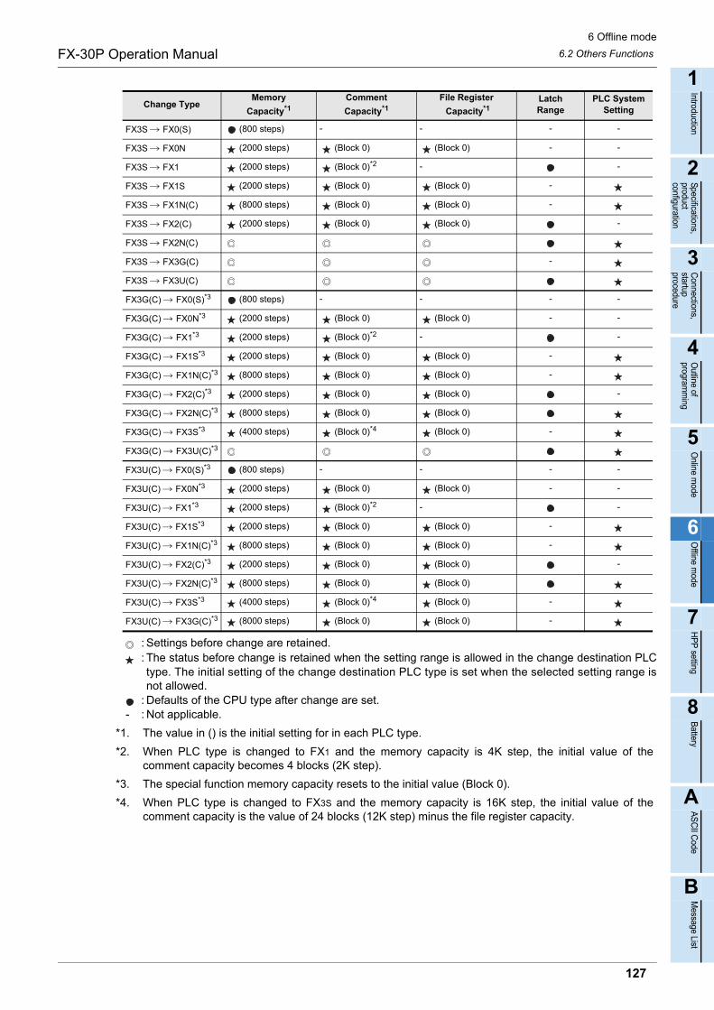
6 Offline mode
6.2 Others FunctionsFX-30P Operation Manual
1
Introduction
2
Specifications,product configuration
3
Connections,
startup procedure
4
Outline of
programm
ing
5
Online m
ode
6
Offline m
ode
7
HP
P setting
8
Battery
A
AS
CII C
ode
B
Message List
: Settings before change are retained.: The status before change is retained when the setting range is allowed in the change destination PLCtype. The initial setting of the change destination PLC type is set when the selected setting range isnot allowed.
: Defaults of the CPU type after change are set. - : Not applicable.
*1. The value in () is the initial setting for in each PLC type.
*2. When PLC type is changed to FX1 and the memory capacity is 4K step, the initial value of thecomment capacity becomes 4 blocks (2K step).
*3. The special function memory capacity resets to the initial value (Block 0).
*4. When PLC type is changed to FX3S and the memory capacity is 16K step, the initial value of thecomment capacity is the value of 24 blocks (12K step) minus the file register capacity.
Change TypeMemory
Capacity*1
Comment
Capacity*1
File Register
Capacity*1LatchRange
PLC System Setting
FX3S FX0(S) (800 steps) - - - -
FX3S FX0N (2000 steps) (Block 0) (Block 0) - -
FX3S FX1 (2000 steps) (Block 0)*2 - -
FX3S FX1S (2000 steps) (Block 0) (Block 0) -
FX3S FX1N(C) (8000 steps) (Block 0) (Block 0) -
FX3S FX2(C) (2000 steps) (Block 0) (Block 0) -
FX3S FX2N(C)
FX3S FX3G(C) -
FX3S FX3U(C)
FX3G(C) FX0(S)*3 (800 steps) - - - -
FX3G(C) FX0N*3 (2000 steps) (Block 0) (Block 0) - -
FX3G(C) FX1*3 (2000 steps) (Block 0)*2 - -
FX3G(C) FX1S*3 (2000 steps) (Block 0) (Block 0) -
FX3G(C) FX1N(C)*3 (8000 steps) (Block 0) (Block 0) -
FX3G(C) FX2(C)*3 (2000 steps) (Block 0) (Block 0) -
FX3G(C) FX2N(C)*3 (8000 steps) (Block 0) (Block 0)
FX3G(C) FX3S*3 (4000 steps) (Block 0)*4 (Block 0) -
FX3G(C) FX3U(C)*3
FX3U(C) FX0(S)*3 (800 steps) - - - -
FX3U(C) FX0N*3 (2000 steps) (Block 0) (Block 0) - -
FX3U(C) FX1*3 (2000 steps) (Block 0)*2 - -
FX3U(C) FX1S*3 (2000 steps) (Block 0) (Block 0) -
FX3U(C) FX1N(C)*3 (8000 steps) (Block 0) (Block 0) -
FX3U(C) FX2(C)*3 (2000 steps) (Block 0) (Block 0) -
FX3U(C) FX2N(C)*3 (8000 steps) (Block 0) (Block 0)
FX3U(C) FX3S*3 (4000 steps) (Block 0)*4 (Block 0) -
FX3U(C) FX3G(C)*3 (8000 steps) (Block 0) (Block 0) -
127
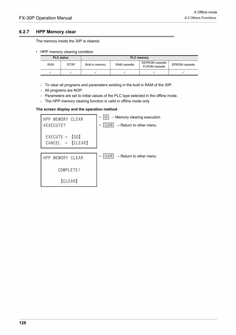
6 Offline mode
6.2 Others FunctionsFX-30P Operation Manual
6.2.7 HPP Memory clear
The memory inside the 30P is cleared.
• HPP memory clearing condition
- To clear all programs and parameters existing in the built in RAM of the 30P.
- All programs are NOP.
- Parameters are set to initial values of the PLC type selected in the offline mode.
- The HPP memory clearing function is valid in offline mode only.
The screen display and the operation method
• Memory clearing execution
• Return to other menu
• Return to other menu
PLC status PLC memory
RUN STOP Built in memory RAM cassetteEEPROM cassetteFLROM cassette
EPROM cassette
128

6 Offline mode
6.2 Others FunctionsFX-30P Operation Manual
1
Introduction
2
Specifications,product configuration
3
Connections,
startup procedure
4
Outline of
programm
ing
5
Online m
ode
6
Offline m
ode
7
HP
P setting
8
Battery
A
AS
CII C
ode
B
Message List
6.2.8 Program manager
This is to manage the programs saved in the flash memory inside the 30P.
• Condition of program management
- You can access the menus for new program save, program overwrite save, program read-out, program delete, program management information, etc.
- The program management function is valid in offline mode only.
• Program save capacity
Up to 15 programs can be saved.
• Program composition (data which can be saved)
• 30P built in flash memory performance
• Program management menu
*1. When editing the program in the 30P program management area, you must read out into the built in30P RAM. When being read out, the program originally existing in the built in 30P RAM is lost (due tobeing overwritten).
*2. Only the program in the 30P program management area is deleted. The program in the built in 30PRAM is not deleted.
*3. When saving a program for the first time, you must designate "program management name" to bemanaged in the 30P. Refer to the paragraph on program management name setting.
PLC status PLC memory
RUN STOP Built in memory RAM cassetteEEPROM cassetteFLROM cassette
EPROM cassette
Total capacity Number of blocks being used in the program memory capacity
15 blocksProgram memory capacity is 800, 2K, 4K, 16K, 32K steps: 1 block usedProgram memory capacity is 64K steps: 2 blocks used
Item Capacity
Parameter -
Program 800, 2K, 4K, 8K, 16K, 32K, 64K steps
Item Description
Allowable number of writes Each block 100,000 times
Item Function
Program list To display a list of programs stored in the 30P program management area (built in 30P flash memory).
READ To read out the program selected from the program list, to the built in 30P RAM.*1
RESAVEThe program in the built in 30P RAM is overwritten and saved in the program selected from the programlist.
DELETE To delete the program selected from the program list.*2
NEW SAVEThe program in the built in 30P RAM is newly saved in the 30P program management area (built in 30P
flash memory).*3
ALL DELETE To delete all programs in the 30P program management area (built in 30P flash memory).
PROG. MANAGER INF.To display the number of programs saved in the 30P program management area (built in 30P flashmemory) together with the number of blocks being used.
129
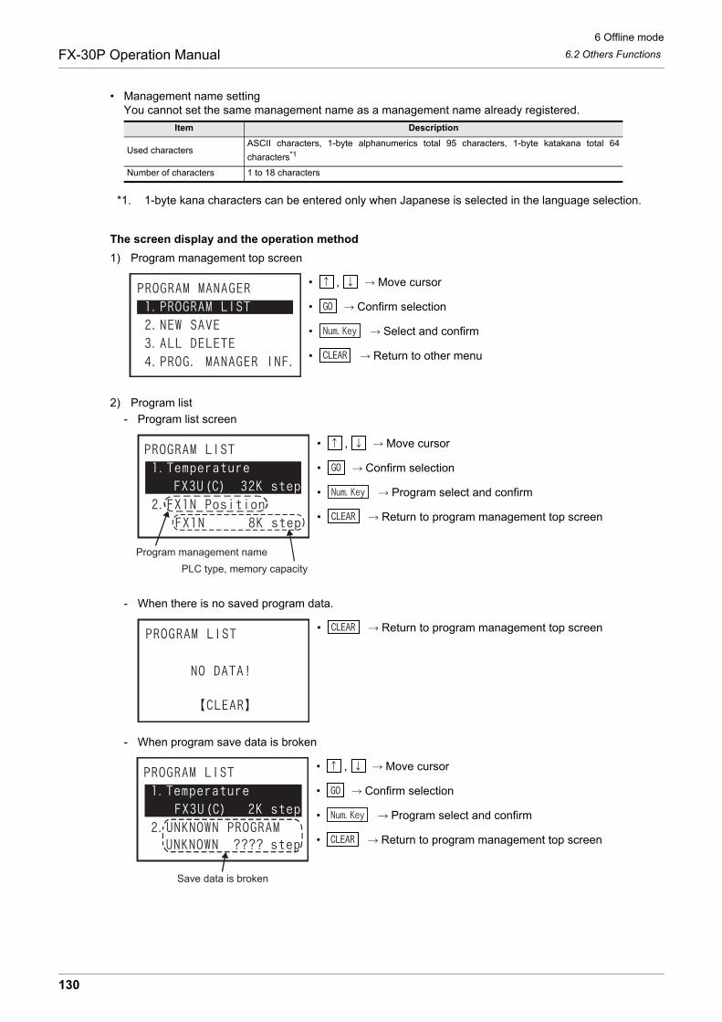
6 Offline mode
6.2 Others FunctionsFX-30P Operation Manual
• Management name settingYou cannot set the same management name as a management name already registered.
*1. 1-byte kana characters can be entered only when Japanese is selected in the language selection.
The screen display and the operation method
1) Program management top screen
• , Move cursor
• Confirm selection
• Select and confirm
• Return to other menu
2) Program list
- Program list screen
• , Move cursor
• Confirm selection
• Program select and confirm
• Return to program management top screen
- When there is no saved program data.
• Return to program management top screen
- When program save data is broken
• , Move cursor
• Confirm selection
• Program select and confirm
• Return to program management top screen
Item Description
Used charactersASCII characters, 1-byte alphanumerics total 95 characters, 1-byte katakana total 64
characters*1
Number of characters 1 to 18 characters
Program management name
PLC type, memory capacity
Save data is broken
130
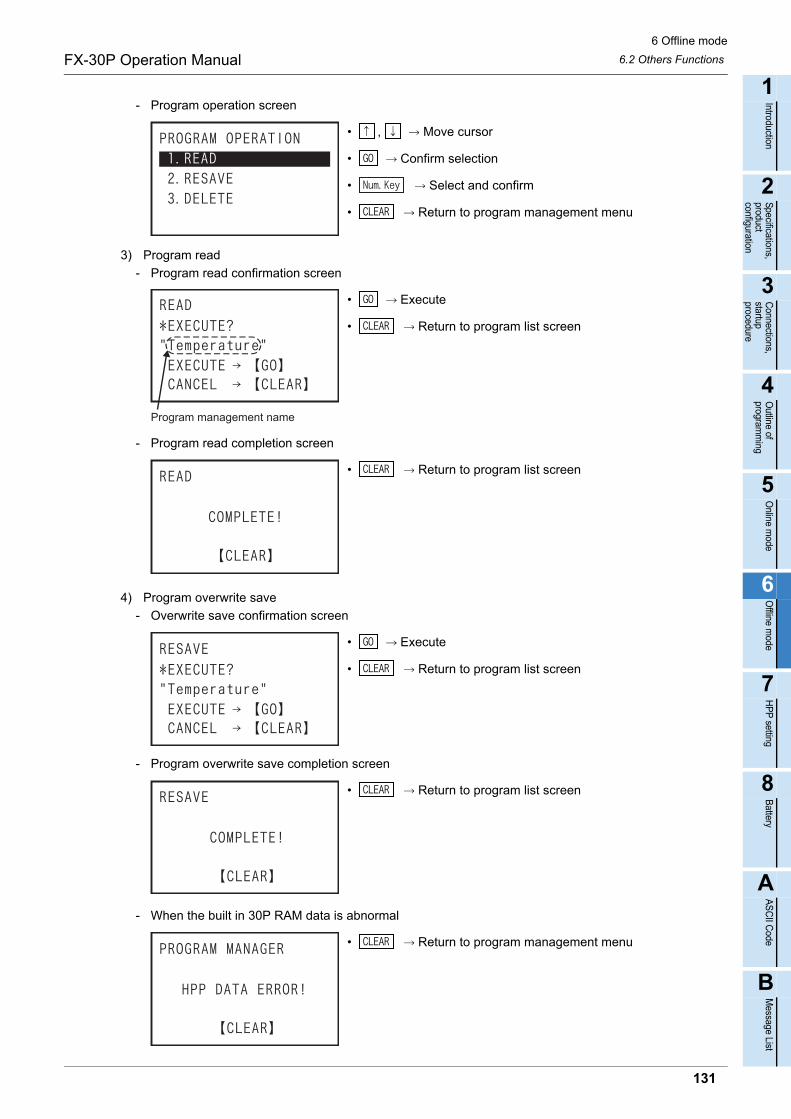
6 Offline mode
6.2 Others FunctionsFX-30P Operation Manual
1
Introduction
2
Specifications,product configuration
3
Connections,
startup procedure
4
Outline of
programm
ing
5
Online m
ode
6
Offline m
ode
7
HP
P setting
8
Battery
A
AS
CII C
ode
B
Message List
- Program operation screen
• , Move cursor
• Confirm selection
• Select and confirm
• Return to program management menu
3) Program read
- Program read confirmation screen
• Execute
• Return to program list screen
- Program read completion screen
• Return to program list screen
4) Program overwrite save
- Overwrite save confirmation screen
• Execute
• Return to program list screen
- Program overwrite save completion screen
• Return to program list screen
- When the built in 30P RAM data is abnormal
• Return to program management menu
Program management name
131

6 Offline mode
6.2 Others FunctionsFX-30P Operation Manual
- When exceeding storage capacity
• Return to program list screen
5) Program delete- Program delete confirmation screen
• Execute
• Return to program list screen
- Program deletion completion screen
• Return to program list screen
6) New save- When exceeding storage capacity
• Return to program management menu
- When the built in 30P RAM data is abnormal
• Return to program management menun
132

6 Offline mode
6.2 Others FunctionsFX-30P Operation Manual
1
Introduction
2
Specifications,product configuration
3
Connections,
startup procedure
4
Outline of
programm
ing
5
Online m
ode
6
Offline m
ode
7
HP
P setting
8
Battery
A
AS
CII C
ode
B
Message List
- New save top screen
• , Move cursor
• Confirm selection
• Return to program management menu
• When "AUTO INPUT" is selected, the 30P automatically specifies program management name("PLC type"_"serial 3 digits"). (Example: FX3U(C)_000)
• When "MANUAL INPUT" is selected, the user must enter the management name.
- Program management name input screen
• When "AUTO INPUT" is selected
• Execute
• Return to program management screen
• When "MANUAL INPUT" is selected
• , Move character cursor (character list in lowest line)
• Select one character (highlighted character in character list in lowest line)
• Delete one character
• Number input
• Confirm program management name
• Return to program management menu
- Up to 18 characters can be entered in ASCII characters (1-byte alphanumerics, 1-byte katakana).- 1-byte katakana can be entered only when "Japanese" is selected in language selection mode.
• When custom input is selected program management name confirmation screen
• Execute
• Return to program management menu
Character list display
Program management name
133

6 Offline mode
6.2 Others FunctionsFX-30P Operation Manual
• Programs new save completion screen
• Return to program management menu
7) All programs deletion
- All programs deletion confirmation screen
• Execute
• Return to program management menu
- All programs deletion completion screen
• Return to program management menu
8) Program management information
- Program management information screen
• Return to program management menu
134
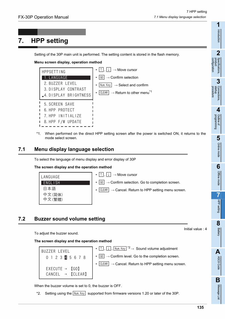
7 HPP setting
7.1 Menu display language selectionFX-30P Operation Manual
1
Introduction
2
Specifications,product configuration
3
Connections,
startup procedure
4
Outline of
programm
ing
5
Online m
ode
6
Offline m
ode
7
HP
P setting
8
Battery
A
AS
CII C
ode
B
Message List
7. HPP setting
Setting of the 30P main unit is performed. The setting content is stored in the flash memory.
Menu screen display, operation method
• , Move cursor
• Confirm selection
• Select and confirm
• Return to other menu*1
*1. When performed on the direct HPP setting screen after the power is switched ON, it returns to themode select screen.
7.1 Menu display language selection
To select the language of menu display and error display of 30P
The screen display and the operation method
• , Move cursor
• Confirm selection. Go to completion screen.
• Cancel. Return to HPP setting menu screen.
7.2 Buzzer sound volume setting
Initial value : 4To adjust the buzzer sound.
The screen display and the operation method
• , , *2 Sound volume adjustment
• Confirm level. Go to the completion screen.
• Cancel. Return to HPP setting menu screen.
When the buzzer volume is set to 0, the buzzer is OFF.
*2. Setting using the supported from firmware versions 1.20 or later of the 30P.
135
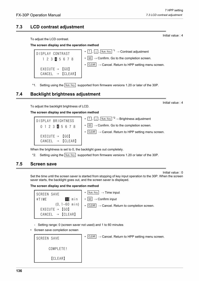
7 HPP setting
7.3 LCD contrast adjustmentFX-30P Operation Manual
7.3 LCD contrast adjustment
Initial value : 4To adjust the LCD contrast.
The screen display and the operation method
• , , *1 Contrast adjustment
• Confirm. Go to the completion screen.
• Cancel. Return to HPP setting menu screen.
*1. Setting using the supported from firmware versions 1.20 or later of the 30P.
7.4 Backlight brightness adjustment
Initial value : 4To adjust the backlight brightness of LCD.
The screen display and the operation method
• , , *2 Brightness adjustment
• Confirm. Go to the completion screen.
• Cancel. Return to HPP setting menu screen.
When the brightness is set to 0, the backlight goes out completely.
*2. Setting using the supported from firmware versions 1.20 or later of the 30P.
7.5 Screen save
Initial value : 0Set the time until the screen saver is started from stopping of key input operation to the 30P. When the screensaver starts, the backlight goes out, and the screen saver is displayed.
The screen display and the operation method
• Time input
• Confirm input
• Cancel. Return to completion screen.
- Setting range: 0 (screen saver not used) and 1 to 60 minutes
• Screen save completion screen
• Cancel. Return to HPP setting menu screen.
136
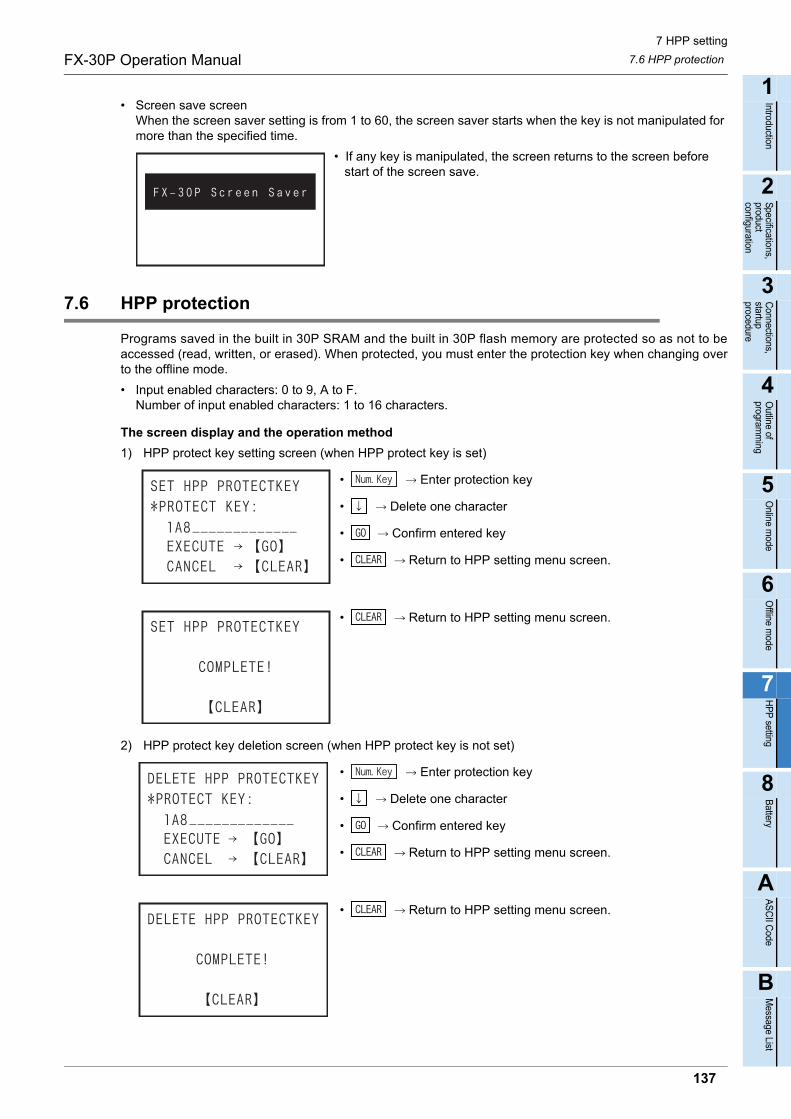
7 HPP setting
7.6 HPP protectionFX-30P Operation Manual
1
Introduction
2
Specifications,product configuration
3
Connections,
startup procedure
4
Outline of
programm
ing
5
Online m
ode
6
Offline m
ode
7
HP
P setting
8
Battery
A
AS
CII C
ode
B
Message List
• Screen save screenWhen the screen saver setting is from 1 to 60, the screen saver starts when the key is not manipulated for more than the specified time.
• If any key is manipulated, the screen returns to the screen before start of the screen save.
7.6 HPP protection
Programs saved in the built in 30P SRAM and the built in 30P flash memory are protected so as not to beaccessed (read, written, or erased). When protected, you must enter the protection key when changing overto the offline mode.
• Input enabled characters: 0 to 9, A to F.Number of input enabled characters: 1 to 16 characters.
The screen display and the operation method
1) HPP protect key setting screen (when HPP protect key is set)
• Enter protection key
• Delete one character
• Confirm entered key
• Return to HPP setting menu screen.
• Return to HPP setting menu screen.
2) HPP protect key deletion screen (when HPP protect key is not set)
• Enter protection key
• Delete one character
• Confirm entered key
• Return to HPP setting menu screen.
• Return to HPP setting menu screen.
137

7 HPP setting
7.7 HPP initializationFX-30P Operation Manual
3) Protection key validation screen
• Enter protection key
• Delete one character
• Confirm entered key
• Return to previous screen
• Go to the next screen
- When protect keys are mismatched
• Return to previous screen
7.7 HPP initialization
The 30P is returned to the initial shipping state (except for F/W). As a result, all of setting values of 30P, andcontents in built in 30P RAM and built in 30P flash memory will be cleared.
The screen display and the operation method
• Execute, switches to top screen when turning on power after completion.
• Cancel. Return to HPP setting menu screen.
• All key inputs disabled
• After completion of HPP initialization, the display automatically switches to the top screen when turning on the power.
• If you forget the HPP protection key, the protection key can be canceled by initializing the HPP. However, all of setting values of HPP, and programs in built in 30P RAM and built in 30P flash memory will be erased.
138

7 HPP setting
7.8 HPP F/W updateFX-30P Operation Manual
1
Introduction
2
Specifications,product configuration
3
Connections,
startup procedure
4
Outline of
programm
ing
5
Online m
ode
6
Offline m
ode
7
HP
P setting
8
Battery
A
AS
CII C
ode
B
Message List
7.8 HPP F/W update
This is to update the F/W by connecting the 30P with a personal computer.For details of the F/W update tool using the personal computer,
refer to the FX-30P F/W UPDATE TOOL operation manual.
The screen display and the operation method
• Execute update
• Return to HPP setting menu screen.
• Return to HPP setting menu screen.
• All key inputs disabled
• During communication, all key inputs are disabled.
• When F/W updating is completed, the 30P is reset, and the display is switched to the top screen when turning the power on.
- For setting the 30P to the HPP F/W update standby status, the following method is available (in 30Ps whose manufacturer's serial number is 950000 or later) in addition to the method above of displaying the HPP F/W UPDATE screen.
HPP F/W update standby status setting method
1) Turn the power of the 30P OFF.
2) Turn the power of the 30P ON while pressing and holding the and keys at the same time.
3) The 30P starts up, the following screen appears, and the 30P enters the F/W update standby status.
• For resetting the F/W update standby status, turn the power of the 30P OFF once, and then turn it ON again.
139

8 Battery
8.1 Battery HandlingFX-30P Operation Manual
8. Battery
The 30P incorporates a battery (equivalent to FX3U-32BL).When the battery voltage declines, the 30P battery voltage drop error appears (the message "Battery voltagedrop!" is displayed when the power source is turned ON). In this case, replace the battery FX3U-32BL.
8.1 Battery Handling
• Precautions for battery transportationRefer to Appendix F.
• Battery handling for EU countriesRefer to Appendix G.
• For battery handling in California, U.S.A.
8.2 Battery specifications, Battery life
8.2.1 Differences between FX-30P’s internal battery and the optional battery
Although the optional battery (FX3U-32BL) serves as the same as the 30P’s internal battery, they differ in theways described below.They may also have different external colors due to dates of manufacture.
MAINTENANCE PRECAUTIONS
• Turn off the power to the PLC before attaching or detaching the battery.Doing so may cause equipment failures, or malfunctions.
• Use the battery for memory backup correctly in conformance to this manual.- Use the battery only for the specified purpose.- Connect the battery correctly.- Do not charge, disassemble, heat, put in fire, short-circuit, connect reversely, weld, swallow or burn the battery, or apply
excessive forces (vibration, impact, drop, etc.) to the battery.- Do not store or use the battery at high temperatures or expose to direct sunlight.- Do not expose to water, bring near fire or touch liquid leakage or other contents directly.- Incorrect handling of the battery may cause heat excessive generation, bursting, ignition, liquid leakage or deformation, and lead
to injury, fire or failures and malfunctions of facilities and other equipment.
TRANSPORT AND STORAGE PRECAUTIONS
• Before transporting the FX-30P, make sure to turn on the power of the FX-30P, and confirm that an HPP low battery voltage errordoes not occur (or confirm that the HPP battery voltage is 2.7 V or more). If the FX-30P is transported when the battery voltage is low and the battery life is expired, the battery-backed data may not be heldcorrectly during transportation.
• When transporting lithium batteries, follow required transportation regulations.(For details of the regulated products, refer to Appendix F)
Item Specifications Remark
Nominal voltage 3V The battery voltage can be inspected from the HELP screen in the offline mode.
Regarding California U.S.A. law,Perchlorate Material - special handling may apply,See http://www.dtsc.ca.gov/hazardouswaste/perchlorate/
140
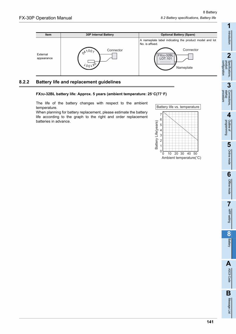
8 Battery
8.2 Battery specifications, Battery lifeFX-30P Operation Manual
1
Introduction
2
Specifications,product configuration
3
Connections,
startup procedure
4
Outline of
programm
ing
5
Online m
ode
6
Offline m
ode
7
HP
P setting
8
Battery
A
AS
CII C
ode
B
Message List
8.2.2 Battery life and replacement guidelines
FX3U-32BL battery life: Approx. 5 years (ambient temperature: 25 C(77 F)
The life of the battery changes with respect to the ambienttemperature.When planning for battery replacement, please estimate the batterylife according to the graph to the right and order replacementbatteries in advance.
Item 30P Internal Battery Optional Battery (Spare)
Externalappearance
A nameplate label indicating the product model and lotNo. is affixed.
Connector041001
041001
Connector
FX3U-32BLLOT.101
Nameplate
............
7
0 10 4020 30 500
1
6
5
4
3
2
Bat
tery
Life
(yea
rs)
Ambient temperature( C)
Battery life vs. temperature
141
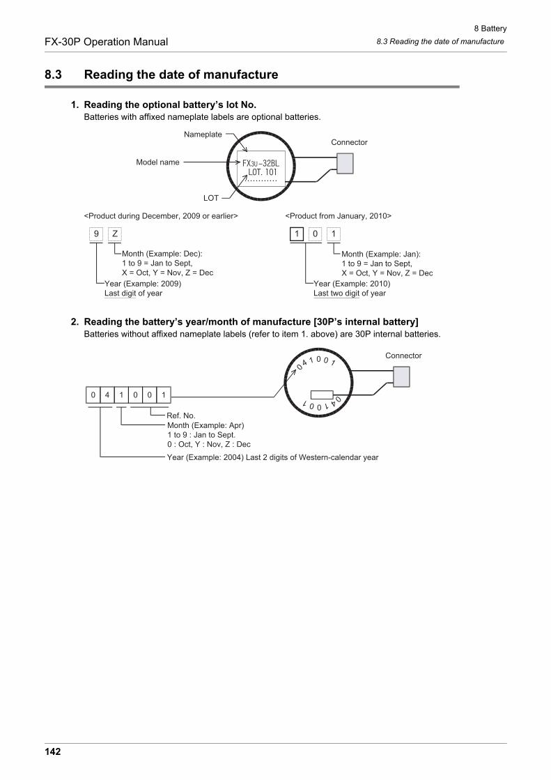
8 Battery
8.3 Reading the date of manufactureFX-30P Operation Manual
8.3 Reading the date of manufacture
1. Reading the optional battery’s lot No.Batteries with affixed nameplate labels are optional batteries.
2. Reading the battery’s year/month of manufacture [30P’s internal battery]Batteries without affixed nameplate labels (refer to item 1. above) are 30P internal batteries.
<Product during December, 2009 or earlier>
9 Z 1 0 1
Year (Example: 2010)Last two digit of year
Month (Example: Jan):1 to 9 = Jan to Sept,X = Oct, Y = Nov, Z = Dec
Year (Example: 2009)Last digit of year
<Product from January, 2010>
Month (Example: Dec):1 to 9 = Jan to Sept,X = Oct, Y = Nov, Z = Dec
ConnectorNameplate
Model name
LOT
04 1 0 0 1
041001
Connector
0 4 1 0 0 1
Ref. No.
Year (Example: 2004) Last 2 digits of Western-calendar year
Month (Example: Apr)1 to 9 : Jan to Sept.0 : Oct, Y : Nov, Z : Dec
142

8 Battery
8.4 Battery ReplacementFX-30P Operation Manual
1
Introduction
2
Specifications,product configuration
3
Connections,
startup procedure
4
Outline of
programm
ing
5
Online m
ode
6
Offline m
ode
7
HP
P setting
8
Battery
A
AS
CII C
ode
B
Message List
8.4 Battery Replacement
1 Turn OFF the power source. (Disconnect the connection cable between the PLC and per-sonal computer.)Caution
When data is saved in the built in 30P RAM, transfer to flash memory before battery exchange.(For the transfer method, refer to Subsection 6.2.8 program management)
2 Remove the battery cover screw.
Remove the battery cover screw "A" by using a screwdriver.
3 Detach the battery cover.
Detach the battery cover by inserting slotted screwdriverinto the lower side of the battery cover "B", and then push-ing down.
4 Remove the old battery.
Extract the old battery from the battery holder ("C"), and dis-connect the battery connector ("D").
5 Install the new battery.
Connect the battery connector ("D") to the new battery, andinsert the battery into the battery holder ("C").
6 Put on battery cover.
Fit in the upper side of battery cover "B" first, then push inthe lower side to attach the cover.
7 Secure the battery cover with the battery cover screw.
Secure the battery cover screw "A" by using a screwdriver.
Caution
After exchanging the batteries, make sure the battery voltage is 3V or more by monitoring the HELP screen in offline mode.
A
B
D
CBattery
143

8 Battery
8.4 Battery ReplacementFX-30P Operation Manual
MEMO
144
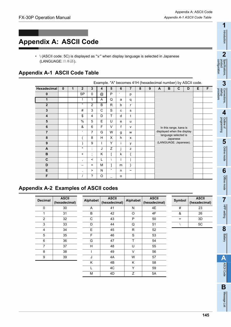
Appendix A: ASCII Code
Appendix A-1 ASCII Code TableFX-30P Operation Manual
1
Introduction
2
Specifications,product configuration
3
Connections,
startup procedure
4
Outline of
programm
ing
5
Online m
ode
6
Offline m
ode
7
HP
P setting
8
Battery
A
AS
CII C
ode
B
Message List
Appendix A: ASCII Code
• \ (ASCII code: 5C) is displayed as " " when display language is selected in Japanese (LANGUAGE: ).
Appendix A-1 ASCII Code Table
Example. "A" becomes 41H (hexadecimal number) by ASCII code.
Appendix A-2 Examples of ASCII codes
Hexadecimal 0 1 2 3 4 5 6 7 8 9 A B C D E F
0 SP 0 @ P ´ p
In this range, kana is displayed when the display
language selected is Japanese
(LANGUAGE: Japanese).
1 ! 1 A Q a q
2 ” 2 B R b r
3 # 3 C S c s
4 $ 4 D T d t
5 % 5 E U e u
6 & 6 F V f v
7 ’ 7 G W g w
8 ( 8 H X h x
9 ) 9 I Y i y
A * : J Z j z
B + ; K [ k {
C , < L \ l |
D – = M ] m }
E . > N ˆ n ~
F / ? O _ o
DecimalASCII
(hexadecimal)Alphabet
ASCII (hexadecimal)
AlphabetASCII
(hexadecimal)Symbol
ASCII (hexadecimal)
0 30 A 41 N 4E # 23
1 31 B 42 O 4F & 26
2 32 C 43 P 50 = 3D
3 33 D 44 Q 51 \ 5C
4 34 E 45 R 52
5 35 F 46 S 53
6 36 G 47 T 54
7 37 H 48 U 55
8 38 I 49 V 56
9 39 J 4A W 57
K 4B K 58
L 4C Y 59
M 4D Z 5A
145
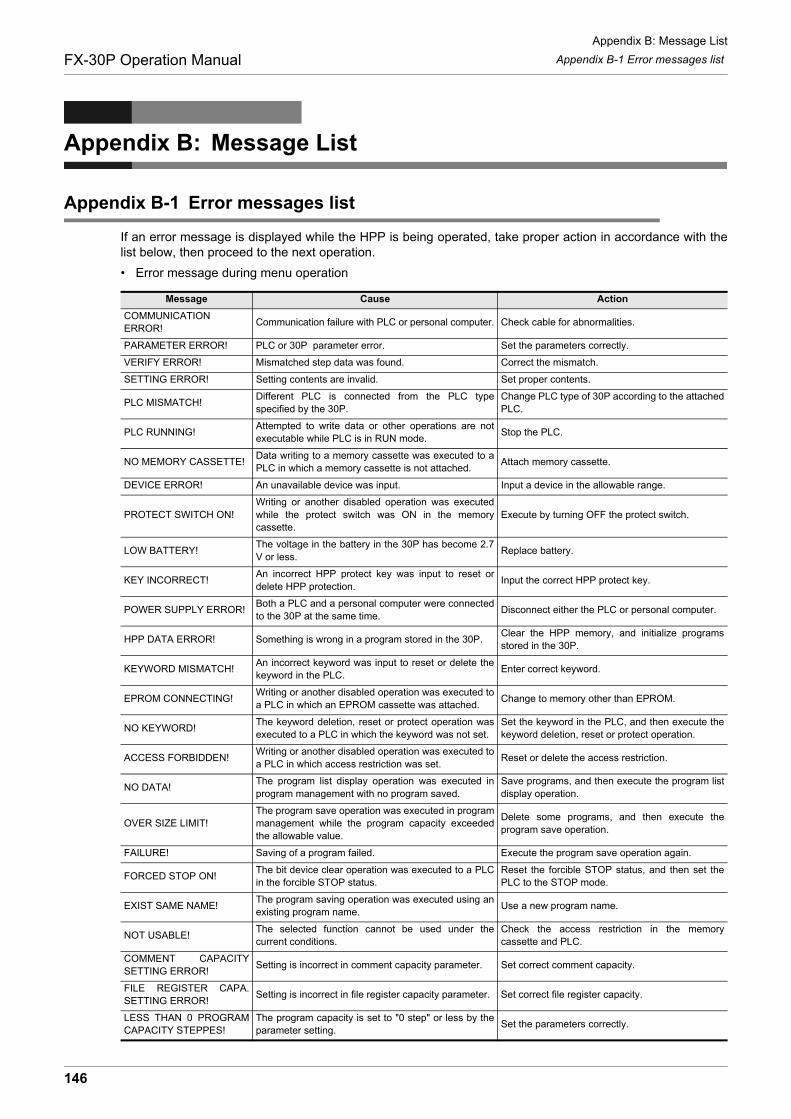
Appendix B: Message List
Appendix B-1 Error messages listFX-30P Operation Manual
Appendix B: Message List
Appendix B-1 Error messages list
If an error message is displayed while the HPP is being operated, take proper action in accordance with thelist below, then proceed to the next operation.
• Error message during menu operation
Message Cause Action
COMMUNICATIONERROR!
Communication failure with PLC or personal computer. Check cable for abnormalities.
PARAMETER ERROR! PLC or 30P parameter error. Set the parameters correctly.
VERIFY ERROR! Mismatched step data was found. Correct the mismatch.
SETTING ERROR! Setting contents are invalid. Set proper contents.
PLC MISMATCH!Different PLC is connected from the PLC typespecified by the 30P.
Change PLC type of 30P according to the attachedPLC.
PLC RUNNING!Attempted to write data or other operations are notexecutable while PLC is in RUN mode.
Stop the PLC.
NO MEMORY CASSETTE!Data writing to a memory cassette was executed to aPLC in which a memory cassette is not attached.
Attach memory cassette.
DEVICE ERROR! An unavailable device was input. Input a device in the allowable range.
PROTECT SWITCH ON!Writing or another disabled operation was executedwhile the protect switch was ON in the memorycassette.
Execute by turning OFF the protect switch.
LOW BATTERY!The voltage in the battery in the 30P has become 2.7V or less.
Replace battery.
KEY INCORRECT!An incorrect HPP protect key was input to reset ordelete HPP protection.
Input the correct HPP protect key.
POWER SUPPLY ERROR!Both a PLC and a personal computer were connectedto the 30P at the same time.
Disconnect either the PLC or personal computer.
HPP DATA ERROR! Something is wrong in a program stored in the 30P. Clear the HPP memory, and initialize programsstored in the 30P.
KEYWORD MISMATCH!An incorrect keyword was input to reset or delete thekeyword in the PLC.
Enter correct keyword.
EPROM CONNECTING!Writing or another disabled operation was executed toa PLC in which an EPROM cassette was attached.
Change to memory other than EPROM.
NO KEYWORD!The keyword deletion, reset or protect operation wasexecuted to a PLC in which the keyword was not set.
Set the keyword in the PLC, and then execute thekeyword deletion, reset or protect operation.
ACCESS FORBIDDEN!Writing or another disabled operation was executed toa PLC in which access restriction was set.
Reset or delete the access restriction.
NO DATA!The program list display operation was executed inprogram management with no program saved.
Save programs, and then execute the program listdisplay operation.
OVER SIZE LIMIT!The program save operation was executed in programmanagement while the program capacity exceededthe allowable value.
Delete some programs, and then execute theprogram save operation.
FAILURE! Saving of a program failed. Execute the program save operation again.
FORCED STOP ON!The bit device clear operation was executed to a PLCin the forcible STOP status.
Reset the forcible STOP status, and then set thePLC to the STOP mode.
EXIST SAME NAME!The program saving operation was executed using anexisting program name.
Use a new program name.
NOT USABLE!The selected function cannot be used under thecurrent conditions.
Check the access restriction in the memorycassette and PLC.
COMMENT CAPACITYSETTING ERROR!
Setting is incorrect in comment capacity parameter. Set correct comment capacity.
FILE REGISTER CAPA.SETTING ERROR!
Setting is incorrect in file register capacity parameter. Set correct file register capacity.
LESS THAN 0 PROGRAMCAPACITY STEPPES!
The program capacity is set to "0 step" or less by theparameter setting.
Set the parameters correctly.
146

Appendix B: Message List
Appendix B-1 Error messages listFX-30P Operation Manual
1
Introduction
2
Specifications,product configuration
3
Connections,
startup procedure
4
Outline of
programm
ing
5
Online m
ode
6
Offline m
ode
7
HP
P setting
8
Battery
A
AS
CII C
ode
B
Message List
• Error messages displayed during program operation
LATCH RANGE SETTINGERROR!
Setting is incorrect in latch range parameter. Set correct latch range.
INPUT ERROR! Invalid keyword is entered in keyword registration. Enter correct keyword.
Message Cause Action
COMMUNICATION ERROR Communication failure with PLC. Check cable for abnormality.
PLC RUNNINGAttempted to write data or other operations are notexecutable while PLC is in RUN mode.
Stop the PLC.
SETTING ERROR Mismatched step data was found. Set proper contents.
NOT USABLE The selected function cannot be used under thecurrent conditions.
Check the access restriction in the memorycassette and PLC.
WRITE FORBIDDEN
Writing or another disabled operation was executed toa PLC in which an EPROM cassette or a cassette withthe protect switch ON was attached or the accessrestriction was set.
Check the access restriction in the memorycassette and PLC.
NO PROGRAM SPACE There is no more available program storage area.Change the parameter setting so that the programstorage area becomes "1 step" or more.
STEP OVERFLOWThe specified step number is larger than the programsize.
Specify a step number within the program size.
DEVICE ERROR An unavailable device was input. Input an available device.
INSTR. ERROR An unavailable instruction was input. Input an available instruction.
VERIFY ERROR Mismatched step data was found. Correct the mismatch.
Message Cause Action
147

Appendix B: Message List
Appendix B-2 Error messages displayed during PLC diagnostic/program checkFX-30P Operation Manual
Appendix B-2 Error messages displayed during PLC diagnostic/program check
When a program error occurs in the PLC, the error code is stored in special data registers D8060 - D8067,D8438, D8449, D8487 and D8489. The following actions should be followed for diagnostic errors.
Appendix B-2-1 For FX3S/FX3G/FX3GC/FX3U/FX3UC PLCs
Error code
PLC operation at error occurrence
Contents of error Action
I/O configuration error [M8060(D8060)]
Ex-ample: 1020
Continuesoperation
The head number of unconnected I/O device
• 1st to 3rd digits: Device numberFX3G/FX3GC:10 to 177FX3U/FX3UC:10 to 337
• 4th digit: I/O type(1 = input (X), 0 = output (Y))
Example: When 1020 is stored in D8060Inputs X020 and later are unconnected.
Unconnected I/O relay numbers are programmed.The PLC continues its operation. Modify the program,check wiring connection, or add the appropriate unit/block.
Serial communication error 2 [M8438 (D8438)]
0000 - No error
3801
Continuesoperation
Parity, overrun or framing error
• Ethernet communication, inverter communication, computer link and programming:Ensure the parameters are correctly set according to their applications.
• N:N network, parallel link, MODBUS communication,etc.:Check programs according to applications.
• Remote maintenance:Ensure modem power is ON and check the settings ofthe AT commands.
• Wiring:Check the communication cables for correct wiring.
3802 Communication character error
3803 Communication data sum check error
3804 Communication data format error
3805 Command error
3806 Communication time-out detected
3807 Modem initialization error
3808 N:N network parameter error
3809 N:N Network setting error
3812 Parallel link character error
3813 Parallel link sum error
3814 Parallel link format error
3820 Inverter communication error
3821 MODBUS communication error
3830 Memory access error
When the memory cassette is used, check whether it ismounted correctly.If the problem persists or if the memory cassette is notused, something may be malfunctioning inside the PLC. Consult your local Mitsubishi Electric representative.
3840 Special adapter connection error Check connection of the special adapter.
PLC hardware error [M8061(D8061)]
0000 - No error
6101
Stopsoperation
Memory access error
When the memory cassette is used, check whether it ismounted correctly.If the problem persists or if the memory cassette is notused, something may be malfunctioning inside the PLC.Consult your local Mitsubishi Electric representative.
6102 Operation circuit error
Isolate the PLC and supply power to it using a differentpower supply.If the ERROR(ERR) LED turns OFF, noise may beaffecting the PLC. Take the following measures.
- Check the ground wiring, and reexamine the wiring route and installation location.
- Fit a noise filter onto the power supply line.If the ERROR(ERR) LED does not turn OFF even afterthe above actions are taken, consult your local MitsubishiElectric representative.
1 0 2 0
1: Input (X), 0: Output (Y)
Device number
Example: When X020 is unconnected
BCD conversion value
148
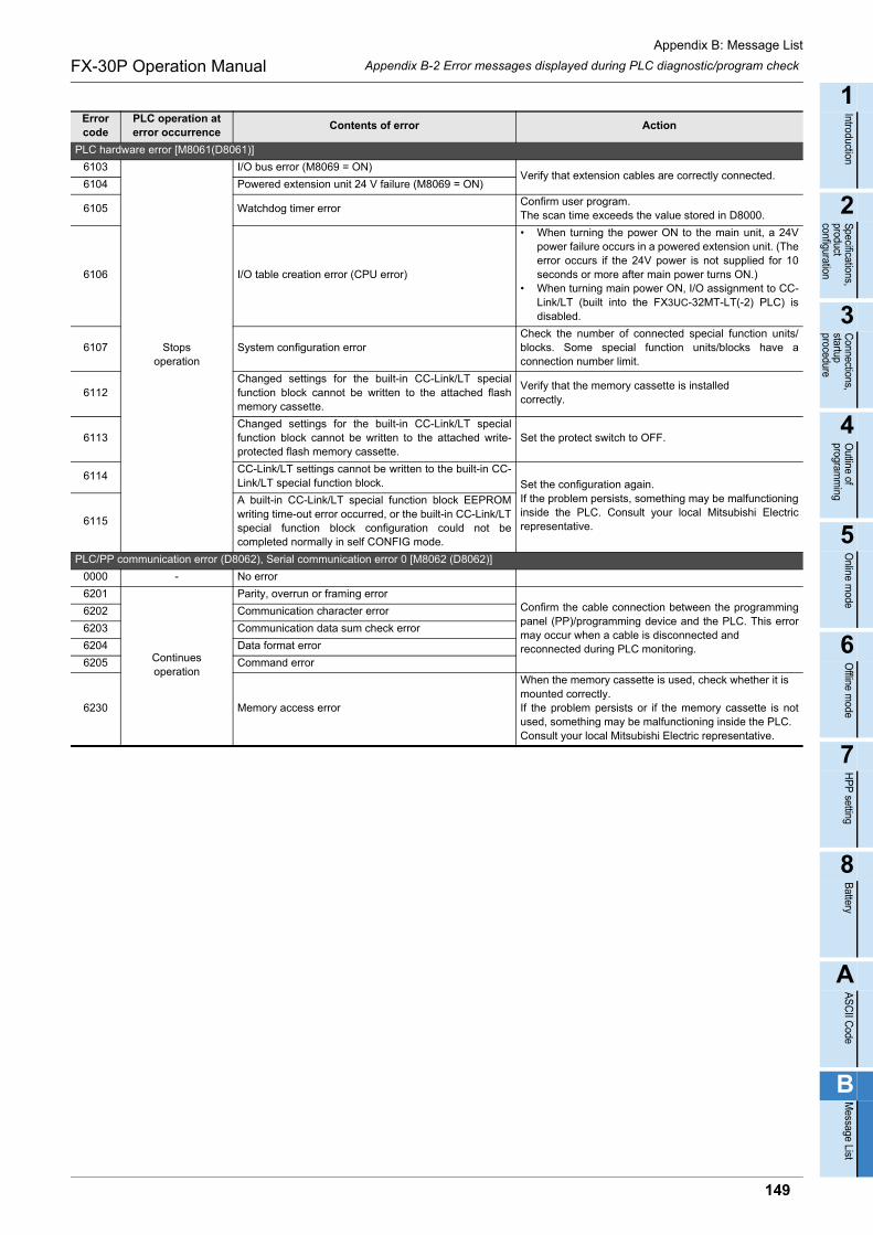
Appendix B: Message List
Appendix B-2 Error messages displayed during PLC diagnostic/program checkFX-30P Operation Manual
1
Introduction
2
Specifications,product configuration
3
Connections,
startup procedure
4
Outline of
programm
ing
5
Online m
ode
6
Offline m
ode
7
HP
P setting
8
Battery
A
AS
CII C
ode
B
Message List
PLC hardware error [M8061(D8061)]
6103
Stopsoperation
I/O bus error (M8069 = ON)Verify that extension cables are correctly connected.
6104 Powered extension unit 24 V failure (M8069 = ON)
6105 Watchdog timer errorConfirm user program.The scan time exceeds the value stored in D8000.
6106 I/O table creation error (CPU error)
• When turning the power ON to the main unit, a 24Vpower failure occurs in a powered extension unit. (Theerror occurs if the 24V power is not supplied for 10seconds or more after main power turns ON.)
• When turning main power ON, I/O assignment to CC-Link/LT (built into the FX3UC-32MT-LT(-2) PLC) isdisabled.
6107 System configuration errorCheck the number of connected special function units/blocks. Some special function units/blocks have aconnection number limit.
6112Changed settings for the built-in CC-Link/LT specialfunction block cannot be written to the attached flashmemory cassette.
Verify that the memory cassette is installed correctly.
6113Changed settings for the built-in CC-Link/LT specialfunction block cannot be written to the attached write-protected flash memory cassette.
Set the protect switch to OFF.
6114CC-Link/LT settings cannot be written to the built-in CC-Link/LT special function block. Set the configuration again.
If the problem persists, something may be malfunctioninginside the PLC. Consult your local Mitsubishi Electricrepresentative.6115
A built-in CC-Link/LT special function block EEPROMwriting time-out error occurred, or the built-in CC-Link/LTspecial function block configuration could not becompleted normally in self CONFIG mode.
PLC/PP communication error (D8062), Serial communication error 0 [M8062 (D8062)]
0000 - No error
6201
Continues operation
Parity, overrun or framing errorConfirm the cable connection between the programmingpanel (PP)/programming device and the PLC. This errormay occur when a cable is disconnected and reconnected during PLC monitoring.
6202 Communication character error
6203 Communication data sum check error
6204 Data format error
6205 Command error
6230 Memory access error
When the memory cassette is used, check whether it ismounted correctly.If the problem persists or if the memory cassette is notused, something may be malfunctioning inside the PLC. Consult your local Mitsubishi Electric representative.
Error code
PLC operation at error occurrence
Contents of error Action
149
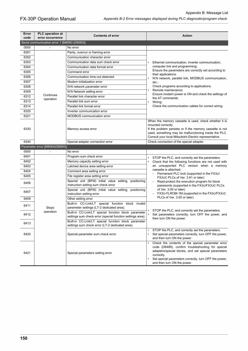
Appendix B: Message List
Appendix B-2 Error messages displayed during PLC diagnostic/program checkFX-30P Operation Manual
Serial communication error 1 [M8063 (D8063)]
0000 - No error
6301
Continuesoperation
Parity, overrun or framing error
• Ethernet communication, inverter communication, computer link and programming:Ensure the parameters are correctly set according to their applications.
• N:N network, parallel link, MODBUS communication,etc.:Check programs according to applications.
• Remote maintenance:Ensure modem power is ON and check the settings ofthe AT commands.
• Wiring:Check the communication cables for correct wiring.
6302 Communication character error
6303 Communication data sum check error
6304 Communication data format error
6305 Command error
6306 Communication time-out detected
6307 Modem initialization error
6308 N:N network parameter error
6309 N:N Network setting error
6312 Parallel link character error
6313 Parallel link sum error
6314 Parallel link format error
6320 Inverter communication error
6321 MODBUS communication error
6330 Memory access error
When the memory cassette is used, check whether it ismounted correctly.If the problem persists or if the memory cassette is notused, something may be malfunctioning inside the PLC.Consult your local Mitsubishi Electric representative.
6340 Special adapter connection error Check connection of the special adapter.
Parameter error [M8064(D8064)]
0000 - No error
6401
Stopsoperation
Program sum check error • STOP the PLC, and correctly set the parameters.• Check that the following functions are not used with
an unsupported PLC version when a memorycassette is attached:- Permanent PLC lock (supported in the FX3U/
FX3UC PLCs of Ver. 2.61 or later)- Read-protect the execution program for block
passwords (supported in the FX3U/FX3UC PLCs of Ver. 3.00 or later)
- FX3U-FLROM-1M (supported in the FX3U/FX3UC PLCs of Ver. 3.00 or later)
6402 Memory capacity setting error
6403 Latched device area setting error
6404 Comment area setting error
6405 File register area setting error
6406Special unit (BFM) initial value setting, positioninginstruction setting sum check error
6407Special unit (BFM) initial value setting, positioninginstruction setting error
6409 Other setting error
6411Built-in CC-Link/LT special function block invalidparameter settings (LT-2 dedicated area).
• STOP the PLC, and correctly set the parameters.• Set parameters correctly, turn OFF the power, and
then turn ON the power.6412
Built-in CC-Link/LT special function block parametersettings sum check error (special function settings area).
6413Built-in CC-Link/LT special function block parametersettings sum check error (LT-2 dedicated area).
6420 Special parameter sum check error• STOP the PLC, and correctly set the parameters.• Set special parameters correctly, turn OFF the power,
and then turn ON the power.
6421 Special parameters setting error
• Check the contents of the special parameter errorcode (D8489), confirm troubleshooting for specialadapters/special blocks, and set special parameterscorrectly.
• Set special parameters correctly, turn OFF the power,and then turn ON the power.
Error code
PLC operation at error occurrence
Contents of error Action
150
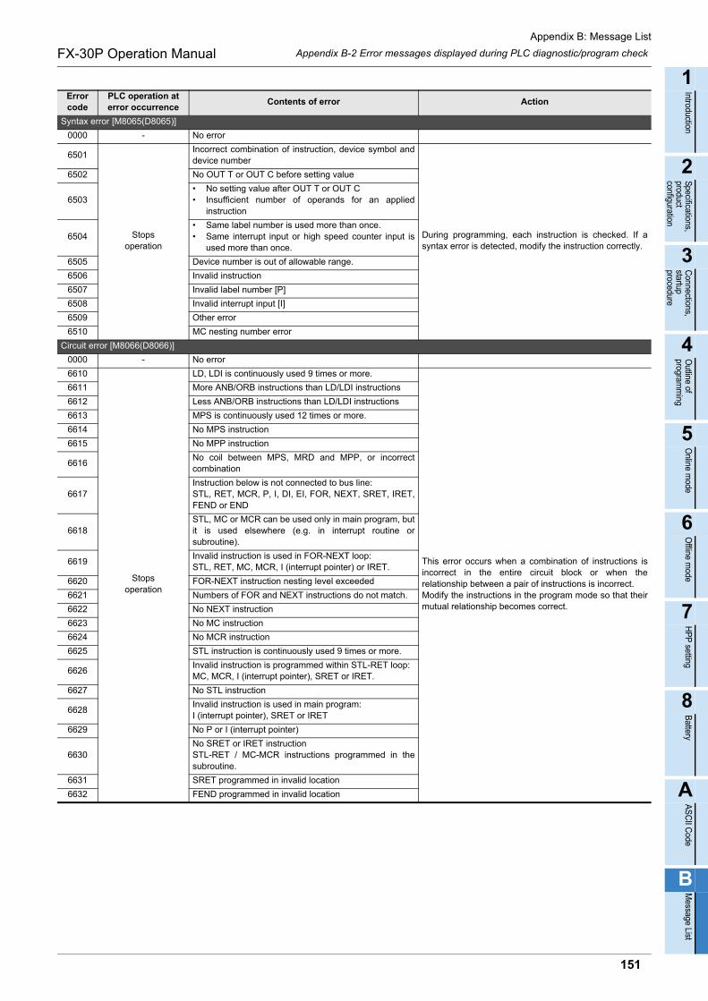
Appendix B: Message List
Appendix B-2 Error messages displayed during PLC diagnostic/program checkFX-30P Operation Manual
1
Introduction
2
Specifications,product configuration
3
Connections,
startup procedure
4
Outline of
programm
ing
5
Online m
ode
6
Offline m
ode
7
HP
P setting
8
Battery
A
AS
CII C
ode
B
Message List
Syntax error [M8065(D8065)]
0000 - No error
6501
Stopsoperation
Incorrect combination of instruction, device symbol anddevice number
During programming, each instruction is checked. If asyntax error is detected, modify the instruction correctly.
6502 No OUT T or OUT C before setting value
6503• No setting value after OUT T or OUT C• Insufficient number of operands for an applied
instruction
6504• Same label number is used more than once.• Same interrupt input or high speed counter input is
used more than once.
6505 Device number is out of allowable range.
6506 Invalid instruction
6507 Invalid label number [P]
6508 Invalid interrupt input [I]
6509 Other error
6510 MC nesting number error
Circuit error [M8066(D8066)]
0000 - No error
6610
Stopsoperation
LD, LDI is continuously used 9 times or more.
This error occurs when a combination of instructions isincorrect in the entire circuit block or when therelationship between a pair of instructions is incorrect.Modify the instructions in the program mode so that theirmutual relationship becomes correct.
6611 More ANB/ORB instructions than LD/LDI instructions
6612 Less ANB/ORB instructions than LD/LDI instructions
6613 MPS is continuously used 12 times or more.
6614 No MPS instruction
6615 No MPP instruction
6616No coil between MPS, MRD and MPP, or incorrectcombination
6617Instruction below is not connected to bus line: STL, RET, MCR, P, I, DI, EI, FOR, NEXT, SRET, IRET,FEND or END
6618STL, MC or MCR can be used only in main program, butit is used elsewhere (e.g. in interrupt routine orsubroutine).
6619Invalid instruction is used in FOR-NEXT loop: STL, RET, MC, MCR, I (interrupt pointer) or IRET.
6620 FOR-NEXT instruction nesting level exceeded
6621 Numbers of FOR and NEXT instructions do not match.
6622 No NEXT instruction
6623 No MC instruction
6624 No MCR instruction
6625 STL instruction is continuously used 9 times or more.
6626Invalid instruction is programmed within STL-RET loop: MC, MCR, I (interrupt pointer), SRET or IRET.
6627 No STL instruction
6628Invalid instruction is used in main program: I (interrupt pointer), SRET or IRET
6629 No P or I (interrupt pointer)
6630No SRET or IRET instructionSTL-RET / MC-MCR instructions programmed in thesubroutine.
6631 SRET programmed in invalid location
6632 FEND programmed in invalid location
Error code
PLC operation at error occurrence
Contents of error Action
151
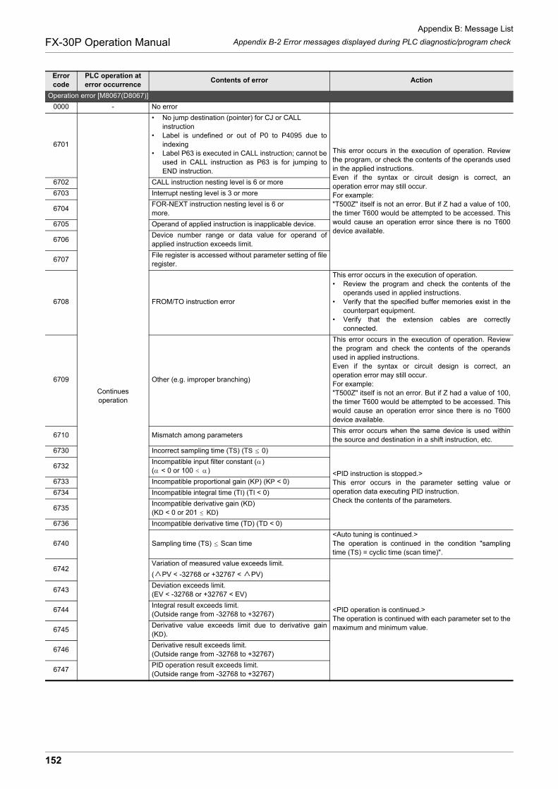
Appendix B: Message List
Appendix B-2 Error messages displayed during PLC diagnostic/program checkFX-30P Operation Manual
Operation error [M8067(D8067)]
0000 - No error
6701
Continuesoperation
• No jump destination (pointer) for CJ or CALL instruction
• Label is undefined or out of P0 to P4095 due toindexing
• Label P63 is executed in CALL instruction; cannot beused in CALL instruction as P63 is for jumping toEND instruction.
This error occurs in the execution of operation. Reviewthe program, or check the contents of the operands usedin the applied instructions.Even if the syntax or circuit design is correct, anoperation error may still occur.For example:"T500Z" itself is not an error. But if Z had a value of 100,the timer T600 would be attempted to be accessed. Thiswould cause an operation error since there is no T600device available.
6702 CALL instruction nesting level is 6 or more
6703 Interrupt nesting level is 3 or more
6704FOR-NEXT instruction nesting level is 6 or more.
6705 Operand of applied instruction is inapplicable device.
6706Device number range or data value for operand ofapplied instruction exceeds limit.
6707File register is accessed without parameter setting of fileregister.
6708 FROM/TO instruction error
This error occurs in the execution of operation.• Review the program and check the contents of the
operands used in applied instructions.• Verify that the specified buffer memories exist in the
counterpart equipment.• Verify that the extension cables are correctly
connected.
6709 Other (e.g. improper branching)
This error occurs in the execution of operation. Reviewthe program and check the contents of the operandsused in applied instructions.Even if the syntax or circuit design is correct, anoperation error may still occur.For example:"T500Z" itself is not an error. But if Z had a value of 100,the timer T600 would be attempted to be accessed. Thiswould cause an operation error since there is no T600device available.
6710 Mismatch among parametersThis error occurs when the same device is used withinthe source and destination in a shift instruction, etc.
6730 Incorrect sampling time (TS) (TS 0)
<PID instruction is stopped.>This error occurs in the parameter setting value oroperation data executing PID instruction.Check the contents of the parameters.
6732Incompatible input filter constant ( )( < 0 or 100 )
6733 Incompatible proportional gain (KP) (KP < 0)
6734 Incompatible integral time (TI) (TI < 0)
6735Incompatible derivative gain (KD)(KD < 0 or 201 KD)
6736 Incompatible derivative time (TD) (TD < 0)
6740 Sampling time (TS) Scan time<Auto tuning is continued.>The operation is continued in the condition "samplingtime (TS) = cyclic time (scan time)".
6742Variation of measured value exceeds limit.
( PV < -32768 or +32767 < PV)
<PID operation is continued.>The operation is continued with each parameter set to themaximum and minimum value.
6743Deviation exceeds limit.(EV < -32768 or +32767 < EV)
6744Integral result exceeds limit.(Outside range from -32768 to +32767)
6745Derivative value exceeds limit due to derivative gain(KD).
6746Derivative result exceeds limit.(Outside range from -32768 to +32767)
6747PID operation result exceeds limit.(Outside range from -32768 to +32767)
Error code
PLC operation at error occurrence
Contents of error Action
152

Appendix B: Message List
Appendix B-2 Error messages displayed during PLC diagnostic/program checkFX-30P Operation Manual
1
Introduction
2
Specifications,product configuration
3
Connections,
startup procedure
4
Outline of
programm
ing
5
Online m
ode
6
Offline m
ode
7
HP
P setting
8
Battery
A
AS
CII C
ode
B
Message List
Operation error [M8067(D8067)]
6748
Continuesoperation
PID output upper limit set value < PID output lower limitset value.
<Transpose of output upper limit value and output lower
limit value. PID operation is continued.>Verify that the target setting contents are correct.
6749Abnormal PID input variation alarm set value or outputvariation alarm set value (Set value < 0)
<Alarm output is not given. PID operation iscontinued.>Verify that the target setting contents are correct.
6750<Step response method>Improper auto tuning result
<Auto tuning is finished. PID operation is started.>• The deviation at start of auto tuning is 150 or less. • The deviation at end of auto tuning is 1/3 or more of
the deviation at start of auto tuning. Check the measured value and target value, and thenexecute auto tuning again.
6751<Step response method>Auto tuning operation direction mismatch
<Auto tuning is forcibly finished. PID operation is notstarted.>The operation direction estimated from the measuredvalue at the start of auto tuning was different from theactual operation direction of the output during autotuning.Correct the relationship among the target value, outputvalue for auto tuning, and the measured value, and thenexecute auto tuning again.
6752<Step response method>Improper auto tuning operation
<Auto tuning is finished. PID operation is not started.>Because the set value was fluctuated during auto tuning,auto tuning was not executed correctly.Set the sampling time to a value larger than the outputchange cycle, or set a larger value for the input filterconstant.After changing the setting, execute auto tuning again.
6753<Limit cycle method>Abnormal output set value for auto tuning[ULV (upper limit) LLV (lower limit)] <Auto tuning is forcibly finished. PID operation is not
started.>Check whether the target setting contents are correct.
6754<Limit cycle method>Abnormal PV threshold (hysteresis) set value for autotuning (SHPV < 0)
6755
<Limit cycle method>Abnormal auto tuning transfer status(Data of device controlling transfer status is abnormallyoverwritten.)
<Auto tuning is forcibly finished. PID operation is notstarted.>Ensure that devices occupied by PID instruction are notoverwritten in the program.
6756<Limit cycle method>Abnormal result due to excessive auto tuningmeasurement time ( on > , on < 0, < 0)
<Auto tuning is forcibly finished. PID operation is notstarted.>The auto tuning time is longer than necessary.Increase the difference (ULV - LLV) between the upperlimit and lower limit of the output value for auto tuning, seta smaller value to the input filter constant ( ), or set asmaller value to the PV threshold (SHPV) for auto tuning,and then check the result for improvement.
6757<Limit cycle method>Auto tuning result exceeds proportional gain. (KP= outside range from 0 to 32767)
<Auto tuning is finished (KP = 32767). PID operationis started.>The variation of the measured value (PV) is smallcompared with the output value. Multiply the measuredvalue (PV) by "10" so that the variation of the measuredvalue will increase during auto tuning.
6758<Limit cycle method>Auto tuning result exceeds integral time.(TI = outside range from 0 to 32767)
<Auto tuning is finished (KP = 32767). PID operationis started.>The auto tuning time is longer than necessary.Increase the difference (ULV - LLV) between the upperlimit and lower limit of the output value for auto tuning, seta smaller value to the input filter constant ( ), or set asmaller value to the PV threshold (SHPV) for auto tuning,and then check the result for improvement.
6759<Limit cycle method>Auto tuning result exceeds derivative time.(TD = outside range from 0 to 32767)
6760 ABS data read from servo sum check errorCheck servo wiring and parameter setting. Also check theABS instruction.
6762Port specified by inverter communication instruction isalready used in another communication.
Check to make sure the port is not specified by anotherinstruction.
Error code
PLC operation at error occurrence
Contents of error Action
153
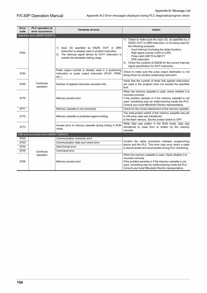
Appendix B: Message List
Appendix B-2 Error messages displayed during PLC diagnostic/program checkFX-30P Operation Manual
Operation error [M8067(D8067)]
6763
Continuesoperation
1) Input (X) specified by DSZR, DVIT or ZRNinstruction is already used in another instruction.
2) The interrupt signal device for DVIT instruction isoutside the allowable setting range.
1) Check to make sure the input (X), as specified by aDSZR, DVIT or ZRN instruction, is not being used forthe following purposes:
- Input interrupt (including the delay function)- High speed counter C235 to C255- Pulse catch M8170 to M8177- SPD instruction
2) Check the contents of D8336 for the correct interruptsignal specification for DVIT instruction.
6764Pulse output number is already used in a positioninginstruction or pulse output instruction (PLSY, PWM,etc.).
Check to make sure the pulse output destination is notbeing driven by another positioning instruction.
6765 Number of applied instruction exceeds limit.Verify that the number of times that applied instructionsare used in the program does not exceed the specifiedlimit.
6770 Memory access error
When the memory cassette is used, check whether it ismounted correctly.If the problem persists or if the memory cassette is notused, something may be malfunctioning inside the PLC.Consult your local Mitsubishi Electric representative.
6771 Memory cassette is not connected. Check for the correct attachment of the memory cassette.
6772 Memory cassette is protected against writing.The write-protect switch of the memory cassette was setto ON when data was transferredto the flash memory. Set the protect switch to OFF.
6773Access error to memory cassette during writing in RUNmode
While data was written in the RUN mode, data wastransferred to (read from or written to) the memorycassette.
USB communication error [M8487 (D8487)]
8702
Continues operation
Communication character errorConfirm the cable connection between programmingdevice and the PLC. This error may occur when a cableis disconnected and reconnected during PLC monitoring.
8703 Communication data sum check error
8704 Data format error
8705 Command error
8706 Memory access error
When the memory cassette is used, check whether it ismounted correctly.If the problem persists or if the memory cassette is notused, something may be malfunctioning inside the PLC.Consult your local Mitsubishi Electric representative.
Error code
PLC operation at error occurrence
Contents of error Action
154

Appendix B: Message List
Appendix B-2 Error messages displayed during PLC diagnostic/program checkFX-30P Operation Manual
1
Introduction
2
Specifications,product configuration
3
Connections,
startup procedure
4
Outline of
programm
ing
5
Online m
ode
6
Offline m
ode
7
HP
P setting
8
Battery
A
AS
CII C
ode
B
Message List
*1. The unit number 0 to 7 of the special function unit/block error is put in .
*2. "" indicates the following values for each special adapter/special block where an error hasoccurred.If an error has occurred in 2 or more special adapters/special blocks, "" indicates the lowest unitnumber among the special adapters/special blocks in which an error has occurred.
Error code
PLC operation at error occurrence
Contents of error Action
Special block error [M8449 (D8449)]
020*1
Continues operation
General data sum error
Verify that extension cables are correctly connected.
021*1 General data message error
022*1 System access error
025*1 Access sum error in other station via CC-Link
026*1 Message error in other station via CC-Link
030*1 Memory access error
When the memory cassette is used, check whether it ismounted correctly.If the problem persists or if the memory cassette is notused, something may be malfunctioning inside the PLC.Consult your local Mitsubishi Electric representative.
080*1 FROM/TO error
This error occurs in the execution of operation.• Review the program and check the contents of the
operands used in the applied instructions.• Verify that specified buffer memories exist in the
counterpart equipment.• Verify that extension cables are correctly connected.
090*1 Peripheral equipment access error
• Check the cable connection between theprogramming panel (PP) / programming device andthe PLC.
• Verify that extension cables are correctly connected.
Special parameter error [M8489 (D8489)]
01*2
Continues operation
Special parameter setting time-out errorTurn OFF the power, and check the power supply and connection of special adapters/special blocks.
02*2 Special parameter setting error
Special parameters are set improperly.• Confirm troubleshooting for special adapters/special
blocks, and set special parameters correctly.• Set special parameters correctly, turn OFF the power,
and then turn ON the power.
03*2 Special parameter transfer target unconnected error
Special parameters are set, but special adapters/special blocks are not connected.Check whether special adapters/special blocks are connected.
04*2 Special parameter unsupported functionCheck that special parameters with unsupported settings are not set for connected special adapters/special blocks.
Value of (decimal) Special adapter/special block where an error has occurred
00 Unit number 0 (Special block)
10 Unit number 1 (Special block)
20 Unit number 2 (Special block)
30 Unit number 3 (Special block)
40 Unit number 4 (Special block)
50 Unit number 5 (Special block)
60 Unit number 6 (Special block)
70 Unit number 7 (Special block)
81 Communication channel 1 (Special adapter)
82 Communication channel 2 (Special adapter)
155
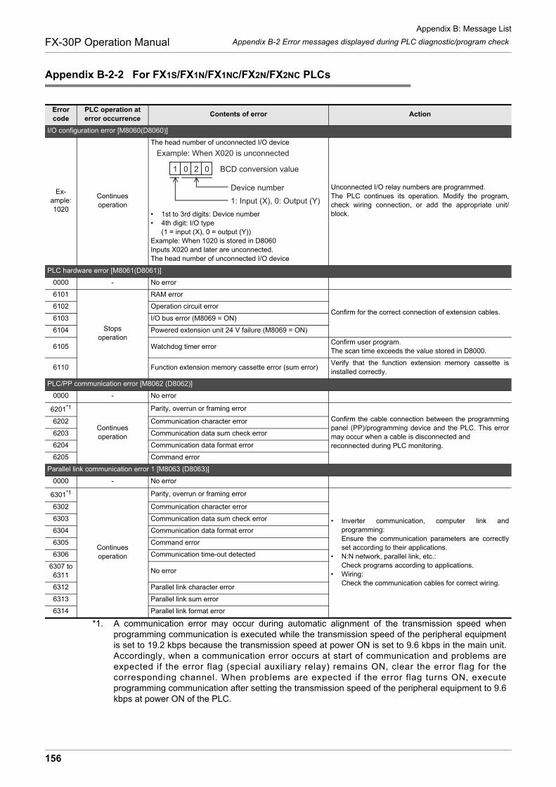
Appendix B: Message List
Appendix B-2 Error messages displayed during PLC diagnostic/program checkFX-30P Operation Manual
Appendix B-2-2 For FX1S/FX1N/FX1NC/FX2N/FX2NC PLCs
Error code
PLC operation at error occurrence
Contents of error Action
I/O configuration error [M8060(D8060)]
Ex-ample: 1020
Continues operation
The head number of unconnected I/O device
• 1st to 3rd digits: Device number• 4th digit: I/O type
(1 = input (X), 0 = output (Y))Example: When 1020 is stored in D8060Inputs X020 and later are unconnected.The head number of unconnected I/O device
Unconnected I/O relay numbers are programmed.The PLC continues its operation. Modify the program,check wiring connection, or add the appropriate unit/block.
PLC hardware error [M8061(D8061)]
0000 - No error
6101
Stopsoperation
RAM error
Confirm for the correct connection of extension cables.6102 Operation circuit error
6103 I/O bus error (M8069 = ON)
6104 Powered extension unit 24 V failure (M8069 = ON)
6105 Watchdog timer errorConfirm user program.The scan time exceeds the value stored in D8000.
6110 Function extension memory cassette error (sum error)Verify that the function extension memory cassette isinstalled correctly.
PLC/PP communication error [M8062 (D8062)]
0000 - No error
6201*1
Continues operation
Parity, overrun or framing error
Confirm the cable connection between the programmingpanel (PP)/programming device and the PLC. This errormay occur when a cable is disconnected and reconnected during PLC monitoring.
6202 Communication character error
6203 Communication data sum check error
6204 Communication data format error
6205 Command error
Parallel link communication error 1 [M8063 (D8063)]
0000 - No error
6301*1
Continues operation
Parity, overrun or framing error
• Inverter communication, computer link andprogramming:Ensure the communication parameters are correctlyset according to their applications.
• N:N network, parallel link, etc.:Check programs according to applications.
• Wiring:Check the communication cables for correct wiring.
6302 Communication character error
6303 Communication data sum check error
6304 Communication data format error
6305 Command error
6306 Communication time-out detected
6307 to6311
No error
6312 Parallel link character error
6313 Parallel link sum error
6314 Parallel link format error
*1. A communication error may occur during automatic alignment of the transmission speed whenprogramming communication is executed while the transmission speed of the peripheral equipmentis set to 19.2 kbps because the transmission speed at power ON is set to 9.6 kbps in the main unit.Accordingly, when a communication error occurs at start of communication and problems areexpected if the error flag (special auxiliary relay) remains ON, clear the error flag for thecorresponding channel. When problems are expected if the error flag turns ON, executeprogramming communication after setting the transmission speed of the peripheral equipment to 9.6kbps at power ON of the PLC.
1 0 2 0
1: Input (X), 0: Output (Y)
Device number
Example: When X020 is unconnected
BCD conversion value
156

Appendix B: Message List
Appendix B-2 Error messages displayed during PLC diagnostic/program checkFX-30P Operation Manual
1
Introduction
2
Specifications,product configuration
3
Connections,
startup procedure
4
Outline of
programm
ing
5
Online m
ode
6
Offline m
ode
7
HP
P setting
8
Battery
A
AS
CII C
ode
B
Message List
Parameter error [M8064(D8064)]
0000 - No error
6401
Stopsoperation
Program sum check error
STOP the PLC, and correctly set the parameters.
6402 Memory capacity setting error
6403 Latched device area setting error
6404 Comment area setting error
6405 File register area setting error
6409 Other setting error
Syntax error [M8065(D8065)]
0000 - No error
6501
Stopsoperation
Incorrect combination of instruction, device symbol anddevice number
During programming, each instruction is checked. If asyntax error is detected, modify the instruction correctly.
6502 No OUT T or OUT C before setting value
6503• No setting value after OUT T or OUT C• Insufficient number of operands for an applied
instruction
6504• Same label number is used more than once.• Same interrupt input or high speed counter input is
used more than once.
6505 Device number is out of allowable range.
6506 Invalid instruction
6507 Invalid label number [P]
6508 Invalid interrupt input [I]
6509 Other error
6510 MC nesting number error
6511Same interrupt input or high speed counter input is usedmore than once.
6512EXTR is described while the extension memory cassetteis not mounted.
Circuit error [M8066(D8066)]
0000 - No error
6601
Stopsoperation
LD, LDI is continuously used 9 times or more.
This error occurs when a combination of instructions isincorrect in the entire circuit block or when therelationship between a pair of instructions is incorrect.Modify the instructions in the program mode so that theirmutual relationship becomes correct.
6602
• No LD/LDI instruction.The use of LD/LDI or ANB/ORB instruction isincorrect.
• The following instructions are not connected to theactive bus line: STL, RET, MCR, (P)ointer, (I)nterrupt,EI,DI, SRET, IRET, FOR, NEXT, FEND and END.
• When MPP is missing
6603 MPS is used continuously more than 12 times
6604 The use of MPS, MRD, MPP instruction is incorrect.
6605
• The STL instruction is continuously used 9 times ormore.
• MC, MCR instruction, (I)nterrupt pointer or SRETinstruction is used within an STL program area.
• RET has not been used in the program or is notconnected to an STL instruction.
Error code
PLC operation at error occurrence
Contents of error Action
157

Appendix B: Message List
Appendix B-2 Error messages displayed during PLC diagnostic/program checkFX-30P Operation Manual
Circuit error [M8066(D8066)]
6606
Stopsoperation
• No (P)ointer, (I)nterrupt pointer.• No SRET/ IRET.• An (I)nterrupt pointer, SRET or IRET has been used
within the main program.• STL, RET, MC or MCR have been used within either
a subroutine or an interrupt routine.
This error occurs when a combination of instructions isincorrect in the entire circuit block or when therelationship between a pair of instructions is incorrect.Modify the instructions in the program mode so that theirmutual relationship becomes correct.
6607
• The use of FOR and NEXT is incorrect.• The following instructions have been used within a
FOR - NEXT loop : STL, RET, MC, MCR, IRET,SRET, FEND or END.
6608
• The use of MC/MCR is incorrect.• Missing MCR N0.• SRET, IRET instruction or an (I)nterrupt pointer has
been used within an MC/MCR instruction area.
6609 Other error
6610 LD, LDI is continuously used 9 times or more.
6611 More ANB/ORB instructions than LD/LDI instructions
6612 Less ANB/ORB instructions than LD/LDI instructions
6613 MPS is continuously used 12 times or more.
6614 No MPS instruction
6615 No MPP instruction
6616No coil between MPS, MRD and MPP, or incorrectcombination
6617Instruction below is not connected to bus line: STL, RET, MCR, P, I, DI, EI, FOR, NEXT, SRET, IRET,FEND or END
6618STL, MC or MCR can be used only in main program, butit is used elsewhere (e.g. in interrupt routine orsubroutine).
6619Invalid instruction is used in FOR-NEXT loop: STL, RET, MC, MCR, I (interrupt pointer) or IRET.
6620 FOR-NEXT instruction nesting level exceeded
6621 Numbers of FOR and NEXT instructions do not match.
6622 No NEXT instruction
6623 No MC instruction
6624 No MCR instruction
6625 STL instruction is continuously used 9 times or more.
6626Invalid instruction is programmed within STL-RET loop: MC, MCR, I (interrupt pointer), SRET or IRET.
6627 RET instruction not found
6628Invalid instruction is used in main program:I (interrupt pointer), SRET or IRET
6629 No P or I (interrupt pointer)
6630No SRET or IRET instructionSTL-RET / MC-MCR instructions programmed in thesubroutine.
6631 SRET programmed in invalid location
6632 FEND programmed in invalid location
Error code
PLC operation at error occurrence
Contents of error Action
158

Appendix B: Message List
Appendix B-2 Error messages displayed during PLC diagnostic/program checkFX-30P Operation Manual
1
Introduction
2
Specifications,product configuration
3
Connections,
startup procedure
4
Outline of
programm
ing
5
Online m
ode
6
Offline m
ode
7
HP
P setting
8
Battery
A
AS
CII C
ode
B
Message List
Operation error [M8067(D8067)]
0000 - No error
6701
Continues operation
• No jump destination (pointer) for CJ or CALL instruction
• (P)ointer is designated in a block that comes after theEND instruction
• An independent label is designated in a FOR-NEXTloop or a subroutine
This error occurs in the execution of operation. Reviewthe program, or check the contents of the operands usedin the applied instructions.Even if the syntax or circuit design is correct, an operationerror may still occur.For example:"T200Z" itself is not an error. But if Z had a value of 100,the timer T300 would be attempted to be accessed. Thiswould cause an operation error since there is no T600device available.
6702 CALL instruction nesting level is 6 or more
6703 Interrupt nesting level is 3 or more
6704 FOR-NEXT instruction nesting level is 6 or more.
6705 Operand of applied instruction is inapplicable device.
6706Device number range or data value for operand ofapplied instruction exceeds limit.
6707File register is accessed without parameter setting of fileregister.
6708FROM/TO instruction error(It becomes applicable "RD3A and the WR3Ainstruction".)
This error occurs in the execution of operation.• Review the program, or check the contents of the
operands used in the applied instructions.• Verify that the specified buffer memories exist in the
equipment.• Verify that the extension cables are correctly
connected.
6709Other error, i.e. missing IRE/ SRET, unauthorized FOR -NEXT relationship
This error occurs in the execution of operation. Reviewthe program, or check the contents of the operands usedin the applied instructions.Even if the syntax or circuit design is correct, an operationerror may still occur.For example:"T200Z" itself is not an error. But if Z had a value of 100,the timer T300 would be attempted to be accessed. Thiswould cause an operation error since there is no T600device available.
6730 Incorrect sampling time (TS) (TS 0)
<PID instruction is stopped.>This error occurs in the parameter setting value oroperation data executing PID instruction.Check the contents of the parameters.
6732Incompatible input filter constant ( )( < 0 or 100 )
6733 Incompatible proportional gain (KP) (KP < 0)
6734 Incompatible integral time (TI) (TI < 0)
6735Incompatible derivative gain (KD)(KD < 0 or 201 KD)
6736 Incompatible derivative time (TD) (TD < 0)
6740 Sampling time (TS) Scan time
<Operation data is made into a maximum value and it iscontinuation of operation>This error occurs in the parameter setting value oroperation data executing PID instruction.Check the contents of the parameters.
6742Variation of measured value exceeds limit.
( PV < -32768 or +32767 < PV)
6743Deviation exceeds limit.(EV < -32768 or +32767 < EV)
6744Integral result exceeds limit.(Outside range from -32768 to +32767)
6745Derivative value exceeds limit due to derivative gain(KD).
6746Derivative result exceeds limit.(Outside range from -32768 to +32767)
6747PID operation result exceeds limit.(Outside range from -32768 to +32767)
Error code
PLC operation at error occurrence
Contents of error Action
159

Appendix B: Message List
Appendix B-2 Error messages displayed during PLC diagnostic/program checkFX-30P Operation Manual
Operation error [M8067(D8067)]
6750Continues operation
<Step response method>Improper auto tuning result
<Auto tuning is finished. PID operation is started.>• The deviation at start of auto tuning is 150 or less. • The deviation at end of auto tuning is 1/3 or more of
the deviation at start of auto tuning. Check the measured value and target value, and thenexecute auto tuning again.
6751 -<Step response method>Auto tuning operation direction mismatch
<Auto tuning is forcibly finished. PID operation is notstarted.>The operation direction estimated from the measuredvalue at the start of auto tuning was different from theactual operation direction of the output during auto tuning.Correct the relationship among the target value, outputvalue for auto tuning, and the measured value, and thenexecute auto tuning again.
6752 -<Step response method>Improper auto tuning operation
<Auto tuning is finished. PID operation is not started.>Because the set value was fluctuated during auto tuning,auto tuning was not executed correctly.Set the sampling time to a value larger than the outputchange cycle, or set a larger value for the input filterconstant.After changing the setting, execute auto tuning again.
6760 - ABS data read from servo sum check errorCheck servo wiring and parameter setting. Also check theABS instruction.
Error code
PLC operation at error occurrence
Contents of error Action
160
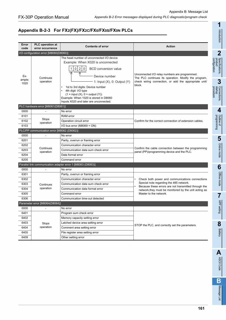
Appendix B: Message List
Appendix B-2 Error messages displayed during PLC diagnostic/program checkFX-30P Operation Manual
1
Introduction
2
Specifications,product configuration
3
Connections,
startup procedure
4
Outline of
programm
ing
5
Online m
ode
6
Offline m
ode
7
HP
P setting
8
Battery
A
AS
CII C
ode
B
Message List
Appendix B-2-3 For FX2(FX)/FX2C/FX0/FX0S/FX0N PLCs
Error code
PLC operation at error occurrence
Contents of error Action
I/O configuration error [M8060(D8060)]
Ex-ample: 1020
Continues operation
The head number of unconnected I/O device
• 1st to 3rd digits: Device number• 4th digit: I/O type
(1 = input (X), 0 = output (Y))Example: When 1020 is stored in D8060Inputs X020 and later are unconnected.
Unconnected I/O relay numbers are programmed.The PLC continues its operation. Modify the program,check wiring connection, or add the appropriate unit/block.
PLC hardware error [M8061(D8061)]
0000 - No error
6101Stops
operation
RAM error
Confirm for the correct connection of extension cables.6102 Operation circuit error
6103 I/O bus error (M8069 = ON)
PLC/PP communication error [M8062 (D8062)]
0000 - No error
6201
Continues operation
Parity, overrun or framing error
Confirm the cable connection between the programmingpanel (PP)/programming device and the PLC.
6202 Communication character error
6203 Communication data sum check error
6204 Data format error
6205 Command error
Parallel link communication adapter error 1 [M8063 (D8063)]
0000 - No error
6301
Continues operation
Parity, overrun or framing error
• Check both power and communications connectionsSpecial note regarding the 485 network.
• Because these errors are not transmitted through thenetwork,they must be monitored by the unit acting asMaster to the network.
6302 Communication character error
6303 Communication data sum check error
6304 Communication data format error
6305 Command error
6306 Communication time-out detected
Parameter error [M8064(D8064)]
0000 - No error
6401
Stopsoperation
Program sum check error
STOP the PLC, and correctly set the parameters.
6402 Memory capacity setting error
6403 Latched device area setting error
6404 Comment area setting error
6405 File register area setting error
6409 Other setting error
1 0 2 0
1: Input (X), 0: Output (Y)
Device number
Example: When X020 is unconnected
BCD conversion value
161
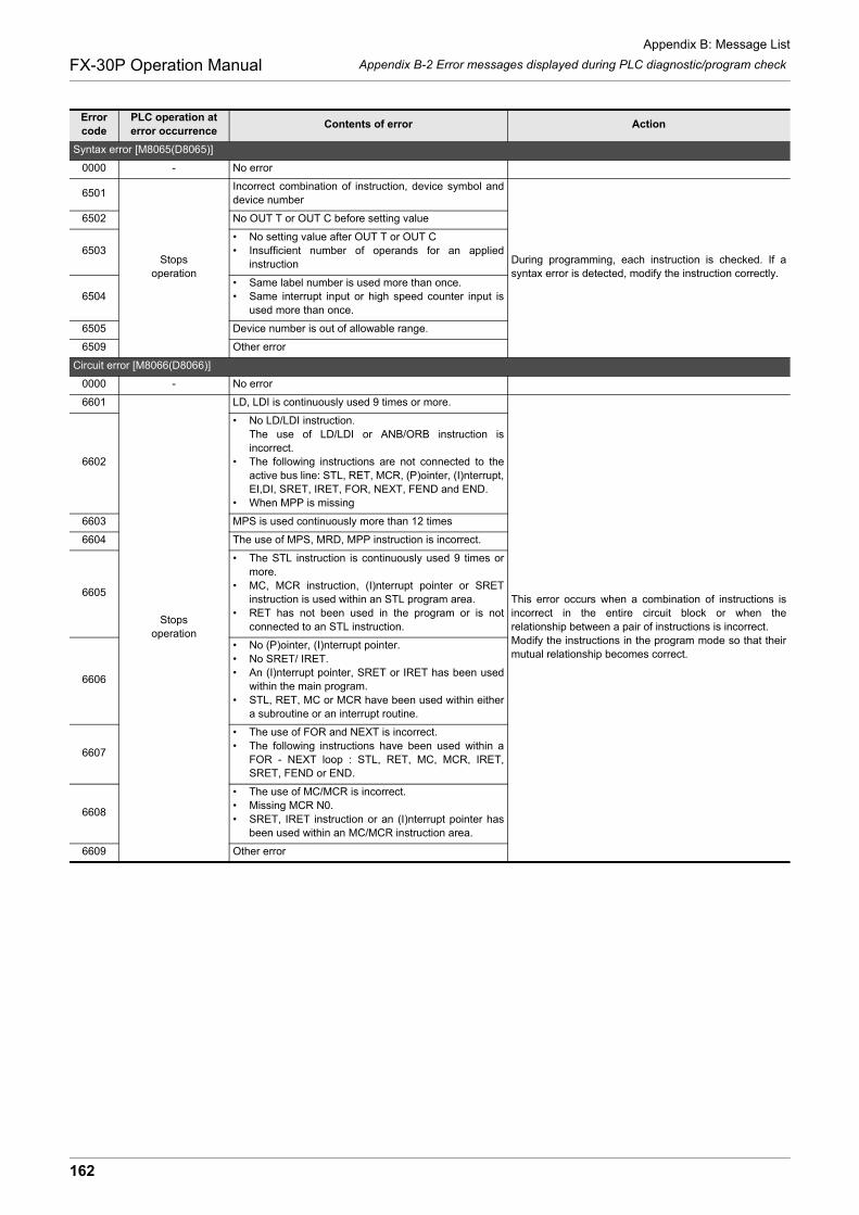
Appendix B: Message List
Appendix B-2 Error messages displayed during PLC diagnostic/program checkFX-30P Operation Manual
Syntax error [M8065(D8065)]
0000 - No error
6501
Stopsoperation
Incorrect combination of instruction, device symbol anddevice number
During programming, each instruction is checked. If asyntax error is detected, modify the instruction correctly.
6502 No OUT T or OUT C before setting value
6503• No setting value after OUT T or OUT C• Insufficient number of operands for an applied
instruction
6504• Same label number is used more than once.• Same interrupt input or high speed counter input is
used more than once.
6505 Device number is out of allowable range.
6509 Other error
Circuit error [M8066(D8066)]
0000 - No error
6601
Stopsoperation
LD, LDI is continuously used 9 times or more.
This error occurs when a combination of instructions isincorrect in the entire circuit block or when therelationship between a pair of instructions is incorrect.Modify the instructions in the program mode so that theirmutual relationship becomes correct.
6602
• No LD/LDI instruction.The use of LD/LDI or ANB/ORB instruction isincorrect.
• The following instructions are not connected to theactive bus line: STL, RET, MCR, (P)ointer, (I)nterrupt,EI,DI, SRET, IRET, FOR, NEXT, FEND and END.
• When MPP is missing
6603 MPS is used continuously more than 12 times
6604 The use of MPS, MRD, MPP instruction is incorrect.
6605
• The STL instruction is continuously used 9 times ormore.
• MC, MCR instruction, (I)nterrupt pointer or SRETinstruction is used within an STL program area.
• RET has not been used in the program or is notconnected to an STL instruction.
6606
• No (P)ointer, (I)nterrupt pointer.• No SRET/ IRET.• An (I)nterrupt pointer, SRET or IRET has been used
within the main program.• STL, RET, MC or MCR have been used within either
a subroutine or an interrupt routine.
6607
• The use of FOR and NEXT is incorrect.• The following instructions have been used within a
FOR - NEXT loop : STL, RET, MC, MCR, IRET,SRET, FEND or END.
6608
• The use of MC/MCR is incorrect.• Missing MCR N0.• SRET, IRET instruction or an (I)nterrupt pointer has
been used within an MC/MCR instruction area.
6609 Other error
Error code
PLC operation at error occurrence
Contents of error Action
162
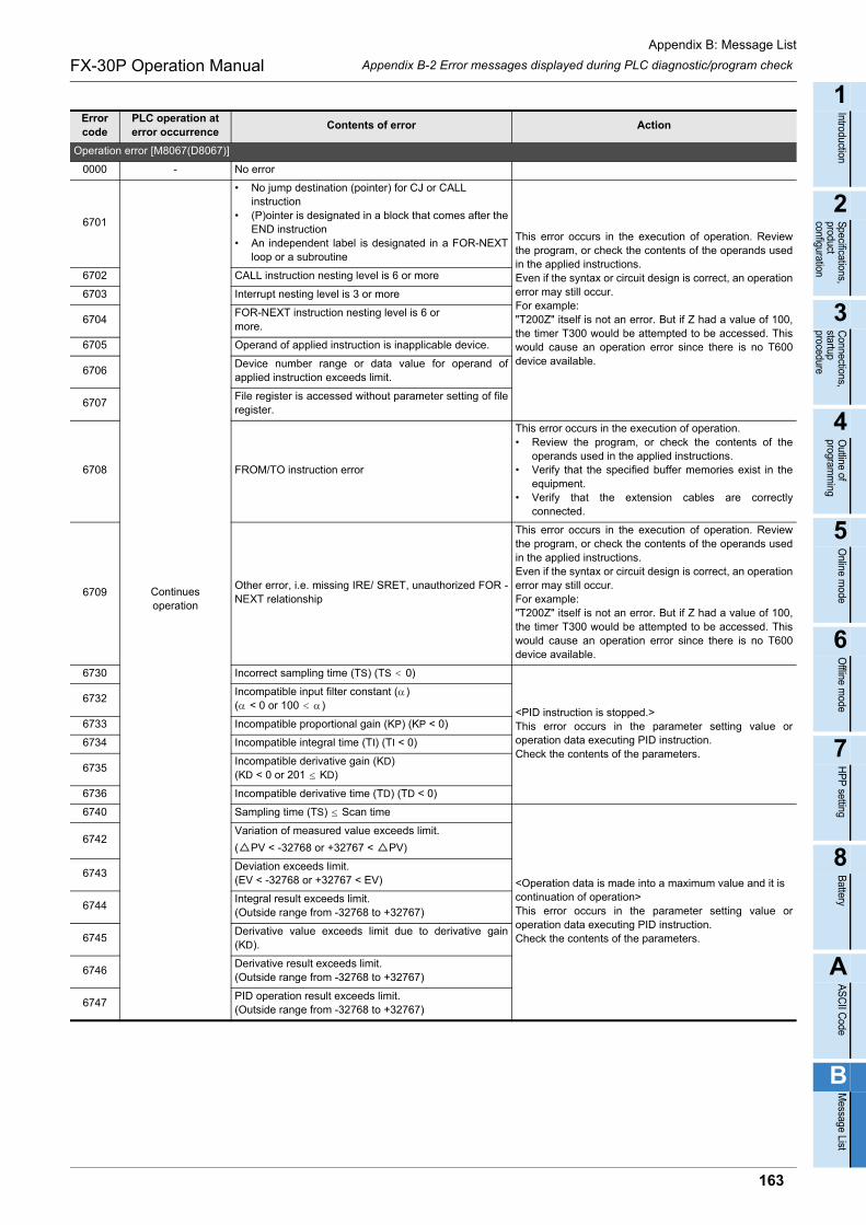
Appendix B: Message List
Appendix B-2 Error messages displayed during PLC diagnostic/program checkFX-30P Operation Manual
1
Introduction
2
Specifications,product configuration
3
Connections,
startup procedure
4
Outline of
programm
ing
5
Online m
ode
6
Offline m
ode
7
HP
P setting
8
Battery
A
AS
CII C
ode
B
Message List
Operation error [M8067(D8067)]
0000 - No error
6701
Continues operation
• No jump destination (pointer) for CJ or CALL instruction
• (P)ointer is designated in a block that comes after theEND instruction
• An independent label is designated in a FOR-NEXTloop or a subroutine
This error occurs in the execution of operation. Reviewthe program, or check the contents of the operands usedin the applied instructions.Even if the syntax or circuit design is correct, an operationerror may still occur.For example:"T200Z" itself is not an error. But if Z had a value of 100,the timer T300 would be attempted to be accessed. Thiswould cause an operation error since there is no T600device available.
6702 CALL instruction nesting level is 6 or more
6703 Interrupt nesting level is 3 or more
6704FOR-NEXT instruction nesting level is 6 or more.
6705 Operand of applied instruction is inapplicable device.
6706Device number range or data value for operand ofapplied instruction exceeds limit.
6707File register is accessed without parameter setting of fileregister.
6708 FROM/TO instruction error
This error occurs in the execution of operation.• Review the program, or check the contents of the
operands used in the applied instructions.• Verify that the specified buffer memories exist in the
equipment.• Verify that the extension cables are correctly
connected.
6709Other error, i.e. missing IRE/ SRET, unauthorized FOR -NEXT relationship
This error occurs in the execution of operation. Reviewthe program, or check the contents of the operands usedin the applied instructions.Even if the syntax or circuit design is correct, an operationerror may still occur.For example:"T200Z" itself is not an error. But if Z had a value of 100,the timer T300 would be attempted to be accessed. Thiswould cause an operation error since there is no T600device available.
6730 Incorrect sampling time (TS) (TS 0)
<PID instruction is stopped.>This error occurs in the parameter setting value oroperation data executing PID instruction.Check the contents of the parameters.
6732Incompatible input filter constant ( )( < 0 or 100 )
6733 Incompatible proportional gain (KP) (KP < 0)
6734 Incompatible integral time (TI) (TI < 0)
6735Incompatible derivative gain (KD)(KD < 0 or 201 KD)
6736 Incompatible derivative time (TD) (TD < 0)
6740 Sampling time (TS) Scan time
<Operation data is made into a maximum value and it iscontinuation of operation>This error occurs in the parameter setting value oroperation data executing PID instruction.Check the contents of the parameters.
6742Variation of measured value exceeds limit.
( PV < -32768 or +32767 < PV)
6743Deviation exceeds limit.(EV < -32768 or +32767 < EV)
6744Integral result exceeds limit.(Outside range from -32768 to +32767)
6745Derivative value exceeds limit due to derivative gain(KD).
6746Derivative result exceeds limit.(Outside range from -32768 to +32767)
6747PID operation result exceeds limit.(Outside range from -32768 to +32767)
Error code
PLC operation at error occurrence
Contents of error Action
163

Appendix C: Major Key Operation List
FX-30P Operation Manual
Appendix C: Major Key Operation List
Key operation example Description
HPP reset
• [RST]+[GO] (Key is pressed at thesame time)
Resets the HPP (and displays the screen which is usually displayed during startup).
Read
• [ ] / [ ] Moves the cursor by 1 line at a time from the currently displayed position.
• [GO] Scrolls the display by one screen.
• [STEP] [1] [0] [GO]Searches and displays the program by step No.Press the [GO] key again to scroll the program by one screen.
• [LD] [X] [1] [0] [GO]Searches and displays the program by instruction anddevice.
Press the [GO] key again to search the remaining portion of the program.
• [SP] [X] [1] [1] [GO] Searches and displays the program by device.
• [FNC] [1] [2]Searches and displays an (16-bit type) application instruction. Pulse execution (P)
does not have to beinput.• [FNC] [D] [1] [2]
Searches and displays an (32-bit type) application instruction.
• [P] [0] [GO] Searches and displays the program by label and pointer.
Write
Contactinstructions
• [LD] [X] [1] [0] [GO]• [LDI] [X] [1] [1] [GO]
For the LD, LDI, AND, ANI and ORI instructions, consecutively input a device aftera contact instruction.
• [LD] [P/I] [X] [1] [2] [GO]• [LD] [F] [X] [1] [3] [GO]
For the LDP, LDF, ANP, ANF, ORP and ORF instructions, press the [P/I] or [F] keyafter a contact instruction, then consecutively input a device.
• [NOP] [P/I] [X] [1] [4][GO]
For the INV instruction, press the [NOP] and [P/I] keys instead, then consecutivelyinput a device after that.
Data comparisioninstructions
Input it as an application instruction.
Blockinstructions/instructionsfor storageduringoperation
• [ANB] [GO]• [ORB] [GO]• [MPS] [GO]• [MRD] [GO]• [MPP] [GO]
For block instructions (ANB and ORB) and instructions which store theintermediate result of the operation (MPS, MRD and MPP), input only aninstruction.
Driveinstructions
• [OUT] [Y] [2] [GO]• [OUT] [T] [0] [SP] [K] [1]
[0] [0] [GO]
For the OUT instruction for an output (Y), auxiliary relay (M) or state (S), input adevice after the instruction.For the OUT instruction for a timer (T) or counter (C), input a device and set valueafter the instruction.
• [SET][M][1][0][0]• [RST][C][1][0]
For the SET and RST instructions, input a device after an instruction.
MCinstructions
• [MC] [0] [SP] [M] [1] [0][0] [GO]
• [MCR] [0] [GO]
For the MC instruction, input the nesting level and device after it. For the MCR instruction, input the nesting level after it.
Applicationinstructions(16-bit type)
• [FNC] [1] [2] [SP] [K][1] [0] [SP] [D] [0] [GO]
• [FNC] [HELP] [1] [2][SP] [K] [1] [0] [SP] [D][0] [GO]
For an application instruction, enter via the FNC No., then enter an operand after it.If the FNC No. is unknown, press the [FNC] key first, then press the [HELP] key toselect an instruction.When entering an operand, press the [SP] key to delimit the instruction, the sourceand the destination.When entering a constant, press the [K] key once for decimal, or twice forhexadecimal ("H" is displayed.).
Applicationinstructions(32-bit type)
• [FNC] [1] [2] [D] [SP][K] [1] [0] [SP] [D] [0] [GO]
• [FNC] [HELP] [1] [2][D] [SP] [K] [1] [0] [SP] [D] [0] [GO]
When inputting a 32-bit instruction, press the [D] key after entering the FNC No.If the FNC No. is unknown, press the [FNC] key first, press the [HELP] key toselect an instruction, then press the [D] key. In either case, input an operand afterpressing the [D] key. When inputting an operand, press the [SP] key to delimit the instruction, the sourceand the destination. When inputting a constant, press the [K] key once for decimal,or twice for hexadecimal ("H" is displayed.).
164
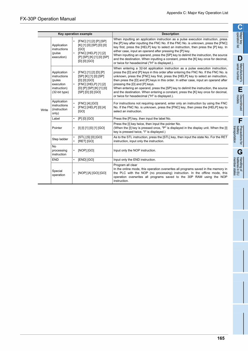
Appendix C: Major Key Operation List
FX-30P Operation Manual
C
Major key
operation list
D
Manufacturer's
serial number
E
Discontinued
models
F
Precautions for
batterytransportation
G
Handling of
batteries in EU
mem
ber states
Write
Applicationinstructions(pulseexecution)
• [FNC] [1] [2] [P] [SP][K] [1] [0] [SP] [D] [0][GO]
• [FNC] [HELP] [1] [2][P] [SP] [K] [1] [0] [SP] [D] [0] [GO]
When inputting an application instruction as a pulse execution instruction, pressthe [P] key after inputting the FNC No. If the FNC No. is unknown, press the [FNC]key first, press the [HELP] key to select an instruction, then press the [P] key. Ineither case, input an operand after pressing the [P] key.When inputting an operand, press the [SP] key to delimit the instruction, the sourceand the destination. When inputting a constant, press the [K] key once for decimal,or twice for hexadecimal ("H" is displayed.).
Applicationinstructions(pules executioninstruction)(32-bit type)
• [FNC] [1] [2] [D] [P][SP] [K] [1] [0] [SP] [D] [0] [GO]
• [FNC] [HELP] [1] [2][D] [P] [SP] [K] [1] [0][SP] [D] [0] [GO]
When entering a 32-bit application instruction as a pulse execution instruction,press the [D] and [P] keys in this order after entering the FNC No. If the FNC No. isunknown, press the [FNC] key first, press the [HELP] key to select an instruction,then press the [D] and [P] keys in this order. In either case, input an operand afterpressing the [D] and [P] keys. When entering an operand, press the [SP] key to delimit the instruction, the sourceand the destination. When entering a constant, press the [K] key once for decimal,or twice for hexadecimal ("H" is displayed.).
Applicationinstructions(instructiononly)
• [FNC] [4] [GO]• [FNC] [HELP] [0] [4]
[GO]
For instructions not requiring operand, enter only an instruction by using the FNCNo. If the FNC No. is unknown, press the [FNC] key, then press the [HELP] key toselect an instruction.
Label • [P] [0] [GO] Press the [P] key, then input the label No.
Pointer • [I] [I] [1] [0] [1] [GO]Press the [I] key twice, then input the pointer No. (When the [I] key is pressed once, "P" is displayed in the display unit. When the [I]key is pressed twice, "I" is displayed.)
Step ladder• [STL] [S] [0] [GO]• [RET] [GO]
As to the STL instruction, press the [STL] key, then input the state No. For the RETinstruction, input only the instruction.
Noprocessing instruction
• [NOP] [GO] Input only the NOP instruction.
END • [END] [GO] Input only the END instruction.
Specialoperation
• [NOP] [A] [GO] [GO]
Program all clearIn the online mode, this operation overwrites all programs saved in the memory inthe PLC with the NOP (no processing) instruction. In the offline mode, thisoperation overwrites all programs saved to the 30P RAM using the NOPinstruction.
Key operation example Description
165

Appendix D-1 Version check methodFX-30P Operation ManualAppendix D: Manufacturer's serial number/Version Information
Appendix D: Manufacturer's serial number/Version Information
Appendix D-1 Version check method
The manufacturing date of the product is identified by the number indicated by "S/N" written an the back label.
Example nameplate (manufacturer's serial number: 1010001)
Year (Example: 2009): Last digit of year Year (Example: 2010): Last two digit of year
01 1 0 0 0
Control number
<Product from January, 2010><Product during December, 2009 or earlier>
1
Month (Example: Jan.):1 to 9 = January to September,X = October, Y = November, Z = December
9 Z 0 0 0
Control number
1
Month (Example: Dec.):1 to 9 = January to September,X = October, Y = November, Z = December
*Actual product nameplate differs from the example shown above.
166
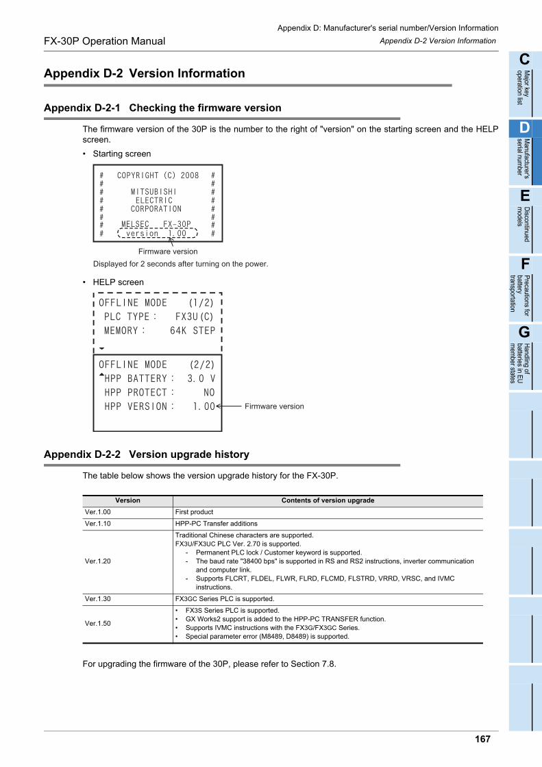
Appendix D-2 Version InformationFX-30P Operation Manual
C
Major key
operation list
D
Manufacturer's
serial number
E
Discontinued
models
F
Precautions for
batterytransportation
G
Handling of
batteries in EU
mem
ber statesAppendix D: Manufacturer's serial number/Version Information
Appendix D-2 Version Information
Appendix D-2-1 Checking the firmware version
The firmware version of the 30P is the number to the right of "version" on the starting screen and the HELPscreen.
• Starting screen
• HELP screen
Appendix D-2-2 Version upgrade history
The table below shows the version upgrade history for the FX-30P.
For upgrading the firmware of the 30P, please refer to Section 7.8.
Version Contents of version upgrade
Ver.1.00 First product
Ver.1.10 HPP-PC Transfer additions
Ver.1.20
Traditional Chinese characters are supported.FX3U/FX3UC PLC Ver. 2.70 is supported.
- Permanent PLC lock / Customer keyword is supported.- The baud rate "38400 bps" is supported in RS and RS2 instructions, inverter communication
and computer link.- Supports FLCRT, FLDEL, FLWR, FLRD, FLCMD, FLSTRD, VRRD, VRSC, and IVMC
instructions.
Ver.1.30 FX3GC Series PLC is supported.
Ver.1.50
• FX3S Series PLC is supported.• GX Works2 support is added to the HPP-PC TRANSFER function.• Supports IVMC instructions with the FX3G/FX3GC Series.• Special parameter error (M8489, D8489) is supported.
Displayed for 2 seconds after turning on the power.
Firmware version
Firmware version
167

Appendix D-2 Version InformationFX-30P Operation ManualAppendix D: Manufacturer's serial number/Version Information
MEMO
168
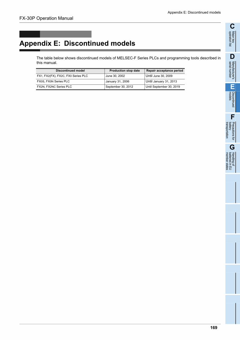
Appendix E: Discontinued models
FX-30P Operation Manual
C
Major key
operation list
D
Manufacturer's
serial number
E
Discontinued
models
F
Precautions for
batterytransportation
G
Handling of
batteries in EU
mem
ber states
Appendix E: Discontinued models
The table below shows discontinued models of MELSEC-F Series PLCs and programming tools described inthis manual.
Discontinued model Production stop date Repair acceptance period
FX1, FX2(FX), FX2C, FX0 Series PLC June 30, 2002 Until June 30, 2009
FX0S, FX0N Series PLC January 31, 2006 Until January 31, 2013
FX2N, FX2NC Series PLC September 30, 2012 Until September 30, 2019
169

Appendix E: Discontinued models
FX-30P Operation Manual
MEMO
170
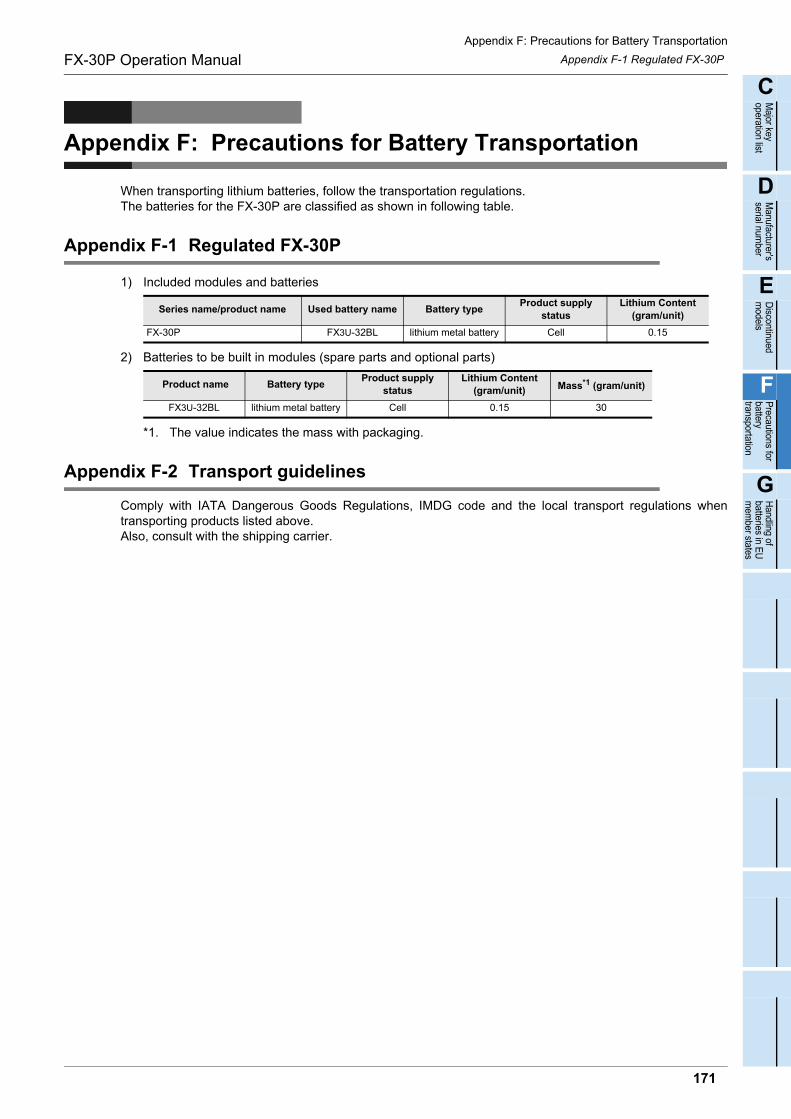
Appendix F: Precautions for Battery Transportation
Appendix F-1 Regulated FX-30PFX-30P Operation Manual
C
Major key
operation list
D
Manufacturer's
serial number
E
Discontinued
models
F
Precautions for
batterytransportation
G
Handling of
batteries in EU
mem
ber states
Appendix F: Precautions for Battery Transportation
When transporting lithium batteries, follow the transportation regulations.The batteries for the FX-30P are classified as shown in following table.
Appendix F-1 Regulated FX-30P
1) Included modules and batteries
2) Batteries to be built in modules (spare parts and optional parts)
*1. The value indicates the mass with packaging.
Appendix F-2 Transport guidelines
Comply with IATA Dangerous Goods Regulations, IMDG code and the local transport regulations whentransporting products listed above.Also, consult with the shipping carrier.
Series name/product name Used battery name Battery typeProduct supply
statusLithium Content
(gram/unit)
FX-30P FX3U-32BL lithium metal battery Cell 0.15
Product name Battery typeProduct supply
statusLithium Content
(gram/unit) Mass*1 (gram/unit)
FX3U-32BL lithium metal battery Cell 0.15 30
171

Appendix F: Precautions for Battery Transportation
Appendix F-2 Transport guidelinesFX-30P Operation Manual
MEMO
172
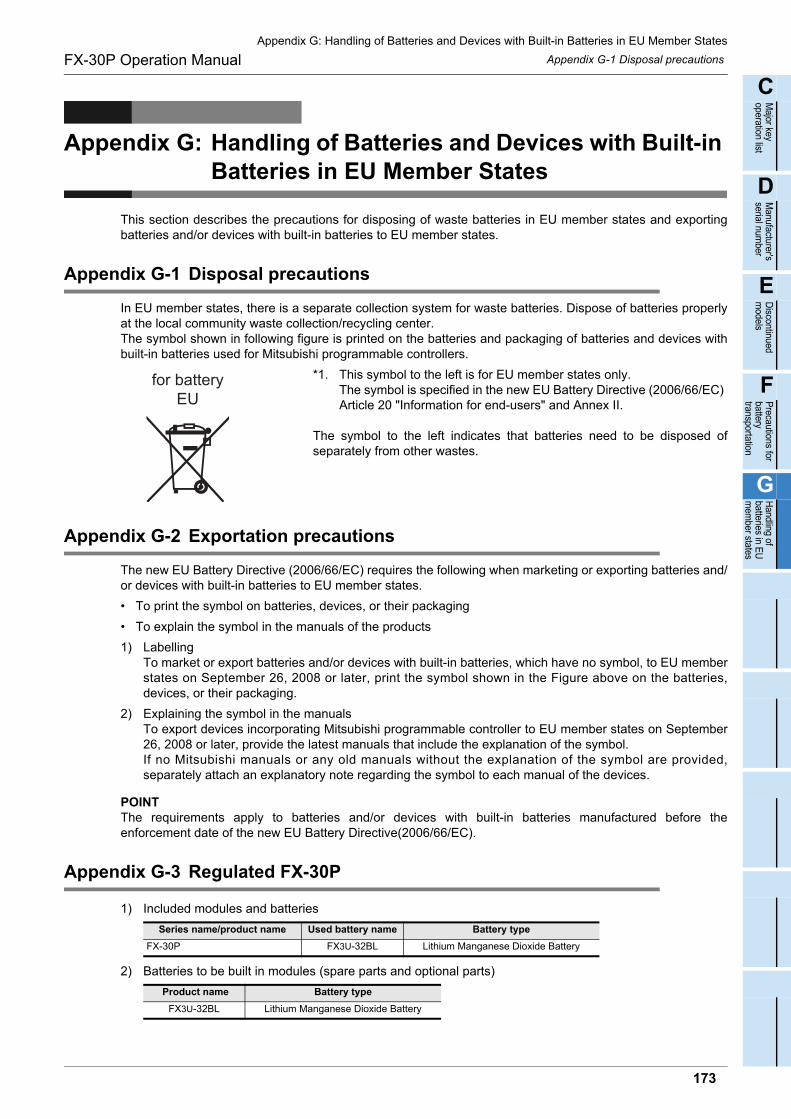
Appendix G-1 Disposal precautionsFX-30P Operation Manual
C
Major key
operation list
D
Manufacturer's
serial number
E
Discontinued
models
F
Precautions for
batterytransportation
G
Handling of
batteries in EU
mem
ber statesAppendix G: Handling of Batteries and Devices with Built-in Batteries in EU Member States
Appendix G: Handling of Batteries and Devices with Built-in Batteries in EU Member States
This section describes the precautions for disposing of waste batteries in EU member states and exportingbatteries and/or devices with built-in batteries to EU member states.
Appendix G-1 Disposal precautions
In EU member states, there is a separate collection system for waste batteries. Dispose of batteries properlyat the local community waste collection/recycling center. The symbol shown in following figure is printed on the batteries and packaging of batteries and devices withbuilt-in batteries used for Mitsubishi programmable controllers.
*1. This symbol to the left is for EU member states only.The symbol is specified in the new EU Battery Directive (2006/66/EC)Article 20 "Information for end-users" and Annex II.
The symbol to the left indicates that batteries need to be disposed ofseparately from other wastes.
Appendix G-2 Exportation precautions
The new EU Battery Directive (2006/66/EC) requires the following when marketing or exporting batteries and/or devices with built-in batteries to EU member states.
• To print the symbol on batteries, devices, or their packaging
• To explain the symbol in the manuals of the products
1) LabellingTo market or export batteries and/or devices with built-in batteries, which have no symbol, to EU memberstates on September 26, 2008 or later, print the symbol shown in the Figure above on the batteries,devices, or their packaging.
2) Explaining the symbol in the manualsTo export devices incorporating Mitsubishi programmable controller to EU member states on September26, 2008 or later, provide the latest manuals that include the explanation of the symbol.If no Mitsubishi manuals or any old manuals without the explanation of the symbol are provided,separately attach an explanatory note regarding the symbol to each manual of the devices.
POINTThe requirements apply to batteries and/or devices with built-in batteries manufactured before theenforcement date of the new EU Battery Directive(2006/66/EC).
Appendix G-3 Regulated FX-30P
1) Included modules and batteries
2) Batteries to be built in modules (spare parts and optional parts)
Series name/product name Used battery name Battery type
FX-30P FX3U-32BL Lithium Manganese Dioxide Battery
Product name Battery type
FX3U-32BL Lithium Manganese Dioxide Battery
for batteryEU
173

Appendix G-3 Regulated FX-30PFX-30P Operation ManualAppendix G: Handling of Batteries and Devices with Built-in Batteries in EU Member States
MEMO
174
FX-30P Operation Manual Warranty
Warranty
Please confirm the following product warranty details before u
sing this product.1. Gratis Warranty Term and Gratis Warranty Range
[Gratis Warranty Term]
If any faults or defects (hereinafter "Failure") found to be the responsibility of Mitsubishi occurs during use of the product within the gratis warranty term, the product shall be repaired at no cost via the sales representative or Mitsubishi Service Company. However, if repairs are required onsite at domestic or overseas location, expenses to send an engineer will be solely at the customer's discretion. Mitsubishi shall not be held responsible for any re-commissioning, maintenance, or testing on-site that involves replacement of the failed module.
Overseas, repairs shall be accepted by Mitsubishi's local overseas FA Center. Note that the repair conditions at each FA Center may differ. The gratis warranty term of the product shall be for one
year after the date of purchase or delivery to a designated place. Note that after manufacture and shipment from Mitsubishi, the maximum distribution period shall be six (6) months, and the longest gratis warranty term after manufacturing shall be eighteen (18) months. The gratis warranty term of repair parts shall not exceed the gratis warranty term before repairs.
[Gratis Warranty Range]
The range shall be limited to normal use within the usage state, usage methods and usage environment, etc., which follow the conditions and precautions, etc., given in the instruction manual, user's manual and caution labels on the product.
1)
Even within the gratis warranty term, repairs shall be charged for in the following cases.
2)
Failure occurring from inappropriate storage or handling, carelessness or negligence by the user. Failure caused by the user's hardware or software design.
a)
Failure caused by unapproved modifications, etc., to the product by the user.
b)
Mitsubishi shall accept onerous product repairs for seven (7) years after production of the product is discontinued.Discontinuation of production shall be notified with Mitsubishi Technical Bulletins, etc.
1)
Product supply (including repair parts) is not available after production is discontinued.
2)
In using the Mitsubishi MELSEC programmable logic controller, the usage conditions shall be that the application will not lead to a major accident even if any problem or fault should occur in the programmable logic controller device, and that backup and fail-safe functions are systematically provided outside of the device for any problem or fault.
1)
The Mitsubishi programmable logic controller has been designed and manufactured for applications in general industries, etc. Thus, applications in which the public could be affected such as in nuclear power plants and other power plants operated by respective power companies, and applications in which a special quality assurance system is required, such as for Railway companies or Public service purposes shall be excluded from the programmable logic controller applications. In addition, applications in which human life or property that could be greatly affected, such as in aircraft, medical applications, incineration and fuel devices, manned transportation, equipment for recreation and amusement, and safety devices, shall also be excluded from the programmable logic controller range of applications. However, in certain cases, some applications may be possible, providing the user consults their local Mitsubishi representative outlining the special requirements of the project, and providing that all parties concerned agree to the special circumstances, solely at the users discretion.
2)
When the Mitsubishi product is assembled into a user's device, Failure that could have been avoided if functions or structures, judged as necessary in the legal safety measures the user's device is subject to or as necessary by industry standards, had been provided.
c)
Failure that could have been avoided if consumable parts (battery, backlight, fuse, etc.) designated in the instruction manual had been correctly serviced or replaced.
d)
Relay failure or output contact failure caused by usage beyond the specified Life of contact (cycles).
e)
Failure caused by external irresistible forces such as fires or abnormal voltages, and failure caused by force majeure such as earthquakes, lightning, wind and water damage.
f)
Failure caused by reasons unpredictable by scientific technology standards at time of shipment from Mitsubishi.
g)
Any other failure found not to be the responsibility of Mitsubishi or that admitted not to be so by the user.
h)
2. Onerous repair term after discontinuation of production
4. Exclusion of loss in opportunity and secondary loss from warranty liability
3. Overseas service
The specifications given in the catalogs, manuals or technical documents are subject to change without prior notice.
5. Changes in product specifications
6. Product application
Regardless of the gratis warranty term, Mitsubishi shall not be liable for compensation of damages caused by any cause found not to be the responsibility of Mitsubishi, loss in opportunity, lost profits incurred to the user or third person by Failures of Mitsubishi products, special damages and secondary damages whether foreseeable or not, compensation for accidents, and compensation for damages to products other than Mitsubishi products, replacement by the user, maintenance of on-site equipment, start-up test run and other tasks.
175
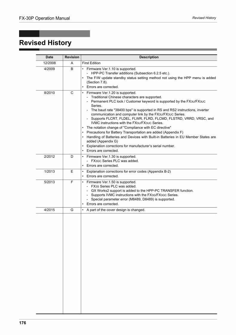
FX-30P Operation Manual Revised History
Revised History
Date Revision Description
12/2008 A First Edition
4/2009 B • Firmware Ver.1.10 is supported.- HPP-PC Transfer additions (Subsection 6.2.5 etc.).
• The F/W update standby status setting method not using the HPP menu is added(Section 7.8).
• Errors are corrected.
8/2010 C • Firmware Ver.1.20 is supported.- Traditional Chinese characters are supported.- Permanent PLC lock / Customer keyword is supported by the FX3U/FX3UC
Series.- The baud rate "38400 bps" is supported in RS and RS2 instructions, inverter
communication and computer link by the FX3U/FX3UC Series.- Supports FLCRT, FLDEL, FLWR, FLRD, FLCMD, FLSTRD, VRRD, VRSC, and
IVMC instructions with the FX3U/FX3UC Series.• The notation change of "Compliance with EC directive"• Precautions for Battery Transportation are added (Appendix F)• Handling of Batteries and Devices with Built-in Batteries in EU Member States are
added (Appendix G)• Explanation corrections for manufacturer’s serial number.• Errors are corrected.
2/2012 D • Firmware Ver.1.30 is supported.- FX3GC Series PLC was added.
• Errors are corrected.
1/2013 E • Explanation corrections for error codes (Appendix B-2)• Errors are corrected.
5/2013 F • Firmware Ver.1.50 is supported.- FX3S Series PLC was added.- GX Works2 support is added to the HPP-PC TRANSFER function.- Supports IVMC instructions with the FX3G/FX3GC Series.- Special parameter error (M8489, D8489) is supported.
• Errors are corrected.
4/2015 G • A part of the cover design is changed.
176

HEAD OFFICE: TOKYO BUILDING, 2-7-3 MARUNOUCHI, CHIYODA-KU, TOKYO 100-8310, JAPAN
JY997D34401G(MEE)
Effective April 2015Specifications are subject to change without notice.
FX-30P
OPERATION MANUAL
MODEL FX-30P-O-E
MODEL CODE 09R924