FWM Dynamics Under Dual-Pump Thermal Behavior in Silicon ...
10
FWM Dynamics Under Dual-Pump Thermal Behavior in Silicon Microring Resonator Volume 7, Number 1, February 2015 Heng Zhou Mingle Liao Kun Qiu Baojian Wu Yun Ling Feng Wen Linjie Zhou Jianping Chen DOI: 10.1109/JPHOT.2015.2388859 1943-0655 Ó 2015 IEEE
Transcript of FWM Dynamics Under Dual-Pump Thermal Behavior in Silicon ...

FWM Dynamics Under Dual-Pump ThermalBehavior in Silicon Microring ResonatorVolume 7, Number 1, February 2015
Heng ZhouMingle LiaoKun QiuBaojian WuYun LingFeng WenLinjie ZhouJianping Chen
DOI: 10.1109/JPHOT.2015.23888591943-0655 Ó 2015 IEEE

FWM Dynamics Under Dual-Pump ThermalBehavior in Silicon Microring ResonatorHeng Zhou,1 Mingle Liao,1 Kun Qiu,1 Baojian Wu,1 Yun Ling,1 Feng Wen,1
Linjie Zhou,2 and Jianping Chen2
1Key Laboratory of Optical Fiber Sensing and Communication Networks, Ministry of Education,University of Electronic Science and Technology of China, Chengdu 611731, China
2State Key Laboratory of Advanced Optical Communication Systems and Networks, Department ofElectronic Engineering, Shanghai Jiao Tong University, Shanghai 200240, China
DOI: 10.1109/JPHOT.2015.23888591943-0655 Ó 2015 IEEE. Translations and content mining are permitted for academic research only.
Personal use is also permitted, but republication/redistribution requires IEEE permission.See http://www.ieee.org/publications_standards/publications/rights/index.html for more information.
Manuscript received December 24, 2014; accepted December 27, 2014. Date of publication January 6,2015; date of current version January 22, 2015. This work was supported by the National 863 Pro-gram of China under Grant 2013AA014402, by the National 973 Program of China under Grant2011CB301703, and by the Natural Science Foundation of China under Grant 61271166 and Grant61101095. Corresponding author: H. Zhou (e-mail: [email protected]).
Abstract: The silicon microring resonator is a superb platform for both fundamental stud-ies and practical applications of various nonlinear optic phenomena. However, the highlyenhanced light intensity in the ring cavity makes it quite sensitive to thermal variationsand can in turn incur detrimental instability or degradation to the concurrent nonlinearprocesses. Here, we revisit the four-wave mixing effect in a silicon microring resonatorby characterizing the detailed parametric dynamics under the influence of a dual-pumpthermal behavior of the microring. We compare different pump scanning schemes andshow that thermal variations of cavity modes can greatly impact the operation conditionand efficiency of four-wave mixing. A synchronous pump scanning method is proposedand demonstrated to be the most applicable scheme to achieve high-efficiency paramet-ric energy conversion in a thermally sensitive microring resonator.
Index Terms: Nanocavities, non-linear effects in nanostructures, silicon nanophotonics.
1. IntroductionThe silicon micro-ring resonator, which is a counterpart of optical ring cavity in the nano-scaleworld, is a promising photonic device that has been attracting extensive interest and investiga-tion [1]. Particularly, the linear interference mechanism of microring makes it applicable to buildhigh-quality on-chip filters for photonic and RF signal processing [2]–[5]. On the other hand,physical features of silicon microrings, including large intrinsic nonlinear coefficient, great con-finement of optical mode, flexibly tailorable dispersions, together with the resonantly enhancedlight intensity, also empower silicon micro-resonators as an ideal platform for nonlinear opticsstudies and functionalities, for instances, four-wave mixing (FWM) [6] and stimulated Ramanscattering [7]. Meanwhile, silicon microring resonator is a considerably complex and sensitivesystem that also involves several effects besides Kerr nonlinearity, including optical bistability[8], thermal refractive index change and expanding [9], photoconductivity [10], two-photon ab-sorption, and free-carrier dispersion [11], [18]. These effects can interact with each other andimpact the dynamics of them all, especially when intracavity light intensity becomes high. There-fore, it is important to scrutinize these intertwined processes to advance our understanding and
Vol. 7, No. 1, February 2015 2700109
IEEE Photonics Journal FWM Dynamics Under Thermal Behavior

utilization of them for potential applications. In this paper, we focus on the parametric four-wavemixing process in a silicon microring resonator, which involves two intense input lights; hence,complex thermal variations in the cavity are expected to occur [9]. We conduct extensive ex-perimental characterizations of FWM dynamics under the influence of dual-pump thermal be-havior of the micro-resonator, and show that the way based on which two pumps are tuned intoseparated cavity resonances prominently influence the parametric energy conversion amongpumps and newly generated idler sidebands.
2. ExperimentOur experiments use a CMOS-compatible silicon microring resonator. The ring radius is 10 �m.The ring and bus waveguides are both 0.5 �m wide and 0.22 �m high, and there is a 210 nm gapbetween the bus waveguide and ring. A microscope image of the device is shown in Fig. 1(a). Fortransverse electric (TE) polarization, the microring has a free spectral range (FSR) of about1200 GHz (�9.60 nm), a Lorentzian-fitted full-width-half-maximum linewidth of 7.44 GHz, a loadedQ-factor of more than 26000, and slight normal group velocity dispersion (GVD) across the spec-tral range of interest with D ¼ �0:45 GHz (in conventional units D ¼ 2068:7 ps=ðnm � kmÞÞ [8]. Ofnote, the accuracy of measured FSR values from the transmission is limited by laser wavelengthaccuracy: �2.5 pm, correspondingly the FSR accuracy is about �300 MHz. Meanwhile, to linearlyfit the cavity GVD, the biggest difference between the FSR values is about 3.6 GHz so that weconsider the laser wavelength inaccuracy approximately causes a 15% GVD estimation error.
Fig. 1. (a) Optical microscope image of the micro-ring resonators. p�i�n diode with Al pads arefabricated surrounding the ring for additional studies but not utilized in the present experiments.(b) Measured TE transmission spectrum of the resonator at through-port. Inset shows the close-upplot of a cavity resonance and the fitted profile with a Lorentzian function. (c) Experiment setup.PC: polarization controller; EDFA: erbium doped fiber amplifier; OBPF: optical band pass filter.(d) FSR and linearly fitted dispersion curve extracted from the transmission spectrum. The green cir-cles mark the FSR involved in the experiments. Inset is the simulated TE mode profile. (e) Differentpump scanning schemes conducted in our experiments. Red and blue denote two resonances andthe pumps. Dashed lines represent the beginning of pump scanning; solid lines represent the situa-tion when at least one of the pumps reaches the zero-detuning state.
Vol. 7, No. 1, February 2015 2700109
IEEE Photonics Journal FWM Dynamics Under Thermal Behavior

The experimental setup is shown in Fig. 1(c). We use two programmable tunable lasers(Santec TSL-510) as the pump sources for degenerated FWM. After selective amplification by anEDFA and polarization control, the two pumps are launched into the device through an optimizedon-chip grating coupler, and the overall coupling loss is controlled below 10 dB (5 dB per facet).In order to sufficiently illustrate their thermal interactions, the power of the two FWM pumps1 areset at the same value in the series of measurements, about þ4 dBm (power into the chip aftergrating coupler). This pump power level can induce considerable two photon absorption (TPA) inthe silicon microring. To estimate the influence of TPA, we calculated the cavity power enhance-ment factor B with TPA included [10], [18]:
B ¼ k2
1þ �02t2 � 2�0tcos’(1)
�0 ¼exp �0 � �
2�TPA�c2hv0
P2c
� �� �: (2)
For our device, t ¼ 0:97 is the transmission coefficient and k ¼ 0:2431 is the coupling coefficient,�0 ¼ �0:004 is the linear cavity decay factor [10]. We assume the pump-cavity detuning ’ ¼ 0thus Eq. (1) gives the maximum B. �TPA ¼ 5:0� 10�12 m/W is the TPA coefficient, �c ¼ 1 ns isthe free-carrier lifetime [18]. Free-carrier absorption is neglected since its extent is much smallerthan TPA, and the intra-cavity pump power Pc is
Pc ¼ Pin � B: (3)
We numerically iterate (1)–(3) until B and Pc both converge to stable values. Fig. 2 shows Pc
and B as a function of input power Pin. It is seen that TPA suppress B and retards the increaseof intracavity power Pc as the increase of Pin. Therefore, it is postulated that lower incidentpump power could result in higher efficiency. However, note that for FWM experiments, the in-tracavity pump power needs to be high enough that the generation of idler waves overcomecavity decay. In our experiment, we utilize Pin ¼ 4 dBm (�2.5 mW), which generates receivableFWM idler powers during the pump scaning experiments to characterize the cavity thermal be-haviors, while suffering from modest TPA attenuation.
To start with, we first demonstrate the most straightforward case where two FWM pumps aresynchronously tuned into two adjacent cavity modes [see scheme I in Fig. 1(e)]. Note that by
Fig. 2. Intracavity power and power enhancement factor as a function of input light power, underthe influence of two-photon absorption. The yellow dot marks the experimental operation point.
1The three waves involved in degenerated FWM are conventionally named as pump, signal, and idler waves. How-ever, the two intense lasers used in this paper have identical intensities, and act in turn as pump and signal in two dif-ferent degenerated FWM processes generating i1 and i2 respectively, so hereinafter we name both of them as “pump”for description simplicity.
Vol. 7, No. 1, February 2015 2700109
IEEE Photonics Journal FWM Dynamics Under Thermal Behavior

synchronously we mean, first, the two pump laser frequencies are scanned at the same speedfrom shorter to longer wavelengths, and second, both pump lasers are at the same position withrespect to their corresponding resonance wavelengths at each time instant during the scanningprocess. Practically, the second definition requires an elaborate configuration of the startingfrequencies for both pump lasers so that they enter the cavity in an identical fashion. In ourexperiment, the pumps start from 1543.92 nm and 1553.45 nm respectively, and scan over1.55 nm range with 1 pm step size (hold for 10 second) for both lasers. Of note, in our experi-ments, it takes at least more than 500 scan steps (about 90 min) for the pumps to entering thecavity resonance, so that the cavity temperature varies very slowly and can be always consid-ered in thermal equilibrium [17].
Fig. 3(a) and (b) shows the output optical spectra recorded synchronously with pump scan-ning steps. Note that the dark shadows closely beneath the pump spectra are caused by cavityresonance filtering affecting on low power ASE noise from EDFA, which approximately mark theinstantaneous resonances of the loaded cavity for analysis. It is observed in Fig. 3(a) that asthe two pumps are tuned synchronously from shorter to longer wavelength, the cavity reso-nances are thermally pushed towards the same direction due to the thermo-optic effect, lettingthe pumps enter resonances following a hysteretic behavior [9]. As a result, the transmittedpower of both pumps gradually become smaller, viz., intracavity pump powers become larger,and concurrently two FWM idler sidebands start to appear and grow. The evolution of the twogenerated idlers also resemble each other: the two idlers go through their corresponding reso-nances in an identical way [see Fig. 3(b)]; and the power evolution curves of them are promi-nently overlapped [see Fig. 3(d)]. The mechanisms underlying these observations are multifold.
Fig. 3. FWM evolutions with synchronous pump scanning scheme. (a) Optical spectra recordedsynchronously with pump scanning. Here, the pump scanning spans 1.55 nm with 1 pm step sizeso that 1550 spectra are recorded and illustrated. (b) Close-up images of spectra variations for thepumps and generated idlers. (c) Detailed spectra at two most heuristic pump wavelengths, wherethe generated idlers are outside (black) and inside (red) the cavity modes. (d) Power evolutions forpumps and idlers as a function of the wavelengths of both pumps (the upper x-axis for p1 and thelower for p2).
Vol. 7, No. 1, February 2015 2700109
IEEE Photonics Journal FWM Dynamics Under Thermal Behavior
Theoretically, let's denote the detuning to the thermally shifted resonances for pumps (p1 andp2) and idlers (i1 and i2) as �i , i ¼ p1, p2, i1, i2. Basically, we have �p1 þ�np1 ¼ �p2 þ�dpþ�GVD þ�np2, where �dp denotes the difference of starting detunings for p1 and p2, �GVD repre-sents GVD induced detuning discrepancy, �np1 ¼ Fð�Pp1 þ 2�Pp2Þ and �np2 ¼ Fð�Pp2 þ 2�Pp1Þare nonlinear phase modulation on p1 and p2, respectively [12], � denotes nonlinear coefficientof silicon waveguide, and Fð�Þ ¼ �ffsr=2 maps phase shift to equivalent cavity detuning. Giventhat: i). the pumps are identically tuned into cavity resonances, so �dp ¼ 0); ii) GVD is neglectedas it is much smaller than the linewidth of the four adjacent cavity modes occupied by pumpsand idlers, so �GVD � 0 [13]; iii) the nonlinear phase shift of the two pumps are canceled out asthey always have equal power, Pp1 ¼ Pp2Þ. Then we have: �p1 ¼ �p2.
Of note, idlers are too weak to influence pump detunings, but pumps do modify the effectivedetunings of i1 and i2 via cross-phase modulation (XPM): �ni1;ni2 ¼ Fð2�Pp2 þ 2�Pp1Þ. Based onthe energy conservation law of FWM, we obtain: �i1 ¼ �p1 þ�d; �i2 ¼ �p2 þ�d, where �d ¼�ni ��np1 ¼ �ni ��np2 is the difference of nonlinear phase shifts experienced by idlers andpumps. Clearly, the above equation reveals that i1 and i2 should always have identical detun-ings ð�i1 ¼ �i2Þ during pump scanning, as demonstrated in Fig. 3(b). Moreover, Fig. 3(c) illus-trates the variation of �d as the pumps go through resonances. At the early inception of the twoidlers [see Region-1 in Fig. 3(d)], i1 and i2 are not quite inside the resonances compared to p1and p2, implying that �d is relatively large and the generated idlers are not resonantly en-hanced. The identical detunings of i1 and i2 in this regime also confirm that �d is attributed tononlinear phase shift, instead of GVD.
Afterward, as the pumps enter deeper into resonances, intracavity pump powers increase,which in effect decreases �d and the idlers are subject to better resonant enhancement (notethat �d is not linearly proportional to Pp1=Pp2 [14]). Importantly, given that the cavity GVD is neg-ligible, �d also represents the phase-mismatching of the degenerated FWM processes [15], andthe decrease of �d means increase of energy conversion efficiency from pumps to idlers. There-fore, under such three-fold enhancement, i1 and i2 experience rapid increase within region-2 la-beled in Fig. 3(d). Then, as the pumps keep entering into cavity resonance, the coaction offurther increased pump power and accompanied nonlinear phase shift renders a stable growthof i1 and i2 (Region-3). Importantly, we see that i1 and i2 reach their peak power of �45.11 dBmand �44.38 dBm simultaneously as p1 and p2 reach the zero-detuning points, corresponding toFWM conversion efficiency of �37.29 dB and �37.25 dB, respectively.2 Finally, when thepumps are further scanned into the red-detuning region, intracavity pump powers suddenly di-minish, the resonances return to the cold-cavity states [9], and the FWM idlers disappear.
According to the above demonstration and analysis, it is clear that FWM process in a siliconmicroring cavity is accompanied and influenced by thermal behaviors of the ring. Succinctly, thethermal dynamics of the ring determines the effective detunings of the two pumps, and thepump detunings in turn determine: i) the intracavity pump powers; ii) the detunings of the gener-ated idlers; and iii) the phase-matching condition of corresponding FWM. All these factors to-gether decide the ultimate FWM efficiency. We stress that the above scheme is so meticulouslyconducted that the two pumps heat the microring as one single pump, and high efficiency FWMidlers are generated when they uniformly reach zero-detuning wavelengths.
Next, we will check the more general cases, following the same framework of analysis. Fig. 4shows the results of FWM experiment utilizing pump scanning scheme II sketched in Fig. 1(e),where p2 is scanned into resonance a bit ahead of p1. The starting frequencies for p1 and p2are 1543.88 nm and 1553.45 nm, respectively, also with 1.55 nm span and 1 pm resolution.Theoretically, for such scheme: �dp 6¼ 0, and according to above derivations, we can obtain:�p1 ��p2 ¼ �dp þ�np1 ��np2; and �i1 ��i2 ¼ 3�dp. Experimentally, these relations are all
2The FWM conversion efficiency in this paper is defined as the ratio between the generated idler power and the inci-dent signal power of the corresponding FWM processes, both measured at the through port, so that the coupling lossare canceled out for all lights.
Vol. 7, No. 1, February 2015 2700109
IEEE Photonics Journal FWM Dynamics Under Thermal Behavior
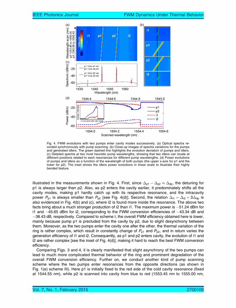
illustrated in the measurements shown in Fig. 4. First, since �p1 ��p2 � �dp, the detuning forp1 is always larger than p2. Also, as p2 enters the cavity earlier, it predominately shifts all thecavity modes, making p1 hardly catch up with its respective resonance, and the intracavitypower Pp1 is always smaller than Pp2 [see Fig. 4(d)]. Second, the relation �i1 ¼ �i2 þ 3�dp isalso evidenced in Fig. 4(b) and (c), where i2 is found more inside the resonance. The above twofacts bring about a much stronger production of i2 than i1. The maximum power is �51.24 dBm fori1 and �45.65 dBm for i2, corresponding to the FWM conversion efficiencies of �43.34 dB and�38.43 dB, respectively. Compared to scheme I, the overall FWM efficiency obtained here is lower,mainly because pump p1 is precluded from the cavity by p2, due to slight desynchrony betweenthem. Moreover, as the two pumps enter the cavity one after the other, the thermal variation of thering is rather complex, which result in constantly change of Pp1 and Pp2, and in return varies thegeneration efficiency of i1 and i2. Consequently, as p1 and p2 enters cavity, the evolution of i1 andi2 are rather complex [see the inset of Fig. 4(d)], making it hard to reach the best FWM conversionefficiency.
Comparing Figs. 3 and 4, it is clearly manifested that slight asynchrony of the two pumps canlead to much more complicated thermal behavior of the ring and prominent degradation of theoverall FWM conversion efficiency. Further on, we conduct another kind of pump scanningscheme where the two pumps enter resonances from the opposite directions (as shown inFig. 1(e) scheme III). Here p1 is initially fixed to the red side of the cold cavity resonance (fixedat 1544.55 nm), while p2 is scanned into cavity from blue to red (1553.45 nm to 1555.00 nm,
Fig. 4. FWM evolutions with two pumps enter cavity modes successively. (a) Optical spectra re-corded synchronously with pump scanning. (b) Close-up images of spectra variations for the pumpsand generated idlers. The green dashed line highlights the evolution deviation of pumps and idlers.(c) Detailed spectra at two most heuristic pump wavelengths, showing that two idlers can locate atdifferent positions related to each resonances for different pump wavelengths. (d) Power evolutionsof pumps and idlers as a function of the wavelength of both pumps (the upper x-axis for p1 and thelower for p2). The inset shows the idlers power evolutions in linear scale to illustrate their highlybended feature.
Vol. 7, No. 1, February 2015 2700109
IEEE Photonics Journal FWM Dynamics Under Thermal Behavior

with 1 pm step size). The experimental results are summarized in Fig. 5, it is observed that thepump evolutions significantly deviate from the typical ‘thermal triangle’, indicating even morecomplex thermal dynamics than scheme I and II. In particular, as p2 shifts the cavity resonancestoward the longer wavelength, the red-shifted resonance encounters p1 at point ‘a’ as labeled inFig. 5(d), and the intracavity power begins to increase in acceleration. Importantly, since p1 is inthe red-detuning region (thermally unstable), it pulls the cavity resonances to longer wave-lengths very quickly that the scanning speed of p2 becomes slower than the speed of thermalshift, forcing p2 to leave the cavity. As the result, during this period the generation of i2 de-creases while i1 increases. Still, we have �p1 ��p2 ¼ �dpðtÞ þ�np1 ��np2, but now �dp and�np1 ��np2 changes dramatically, hence �i1 and �i2 do not have a fixed relationship [seeFig. 5(b) and (c)]. At point ‘b,’ p1 reaches its corresponding zero-detuning while p2 is still blue-detuned, and the power of i1 is still much higher than i2. Later on, as p2 keeps heating the ring,p1 crosses into the blue-detuning region. During this stage, p2 starts to go in resonances whilep1 goes off. Such an opposite action of p1 and p2 retards the thermal shift of cavity resonancesbetween point ‘c’ and ‘d’ [as highlighted in Fig. 5(b)], bringing about a section of uniform andstable evolutions of p1/p2 as well as i1/i2, within which the powers of i1 and i2 are maximized.After the point ‘d,’ p2 again speeds up entering resonance until point ‘e’ and afterward goesout from the red-detuning region, whilst p1 goes out from the blue-detuning region, and theFWM process comes to a halt. During the whole process with seriously convolved thermal andnonlinear effects, the maximum powers (conversion efficiencies) for i1 and i2 are �47.08 dBm(�39.54 dB) and �46.43 dBm (�39.28 dB), respectively, yet they are inferior to the perfor-mance of scheme I.
Fig. 5. FWM evolutions with two pumps enters cavity modes in different directions, where p1 isfixed, whereas p2 is scanned through its corresponding resonance. (a) Optical spectra recordedsynchronously with pump scanning. (b) Close-up images of spectra variations for the pumps andgenerated idlers. (c) Detailed spectra at three different pump wavelengths, showing that the idlerslocations related to cavity resonances exhibit complex changes. (d) Power evolutions of pumps andidlers as a function of the wavelength of p2.
Vol. 7, No. 1, February 2015 2700109
IEEE Photonics Journal FWM Dynamics Under Thermal Behavior

The series of experiments presented above demonstrate the tight connection between thedual-pump thermal behavior of silicon microring resonator and the FWM process within it. Thethermal shift of cavity resonances not only modifies intracavity pump powers, but also influencesthe phase-matching conditions between pumps and idlers, and the resonant enhancement ofthe generated idlers, and all these parameters together decide the FWM efficiency. Amongstour demonstrations, best FWM efficiencies are achieved by utilizing synchronous pump scan-ning scheme, which benefits from the most uniform and effective thermal-locking of both pumps.Asynchrony of pumps significantly complicates the thermal behaviors of the microring resonatorand severely degrades FWM efficiency. As shown in Figs. 4 and 5, with badly configured initialconditions, regular input pump scanning leads to rather irregular idler evolutions. There mightbe some points within the tortuous development of idlers where favorable FWM efficiency couldbe obtained, but such a critical point is either scarce or arduous to access.
In addition, we note that traditionally adopted methodology for FWM process is to individuallytune the pumps to resonance, alter one or both pump powers, record the idler sidebands, andcalculate the conversion efficiency [6], [16]. However, according to our discussion above, it ispostulated that the alteration of pump powers can also induce thermal variation of the microring,making it difficult to accurately extract the pure parametric conversion efficiency. Fig. 6 givestwo demonstrations following the conventional measurement steps. For comparison we deliber-ately put pumps at different initial positions inside the cavity resonance, as schematically shownin the inset of Fig. 6(c) and (d). Then we sweep the power of pump p2 from 1 mW to 27 mW at100 �W step. It is observed that the change of the input pump power indeed shifts the cavityresonance, affects the intracavity power buildup for p1 and p2, and modifies the generation ofFWM idlers. Particularly, as shown in Fig. 6(a) and (c), the increase of input pump power pullsthe cavity modes to longer wavelengths so that p1 leaves the cavity, and therefore the gener-ations of FWM idler waves are quite weak. On the contrary, for the case shown in Fig. 6(b),p1 and p2 both are initially red-detuned, so that the increase of Pp2 leads to the increase ofPp1, and both idlers grow rapidly. Beyond the point ‘a’ in Fig. 6(d), p2 crosses into the blue-detuning region ahead of p1, then the power change of the two pumps once again becomes
Fig. 6. FWM dynamics with increasing pump power, with different initial pump wavelength configu-rations. (a) and (b) Recorded optical spectra synchronously with the pump power variation. The in-set map evidences the thermal shift of the cavity resonance with specified color scale. Dashed(solid) lines represent the beginning (end) of pump power scanning. (c) and (d) Power evolutionsfor pumps and generated idlers recorded at the through port of the resonator, as a function of inputpower of the pump p2.
Vol. 7, No. 1, February 2015 2700109
IEEE Photonics Journal FWM Dynamics Under Thermal Behavior

quite entangled. After examining these curves it is apparent that, as pump power being modi-fied, the evolution curves of idlers do not merely reflect the change of parametric conversionefficiency, but also involve contributions from the thermal dynamics of the ring. These resultsagain remind us to pay better attentions to the thermal kinetics of micro-resonators while in-vestigating any nonlinear processes inside them.
3. ConclusionTo conclude, we conducted detailed characterizations of the FWM effect in a silicon microringresonator, and demonstrated that the thermal behavior of the microring in the presence of twointense pumps can prominently modify the intracavity pump power distributions and substan-tially impact FWM performances. Nevertheless, relatively high conversion efficiencies (about�37 dB in a 10-micron-radius ring) are achieved with a synchronous pump scanning scheme,which we suggested as the most applicable method for resonantly enhanced FWM in micro-resonators. Finally, it is worth mentioning that, besides thermal resonance shifts, the cavitymodes of silicon resonators are also subject to the influence of free-carrier plasma dispersion,which is of lower intensity but much faster response time compared to thermal process. As wefocused here on the steady-state FWM performances using continuous-wave pumps with powerlevel G þ10 dBm, free-carrier effects were neglected. However, it is interesting and important toinvestigate the impact of free-carrier dynamics on FWM as well as other nonlinear processes insilicon resonators that involve high bit-rate data signals with high pulse peak power, which willbe presented in our subsequent work.
References[1] J. Niehusmann et al., “Ultrahigh-quality-factor silicon-on-insulator microring resonator,” Opt. Lett., vol. 29, no. 24,
pp. 2861–2863, May 2004.[2] Y. Ding et al., “Ultra-wide band signal generation using a coupling-tunable silicon microring resonator,” Opt. Exp.,
vol. 22, no. 5, pp. 6078–6085. Mar. 2014.[3] L. D. Tzuang, M. Soltani, Y. H. D. Lee, and M. Lipson, “High RF carrier frequency modulation in silicon resonators
by coupling adjacent free-spectral-range modes,” Opt. Lett., vol. 39, no. 7, pp. 1799–1802, Mar. 2014.[4] M. Xiong et al., “All-optical 10 Gb/s AND logic gate in a silicon microring resonator,” Opt. Exp., vol. 21, no. 22,
pp. 25772–25779, Oct. 2013.[5] B. G. Lee, B. A. Small, K. Bergman, Q. Xu, and M. Lipson, “Transmission of high-data-rate optical signals through a
micrometer-scale silicon ring resonator,” Opt. Lett., vol. 31, no. 18, pp. 2701–2703, Aug. 2006.[6] A. C. Turner, M. A. Foster, A. L. Gaeta, and M. Lipson, “Ultra-low power parametric frequency conversion in a silicon
microring resonator,” Opt. Exp., vol. 16, no. 7, pp. 4881–4887, Mar. 2008.[7] Y. H. Wen et al., “All-optical control of an individual resonance in a silicon microresonator,” Phys. Rev. Lett., vol. 108,
no. 22, Jun. 2012, Art. ID. 223907.[8] S. Chen, L. Zhang, Y. Fei, and T. Cao, “Bistability and self-pulsation phenomena in silicon microring resonators
based on nonlinear optical effects,” Opt. Exp., vol. 20, no. 7, pp. 7454–7468, Mar. 2012.[9] T. Carmon, L. Yang, and K. J. Vahala, “Dynamical thermal behavior and thermal self-stability of microcavities,”
Opt. Exp., vol. 12, no. 20, pp. 4742–4750, Oct. 2004.[10] L. Zhou, H. Zhu, H. Zhang, and J. Chen, “Photoconductive effect on p-i-p micro-heaters integrated in silicon microring
resonators,” Opt. Exp., vol. 22, no. 2, pp. 2141–2149, Jan. 2014.[11] Q. Xu and M. Lipson, “Carrier-induced optical bistability in silicon ring resonators,” Opt. Lett., vol. 31, no. 3, pp. 341–
343, Feb. 2006.[12] M. Erkintalo, Y. Q. Xu, S. G. Murdoch, J. M. Dudley, and G. Genty, “Cascaded phase matching and nonlinear sym-
metry breaking in fiber frequency combs,” Phys. Rev. Lett., vol. 109, no. 22, Nov. 2012, Art. ID. 223904.[13] A. A. Savchenkov et al., “Kerr frequency comb generation in overmoded resonators,” Opt. Exp., vol. 20, no. 24,
pp. 27290–27298, Nov. 2012.[14] H. Zhou, K. Qiu, and F. Tian, “Optimized all-optical amplitude reshaping by exploiting nonlinear phase shift in fiber
for degenerated FWM,” Chin. Opt. Lett., vol. 10, no. 5, May 2012, Art. ID. 050601.[15] T. J. Kippenberg, S. M. Spillane, and K. J. Vahala, “Kerr-nonlinearity optical parametric oscillation in an ultrahigh-Q
toroid microcavity,” Phys. Rev. Lett., vol. 93, no. 8, Aug. 2004, Art. ID. 083904.[16] R. Salem et al., “Signal regeneration using low-power four-wave mixing on silicon chip,” Nat. Photon., vol. 2, no. 1,
pp. 35–38, May 2008.[17] W. Pernice, M. Li, and H. Tang, “Time-domain measurement of optical transport in silicon micro-ring resonatorss,”
Opt. Exp., vol. 18, pp. 18438–18452, Aug. 2010.[18] L. Yin and G. P. Agrawal, “Impact of two-photon absorption on self-phase modulation in silicon waveguides,” Opt.
Lett., vol. 15, pp. 2031–2033, Jul. 2007.
Vol. 7, No. 1, February 2015 2700109
IEEE Photonics Journal FWM Dynamics Under Thermal Behavior


![[3] Neokosmidis Techniques for FWM Suppresion](https://static.fdocuments.us/doc/165x107/577cde0b1a28ab9e78ae468d/3-neokosmidis-techniques-for-fwm-suppresion.jpg)