FWA DELINEATION SAMPLING PLAN FIELDS BROOK SITE …
28
DIAFT IEPORT FWA DELINEATION SAMPLING PLAN FIELDS BROOK SITE ASHTABULA, OHIO Prepared for Fields Brook Action Group Ashtabula, Ohio January 31, 1997 Woodward-Clyde ^ 30775 Bainbridge Rd. Solon, Ohio 44139 (216)349-2708 86C3609S
Transcript of FWA DELINEATION SAMPLING PLAN FIELDS BROOK SITE …

D I A F T I E P O R T
FWA DELINEATION SAMPLINGPLAN
FIELDS BROOK SITEASHTABULA, OHIO
Prepared forFields Brook Action GroupAshtabula, Ohio
January 31, 1997
Woodward-Clyde ^
30775 Bainbridge Rd.Solon, Ohio 44139(216)349-270886C3609S

TABLE 6IC8NTENTS
Qortinn 1
Section 2
Section 3Section 4
Additional Data...............................................................................
Floodplain Exposure Units ...........................................................2.1 Delineation Sampling Program ...............................
Laboratory Analysis ......................................................................Samolina Activities ........................................................................
.....................................1-1
.....................................2-1
...............................2-1
.....................................3-1
.....................................4-1
List of TablesTable 1 Summary of Floodplain SamplingTable 2 Summary of Analytical ParametersTable 3 Schedule of Delineation Sampling Plan
List of FiguresFigure 1 FWA Delineation Sampling Locations, FEU 2AFigure 2 FWA Delineation Sampling Locations, FEU 2BFigure 3 FWA Delineation Sampling Locations, FEU 3Figure 4 FWA Delineation Sampling Locations, FEU 4Figure 5 FWA Delineation Sampling Locations, FEU 6Figure 6 FWA Delineation Sampling Locations, FEU 8
List of AppendicesAppendix A January 22, 1997 USEPA LetterAppendix B QAPjP Addendum
WoOdWard-Clyde W L:\337FB\86C3609S\SAMP111B.DOC\31-Jan-97\SOL i

SECTIONONE________________Additional Data Needs
As part of the Phase III FWA investigation, samples were collected from surface soils within theFields Brook floodplain. This sampling was undertaken to provide additional characterization datato perform more representative ecological and baseline human health risk assessments, to obtain asufficient number of samples to develop a statistical database, and to obtain additional data toevaluate the lateral extent of constituents of concern (COCs) within floodplain exposure units(FEUs) for better definition of remedial alternatives in the Feasibility Study. As described in theOctober 1996 FWA FS, Alternative VII has been proposed by USEPA to be the preferredalternative and consists of hydric compatible soil cover, excavation, backfill, and on-site disposal.Response areas considered in this alternative considered PCB and hexachlorobenzene (HCB) asthe principal COCs. This alternative considers the following targets: cover (6-30 ppm PCBand/or 6-80 ppm HCB) and excavation (> 30 ppm PCB and/or > 80 ppm HCB) scenarios inresidential FEUs, and an excavation (> 50 ppm PCB and/or > 200 ppm) scenario in industrialFEUs.
In order to further define the response areas that were developed in the FWA FS for AlternativeVII, it is necessary to further delineate the lateral extent of the COCs to support the designprocess. This will ensure that response areas are accurately depicted and also help to preventunnecessary remedial activities at clean areas.
Therefore, a delineation sampling program (DSP) has been planned and supported by USEPA.The sampling strategy will be based on a systematic approach that includes additional soil surfacesampling in 50 ft grid intervals within the floodplain reaches of Fields Brook. This samplingprogram will supplement the systematic sampling completed during Phase III, and incorporatesthe comments of the USEPA January 22, 1997 letter.
The sampling approach described in the following sections provides for approximately 530additional surface soil samples in FEU 2A, FEU 2B, FEU 3, FEU 4, FEU 6, and FEU 8. Thenumber of samples proposed is considered adequate by the USEPA for further delineation ofPCBs in both non-response areas which have not been sampled and the remedial response areaswhich were identified in FWA Alternative VII.
Woodward-Clyde V L:\337FB\86C3609S\SAMP111B.DOC\31-Jan-97VSOL 1-1

SECTIONTWQ______________Floodplaln Exposure Units
The sampling areas are the same FEUs described in "Phase III Floodplain Sampling Design,Fields Brook Site, Ashtabula, Ohio" (WCC, October 1994), which have been developed inaccordance with "Methods for Evaluating the Attainment of Cleanup Standards" (USEPA, 1989).The following sections describe the approach that will be used during the delineation samplingprogram.
2.1 DELINEATION SAMPLING PROGRAMA 50 ft grid interval was established within the FWA. Soil samples will be collected within eachinterval.
The following criteria were used in selecting delineation sampling locations outside the designatedremedial response areas:
• If a sampling grid interval is more than 1250 sq ft (50% of the total potential area) and nosample has been collected in that grid interval, then a delineation sample will be collected.
• If a sampling grid interval is less than 1250 sq ft or data has already been collected for thatgrid interval, then no further sampling will be performed at that location.
In the designated remedial response areas, sampling locations were selected in order to furtherdelineate the boundaries of these areas. A summary of the existing and proposed floodplainsampling locations for each of the FEUs is provided in Table 1. Existing and proposed floodplainsampling locations are shown on Figures 1 through 6.
WllU JMWU ClydO W L:\337FB\86C3609S\SAMP111B.DOC\31-Jan-97\SOL 2-1
SECTI8HTHREE_______________laboratory Analysis
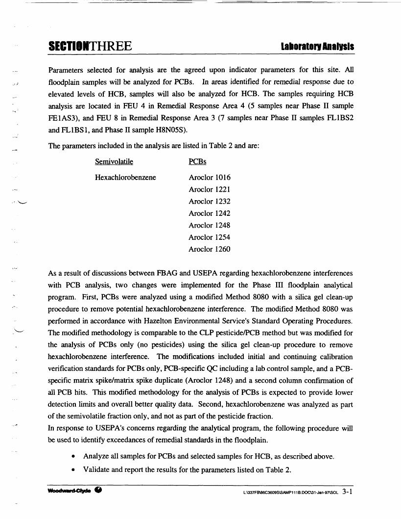
Parameters selected for analysis are the agreed upon indicator parameters for this site. Allfloodplain samples will be analyzed for PCBs. In areas identified for remedial response due toelevated levels of HCB, samples will also be analyzed for HCB. The samples requiring HCBanalysis are located in FEU 4 in Remedial Response Area 4 (5 samples near Phase II sampleFE1AS3), and FEU 8 in Remedial Response Area 3 (7 samples near Phase II samples FL1BS2and FL1BS1, and Phase II sample H8N05S).
The parameters included in the analysis are listed in Table 2 and are:
Semivolatilc PCBs
Hexachlorobenzene Aroclor 1016Aroclor 1221Aroclor 1232Aroclor 1242Aroclor 1248Aroclor 1254Aroclor 1260
As a result of discussions between FBAG and USEPA regarding hexachlorobenzene interferenceswith PCB analysis, two changes were implemented for the Phase III floodplain analyticalprogram. First, PCBs were analyzed using a modified Method 8080 with a silica gel clean-upprocedure to remove potential hexachlorobenzene interference. The modified Method 8080 wasperformed in accordance with Hazelton Environmental Service's Standard Operating Procedures.The modified methodology is comparable to the CLP pesticide/PCB method but was modified forthe analysis of PCBs only (no pesticides) using the silica gel clean-up procedure to removehexachlorobenzene interference. The modifications included initial and continuing calibrationverification standards for PCBs only, PCB-specific QC including a lab control sample, and a PCB-specific matrix spike/matrix spike duplicate (Aroclor 1248) and a second column confirmation ofall PCB hits. This modified methodology for the analysis of PCBs is expected to provide lowerdetection limits and overall better quality data. Second, hexachlorobenzene was analyzed as partof the semivolatile fraction only, and not as part of the pesticide fraction.In response to USEPA's concerns regarding the analytical program, the following procedure willbe used to identify exceedances of remedial standards in the floodplain.
• Analyze all samples for PCBs and selected samples for HCB, as described above.
• Validate and report the results for the parameters listed on Table 2.
L:\337FB\86C3609SVSAMP111B.DOC\31-Jan-97\SOL 3~1

SECTIOMTHREE_______________Laboratory AnalysisThe FWA delineation analytical methodology for PCBs will use the laboratory modificationdescribed above. The SOU QAPjP addendum submitted to USEPA on November 8, 1994, isprovided in Appendix B of this DSP.
WDOd¥«d-Clyde W L:\337FB\86C3609S\SAMP111B.DOC\31-Jan-97\SOL 3~2

SECTIONFOUR________________Sampling ActMUes
SurveyingPrior to entering the field, coordinates for all delineation sampling points will be pulled from theAutoCAD drawing and a list will be generated. Using GPS (Global Positioning System)equipment, a single surveyor will access the existing site grid by occupying previous surveycontrol points and bench marks. A stake, marked with the corresponding sample number, willthen be placed on each of the proposed sampling locations. The horizontal location and verticalelevation of each staked point will be recorded using the electronic data collector whichaccompanies the GPS equipment. The surveyor will have at least a one day lead on the samplingcrew. If the sampling crew does not collect a sample at the staked location, they will record theactual sample location by measuring and recording the bearing and distance from the staked pointusing a compass and tape measure.
Sample LabelingEach sample collected will be assigned a unique sample identification number. The six charactersample identification number will consist of the following parts:
• Sample Matrix Code D-Delineation sample
• Sample Location 1 = FEU 1,2 = FEU 2, ...8 = FEU 8.
• Sample Number 01,02...n, n = number of samples in the FEU.
• Sample Type S = Soil, D = Duplicate, M = Matrix Spike, Matrix Spike Duplicate
Sample Collection and Quality Assurance/Quality Control (QA/QC)Surface soil samples will be collected using the stake which has been used to mark the samplinglocation. Field personnel will describe and photograph the sampling location. All sampling datawill be entered into a bound field log book.
•••*! ^
Surface soil samples will be collected in the following manner:
• Soil samples will be collected from the top 6 inches of soil after vegetation and large roots areremoved from the sampling location. The sampling area will be approximately 1 ft by 1 ft.
• A sufficient amount of soil will be collected for the PCB and/or HCB analyses. The soil will behomogenized in place using the stake, and placed in the appropriate laboratory containers.
• Duplicate and Matrix Spike/Matrix Spike Duplicate (MS/MSD) samples will be collected bydistributing soil equally into two sets of sample containers at a frequency of 1 per 20 samples
L:\337FB\86C3609S\SAMP111B.DOC\31-Jan-97\SOL 4-1

SECTIOHFQUR________________Sampllm Activities
collected, as described in the SOU QAPjP. MS/MSD samples will be prepared by thelaboratory from the environmental samples collected by the field personnel. These samples willbe analyzed for SVOCs (as appropriate) and PCBs to evaluate whether matrix spikerecoveries falling outside the acceptable windows are attributable to sample matrixinterferences or to laboratory analytical errors.
• In order to minimize cross contamination between sample locations, field personnel willchange surgical gloves between each sampling event.
• Surface soil samples will be analyzed for parameters identified in Table 2. Sample containerswill be stored in iced, insulated coolers with appropriate chain-of-custody documentation.Samples will be sent to the laboratory via overnight courier.
• The minimum sample size for each analysis requested is 50 g. Therefore, each sample will beplaced in an 4 oz wide mouth glass jar with a Teflon lining for shipment to the analyticallaboratory.
Collection of field blanks and inclusion of trip blanks in sample shipments is not required for soilsamples.
DecontaminationDecontamination of personnel and equipment will be performed to prevent possible crosscontamination and transport of contaminants off site or between work areas.
Personnel DecontaminationSampling personnel will be required to use clean gloves while collecting each sample. Non-disposablepersonal protective gear will be decontaminated before personnel enter the support area. Thepersonnel decontamination procedure is as follows:
1. Place equipment and/or samples in designated area; move to next station.
2. Remove outer coveralls and booties and place in plastic bags .
3. Wash boots and outer gloves using soap (Alconox or equivalent), and potable waterrinse. Place gloves and disposable overboots in plastic bags.
4. Remove respirator, if used, sanitize, and store in appropriate place.
5. Remove and discard inner gloves and wash hands and face.
6. Shower entire body, including hair, at the end of work day.
L:\337FB\86C3609SVSAMP111B.DOC\31-Jan-97VSOL 4~2
SECTIONFQUR________________Sampling Activities
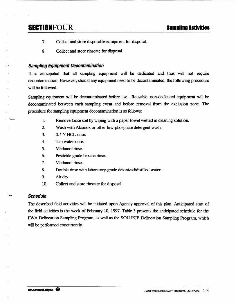
7. Collect and store disposable equipment for disposal.
8. Collect and store rinseate for disposal.
Sampling Equipment DecontaminationIt is anticipated that all sampling equipment will be dedicated and thus will not requiredecontamination. However, should any equipment need to be decontaminated, the following procedurewill be followed.
Sampling equipment will be decontaminated before use. Reusable, non-dedicated equipment will bedecontaminated between each sampling event and before removal from the exclusion zone. Theprocedure for sampling equipment decontamination is as follows:
1. Remove loose soil by wiping with a paper towel wetted in cleaning solution.2. Wash with Alconox or other low-phosphate detergent wash.3. O.lNHCLrinse.4. Tap water rinse.5. Methanol rinse.6. Pesticide grade hexane rinse.7. Methanol rinse.8. Double rinse with laboratory-grade deionized/distilled water.9. Air dry.10. Collect and store rinseate for disposal.
ScheduleThe described field activities will be initiated upon Agency approval of this plan. Anticipated start ofthe field activities is the week of February 10, 1997. Table 3 presents the anticipated schedule for theFWA Delineation Sampling Program, as well as the SOU PCB Delineation Sampling Program, whichwill be performed concurrently.
L:\337FB\B6C3609S\SAMP111B.CX>C\31-Jan-97\SOL 4-3

Tables

Woodward-Clyde
TABLE 1SUMMARY OF FLOODPLAIN SAMPLING
FIELDS BROOKASHTABULA, OHIO
Floodplain Number ofExposure Phase IUnit Samples
FEU2A
FEU2B
FEU 3
FEU 4
FEU 6
FEUS
TOTAL
1
2
0
1
4
3
11
Number ofPhase IISamples
3
15
6
6
10
18
58
Number of Number ofPhase I SCRI Phase III
Samples Samples
0
0
0
2
0
3
5
8
14
29
21
26
18
116
Number ofDelineation
Samples
34
103
80
135
81
96
529
TotalNumber
of Samples
46
134
115
165
121
138
719
L:\337FB\86C3609S\SAMPSIZE.XLS 1/31/97

Woodward-Clyde
TABLE 2SUMMARY OF ANALYTICAL PARAMETERSFWA DELINEATION SAMPLING PROGRAM
FIELDS BROOKASHTABULA, OHIO
Si'iimolatik's
Hexachlorobenzene (HCB)Pnhdiinrinak'd Hiphenyls (PCHs)
Aroclor 1016Aroclor 1221Aroclor 1232Aroclor 1242Aroclor 1248Aroclor 1254Aroclor 1260
L:\337FBV86C3«)9S\TABLE2.DOC 1/31/97

Figures

MATCH LINE - SEE FEU2B FIGURES
——————————— LEGEND ————————————
"«•*•—- 100 YEAR FLOOOPLAIN BOUNDARYFUD7IOZS-11 * SAMPLE: PHASE I FLOOOPLAIN SOIL
aiBS6+ SAMPLE: PHASE D SURFACE SOIL• SAMPLE: PHASE HI FLOODPLAIN SOIL• SAMPLE: PHASE I SURFACE SOIL SOURCE CONTROL• DELINEATION SAMPLES (PCB)
1 REMEDIAL RESPONSE AREAS
PCB CONCENTRATION > 30 eng/kgHC8 CONCENTRATION > 80 mg/kg
,————, r COVER AREA•.-.-.•.•.V. PCB CONCENTRATION 6-30 mg/kg
1——'—' HCB CONCENTRATION 6-80 mg/kg
NOTE BASE MAP PREPARED BY KUCERA INTERNATIONALDATE OF AERIAL PHOTOGRAPHY 4-18-87
0 30 60 120 180
Woodward-ClydeConsultantsEnojncerng ft sciences Opp6ed to the earth 4 its environment
30775 Bainbridge Road, Suite 200Solon, Ohio 44139
CLIENT: FIELDS BROOK
LOCATION: ASHTABULA, OHIO
FLOODPLAIN EXPOSURE UNIT 2AFWA DELINEATION SAMPLE LOCATIONS
ALTERNATIVE VIICHECKED BY: PROJECT NO: DATE:
MMS NES 86C3609S 1 -28-97

MATCH LINE - v— £ FEU2A FIGURES— -- " r——j-
D
100 YEAR FLOOOPLAM BOUNDARY'loo-ii A SAMPLE: PHASE I FUMDPLAM SOLn.1M+ SAMPLE: PHASE H SURFACE SOL
• SAMPLE: PHASE • FLOOOPLAM SOL• SAMPLE: PHASE I SURFACE SOL SOURCE CONTROL$• DEUNEATION SAMPLES (PCB)
REMEDIAL RESPONSE AREAS
Woodward-ClydeConsultantsEngineering ft scanctt applied to the eorth ft to environment
30775 Bainbridge Road, Suite 200Solon, Ohio 44139
8FIELDS BROOK
\f EXCAVATION AREAPCS CONCENTRATION > 30 mg/kgHC8 CONCENTRATION > 80 Big/kg
er COVER AREAPCB CONCENTRATION 6-30 mg/kgHC8 CONCENTRATION 6-80 mg/kg
NOTE: BASE MAP PREPARED BY KUCERA INTERNATIONALDATE OF AEMAL PHOTOCRAPHY 4-18-87
LOCATION: ASHTABULA. OHIO
FLOODPLAIN EXPOSURE UNIT 2BFWA DELINEATION SAMPLE LOCATIONS_____ALTERNATIVE VII_____DRAWN BY: CHECKED BY: PROJECT NO: DATE: FIGURE NO:
BGK NES 86C3609S 1-29-97 2

LEGEND~~r—- 100 YEAR FLOODPLAIN BOUNDARY
FL07102S-11 A SAMPLE: PHASE I FLOOOPLAIN SOILFL1BS6+ SAMPLE: PHASE II SURFACE SOIL
• SAMPLE: PHASE III FLOOOPLAIN SOIL• SAMPLE: PHASE I SURFACE SOIL SOURCE CONTROL$ DELINEATION SAMPLES
REMEDIAL RESPONSE AREAS
12" EXCAVATION AREAPCS CONCENTRATION > 30 mg/kgHCB CONCENTRATION > 80 mg/kg
ff COVER AREAPCB CONCENTRATION 6-30 mg/kgHCB CONCENTRATION 6-80 mg/kg
0 SO 60 120 180
Woodward-ClydeConsultantsEngineering ft ttiences oppM to the eorth ft its environment
30775 Bainbridge Road. Suite 200Solon. Ohio 44139
FIELDS BROOK
LOCATION: ASHTABULA, OHIO
FLOODPLAIN EXPOSURE UNIT 3FWA DELINEATION SAMPLE LOCATIONS
ALTERNATIVE VIIDRAWN BY: CHECKED BY: PROJECT NO: DATE: FIGURE NO:
MMS NES 86C3609S 1-29-97 3
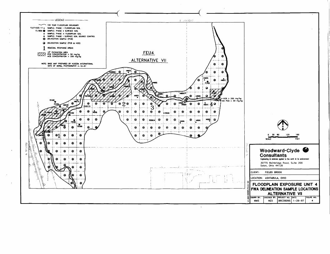
——————————— LEGEND ————————————
—-••—- 100 YEAR FLOODPLAIN BOUNDARYFL07102S-11 A SAMPLE: PHASE I FLOOOPLAJN SOL
SAMPLE: PHASE II SURFACE SOILSAMPLE: PHASE III FLOOOPLAIN SOILSAMPLE: PHASE I SURFACE SOIL SOURCE CONTROLDELINEATION SAMPLE (PCS)
DELINEATION SAMPLE (PCB A HCB)
REMEDIAL RESPONSE AREAS
\T EXCAVATION AREAPCB CONCENTRATION > 50 mg/kgHCB CONCENTRATION > 200 mg/kg
ALTERNATIVE VIINOTE: BASE MAP PREPARED BY KUCERA INTERNATIONAL
DATE OF AERIAL PHOTOGRAPHY 4-18-87
HCB > 200 mg/kgNO PCB > 50 mg/kg
Woodward-ClydeConsultantsEngineering 4 wences oppfied to the earth 4 its environment
30775 Bainbridge Road, Suite 200Solon, Ohio 44139
CLIENT: FIELDS BROOK
LOCATION: ASHTABULA, OHIO
FLOODPLAIN EXPOSURE UNIT 4FWA DELINEATION SAMPLE LOCATIONS
ALTERNATIVE VIIDRAWN BY: I CHECKED BY: I PROJECT NO: I DATE: [FIGURE NO:
MMS I NES |s6C3609s| 1-29-97 I 4

——————————— LEGEND ————————————
~~r—- 100 YEAR FLOODPLAIN BOUNDARY
FU07102S-11 * SAMPLE: PHASE I FLOODPLAIN SOILaiBS6^ SAMPLE: PHASE II SURFACE SOIL
• SAMPLE: PHASE III ROODPLAIN SOIL• SAMPLE: PHASE I SURFACE SOIL SOURCE CONTROL
•$• DELINEATION SAMPLE
1 REMEDIAL RESPONSE AREAS
12" EXCAVATION AREAPCB CONCENTRATION > 50 mg/kgHCB CONCENTRATION > 200 mg/kg
NOTE: BASE MAP PREPARED BY KUCERA INTERNATIONALDATE OF AERIAL PHOTOGRAPHY 4-18-87
Woodward-ClydeConsultantsEngineering k sciences applied to the «arth 4 its environment
30775 Bainbridge Road, Suite 200Solon, Ohio 44139
CLIENT: FIELDS BROOK
LOCATION: ASHTABULA, OHIO
FLOODPLAIN EXPOSURE UNIT 6FWA DELINEATION SAMPLE LOCATIONS_____ALTERNATIVE VII____DRAWN BY: CHECKED BY: PROJECT NO: DATE: FIGURE NO:
MMS NES 86C3609S 1-30-97 5

LEGEND100 YEAR FLOOOPLAIN BOUNDARYSAMPLE: PHASE I FUX30PLAIN SOILSAMPLE: PHASE I SURFACE SOIL
• SAMPLE: PHASE IK FLOODPLAJN SOIL• SAMPLE: PHASE I SURFACE SON. SOURCE CONTROL
•$ DELINEATION SAMPLE (PCS)9 DELINEATION SAMPLE (PCS AND HCB)
1 REMEDIAL RESPONSE AREAS
IT EXCAVATION AREAPCB CONCENTRATION > 50 ma/kgHCB CONCENTRATION > 200
180-4FEET
NOTE: BASE MAP PREPARED BY KUCERA INTERNATIONALDATE OF AERIAL PHOTOGRAPHY 4-18-87
Woodward-ClydeConsultantsEngineering ft tamos oppfej to the eortti » its environment
30775 Boinbridge Rood. Suite 200Solon, Ohio 44139
CLIENT: FIELDS BROOK
LOCATION: ASHTABULA. OHIO
FLOODPLAIN EXPOSURE UNIT 8FWA DELINEATION SAMPLE LOCATIONS
ALTERNATIVE VIIDRAWN BY: CHECKED BY: PROJECT NO: DATE: FIGURE NO:
MMS NES 86C3609S 1-28-97 6

Appendix A

StNT BY'U.S. tTA I 1-22-97 ; 5:50PM ; SUPERFUND DIVISION- 216 349 1514;* 2/ 2
^ \̂ UNITED STATES ENVIRONMENTAL PROTECTION AGENCYREGIONS .'
77 WEST JACKSON BOULEVARDCHICAGO, IL 60004-3690
Via Facsimile
January 22, 1997i. * ,T j i_ i_ REPLY TO THE ATTENTION OF:Joseph A. Heimbuch
DeMa'ximis, Inc.3148-A Southgate CircleSarasota, PL 34239
RBt Fields Brook FWA Delineation SamplingDear Mr. Heimbuch:
This letter responds to FBAG's 1/17/97 letter regardingschedule and the floodplain/wetlands area (FWA) delineationsampling plan. Your letter notes that failure to resolve thedelineation sampling issue will result in delays to theconstruction of the remedy.
In response, EPA is also concerned regarding the overallschedule, and has thoroughly considered this issue since thereceipt of FBAG's 12/20/96 response to EPA's 12/6/96 commentletter to this issue. For reasons noted in part in EPA's 12/6/96letter, and as discussed during recent telephone communicationsbetween Lee Gelman and Joseph Lonardo, EPA requests that the FWAdelineation sampling plan be revised to indicate that one PCBsample will be taken and analyzed within each unsampled X50 footsquare grid box indicated in the 12/2 figures for all FWA areasdowngradient of the EU8 CUG exceedance areas. .FBAG may choosenot to do further sampling in existing areas slated for responseactions if those response areas would not be subject to change.However, if FBAG chooses to do additional sampling within anyplanned response area, the entire response area would need tohave 50' grid samples. EPA requests that FBAG re submit thedelineation sampling plan to be consistent with the abovecomments within two weeks. .
Also, to prevent further delays regarding other fieldworkwhich must be conducted prior to submit tal of the SOU 9p* design,EPA also requests that FBAG submit the Brook sediment delineation -,sampling plan which was discussed at the 9/26/96 i meeting withintwo weeks.
! I
If you have any questions regarding this letter, please Icontact me at (312) 353-9228. !
Edwad J. HanlonI
cc: R. Williams, OEPA M. Schmidt (facsimile)P. Felitti, ORC L. Gelman, DOJ

Appendix B

Woodward-ClydeEngineering « sciences appfied to the earth ft its environment
November 8, 199486C3609L
United States Environmental Protection AgencyRegion V (HSRM-6J)Ohio/Minnesota Remedial Branch77 West Jackson BoulevardChicago, IL 60604-3590
Attention: Mr. Edward J. Hanlon
Subject: Phase III Floodplain Sampling Design InvestigationQuality Assurance Project Plan AddendumFields Brook Superfund Site, Ashtabula, Ohio
Dear Mr. Hanlon:
This addendum to the Quality Assurance Project Plan (QAPP), Sediment Operable UnitDesign Investigation (SOU), Fields Brook Site (dated July 1993) is submitted to EPARegion V for approval as part of the Phase III Floodplain Sampling DesignInvestigation. The addendum consists of the following changes and additions to theSOU QAPP applicable to the Phase III field collection activities and laboratory analyses:
Section 3.4.2 Project Objectives
The project objectives for the Phase III Sampling Design Investigation are specified inSection 1.0 of the Phase III Sampling Design Work Plan.
Section 4.0 Project Organization and Responsibilities
Section 4.4 Responsibilities of Key WCC Personnel
Section 4.4 will be applicable to the Phase III Sampling program with the followingchanges:
Phase III Floodplain Sampling Design Investigation. Project Manager - Martin L.Schmidt is responsible for defining the Phase III project objectives, adhering toproject schedules, tracking the project budget and overseeing preparation andquality of the final reports.
FBJ3APP.ADN/86C3609/ November 7, 1994
Woodward-Clyde Consultants • A subsidiary of Woodward-Clyde Group, Inc.30775 Bainbrkjge Road, Suite 200 • Solon, Ohio 44139216-349-2708 • Fax 216-349-1514

Woodward-Clyde
Mr. Edward J. HanlonUnited States Environmental Protection AgencyNovember 8, 1994Page 2
Phase m Floodplain Sampling Design Investigation. Project Task Manager -Jennifer LeBlanc is responsible for overseeing the day-to-day field operations,project staffing, maintenance of the project administration and technical files,addressing issues of non-conformance. and ensuring proper validation,verification, and peer review of project task records.
Section 4.5 Laboratory Responsibilities and Key Personnel
Section 4.5 of the SOU QAPP is replaced with the following for the Phase III FloodplainSampling Design Investigation:
Hazleton Environmental Services (HES, Inc.) will perform the Phase III analyses of soils,sediments and water samples in accordance with the protocols specified in the SOUQAPP and this QAPP Addendum. The following key HES personnel will be involvedwith this project:
Mr. David Hills Vice Operations, Laboratory OperationsMs. Amy Austin Supervisor, Quality Assurance UnitMr. Todd Noltemeyer Supervisor, Pesticide Residue DepartmentMr. Harley Cliffs Supervisor, Mass SpectrometryMr. John Walton Supervisor, Inorganic ChemistryMs. Dawn Wheeler Supervisor, General Organics Group
Section 5.0 Quality Assurance Objectives for Measurement of Data
Section 5.4 Measurement Goals
The limits for percent recovery (%R) which show acceptable accuracy and the limits forrelative percent difference (RPD) which show acceptable precision for the inductivelycoupled plasma emission spectroscopy (ICP) analysis of metals to be used in the PhaseIII Sampling Design Investigation are listed in Table 5.3A of the SOU QAPP, dated July1993.
The accuracy (%R) and precision (RPD) limits for the analysis of polychlorinatedbiphenyls (PCBs) by modified EPA SW-846 Method 8080 (See attachment 1) are
FB_QAPPj\DN/86C3609/ November 7,1994
Woodward-Clyde Consultants

Appendix B

Woodward-Clyde
Mr. Edward J. HanlonUnited States Environmental Protection AgencyNovember 8, 1994Page 3
provided in Table 1 of this addendum.
Section 9.0 Analytical Procedures
The soil/sediment and water samples collected as part of the Phase III FloodplainSampling Design Investigation will be analyzed for the parameters specified in Section3.0 of the Phase III Sampling Design Investigation Work Plan. The samples will beanalyzed in accordance with the methods specified in the SOU QAPP and this QAPPAddendum.
Section 9.5.1.3 Organochlorine Pesticides and PCBs
Section 9.5.1.3 of the SOU QAPP (July 1993) shall be revised to read as follows:
Soil/sediment and water samples will be analyzed for organochlorine pesticides andmulti-component polychlorinated biphenyls (PCBs) using the methods in the ContractLaboratory Program (CLP) Statement of Work (SOW) for Organics Analysis, SOWOLMO.1.8 or more recent version as specified in Table 9-1 in the SOU QAPP (datedJuly 1993). Air samples will be analyzed for pesticides/PCBs by the method specifiedin Table 9-2 of the SOU QAPP. Reporting limits for the pesticides/PCBs analysis arelisted in Table 9-4c for water and soil/sediment samples and in Table 9-4j for airsamples.
A modified SW-846 Method 8080 will be used for analysis of soil/sediment and watersamples for PCBs only (no pesticides). The modifications include initial calibration andcontinuing calibration verification for PCBs only, PCB-specific quality control includinga laboratory control sample, a PCB-specific MS/MSD (Aroclor 1248), and a secondcolumn confirmation of PCB hits. A copy of the laboratory's Standard OperatingProcedures (SOP) for this method are contained in Attachments 1 and 2. The PCBs tobe analyzed and the reporting limits for these PCBs by modified SW-846 Method 8080are listed in Table 2 of this addendum. The laboratory will follow the QC level of effortspecified in Table 5-2 of the SOU QAPP.
Additionally, the laboratory will use the silica gel clean-up protocol contained inAttachment 3 on all soil/sediment and water sample extracts analyzed for
FB_QAPPj\DN/86C3609/ N'ovcmbcr 7, 1994
Woodward-Clyde Consultants
Woodward-Clyde
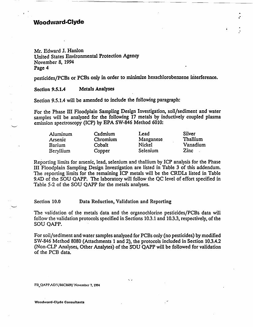
Mr. Edward J. HanlonUnited States Environmental Protection AgencyNovember 8, 1994Page 4
pesticides/PCBs or PCBs only in order to minimize hexachlorobenzene interference.
Section 9,5.1.4 Metals Analyses
Section 9.5.1.4 will be amended to include the following paragraph:
For the Phase III Floodplain Sampling Design Investigation, soil/sediment and watersamples will be analyzed for the following 17 metals by inductively coupled plasmaemission spectroscopy (ICP) by EPA SW-846 Method 6010:
Aluminum Cadmium Lead SilverArsenic Chromium Manganese ThalliumBarium Cobalt Nickel VanadiumBeryllium Copper Selenium Zinc
Reporting limits for arsenic, lead, selenium and thallium by ICP analysis for the PhaseIII Floodplain Sampling Design Investigation are listed in Table 3 of this addendum.The reporting limits for the remaining ICP metals will be the CRDLs listed in Table9.4D of the SOU QAPP. The laboratory will follow the QC level of effort specified inTable 5-2 of the SOU QAPP for the metals analyses.
Section 10.0 Data Reduction, Validation and Reporting
The validation of the metals data and the organochlorine pesticides/PCBs data willfollow the validation protocols specified in Sections 10.3.1 and 10.3.3, respectively, of theSOU QAPP.
For soil/sediment and water samples analyzed for PCBs only (no pesticides) by modifiedSW-846 Method 8080 (Attachments 1 and 2), the protocols included in Section 10.3.4.2(Non-CLP Analyses, Other Analytes) of the SOU QAPP will be followed for validationof the PCB data.
FB_QAPP.AD.\7S6C3609/ November 7,1994
Woodward-Clyde Consultants

Woodward-Clyde
Mr. Edward J. HanlonUnited States Environmental Protection AgencyNovember 8, 1994Page 5
If you have any questions regarding this QAPP Addendum, please do not hesitate tocontact either of the undersigned.
Very truly yours,
Jerry L. Meinzer Martin L. Schmidt, Ph.D.Project QA Officer Senior Project Manager
JLM:jlm(1 copy sent)
Attachments
Ic: Joseph Heimbuch - de maximis, inc.L. Anthony Wolfskill - WCCFBTCFBSC
rB_QAPPj\DN'/86C3609/ November 7,1994
Woodward-Clyde Consultants