
FVRMicro
25
MEH660 The New Simple Inverter
Transcript of FVRMicro

7/27/2019 FVRMicro
http://slidepdf.com/reader/full/fvrmicro 1/24
MEH660
The New Simple Inverter

7/27/2019 FVRMicro
http://slidepdf.com/reader/full/fvrmicro 2/24
FVR-Micro CONCEPT
The New Compact Inverter
Simple! Small!! Smart!!!
— 2 —
Once installed,
enjoy easier
operation
Compact &
Space-saving
Simple,
clear-cut design
An economic inverter that demonstrates
great effectiveness with a small initial cost.

7/27/2019 FVRMicro
http://slidepdf.com/reader/full/fvrmicro 3/24
— 3 —
0
100
200
300
300 600 900 1500 1800 2100 2400 2700 30001200
■High starting torque of 150% or more
Achieving powerul operation even at low speeds. (when slip compensation control is ON, and when running at
5Hz or more.)
[Torque characteristics example] [Output torque characteristics data]
Ideal performance with traversing conveyors
O u t p
u t t o r q u e
[ % ]
O u t p
u t t o r q u e
[ % ]
Motor speed [min-1]
*The graphs show an example o torque characteristics when FVR-Micro is combined at a 1:1 ratio with Fuji’s standard 3-phase motor (8-type series: 4-poles).
Output requency
(Hz)
S p
e c i f i c a t i o n s
P r o t e c t i v e
f u n c t i o n s
E x t e r n a l
d i m e n s i o n s
H o w t o
o p e r a t e
T e r m i n a l
f u n c t i o n s
T e r m i n a l
c o n f i g u r a
t i o n
d i a g r a m
C o n n e c t i o n
d i a g r a m
F u n c t i o n
o
p t i o n s
P r e c a u t i o n s
f o r u s e
▼Short-period operation torque
▲Continuous operation tolerance
6 60 120(5) (50) (100)
0
100
200
■Stable operation even for a step load
The slip compensation unction permits stableoperation even when the motor load luctuates (stepload).
■Continuous operation using the restart functionfor instantaneous power failure
During an instantaneous power failure, it is possible toautomatically restart operation after restoring power.You can select between a mode that restarts operation at thefrequency when the power failure occurred or a mode that restartsoperation at the starting frequency from operation startup.
Time
Load torque
Motor speed
[min-1]
Output current[A]
Input powersupply
Motor speed
[min-1]
Output current[A]
1500 min-1
1s2.5s0s 5s 7.5s 10s 12.5s
■Stable operation even at low speeds
The rotational unevenness even at low speeds (5Hz) isthe same level as the FRENIC-Mini which is the higherrank compact model o FVR-Micro.
1. The product descriptions in this catalogue are or the purpose o model selection.Beore using the product, be sure to thoroughly read the “Instruction Manual” to ensure proper use.
2. This product is not designed or manuactured or use in systems or equipment on which lives depend.Consult your Fuji Electric representative beore considering the products rom this documentation or application insystems and equipment related to nuclear power control, aerospace applications, medical applications or transportation.Ensure installation o appropriate saety devices and/or equipment are installed i these products are to beused with any systems or equipment on which lives depend or with systems or equipment which could causeserious loss or damage in the event o product malunction or ailure.
Motor speed[min-1]
[Motor rotational unevenness characteristics example]
Safety
precautions
FRENIC-Mini
FVR-Micro
0
0
100% output torque reers
to the rated torque o the
motor driven at 60 Hz.

7/27/2019 FVRMicro
http://slidepdf.com/reader/full/fvrmicro 4/24
Energy saving using inverters
■Energy savings effect by inverters
• You can save a signiicant amount o electric power bycontrolling the inverters when operating ans andpumps, as compared to damper (valve) control.
• Especially when the air low (low rate) is low, theenergy saving rate increases signiicantly.
■Installing the cooling fan ON/OFF control function
Noise reduction and energy savings are possible byturning o the inverter cooling an when the an or pump
is not operating.
This enables inormation signals such as running,requency arrival, ready to operation signals to be output.
One point or the non-linear V/ pattern, which can be setas desired, has been added, and so the V/ pattern canbe adjusted to match the application.
The inverter can be used or equipment that requires a highmotor speed such as centriugal separator.(In this case, check the operation in combination with the motor.)
The optimum requency setting method can be selectedto match your machine or equipment.
Settings are perormed by keypad operation ( keys,
potentiometer), analog input (4 to 20mA, 0 to +10V, 0 to
5V, 1 to 5V), or multistep speed settings (8 steps) etc.
RS-485 communications are available as standardspeciication.
Compact
— 4 —
■Compatible with a wide range of frequency settings
■Non-linear V/f pattern setting is possible.
Ideal functions to serve various needs with small-capacity inverters
• When used with a an
100
[%]
50
0
Air low rate
Energy
saved
Air fl ow cont rol using damper
Air flow control using inverter
10 20 30 40 50 60 70 80 90 100 [%]
P o w e r c o n s u m p
t i o n
( M o
t o r c a p a c
i t y )
■ A transistor output and a relay outputare respectively provided.
■Built-in RS-485 communications port (RJ-45) as standard
■The output frequency can be set toa maximum of 400Hz.

7/27/2019 FVRMicro
http://slidepdf.com/reader/full/fvrmicro 5/24
— 5 —
Simple manual adjustment o the requency.
■ All types of data can be displayed on the keypad.
The setting requency, output requency, load speed, output current,output voltage, alarm history and input power, etc., can be displayed.
Simple operation and wiring
■The alarm history for the 6 latest alarms is recorded.
Alarm history rom back as ar as the 6 latest alarms can be checked.
An inrush current suppression circuit is provided asstandard in all models, so the cost o peripheral devicessuch as input magnetic contactors can be reduced.
The input/output mode (Sink/Source) o the digital inputterminals can be switched by means o an internalswitch.
Maintenance
■Sink/Source can be switched.
Interface for peripheral devices and comprehensive protective functions
■One-touch operation for removalof the control circuit terminal block cover.
■ All models are equipped with an inrushcurrent suppression circuit.
■Frequency setting potentiometer is standardequipment.

7/27/2019 FVRMicro
http://slidepdf.com/reader/full/fvrmicro 6/24
— 6 —
Standard specifications
Model variation
Mark
FVR
Series name
FVR series
Mark
E
Destination & Manual
Asia / EU / KOREA / USA∙English
Mark
S
Structure
Standard type (IP20)
Mark
4
7
Input power supply
3-phase 400V
Single-phase 200V
Mark
0.2
0.4
0.75
1.5
2.2
3.7
Standard application motor capacity
0.2kW
0.4kW
0.75kW
1.5kW
2.2kW
3.7kW
Mark
S
Application feld
Simple type
Mark
1
Development series
1
Inverter type description
0.2
0.4
0.75
1.5
2.2
3.7
FVR0.4S1S-4E
FVR0.75S1S-4E
FVR1.5S1S-4E
FVR2.2S1S-4E
FVR3.7S1S-4E
Standard application
motor (kW)
Three-phase
400V series
Single-phase
200V series
FVR0.2S1S-7E
FVR0.4S1S-7E
FVR0.75S1S-7E
FVR1.5S1S-7E
FVR2.2S1S-7E
FVR -S 1 S 4 E1.5

7/27/2019 FVRMicro
http://slidepdf.com/reader/full/fvrmicro 7/24
— 7 —
Standard specifications
*1) Rated capacity shows in a case of Rated 440V
*2) It is impossible to output over the power supply voltage
*3) interphase imbalance rate(%)= (Maximum voltage [V] - Minimum voltage [V])/3 phase average voltage[V]×67
(refer to IEC 61800-3)
As for operation of interphase imbalance has become larger, please contact to us.
*4) The data was calculated under the condition that Fuji has decided.
*1) Rated capacity shows in the case of Rated 220V
*2) It is impossible to out put over the power supply voltage
*4) The data was calculated under the condition that Fuji has decided
■ 3 phase 400V series
■ Single phase 200V series
S p
e c i f i c a t i o n s
Type (FRN□□□S1S-□□ )
Nominal applied motor [kW]
Enclosure (IEC 60529)
Rated capacity *1 [kVA]
Rated current [A]
O u t p u t r a t i n g s
I n p u t r a t i n g s
B r a k i n g
Rated Voltage *2 [V]
Overload capacity 150% of rated current for 1min
3 phase 380 to 460V, 50/60Hz
Voltage: +10 to -10% *3 Frequency: +5 to -5%
IP20 Close type
Depends on input power supply
Q’ty of phase, Voltage and Frequency
Voltage/Allowable Frequency Fluctuation
Required power supply capacity [kVA]
Rated current [A] *4
Power supply series 3 phase 400V
Items
0.4
1.2
1.5
1.9
FVR0.4S1S-4E
0.75
2.3
2.5
3.5
FVR0.75S1S-4E
1.5
3.2
4.2
6.0
FVR1.5S1S-4E
2.2
4.2
5.5
7.2
FVR2.2S1S-4E
Mass [kg]
3.7
6.3
8.2
9.0
1.3 2.3 4.0 4.8 6.0
1.3 1.3 1.3 1.6 1.7
FVR3.7S1S-4E
DC BrakingBreaking starting frequency: 0.1 to 60.0Hz, Breaking level: 40 to 100% rated current
Braking time at Starting: 0.0 to 60.0s, Braking time at stopping: 0.0 to 60.0s
150% of rated current for 1min
Single phase 200 to 240V, 50/60Hz
Voltage: +10 to -10% Frequency: +5 to -5%
IP20 Close type
Depends on input power supply
Single phase 200V
0.2
0.6
1.6
4.9
FVR0.2S1S-7E
0.4
1.0
2.5
6.5
FVR0.4S1S-7E
0.75
1.9
4.2
10
FVR0.75S1S-7E
1.5
2.5
7.5
17.5
FVR1.5S1S-7E
Breaking starting frequency: 0.1 to 60.0Hz, Breaking level: 40 to 100% rated current
Braking time at Starting: 0.0 to 60.0s, Braking time at stopping: 0.0 to 60.0s
2.2
4.2
11
27
1.1 1.5 2.2 3.9 6.0
1.3 1.3 1.3 1.6 1.9
FVR2.2S1S-7E
Specifications
Type (FRN□□□S1S-□□ )
Nominal applied motor [kW]
Enclosure (IEC 60529)
Rated capacity *1 [kVA]
Rated current [A]
O u t p u t r a t i n g s
I n p u t r a t i n g s
B r a k i n g
Rated Voltage *2 [V]
Overload capacity
Q’ty of phase, Voltage and Frequency
Voltage/Allowable Frequency Fluctuation
Required power supply capacity [kVA]
Rated current [A] *4
Power supply series
Items
Mass [kg]
DC Braking
Specifications
7/27/2019 FVRMicro
http://slidepdf.com/reader/full/fvrmicro 8/24
— 8 —
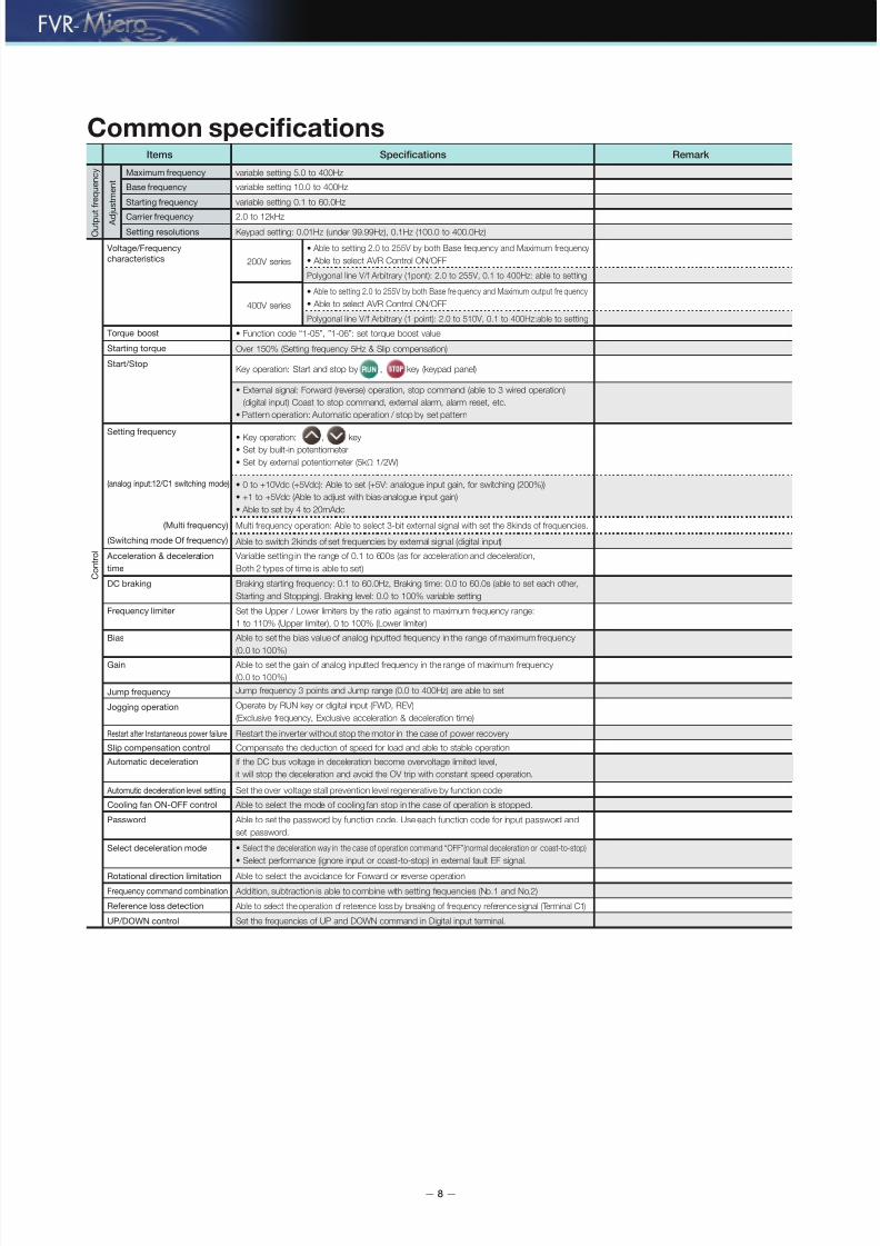
Common specifications
Maximum requency
Base requency
Starting requency
Carrier requency
Setting resolutions
Voltage/Frequency
characteristics
(Multi requency)
(Switching mode O requency)
(analog input:12/C1 switching mode)
Torque boost
Start/Stop
Setting requency
Acceleration & deceleration
time
Bias
Gain
Jump requency
Jogging operation
Restart ater Instantaneous power ailure
Slip compensation control
Automatic deceleration
Starting torque
Items Specifications Remark
variable setting 5.0 to 400Hz
variable setting 10.0 to 400Hz
variable setting 0.1 to 60.0Hz
2.0 to 12kHz
• Able to setting 2.0 to 255V by both Base frequency and Maximum frequency
• Able to select AVR Control ON/OFF
Polygonal line V/f Arbitrary (1pont): 2.0 to 255V, 0.1 to 400Hz: able to setting
• Function code “1-05”, ”1-06”: set torque boost value
Over 150% (Setting frequency 5Hz & Slip compensation)
Key operation: Start and stop by , key (keypad panel)
• External signal: Forward (reverse) operation, stop command (able to 3 wired operation)
(digital input) Coast to stop command, external alarm, alarm reset, etc.
• Pattern operation: Automatic operation / stop by set pattern
Able to switch 2kinds of set frequencies by external signal (digital input)
• Key operation: , key• Set by built-in potentiometer
• Set by external potentiometer (5kΩ 1/2W)
• 0 to +10Vdc (+5Vdc): Able to set (+5V: analogue input gain, for switching (200%))
• +1 to +5Vdc (Able to adjust with bias∙analogue input gain)
• Able to set by 4 to 20mAdc
Multi frequency operation: Able to select 3-bit external signal with set the 8kinds of frequencies.
Operate by RUN key or digital input (FWD, REV)
(Exclusive frequency, Exclusive acceleration & deceleration time)
Restart the inverter without stop the motor in the case of power recovery
Compensate the deduction of speed for load and able to stable operation
Jump frequency 3 points and Jump range (0.0 to 400Hz) are able to set
Able to set the gain of analog inputted frequency in the range of maximum frequency
(0.0 to 100%)
Able to set the bias value of analog inputted frequency in the range of maximum frequency
(0.0 to 100%)
Set the Upper / Lower limiters by the ratio against to maximum frequency range:
1 to 110% (Upper limiter), 0 to 100% (Lower limiter)
Variable setting in the range of 0.1 to 600s (as for acceleration and deceleration,
Both 2 types of time is able to set)
DC braking Braking starting frequency: 0.1 to 60.0Hz, Braking time: 0.0 to 60.0s (able to set each other,
Starting and Stopping). Braking level: 0.0 to 100% variable setting
Cooling an ON-OFF control Able to select the mode of cooling fan stop in the case of operation is stopped.
Automutic deceleration level setting Set the over voltage stall prevention level regenerative by function code
Password Able to set the password by function code. Use each function code for input password and
set password.
Select deceleration mode • Select the deceleration way in the case of operation command “OFF”(normal deceleration or coast-to-stop)
• Select performance (ignore input or coast-to-stop) in external fault EF signal.
Rotational direction limitation Able to select the avoidance for Forward or reverse operation
Frequency command combination Addition, subtraction is able to combine with setting frequencies (No.1 and No.2)
Reerence loss detection Able to select the operation of reterence loss by breaking of frequency reference signal (Terminal C1)
UP/DOWN control Set the frequencies of UP and DOWN command in Digital input terminal.
• Able to setting 2.0 to 255V by both Base fre quency and Maximum output fre quency
• Able to select AVR Control ON/OFF
Polygonal line V/f Arbitrary (1 point): 2.0 to 510V, 0.1 to 400Hz:able to setting
200V series
400V series
Keypad setting: 0.01Hz (under 99.99Hz), 0.1Hz (100.0 to 400.0Hz)
If the DC bus voltage in deceleration become overvoltage limited level,
it will stop the deceleration and avoid the OV trip with constant speed operation.
O u
t p u
t f r e q u e n c y
C o n
t r o l
A d
j u s
t m e n
t
Frequency limiter

7/27/2019 FVRMicro
http://slidepdf.com/reader/full/fvrmicro 9/24
— 9 —
Common specifications
S p
e c i f i c a t i o n s
I n d i c a
t i o n
P r o
t e c
t i o n
E n v
i r o n m e n
t
M
o t o r p r o t e c t i o n
Items Specifications Remark
Operating, Under Stop
Under Trip
Operating, Under Trip
Output frequency (before Slip compensation) [Hz] ∙ Output frequency (after Slip compensation) [Hz] ∙
Output current [A] ∙ Output voltage [V] ∙ DC bus voltage [V] ∙ Input power [kW], etc.
[Trip cause]
(overcurrent)(over voltage)
(overheating of heat sink)
(under voltage)
(overload of inverter “overheating of IGBT”)
(overload of motor 1)
(overload of motor 2), etc.
Trip history (last 6 times, indicate and storage)
Installation location
Ambient temperature
Ambient humidity
Altitude
Vibration
Storage temperature
Overload protection Protect inverter against overheating by overload of IGBT)
• Indoor, without corrosive gas, flammable gas and dust (pollution degree 2)
• Without direct sunlight
-10 to +50˚C
up to 90%RH (no dew condensation)
Under 1000m
9.80665m/s2 (1g): within up to 20Hz,
5.88m/s2 (0.6g): 20 to 50Hz
-20 to +60˚C
Overcurrent protection Stop inverter for overcurrent by overload of output side.
Overvoltage protection Stop inverter in case of detect the over DC bus voltage (200V: 400Vdc, 400V: 800Vdc)
Undervoltage protection Indicate the let down DC bus voltage (200V, 200Vdc, 400V: 400Vdc) and stop the inverter.
Electronic thermal Function of Electronic thermal makes stop the inverter and protect motor
(Thermal time constant: able to adjust 0.5 to 10.0 minute)
Short-circuit protection Stop inverter for overcurrent by short circuit of output side.
Auto-reset When it stops for trip, it is able to reset and restart automatically.
(Able to set the auto-reset times and the waiting time until the auto-reset)
Refer to the following section

7/27/2019 FVRMicro
http://slidepdf.com/reader/full/fvrmicro 10/24
— 10 —
Alarm indication and alarm release & troubleshooting method
1. Compare the motor current value with the inverter rated current,and check whether the inverter capacity is appropriate.
2. Check whether there is a short circuit on the inverter output
terminal (U, V, W).3. Check whether there is a short circuit on the motor connection or grounding.4. Check whether there is a loose wire connection between the
inverter and motor.5. Increase the acceleration time (1-09, 1-11).6. Check whether there is an overload on the motor.
An instantaneous value for the inverter output current exceeds theovercurrent level.
1. Check whether the input voltage exceeded the inverterspecification range, or whether there was a surge that entered theinput power supply.
2. Recalculate the deceleration torque from the load inertia momentand deceleration time, and increase the deceleration time.
The DC bus voltage exceeded the over voltage detection level.
1. Measure the ambient temperature.2. Check whether there is something obstructing or stuck to the heat
sink and whether the heat sink is operating properly.3. Check whether the inverter installation space is secure and free of
obstruction.
The internal temperature on the inverter rose abnormally.
1. Check whether the input voltage is correct.2. Check whether there are any sudden load increases.
The DC bus voltage dropped below the under voltage level.
1. Check whether there is an overload during operation.2. Increase the inverter capacity.
The output current exceeded the inverter’s overload capacity(150%/60 sec.).
1. Check whether there is an overload on the motor.2. Check the [7-00] motor’s total load capacity current setting.3. Check the electronic thermal function setting.4. Increase the motor capacity.
The electronic thermal function for motor overload detection wasactivated.
1. Check the motor’s output current.2. Check the over torque detection standard setting value (6-03).
Motor overload
Release the cause of the alarm, and push the “RESET” key.When the CM short circuits with the external multifunction input terminal,
used for the external alarm function (EF), the inverter stops output.
1. Turn the power supply OFF and turn it ON again.2. Make a repair request to the manufacturer.
Internal memory IC data writing error
1. Push the RESET key and restore the default setting.2. If this method is ineffective, send the product back to the
manufacturer for repair.Internal memory IC data reading error
1. Measure the ambient temperature.2. If the ambient temperature is normal, send the product back to the
manufacturer for repair.Internal temperature increase during startup.
1. Check whether the input voltage exceeded the inverter specification range.2. If the input voltage is normal, send the product back to the manufacturer
for repair. The DC bus voltage exceeded the over voltage level during startup.
1. Check whether the input voltage is correct.2. If the input voltage is normal, send the product back to the
manufacturer for repair.
The DC bus circuit voltage dropped below the under voltage levelduring startup.
Make a repair request to the manufacturer.Over voltage protection circuit error
Make a repair request to the manufacturer.Over current protection circuit error
If the input signal is cleared, “bb” will disappear.When inputting this function from the external multifunction terminal,the inverter stops output.
1. Check whether the communication circuit is connected correctly.2. Check whether the communications format is correct.
Communications error
Set the correct wobble frequency parameters. There is a wobble frequency setting error, the central frequency of wobblefrequency is below the amplitude setting, or the wobble frequency maximumvalue exceeds the upper and lower limit for the output frequency range.
Display code Description Alarm release & troubleshooting method

7/27/2019 FVRMicro
http://slidepdf.com/reader/full/fvrmicro 11/24
— 11 —
External dimensions
P r o t e c t i v e
f u n c t i o n s
E x t e r n a l
d i m e n s i o n s
1 8 0
. 0
1
5 1
. 6
72.0
148.059.0
Ø4.5
R2.25
1 6
. 4 5
FVR0.2 to 0.75S1S-7E/FVR0.4 to 1.5S1S-4E (Unit: mm)
1 8 0
. 0
1 6 2
. 9
100.0
148.089.0
Ø4.5
R2.25
1
0 . 8
FVR1.5 to 2.2S1S-7E/FVR2.2 to 3.7S1S-4E (Unit: mm)

7/27/2019 FVRMicro
http://slidepdf.com/reader/full/fvrmicro 12/24
— 12 —
How to operate
Each section name and function for the keypad
During operation or a stop:
Displays speed monitor (Output requency (Beoreslip compensation), output requency (Ater slipcompensation), setting requency, motor speed,load rotational speed, etc.), output current, outputvoltage, input power, etc.
Alarm mode:
Displays the alarm description with a code.
Switches between modes.
Normal mode:
You can switch on the LED monitor. Alarm mode:
Releases the trip stoppage.
Used to display and check the unctioncode and data.
During operation: Used to increase and decrease therequency and speed.
When setting: Changes the unction code display andthe data setting value.
LED monitor
Mode key / Reset key
Function key input
Up / Down keys
This key starts the running operation.
While stopped:
When the unction code is set to
something besides “ ” (keypad
operation), it will not operate.
Operation key
This key stops the running operation.
While operating:
Operation is not enabled when the unction
code is set to “ ” (Running
rom an external signal (Keypad stop key
disabled)) or “ ” (Running via
RS-485 communications (Keypad stop keydisabled)).
Stop key
Used or requency setting.
Potentiometer
Display and key operations The keypad modes are divided into the following 3 modes.
Display section& operation section
D i s p l a y
s e c t i o n
O p e r a t i o n s e c t i o n
Programming mode
Stopped Operating
Running mode
Stopped Operating Alarm mode
Operationmodes
Function
Display
Display unction code and data
Display output requency, setting requency,
load rotation speed, input power, output current,
output voltage, etc.
Display alarm
description
Function
Function
Function
Function
Function
Change to stop modeChange
to operation mode
Release trip and
change to stop mode
or operation mode
Change
to program mode(while operating)
Change to operation mode(while operating) Disabled DisabledDisabled
Disabled Disabled Disabled
Change
to program mode
(while stopped)
Change mode
to program mode
(while stopped)
Change mode
to program mode
(while operating)
Change to operation mode
(while stopped)
Increase/decrease unction code and data Increase/decrease setting, such as requency setting Disabled
Select and set unction code,
and record & update data
Switch to display contents on LED monitor
Disabled
Light on Light on Light on

7/27/2019 FVRMicro
http://slidepdf.com/reader/full/fvrmicro 13/24
— 13 —
Terminal Functions
H o w t o
o p e r a t e
T e r m i n a l
f u n c t i o n s
M a i n C i r
c u i t
F r e q u e n c y S e t t i n g
D i g i t a l i n p u t
L1/R, L2/S, L3/T
L1/L, L2/N
U, V, W
(+), (-)
G
Main power supply
Inverter output
Brake unit connection use
Inverter earth connection use
Connect to the 3-Phase power supply.
Connect to the single phase power supply.
Connect to 3-phase motor.
Connect with braking unit (option).
Inverter earth connection terminal.
13
11
12/C1
Change-over
by switch
Potentiometer power supply
Analog common
Frequency setting voltage input
Use requency setting (potentiometer: 5kΩ) as power supply. (10Vdc 3mAdc max.)
0 to +10Vdc/0 to 100% (0 to +5Vdc/0 to 100%)
Common terminal or analog input / output signals (12, 13, C1, FMA).
Input impedance: 47kΩ
Frequency setting current Input 4 to 20mAdc/0 to 100% Input impedance: 250Ω
Isolate to CM terminal .
Setting is only available to FWD, REV
terminals
FWD
REV
X1
X2
X3
FWD operation command • The unctions below can be set on terminal X1-X3, FWD and REV.
<Common Function>
• Sink/Source can be switched by the jumper switch built-in the inverter
REV operation command
Digital input 1
Digital input 2
Digital input 3
No Function No aect to behavior both ON/OFF
Symbol Terminal name Specifications Remark
FWD, REV terminal can also be used
or other unctions.
Switch SINK/SOURCE by switch.
(NONE)FWD operation command When (FWD) is ON, orward operation, when OFF, it will stop ater deceleration(FWD)
REV operation command When (REV) is ON, reverse operation, when O, it will stop ater deceleration(REV)
Run/stop command When (CRUN) is ON, it runs, when OFF it will stop ater deceleration.(CRUN)
FWD/REV command When (CRUN) is ON, and (FWD/REV) is ON, orward operation, when
(FWD/REV) is OFF, reverse operation
(FWD/REV)
3-wire operation/
stop command(HLD) • Used as sel hold signal in 3-wire operation case.
• When (HLD) is ON, (FWD) or (REV) signal will be sel held and it will be released when the signal is OFF
• The inverter output is shut o immediately and the motor
coasts-to-stop when (EF1) is ON.
PLC PLC signal power supply
CM Digital input common
The alarm hold will be released when (RST) is ON.
8 step speed running is possible by the ON/OFF signal rom (SS1) to (SS4).
Frequency setting2 /frequency setting1 When (Hz2/Hz1) is ON, requency setting 2 will be selected.(Hz2/Hz1)
EF,
Normal Open input
• The inverter output is shut o immediately and the motor coasts-to-stop
when (EF2) is OFF.
(EF1)
EF,
Normal close input
(EF2)
Multi frequency
selection
(SS1)
(SS2)
(SS4)
Alarm reset(RST)
When (HLR-HLD)is ON the acceleration and deceleration will prohibited. Acceleration prohibition command(HLR-HLD)
Selection o acceleration/deceleration time 2/1 is possible by the ON/OFF o (RT1). Acceleration time selection(RT1)
Output o inverter shall stop immediately by (B.B) ON.External alarm,
normal open input
(BB1)
Output o inverter shall stop immediately by (B.B) OFF.External alarm,
normal close input
(BB2)
Frequency up command will be done by (UP) ON.UP Command(UP)
Frequency down command will be done by (DOWN) ONDOWN Command(DOWN)
Pattern operation can be started by (AUTO) ON.Pattern operation command(AUTO)
Pattern operation can be paused by (PAUSE) ON.Pattern operation interruption command(PAUSE)
Select jogging requency by (JOG-) ON.Jogging frequency command(JOG-f)
Reset current count by (CNT-RST) ON.Counter reset(CNT-RST)
Select input rom terminal C1 by (SEL-C1) ON.C1 terminal selection(SEL-C1)
Jogging FWD by (JOG-FWD) ON.Jogging FWD command(JOG-FWD)Jogging REV by (JOG-REV) ON.Jogging REV (JOG-REV)
Start wobble requency operation by (WFI) ON.Wobble frequency input(WFI)
Start wobble requency operation by (WFI-RST) ON.Wobble frequency input reset(WFI-RST)
Emergency stop by (EN1) ON.Emergency stop 1
normal open input
(EN1)
Emergency stop by (EN2) OFF.Emergency stop 2
normal close input
(EN2)
Counter trigger signal(CNT)
Connect with the PLC output signal power supply. Also available as 24V power supply. +24V Max. 20mA
Common terminal o digital input signal Isolate rom terminal 11
Counter signal is input to (CNT)
S o r t

7/27/2019 FVRMicro
http://slidepdf.com/reader/full/fvrmicro 14/24
— 14 —
Terminal Functions
A n a l o g o u t p u t
S o r t
T r a n s i s t o r o u t p u t / R e l a y o u t p u
t
c o m m u n i c a t i o n s
Symbol Terminal name Specifications Remark
Isolate rom terminal 11
FMA Analog monitor One item selected rom items below can be output by DC voltage.
• output requency 1 (beore slip compensation)
• output requency 2 (ater slip compensation)
• output current
• output voltage
• DC bus voltage
• Input power
*analog voltmeter (0 to 10Vdc, Max 3mA input impedance: 3.3kΩ) can be used.
Gain adjustment range:1 to 200%
Y1
30A, 30B, 30C
Transistor output
Alarm output
(for any alarm)
(Relay output)
• Output the selected signal rom below. (48Vdc, Max. 50mAdc)
CM Transistor output common Emitter terminal or transistor output signal (Y1)
ON signal will be output when inverter runs over starting requency.
When inverter stops during alarm, the voltage-less point signal (1c) will be output.
• The ollowing signal is selectable as multi-purpose relay output
(contact rating: 240Vac, 1.5Aac (Normal open)/0.5Aac(Normal close))
• The alarm output is switchable by excitation or non-excitation.
(NON) No function
(RUN) Inverter running
ON signal will be output when output requency reaches the setting requency.
Detecting range is(ON: 1.0Hz, OFF: 3.0Hz)fxed.
(FAR) Frequency arrival
ON signal will be output during stop.(ZERO) Zero speed
ON signal will be output by over torque detection.(OT) Over torque detection
ON signal will be output during outside base block by base block signal.(BB) During external alarm
ON signal will be output by under voltage.(LU) Low voltage detection
ON signal will be output under running mode rom external terminal.(REM) External terminal running mode
Batch alarm signals can be output as transistor output signal.(ALM) Alarm output (for any alarm)
ON signal will be output when the output requency is over the setting detection level.(FDT) Frequency detection
ON signal output during pattern operation(AUTO) During pattern operation
ON signal will be output ater 1 cycle pattern operation completes.(TO) Pattern operation one cycle completion
ON signal will be output when pattern operation completes.(TE) Pattern operation completion
ON signal will be output during pattern operation pause.(TP) Pattern operation pause
ON signal output on terminal value arrival.(CAR) Terminal count value arrival
ON signal output on terminal designated count value arrival(CARF) Terminal designated count value arrival
ON signal will be output when inverter running preparation is fnished.(RDY) Inverter ready to run
ON signal output during FWD operation.(FRUN) Fwd running
ON signal output during REV operation.(RRUN) Rev running
OFF during FWD operation, ON during REV operation.(FRRUN) Fwd/Rev running direction
RS-485
Communications connector
(RJ-45 connector)
RS-485
communications
Input/output
Modbus-RTU protocol is built in the inverter

7/27/2019 FVRMicro
http://slidepdf.com/reader/full/fvrmicro 15/24
— 15 —
Terminal configuration diagram
Basic connection diagram
■Main circuit terminals ■Control circuit terminals
3-phase 400V Single-phase 200V
Input side
Output side
[13]
[12/C1]
[11]
[FMA]
(+) (-)
L1/R
50Hz/60Hz
L2/S
L3/T
MCCB or ELCB (*2)
50Hz/60Hz
L1/L
L2/N
Earth terminal G Earth terminal
Motor
G
M3~
U
V
W
30A
30B30
3
2
1
30C
Power supply orvariable resistor
<Y1>
<CM>(X2)
(X1)
(X3)
(CM)
(FWD)
(PLC)
(REV)
(CM)
Instead o variable resistor,
the voltage signal input to
terminal [12/C1]- [11] (0 to
+10Vdc or 0 to +5Vdc) is
possible Or input rom 4 to
20mAdc is possible by
switching shit
*1) Use the power supply suiting
to the inverter rated voltage.
*2) Peripheral device. Use it
when necessary
*3) The correspondence is
undecided.
Shiting between
SINK/SOURCE by
swtich is possible.
Analog meter
(*2)
Voltage inputor setting use
0~10VdcOR
current inputor setting use4 to20mAdc
A n a
l o g
i n p u
t
Digital input
380~460V
Power supply (*1)3-phase
Power supply (*1)
Single phase
MCCB or ELCB (*2)
200~240V
Brake unit+brake resistor (*3)
Alarm output (or any alarm)
Transistor output
PLC
30A 30B 30C REV X2 Y1 CM FMA 11
FWD X1 X3 13 12/C1
RS-485 port
T e r m i n a l
f u n c t i o n s
T e r m i n a l
c o n f i g u r a
t i o n
d i a g r a m
C o n n e c t i o n
d i a g r a m
7/27/2019 FVRMicro
http://slidepdf.com/reader/full/fvrmicro 16/24
— 16 —
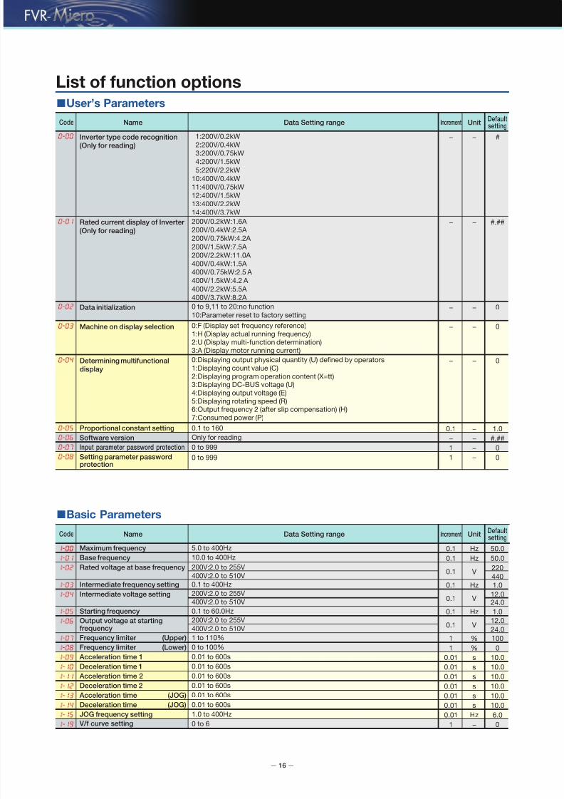
List of function options■User’s Parameters
■Basic Parameters
0:Displaying output physical quantity (U) defned by operators1:Displaying count value (C)2:Displaying program operation content (X=tt)3:Displaying DC-BUS voltage (U)4:Displaying output voltage (E)5:Displaying rotating speed (R)6:Output requency 2 (ater slip compensation) (H)
7:Consumed power (P)
Determining multifunctional
display
0− −
0:F (Display set requency reerence)1:H (Display actual running requency)2:U (Display multi-unction determination)3:A (Display motor running current)
Machine on display selection 0− −
Code Name Data Setting rangeDefaultsetting
Increment Unit
200V/0.2kW:1.6A
200V/0.4kW:2.5A
200V/0.75kW:4.2A
200V/1.5kW:7.5A
200V/2.2kW:11.0A
400V/0.4kW:1.5A
400V/0.75kW:2.5 A
400V/1.5kW:4.2 A 400V/2.2kW:5.5A
400V/3.7kW:8.2A
Rated current display of Inverter
(Only for reading)
#.##− −
1:200V/0.2kW2:200V/0.4kW
3:200V/0.75kW
4:200V/1.5kW
5:220V/2.2kW
10:400V/0.4kW
11:400V/0.75kW
12:400V/1.5kW
13:400V/2.2kW
14:400V/3.7kW
0 to 9,11 to 20:no unction
10:Parameter reset to actory settingData initialization 0− −
− − #Inverter type code recognition(Only for reading)
0 to 999Input parameter password protection 01 −
0.1 to 160
Only or reading
Proportional constant setting 1.00.1 −
Software version #.##− −
0 to 999Setting parameter passwordprotection
01 −
Code Name Data Setting rangeDefaultsetting
Increment Unit
5.0 to 400Hz
10.0 to 400Hz
Maximum frequency 50.00.1 Hz
Base frequency 50.00.1 Hz200V:2.0 to 255V
400V:2.0 to 510V
Rated voltage at base frequency 220
4400.1 V
0.1 to 400HzIntermediate frequency setting 1.00.1 Hz200V:2.0 to 255V
400V:2.0 to 510VIntermediate voltage setting 12.0
24.00.1 V
0.1 to 60.0HzStarting frequency 1.00.1 Hz
200V:2.0 to 255V
400V:2.0 to 510VOutput voltage at startingfrequency
12.0
24.00.1 V
Frequency limiter (Upper) 1001 %
Frequency limiter (Lower) 01 %
Acceleration time 1 10.00.01 s
Deceleration time 1 10.00.01 s
Acceleration time 2 10.00.01 s
Deceleration time 2 10.00.01 s
Acceleration time (JOG) 10.00.01 sDeceleration time (JOG) 10.00.01 s
JOG frequency setting 6.00.01 Hz
V/f curve setting 01 −
1 to 110%
0 to 100%
0.01 to 600s
0.01 to 600s
0.01 to 600s
0.01 to 600s
0.01 to 600s0.01 to 600s
1.0 to 400Hz
0 to 6

7/27/2019 FVRMicro
http://slidepdf.com/reader/full/fvrmicro 17/24
— 17 —
■Operation Mode Parameters
Notes:
1) In 2-00 and 2-01, when 2-00 has been set as d1 (12) or d2 (C1), 2-01 can’t be set as d1 or d2 again.
2) In 2-00 and 2-01, when 2-00 has been set as d6 or d7 (controlled by UP/DOWN), 2-01 can’t be set as d6 or d7 again.
3) The parameter o 2-07 is valid only when the requency is given by analog input 12 and input set 0. I the requency is given by 12,
but press the STOP key, the inverter will stop still according to the mode o 2-04.
F u
n c t i o n
o
p t i o n s
<Changing, validating and saving data during operation>: Not possible :Ater changing with the keys, validate or save the data with “ ” key.
Code Name Data Setting rangeDefaultsetting
UnitIncrement
0:Keys on keypad1:Input DC 0 to 10V by external terminals 12
2:Input DC 4 to 20mA by external terminals C1
3:Controlled by VR on keypad
4:Operated by RS-485 communications interace
5:Operated by RS-485 communications interace (Frequency memory)
6:Controlled by UP/DOWN
7:Controlled by UP/DOWN (Frequency memory)
Frequency command 1 3− −
0: Keys on keypad
1:Input DC 0 to 10V by external terminals 12
2:Input 4 to 20mA by external terminals C1
3:Controlled by VR on keypad panel
6:Controlled by UP/DOWN
7:Controlled by UP/DOWN (Frequency memory)
Frequency command 2 0− −
0:Frequency command 1
1:Frequency command 1 + Frequency command 2
2:Frequency command 1 - Frequency command 2
Combination way of frequency
sources
0− −
0:Operated by keypad1:Operated by external terminals. STOP on keypad available2:Operated by external terminals. STOP on keypad unavailable3:Operated by communications Interace RS-485. STOP on keypad available4:Operated by communications Interace RS-485. STOP on keypad unavailable
Operation method 0− −
0:Normal deceleration
1:Coast to stopDeceleration mode
External fault (EF) stop mode
0− −
0:Deceleration stop
1:Coast to stop
2:Holding operation command ater deceleration stop
Reference loss detection
(Terminal 12) (Stop mode)
2− −
2.0 to 12.0kHzMotor sound (Carrier frequency) 6.00.1 kHz
0:Fwd/Rev run available
1:Rev run inhibited
2:Fwd run inhibited
Rotation direction limitation 0− −
0:Non-processing1:Coast to stop
2:EF display ater deceleration stop
3:Continuous operation by reerence requency beore disconnection
Reference loss detection(Terminal C1) (Stop mode)
0− −
0:Operation available
1:Operation unavailablePower on start 0− −
1:External ault (EF) coast to stop 1− −

7/27/2019 FVRMicro
http://slidepdf.com/reader/full/fvrmicro 18/24
— 18 —
List of function options■Output Function Parameters
1.0 to 400Hz0 to 999
0 to 999
0.0 to 60.0s
0.0 to 60.0s
Frequency detection (Level)
Rev run reference delay setting
0:No unction
1:Inverter running
2:Frequency arrival
3:Zero speed
4:Over-torque detection
5:During external alarm
6:Low voltage detection
7:External terminal running mode
8:Alarm output (or any alarm)
9:Frequency detection
10:During pattern operation
11:Pattern operation one cycle completion12:Pattern operation completion
13:Pattern operation pause
14:Terminal count value arrival
15:Terminal designated count value arrival
16:Inverter ready to run
17:Fwd running
18:Rev running
19:Fwd/Rev running direction
Terminal [30A/B/C] function
(Relay output)
Normally open contactor
(30A-30C)
Normally closed contactor
(30B-30C)
Count value agreement setting
Appointed count agreement setting
Fwd run reference delay setting
0.0 to 10.0V
0.0 to 100% o Maximum requency
0.0 to 10.0V
0.0 to 100% o Maximum requency
0.0 to 20.0mA
0.0 to 100% o Maximum requency
0.0 to 20.0mA
0.0 to 100% o Maximum requency
Bias [12] (Bias base point)
(Bias value)
Analog input adjustment for [12]
(Gain base point)
(Gain)
Bias [C1] (Bias base point)
(Bias value)
Analog input adjustment for [C1](Gain base point)
(Gain)
0.0 to 600 s
0:Fan continuous running
1:Run or 1 minute ater pressing stop key
2:Operate/stop along with inverter
Cooling fan control
Dead time setting of Fwd andRev changeover
0:No unction1:Inverter running
2:Frequency arrival
3:Zero speed
4:Over-torque detection
5:During external alarm
6:Low voltage detection
7:External terminal running mode
8:Alarm output (or any alarm)
9:Frequency detection
10:During pattern operation
11:Pattern operation one cycle completion
12:Pattern operation completion
13:Pattern operation pause
14:Terminal count value arrival
15:Terminal designated count value arrival
16:Inverter ready to run
17:Fwd running
18:Rev running
19:Fwd/Rev running direction
Analog output gain selection
Terminal [Y1] function
0:Output requency 1 (beore slip compensation)
1:Output requency 2 (ater slip compensation)
2:Analog current meter (0 to 250% o rated current)
3:Analog output voltage
4:Analog DC bus voltage
5:Input power
1 to 200%
Analog output setting
1.00.1 Hz
0.00.1 s
8− −
01 −
01 −
0.00.1 s
1001 %
0.00.1 V
0.00.1 %
10.00.1 V
1000.1 %
4.00.1 mA
0.00.1 %
20.00.1 mA
1000.1 %
0− −
0.00.1 s
1− −
0− −
Code Name Data Setting rangeDefaultsetting
Increment Unit

7/27/2019 FVRMicro
http://slidepdf.com/reader/full/fvrmicro 19/24
— 19 —
■Input Function Parameters
■Multi-Step Speed and Pattern Operation Parameters
Notes: When 4-04 is set as d1 to d2, unction set by REV is invalid. When 4-04 is set as d3 to d4, unction set by REV and X1 is invalid.
F u
n c t i o n
o
p t i o n s
<Changing, validating and saving data during operation>
: Not possible :Ater changing with the keys, validate or save the data with “ ” key.
[VR] Input frequency bias setting[VR] Input frequency biasadjustment direction
0.0 to 350Hz
0:No unction
1:FWD: orward run/stop, REV: reverse run/stop
2:FWD: run/stop, REV: wd/rev run
3:3-wire operation control (1): FWD run, REV wd/rev run, X1 STOP (Normally closed)
4:3-wire operation control (2): FWD run (Triggering), REV run (Triggering), X1 STOP (Normally closed)5:External ault (EF), normally open interace input (N.O)
6:External ault (EF) normally closed interace input (N.C)
7:RESET alarm8:Select multi-requency (0 to 1 steps)
9:Select multi-requency (0 to 3 steps)
10:Select multi-requency (0 to 7 steps)
12:Select requency command 2/1
13:Accel/Decel inhibition command
14:Select 1ST and 2nd Accel/Decel time
15:External alarm, normally open (NO) input
16:External alarm, normally closed (NC) input
17:Up command
18:Down command
19:Pattern operation command
20:Pattern operation pause command
21:JOG requency reerence
22:Count reset
24:JOG-FWD
25:JOG-REV27:Wobble requency unction input
28:Wobble requency state reset
29:Inhibiting output (N.O)
30:Inhibiting output (N.C)
31:Counter trigger signal input
[VR] Negative bias operationsetting
Terminal [FWD] function(Setting range from d0 to d31)*
Terminal [REV] function(Setting range d0, d5 to d31)
Terminal [X1] function(Setting range d0, d5 to d31)
Terminal [X2] function(Setting range d0, d5 to d31)
Terminal [X3] function(Setting range d0, d5 to d31)
Speed tracking after externalalarm reset
0:No negative bias
1:Reversible negative bias
2:Not reversible negative bias
0:Tracking downwards rom speed beore external alarm
1:Tracking upwards rom min speed
[VR] Input frequency gain setting 1 to 200%
0:Positive direction
1:Negative direction
0.00.1 Hz
0− −
1−
0− −
−
1001 %
0− −
0− −
8− −
9− −
7− −
0.0 to 400Hz
0.0 to 400Hz
0.0 to 400Hz0.0 to 400Hz
0.0 to 400Hz
0.0 to 400Hz
0.0 to 400Hz
0:Pattern operation inactive
1:Active (Stop ater operating or 1 cycle)
2:Active (Pattern operation perorms in cycles until STOP command input)
3:Active (Stop ater operating or 1 cycle) (with STOP intervals).
4: Active (Pattern operation perorms in cycles until STOP command input) (with STOP intervals).
Multi frequency 1
2
34
5
6
7
0.00.1 Hz
0.00.1 Hz
0.00.1 Hz0.00.1 Hz
0.00.1 Hz
0.00.1 Hz
0.00.1 Hz
Pattern operation (Mode) − −
01 −(Rotating drection)
(Step 0 time)
(Step 1 time)
(Step 2 time)
(Step 3 time)
(Step 4 time)
(Step 5 time)
(Step 6 time)
(Step 7 time)
0 to 65500s
0 to 65500s
0 to 65500s
0 to 65500s
0 to 65500s
0 to 65500s
0 to 65500s
0 to 65500s
0 to 255 (0: Forward Run 1: Reverse Run)
01 s
01 s
01 s
01 s
01 s
01 s
01 s
01 s
0
Code Name Data Setting rangeDefaultsetting
Increment Unit
Code Name Data Setting rangeDefaultsetting
Increment Unit

7/27/2019 FVRMicro
http://slidepdf.com/reader/full/fvrmicro 20/24
— 20 —
List of function options
■Motor Parameters
■Protection Parameters
■High Function Parameters
Code Name Data Setting rangeDefaultsetting
Increment Unit
Code Name Data Setting rangeDefaultsetting
Increment Unit
Code Name Data Setting rangeDefaultsetting
Increment Unit
0:Inactive200V series:340-400V400V series:680-800V0:No detection1:Over torque detection (0L2) during constant speed running, continue to run ater detection.2:Over torque detection (0L2) during constant speed running, stop running ater detection.3:Over torque detection (0L2) during acceleration, continue to run ater detection.4:Over torque detection (0L2) during acceleration, stop running ater detection.
0.1 to 10.0s
30 to 200%
Over voltage stall preventionfunction − −370
740
Over-torque detection(Mode selection)
0− −
0.10.1 s
601 s(Thermal time constant)
Alarm history (Latest)
(1st last)
(2nd
last)(3rd last)
(4th last)
(5th last)
0− −
0− −0− −
0− −
0− −
1501 %(Detection level)
(Detection time)
Electronic thermal overloadprotection for Motor (Select motor characteristics)
0− −0:Inactive
1:Active (For a general-purpose motor with shat-driven cooling an)
2:Active (For a motor with separately powered cooling an)
30 to 600s
0− −
0:No alarm records
1:OC (Over current)
2:OV (Over voltage)3:OH (Over heating o heat sink)
4:OL (Overload o inverter “overheating o IGBT”)
5:OL1 (Motor overload) (Overload o motor 1)
6:EF (External ault)
16:CF2 (Read error o internal storage IC data)
17:External alarm signal input
18:OL2 (Overload o motor 2)
22:CF3.1 (Internal temperature is over high or circuit ault at power-on test)
23:CF3.2 (Over voltage o internal DC voltage side at power-on test)
24:CF3.3 (Under voltage o internal DC voltage side at power-on test )
29:HPF.1 (Over voltage protection circuit ault)
31:HPF.3 (Over current protection circuit ault)
37:Errb (Wobble requency setting error)
301 %
Auto slip compensation setting 0.00.1 −
Motor (Rated speed)
(Pole number)
(Rated frequency)
14501 min-1
42 Poles
Motor (Rated current)
(No load current)
851 %
50.00.1 Hz
30 to 120%
0 to 90%
0.0 to 10.0
500 to 3000min-1
0 to 30pole
5.0 to 400Hz
0.00.1 s
0.00.1 s
1.00.1 Hz
0.50.1 s
Jump frequency 1 (Upper)
(Lower)
Jump frequency 2 (Upper)
(Lower)
Jump frequency 3 (Upper)
(Lower)
0.00.1 Hz
1501 %
0.00.1 Hz
0.00.1 Hz
0.00.1 Hz
Auto-reset (Counter clear time)
Auto-reset (Reset interval)
101 min
2.00.1 s
0.00.1 Hz
0.00.1 Hz Auto-reset (Times) 01 −
0.0 to 100%0.0 to 60.0s
0.0 to 60.0s
0.1 to 60.0Hz
DC braking (Braking level)(Braking time at starting)
(Braking time at stopping)
(Braking starting frequency)
0.00.1 %
0:Inactive (Trip immediately)
1: Active (Restart at the requency at which the power ailure occurred, or general loads)
2:Active (Restart at the starting requency, or light inertia loads)
Restart after momentary power failure
(Mode selection)
(Max allowable time for power failure)
(Restart time)
(Max current setting for speed tracking)
0− −
0.3 to 5.0s
0.3 to 5.0s
30 to 200%
0.0 to 400Hz
0.0 to 400Hz
0.0 to 400Hz
0.0 to 400Hz
0.0 to 400Hz
0.0 to 400Hz0 to 10
2.00.1 s
0:AVR unction available
1:AVR unction unavailable
2:AVR unction cancelled during deceleration
AVR function selection 1− −
1 to 100 min
0.1 to 20.0s

7/27/2019 FVRMicro
http://slidepdf.com/reader/full/fvrmicro 21/24
— 21 —
■Communication Parameters
■Wobble Frequency Function Parameters
F u
n c t i o n
o
p t i o n s
<Changing, validating and saving data during operation>
: Not possible :Ater changing with the keys, validate or save the data with “ ” key.
Code Name Data Setting rangeDefaultsetting
Increment Unit
Code Name Data Setting rangeDefaultsetting
Increment Unit
1 to 2470:Baud rate 4800 bps
1:Baud rate 9600
2:Baud rate 14400
3:Baud rate 19200
4:Baud rate 38400
RS-485 Communications (Station address) 11 −1− −(Baud rate)
0− −(Communications error processing) 0:Warning and running continuously
1:Warning and deceleration to stop
2:Warning and coasting to a stop
3:No warning and running continuously
01 s(No-response error detection time) 0:Not detected
1 to 20s
0− −(Communications format)
<Data length, Parity, STOP bit>
0:ASCII mode <8, N,1>
1:ASCII mode <8, N,2>
2:ASCII mode <8, E,1>
3:ASCII mode <8, E,2>
4:ASCII mode <8, O,1>5:ASCII mode <8, O,2>
6:RTU mode <8, N,2>
7:RTU mode <8, E,1>
8:RTU mode <8, O,1>
0 to 200 (one unit=2ms) 11 −(Response interval)
0:Not applying
1:ApplyingWobble frequency selection 0− −
0:Set according to wobble requency action delay
1:Controlled by external terminals.Wobble frequency input mode 0− −
0.0 to 400Hz0.0 to 600s
Pre-set frequency of wobble Frequency 0.00.1 Hz Action delay setting of preset wobble frequency 0.00.1 s
0:According to operation requency source
1:According to fxed requency setting (A-05)
Central frequency of wobblefrequency
0− −
0.01 to 100%Fixed central frequency setting of wobblefrequency (Max frequency base)
20.00.1 %
0:Centering requency base
1:Max requency (1-00) base
Reference source settingfor wobble aptitude
0− −
0.0 to 50.0%
0.0 to 50.0%
0.1 to 655s
0.1 to 99.9%
Wobble aptitude width setting 0.00.1 %
Wobble frequency hopping (Relative aptitude) 0.00.1 %
Wobble frequency cycle 10.00.1 s
Triangle wave rising time (Relative cycle) 50.00.1 %
0:Starting in memorizing state beore stop
1:Restarting
Wobble frequency machinestop starting mode
0− −
0:Memorizing
1:Non-memorizing
Wobble state power loss memory 0− −
7/27/2019 FVRMicro
http://slidepdf.com/reader/full/fvrmicro 22/24
— 22 —
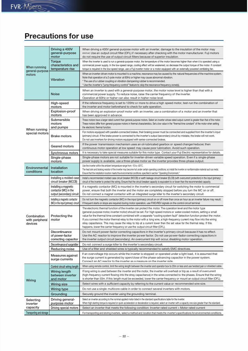
Precautions for use
When runnninggeneral-purposemotors
When runningspecial motors
Environmentalconditions
Driving a 400V general-purposemotor
When driving a 400V general-purpose motor with an inverter, damage to the insulation o the motor may
occur. Use an output circuit flter (OFL) i necessary ater checking with the motor manuacturer. Fuji motors
do not require the use o output circuit flters because o superior insulation.
Torquecharacteristics andtemperature rise
When the inverter is used to run a general-purpose motor, the temperature o the motor becomes higher than when it is operated using acommercial power supply. In the low-speed range, cooling eect will be weakened, so decrease the output torque o the motor. I constant
torque is required in the low-speed range, use a Fuji inverter motor or a motor equipped with an externally powered ventilating an.
Vibration
When an inverter-driven motor is mounted to a machine, resonance may be caused by the natural requencies o the machine system.
Note that operation o a 2-pole motor at 60Hz or higher may cause abnormal vibration.
* The use o a rubber coupling or vibration dampening rubber is recommended.
* Use the inverter's ”jump requency control” eature to skip the resonance requency zone(s).
NoiseWhen an inverter is used with a general-purpose motor, the motor noise level is higher than that with a
commercial power supply. To reduce noise, raise the carrier requency o the inverter.
Operation at 60Hz or higher can also result in higher noise level.
Explosion-proofmotors
When driving an explosion-proo motor with an inverter, use a combination o a motor and an inverter that
has been approved in advance.
High-speedmotors
I the reerence requency is set to 120Hz or more to drive a high speed motor, test-run the combination o
the inverter and motor beorehand to check or sae operation.
Submersible
motorsand pumps
These motors have a larger rated current than general-purpose motors. Select an inverter whose rated output current is greater than that o the motor.
These motors dier rom general-purpose motors in thermal characteristics. Set a low value in the “thermal time constant” o the motor when setting
the electronic thermal unction.
Brake motors
For motors equipped with parallel-connected brakes, their braking power must be connected and supplied rom the inverter’s input
(primary) circuit. I the brake power is connected to the inverter's output (secondary) circuit by mistake, the brake will not work.
Do not use inverters or driving motors equipped with series-connected brakes.
Geared motors
Synchronous motors It is necessary to take special measures suitable or this motor type. Contact your Fuji Electric representative or details.
Single-phasemotors
Single-phase motors are not suitable or inverter-driven variable speed operation. Even i a single-phase
power supply is available, use a three-phase motor as the inverter provides three-phase output.
Installationlocation
Use the inverter within the ambient temperature range rom -10 to +50°C.
The heat sink and braking resistor o the inverter may become hot under certain operating conditions, so install the inverter on nonammable material such as metal.
Ensure that the installation location meets the environmental conditions specifed in section "Operating Environment."
Installing a molded casecircuit breaker (MCCB)
Install a recommended molded case circuit breaker (MCCB) or earth leakage circuit breaker (ELCB) (with overcurrent protection) in the input (primary)
circuit o the inverter to protect the wiring. Ensure that the circuit breaker capacity is equivalent to or lower than the recommended capacity.
Installing a magneticcontactor (MC) in theoutput (secondary) circuit
I a magnetic contactor (MC) is mounted in the inverter's secondary circuit or switching the motor to commercial
power, ensure that both the inverter and the motor are completely stopped beore you turn the MC on or o.
Do not connect a magnet contactor with an integrated surge killer to the inverter's secondary circuit.
Combinationwith peripheraldevices
Selectinginverter
capacity
Transporting and storage
Wiring
Installing a magnetic contactor (MC) in the input (primary) circuit
Do not turn the magnetic contactor (MC) in the input (primary) circuit on or o more than once an hour as an inverter ailure may result.
I requent starts or stops are required during motor operation, use FWD/REV signals on the control circuit terminal.
Protecting themotor
Discontinuance of surge killer
The electronic thermal unction o the inverter can protect the motor. The operation level and the motor type
(general-purpose motor, inverter motor) should be set. For high speed motors or water-cooled motors, setting a small
value or the thermal time constant combined with a separate “cooling system ault” detection unction protect the motor.
I you connect the motor thermal relay to the motor with a long wire, a high-requency current may ow into the wiring
stray capacitance. This may cause the relay to trip at a current lower than the set value or the thermal relay. I this
happens, lower the carrier requency or use the output circuit flter (OFL).
Discontinuanceof power-factor correcting capacitor
Do not connect a surge killer to the inverter's secondary circuit.Reducing noise Use o a flter and shielded wires is typically recommended to satisy EMC directives.
Measures againstsurge currents
I an overvoltage trip occurs while the inverter is stopped or operated under a light load, it is assumed that
the surge current is generated by open/close o the phase-advancing capacitor in the power system.
Connect an AC reactor to the inverter as a measure on the inverter side.
Driving general-purpose motor
Select an inverter according to the nominal applied motor listed in the standard specifcations table or the inverter.
When high starting torque is required or quick acceleration or deceleration is required, select an inverter with a capacity one size greater than the standard.
Control circuit wiring length When using remote control, limit the wiring length between the inverter and operator box to 20m or less and use twisted pair o r shielded cable.
Wiring size Select wires with a sufcient capacity by reerring to the current value or recommended wire size.
Wiring type Do not use a single multicore cable in order to connect several inverters with motors.
Grounding Securely ground the inverter using the grounding terminal.
Driving special motors Select an inverter that meets the ollowing condition: Inverter rated current > Motor rated current
For transporting and storing inverters, select a method and location that meets the inverter’s specifcations or environmental conditions.
Wiring lengthbetween inverter and motor
I long wiring is used between the inverter and the motor, the inverter will overheat or trip as a result o overcurrent
(high-requency current owing into the stray capacitance) in the wires connected to the phases. Ensure that the wiring
is shorter than 50m. I this length must be exceeded, lower the carrier requency or mount an output circuit flter (OFL).
I the power transmission mechanism uses an oil-lubricated gearbox or speed changer/reducer, then
continuous motor operation at low speed may cause poor lubrication. Avoid such operation.
Do not mount power-actor correcting capacitors in the inverter’s primary circuit because it has no eect.
Use the AC reactor to improve the inverter power actor. Do not use power-actor correcting capacitors in
the inverter output circuit (secondary). An overcurrent trip will occur, disabling motor operation.

7/27/2019 FVRMicro
http://slidepdf.com/reader/full/fvrmicro 23/24
— 23 —
MEMO
P r e c a u t i o n s
f o r u s e

7/27/2019 FVRMicro
http://slidepdf.com/reader/full/fvrmicro 24/24
Printed on recycled paper
Gate City Ohsaki, East Tower, 11-2,
Osaki 1-chome, Shinagawa-ku,
Tokyo 141-0032, JapanPhone: +81-3-6717-0617 Fax: +81-3-6717-0585
URL: http://www.ujielectric.com/


