
Fuzzy Logic Controller Based ZVT-ZCT PWM Boost Converter Using Renewable Energy Sources
10
IOSR Journal of Electrical and Electronics Engineering (IOSR-JEEE) e-ISSN: 2278-1676,p-ISSN: 2320-3331, Volume 7, Issue 6 (Sep. - Oct. 2013), PP 08-17 www.iosrjournals.org www.iosrjournals.org 8 | Page Fuzzy Logic Controller Based ZVT-ZCT PWM Boost Converter Using Renewable Energy Sources V. Rangarajan M.E-Power Electronics and Drives Paavai college of Engineering Anna University- Chennai Abstract: In this study, a new boost converter with an active snubber cell is proposed. The active snubber cell provides main switch to turn on with zero voltage transition (ZVT) and to turn off with zero current transition (ZCT). The proposed converter incorporating this snubber cell can operate with soft switching at high frequencies. Also, in this converter all semiconductor devices operate with soft switching. There is no additional voltage stress across the main and auxiliary components. The converter has a simple structure, minimum number of components and ease of control as well. The Fuzzy Logic (FL) controller with two inputs maintains the load voltage by detecting the voltage variations through d-q transformation technique is connected in feedback of these converters. The presented theoretical analysis is measured in simulation results by 2.3kW and 100 kHz boost converter. Here output voltage up to 400v is given Also, the overall efficiency of the new converter has reached a value of 97.8% at nominal output power. Keywords: Soft switching, zero current transition, zero voltage transition, DC-DC converter, Fuzzy Logic Controller I. Introduction High frequency PWM DC-DC converters have been widely used in power factor correction, battery charging, and renewable energy applications due to their high power density, fast response and control simplicity. To achieve high-power density and smaller converter size, it is required to operate converters at high switching frequencies. However, high-frequency operation results in increased switching losses, higher electromagnetic interference (EMI) and lower converter efficiency. Especially at high frequencies and high power levels, it is necessary to use soft switching techniques to reduce switching losses [1-22]. In the conventional ZVT-PWM converter [1], main switch turns on with ZVT perfectly with by means of a snubber cell. On the other hand main switch turns off under near ZVS.The main diode turns on and off with ZVS. The auxiliary switch turns on with near ZCS and turns off with hard switching. The operating of the circuit is dependent on line and load conditions [12]. To solve the problems in the conventional ZVT converter, many ZVT converters are suggested [4-7], [11-14], [17-18]. In [17] and [18], the main switch turns on with ZVT and the auxiliary switch operates by soft switching. The main switch turns off with near ZVS and soft switching depends on load current. In [23-25], active clamp ZVT is realized. It is required to use two main switches. ZCT is not implemented. To obtain active clamp two auxiliary switches are used. Additionally, the converter requires a special design transformer and two rectifier diodes. In the conventional ZCT-PWM converter [2], the main switch turns off under ZCS and ZVS. The auxiliary switch turns on with approximate ZCS. The operation of the circuit depends on circuit and load conditions. When the main switch turns on reverse recovery current flows through the main diode and a short circuit occurs between the main switch and the diode. The auxiliary switch turns off by hard switching and the parasitic capacitors of the switches discharge through the switches [12]. A lot of ZCT converters are submitted to solve the problems in conventional ZCT converter [2], [3], [13], [19]. In [13] and [19], the main switch turns off with ZCT without increasing the current stress of the main switch and the auxiliary switch operates by soft switching. The voltage stress across the main diode is high. The operation intervals depends on load current.In order to solve the problems of ZVT and ZCT converters, ZVT-ZCT-PWM DC-DC converters that combines the ZVT and ZCT methods are suggested [9], [15], [16]. In these converters, the main switch turns on and turns off with zero voltage and zero current, respectively. Besides the auxiliary switch turns on and turns off by soft switching. In [9], the main switch turns off and turns on with ZCS and ZVS. The main diode turns on and turns off with ZVS. The drawbacks of the converter can be given as follows; the input voltage must be smaller than half of the output voltage for soft switching operation, there is an additional current stress on the main switch, transition intervals take long time and cause conduction losses over one switching cycle.In [15], the main switch turns on with zero voltage transition and turns off with zero current transition. Magnetic coupled inductance is used in the circuit. If the magnetic coupling is not good parasitic oscillations and losses occur due to the leakage inductance. In this study, a novel active snubber cell, which overcomes most of the problems of the conventional ZCT-PWM converter [2]
-
Upload
iosr -
Category
Engineering
-
view
92 -
download
6
Transcript of Fuzzy Logic Controller Based ZVT-ZCT PWM Boost Converter Using Renewable Energy Sources

IOSR Journal of Electrical and Electronics Engineering (IOSR-JEEE)
e-ISSN: 2278-1676,p-ISSN: 2320-3331, Volume 7, Issue 6 (Sep. - Oct. 2013), PP 08-17 www.iosrjournals.org
www.iosrjournals.org 8 | Page
Fuzzy Logic Controller Based ZVT-ZCT PWM Boost Converter
Using Renewable Energy Sources
V. Rangarajan M.E-Power Electronics and Drives Paavai college of Engineering Anna University- Chennai
Abstract: In this study, a new boost converter with an active snubber cell is proposed. The active
snubber cell provides main switch to turn on with zero voltage transition (ZVT) and to turn off with zero current
transition (ZCT). The proposed converter incorporating this snubber cell can operate with soft switching
at high frequencies. Also, in this converter all semiconductor devices operate with soft switching. There
is no additional voltage stress across the main and auxiliary components. The converter has a simple
structure, minimum number of components and ease of control as well. The Fuzzy Logic (FL) controller
with two inputs maintains the load voltage by detecting the voltage variations through d-q transformation
technique is connected in feedback of these converters. The presented theoretical analysis is measured in
simulation results by 2.3kW and 100 kHz boost converter. Here output voltage up to 400v is given Also, the
overall efficiency of the new converter has reached a value of 97.8% at nominal output power.
Keywords: Soft switching, zero current transition, zero voltage transition, DC-DC converter, Fuzzy Logic
Controller
I. Introduction High frequency PWM DC-DC converters have been widely used in power factor correction, battery
charging, and renewable energy applications due to their high power density, fast response and control
simplicity. To achieve high-power density and smaller converter size, it is required to operate converters
at high switching frequencies. However, high-frequency operation results in increased switching losses, higher
electromagnetic interference (EMI) and lower converter efficiency. Especially at high frequencies and high
power levels, it is necessary to use soft switching techniques to reduce switching losses [1-22].
In the conventional ZVT-PWM converter [1], main switch turns on with ZVT perfectly with by means of a snubber cell. On the other hand main switch turns off under near ZVS.The main diode turns on and off with
ZVS. The auxiliary switch turns on with near ZCS and turns off with hard switching. The operating of the
circuit is dependent on line and load conditions [12]. To solve the problems in the conventional ZVT converter,
many ZVT converters are suggested [4-7], [11-14], [17-18]. In [17] and [18], the main switch turns on
with ZVT and the auxiliary switch operates by soft switching. The main switch turns off with near ZVS
and soft switching depends on load current. In [23-25], active clamp ZVT is realized. It is required to use two
main switches. ZCT is not implemented. To obtain active clamp two auxiliary switches are used. Additionally,
the converter requires a special design transformer and two rectifier diodes.
In the conventional ZCT-PWM converter [2], the main switch turns off under ZCS and ZVS.
The auxiliary switch turns on with approximate ZCS. The operation of the circuit depends on circuit and
load conditions. When the main switch turns on reverse recovery current flows through the main diode and a short circuit occurs between the main switch and the diode. The auxiliary switch turns off by hard
switching and the parasitic capacitors of the switches discharge through the switches [12].
A lot of ZCT converters are submitted to solve the problems in conventional ZCT converter [2],
[3], [13], [19]. In [13] and [19], the main switch turns off with ZCT without increasing the current stress of the
main switch and the auxiliary switch operates by soft switching. The voltage stress across the main diode
is high. The operation intervals depends on load current.In order to solve the problems of ZVT and ZCT
converters, ZVT-ZCT-PWM DC-DC converters that combines the ZVT and ZCT methods are suggested
[9], [15], [16]. In these converters, the main switch turns on and turns off with zero voltage and zero
current, respectively. Besides the auxiliary switch turns on and turns off by soft switching. In [9], the main
switch turns off and turns on with ZCS and ZVS.
The main diode turns on and turns off with ZVS. The drawbacks of the converter can be given as follows; the input voltage must be smaller than half of the output voltage for soft switching operation,
there is an additional current stress on the main switch, transition intervals take long time and cause
conduction losses over one switching cycle.In [15], the main switch turns on with zero voltage transition and
turns off with zero current transition. Magnetic coupled inductance is used in the circuit. If the magnetic
coupling is not good parasitic oscillations and losses occur due to the leakage inductance. In this study, a novel
active snubber cell, which overcomes most of the problems of the conventional ZCT-PWM converter [2]

Fuzzy Logic Controller Based ZVT-ZCT PWM Boost Converter Using Renewable Energy Sources
www.iosrjournals.org 9 | Page
is proposed. The main contribution of this study is the modification of the control technique in the conventional
ZCT-PWM converter. ZVT and ZCT properties are obtained from the normal ZCT converter without
making any change in the circuit topology. In the proposed converter the main switch turns on with ZVT and turns off with ZCT. All of the semiconductor devices operate under soft switching. The proposed
converter has simple structure and low cost. The operation principles and theoretical analysis of the proposed
converter are verified with a prototype of a 2.3 kW and 100 kHz boost converter.
II. Operation Modes And Analysis 2.1 Definitions And Assumptions
The circuit scheme of the proposed ZVT-ZCT-PWM boost converter circuit is shown in Fig. 1. In
this circuit, Vi is input voltage source, Vo is output voltage, LF is main inductor, CF is output filter
capacitor, S1 is main switch and DF is main diode. The main switch consist of a main transistor T1 and its
body diode D1. The snubber circuit shown with dashed line is formed by snubber inductor Ls, a
snubber capacitor Cs and auxiliary switch S2. T2 and D2 are the transistor and its body diode of the
auxiliary switch, respectively. The capacitor Cr is assumed the sum of the parasitic capacitor of S1 and the
other parasitic capacitors incorporating it. In the proposed converter, it is not required to use an additional
Cr capacitor.
During one switching cycle, the following assumptions are made in order to simplify the steady-state
analysis of the circuit shown in Fig. 1. Input and output voltages and input current are constant, and the reverse recovery time of DF is taken into account. In the equations, semiconductor devices and resonant
circuits are assumed ideal for simplification.
Fig. 1. Circuit scheme of the proposed novel ZVT-ZCT-PWM boost converter.
2.2 Operation Modes Of The Converter One switching cycle of the proposed novel ZVT-ZCT-PWM boost converter consist of eleven
modes. In Fig. 2(a)-(k), the equivalent circuit diagrams of the operation modes are given respectively.
The key waveforms concerning the operation modes are shown in Fig. 3. The detailed analysis of the
proposed circuit is presented below.
Mode 1 [t0<t<t1 ]
At the begining of this mode, the main transistor T1 and auxiliary transistor T2 are in the off state. The
main diode DF is in the on state and the input current Ii flows through the main diode. At t=t0 ,
iT1=0,iLs=iT2=0, iDF=Ii, vCr= Vo and vCs= VCs0 are valid. The initial voltage of snubber capacitor VCs0
is constituted by the efficiency of the resonant circuit. Soft switching range of the circuit depends on
the initial voltage of Cs. Soft switching depends on the value of VCs0.The main diode DF is in the on
state and conducts the input current Ii. At t=t0, when the turn on signal is applied to the gate of the auxiliary transistor T2, mode 1 begins. A resonance starts between snubber inductances Ls and snubber
capacitor Cs. Due to the resonance T2 current rises and DF current falls simultaneously.
For this interval, the following equations can be written,
(1)
(2)

Fuzzy Logic Controller Based ZVT-ZCT PWM Boost Converter Using Renewable Energy Sources
www.iosrjournals.org 10 | Page
In these equations,
(3)
are valid.
At t=t1 , snubber capacitor voltage vCs is charged to VCs1, iT2 reaches Ii and iDF falls to zero. When
iDF reaches -Irr, DF is turned off and this stage finishes. In this stage, T2 is turned on with ZCS due to
Ls. DF is turned off with nearly ZCS and ZVS due to Ls and Cr. At the end of this mode,
(4)
(5)
Mode 2[t1<t<t2] Before t=t1, iT1=0, iLs=iT2=Ii + Irr, iDF=0, vCr=Vo and vCs= VCs1 are valid. The main transistor
T1 and the main diode DF are in the off state. The auxiliary transistor is in the on state and conducts the
sum of the input current Ii and the reverse recovery current of DF.
At t=t1, a resonance between parasitic capacitor Cr, snubber inductor Ls and snubber capacitor
Cs starts. The equations obtained for this mode are given as follows:
(6)
In the above equations,
(7)
are valid.
At t=t2, vCr becomes 0 and this stage is finished. Thus, the transfer of the energy stored in the parasitic
capacitor Cr to the resonant circuit is completed. At this time the diode D1 is turned on with nearly ZVS and
this stage ends. The capacitor Cr is assumed thesum of the parasitic capacitor of S1 and the other parasitic
capacitors incorporating it. In the proposed converter, it is not required to use an additional Cr capacitor.
At the end of this mode,
(8) Where,
(9)
are valid.

Fuzzy Logic Controller Based ZVT-ZCT PWM Boost Converter Using Renewable Energy Sources
www.iosrjournals.org 11 | Page
Fig. 2. Equivalent circuit schemes of the operation modes in the proposed novel ZVT-ZCT-PWM boost
converter. Mode 3 [t2<t<t3]
Just after the diode D1 is turned on at t2 , IT1=0, iLs=iT2=ILs2, iDF=0,vCr=0 and vCs=VCs2 are valid at the
begining of this mode. In this mode, the resonant which is between the snubber inductance Ls and snubber
capacitor Cs continues. For this resonance,

Fuzzy Logic Controller Based ZVT-ZCT PWM Boost Converter Using Renewable Energy Sources
www.iosrjournals.org 12 | Page
Fig. 3. Key waveforms concerning the operation stages in the proposed converter.
(10)
(11)
At the beginning of this mode the voltage of Cr becomes zero, so that the diode D1 is turned on
and conducts the excess of snubber inductance Ls current from the input current. The period of this stage is
the zero voltage transation (ZVT) duration of the main transistor so that this interval is called ZVT duration. In this mode, control signal is applied to T 1 while D1 is in the on state in order to provide ZVT turn
on of T1. At t=t3 , this stage ends when the snubber inductance Ls current falls to input current, and D1 is
turned off under ZCS. At the end of this mode,
(12)
(13) are valid.
Mode 4 [t3 <t <t4]
This mode begins when the diode D1 turns off. At the begining of this mode, iT1=0, iLs=iT2=ILs3=Ii,
iDF=0, vCr=0 and vCs=VCs3 are valid. The main transistor is turned on with ZVT and its current starts
to rise. The resonant between snubber inductance Ls and snubber capacitor Cs continues. For this mode,
the following equations are derived.
(14)
(15)
At t=t4 , the main transistor current reaches to the input current level and iLs becomes zero.
The current through the auxiliary transistor becomes zero and this mode ends by removing the control signal
of the auxiliary transistor. At the end of this mode,
Fuzzy Logic Controller Based ZVT-ZCT PWM Boost Converter Using Renewable Energy Sources
www.iosrjournals.org 13 | Page
(16)
(17)
are valid.
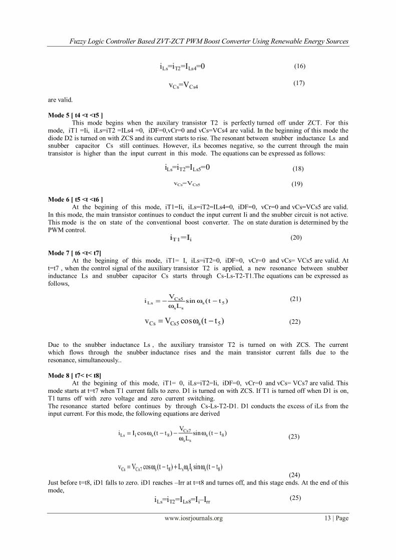
Mode 5 [ t4 <t <t5 ]
This mode begins when the auxilary transistor T2 is perfectly turned off under ZCT. For this
mode, iT1 =Ii, iLs=iT2 =ILs4 =0, iDF=0,vCr=0 and vCs=VCs4 are valid. In the beginning of this mode the
diode D2 is turned on with ZCS and its current starts to rise. The resonant between snubber inductance Ls and snubber capacitor Cs still continues. However, iLs becomes negative, so the current through the main
transistor is higher than the input current in this mode. The equations can be expressed as follows:
(18)
(19)
Mode 6 [ t5 <t <t6 ]
At the begining of this mode, iT1=Ii, iLs=iT2=ILs4=0, iDF=0, vCr=0 and vCs=VCs5 are valid.
In this mode, the main transistor continues to conduct the input current Ii and the snubber circuit is not active.
This mode is the on state of the conventional boost converter. The on state duration is determined by the
PWM control. (20)
Mode 7 [ t6 <t< t7] At the begining of this mode, iT1= I, iLs=iT2=0, iDF=0, vCr=0 and vCs= VCs5 are valid. At
t=t7 , when the control signal of the auxiliary transistor T2 is applied, a new resonance between snubber
inductance Ls and snubber capacitor Cs starts through Cs-Ls-T2-T1.The equations can be expressed as
follows,
(21)
(22)
Due to the snubber inductance Ls , the auxiliary transistor T2 is turned on with ZCS. The current
which flows through the snubber inductance rises and the main transistor current falls due to the
resonance, simultaneously..
Mode 8 [ t7< t< t8]
At the begining of this mode, iT1= 0, iLs=iT2=Ii, iDF=0, vCr=0 and vCs= VCs7 are valid. This
mode starts at t=t7 when T1 current falls to zero. D1 is turned on with ZCS. If T1 is turned off when D1 is on,
T1 turns off with zero voltage and zero current switching.
The resonance started before continues by through Cs-Ls-T2-D1. D1 conducts the excess of iLs from the input current. For this mode, the following equations are derived
(23)
(24)
Just before t=t8, iD1 falls to zero. iD1 reaches –Irr at t=t8 and turnes off, and this stage ends. At the end of this
mode, (25)

Fuzzy Logic Controller Based ZVT-ZCT PWM Boost Converter Using Renewable Energy Sources
www.iosrjournals.org 14 | Page
(26)
are valid.
Mode 9 [t8< t< t9]
This mode begins when D1 is turned off under ZCS. For this mode, iT1=0, iLs=iT2=ILs8=Ii–Irr,
iDF=0, vCr=0 and vCs=VCs8=VCs0 are valid. A resonance between parasitic capacitor Cr, snubber
inductor Ls and snubber capacitor Cs starts at t=t8. At t=t9, iLs falls to zero and the capacitor Cr is charged
from zero to VCs8 with this resonance. This mode ends by removing the control signal of the auxilary
transistor T2 . The auxilary transistor T2 is turned off with ZCS. For this mode, the following equations
are derived
(27) At the end of this mode,
(28)
(29)
are valid.
Mode 10 [ t9<t< t10]
At t=t9 , IT1=0, iLs=iT2=ILs9=0, iDF=0, vCr=VCs8 and vCs=VCs9=VCs0 are valid. During this mode,
Cr is charged linearly under the input current. For this mode,
(30) can be written. At instant t10, when the voltage across the Cr reaches output voltage Vo, the main diode DF is
turned on with ZVS and this mode finishes.
Mode 11 [ t10< t< t11]
At t=t10, iT1=0, iLs=iT2=0, iDF=0, vCr=Vo and vCs=VCs0 are valid. This mode is the off state of
the conventional boost converter. During this mode, the main diode DF continues conducting the input current
Ii and the snubber circuit is not active. The duration of this mode is determined by the PWM control. For
this mode,
(31)
III. Design Procedure In order to design the proposed ZVT-ZCT-PWM boost converter, the characteristic curves are
obtained by simulations and given in Fig.4–Fig.7. The component values used in snubber cell can be
determined from these curves. The characteristic curves are obtained depending on Ls and Cs at nominal output
power. From Fig. 4, it is seen that the maximum value of the main switch current IS1max decreases when the
value of Ls snubber inductance increases. It decreases slightly when the value of Cs snubber capacitance
increases. In Fig. 5, the initial voltage of the snubber capacitor decreases with increasing Cs, and increases
with increasing Ls.In Figure 6, the ZVT duration of the main switch is shown depending on Ls and Cs.
From the figure, it is seen that the ZVT interval decreases when Ls and Cs increases.
Fig. 4. Variation of IS1max with Ls for Fig. 5. Variation of the Vs0 with Ls for
different Cs values. different Cs value.

Fuzzy Logic Controller Based ZVT-ZCT PWM Boost Converter Using Renewable Energy Sources
www.iosrjournals.org 15 | Page
Fig .6. Variation of the tZVT with Ls for. Fig .7. Variation of tZCT with Ls for
different Cs values different Cs values.
In Figure 7, the variation of the ZCT duration of the main switch is given. The ZCT duration increases when Cs and Ls increases. The ZCT duration strongly depends on the resonance between Ls and
Cs.The smallest values of Ls and Cs components are preferred from the characteristic curves. If the
selected component values are high, the sum of the transient intervals and conduction losses increase. We have
to take into account that current stress of the main switch should remain at reasonable level.
IV. Converter Features By means of the snubber cell, the switching power losses of main switch, auxiliary switch and main
diode are reduced. The switching losses are not dissipated on the snubber cell. There is only a small
amount of circulation energy loss, which only takes a resonant period. This causes a little increase on the conduction losses of the switches. The features of the proposed ZVT-ZCT-PWM boost converter can
be summarized as follows:
1) All of the semiconductor devices are both turned on and turned off under soft switching. The main switch is
perfecetly turned on and off with ZVT and ZCT respectively. The main diode is both turned on and off
with ZVS and ZCS respectively. The auxiliary transistor is turned on with near ZCS, and turned off with ZCT.
Also, the other devices operate with soft switching.
2) All of the semiconductor devices are not subjected to any additional voltage stress.
3) The current stress of main switch is acceptable levels. The main diode is not subjected to any current
stress.
4) The converter has a simple structure and low cost. The structure of the proposed converter is
simpler than the ZVT-ZCT-PWM converters in the literature.
5) Soft switching conditions are maintained at very wide line and load ranges.
Table 1. Soft switching capabilities of the ZCT and the ZVT-ZCT converters.
V. Fuzzy Logic Controller Design In the conventional controllers like P, PI and PID, the control parameters are fixed at the time of
design. So the conventional controllers offer good performance only for the linear system. When the operating
point of the system is changed, the parameters of the conventional controllers should be designed again, and
some trials and prior information of the systems are needed to design the parameters. The FLC is used to
overcome the drawbacks of the conventional controllers [18]. The control structure of the proposed ZVT-ZCT
PWM Converter with FLC is shown.
The membership functions of the error and change in error inputs and output variables are shown in
Figs.8, 9 and 10. The membership functions are triangular shaped with 50% overlap for a precise control

Fuzzy Logic Controller Based ZVT-ZCT PWM Boost Converter Using Renewable Energy Sources
www.iosrjournals.org 16 | Page
Fig. 10. Membership function used for output variable “output”
where, the inputs and output linguistic variables called fuzzy sets are labeled as follows: NB- negative
Big, NM- Negative Medium, NS- Negative Small, Z- Zero, PS – Positive Small, PM- Positive Medium and PB-
Positive Big. The defined „if and then‟ rules produce the linguistic variables and these variables are de fuzzified
into control signals to generate PWM gating pulses for VSI. There are 49 rules are utilized to produce the
optimum control signal. The fuzzy rules used for simulation are shown in Table 2.
Table 2. Fuzzy rules e/∆e NB NM NS Z PS PM PB
NB PB PB PB PM PM PS Z
NM PB PB PM PM PS Z NS
NS PB PM PM PS Z NS NM
Z PM PM PS Z NS NM NM
PS PM PS Z NS NM NM NB
PM PS Z NS NM NM NB NB
PB Z NS NM NM NB NB NB
VI. Simulation Results To illustrate the capability of the proposed ZVT-ZCT for DC voltage, Switching operation of ZVT-
ZCT ON & OFF operation , a high voltage & current three phase grid The proposed model is simulated by
MATLAB simulink to reduce the switching losses and stable output in Load side will be given.
Fig 11.Output DC Voltage in fuzzy based ZVT-ZCT Fig 12.Output Voltage & Current in Load Side
Fig.13. Efficiency comparison of the proposed Converter

Fuzzy Logic Controller Based ZVT-ZCT PWM Boost Converter Using Renewable Energy Sources
www.iosrjournals.org 17 | Page
VII. Conclusions The Proposed a Fuzzy based PWM boost converter with a novel active snubber cell has been
analyzed in detail. This active snubber cell provides ZVT turn on and ZCT turn off together for the
main switch of the converter. Also, the proposed snubber cell is implemented by using only one quasi
resonant circuit without an important increase in cost and complexity. In the proposed converter, all
semiconductor devices are switched under soft switching. In the ZVT and ZCT processes, the auxiliary switch
is turned on under ZCS and is turned off with ZCT and near ZCS respectively. There is no additional
voltage stress across the main and auxiliary switches.The main diode is not subjected to any additional
voltage and current stresses. The operation principles and steady-state analysis of the proposed converter are
presented. In order to verify the theoretical analysis, a prototype of the proposed circuit is realized in the laboratory. Fuzzy based ZVT-ZCT-PWM boost converter using the proposed snubber cell has desired
features of the ZVT and ZCT converters. It is observed that the operation principles and the theoretical
analysis of the novel converter are measured by simulation results taken from the converter operating at
2.3 kW and 100 kHz boost converter then output voltage 400v. Additionally, at nominal output power, the
converter efficiency reaches approximately to 97.8%.
References [1] G. Hua, C. S. Leu, Y. Jiang, and F. C. Lee, “Novel Zero-Voltage-Transition PWM Converters,” IEEE Trans. on Power
Electron., vol. 9, pp. 213-219, Mar. 1994.
[2] G. Hua, E. X. Yang, Y. Jiang, and F. C. Lee, “Novel Zero-Current-Transition PWM Converters,” IEEE Trans. on Power
Electron., vol. 9, pp. 601-606, Nov. 1994.
[3] H. Mao, F. C. Lee, X. Zhou, H. Dai, M. Cosan, and D. Boroyevich, “Improved Zero-Current-Transition Converters for High-
Power Applications,” IEEE Trans. on Ind. Applicat. , vol. 33, pp. 1220-1232, Sept./Oct. 1997.
[4] J. G. Cho, J. W. Baek, G. H. Rim and I. Kang, “Novel Zero-Voltage-Transition PWM Multiphase Converters,” IEEE
Trans. on Power Electron., vol. 13, pp. 152-159, Jan. 1998.
[5] C. J. Tseng and C. L. Chen, “Novel ZVT-PWM Converters with Active Snubbers,” IEEE Trans. on Power Electron., vol.
13, pp. 861-869, Sept. 1998.
[6] V. Grigore and J. Kyyra, “A New Zero-Voltage-Transition PWM Buck Converter,” in Proc. 9th
Mediterranean
Electrotechnical Conf. (MELECON′98) , Tel Aviv, Israel, vol. 2, 1998, pp. 1241-1245.
[7] J. M. P. Menegaz, M. A. Co., D. S. L. Simonetti, and L. F. Vieira, “Improving the operation of ZVT DC -DC Converters,” in Proc.
30th Power Electron. Spec. Conf. (PESC′99) , Charleston, vol.1, 1999, pp. 293-297.
[8] K.M., Smith, and K.M., Smedley, “Properties and Synthesis of Passive Lossless Soft-Switching PWM Converters”, IEEE
Trans. on Power Electron., vol.14, pp. 890-899, Sept. 1999.
[9] C. M. de O. Stein, and H. L. Hey, “A True ZCZVT Commutation Cell for PWM Converters,” IEEE Trans. on Power
Electron., vol. 15, pp. 185-193, Jan. 2000.
[10] D. Y. Lee, B. K. Lee, S. B. Yoo, and D.S. Hyun, “An Improved Full-Bridge Zero-Voltage-Transition PWM DC/DC
Converter with Zero-Voltage / Zero-Current Switching of the Auxiliary Switches,” IEEE Trans. on Ind. Applicat., vol. 36, pp. 558-
566, Mar. / Apr. 2000.
[11] T. W. Kim, H. S. Kim, and H. W. Ahn, “An Improved ZVT PWM Boost Converter,” in Proc. 31th Power Electron. Spec.
Conf. (PESC′00) , Galway, Ireland, vol. 2, 2000, pp. 615-619.
[12] H. Bodur and A. F. Bakan, “A New ZVT-PWM DC-DC Converter,” IEEE Trans. on Power Electron., vol. 17, pp. 40-47, Jan. 2002.
[13] H. Yu, B. M. Song, and J. S. Lai, “Design of a Novel ZVT Soft-Switching Chopper,” IEEE Trans. on Power Electron., vol.
17, pp. 101-108,Jan. 2002.
[14] D.Y., Lee, M.K., Lee, D.S., Hyun, and I.,Choy, “New Zero-Current-Transition PWM DC/DC Converters Without Current Stres”,
IEEE Transactions on Power Electronics, vol.18, pp. 95-104, Jan. 2003.
[15] H., Bodur, and A.F., Bakan, “A New ZVT-ZCT-PWM DC-DC Converter,” IEEE Trans.Power Electron., vol. 19, pp. 676-684,
May. 2004.
[16] A.F., Bakan, H., Bodur, and I., Aksoy, “A Novel ZVT -ZCT PWM DC-DC Converter”, 11th Europen Conference on Power
Electronics and Applications (EPE2005), Dresden, 1-8, Sept. 2005.
[17] C.M., Wang, “Novel Zero-Voltage-Transition PWM DC-DC Converters”, IEEE Transactions on Industrial Electronics,
vol.53, pp. 254-262, Feb. 2006.
[18] W., Huang, and G., Moschopoulos, “A New Family of Zero-Voltage-Transition PWM Converters with Dual Active
Auxiliary Circuits”, Power Electronics, IEEE Transactions on, vol. 21, pp. 370-379, Mar. 2006.
[19] P., Das, and G., Moschopoulos, “A Comparative Study of Zero-Current-Transition PWM Converters”, IEEE Transactions on
Industrial Electronics, vol.54, pp. 1319-1328, June 2007.
[20] H., Wannian, G., Xing, S., Bassan, G., Moschopoulos, “Novel dual auxiliary circuits for ZVT-PWM converters”, Canadian Journal
of Electrical and Computer Engineering, vol.33, pp. 153 - 160, Summer-Fall 2008.
[21] I., Aksoy, H., Bodur, A.F., Bakan, “A New ZVT-ZCT-PWM DC–DC Converter”, IEEE Transactions on Power
Electronics,vol.25 ,pp.2093 – 2105, Aug. 2010.
[22] E., Adib, H., Farzanehfard, “Family of zero-voltage transition pulse width modulation converters with low auxiliary switch
voltage stress”, IET Power Electronics, vol.4, pp.447 - 453, April 2011
[23] Wuhua Li; Yi Zhao; Yan Deng; Xiangning He, “Interleaved Converter With Voltage Multiplier Cell for High Step-Up and
High-Efficiency Conversion”, IEEE Transactions on Power Electronics, vol.25 , pp. 2397 – 2408, Sept. 2010.
[24] Yi Zhao; Wuhua Li; Yan Deng; Xiangning He, „Analysis, Design, and Experimentation of an Isolated ZVT Boost
Converter With Coupled Inductors‟, IEEE Transactions on Power Electronics, vol.26 , pp.541 – 550,Feb. 2011
[25] Li, W.; Li, W.; He, X., “Zero-voltage transition interleaved high step-up converter with built-in transformer”, IET Power
Electronics, vol.4, pp.523 – 531, May. 2011.


![053035-SE E843 C[1-8] - Mitsubishi Electric...(Note 1) When Sensitive Earth OC/Sensitive Directional Earth OC using ZCT is required, please select ZCT type for Zero sequence current](https://static.fdocuments.us/doc/165x107/5ea0b68eed36ee623739c36c/053035-se-e843-c1-8-mitsubishi-electric-note-1-when-sensitive-earth-ocsensitive.jpg)