Fuzzy Controller based Pothole Detection System - IJCTA · Fuzzy Controller based Pothole Detection...
5
Fuzzy Controller based Pothole Detection System Savni Ankalikar 1 Tania Bhatia 1 Shreya Chowdhary 1 M.Mani Roja 2 1 Students, Electronics and Telecommunication Department 2 Associate Professor, Electronics and Telecommunication Department 1,2 Thadomal Shahani Engineering College E-mail:[email protected] Abstract Potholes are encountered frequently on roads and highways which experience wear due to constant vehicular traffic and weather conditions. These potholes are a top cause for the increasing number of accidents which may be fatal. In order to provide a solution to this problem, this paper proposes the design of the Pothole Detection System which senses the potholes and assists the driver to avoid them using Fuzzy Logic Controller. The system will detect potholes at a distance with the help of a camera mounted on the car. The controller will then inform the system about the braking power to be used. This will help to avoid accidents due to unexpected hurdles (potholes). 1. Introduction The worsening conditions of the roads are a major concern of the road development authorities. The increasing number of accidents has raised an alarm among the authorities. Majority of the road mishaps are triggered by potholes. Even the potholes that seem to be small can cause damage and put strain on the car’s suspension. They may cause buckled wheels, wastage of fuel and wear and tear of the vehicle. When a vehicle goes over a big pothole, the vehicle may not be able to handle the blow. This unexpected impact causes the driver to lose control on the vehicle causing car accidents which may be fatal. In order to avoid such incidents, data needs to be collected, analyzed and processed related to the road conditions which will alert the driver and help avoid any damage and mishaps. 2. Proposed System A fuzzy logic controller [1-3] can be used for this purpose. In this system, the size of the pothole and the speed of the vehicle are considered as the parameters in deciding the braking power needed to avoid the impact of the pothole. For gathering the information, a high resolution camera is mounted on the front end of a car which will capture images of the road. The captured images will be used to measure the perpendicular diameters of the potholes and the pothole size can thus be calculated. This pothole size will then be compared to a reference threshold pothole size. Based on the captured images and the speed of the vehicle, the system generates an alert for the driver. Depending on this information the braking power is decided to avoid the impact of the potholes and hence accidents. 2.1 Fuzzy Logic Controller Fuzzy logic controller [1-3] uses fuzzy logic and fuzzy set theory. Fuzzy sets have values between 0 and 1 both inclusive whereas crisp sets have only two values 0 and 1. Fuzzification is a process which converts crisp values into fuzzy values. Defuzzification is the inverse process. The fuzzy controller has five main units: Fuzzifier, Fuzzy Rule Base, Fuzzy Knowledge Base, Inference Engine (Decision making unit) and Defuzzifier. The decision making unit is the kernel of fuzzy logic controller. The rule base stores the knowledge about the operation. The knowledge base has the membership values of the input fuzzy sets. Figure 1. Block diagram of Fuzzy Inference System. Tania Bhatia et al, Int.J.Computer Technology & Applications,Vol 5 (5),1763-1767 IJCTA | Sept-Oct 2014 Available [email protected] 1763 ISSN:2229-6093
Transcript of Fuzzy Controller based Pothole Detection System - IJCTA · Fuzzy Controller based Pothole Detection...

Fuzzy Controller based Pothole Detection System
Savni Ankalikar
1Tania Bhatia
1Shreya Chowdhary
1M.Mani Roja
2
1Students, Electronics and Telecommunication Department
2Associate Professor, Electronics and Telecommunication Department
1,2Thadomal Shahani Engineering College
E-mail:[email protected]
Abstract
Potholes are encountered frequently on roads and
highways which experience wear due to constant
vehicular traffic and weather conditions. These
potholes are a top cause for the increasing number of
accidents which may be fatal. In order to provide a
solution to this problem, this paper proposes the design
of the Pothole Detection System which senses the
potholes and assists the driver to avoid them using
Fuzzy Logic Controller. The system will detect potholes
at a distance with the help of a camera mounted on the
car. The controller will then inform the system about
the braking power to be used. This will help to avoid
accidents due to unexpected hurdles (potholes).
1. Introduction
The worsening conditions of the roads are a major
concern of the road development authorities. The
increasing number of accidents has raised an alarm
among the authorities. Majority of the road mishaps are
triggered by potholes. Even the potholes that seem to
be small can cause damage and put strain on the car’s
suspension. They may cause buckled wheels, wastage
of fuel and wear and tear of the vehicle. When a vehicle
goes over a big pothole, the vehicle may not be able to
handle the blow. This unexpected impact causes the
driver to lose control on the vehicle causing car
accidents which may be fatal. In order to avoid such
incidents, data needs to be collected, analyzed and
processed related to the road conditions which will alert
the driver and help avoid any damage and mishaps.
2. Proposed System
A fuzzy logic controller [1-3] can be used for this
purpose. In this system, the size of the pothole and the
speed of the vehicle are considered as the parameters in
deciding the braking power needed to avoid the impact
of the pothole. For gathering the information, a high
resolution camera is mounted on the front end of a car
which will capture images of the road. The captured
images will be used to measure the perpendicular
diameters of the potholes and the pothole size can thus
be calculated. This pothole size will then be compared
to a reference threshold pothole size. Based on the
captured images and the speed of the vehicle, the
system generates an alert for the driver. Depending on
this information the braking power is decided to avoid
the impact of the potholes and hence accidents.
2.1 Fuzzy Logic Controller
Fuzzy logic controller [1-3] uses fuzzy logic and fuzzy
set theory. Fuzzy sets have values between 0 and 1 both
inclusive whereas crisp sets have only two values 0 and
1. Fuzzification is a process which converts crisp
values into fuzzy values. Defuzzification is the inverse
process. The fuzzy controller has five main units:
Fuzzifier, Fuzzy Rule Base, Fuzzy Knowledge Base,
Inference Engine (Decision making unit) and
Defuzzifier. The decision making unit is the kernel of
fuzzy logic controller. The rule base stores the
knowledge about the operation. The knowledge base
has the membership values of the input fuzzy sets.
Figure 1. Block diagram of Fuzzy Inference System.
Tania Bhatia et al, Int.J.Computer Technology & Applications,Vol 5 (5),1763-1767
IJCTA | Sept-Oct 2014 Available [email protected]
1763
ISSN:2229-6093
Example: Consider a Washing Machine. IF the dirt
is “more” THEN washing time is “high”. In this
case the input is dirt on the clothes and the output is
washing time. The input to the controller can be a
fuzzy value or a crisp value but the output always
has to be a crisp value. Therefore, a defuzzifier is
used to perform defuzzification. This design uses
Mamdani Fuzzy Inference System. This system
was proposed by Ebrahim Mamdani in 1975 to
control a system and boiler combination by a set of
fuzzy rules obtained from people working on the
system. It uses a two-rule system where each rule
consists of two inputs (antecedents) and one output
(consequent).A fuzzy system with two inputs x1
and x2 and a single output y is described by a
collection of r linguistic IF-then proposition in
Mamdani form. If x1 is A1k and x2 is A2
k then y is
Bk for k = 1, 2,..,r. Where A1
k and A2
k are the fuzzy
sets representing the kth
antecedent pairs and Bk is
the fuzzy set representing the kth
consequent. There
are two cases of Mamdani system: Max-min
Inference and Max product Inference. This design
uses Max-Min Inference. For the crisp input values
x1 and x2 the membership values will be described
by µ(x1) = 1 where x1 = input (i)
µ(x2) = 1 where x2 = input(j)
µBk(y) = max [min [µA1
k(input i), µA2
k(input j)]]
where k = 1, 2,..,r To find the crisp value of the
aggregated output, some defuzzification method
should be used to get y* (defuzzified value).
Generally, center of area and mean of maximum
methods are used for defuzzification.
2.2 Implementation of the System
The implementation of the system involves the
analysis of the input parameters and the output
parameters.
The system is designed considering the two input
descriptors as given below:
The input parameters are speed of the vehicle and
size of the pothole.
Table 1. Speed(kmph).
Speed’s
descriptors
Symbol
Slow S
Medium M
Fast F
The input Speed varies from 0 to 100kmph
(kilometers per hour). It is classified into three
descriptors: Slow, Medium and High as shown in
the table 1.
Figure 2. Membership values of Speed (input
layer).
Table 2. Size of Pothole (percentage).
Size’s
descriptors
Symbol
Small S
Medium M
Big B
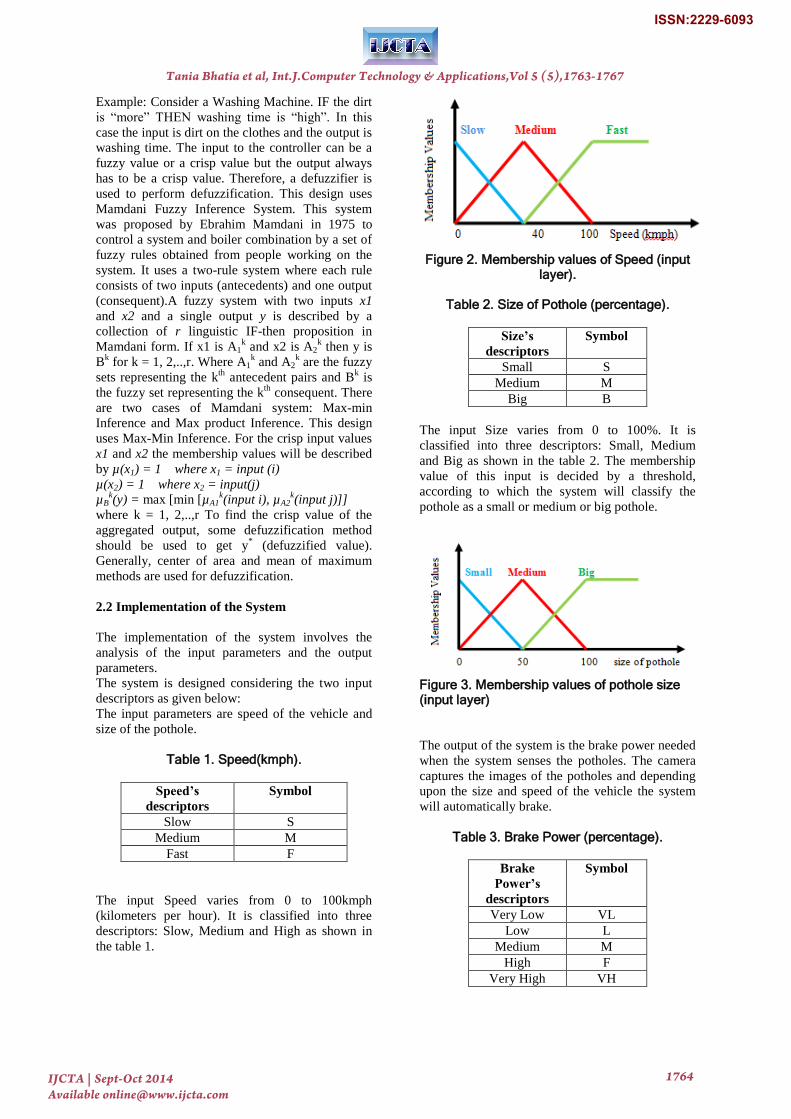
The input Size varies from 0 to 100%. It is
classified into three descriptors: Small, Medium
and Big as shown in the table 2. The membership
value of this input is decided by a threshold,
according to which the system will classify the
pothole as a small or medium or big pothole.
Figure 3. Membership values of pothole size (input layer)
The output of the system is the brake power needed
when the system senses the potholes. The camera
captures the images of the potholes and depending
upon the size and speed of the vehicle the system
will automatically brake.
Table 3. Brake Power (percentage).
Brake
Power’s
descriptors
Symbol
Very Low VL
Low L
Medium M
High F
Very High VH
Tania Bhatia et al, Int.J.Computer Technology & Applications,Vol 5 (5),1763-1767
IJCTA | Sept-Oct 2014 Available [email protected]
1764
ISSN:2229-6093
The output Braking power varies from 0 to 100%.
It is classified into five descriptors: Very Low,
Low, Medium, High and Very High as shown in
the table 3.
Figure 4. Membership values of Braking power
(output layer).
According to the diagrams, the equations of the
various descriptors are written as follows:
The membership functions of the input parameters
are expressed within the range of values of the
parameter. The membership functions for the input
parameter speed are mentioned below. The speed is
measured in kilometers per hour. Thus the range of
x varies from 0 kmph to 100 kmph.
The speed of the vehicle is slow:
0 ≤ x < 40 (1)
The speed of the vehicle is medium:
0 ≤ x ≤ 40 (2)
40 ≤ x ≤ 100 (3)
The speed of the vehicle is fast:
40 ≤ x ≤ 100 (4)
The membership functions of the input parameter
size of the pothole are expressed as mentioned
below. The size of the pothole is measured as a
percentage with respect to the reference pothole
size and hence y varies from 0 to 100 percent.
The size of the pothole is small:
0 ≤ y ≤ 50 (5)
The size of the pothole is medium:
0 ≤ y ≤ 50 (6)
50 ≤ y ≤ 100 (7)
The size of the pothole is big:
50 ≤ y ≤ 100 (8)
The membership functions of output parameter
braking speed are expressed using the equations
mentioned below. The variable used for the output
parameter is z. the brake power is measured in
percentage. Thus the range of z varies from 0 to
100 percent.
The braking power is very low:
0 ≤ z ≤ 20 (9)
The braking power is Low:
0 ≤ z ≤ 20 (10)
20 ≤ z ≤ 45(11)
The braking power is medium:
20 ≤ z ≤ 45 (12)
45 ≤ z ≤ 75 (13)
The braking power is high:
45 ≤ z ≤ 75 (14)
75 ≤ z ≤ 100 (15)
The braking power is very high:
75 ≤ z ≤ 100 (16)
Table 4: Rule Base
Speed/
Size
Slow Medium Fast
Small VL L M
Medium L M H
Big M H VH
Tania Bhatia et al, Int.J.Computer Technology & Applications,Vol 5 (5),1763-1767
IJCTA | Sept-Oct 2014 Available [email protected]
1765
ISSN:2229-6093
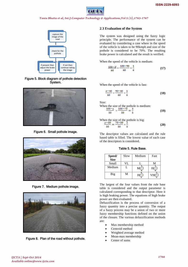
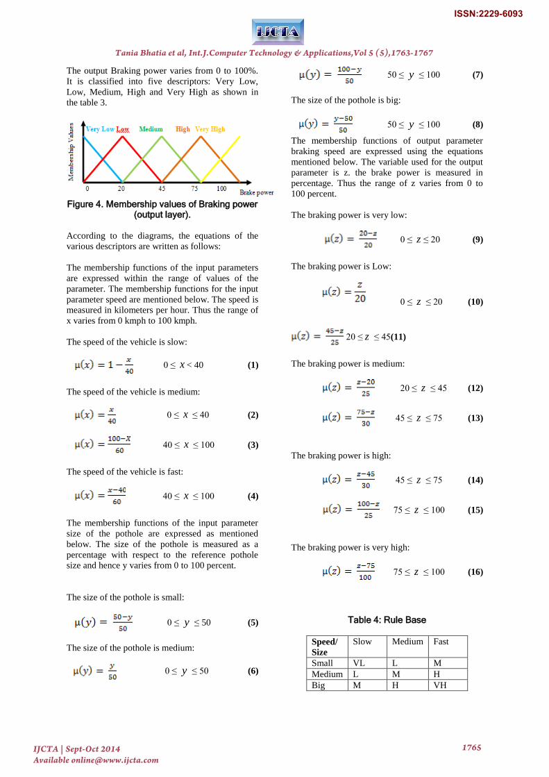
Figure 5. Block diagram of pothole detection System.
Figure 6. Small pothole image.
Figure 7. Medium pothole image.
Figure 8. Plan of the road without pothole.
2.3 Evaluation of the System
The system was designed using the fuzzy logic
principle. The performance of the system can be
evaluated by considering a case where in the speed
of the vehicle is taken to be 90kmph and size of the
pothole is considered to be 70%. The resulting
brake power is calculated and the result is verified.
When the speed of the vehicle is medium:
= = (17)
When the speed of the vehicle is fast:
= = (18)
Size:
When the size of the pothole is medium:
= (19)
When the size of the pothole is big:
= (20)
The descriptor values are calculated and the rule
based table is filled. The lowest value of each case
of the descriptors is considered.
Table 5. Rule Base.
Speed/
Size
Slow Medium Fast
Small VL L M
Medium L M( H(
Big M H( VH(
The largest of the four values from the rule base
table is considered and the output parameter is
calculated corresponding to that descriptor. Here it
is high braking power. The equations of high brake
power are then evaluated.
Defuzzification is the process of conversion of a
fuzzy quantity into a precise quantity. The output
of a fuzzy process may be a union of two or more
fuzzy membership functions defined on the union
of the closure. The various defuzzification methods
are:
Max membership method
Centroid method
Weighted average method
Mean-max membership
Center of sums
capture the image of the
road
check for the pothole
if present then adjust the brake
power
if not then continue taking
the image
Tania Bhatia et al, Int.J.Computer Technology & Applications,Vol 5 (5),1763-1767
IJCTA | Sept-Oct 2014 Available [email protected]
1766
ISSN:2229-6093

Center of largest area
First of maxima, last of maxima.
Here, there are two equations corresponding to high
brake power. So for convenience, the mean-max
method is implemented. The mean of both the
results is found and that is our final answer.
For high brake power:
(21)
Hence, Z=56
(22)
Hence, Z=95
Mean of z = 75.5
This value corresponds to high braking power as
we have concluded from the rule base table. The
driver must use 75.5% of braking to go over a
pothole of big size (i.e. 70%) at a speed of 90kmph.
Thus, the system performance is verified.
Figure 9. Block diagram of system.
The entire system consists of four units: The
camera, the evaluation unit, the control unit and the
braking system. This system provides automatic
control of the braking unit when a pothole is
detected. The control unit shifts the control from
the driver to the system. The evaluation unit
evaluates the pothole size and the speed of the
vehicle. The simultaneous operation of all the units
would make the proposed system efficient.
3. Result and Analysis
The pixel information from the camera is used to
detect the presence of pothole. The images also
provide the size of the pothole. Depending upon the
speed and the size of the pothole, the output brake
power is evaluated in the evaluation unit. In the
above evaluated case, a high brake power is
required. This information is conveyed to the
control unit. The control unit transfers the control
from the driver to the automatic system.
4. Conclusion
A Pothole Detection system to avoid the effect of
pothole was designed to reduce the loss of human
life and damage to the vehicles. The system takes
image of the pothole with the help of a high
resolution camera. The image is used to measure
the diameter of the pothole and this diameter is
compared with a reference diameter. The size of the
pothole is decided to be small, medium or big.
Depending upon the pothole size the braking power
(low, medium, high, very high) is decided and the
control unit controls the braking power. This will
prevent many accidents caused due to potholes.
This addition will improve the performance of the
system and can be used for driverless cars.
5. References
[1] S.N. Sivanandan and S.N. Deepa, “Principles
of soft computing” -2 edition by Wiley India
Ltd., First Indian Edition, 2007.
[2] Timothy J. Ross, “Fuzzy Logic with
Engineering Applications” by McGraw-Hill
[3] Simon Haykin, “Neural Networks A
Comprehensive Foundation” -2nd edition by
Pearson
[4] C. N.V. Abhinandan Reddy, M.Mani Roja,
C.N.V. Anusha Reddy “Fuzzy Logic Inference
System to Control Speed and Direction of a
Vehicle to Avoid Collision” Int.J.Computer
Technology & Applications,Vol 4 (6),996-
1000.
[5] http://www.comsol.com/blogs/infraredpothole-
repair-permanent-solution/ date:15/9/2014.
[6] http://images.wisegeek.com/pothole.jpgdate:15
/9/2014.
[7] http://www.ilcak.com/Graphics/Project_history
/HRR_bia/HRR.jpg date:15/9/2014.
Tania Bhatia et al, Int.J.Computer Technology & Applications,Vol 5 (5),1763-1767
IJCTA | Sept-Oct 2014 Available [email protected]
1767
ISSN:2229-6093


![Learning a Fuzzy Controller by Genetic Algorithms · A fuzzy controller consists of a set of fuzzy control rules with appropriate inference mechanisms [1]. The fuzzy controller is](https://static.fdocuments.us/doc/165x107/5fdb09ef9cebd6099d5e2885/learning-a-fuzzy-controller-by-genetic-a-fuzzy-controller-consists-of-a-set-of-fuzzy.jpg)


