Fuzzing Hardware Like Software - arXiv
15
Fuzzing Hardware Like Software Timothy Trippel, Kang G. Shin Computer Science & Engineering University of Michigan Ann Arbor, MI {trippel,kgshin}@umich.edu Alex Chernyakhovsky, Garret Kelly, Dominic Rizzo OpenTitan Google, LLC Cambridge, MA {achernya,gdk,domrizzo}@google.com Matthew Hicks Computer Science Virginia Tech Blacksburg, VA [email protected] Abstract—Hardware flaws are permanent and potent: hard- ware cannot be patched once fabricated, and any flaws may undermine even formally verified software executing on top. Consequently, verification time dominates implementation time. The gold standard in hardware Design Verification (DV) is concentrated at two extremes: random dynamic verification and formal verification. Both techniques struggle to root out the subtle flaws in complex hardware that often manifest as security vulnerabilities. The root problem with random verification is its undirected nature, making it inefficient, while formal verification is constrained by the state-space explosion problem, making it infeasible to apply to complex designs. What is needed is a solution that is directed, yet under-constrained. Instead of making incremental improvements to existing hard- ware verification approaches, we leverage the observation that existing software fuzzers already provide such a solution; we adapt it for hardware verification, thus leveraging existing—more advanced—software verification tools. Specifically, we translate RTL hardware to a software model and fuzz that model. The central challenge we address is how best to mitigate the differences between the hardware execution model and software execution model. This includes: 1) how to represent test cases, 2) what is the hardware equivalent of a crash, 3) what is an appropriate coverage metric, and 4) how to create a general- purpose fuzzing harness for hardware. To evaluate our approach, we design, implement, and open- source a Hardware Fuzzing Pipeline that enables fuzzing hard- ware at scale, using only open-source tools. Using our pipeline, we fuzz four IP blocks from Google’s OpenTitan Root-of-Trust chip. Our experiments reveal a two orders-of-magnitude reduction in run time to achieve Finite State Machine (FSM) coverage over traditional dynamic verification schemes. Moreover, with our design-agnostic harness, we achieve over 88% HDL line coverage in three out of four of our designs—even without any initial seeds. Index Terms—Hardware Security, Design Verification, Fuzzing I. I NTRODUCTION As Moore’s Law [1] and Dennard scaling [2] come to a crawl, hardware engineers must tailor their designs for specific applications in search of performance gains [3]–[7]. As a result, hardware designs become increasingly unique and complex. For example, the Apple A11 Bionic System- on-Chip (SoC), released over three years ago in the iPhone 8, The project depicted is sponsored in part by the Defense Advanced Research Projects Agency, and the National Science Foundation under Grant CNS- 1646130. The content of the information does not necessarily reflect the position or the policy of the Government, and no official endorsement should be inferred. Approved for public release; distribution is unlimited. Prior Work Software Test Generator Software Fuzzer Hardware HW Fuzzing HW à SW DUT Model DUT DUT =Inject Coverage Tracing Instrumentation Generic TB Custom Coverage Tracing TB Fig. 1. Fuzzing Hardware Like Software. Unlike prior Coverage Directed Test Generation (CDG) techniques [15]–[18], we advocate for fuzzing soft- ware models of hardware directly, with a generic harness (testbench) and feature rich software fuzzers. In doing so, we address the barriers to realizing widespread adoption of CDG in hardware DV: 1) efficient coverage tracing, and 2) design-agnostic testing. contains over 40 specialized Intellectual Property (IP) blocks, a number that doubles every four years [8]. Unfortunately, due to the state-explosion problem, increasing design com- plexity increases Design Verification (DV) complexity, and therefore, the probability for design flaws to percolate into products. Since 1999, 247 total Common Vulnerability Exposures (CVEs) have been reported for Intel products, and of those, over 77% (or 191) have been reported in the last four years [9]. While this may come as no surprise, given the onslaught of speculative execution attacks over the past few years [10]–[14], it highlights the correlation between hardware complexity and design flaws. Even worse, hardware flaws are permanent and potent. Un- like software, there is no general-purpose patching mechanism for hardware. Repairing hardware is both costly, and repu- tationally damaging [19]. Moreover, hardware flaws subvert even formally verified software that sits above [20]. Therefore, detecting flaws in hardware designs before fabrication and de- ployment is vital. Given these incentives, it is no surprise that hardware engineers often spend more time verifying their de- signs, than implementing them [21], [22]. 1 Unfortunately, the 1 It is estimated that up to 70% of hardware development time is spent verifying design correctness [22]. 1 arXiv:2102.02308v1 [cs.AR] 3 Feb 2021
Transcript of Fuzzing Hardware Like Software - arXiv

Fuzzing Hardware Like SoftwareTimothy Trippel, Kang G. ShinComputer Science & Engineering
University of MichiganAnn Arbor, MI
{trippel,kgshin}@umich.edu
Alex Chernyakhovsky, Garret Kelly,Dominic Rizzo
OpenTitanGoogle, LLC
Cambridge, MA{achernya,gdk,domrizzo}@google.com
Matthew HicksComputer Science
Virginia TechBlacksburg, VA
Abstract—Hardware flaws are permanent and potent: hard-ware cannot be patched once fabricated, and any flaws mayundermine even formally verified software executing on top.Consequently, verification time dominates implementation time.The gold standard in hardware Design Verification (DV) isconcentrated at two extremes: random dynamic verification andformal verification. Both techniques struggle to root out thesubtle flaws in complex hardware that often manifest as securityvulnerabilities. The root problem with random verification is itsundirected nature, making it inefficient, while formal verificationis constrained by the state-space explosion problem, making itinfeasible to apply to complex designs. What is needed is asolution that is directed, yet under-constrained.
Instead of making incremental improvements to existing hard-ware verification approaches, we leverage the observation thatexisting software fuzzers already provide such a solution; weadapt it for hardware verification, thus leveraging existing—moreadvanced—software verification tools. Specifically, we translateRTL hardware to a software model and fuzz that model.The central challenge we address is how best to mitigate thedifferences between the hardware execution model and softwareexecution model. This includes: 1) how to represent test cases,2) what is the hardware equivalent of a crash, 3) what is anappropriate coverage metric, and 4) how to create a general-purpose fuzzing harness for hardware.
To evaluate our approach, we design, implement, and open-source a Hardware Fuzzing Pipeline that enables fuzzing hard-ware at scale, using only open-source tools. Using our pipeline, wefuzz four IP blocks from Google’s OpenTitan Root-of-Trust chip.Our experiments reveal a two orders-of-magnitude reduction inrun time to achieve Finite State Machine (FSM) coverage overtraditional dynamic verification schemes. Moreover, with ourdesign-agnostic harness, we achieve over 88% HDL line coveragein three out of four of our designs—even without any initial seeds.
Index Terms—Hardware Security, Design Verification, Fuzzing
I. INTRODUCTION
As Moore’s Law [1] and Dennard scaling [2] come toa crawl, hardware engineers must tailor their designs forspecific applications in search of performance gains [3]–[7].As a result, hardware designs become increasingly uniqueand complex. For example, the Apple A11 Bionic System-on-Chip (SoC), released over three years ago in the iPhone 8,
The project depicted is sponsored in part by the Defense Advanced ResearchProjects Agency, and the National Science Foundation under Grant CNS-1646130. The content of the information does not necessarily reflect theposition or the policy of the Government, and no official endorsement shouldbe inferred. Approved for public release; distribution is unlimited.
Prio
r Wor
k
Software
Test Generator
Software Fuzzer
Hardware
HW F
uzzin
g
HW à
SW
DUT Model DUT
DUT
=Inject Coverage Tracing Instrumentation
Gene
ric T
B
Custom Coverage Tracing TB
Fig. 1. Fuzzing Hardware Like Software. Unlike prior Coverage DirectedTest Generation (CDG) techniques [15]–[18], we advocate for fuzzing soft-ware models of hardware directly, with a generic harness (testbench) andfeature rich software fuzzers. In doing so, we address the barriers to realizingwidespread adoption of CDG in hardware DV: 1) efficient coverage tracing,and 2) design-agnostic testing.
contains over 40 specialized Intellectual Property (IP) blocks,a number that doubles every four years [8]. Unfortunately,due to the state-explosion problem, increasing design com-plexity increases Design Verification (DV) complexity, andtherefore, the probability for design flaws to percolateinto products. Since 1999, 247 total Common VulnerabilityExposures (CVEs) have been reported for Intel products, andof those, over 77% (or 191) have been reported in the lastfour years [9]. While this may come as no surprise, given theonslaught of speculative execution attacks over the past fewyears [10]–[14], it highlights the correlation between hardwarecomplexity and design flaws.
Even worse, hardware flaws are permanent and potent. Un-like software, there is no general-purpose patching mechanismfor hardware. Repairing hardware is both costly, and repu-tationally damaging [19]. Moreover, hardware flaws subverteven formally verified software that sits above [20]. Therefore,detecting flaws in hardware designs before fabrication and de-ployment is vital. Given these incentives, it is no surprise thathardware engineers often spend more time verifying their de-signs, than implementing them [21], [22].1 Unfortunately, the
1It is estimated that up to 70% of hardware development time is spentverifying design correctness [22].
1
arX
iv:2
102.
0230
8v1
[cs
.AR
] 3
Feb
202
1

multitude of recently-reported hardware vulnerabilities [10]–[14], [23] suggests current efforts are insufficient.
To address the threat of design flaws in hardware, engi-neers deploy two main DV strategies: 1) dynamic and 2)formal. At one extreme, dynamic verification involves drivingconcrete input sequences into a Design Under Test (DUT)during simulation, and comparing the DUT’s behavior to aset of invariants, or gold model. The most popular dynamicverification technique in practice today is known as Con-strained Random Verification (CRV) [24]–[27]. CRV attemptsto decrease the manual effort required to develop simula-tion test cases by randomizing input sequences in the hopesof automatically maximizing exploration of the DUT state-space. At the opposite extreme, formal verification involvesproving/disproving properties of a DUT using mathematicalreasoning like (bounded) model checking and/or deductivereasoning. While (random) dynamic verification is effective atidentifying surface flaws in even complex designs, it strugglesto penetrate deep into a designs state space. In contrast, formalverification is effective at mitigating even deep flaws in smallhardware designs, but fails, in practice, against larger designs.
In search of a hybrid approach to bridge these DV ex-tremes, researchers have ported software testing techniquesto the hardware domain in hopes of improving hardware testgeneration to maximize coverage. In the hardware domain,these approaches are referred to as CDG [15], [18], [22], [24],[25], [28]–[32]. Like their software counterparts, CDG tech-niques deploy coverage metrics—e.g., Hardware DescriptionLanguage (HDL) line, Finite State Machine (FSM), functional,etc.—in a feedback loop to generate tests that further increasestate exploration.
While promising, why has CDG not seen widespread adop-tion in hardware DV? As Laeufer et al. point out [15], thisis likely fueled by several key technical challenges, result-ing from dissimilarities between software and hardwareexecution models. First, unlike software, Register TransferLevel (RTL) hardware is not inherently executable. Hardwaredesigns must be simulated, after being translated to a softwaremodel and combined with a design-specific testbench andsimulation engine, to form a Hardware Simulation Binary(HSB) (Fig. 2). This level of indirection, increases both thecomplexity and computational effort in tracing test coverageof the hardware. Second, unlike most software, hardwarerequires sequences of structured inputs to drive meaningfulstate transitions, that must be tailored to each DUT. Forexample, while most software often accepts input in the formof a fixed set of file(s) that contain a loosely-structured setof bytes (e.g., a JPEG or PDF), hardware often accepts inputfrom an ongoing stream of bus transactions. Together, thesechallenges have resulted in CDG approaches that implementcustom: 1) coverage-tracing techniques that still suffer frompoor scalability [15], [25], and 2) test generators that havelimited compatibility to a small class of DUTs, e.g., proces-sors [16], [18], [32].
To supplement traditional dynamic verification methods,we propose an alternative CDG technique we call Hardware
Fuzzing. Rather than translating software testing methodsto the hardware domain, we advocate for translatinghardware designs to software models and fuzzing thosemodels directly (Fig. 1). While fuzzing hardware in thesoftware domain eliminates coverage-tracing bottlenecks ofprior CDG techniques [15], [16], [25], since software can beinstrumented at compile time to trace coverage, it does notinherently solve the design compatibility issue. Moreover, itcreates other challenges we must address. Specifically, to fuzzhardware like software, we must adapt software fuzzers to:
1) interface with HSBs that: a) contain other componentsbesides the DUT, and b) require unique initialization.
2) account for differences between how hardware and soft-ware process inputs, and its impact on exploration depth.
3) design a general-purpose fuzzing harness and a suitablegrammar that ensures meaningful mutation.
To address these challenges, we first propose (and evaluate)strategies for interfacing software fuzzers with HSBs thatoptimize performance and trigger the HSB to crash upondetection of incorrect hardware behavior. Second, we showthat maximizing code coverage of the DUT’s software model,by construction, maximizes hardware code coverage. Third,we design an interface to map fuzzer-generated test-cases tohardware input ports. Our interface is built on the observationthat unlike most software, hardware requires piecing togethera sequence of inputs to effect meaningful state transitions.Lastly, we propose a new interface for fuzzing hardwarein a design agnostic manner: the bus interface. Moreover,we design and implement a generic harness, and create acorresponding grammar that ensures meaningful mutations tofuzz bus transactions. Fuzzing at the bus interface solves thefinal hurdle to realizing widespread deployability of CDG inhardware DV, as it enables us to reuse the same testbenchharness to fuzz any RTL hardware that speaks the same busprotocol, irrespective of the DUT’s design or implementation.
To demonstrate the effectiveness of our approach, wedesign, implement, and open-source a Hardware FuzzingPipeline (HWFP) [33], inspired by Google’s OSS-Fuzz [34],capable of fuzzing RTL hardware at scale (Fig. 5). Using ourHWFP we compare Hardware Fuzzing against a conventionalCRV technique when verifying over 480 variations of asequential FSM circuit. Across our experiments, we observeover two orders-of-magnitude reduction in time to reach fullFSM coverage by fuzzing hardware like software. Moreover,using our bus-specific hardware fuzzing grammar, we fuzzfour commercial IP cores from Google’s OpenTitan siliconRoot-of-Trust (RoT) [35]. Even without seeding the fuzzer,we achieve over 88% HDL line coverage after only 1-hour offuzzing on three of the four cores.
In summary, we:
• propose deploying feature-rich software fuzzers as a CDGapproach to solve inefficiencies in hardware DV (§III);
• provide empirically-backed guidance on how to: 1) isolatethe DUT portion of HSBs, and 2) minimize overhead ofpersistent hardware resets, for fuzzing (§III-B1 & §V-C);
2

• develop a technique to map fuzzer-generated testcasesacross both space and time to create a sequence of inputsto stimulate software models of hardware (§III-B2);
• design and evaluate several bus-specific HardwareFuzzing harnesses and grammars to facilitate fuzzing allbus-based hardware cores (§III-B3, §III-B4 & §VI-B);
• design, implement, and open-source a HWFP [33] thatcontinuously fuzzes RTL hardware at scale on GoogleCloud Platform (GCP) (§IV); and
• demonstrate Hardware Fuzzing provides two orders-of-magnitude reduction in run time to achieve comparable(or better) FSM coverage to (or than) current state-of-the-art CRV schemes (§V-D).
II. BACKGROUND
There are two main hardware verification methods: 1)dynamic and 2) formal. While there have been significantadvancements in deploying formal methods in DV work-flows [32], [35], [36], dynamic verification remains the goldstandard due to its scalability towards complex designs [15].Therefore, we focus on improving dynamic verification byleveraging advancements in the software fuzzing community.Below, we provide a brief overview of the current state-of-the-art in dynamic hardware verification, and software fuzzing.
A. Dynamic Verification of Hardware
Dynamic verification of hardware typically involves threesteps: 1) test generation, 2) hardware simulation, and 3)test evaluation. First, during test generation, a sequence ofinputs are crafted to stimulate the DUT. Next, the DUT’sbehavior—in response to the input sequence—is simulatedduring hardware simulation. Lastly, during test evaluation, theDUT’s simulation behavior is checked for correctness. Thesethree steps are repeated until all interesting DUT behaviorshave been explored. How do we know when we have exploredall interesting behaviors? To answer this question, verificationengineers measure coverage of both: 1) manually definedfunctional behaviors (functional coverage) and 2) the HDLimplementation of the design (code coverage) [37]–[39].
1) Test Generation: To maximize efficiency, DV engineersaim to generate as few test vectors as possible that still closecoverage. To achieve this goal, they deploy two main testgeneration strategies: 1) constrained-random and 2) coverage-directed. The former is typically referred to holistically asConstrained Random Verification (CRV), and the latter asCoverage Directed Test Generation (CDG). CRV is a par-tially automated test generation technique where manually-defined input sets are randomly combined into transactionsequences [26], [27]. While better than an entirely manualapproach, CRV still requires some degree of manual tuning toavoid inefficiencies, since the test generator has no knowl-edge of test coverage. Regardless, CRV remains a populardynamic verification technique today, and its principles areimplemented in two widely deployed (both commerciallyand academically) hardware DV frameworks: 1) Accellera’s
HDL à SW
Clang++
DUT
Hardware Simulation Binary (HSB)
HDL
SW
Testbench Simulation
Engine
main()
Fig. 2. Hardware Simulation Binary (HSB). To simulate hardware, theDUT’s HDL is first translated to a software model, and then compiled/linkedwith a testbench (written in HDL or software) and simulation engine to forma Hardware Simulation Binary (HSB). Executing this binary with a sequenceof test inputs simulates the behavior of the DUT.
Universal Verification Methodology (UVM) framework (Sys-temVerilog) [27] and 2) the open-source cocotb (Python)framework [40].
To overcome CRV shortcomings, researchers have proposedCDG [15]–[18], [22], [24], [25], [28]–[32], or using testcoverage feedback to drive future test generation. Unlike CRV,CDG does not randomly piece input sequences together inhopes of exploring new design state. Rather, it mutates priorinput sequences that explore uncovered regions of the designto iteratively expand the coverage boundary. Unfortunately,due to deployability challenges, e.g., slow coverage tracingand limited applicability to a small set of DUTs, CDG hasnot seen widespread adoption in practice [15]. In this paper,we recognize that existing software fuzzers provide a solutionto many of these deployability challenges, and therefore advo-cate for verifying hardware using software verification tools.The central challenges in making this possible are adaptingsoftware fuzzers to verify hardware, widening the scope ofsupported designs, and increasing automation of verification.
2) Hardware Simulation: While there are several commer-cial [45]–[47] and open-source [41], [48] hardware simulators,most work in the same general manner, as shown in Fig. 2.First, they translate hardware implementations (described inHDL) into a software model, usually in C/C++. Next, theycompile the software model and a testbench—either translatedfrom HDL, or implemented in software (C/C++)—and linkthem with a simulation engine. Together, all three componentsform an Hardware Simulation Binary (HSB) (Fig. 2) that canbe executed to simulate the design. Lastly, the HSB is executedwith the inputs from the testbench to capture the design’s be-havior. Ironically, even though commercial simulators convertthe hardware to software, they still rely on hardware-specificverification tools, likely because software-oriented tools failto work on hardware models—without the lessons in thispaper. To fuzz hardware in the software domain, we takeadvantage of the transparency in how an open-source hardwaresimulator, Verilator [41], generates an HSB. Namely, weintercept the software model of the hardware after translation,
3

HW à SW
Mutate Tests Test
Save Coverage Increasing Tests
Execute
Test
Save Crashes
Discard Un-interesting Tests
Compile / InstrumentHardware Simulation Model
Input Seeds
Input Queue
Sim. Engine
DUT
HSBDUT Model
1
2
3 4
6
5
Coverage-GuidedGreybox Fuzzer
HDL Compiler
Generic Testbench
HW Simulation Model
Fig. 3. Hardware Fuzzing. Fuzzing hardware in the software domain involves: translating the hardware DUT to a functionally equivalent software model(1) using a SystemVerilog compiler [41], compiling and instrumenting a Hardware Simulation Binary (HSB) to trace coverage (2), crafting a set of seed inputfiles (3) using our design-agnostic grammar (§ III-B4), and fuzzing the HSB with a coverage-guided greybox software fuzzer [42]–[44] (4–6).
and instrument/compile it for coverage-guided fuzzing (Fig. 3).3) Test Evaluation: After simulating a sequence of test in-
puts, the state of the hardware (both internally and its outputs)are evaluated for correctness. There are two main approachesfor verifying design correctness: 1) invariant checking and2) (gold) model checking. In invariant checking, a set ofassertions (e.g., SystemVerilog Assertions (SVAs) or softwareside C/C++ assertions) are used to check properties of thedesign have not been violated. In model checking, a separatemodel of the DUT’s correct behavior is emulated in software,and compared to the DUT’s simulated behavior. We supportsuch features and adopt both invariant violations and goldenmodel mismatches as an analog for software crashes in ourhardware fuzzer.
B. Software Fuzzing
Software fuzzing is an automated testing technique de-signed to identify security vulnerabilities in software [49].Thanks to its success, it has seen widespread adoption inboth industry [50] and open-source [34] projects. In principle,fuzzing typically involves the following three main steps [51]:1) test generation, 2) monitoring test execution, and 3)crash triaging. During test generation, program inputs aresynthesized to exercise the target binary. Next, these inputs arefed to the program under test, and its execution is monitored.Lastly, if a specific test causes a crash, that test is furtheranalyzed to find the root cause. This process is repeated untilall, or most, of the target binary has been explored. Below wecategorize fuzzers by how they implement the first two steps.
1) Test Generation: Most fuzzers generate test cases in oneof two ways, using: 1) a grammar, or 2) mutations. Grammar-based fuzzers [52]–[57] use a human-crafted grammar toconstrain tests to comply with structural requirements of aspecific target application. Alternatively, mutational fuzzerstake a correctly formatted test as a seed, and apply mutationsto the seed to create new tests. Moreover, mutational fuzzersare tuned to be either: 1) directed, or 2) coverage-guided.Directed mutational fuzzers [58]–[64] favor mutations thatexplore specific region within the target binary, i.e., prioritizing
exploration location. Conversely, coverage-guided mutationalfuzzers [42]–[44], [65]–[67] favor mutations that explore asmuch of the target binary as possible, i.e., prioritizing ex-ploration completeness. For this work, we favor the use ofmutational, coverage-guided fuzzers, as they are both design-agnostic, and regionally generic.
2) Test Execution Monitoring: Fuzzers monitor test execu-tion using one of three approaches: 1) blackbox, 2) whitebox,or 3) greybox. Fuzzers that only monitor program inputsand outputs are classified as blackbox fuzzers [52], [55],[68]. Alternatively, fuzzers that track detailed execution pathsthrough programs with fine-grain program analysis (sourcecode required) and constraint solving are known as white-box fuzzers [64], [69]–[75]. Lastly, greybox fuzzers [42],[44], [54], [56]–[59], [62], [63], [65]–[67], [76], [77] offera trade-off between black- and whitebox fuzzers by deploy-ing lightweight program analysis techniques, such as code-coverage tracing. Since Verilator [41] produces raw C++source code from RTL hardware, our approach can leverageany software fuzzing technique—white, grey, or blackbox. Inour current implementation, we deploy greybox fuzzing, dueto its popularity in the software testing community.
III. HARDWARE FUZZING
To take advantage of advances in software fuzzing forhardware DV, we propose translating hardware designs tosoftware models, and fuzzing the model directly. We call thisapproach, Hardware Fuzzing, and illustrate the process inFig. 3. Below, we first motivate our approach by describinghow hardware is already translated to the software domain forsimulation, and that software fuzzers provide a solution to akey technical challenge in CDG: scalable coverage tracing.Then, we pose several challenges in adapting software fuzzersto fuzz HSBs (in a design-agnostic fashion), and presentsolutions to overcome these challenges.
A. Why Fuzz Hardware like Software?
We observe two key benefits of fuzzing hardware in thesoftware domain. First, hardware is already translated to a
4

software model for simulation purposes (§II-A2). Second,unlike prior CDG approaches [15], [16], we recognize thatsoftware fuzzers already provide an efficient solution fortracing coverage. Below we explain how RTL hardware istranslated to executable software, and why software fuzzersimplicitly maximize hardware coverage by generating teststhat maximize coverage of the HSB.
1) Translating HDL to Software: Today, simulating RTLhardware involves translating HDL into a functionally equiv-alent software (C/C++) model that can be compiled andexecuted (§II-A2). To accomplish this, most hardware sim-ulators [41], [48] contain an RTL compiler to perform thetranslation. Therefore, we leverage a popular open-sourcehardware simulator, Verilator [41], to translate SystemVerilogHDL into a cycle-accurate C++ model for fuzzing.
Like many compilers, Verilator first performs lexical anal-ysis and parsing (of the HDL) with the help of Flex [78]and Bison [79], to generate an Abstract Syntax Tree (AST).Then, it performs a series of passes over the AST to resolveparameters, propagate constants, replace don’t cares (Xs) withrandom values, eliminate dead code, unroll loops/generatestatements, and perform several other optimizations. Finally,Verilator generates C++ (or SystemC) code representing acycle-accurate model of the hardware. It creates a C++ classfor each Verilog module, and organizes classes according tothe original HDL module hierarchy [32].
To interface with the model, Verilator exposes public mem-ber variables for each input/output to the top-level module, anda public eval() method (to be called in a loop) in the topC++ class. Each input/output member variable is mapped tosingle/arrayed bool, uint32_t, or uint64_t data types,depending on the width of each signal. Each call to eval()updates the model based on the current values assigned to top-level inputs and internal states variables. Two calls representa single clock cycle (one call for each rising and falling clockedges).
2) Tracing Hardware Coverage in Software: To efficientlyexplore a DUT’s state space, CDG techniques rely on tracingcoverage of past test cases to generate future test cases. Thereare two main categories of coverage metrics used in hardwareverification [37]–[39]: 1) code coverage, and 2) functionalcoverage. The coarsest, and most used, code coverage metric isline coverage. Line coverage measures the percentage of HDLlines that have been exercised during simulation. Alternatively,functional coverage measures the percentage of various high-level design functionalities—defined using special HDL con-structs like SystemVerilog Coverage Points/Groups—that areexercised during simulation. Regardless of the coverage metricused, tracing HDL coverage during simulation is often slow,since coverage traced in the software (simulation) domain mustbe mapped back to the hardware domain [38].
In an effort to compute DUT coverage efficiently, and in anHDL-agnostic manner, prior CDG techniques develop customcoverage metrics, e.g., multiplexer coverage [15], that canbe monitored by instrumenting the RTL directly. However,this approach has two drawbacks. First, the hardware must
be simulated on an FPGA (simulating within software is justas slow). Second, the authors provide no indication that theircustom coverage metrics actually translate to coverage metricsDV engineers care about.
Rather than make incremental improvements to existingCDG techniques, we recognize that: 1) software fuzzers pro-vide an efficient mechanism—e.g., binary instrumentation—totrace coverage of compiled C++ hardware models (HSBs), and2) characteristics of how Verilator translates RTL hardware tosoftware makes mapping software coverage to hardware cov-erage implicit. On the software side, there are three main codecoverage metrics of increasing granularity: 1) basic block, 2)basic block edges, and 3) basic block paths [51]. The mostpopular coverage-guided fuzzers—AFL [42], libFuzzer [43],and honggfuzz [44]—all trace edge coverage. On the hard-ware side, Verilator conveniently generates straight-line C++code for both blocking and non-blocking2 SystemVerilogstatements [32], and injects conditional code blocks (basicblocks) for SystemVerilog Assertions and Coverage Points.Therefore, optimizing test-generation edge coverage of thesoftware model of the hardware during simulation, translates tooptimizing both code and functional coverage of the hardwareitself. We demonstrate this artifact in §VI-B3 of our evaluation.
B. Adapting Software Fuzzers to Fuzz Hardware
While software fuzzers contain efficient mechanisms fortracing coverage of HSBs—e.g., binary instrumentation—interfacing them with HSBs, in a design-agnostic manner isnon-trivial. Below, we highlight several challenges in fuzzingHSBs with software fuzzers, and propose solutions to over-come them.
1) Interfacing Software Fuzzers with HSBs: Naıvely, aDV engineer may interface the HSB directly with a softwarefuzzer (like [42]–[44]) by compiling the HSB source codealongside the testbench harness (Algo. 1) and simulationengine with one of the fuzzer-provided wrappers for Clang.However, they would be ignoring two key differences betweentypical software applications and HSBs that may degradefuzzer performance. First, HSBs have other components—atestbench and simulation engine (Fig. 2)—that are not part ofthe DUT. While the DUT is manipulated through the testbenchand simulation engine, instrumenting all components HSBsactually degrades fuzzer performance (§V-C1). Additionally,unlike software, the DUT software model must be reset andinitialized, prior to processing any inputs. Depending on thesize of the DUT, this process can require special configurationof the testbench, i.e., initializing the fuzzer to snapshot thehardware simulation process after reset and initialization ofthe DUT (§V-C2).
2) Interpreting Fuzzer-Generated Tests: For most soft-ware, a single input often activates an entire set of statetransitions within the program. Consequently, the most popularsoftware fuzzers assume the target binary reads a single
2Verilator imposes an order on the non-blocking assignments since C++does not have a semantically equivalent assignment operator [32], [41].Regardless, this ordering does not effect code coverage.
5

dimensional input—e.g., a single image or document—fromeither a file, stdin, or a byte array [42]–[44]. Unfortunately,the execution model of hardware is different. In an HSB,a sequence of inputs is required to activate state transitionswithin the DUT. For example, a 4-digit lock (with a keypad)only has a chance of unlocking if a sequence of four inputs(test cases) are provided. Fuzzing this lock with single testcases (digits), will fail. Likewise, fuzzing HSBs with softwarefuzzers that employ a single-test-case-per-file model will alsofail. Therefore, to stimulate hardware with software fuzzers,we propose a new interface for interpreting single dimensionalfuzzer-generated tests in two dimensions: space and time. Weimplement this interface in the form of a generic fuzzingharness (testbench)—shown in Algo. 1—that continuously:1) reads byte-level portions of fuzzer-generated test files, 2)maps these bytes to hardware input ports, and 3) advancesthe simulation clock by calling the model’s eval() methodtwice, until there are no remaining bytes to process. Withour fuzzing harness, we transform one-dimensional test inputs,into a two-dimensional sequence of inputs.
Algorithm 1: Generic Hardware Fuzzing harness (testbench) thatmaps one-dimensional fuzzer-generated test files to both spatial andtemporal dimensions.
Input: fuzz test file.hwf1 dut← V top();2 tf ← open(fuzz test file.hwf);3 while tf not empty do4 foreach port ∈ dut.inputs do5 tf.read((uint 8t*) port, sizeof (port));6 for k ← 1 to 2 do7 clock ← (clock + 1)%2;8 dut.eval();9 end
10 end11 end
3) Bus-Centric Harness: While the multi-dimensionalfuzzing interface we develop enables fuzzer-generated tests toeffect state transitions in hardware, it is not design-agnostic.Specifically, the ports of a hardware model are not iterable(Algo. 1: line 4). A DV engineer would have to create aunique fuzz harness (testbench) for each DUT they verify.To facilitate DUT portability, we take inspiration from howhardware engineers interface IP cores within an SoC [80].Specifically, we propose fuzzing IP cores at the bus interfaceusing a bus-centric harness.
To implement this harness, we could alter our prior harness(Algo. 1) by mapping bytes from fuzzer-generated test files totemporal values for specific signals of a bus-protocol of ourchoice. However, this would create an exploration barrier sincebus-protocols require structured syntax, and most mutationalfuzzers lack syntax awareness [81]. In other words, the fuzzerwould likely get stuck trying to synthesize a test file, that whenmapped to spatio-temporal bus signal values, produces a validbus-transaction. Instead, we implement a harness that decodesfuzzer-generated test files into sequences of properly structuredbus transactions using a bus-centric grammar we describebelow. Our current bus-centric harness is implemented around
Opcode Address Data
32-bits 32-bits8-bitsFig. 4. Hardware Fuzzing Instruction. A bus-centric harness (testbench)reads binary Hardware Fuzzing Instructions from a fuzzer-generated testfile, decodes them, and performs TL-UL bus transactions to drive the DUT(Fig.12). Our Hardware Fuzzing Instructions comprise a grammar (Tbl. I)that aid syntax-blind coverage-guided greybox fuzzers in generating valid bus-transactions to fuzz hardware.
TABLE IHARDWARE FUZZING GRAMMAR.
Opcode AddressRequired?
DataRequired? Testbench Action
wait no no advance the clock one periodread yes no TL-UL Get (read)write yes yes TL-UL PutFullData (write)
the TileLink Uncached Lightweight (TL-UL) bus protocol [82]with a 32-bit data bus, and illustrated in Fig. 12.
4) Bus-Centric Grammar: To translate fuzzer-generatedtest files into valid bus transactions we construct a HardwareFuzzing grammar. We format our grammar in a compact binaryrepresentation to facilitate integration with popular greyboxfuzzers that produce similar formats [42]–[44]. To match ourbus-centric harness, we implement our grammar around thesame TL-UL bus protocol [82]. Our grammar consists ofHardware Fuzzing instructions (Fig. 4), that contain: 1) an 8-bit opcode, 2) 32-bit address field, and 3) 32-bit data field. Theopcode within each instruction determines the bus transactionthe harness performs. We describe the mappings betweenopcodes and TL-UL bus transactions in Table I.
Note, there are two properties of our grammar that leaveroom for various harness (testbench) implementations, whichwe study in §VI-B. First, while we define only three opcodesin our grammar, we represent the opcode with an entirebyte, leaving it up to the harness to decide how to mapHardware Fuzzing opcode values to testbench actions. We dothis for two reasons: 1) a byte is the smallest addressable unitin most software, facilitating the development of utilities toautomate generating compact binary seed files (that complywith our grammar) from high-level markdown languages, and2) choosing a larger opcode field enables adding more opcodesin the future, should we need to support additional operationsin TileLink bus protocol [82]. Second, of the three opcodes weinclude, not all require address and data fields. Therefore, itis up to the harness to decide how it should process HardwareFuzzing instructions. Should it read fixed size instructionframes? Or variable size instructions frames, depending on theopcode? To understand which interpretation of our HardwareFuzzing grammar provides optimal constraints for greyboxfuzzing, we study the performance of various binary encodingsof our grammar in §VI-B.
IV. HARDWARE FUZZING PIPELINE
To fuzz hardware at scale we design, implement, and open-source [33] a Hardware Fuzzing Pipeline (HWFP) modeledafter Google’s OSS-Fuzz (Fig. 5). First, our pipeline builds
6

Translate HW à SWCompile/Instrument HSB
Fuzz HSBExtract Final HDL Coverage
Save Data to GCSTeardown VM
GCP VM
Fuzzing Container
Fig. 5. Hardware Fuzzing Pipeline (HWFP). We design, implement, andopen-source a HWFP that is modeled after Google’s OSS-Fuzz [34]. OurHWFP enables us to verify RTL hardware at scale using only open-sourcetools, a rarity in hardware DV.
a Docker image (from the Ubuntu 20.04 base image) con-taining a compiler (LLVM version 12.0.0), RTL simulator(Verilator [41] version 4.0.4), software fuzzer, the target RTLhardware, and a generic fuzzing harness (§III-B3). From theimage, a container is instantiated on a GCP VM that:
1) translates the DUT’s RTL to a software model withVerilator [41],
2) compiles/instruments the DUT model, and links it withthe generic fuzzing harness (§III-B3) and simulationengine to create an HSB (Fig. 2),
3) launches the fuzzer for a set period of time, using thetimeout utility,
4) traces final HDL coverage of fuzzer-generated tests withVerilator [41],
5) saves fuzzing and coverage data to a Google CloudStorage (GCS) bucket, and lastly
6) tears down the VM.Note, for benchmarking, all containers are instantiated on theirown GCP n1-standard-2 VM with two vCPUs, 7.5 GBof memory, 50 GB of disk, running Google’s Container-Optimized OS. In our current implementation, we useAFL [42] (version 2.57b) as our fuzzer, but our HWFP isdesigned to be fuzzer-agnostic.
Unlike traditional hardware verification toolchains, ourHWFP uses only open-source tools, allowing DV engineersto save money on licenses, and spend it on compute. Thisnot only enhances the deployability of our approach, butmakes it ideal for adopting alongside existing hardware DVworkflows. This is important because rarely are new DVapproaches adopted without some overlap with prior (proven)techniques, since mistakes during hardware verification havecostly repercussions.
V. EVALUATION - PART 1
In the first part of our evaluation, we address two techni-cal questions around fuzzing software models of RTL hard-ware with software fuzzers. First, how should we interfacecoverage-guided software fuzzers with HSBs? Unlike mostsoftware, HSBs contain other components—a testbench andsimulation engine (Fig. 2)—that are not the target of testing,
1
Locked
2
Locked Unlocked
code == correct1 code == correct2
...reset_n ||
code != correct2
~reset_n~reset_n
code == correctn
m
log2(n)Lockreset_nclk
code
state
unlocked
reset_n || code != correct1
Lock (DUT)
unlockedcode
/dev/urandom assert(!unlocked)
Testbench (cocotb)
Lock (DUT)
unlockedcode
STDIN assert(!unlocked)Testbench (C++)
AFL Seed (empty file)
cove
rage
A) Constrained Random Verification B) Hardware Fuzzing
n
Fig. 6. Digital Lock FSM. We use a configurable digital lock (FSM shownhere) to demonstrate: 1) how to interface software fuzzers with hardwaresimulation binaries, and 2) the advantages of Hardware Fuzzing (vs. traditionalCRV). The digital lock FSM can be configured in two dimensions: 1) totalnumber of states and 2) width (in bits) of input codes.
yet the fuzzer must learn to manipulate in order to drivethe DUT. Second, how does Hardware Fuzzing compare withtraditional dynamic verification methods, i.e., CRV, in termsof time to coverage convergence? To address this first setof questions, we perform several End-to-End (E2E) fuzzinganalyses on over 480 digital lock hardware designs withvarying state-space complexities.
A. Digital Lock Hardware
In this half of our evaluation, we fuzz various configurationsof a digital lock, whose FSM and HDL are shown in Fig. 6and List. 1, respectively. We choose to study this design sincethe complexity of its state space is configurable, and therefore,ideal for stress testing various DV methodologies. Specifically,the complexity is configurable in two dimensions: 1) the totalnumber of states is configurable by tuning the size, N , ofthe single state register, and 2) the probability of choosingthe correct unlocking code sequence is adjustable by alteringthe size, M , of the comparator/mux that checks input codesagainst hard-coded (random) values (List. 1). We develop autility in Rust, using the kaze crate [83], to auto-generate480 different lock state machines of various complexities, i.e.,different values of N , M , and random correct code sequences.
B. Digital Lock HSB Architectures
To study these designs, we construct two HSB architectures(Fig. 7) using two hardware DV methodologies: CRV andHardware Fuzzing. The CRV architecture (Fig. 7A) attemptsto unlock the lock through a brute-force approach, whererandom code sequences are driven into the DUT until theunlocked state is reached. If the random sequence fails tounlock the lock, the DUT is reset, and a new random sequenceis supplied. If the sequence succeeds, an SVA is violated,which terminates the simulation. The random code sequencesare constrained in the sense that only valid code sequences aredriven into the DUT, i.e., 1) each code in the sequence is in therange [0, 2M ) for locks with M -bit code comparators, and 2)sequences contain exactly 2N−1 input codes for locks with 2N
states. The CRV testbench is implemented with the cocotb [40]framework and simulations are run with Verilator [41].
Listing 1. SystemVerilog of Lock with N=log2(# states) and M -bit codes.
1 module lock(2 input reset n ,3 input clk ,4 input [M−1:0] code,5 output unlocked
7

6 ) ;7 logic [N−1:0] state ;8 logic [M−1:0] correct codes [N];9
10 // Secret codes set to random values11 for (genvar i = 0; i < N; i++) begin : secret codes12 assign correct codes [ i ] = <random value>;13 end14
15 assign unlocked = ( state == ’1) ? 1’b1 : 1’b0;16
17 always @(posedge clk) begin18 if (! reset n ) begin19 state <= ’0;20 end else if (!unlocked && code == correct codes[state ]) begin21 state <= state + 1’b1;22 end else begin23 state <= state;24 end25 end26 endmodule
Alternatively, the Hardware Fuzzing HSB (Fig. 7B) takesinput from a software fuzzer that generates code sequencesfor the DUT. The fuzzer initializes and checkpoints, a processrunning the HSB (Fig. 2), and repeatedly forks this processand tries various code sequence inputs. If an incorrect codesequence is supplied, the fuzzer forks a new process (equiva-lent to resetting the DUT) and tries again. If the correct codesequence is provided, an SVA is violated, which the fuzzerregisters as a program crash. The difference between CRV andHardware Fuzzing is that the fuzzer traces coverage duringhardware simulation, and will save past code sequences thatget closer to unlocking the lock. These past sequences are thenmutated to generate future sequences. Thus, past inputs areused to craft more intelligent inputs in the future. To interfacethe software fuzzer with the HSB, we:
1) implement a C++ testbench harness from Algo. 1 thatreads fuzzer-generated bytes from stdin and feedsthem directly to the code input of the lock.
2) instrument the HSB containing the DUT by compilingit with afl-clang-fast++.
C. Interfacing Software Fuzzers with Hardware
There are two questions that arise when interfacing softwarefuzzers with HSBs. First, unlike most software applications,software models of hardware are not standalone binaries.They must be combined—typically by either static or dynamiclinking—with a testbench and simulation engine to form anHSB (§II-A2). Of these three components—DUT, testbench,and simulation engine—we seek to maximize coverage ofonly the DUT. We do not want to waste fuzzing cycles onthe testbench or simulation engine. Since coverage tracinginstrumentation provides an indirect method to coarsely steerthe fuzzer towards components of interest [58], it would beconsidered good practice to instrument just the DUT portionof the HSB. However, while the DUT is ultimately what wewant to fuzz, the fuzzer must learn to use the testbench andsimulation engine to manipulate the DUT. Therefore, whatcomponents of the HSB should we instrument to maximizefuzzer performance, yet ensure coverage convergence?
Lock (DUT)
unlockedcode
/dev/urandom assert(!unlocked)
Testbench (cocotb)
Lock (DUT)
unlockedcode
STDIN assert(!unlocked)Testbench (C++)
AFL Seed (empty file)
cove
rage
A) Constrained Random Verification B) Hardware Fuzzing
Hardware Simulation Binary Hardware Simulation Binary
Sim.Engine Sim.
Engine
Fig. 7. Digital Lock HSB Architectures. (A) A traditional CRV architecture:random input code sequences are driven into the DUT until the unlocked stateis reached. (B) A software fuzzer generates tests to drive the DUT. The fuzzermonitors coverage of the DUT during test execution and uses this informationto generate future tests. Both HSBs are configured to terminate execution uponunlocking the lock using an SVA in the testbench that signals the simulationengine (Fig. 2) to abort.
Second, when simulating hardware, the DUT must bereset to a clean state before it can start processing inputs.Traditionally, the testbench portion of the HSB performs thisreset by asserting the DUT’s global reset signal for a setnumber of clock cycles. Since the fuzzer instantiates, andrepeatedly forks the process executing the HSB, this resetprocess will happen hundreds, or (potentially) thousands oftimes per second as each test execution is processed. Whilesome software fuzzers [42], [43] enable users to perform ini-tialization operations before the program under test is forked—meaning the DUT reset could be performed once, as eachforking operation essentially sets the HSB back to a cleanstate—-this may not always the case. Moreover, it complicatesfuzzer–HSB integration, which contradicts the whole premiseof our approach, i.e., low-overhead, design-agnostic CDG.Therefore, we ask: is this fuzzing initialization feature requiredto fuzz HSBs?
1) Instrumenting HSBs for Fuzzing: To determine thecomponents of the HSB we should instrument, we measure thefuzzing run times to achieve approximate full FSM coverage3
of several lock designs, i.e., the time it takes the fuzzer togenerate a sequence of input codes that unlocks each lock.We measure this by modifying the fuzzer to terminate upondetecting the first crash, which we produce using a single SVAthat monitors the condition of the unlocked signal (List. 1).Specifically, using lock designs with 16, 32, and 64 states, andinput codes widths of four bits, we construct HSBs followingthe architecture shown in Fig. 7B. For each HSB, we varythe components we instrument by using different compilersettings for each component. First, we (naıvely) instrumentall components, then only the DUT. Next, we fuzz eachHSB 50 times, seeding the fuzzer with an empty file in eachexperiment.
We plot the distribution of fuzzing run times in Fig. 8.Since fuzzing is an inherently random process, we plot onlythe middle third of run times across all instrumentation levelsand lock sizes. Moreover, all run times are normalized to themedian DUT-only instrumentation run times (orange) acrosseach lock size. In addition to plotting fuzzing run times, we
3We use the term approximate when referring to full FSM coverage,since we are not excising the lock’s reset state transitions (Fig. 6) in theseexperiments.
8
8 16 32 64# states
0.5
1.0
1.5
2.0
2.5
3.0Ti
me
to F
ull F
SM
Cov
erag
e (R
elat
ive)
Components InstrumentedAllDUT only
Fig. 8. Instrumentation Level vs. Coverage Convergence Rate. Distributionof fuzzer run times required to unlock various sized digital locks (code widthsare fixed at four bits), i.e., achieve ≈ full FSM coverage. For each HSB,we vary the components we instrument for coverage tracing. Run times arenormalized to the median DUT-only instrumentation level (orange) acrosseach lock size (red line). While the fuzzer uses the testbench and simulationengine to manipulate the DUT, instrumenting only the DUT does not hinderthe coverage convergence rate of the fuzzer. Rather, it improves it when DUTsizes are small, compared to the simulation engine and testbench (Fig. 9).
plot the number of basic blocks within each component ofthe HSB in Fig. 9. Across all lock sizes, we observe that onlyinstrumenting the DUT does not handicap the fuzzer, but ratherimproves the rate of coverage convergence! In fact, we performa Mann-Whitney U test, with a 0.05 significance level, and findall the run-time improvements to be statistically significant.Moreover, we observe that even though the run-time improve-ments are less significant as the DUT size increases comparedto the simulation engine and testbench (Fig. 9), instrumentingonly the DUT never handicaps the fuzzer performance.
Key Insight: Instrumenting only the DUT portion ofthe HSB does not impair the fuzzer’s ability to drive theDUT, rather, it improves fuzzing speed.
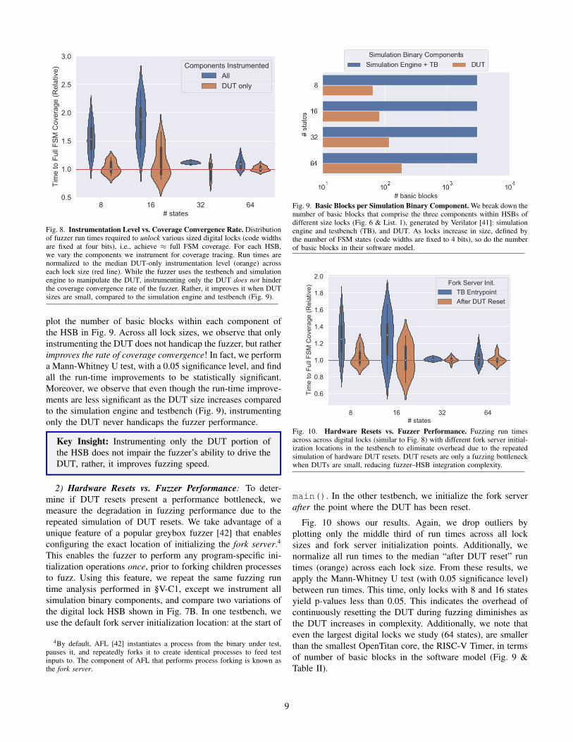
2) Hardware Resets vs. Fuzzer Performance: To deter-mine if DUT resets present a performance bottleneck, wemeasure the degradation in fuzzing performance due to therepeated simulation of DUT resets. We take advantage of aunique feature of a popular greybox fuzzer [42] that enablesconfiguring the exact location of initializing the fork server.4
This enables the fuzzer to perform any program-specific ini-tialization operations once, prior to forking children processesto fuzz. Using this feature, we repeat the same fuzzing runtime analysis performed in §V-C1, except we instrument allsimulation binary components, and compare two variations ofthe digital lock HSB shown in Fig. 7B. In one testbench, weuse the default fork server initialization location: at the start of
4By default, AFL [42] instantiates a process from the binary under test,pauses it, and repeatedly forks it to create identical processes to feed testinputs to. The component of AFL that performs process forking is known asthe fork server.
Fig. 9. Basic Blocks per Simulation Binary Component. We break down thenumber of basic blocks that comprise the three components within HSBs ofdifferent size locks (Fig. 6 & List. 1), generated by Verilator [41]: simulationengine and testbench (TB), and DUT. As locks increase in size, defined bythe number of FSM states (code widths are fixed to 4 bits), so do the numberof basic blocks in their software model.
8 16 32 64# states
0.6
0.8
1.0
1.2
1.4
1.6
1.8
2.0
Tim
e to
Ful
l FS
M C
over
age
(Rel
ativ
e)
Fork Server Init.TB EntrypointAfter DUT Reset
Fig. 10. Hardware Resets vs. Fuzzer Performance. Fuzzing run timesacross across digital locks (similar to Fig. 8) with different fork server initial-ization locations in the testbench to eliminate overhead due to the repeatedsimulation of hardware DUT resets. DUT resets are only a fuzzing bottleneckwhen DUTs are small, reducing fuzzer–HSB integration complexity.
main(). In the other testbench, we initialize the fork serverafter the point where the DUT has been reset.
Fig. 10 shows our results. Again, we drop outliers byplotting only the middle third of run times across all locksizes and fork server initialization points. Additionally, wenormalize all run times to the median “after DUT reset” runtimes (orange) across each lock size. From these results, weapply the Mann-Whitney U test (with 0.05 significance level)between run times. This time, only locks with 8 and 16 statesyield p-values less than 0.05. This indicates the overhead ofcontinuously resetting the DUT during fuzzing diminishes asthe DUT increases in complexity. Additionally, we note thateven the largest digital locks we study (64 states), are smallerthan the smallest OpenTitan core, the RISC-V Timer, in termsof number of basic blocks in the software model (Fig. 9 &Table II).
9

Fig. 11. Hardware Fuzzing vs. CRV. Run times for both Hardware Fuzzing (A) and CRV (B) to achieve ≈ full FSM coverage of various digital lock(Fig. 6) designs—i.e., time to unlock the lock—using the testbench architectures shown in Fig. 7. Run times are averaged across 20 trials for each lockdesign—defined by a (# states, code width) pair—and DV method combination. Across these designs, Hardware Fuzzing achieves full FSM coverage fasterthan traditional CRV approaches, by over two orders of magnitude.
Key Insight: Overhead from simulating hardware resetswhile fuzzing is minimal, especially in large designs,further reducing fuzzer–HSB integration efforts.
D. Hardware Fuzzing vs. CRVUsing the techniques we learned from above, we perform a
run-time comparison analysis between Hardware Fuzzing andCRV,5 the current state-of-the-art hardware dynamic verifica-tion technique. We perform these experiments using digitallocks of various complexities, from 2 to 64 states, and codewidths of 1 to 8 bits. The two HSB architectures we compareare shown in Fig. 7, and discussed in §V-B. Note, the fuzzerwas again seeded with an empty file to align its starting statewith the CRV tests.
Similar to our instrumentation and reset experiments (§V-C)we measure the fuzzing run times required to achieve ≈ fullFSM coverage of each lock design, i.e., the time to unlockeach lock. We illustrate these run times in heatmaps shownin Fig. 11. We perform 20 trials for each experiment andaverage these run times in each square of a heatmap. Whilethe difference between the two approaches is indistinguishablefor extremely small designs, the advantages of HardwareFuzzing become apparent as designs increase in complexity.For medium to larger lock designs, Hardware Fuzzing achievesfull FSM coverage faster than CRV by over two orders-of-magnitude, even when the fuzzer is seeded with an emptyfile. Moreover, many CRV experiments were terminated early(after running for five days) to save money on GCP instances.
Key Insight: Hardware Fuzzing is a low-cost, low-overhead CDG approach for hardware DV.
5CRV is widely deployed in any DV testbenches built around the co-cotb [40] or UVM [27] frameworks, e.g., all OpenTitan [35] IP coretestbenches.
VI. EVALUATION - PART 2
In the second part of our evaluation, we address tworemaining questions. First, how should we format our gram-mar to enable the fuzzer to learn it quickly? To facilitatewidespread deployment of Hardware Fuzzing, it is imperativeDV engineers do not have to tailor fuzzing harnesses (test-benches) to specific designs, as is the case with existing CDGmethods [15], [22], [24], [25], [28]–[30]. Lastly, how doesHardware Fuzzing perform in practice on real hardware IPcores? To address these questions, we perform E2E fuzzinganalyses on four commercial hardware cores from Google’sOpenTitan [35] SoC.
A. OpenTitan IP
The four OpenTitan IP blocks we study are the: AES,HMAC, KMAC, and RISC-V Timer cores. While each coreperforms different functions, they all conform to the OpenTitanComportability Specification [80], which implies they areall controlled via reads and writes to memory-mappedregisters over a TL-UL bus. By adhering to a uniform busprotocol, we are able to re-use a generic fuzzing harness(Fig. 12), facilitating the deployability of our approach. Below,we highlight the functionality of each IP core. Additionally,in Table II, we report the complexity of each IP core in boththe hardware and software domains, in terms of Lines of Code(LOC), number of basic blocks, and number of SVAs providedin each core’s HDL. Software models of each hardware designare produced using Verilator, as we describe in §III-A1.
1) AES: The OpenTitan AES core implements the Ad-vanced Encryption Standard with key sizes of 128, 192,and 256 bits, and with the following cipher block modes:ECB, CBC, CFB, OFB, and CTR. Configuration settings,keys, and plaintext are delivered to the core through TileLinkwrite operations to memory-mapped registers in a documentedaddress range. Likewise, ciphertext is retrieved from the core
10

IP core (DUT)
STDIN Decode
Generic Testbench (C++)
AFL TileLink
Seeds*
cove
rag
e Fetch
TileLink DriverSVAs
TileLink Bus
Provided by OpenTitan Our Design
.hwf
Hard
war
e Si
mul
atio
n Bi
nary
Fig. 12. OpenTitan HSB Architecture. A software fuzzer learns to generatefuzzing instructions (Fig. 4)—from .hwf seed files—based on a hardwarefuzzing grammar (§III-B4). It pipes these instructions to stdin wherea generic C++ fuzzing harness fetches/decodes them, and performs thecorresponding TileLink bus operations to drive the DUT. SVAs are evaluatedduring execution of the HSB, and produce a program crash (if violated), thatis caught and reported by the software fuzzer.
through TileLink read operations. The core targets mediumperformance (one clock cycle per round of encryption). Itimplements a 128-bit wide data path—shared by encryptionand decryption operations—that translates to encryption/de-cryption latencies of 12, 14, and 16 clock cycles per 128-bit plaintext block, in 128, 192, and 256 bit key modes,respectively. Of the cores we study, it is the second mostcomplex in terms of LOC in both the hardware (HDL) andsoftware domains (Table II).
2) HMAC: The OpenTitan HMAC implements a SHA-256hash message authentication code generator for the purposeof checking the integrity of incoming messages. The HMACcore can operate in two modes: 1) SHA-256 mode only, or 2)HMAC mode. In the former mode, the core simply computesthe SHA-256 hash of a provided message. In the latter mode,the core computes the HMAC (defined in RFC 2104 [84]) of amessage using the SHA-256 hashing algorithm and a providedsecret key. Regardless of mode, the SHA-256 engine operateson 512-bit message chunks at any given time, provided tothe core through a message FIFO. Input messages can beread little- or big-endian and likewise, message digests can bestored in output registers either little- or big-endian. Config-uration settings, input messages, HMAC keys, and operationcommands are delivered to the core through TileLink writeoperations to memory-mapped registers. Likewise, messagedigests are retrieved from the core through TileLink readoperations. In its current state, the core can hash a single 512-bit message in 80 clock cycles, and can compute its HMACin 340 clock cycles. Of the cores we study, it is approximatelyhalf as complex as the AES core, in terms of LOC in both thehardware and software domains (Table II).
3) KMAC: The OpenTitan KMAC core is similar tothe HMAC core, except it implements a Keccak MessageAuthentication Code [85] and SHA-3 hashing algorithms.However, compared to the HMAC core, the KMAC coreis more complex, as there are several more configurations.
TABLE IIOPENTITAN IP CORE COMPLEXITY IN HW AND SW DOMAINS.
IP Core HW LOC SW LOC # Basic Blocks* # SVAs†AES 4,562 38,036 3,414 53HMAC 2,695 18,005 1,764 30KMAC 4,585 119,297 6,996 44RV Timer 677 3,111 290 8
* # of basic blocks in compiled software model with O3 optimization.† # of SystemVerilog Assertions included in IP HDL at time of writing.
Specifically, there are many SHA-3 hashing functions thatare supported—SHA3-224/256/384/512, SHAKE128/256, andcSHAKE128/256—and the Keccak− f function (by default)operates on 1600 bits of internal state. Like the HMACcore, the KMAC core can simply compute hashes or messageauthentication codes depending on operation mode, and inputmessages/output digests can be configured to be read/storedin little- or big-endian. The time to process a single inputmessage block is dominated by computing the Keccak − ffunction, which takes 72 clock cycles for 1600 bits of internalstate, in the current implementation of the core. Configurationsettings, input messages, output digests, keys, and operationcommands are all communicated to/from the core throughTileLink writes/reads to memory-mapped registers.
Of the cores we study, the KMAC core is the most complex,especially in the software domain (Table II). The softwaremodel of the KMAC core contains almost 120k lines of C++code. This is mostly an artifact of how Verilator maps depen-dencies between large registers and vectored signals: it createslarge multidimensional arrays and maps each correspondingindex at the word granularity. Fortunately, this artifact isoptimized away during compilation, and the number of basicblocks in the DUT portion of the HSB is reduced.
4) RV-Timer: The OpenTitan RISC-V timer core is thesimplest core we fuzz. It consists of a single 64-bit timer with12-bit prescaler and an 8-bit step configurations. It can alsogenerate system interrupts upon reaching a pre-configured timevalue. Like the other OpenTitan cores, the RV-Timer core isconfigured, activated, and deactivated via TileLink writes tomemory-mapped registers.
B. Optimizing the Hardware Fuzzing Grammar
Recall, to facilitate widespread adoption of HardwareFuzzing we design a generic testbench fuzzing harness thatdecodes a grammar and performs corresponding TL-UL bustransactions to exercise the DUT (Fig. 12). However, thereare implementation questions surrounding how the grammarshould be decoded (§III-B4):
1) How should we decode 8-bit opcodes when the opcodespace defines less than 28 valid testbench actions?
2) How should we pack Hardware Fuzzing instructionframes that conform to our grammar?
1) Opcode Formats: In its current state, we define threeopcodes in our grammar that correspond to three actions ourgeneric testbench can perform (Table I): 1) wait one clock cy-cle, 2) TL-UL read, and 3) TL-UL write. However, we chose
11

89
90
91C
ov. (
%)
aes | SW Line (kcov)
86
88
Cov
. (%
)
hmac | SW Line (kcov)
94
95
96
Cov
. (%
)
kmac | SW Line (kcov)
85
90
Cov
. (%
)
rv_timer | SW Line (kcov)
58
60
62
Cov
. (%
)
aes | SW Basic Block (LLVM)
64
66
68
Cov
. (%
)
hmac | SW Basic Block (LLVM)
68
70
Cov
. (%
)
kmac | SW Basic Block (LLVM)
65
70
Cov
. (%
)
rv_timer | SW Basic Block (LLVM)
0 10 20Time (hours)
85
90
Cov
. (%
)
aes | HW Line (VLT)
0 10 20Time (hours)
60
80C
ov. (
%)
hmac | HW Line (VLT)
0 10 20Time (hours)
60
80
Cov
. (%
)
kmac | HW Line (VLT)
0.000 0.025 0.050 0.075 0.100Time (hours)
25
50
75
Cov
. (%
)
rv_timer | HW Line (VLT)
Grammar (Opcode Format | Frame Format)Constant | Variable Constant | Fixed Mapped | Variable Mapped | Fixed
Fig. 13. Coverage Convergence vs. Hardware Fuzzing Grammar. Various software and hardware coverage metrics over fuzzing time across fourOpenTitan [35] IP cores and hardware fuzzing grammar variations (§VI-B). In the first row, we plot line coverage of the software models of each hardwarecore computed using kcov. In the second row, we plot basic block coverage computed using LLVM. In last row, we plot HDL line coverage (of the hardwareitself) computed using Verilator [41]. From these results we formulate two conclusions: 1) coverage in the software domain correlates to coverage in thehardware domain, and 2) the Hardware Fuzzing grammar with variable instruction frames is best for greybox fuzzers that prioritize small test files.
to represent these opcodes with a single byte (Fig. 4). Choos-ing a larger field than necessary has implications regardingthe fuzzability of our grammar. In its current state, 253 of the256 possible opcode values may be useless depending on howthey are decoded by the testbench. Therefore we propose, andempirically study, two design choices for decoding HardwareFuzzing opcodes into testbench actions:
• Constant: constant values are used to represent each op-code corresponding to a single testbench action. Remain-ing opcode values are decoded as invalid, and ignored.
• Mapped: equal sized ranges of opcode values are mappedto valid testbench actions. No invalid opcode values exist.
2) Instruction Frame Formats: Of the three actions ourtestbench can perform—wait, read, and write—some requireadditional information. Namely, the TL-UL read action re-quires a 32-bit address field, and the TL-UL write actionrequires 32-bit data and address fields. Given this, there aretwo natural ways to decode Hardware Fuzzing instructions(Fig. 4):
• Fixed: a fixed instruction frame size is decoded regardlessof the opcode. Address and data fields could go unuseddepending on the opcode.
• Variable: a variable instruction frame size is decoded.Address and data fields are only appended to opcodes thatcorrespond to TL-UL read and write testbench actions.No address/data information goes unused.
3) Results: To determine the optimal Hardware Fuzzinggrammar, we fuzz four OpenTitan IP blocks—the AES,HMAC, KMAC, and RV-Timer—for 24 hours using all com-binations of opcode and instruction frame formats mentionedabove. For each core we seed the fuzzer with 8–12 binaryHardware Fuzzing seed files (in the corresponding HardwareFuzzing grammar) that correctly drive each core, with the
exception of the RV-Timer core, which we seed with a singlewait operation instruction due to its simplicity. For eachexperiment, we extract and plot three DUT coverage metricsover fuzz times in Fig. 13. These metrics include: 1) linecoverage of the DUT software model, 2) basic block coverageof the same, and 3) line coverage of the DUT’s HDL. Softwareline coverage is computed using kcov [86], software basicblock coverage is computed using LLVM [87], and hardwareline coverage is computed using Verilator [41]. Since weperform 10 repetitions of each fuzzing experiment, we averageand consolidate each coverage time series into a single trace.
From these results we draw two conclusions. First, vari-able instruction frames seem to perform better than fixedframes, especially early in the fuzzing exploration. SinceAFL prioritizes keeping test files small, we expect variablesized instruction frames to produce better results, since thistranslates to longer hardware test sequences, and thereforedeeper possible explorations of the (sequential) state space.Second, the opcode type seems to make little difference, formost experiments, since there are only 256 possible values, asearch space AFL can explore very quickly. Lastly, we pointout that for simple cores, like the RV-Timer, Hardware Fuzzingis able to achieve ≈85% HDL line coverage in less than aminute (hence we do not plot the full 24-hour trace).
Key Insights:1) Hardware Fuzzing instructions with variable
frames are optimal for fuzzers that prioritize smallinput files, therefore resulting in longer temporaltest sequences.
2) Increasing coverage in the software domain, trans-lates to the hardware domain.
12

0 10 20 30 40 50 60Time (min.)
0
20
40
60
80H
DL
Line
Cov
. (%
)
Coreaeshmac
kmacrv_timer
Fig. 14. Coverage vs. Time Fuzzing with Empty Seeds. Fuzzing fourOpenTitan [35] IP cores for one hour, seeding the fuzzer with an empty filein each case, yields over 88% HDL line coverage in three out of four designs.
C. Hardware Fuzzing in Practice
Finally, we address the question: How does HardwareFuzzing perform in practice? First, we show that with noknowledge of how to properly use the DUT, we achieve almost90% HDL line coverage across the OpenTitan [35] cores westudy. Second, we compare Hardware Fuzzing against the mostpopular DV technique today, CRV, demonstrating over twoorders-of-magnitude faster coverage-convergence times.
Unlike most software applications that are fuzzed [34], weobserve that software models of hardware are quite small (Ta-ble II). So, we decided to experiment fuzzing each OpenTitancore we study for one hour, using a single empty seed file asstarting input. We plot the results of this experiment in Fig. 14.After only one hour of fuzzing with no proper starting seeds,we achieve over 88% HDL line coverage across three of thefour OpenTitan IP cores we study, and over 65% coverage ofthe remaining design.
VII. DISCUSSION
1) Detecting Bugs During Fuzzing: The focus of Hard-ware Fuzzing is to provide a scalable yet flexible solutionfor integrating CDG with hardware simulation. However, testgeneration and hardware simulation comprise only two-thirdsof the hardware verification process (§II-A). The final, andarguably most important, step is detecting incorrect hardwarebehavior, i.e., test evaluation in §II-A3. For this there are twoapproaches: 1) invariant checking and 2) (gold) model check-ing. In both cases, we trigger HSB crashes upon detectingincorrect hardware behavior, which software fuzzers log. Forinvariant checks, we use SVAs that send the HSB process theSIGABRT signal upon assertion violation. Likewise, for goldmodel checking testbenches any mismatches between modelsresults in a SIGABRT.
2) Additional Bus Protocols: To provide a design-agnosticinterface to fuzz RTL hardware, we develop a design-agnostictestbench harness (Fig. 12). Our harness decodes fuzzer-generated tests using a bus-specific grammar (§III-B4), andproduces corresponding TL-UL bus transactions that drive aDUT. In our current implementation, our generic testbenchharness conforms to the TL-UL bus protocol [82]. As a result,we can fuzz any IP core that speaks the same bus protocol(e.g., all OpenTitan cores [35]). To fuzz cores that speak other
bus protocols (e.g., Wishbone, AMBA, Avalon, etc.), users cansimply write a new harness for the bus they wish to support.
3) Hardware without a Bus Interface: For hardware coresthat perform I/O over a generic set of ports that do notconform to any bus protocol, we provide a generic testbenchharness that maps fuzzer-generated input files across spatialand temporal domains by interpreting each fuzzer-generatedfile as a sequence of DUT inputs (Algo. 1). We demonstratethis Hardware Fuzzing configuration when fuzzing variousdigital locks (Fig. 7B). However, if inputs require any struc-tural dependencies, we advise developing a grammar andcorresponding testbench—similar to our bus-specific grammar(§III-B4)—to aid the fuzzer in generating valid test cases.Designers can use the lessons in this paper to guide their core-specific grammar designs.
4) Limitations: While Hardware Fuzzing is both efficientand design-agnostic, there are some limitations. First, unlikesoftware there is no notion of a hardware sanitizer, that canadd safeguards against generic classes of hardware bugs forthe fuzzer to sniff out. While we envision hardware sanitizersbeing a future active research area, for now, DV engineersmust create invariants or gold models to check design behavioragainst for the fuzzer to find crashing inputs. Second, there isnotion of analog behavior in RTL hardware, let along in trans-lated software models. In its current implementation, HardwareFuzzing is not effective against detecting side-channel vulner-abilities that rely on information transmission/leakage throughanalog domains.
VIII. RELATED WORK
There are two categories of prior CDG approaches: 1)design-agnostic and 2) design-specific.
1) Design-Agnostic: Laeufer et al. ’s RFUZZ [15] is themost relevant prior work, which attempts to build a full-fledged design-agnostic RTL fuzzer. To achieve their goal,they propose a new RTL coverage metric—mux toggle cover-age—that measures if the control signal to a 2:1 multiplexerexpresses both states (0 and 1). Unlike Hardware Fuzzing,they instrument the HDL directly, and develop their owncustom RTL fuzzer (Fig. 1). Unfortunately, RFUZZ must beaccelerated on FPGAs since coverage tracing is slow, and it isunclear how their mux toggle coverage maps to existing RTLcoverage metrics DV engineers care about most, e.g., codecoverage and functional coverage [37], [38]. Gent et al. [17]propose an automatic test pattern generator based on customcoverage metrics, for which they also instrument the RTLdirectly to trace. Unfortunately, like RFUZZ, the scalabilityof their approach remains in question, given their coveragetracing method, and unlike RFUZZ, they do not accelerate theirsimulations on FPGAs.
2) Design-Specific: Unlike the design-agnosticapproaches, the following work proposes CDG techniquesexclusively for processors. Zhang et al. propose Coppelia [32],a tool that uses a custom symbolic execution engine (builton top of KLEE [70]) on software models of the RTL.Coppelia’s goal is to target specific security-critical properties
13

of processors; Hardware Fuzzing enables combining suchstatic methods with fuzzing (i.e., concolic execution [69])for free, overcoming the limits of symbolic executionalone. Two other processor-specific CDG approaches areSquillero’s MicroGP [16] and Bose et al. ’s [18] thatuse a genetic algorithms to generate random assemblyprograms that maximize RTL code coverage of a processor.Unlike Hardware Fuzzing, these approaches require customDUT-specific grammars to build assembly programs from.
IX. CONCLUSION
Hardware Fuzzing is an effective solution to CDG forhardware DV. Unlike prior work, we take advantage of featurerich software testing methodologies and tools, to solve a long-standing problem in hardware DV. To make our approach at-tractive to DV practitioners, we solve several key deployabilitychallenges, including developing generic interfaces (grammar& testbench) to fuzz RTL in a design- agnostic manner.Using our generic grammar and testbench, we demonstratehow Hardware Fuzzing can achieve over 88% HDL codecoverage of three out of four commercial-grade hardwaredesigns in only one hour, with no knowledge of the DUTdesign or implementation. Moreover, compared to standarddynamic verification practices, we achieve over two order-of-magnitude faster design coverage with Hardware Fuzzing.
ACKNOWLEDGMENT
We thank Scott Johnson, Srikrishna Iyer, Rupert Swarbrick,Pirmin Vogel, Philipp Wagner, and other members of theOpenTitan team for their technical expertise that enabled usto demonstrate our approach on the OpenTitan IP ecosystem.
REFERENCES
[1] G. E. Moore, “Cramming more components onto integrated circuits,”1965.
[2] R. H. Dennard, F. H. Gaensslen, V. L. Rideout, E. Bassous, and A. R.LeBlanc, “Design of ion-implanted mosfet’s with very small physicaldimensions,” IEEE Journal of Solid-State Circuits, 1974.
[3] T. Chen, Z. Du, N. Sun, J. Wang, C. Wu, Y. Chen, and O. Temam,“Diannao: A small-footprint high-throughput accelerator for ubiquitousmachine-learning,” ACM SIGARCH Conference on Architectural Sup-port for Programming Languages and Operating Systems (ASPLOS),2014.
[4] T. Nowatzki, V. Gangadhan, K. Sankaralingam, and G. Wright, “Pushingthe limits of accelerator efficiency while retaining programmability,”in IEEE International Symposium on High Performance ComputerArchitecture (HPCA), 2016.
[5] N. Jouppi, C. Young, N. Patil, and D. Patterson, “Motivation for andevaluation of the first tensor processing unit,” IEEE Micro, 2018.
[6] R. Hameed, W. Qadeer, M. Wachs, O. Azizi, A. Solomatnikov, B. C.Lee, S. Richardson, C. Kozyrakis, and M. Horowitz, “Understandingsources of inefficiency in general-purpose chips,” in the 37th annualInternational Symposium on Computer Architecture (ISCA), 2010.
[7] I. Magaki, M. Khazraee, L. V. Gutierrez, and M. B. Taylor, “ASICclouds: Specializing the datacenter,” in 2016 ACM/IEEE 43rd AnnualInternational Symposium on Computer Architecture (ISCA). IEEE,2016, pp. 178–190.
[8] S. Shao and E. Wang, “Die photo analysis,” http://vlsiarch.eecs.harvard.edu/research/accelerators/die-photo-analysis/.
[9] M. Corporation, “Cve details: Intel: Vulnerability statistics,” August2019, https://www.cvedetails.com/vendor/238/Intel.html.
[10] P. Kocher, J. Horn, A. Fogh, , D. Genkin, D. Gruss, W. Haas,M. Hamburg, M. Lipp, S. Mangard, T. Prescher, M. Schwarz, andY. Yarom, “Spectre attacks: Exploiting speculative execution,” in 40thIEEE Symposium on Security and Privacy (S&P’19), 2019.
[11] M. Lipp, M. Schwarz, D. Gruss, T. Prescher, W. Haas, A. Fogh,J. Horn, S. Mangard, P. Kocher, D. Genkin, Y. Yarom, and M. Hamburg,“Meltdown: Reading kernel memory from user space,” in 27th USENIXSecurity Symposium (USENIX Security’18), 2018.
[12] J. Van Bulck, M. Minkin, O. Weisse, D. Genkin, B. Kasikci, F. Piessens,M. Silberstein, T. F. Wenisch, Y. Yarom, and R. Strackx, “Foreshadow:Extracting the keys to the Intel SGX kingdom with transient out-of-orderexecution,” in 27th USENIX Security Symposium (USENIX Security’18),2018.
[13] S. van Schaik, A. Milburn, S. Osterlund, P. Frigo, G. Maisuradze,K. Razavi, H. Bos, and C. Giuffrida, “RIDL: Rogue in-flight data load,”in 40th IEEE Symposium on Security and Privacy (S&P’19), 2019.
[14] C. Canella, D. Genkin, L. Giner, D. Gruss, M. Lipp, M. Minkin,D. Moghimi, F. Piessens, M. Schwarz, B. Sunar, J. Van Bulck, andY. Yarom, “Fallout: Leaking data on meltdown-resistant CPUs,” in ACMSIGSAC Conference on Computer and Communications Security (CCS),2019.
[15] K. Laeufer, J. Koenig, D. Kim, J. Bachrach, and K. Sen, “RFUZZ:coverage-directed fuzz testing of RTL on FPGAs,” in IEEE/ACM In-ternational Conference on Computer-Aided Design (ICCAD). IEEE,2018.
[16] G. Squillero, “Microgp—an evolutionary assembly program generator,”Genetic Programming and Evolvable Machines, 2005.
[17] K. Gent and M. S. Hsiao, “Fast multi-level test generation at the rtl,”in 2016 IEEE Computer Society Annual Symposium on VLSI (ISVLSI),2016.
[18] M. Bose, J. Shin, E. M. Rudnick, T. Dukes, and M. Abadir, “A geneticapproach to automatic bias generation for biased random instruction gen-eration,” in Proceedings of the Congress on Evolutionary Computation.IEEE, 2001.
[19] T. Kim, “Intel’s alleged security flaw could cost chipmaker a lot ofmoney, Bernstein says,” https://www.cnbc.com/2018/01/03/intels-alleged-security-flaw-could-cost-chipmaker-a-lot-of-money-bernstein.html.
[20] K. Yang, M. Hicks, Q. Dong, T. Austin, and D. Sylvester, “A2: Analogmalicious hardware,” in IEEE Symposium on Security and Privacy (SP),2016.
[21] L.-T. Wang, Y.-W. Chang, and K.-T. T. Cheng, Electronic designautomation: synthesis, verification, and test. Morgan Kaufmann, 2009.
[22] S. Fine and A. Ziv, “Coverage directed test generation for functionalverification using bayesian networks,” in the 40th annual Design Au-tomation Conference (DAC), 2003.
[23] D. Moghimi, B. Sunar, T. Eisenbarth, and N. Heninger, “TPM-FAIL:TPM meets Timing and Lattice Attacks,” in 29th USENIX SecuritySymposium (USENIX Security’20), 2020. [Online]. Available: https://www.usenix.org/conference/usenixsecurity20/presentation/moghimi
[24] M. Cieplucha, “Metric-driven verification methodology with regressionmanagement,” Journal of Electronic Testing, 2019.
[25] C. Ioannides, G. Barrett, and K. Eder, “Introducing xcs to coveragedirected test generation,” in IEEE International High Level DesignValidation and Test Workshop (HLDVT), 2011.
[26] J. Yuan, C. Pixley, A. Aziz, and K. Albin, “A framework for constrainedfunctional verification,” in International Conference on Computer AidedDesign (ICCAD). IEEE, 2003.
[27] Accellera, “Universal Verification Methodology (UVM),” https://www.accellera.org/downloads/standards/uvm.
[28] M. Teplitsky, A. Metodi, and R. Azaria, “Coverage driven distributionof constrained random stimuli,” in Proceedings of the Design andVerification Conference (DVCon), 2015.
[29] O. Guzey and L.-C. Wang, “Coverage-directed test generation throughautomatic constraint extraction,” in IEEE International High LevelDesign Validation and Test Workshop (HLDVT), 2007.
[30] F. Wang, H. Zhu, P. Popli, Y. Xiao, P. Bodgan, and S. Nazarian, “Ac-celerating coverage directed test generation for functional verification:A neural network-based framework,” in Proceedings of the Great LakesSymposium on VLSI, 2018.
[31] R. Zhang and C. Sturton, “A recursive strategy for symbolic executionto find exploits in hardware designs,” in ACM SIGPLAN InternationalWorkshop on Formal Methods and Security (FSM), 2018.
14

[32] R. Zhang, C. Deutschbein, P. Huang, and C. Sturton, “End-to-endautomated exploit generation for validating the security of processordesigns,” in 51st Annual IEEE/ACM International Symposium on Mi-croarchitecture (MICRO). IEEE, 2018.
[33] T. Trippel, “Hardware Fuzzing Pipeline,” https://github.com/googleinterns/hw-fuzzing.
[34] K. Serebryany, “OSS-Fuzz - google’s continuous fuzzing service foropen source software,” in USENIX Security Symposium, 2017.
[35] lowRISC, “Opentitan,” https://opentitan.org/.[36] R. Kaivola, R. Ghughal, N. Narasimhan, A. Telfer, J. Whittemore,
S. Pandav, A. Slobodova, C. Taylor, V. Frolov, E. Reeber et al.,“Replacing testing with formal verification in intel core i7 processorexecution engine validation,” in International Conference on ComputerAided Verification (CAV). Springer, 2009.
[37] S. Tasiran and K. Keutzer, “Coverage metrics for functional validationof hardware designs,” IEEE Design & Test of Computers, 2001.
[38] J.-Y. Jou and C.-N. J. Liu, “Coverage analysis techniques for hdl designvalidation,” Proceedings of Asia Pacific CHip Design Languages, 1999.
[39] A. Piziali, Functional verification coverage measurement and analysis.Springer Science & Business Media, 2007.
[40] P. Ventures, “cocotb,” https://github.com/cocotb/cocotb.[41] W. Snyder, “verilator,” https://www.veripool.org/wiki/verilator.[42] M. Zalewski, “American fuzzy lop,” https://lcamtuf.coredump.cx/afl/.[43] LLVM Project, “libFuzzer – a library for coverage-guided fuzz testing,”
https://llvm.org/docs/LibFuzzer.html.[44] R. Swiecki, “honggfuzz,” https://honggfuzz.dev/.[45] Synopsys, “VCS,” https://www.synopsys.com/verification/simulation/
vcs.html.[46] Mentor Graphics, “ModelSim,” https://www.mentor.com/products/fv/
modelsim/.[47] Cadence Design Systems, “Xcelium Logic Simulation,”
https://www.cadence.com/en\ US/home/tools/system-design-and-verification/simulation-and-testbench-verification/xcelium-simulator.html.
[48] S. Williams, “Icarus Verilog,” http://iverilog.icarus.com/.[49] M. Sutton, A. Greene, and P. Amini, Fuzzing: brute force vulnerability
discovery. Pearson Education, 2007.[50] E. Bounimova, P. Godefroid, and D. Molnar, “Billions and billions
of constraints: Whitebox fuzz testing in production,” in 2013 35thInternational Conference on Software Engineering (ICSE). IEEE, 2013.
[51] S. Nagy and M. Hicks, “Full-speed fuzzing: Reducing fuzzing overheadthrough coverage-guided tracing,” in Symposium on Security and Privacy(S&P). IEEE, 2019.
[52] Mozilla Security, “Dharma: A generation-based, context-free grammarfuzzer,” https://www.overleaf.com/project/5e163844e63c070001079faa.
[53] J. Johnson, “gramfuzz,” https://github.com/d0c-s4vage/gramfuzz.[54] C. Aschermann, T. Frassetto, T. Holz, P. Jauernig, A.-R. Sadeghi, and
D. Teuchert, “NAUTILUS: Fishing for deep bugs with grammars.” inNetwork and Distributed Systems Security Symposium (NDSS), 2019.
[55] Peach Tech, “Peach Fuzzing Platform,” https://www.peach.tech/products/peach-fuzzer/.
[56] J. Wang, B. Chen, L. Wei, and Y. Liu, “Skyfire: Data-driven seedgeneration for fuzzing,” in IEEE Symposium on Security and Privacy(S&P), 2017.
[57] ——, “Superion: Grammar-aware greybox fuzzing,” in IEEE/ACM In-ternational Conference on Software Engineering (ICSE), 2019.
[58] M. Bohme, V.-T. Pham, and A. Roychoudhury, “Coverage-based grey-box fuzzing as markov chain,” IEEE Transactions on Software Engi-neering, 2017.
[59] P. Zong, T. Lv, D. Wang, Z. Deng, R. Liang, and K. Chen, “FuzzGuard:Filtering out unreachable inputs in directed grey-box fuzzing throughdeep learning,” in USENIX Security Symposium, 2020.
[60] H. Chen, Y. Xue, Y. Li, B. Chen, X. Xie, X. Wu, and Y. Liu, “Hawkeye:Towards a desired directed grey-box fuzzer,” in ACM SIGSAC Confer-ence on Computer and Communications Security (CCS), 2018.
[61] C. Aschermann, S. Schumilo, A. Abbasi, and T. Holz, “Ijon: Exploringdeep state spaces via fuzzing,” in IEEE Symposium on Security andPrivacy (S&P), 2020.
[62] S. Osterlund, K. Razavi, H. Bos, and C. Giuffrida, “ParmeSan: Sanitizer-guided greybox fuzzing,” in USENIX Security Symposium, 2020.
[63] W. You, P. Zong, K. Chen, X. Wang, X. Liao, P. Bian, and B. Liang,“Semfuzz: Semantics-based automatic generation of proof-of-conceptexploits,” in ACM SIGSAC Conference on Computer and Communica-tions Security (CCS), 2017.
[64] T. Wang, T. Wei, G. Gu, and W. Zou, “TaintScope: A checksum-awaredirected fuzzing tool for automatic software vulnerability detection,” inIEEE Symposium on Security and Privacy (S&P), 2010.
[65] K. Serebryany, “Continuous fuzzing with libfuzzer and addresssanitizer,”in Cybersecurity Development (SecDev). IEEE, 2016.
[66] D. Vyukov, “syzkaller,” https://github.com/google/syzkaller.[67] S. Rawat, V. Jain, A. Kumar, L. Cojocar, C. Giuffrida, and H. Bos,
“VUzzer: Application-aware evolutionary fuzzing,” in Network andDistributed Systems Security Symposium (NDSS), 2017.
[68] M. Vuagnoux, “Autodaf´e: an act of software torture,” http://autodafe.sourceforge.net/tutorial/index.html.
[69] N. Stephens, J. Grosen, C. Salls, A. Dutcher, R. Wang, J. Corbetta,Y. Shoshitaishvili, C. Kruegel, and G. Vigna, “Driller: Augmentingfuzzing through selective symbolic execution.” in Network and Dis-tributed Systems Security Symposium (NDSS), 2016.
[70] C. Cadar, D. Dunbar, D. R. Engler et al., “KLEE: Unassisted andautomatic generation of high-coverage tests for complex systems pro-grams.” in USENIX Symposium on Operating Systems Design andImplementation (OSDI), 2008.
[71] S. K. Cha, T. Avgerinos, A. Rebert, and D. Brumley, “Unleashingmayhem on binary code,” in IEEE Symposium on Security and Privacy(S&P), 2012.
[72] H. Huang, P. Yao, R. Wu, Q. Shi, and C. Zhang, “PANGOLIN:Incremental hybrid fuzzing with polyhedral path abstraction,” in IEEESymposium on Security and Privacy (S&P), 2020.
[73] I. Yun, S. Lee, M. Xu, Y. Jang, and T. Kim, “{QSYM}: A practicalconcolic execution engine tailored for hybrid fuzzing,” in {USENIX}Security Symposium, 2018.
[74] V. Chipounov, V. Kuznetsov, and G. Candea, “S2E: A platform for in-vivo multi-path analysis of software systems,” ACM SIGPLAN Interna-tional Conference on Architectural Support for Programming Languagesand Operating Systems (ASPLOS), 2011.
[75] P. Godefroid, M. Y. Levin, and D. Molnar, “SAGE: whitebox fuzzingfor security testing,” Queue, 2012.
[76] H. Peng, Y. Shoshitaishvili, and M. Payer, “T-fuzz: fuzzing by programtransformation,” in IEEE Symposium on Security and Privacy (S&P),2018.
[77] J. Hertz and T. Newsham, “ProjectTriforce: AFL/QEMU fuzzing withfull-system emulation,” https://github.com/nccgroup/TriforceAFL.
[78] V. Paxson, W. Estes, and J. Millaway, “Lexical analysis with flex,”University of California, 2007.
[79] The GNU Project, “Bison,” https://www.gnu.org/software/bison/.[80] l. Contributors, “OpenTitan: Comportability Definition and
Specification,” November 2020, https://docs.opentitan.org/doc/rm/comportability specification/.
[81] M. Zalewski, “afl-fuzz: making up grammar with a dictio-nary in hand,” https://lcamtuf.blogspot.com/2015/01/afl-fuzz-making-up-grammar-with.html.
[82] S. Inc., “SiFive: TileLink Specification,” November 2020, version 1.8.0.[83] J. Taylor, “Kaze: an HDL embedded in Rust,” November 2020, https:
//docs.rs/kaze/0.1.13/kaze/.[84] H. Krawczyk, M. Bellare, and M. Bellare, “HMAC: Keyed-hashing
for message authentication,” RFC Editor, RFC 2104, February 1997.[Online]. Available: \url{https://www.rfc-editor.org/rfc/rfc2104.txt}
[85] J. Kelsey, S.-j. Chang, and R. Perlner, “SHA-3 derived functions:cSHAKE, KMAC, TupleHash, and ParallelHash,” National Institute ofStandards and Technology, Tech. Rep., 2016.
[86] S. Kagstrom, “kcov,” https://github.com/SimonKagstrom/kcov.[87] C. Lattner and V. Adve, “LLVM: A compilation framework for lifelong
program analysis and transformation,” in International Symposium onCode Generation and Optimization (CGO), San Jose, CA, USA, 2004.
15