
Future Technology Devices International Ltd Datasheet · Future Technology Devices International...
15
Use of FTDI devices in life support and/or safety applications is entirely at the user’s risk, and the user agrees to defend, indemnify and hold harmless FTDI from any and all damages, claims, suits or expense resulting from such use. FT121 G Sensor Shield Version 1.0 Document Reference No.: FT_000916 Clearance No.: FTDI# 351 Future Technology Devices International Ltd Datasheet FT121 G Sensor Shield 1 Introduction The FT121 G-Sensor shield is designed to connect directly to an Arduino Pro development board. The shield allows the micro-controller on the Arduino Pro to access the FT121 USB device controller. Using the FTDI FT121 chipset and a three axes linear accelerometer (ST LIS331DLH) device, the module may be used to implement a USB HID game controller. The user may also define other interesting applications from the micro-controller board. The Arduino Pro is a micro-controller board based on the ATmega168 or ATmega328 and is not available from FTDI. 1.1 Features The FT121 G Sensor Shield has the following features: FT121 enhanced USB device controller with SPI interface. LIS313DLH 3- axis linear accelerometer (X, Y & Z) with selectable full scales of ±2g/±4g/±8g An SPI Interface: Data transfer over the SPI bus to the Arduino pro via pin headers Selectable SPI & I²C interface to control the 3- axes accelerometer A serial UART output pin Two accelerometer interrupts Three pushbuttons and two LEDs for HID application 5V USB cable power supplied operation Onboard 3.3V regulator to power the accelerometer Mini-B USB connector Operating Temperature range -40 o C to +85 o C
-
Upload
duongthien -
Category
Documents
-
view
224 -
download
1
Transcript of Future Technology Devices International Ltd Datasheet · Future Technology Devices International...

Use of FTDI devices in life support and/or safety applications is entirely at the user’s risk, and the user agrees to defend, indemnify and hold harmless FTDI from any and all damages, claims, suits or expense resulting
from such use.
FT121 G Sensor Shield Version 1.0
Document Reference No.: FT_000916 Clearance No.: FTDI# 351
Future Technology Devices International
Ltd
Datasheet
FT121 G Sensor Shield
1 Introduction
The FT121 G-Sensor shield is designed to connect directly to an Arduino Pro development board. The shield allows the micro-controller on the Arduino Pro to access the FT121 USB device controller. Using the FTDI FT121 chipset and a three axes linear accelerometer (ST LIS331DLH) device, the module
may be used to implement a USB HID game
controller. The user may also define other interesting applications from the micro-controller board.
The Arduino Pro is a micro-controller board based on the ATmega168 or ATmega328 and is not available from FTDI.
1.1 Features
The FT121 G Sensor Shield has the following features:
FT121 enhanced USB device controller with SPI interface.
LIS313DLH 3- axis linear accelerometer (X, Y &
Z) with selectable full scales of ±2g/±4g/±8g
An SPI Interface: Data transfer over the SPI bus to the Arduino pro via pin headers
Selectable SPI & I²C interface to control the 3-axes accelerometer
A serial UART output pin
Two accelerometer interrupts
Three pushbuttons and two LEDs for HID application
5V USB cable power supplied operation
Onboard 3.3V regulator to power the
accelerometer
Mini-B USB connector
Operating Temperature range -40oC to +85oC

2
Copyright © 2013 Future Technology Devices International Limited
FT121 G Sensor Shield Version 1.0
Document Reference No.: FT_000916 Clearance No.: FTDI# 351
2 Typical Applications
The module may be used with the Arduino Pro for:
USB HID controller
USB Game controllers
3 Ordering Information
The module is sold as individual units as below:
Part No. Description
VSHLD-FT121 FT121 G-Sensor Shield Board
Table 3-1 – Ordering information
3
Copyright © 2013 Future Technology Devices International Limited
FT121 G Sensor Shield Version 1.0
Document Reference No.: FT_000916 Clearance No.: FTDI# 351
Table of Contents
1 Introduction ................................................................................... 1
1.1 Features ........................................................................................................ 1
2 Typical Applications ........................................................................ 2
3 Ordering Information ..................................................................... 2
4 Pin Out and Signal Description ....................................................... 4
4.1 Shield Board Connector Description .............................................................. 4
4.2 Shield Board Connector : Pin and Signal Description ..................................... 5
5 Hardware Functionality .................................................................. 7
5.1 Power ............................................................................................................ 7
5.2 Input/Output ................................................................................................ 7
5.3 LEDS.............................................................................................................. 7
5.4 Pushbutton ................................................................................................... 7
5.5 Switches ....................................................................................................... 7
5.6 USB Controller Operation .............................................................................. 8
5.7 Accelerometer Operation .............................................................................. 9
6 Schematic ..................................................................................... 10
7 Mechanical Details ........................................................................ 11
8 Contact Information ..................................................................... 12
Appendix A - References ....................................................................................... 23
Appendix B - List of Figures and Tables ................................................................. 24
Appendix C – Revision History ............................................................................... 25
4
Copyright © 2013 Future Technology Devices International Limited
FT121 G Sensor Shield Version 1.0
Document Reference No.: FT_000916 Clearance No.: FTDI# 351
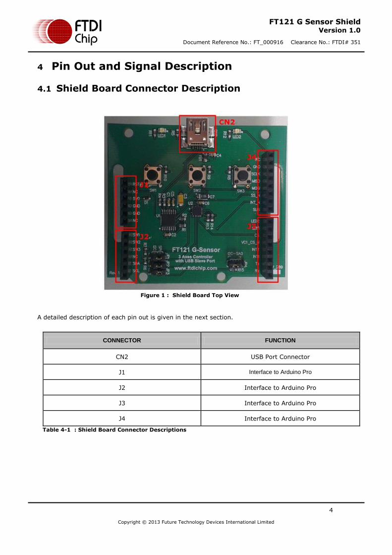
4 Pin Out and Signal Description
4.1 Shield Board Connector Description
Figure 1 : Shield Board Top View
A detailed description of each pin out is given in the next section.
CONNECTOR FUNCTION
CN2 USB Port Connector
J1 Interface to Arduino Pro
J2 Interface to Arduino Pro
J3 Interface to Arduino Pro
J4 Interface to Arduino Pro
Table 4-1 : Shield Board Connector Descriptions

5
Copyright © 2013 Future Technology Devices International Limited
FT121 G Sensor Shield Version 1.0
Document Reference No.: FT_000916 Clearance No.: FTDI# 351
4.2 Shield Board Connector : Pin and Signal Description
Pin No. Name Type Description
J1-1 RESET I Reset for FT121
J1-2 NC - No Connection
J1-3 VCC5V P 5V VBUS Power from USB connector
J1-4 GND P Ground
J1-5 GND P Ground
J1-6 NC - No Connection
J2-1 SW1 O Push button. Logic 0 output when pressed.
J2-2 SW2 O Push button. Logic 0 output when pressed.
J2-3 SW3 O Push button. Logic 0 output when pressed.
J2-4 NC - No Connection
J2-5 SDA I/O I2C Data
J2-6 SCL I I2C Clock
J3-1 RX I UART Data Receiver via the Arduino
J3-2 TX O UART Data Transmitter via the Arduino
J3-3 INT1 O LIS331DLH Interrupt 1
J3-4 INT2 O LIS331DLH Interrupt 2
J3-5 VC1_CS_N I Reserve for VC1 Use
J3-6 CS I LIS331DLH SPI slave select input
J3-7 LED1
I Blue LED. Active low to illuminate. Function defined by
external controller
J3-8 LED2
I Blue LED. Active low to illuminate. Function defined by
external controller
J4-1 SUSPEND I, OD FT121 Device suspend (output) and wakeup (input)
J4-2 INT_N OD Interrupt (Active Low)
J4-3 SS_N I FT121 SPI slave select input

6
Copyright © 2013 Future Technology Devices International Limited
FT121 G Sensor Shield Version 1.0
Document Reference No.: FT_000916 Clearance No.: FTDI# 351
J4-4 MOSI I SPI Slave Input
J4-5 MISO O SPI Slave Output
Pin No. Name Type Description
J4-6 SCLK I SPI Clock Input
J4-7 GND P Ground
J4-8 NC -
Table 4-2 : Pin Signal Descriptions

7
Copyright © 2013 Future Technology Devices International Limited
FT121 G Sensor Shield Version 1.0
Document Reference No.: FT_000916 Clearance No.: FTDI# 351
5 Hardware Functionality
5.1 Power
The 5V power from the USB cable is supplied to the G Sensor Shield and the Arduino Pro development
board which controls the shield. This also supplies an onboard 3.3V regulator providing the power for the G-Sensor. The module will consume 20mA max.
5.2 Input/Output
The Arduino Pro development board is connected via pin headers. The USB controller and 3-axes accelerometer are accessed by the SPI interface between the boards. The 3-axes accelerometer can also be accessed by an I2C interface. The female header on the G-Sensor shield allows for stacking additional Arduino shields to perform additional applications. IO levels are 3.3V.
A Mini-B type USB connector to connect to the USB port from the host PC is also provided on the board.
5.3 LEDS
There are 2 LEDs on the shield board which may be controlled from the Arduino Pro GPIO signals. The
function is defined by the application and may include indicating the X-axis directional movement or display debug. A logic 0 is required to illuminate the LED.
5.4 Pushbutton
There are 3 pushbuttons on the shield board which may be controlled from the Arduino Pro GPIO signals. The function is defined by the application and may be used in a game setting as the three buttons required for a game controller. The output is logic 1 until the button is pushed.
5.5 Switches
There are two methods to control the accelerometer. Using an SPI interface, or using an I2C interface. JP1, JP2, JP3 are used to select the accelerometer control bus mode on the shield board.
Pin Number Description
Pin1-Pin2 SPI Mode
Pin2-Pin3 I2C Mode
Table 5-1 : LIS331DLH Control Bus Mode

8
Copyright © 2013 Future Technology Devices International Limited
FT121 G Sensor Shield Version 1.0
Document Reference No.: FT_000916 Clearance No.: FTDI# 351
In I2C mode JP4 is used to set the device address. JP4 is not used in SPI mode.
Pin Number Description
Pin1-Pin2 SA0 High
Pin2-Pin3 SA0 Low
Table 5-2 : LIS331DLH I2C Device Address
5.6 USB Controller Operation
The USB controller, the FTDI FT121 IC converts the USB bus data to SPI data. The SPI port is a slave to the Arduino Pro SPI Master. SPI Master and GPIO drivers are supplied with the Arduino Toolchain to allow
programming and reading data over the SPI interface to the FT121 IC. Users can define standard USB
protocol drivers such as HID, CDC class, etc, from the microcontroller.
Figure 2 : SPI Bus Communication

9
Copyright © 2013 Future Technology Devices International Limited
FT121 G Sensor Shield Version 1.0
Document Reference No.: FT_000916 Clearance No.: FTDI# 351
5.7 Accelerometer Operation
The accelerometer is an ST LIS331DLH, allowing the 3-axes movement information to be accessed
through either the SPI bus or the I2C bus. The interface is selectable by changing the jumpers JP1 to JP4 and setting the LIS331DLH chip select pin to high.
Figure 3 : LIS331DLH I2C Communication

10
Copyright © 2013 Future Technology Devices International Limited
FT121 G Sensor Shield Version 1.0
Document Reference No.: FT_000916 Clearance No.: FTDI# 351
6 Schematic
Figure 4 : Schematic

11
Copyright © 2013 Future Technology Devices International Limited
FT121 G Sensor Shield Version 1.0
Document Reference No.: FT_000916 Clearance No.: FTDI# 351
7 Mechanical Details
The module dimensions in mm are:
Figure 5 : Mechanical Dimensions

12
Copyright © 2013 Future Technology Devices International Limited
FT121 G Sensor Shield Version 1.0
Document Reference No.: FT_000916 Clearance No.: FTDI# 351
8 Contact Information
Head Office – Glasgow, UK Unit 1, 2 Seaward Place, Centurion Business Park Glasgow G41 1HH United Kingdom Tel: +44 (0) 141 429 2777 Fax: +44 (0) 141 429 2758 E-mail (Sales) [email protected] E-mail (Support) [email protected] E-mail (General Enquiries) [email protected]
Branch Office – Taipei, Taiwan 2F, No. 516, Sec. 1, NeiHu Road Taipei 114 Taiwan , R.O.C. Tel: +886 (0) 2 8797 1330 Fax: +886 (0) 2 8751 9737 E-mail (Sales) [email protected] E-mail (Support) [email protected] E-mail (General Enquiries) [email protected]
Branch Office – Tigard, Oregon, USA 7130 SW Fir Loop Tigard, OR 97223 USA Tel: +1 (503) 547 0988 Fax: +1 (503) 547 0987 E-Mail (Sales) [email protected] E-Mail (Support) [email protected] E-Mail (General Enquiries) [email protected]
Branch Office – Shanghai, China Room 1103, No. 666 West Huaihai Road, Changning District, Shanghai, 200052 China Tel: +86 (0)21 6235 1596 Fax: +86 (0)21 6235 1595 E-mail (Sales) [email protected] E-mail (Support) [email protected] E-mail (General Enquiries) [email protected]
Web Site
http://ftdichip.com
Distributor and Sales Representatives
Please visit the Sales Network page of the FTDI Web site for the contact details of our distributor(s) and sales representative(s) in your country.
System and equipment manufacturers and designers are responsible to ensure that their systems, and any Future Technology Devices International Ltd (FTDI) devices incorporated in their systems, meet all applicable safety, regulatory and system-level performance requirements. All application-related information in this document (including application descriptions, suggested FTDI devices and other materials) is provided for reference only. While FTDI has taken care to assure it is accurate, this information is subject to customer confirmation, and FTDI disclaims all liability for system designs and for any applications assistance provided by FTDI. Use of FTDI devices in life support and/or safety applications is entirely at the user’s risk, and the user agrees to defend, indemnify and hold harmless FTDI from any and all damages, claims, suits or expense resulting from such use. This document is subject to change without notice. No freedom to use patents or other intellectual property rights is implied by the publication of this document. Neither the whole nor any part of the information contained in, or the product described in this document, may be adapted or reproduced in any material or electronic form without the prior written consent of the copyright holder. Future Technology Devices International Ltd, Unit 1, 2 Seaward Place, Centurion Business Park, Glasgow G41 1HH, United Kingdom. Scotland Registered Company Number: SC136640

23
Copyright © 2013 Future Technology Devices International Limited
FT121 G Sensor Shield Version 1.0
Document Reference No.: FT_000916 Clearance No.: FTDI# 351
Appendix A - References
For module documentations, please refer to URL below:
FT121 datasheet
http://www.ftdichip.com/Support/Documents/DataSheets/ICs/DS_FT121.pdf
LIS331DLH G sensor datasheet datasheet
http://www.st.com/st-web-ui/static/active/en/resource/technical/document/datasheet/CD00213470.pdf
Arduino Pro home page
http://arduino.cc/en/Main/ArduinoBoardPro

24
Copyright © 2013 Future Technology Devices International Limited
FT121 G Sensor Shield Version 1.0
Document Reference No.: FT_000916 Clearance No.: FTDI# 351
Appendix B - List of Figures and Tables
List of Figures
Figure 1 : Shield Board Top View ................................................................................................................. 4
Figure 2 : SPI Bus Communication ................................................................................................................ 8
Figure 3 : LIS331DLH I2C Communication .................................................................................................... 9
Figure 4 : Schematic ...................................................................................................................................... 10
Figure 5 : Mechanical Dimensions ............................................................................................................... 11
List of Tables
Table 3-1 – Ordering information ................................................................................................................... 2
Table 4-1 : Shield Board Connector Descriptions ....................................................................................... 4
Table 4-2 : Pin Signal Descriptions ............................................................................................................... 6
Table 5-1 : LIS331DLH Control Bus Mode .................................................................................................... 7
Table 5-2 : LIS331DLH I2C Device Address ................................................................................................. 8
25
Copyright © 2013 Future Technology Devices International Limited
FT121 G Sensor Shield Version 1.0
Document Reference No.: FT_000916 Clearance No.: FTDI# 351
Appendix C – Revision History
Document Title: FT121 G Sensor Shield
Document Reference No.: FT_000916
Clearance No.: FTDI# 351
Product Page: http://www.ftdichip.com/Products/Modules/DevelopmentModules.htm
Document Feedback: Send Feedback
Version 1.0 Initial Datasheet released Oct 2013