Future Technology Devices ... - FTDI Chip Home Page · Copyright © 2010 Future Technology Devices...
26
Future Technology Devices International Limited (FTDI) Unit 1,2 Seaward Place, Glasgow G41 1HH, United Kingdom Tel.: +44 (0) 141 429 2777 Fax: + 44 (0) 141 429 2758 E-Mail (Support): [email protected] Web: http://www.ftdichip.com Copyright © 2010 Future Technology Devices International Limited Future Technology Devices International Ltd. Application Note AN_141 MorphLd and MorphIO-II Utilities for Morph-IC-II Document Reference No.: FT_000266 Version Rev 1.0 Issue Date: 2010-08-20 This application note describes the MorphLd and MorphIO-II utilities available for use with the Morph-IC-II FPGA development module. This document also demonstrates how to configure and use the Morph-IC-II using these utilities.
Transcript of Future Technology Devices ... - FTDI Chip Home Page · Copyright © 2010 Future Technology Devices...

Future Technology Devices International Limited (FTDI)
Unit 1,2 Seaward Place, Glasgow G41 1HH, United Kingdom Tel.: +44 (0) 141 429 2777 Fax: + 44 (0) 141 429 2758
E-Mail (Support): [email protected] Web: http://www.ftdichip.com
Copyright © 2010 Future Technology Devices International Limited
Future Technology Devices International Ltd.
Application Note AN_141
MorphLd and MorphIO-II Utilities for
Morph-IC-II
Document Reference No.: FT_000266
Version Rev 1.0
Issue Date: 2010-08-20
This application note describes the MorphLd and MorphIO-II utilities available for
use with the Morph-IC-II FPGA development module. This document also demonstrates how to configure and use the Morph-IC-II using these utilities.

Copyright © 2010 Future Technology Devices International Limited 1
Document Reference No.: FT_000266 MorphLd and MorphIO-II Utilities for Morph-IC-II
Application Note AN_141 Version Rev 1.0
Clearance No.: FTDI# 165
Table of Contents
1 Introduction............................................................................................ 2
1.1 Overview .............................................................................................................. 2
1.2 Quartus-II Project Configuration ........................................................................ 3
1.3 MorphLd - FPGA Loader ................................................................................... 13
1.4 The MorphIO-II ................................................................................................... 15
1.4.1 Features ................................................................................................................................. 15
1.4.2 MorphIO-II User Guide .......................................................................................................... 16
1.5 Reconfiguring the Logic Voltage Levels of Morph-IC-II ................................. 19
2 Utilities Source Code ........................................................................... 20
3 Acronyms and Abbreviations ............................................................. 21
4 Contact Information............................................................................. 22
Appendix A - References .......................................................................... 24
Appendix B - Revision History .................................................................. 25
Revision Record Sheet .............................................................................. 26

Copyright © 2010 Future Technology Devices International Limited 2
Document Reference No.: FT_000266 MorphLd and MorphIO-II Utilities for Morph-IC-II
Application Note AN_141 Version Rev 1.0
Clearance No.: FTDI# 165
1 Introduction
Morph-IC-II is a compact FPGA development module which utilises Altera Cuclone II FPGA and the FT2232H USB bridge for programming and communicating with host PC. Sub-100ms FPGA programming/re-programming makes Morph-IC-II ideal for applications which require users to reconfigure hardware functionality „on-the-fly‟ by downloading new software over USB : “morphing” the
hardware. Programming data is transferred through the USB interface to the FPGA using the Altera Passive Serial configuration interface. Data from the USB is transferred from the FT2232H chip to the FPGA using 8 bit parallel (245) FIFO interface.
“MorphIO-II” is a software utility that can be used to set the logic levels of each IO pin on the Morph-IC-II module. MorphIO-II can also be used to apply a clock signal to dedicated IO pins.
The entire Delphi and VHDL source code for the MorphIO-II utility is included with the Morph-IC-II
module as an example of a Morph-IC-II application. This source code can be edited to suit a specific application.
“MorphLd“ is another utility included with the Morph-IC-II module. This utility is used to program the „*.RBF‟ configuration files into the FPGA of the Morph-IC-II module. The source code for this utility is available in the following languages: C++Builder, Delphi, LabVIEW and VB.net. A programmer‟s guide describing the functions of the MorphLd utility is included in the Morph-IC-II package. The source code and the programmers guide for this utility can be used to develop a customised „*.RBF‟ loading utility for
a Morph-IC-II module.
1.1 Overview
This application note provides brief overview of the MorphIO-II application source code and a guide to configuring a Quartus-II project.
A brief overview of how to use the MorphIO-II and MorphLd utility programs are also provided. This
includes an example of how to load a *.RBF file and how to vary the signal logic voltage levels of the Morph-IC-II module.
A list of other documents and resources for the Morph-IC-II plus a brief description of each is also given.
All mentioned documents and resources are included in the Morph-IC-II package which can be downloaded from the FTDI website.

Copyright © 2010 Future Technology Devices International Limited 3
Document Reference No.: FT_000266 MorphLd and MorphIO-II Utilities for Morph-IC-II
Application Note AN_141 Version Rev 1.0
Clearance No.: FTDI# 165
1.2 Quartus-II Project Configuration
In order to configure the FPGA of the Morph-IC-II module it is necessary that the Quartus-II tool chain settings are configured for Morph-IC-II (i.e. specifying the correct FPGA, programming interface etc.). An example project file is included in the Morph-IC-II package. The title of this project is „morphio50m_Mii‟. This project can be used as a reference when configuring new Quartus-II project files.
To configure a Quartus-II project for Morph-IC-II the following steps are recommended:
Step 1: Run the Quartus-II application. The first time Quartus-II is opened the screen-shot shown in Fig. 1 will be displayed. To configure a new project click “Create a New Project (New Project Wizard)” The start-up screen also gives the option of taking an interactive tutorial. This tutorial gives a step by step guide on how to carry out core design tasks using Quartus-II. It is recommended for new users to experiment with this tutorial from Altera.
Fig. 1 – Quartus-II Introduction Window

Copyright © 2010 Future Technology Devices International Limited 4
Document Reference No.: FT_000266 MorphLd and MorphIO-II Utilities for Morph-IC-II
Application Note AN_141 Version Rev 1.0
Clearance No.: FTDI# 165
Step 2: When “create a new project” is selected the screenshot shown in Fig 7 will be displayed.
Select a working directory for this new project. This will define the location where any files generated by the Quartus-II compiler will be placed. Give the project a name and define the top level entity name. The top level entity is the VHDL file at the top level of the code. In this file all the ports (inputs and outputs of the FPGA) are defined.
Quartus-II uses this file when generating a pin-map between the application HDL and the FPGA. The
name declared must be an exact match to the HDL top level entity. This step can be edited at a later stage of a project by clicking Assignments -> Settings -> General to display the required window.
Fig. 2 - Specify Project and Top-Level Entity Name
Then select next> and the screenshot shown in Fig 3 will be displayed.

Copyright © 2010 Future Technology Devices International Limited 5
Document Reference No.: FT_000266 MorphLd and MorphIO-II Utilities for Morph-IC-II
Application Note AN_141 Version Rev 1.0
Clearance No.: FTDI# 165
Step 3: List the files to be included in the project. This step can be repeated at a later stage of a project if required by clicking on Assignments -> Settings -> Files to display the required window.
Fig. 3 – Specify Files to be Included
Then select next and the screenshot shown in Fig 4 will appear.

Copyright © 2010 Future Technology Devices International Limited 6
Document Reference No.: FT_000266 MorphLd and MorphIO-II Utilities for Morph-IC-II
Application Note AN_141 Version Rev 1.0
Clearance No.: FTDI# 165
Step 4: Configure the device settings. In this step the FPGA part number is specified, the device used in Morph-IC-II is the EP2C5F256C8.
Fig. 4 – Specify Device
Then select next and the screenshot shown in Fig 5 will appear.

Copyright © 2010 Future Technology Devices International Limited 7
Document Reference No.: FT_000266 MorphLd and MorphIO-II Utilities for Morph-IC-II
Application Note AN_141 Version Rev 1.0
Clearance No.: FTDI# 165
Step 5: Specify any other EDA tools to be used with this project.
There are three types of tools which can be added to the project. A Design Entry/Synthesis tool (used to enter/generate HDL code), a simulation tool (used to display the signals of the synthesised code) and a Timing Analysis tool (used to analyse the timing of a synthesised design).
If required, a free simulation package can be downloaded from the Quartus website. This package is called “ModelSim®-Altera® Starter Edition v6.5b”.
Fig. 5 - Specify EDA Tools
Then select next and the screenshot shown in Fig 6 will appear.

Copyright © 2010 Future Technology Devices International Limited 8
Document Reference No.: FT_000266 MorphLd and MorphIO-II Utilities for Morph-IC-II
Application Note AN_141 Version Rev 1.0
Clearance No.: FTDI# 165
Step 6: Review the project configuration and click Finish.
Fig. 6 – Review and Confirm Wizard

Copyright © 2010 Future Technology Devices International Limited 9
Document Reference No.: FT_000266 MorphLd and MorphIO-II Utilities for Morph-IC-II
Application Note AN_141 Version Rev 1.0
Clearance No.: FTDI# 165
Step 7: Change the default “Device and Pin options” to suit Morph-IC-II‟s hardware configuration.
This is done by opening the project settings window by clicking on Assignments -> Settings and opening the Devices tab. The window shown in Fig 7 will be displayed.
In this window the device configuration is displayed, however the default device and pin options do not suit the Morph-IC-II and need to be modified.
Click on the Device and Pin Options… button highlighted in Fig. 7. This will open the Device and Pin
options menus as shown in Fig 8. In this menu, modify the configuration scheme to Passive Serial mode as shown in Fig. 8.
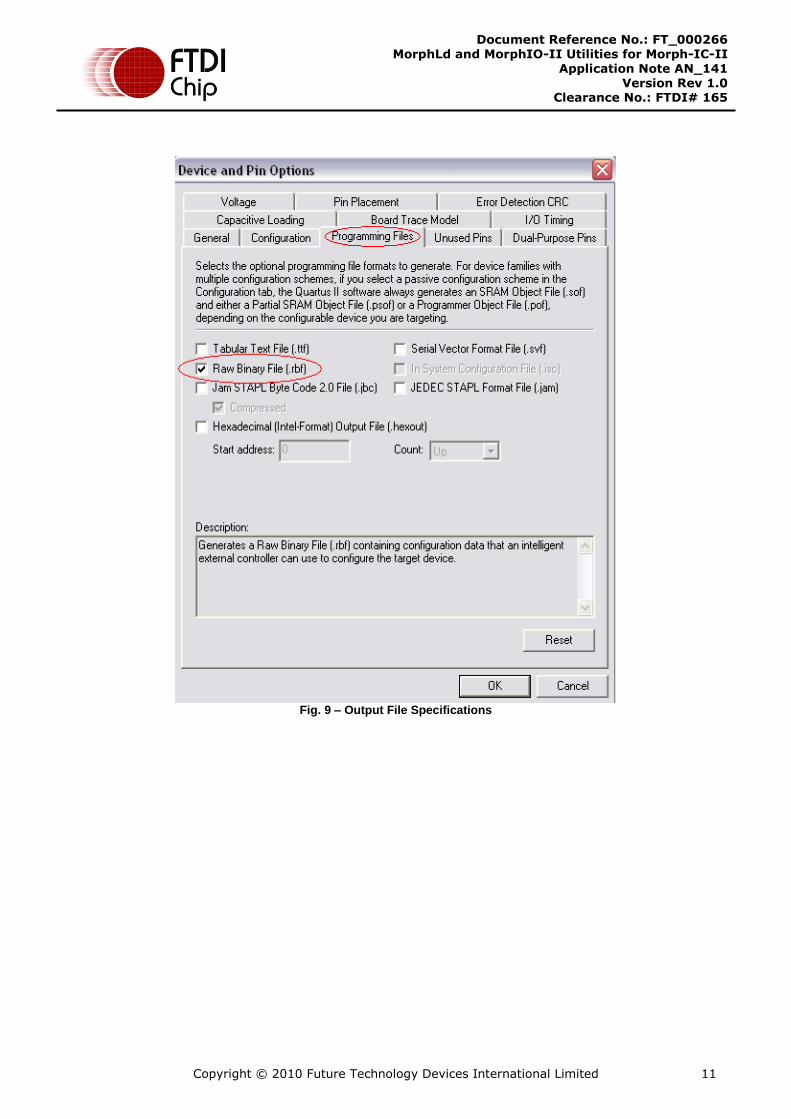
Select the *.RBF format for the programming file (see Fig. 9) – as required by MorphIO-II
Configure all Dual-Purpose pins to be general I/Os (see Fig. 10).
Fig. 7 – Device and Pin Options

Copyright © 2010 Future Technology Devices International Limited 10
Document Reference No.: FT_000266 MorphLd and MorphIO-II Utilities for Morph-IC-II
Application Note AN_141 Version Rev 1.0
Clearance No.: FTDI# 165
Fig. 8 – FPGA Configuration
Copyright © 2010 Future Technology Devices International Limited 11
Document Reference No.: FT_000266 MorphLd and MorphIO-II Utilities for Morph-IC-II
Application Note AN_141 Version Rev 1.0
Clearance No.: FTDI# 165
Fig. 9 – Output File Specifications

Copyright © 2010 Future Technology Devices International Limited 12
Document Reference No.: FT_000266 MorphLd and MorphIO-II Utilities for Morph-IC-II
Application Note AN_141 Version Rev 1.0
Clearance No.: FTDI# 165
Fig. 10 – Dual-Purpose Pins

Copyright © 2010 Future Technology Devices International Limited 13
Document Reference No.: FT_000266 MorphLd and MorphIO-II Utilities for Morph-IC-II
Application Note AN_141 Version Rev 1.0
Clearance No.: FTDI# 165
1.3 MorphLd - FPGA Loader
The Morph-IC-II package includes a utility called “MorphLd”.
MorphLd is a utility which is used to load *.RBF files to the Morph-IC-II module. These *.RBF files are generated when the Quartus-II compiles a HDL project.
The MorphLd is very simple to use. Files are loaded into the FPGA in four short steps. These steps are
shown in the screenshots illustrated in Fig 11.
First open the MorphLd.
Second select the *.RBF file to be loaded by clicking on “Browse” button and navigating to the *.RBF file generated by the Quatrus-II project application.
Third select the “Morph-IC-II B” device from „Device Names:‟ drop down list.
Finally click “Program” button to program the FPGA.
Fig. 11 – Using the MorphLd

Copyright © 2010 Future Technology Devices International Limited 14
Document Reference No.: FT_000266 MorphLd and MorphIO-II Utilities for Morph-IC-II
Application Note AN_141 Version Rev 1.0
Clearance No.: FTDI# 165
The MorphIO-II utility has as an *.RBF file loader embedded in the application code, which will load the “Morphio50m_Mii.rbf” file from the same directory as the MorphIO-II executable. This *.RBF file will contain all the details extracted from the “Morphio50m_Mii” project, which contains all the unsupported sample (HDL) hardware of the MorphIO-II application (listed in Section 2.0).
Since *.RBF files can be loaded into the FPGA in such short time (less that 0.1s) an application using the Morph-IC-II can reload several different *.RBF files to provide a different configuration to the FPGA “on-
the-fly”.
The “MorphLd” utility has two source code versions: Delphi and VB.NET. Different versions of this utility are provided to allow the source code to be used, or even modified, with applications written in different languages.
Another similar *.RBF loader is also included with the Morph-IC-II package. This utility is constructed from a number of LabVIEW programs.
An example of a hardcoded *.RBF loader with no interfacing is included in the Morph-IC-II package. This source code can be edited to suit applications that need an *.RBF files loaded using an interface based on
the C++ language.

Copyright © 2010 Future Technology Devices International Limited 15
Document Reference No.: FT_000266 MorphLd and MorphIO-II Utilities for Morph-IC-II
Application Note AN_141 Version Rev 1.0
Clearance No.: FTDI# 165
1.4 The MorphIO-II
1.4.1 Features
MorphIO-II is a utility for Morph-IC-II. It uses a GUI to set the logic levels and direction of the 80 I/Os of the Morph-IC-II module (see Fig. 12). This utility can also apply a clock signal, between 12.3 KHz and 50
MHz, to ten dedicated I/O pins. A feature for saving and loading configuration of the I/Os is also included in MorphIO-II. Additional control buttons are present in the GUI to set all the I/Os to the same status: All High, All Low, All In or All Out. The I/Os which are connected to I/O Bank4 are highlighted because these I/Os can be set to logic voltage levels between 1.8V and 3.3V, all other I/O pins are 3.3V only.
Fig. 12 – MorphIO-II GUI

Copyright © 2010 Future Technology Devices International Limited 16
Document Reference No.: FT_000266 MorphLd and MorphIO-II Utilities for Morph-IC-II
Application Note AN_141 Version Rev 1.0
Clearance No.: FTDI# 165
1.4.2 MorphIO-II User Guide
When the MorphIO-II program is executed, the screen shown in Fig. 13 is displayed.
Fig. 13 – Initial MorphIO-II Screenshot
In this GUI (Fig. 13) select a “Morph-IC-II device channel B” from the combo box under "Morphic Prog Device". Pressing "Start" will load the morphio50m_Mii.rbf file into the FPGA on the Morph-IC-II module. The resultant screenshot is illustrated in Fig. 14

Copyright © 2010 Future Technology Devices International Limited 17
Document Reference No.: FT_000266 MorphLd and MorphIO-II Utilities for Morph-IC-II
Application Note AN_141 Version Rev 1.0
Clearance No.: FTDI# 165
Fig. 14 –Morph-IC-II After Programming With morphio50m_Mii.rbf
The MorphIO-II GUI has a series of buttons and indicators used to specify and display the logic state or direction of an I/O. An example of these controls and direction indicators is shown in Fig. 15.

Copyright © 2010 Future Technology Devices International Limited 18
Document Reference No.: FT_000266 MorphLd and MorphIO-II Utilities for Morph-IC-II
Application Note AN_141 Version Rev 1.0
Clearance No.: FTDI# 165
Fig. 15 shows J1-15 and J1-19 set as outputs and all the other I/Os displayed are set as inputs. This observation is based on the black dots under the I/O column. If an I/O is an output, the black dot is checked in the button on the right beneath the “O”. If the I/O is an input the black dot is checked in the button on the left beneath the “I” Fig. 15 also illustrates there is a similar control interface for setting the logic levels of the outputs.
If the button located in the column beneath the “L” is checked then the signal is set to a logic low. Similarly if a button beneath the “H” is checked then the signal is set high.
Fig. 15 also shows that there are logic level indicators associated with the logic level buttons. These indicators display the logic state read from the I/Os of each pin on the Morph-IC-II module. If logic high is read the indicator in the “H” column will be red, if a logic low is read the indicator in the “L” column will be green.
Fig. 15 – Controlling the I/Os
Control for J1-13, shown in Fig. 15, also has an additional button shown to the left hand side of J1-13. This button can be used to select whether or not a clock signal is applied to this pin.
This clock button is available on other nine pins and they all have a similar function: enabling or disabling clock signals.
The frequency of these clock signals can be determined by clicking on the “Setup” button, selecting the “Clocks”, then selecting the pin number that the clock signal is being applied to and finally selecting the
required frequency from the list of available frequencies.
Referring back to Fig. 14, this also shows that there are 4 buttons (under the label ALL), each with a different letter: “L”, “H”, “I” and “O”.
The “L” button will set all I/Os as outputs and set them to logic low.
The “H” button will set all I/Os as outputs and set them to logic high.
The “I” button will set all I/Os as inputs.
The “O” button will set all I/Os as outputs.

Copyright © 2010 Future Technology Devices International Limited 19
Document Reference No.: FT_000266 MorphLd and MorphIO-II Utilities for Morph-IC-II
Application Note AN_141 Version Rev 1.0
Clearance No.: FTDI# 165
1.5 Reconfiguring the Logic Voltage Levels of Morph-IC-II
Morph-IC-II has a feature of being able to process signals of different logic voltage levels on the I/Os. To change the logic voltage levels two tasks needs to be completed.
The first task is to configure the application HDL to specify the I/O Standard used for each pin, this is carried out using the pin editor of Quartus-II.
The second task is to set the voltage levels supplied to the all I/O Banks within the Morph-IC-II module; this voltage should be within a 5% tolerance of the logic voltage levels of the I/O Standards of these I/O Banks.
The following steps illustrate this procedure.
Step 1: Open the pin-map editor of Quartus-II in the “morphio50m_Mii” project included in the source code directory provided in the Morph-IC-II download
Step 2: Set all the I/O Standards of Bank4 to the required level. An example of this is shown in Fig. 16
which sets the I/O Standard for I/O Bank 4 to 1.8V.
Fig. 16 – Configuring the I/O standard
Step 3: Close the pin editor and click run on the Quartus toolbar.
Step 4: Allow the compiler to run. Any errors introduced from the changes of the IO Standards causes a fail in the Quartus-II compiler to occur. The compiler will alert and point to the source of error. Once all errors have been corrected, Quartus-II will compile the application HDL to produce an output file. The format of this file is *.RBF.
Step 5: Copy and paste the generated *.RBF file to the same directory as the MorphIO-II application,
replacing the „morphio50m_Mii.rbf‟ located in the same directory as the MorphIO-II with the new file (and rename it „morphio50m_Mii.rbf).
With the modified .rbf file, the software can configure the Morph-IC-II module to accept signals of the newly specified IO voltage levels.
The next requirement is to remove the jumper “V_Bank4” (since the default onboard power supply is fixed to 3.3V) and apply an external voltage to the power supply of IO Bank 4 This externally applied voltage must match the logic voltage levels of I/O Bank 4 set in the previous step. When this jumper is
removed an external voltage supply must be applied to V_Bank4 nodes of the header “J2”.

Copyright © 2010 Future Technology Devices International Limited 20
Document Reference No.: FT_000266 MorphLd and MorphIO-II Utilities for Morph-IC-II
Application Note AN_141 Version Rev 1.0
Clearance No.: FTDI# 165
2 Utilities Source Code
The source code required to run the MorphIO-II utility are as follows:
Quartus-II compiler output Files
Morphio50m_Mii – Top level entity
Mcontrol_mII – Controls FIFO communications
Mwrap_mII – Wrapper for all sub-blocks of I/O control
Upcnt12l_mII – 12 bit up counter
Delphi Files – (Pascal source code used to run the Morph-IC-II GUI)
D2XXUnit – D2XX DLL unit.
DSjtag – Contains functions to program the FPGA and setup serial bit stream.
morphio – Contains the functions which interface to the GUI.
The source code required to run the MorphLd is also included in the Morph-IC-II package. The MorphLd is available for the following IDE design formats: Delphi, C++Builder, LabVIEW, Visual-Basic 6 and Visual-Basic.Net.

Copyright © 2010 Future Technology Devices International Limited 21
Document Reference No.: FT_000266 MorphLd and MorphIO-II Utilities for Morph-IC-II
Application Note AN_141 Version Rev 1.0
Clearance No.: FTDI# 165
3 Acronyms and Abbreviations
Terms Description
RBF Raw Binary File
GUI Graphical User Interface
JTAG Joint Test Action Group
HDL Hardware Description Language
Table 3.1 Acronyms and Abbreviations

Copyright © 2010 Future Technology Devices International Limited 22
Document Reference No.: FT_000266 MorphLd and MorphIO-II Utilities for Morph-IC-II
Application Note AN_141 Version Rev 1.0
Clearance No.: FTDI# 165
4 Contact Information
Head Office – Glasgow, UK
Future Technology Devices International Limited Unit 1, 2 Seaward Place, Centurion Business Park Glasgow G41 1HH United Kingdom Tel: +44 (0) 141 429 2777 Fax: +44 (0) 141 429 2758
E-mail (Sales) [email protected] E-mail (Support) [email protected] E-mail (General Enquiries) [email protected] Web Site URL http://www.ftdichip.com Web Shop URL http://www.ftdichip.com
Branch Office – Taipei, Taiwan Future Technology Devices International Limited (Taiwan) 2F, No. 516, Sec. 1, NeiHu Road Taipei 114 Taiwan , R.O.C. Tel: +886 (0) 2 8791 3570
Fax: +886 (0) 2 8791 3576 E-mail (Sales) [email protected] E-mail (Support) [email protected] E-mail (General Enquiries) [email protected] Web Site URL http://www.ftdichip.com
Branch Office – Hillsboro, Oregon, USA Future Technology Devices International Limited (USA) 7235 NW Evergreen Parkway, Suite 600 Hillsboro, OR 97123-5803 USA
Tel: +1 (503) 547 0988 Fax: +1 (503) 547 0987 E-Mail (Sales) [email protected] E-Mail (Support) [email protected] E-Mail (General Enquiries) [email protected] Web Site URL http://www.ftdichip.com
Branch Office – Shanghai, China Future Technology Devices International Limited (China)
Room 408, 317 Xianxia Road, Shanghai, 200051
China Tel: +86 21 62351596 Fax: +86 21 62351595 E-mail (Sales) [email protected] E-mail (Support) [email protected] E-mail (General Enquiries) [email protected]
Web Site URL http://www.ftdichip.com

Copyright © 2010 Future Technology Devices International Limited 23
Document Reference No.: FT_000266 MorphLd and MorphIO-II Utilities for Morph-IC-II
Application Note AN_141 Version Rev 1.0
Clearance No.: FTDI# 165
Distributor and Sales Representatives
Please visit the Sales Network page of the FTDI Web site for the contact details of our distributor(s) and sales representative(s) in your country.
Vinculum is part of Future Technology Devices International Ltd. Neither the whole nor any part of the information contained in, or the
product described in this manual, may be adapted or reproduced in any material or electronic form without the prior written consent of
the copyright holder. This product and its documentation are supplied on an as-is basis and no warranty as to their suitability for any
particular purpose is either made or implied. Future Technology Devices International Ltd will not accept any claim for damages
howsoever arising as a result of use or failure of this product. Your statutory rights are not affected. This product or any variant of it is
not intended for use in any medical appliance, device or system in which the failure of the product might reasonably be expected to
result in personal injury. This document provides preliminary information that may be subject to change without notice. No freedom to
use patents or other intellectual property rights is implied by the publication of this document. Future Technology Devices International
Ltd, Unit 1, 2 Seaward Place, Centurion Business Park, Glasgow G41 1HH United Kingdom. Scotland Registered Number: SC136640

Copyright © 2010 Future Technology Devices International Limited 24
Document Reference No.: FT_000266 MorphLd and MorphIO-II Utilities for Morph-IC-II
Application Note AN_141 Version Rev 1.0
Clearance No.: FTDI# 165
Appendix A - References
FTDI:
Morph-IC-II DATASHEET
FT2232H Hi-Speed Dual USB UART/FIFO IC Data Sheet
(http://www.ftdichip.com/Documents/DataSheets/DS_FT2232H.pdf)
D2XX Programmer's Guide
(http://www.ftdichip.com/Documents/ProgramGuides/D2XX_Programmer%27s_Guide%28FT_000071%29.pdf)
FTCJTAG Programmer's Guide
http://www.ftdichip.com/Documents/ProgramGuides/AN_110_Programmers_Guide_for_High_Speed_FTCJTAG_DLL.pdf
Command Processor For MPSSE and MCU Host Bus Emulation Modes
(http://www.ftdichip.com/Documents/AppNotes/AN_108_Command_Processor_for_MPSSE_and_MCU_Host_Bus_Emulation_Modes.pdf)
MPSSE Basics
http://www.ftdichip.com/Documents/AppNotes/AN_135_MPSSE_Basics.pdf
Altera Cyclone II:
Get Literature
http://www.altera.com/literature/lit-cyc2.jsp
Get Handbook (PDF)
http://www.altera.com/literature/hb/cyc2/cyc2_cii5v1.pdf
Get Data Sheet (PDF)
http://www.altera.com/literature/hb/cyc2/cyc2_cii5v1_01.pdf

Copyright © 2010 Future Technology Devices International Limited 25
Document Reference No.: FT_000266 MorphLd and MorphIO-II Utilities for Morph-IC-II
Application Note AN_141 Version Rev 1.0
Clearance No.: FTDI# 165
Appendix B - Revision History
Revision History
Version 1.00 Initial Release 13th August 2010