FUSION/HIGH-TEMPERATURE ELECTROLYSIS v i e • -.^ , '-it ...
141
BNL-33701 ^INFORMAL REPORT BNL—337 01 DE84 001475 HYFIRE II FUSION/HIGH-TEMPERATURE ELECTROLYSIS CONCEPTUAL-DESIGN STUDY r - ! vc To 0 " r -"'."-' -*5-ff?^ aaHH -* - H o .-"-3 '^w^^H i e • -."^ — _ jj. ^^ 0' •^Krfi -""*?%£ , '-"it, -3r „-. "^ ~* « %', -• " ~~Z ~ ^ &P •' - w . ''JftS. —•' * -~ ^ * r —t ~ *~ - * ' ANNUAL REPORT J.A. FILLO, EDITOR DEPARTMENT OF NUCLEAR ENERGY /' BROOKHAVEN NATIONAL LABORATORY UPTON, LONG ISLAND, NEW YORK 11973
Transcript of FUSION/HIGH-TEMPERATURE ELECTROLYSIS v i e • -.^ , '-it ...

BNL-33701INFORMAL REPORT
BNL—337 01
DE84 001475
HYFIRE IIFUSION/HIGH-TEMPERATURE ELECTROLYSIS
CONCEPTUAL-DESIGN STUDY
r -
!
vcTo
0
" r -"'."-' -*5-ff?^
aaHH
-* - H o .-"-3 ' ^ w ^ ^ H
i e • -."— _ j j . ^ ^
0' •^Krfi
- " " * ? % £
, '-"it, -3r„-. "^ ~*
« %', -• " ~~Z~ ^ &P•' -w . ''JftS.
—•' * -~ ^ * r
—t ~ *~ - * '
ANNUAL REPORT
J.A. FILLO, EDITOR
DEPARTMENT OF NUCLEAR ENERGY
/'
BROOKHAVEN NATIONAL LABORATORYUPTON, LONG ISLAND, NEW YORK 11973

BNL-33701INFORMAL REPORT
HYFIRE II: FUSION/HIGH-TEMPERATURE ELECTROLYSISCONCEPTUAL-DESIGN STUDY
ANNUAL REPORT
J.A. Fillo, Editor
Department of Nuclear EnergyBrookhaven National Laboratory
Upton, New York 11973
AUGUST 1983
NOTICEPORTmNS^rrHisjiEPoaT^^It has been reproduced from the bestavailable copy to permit the broadestpossible availability.
DISTRIBUTION OF THIS OOCUMENT IS UNLIMITED
H
DISCLAIMER
This Report was prepared as an account of work sponsored by an agency of theUnited States Government. Neither the United States Government nor anyagency thereof, nor any of their employees, makes any warranty, express orimplied, or assumes any legal liability or responsibility for the accuracy,completeness, or usefulness of any information, apparatus, product, orprocess disclosed, or represents that its use would not infringe privatelyowned rights. Reference herein to any specific commercial product, process,or service by trade name, trademark, manufacturer, or otherwise, does notnecessarily constitute or imply its endorsement, recommendation, or favoringby the United States Government or any agency thereof. The view and opinionsof authors expressed herein do not necessarily state or reflect those of theUnited States Government or any agency thereof.
-ii-

LIST OF CONTRIBUTORS
Brookhaven National Laboratory
R. BenenatiJ.A. Fillo
F. Horn0. Lazareth
J.R. Powell
Westinghouse
Principal Investigator Editor Project ManagerF.S. Malick M. Sniderman R.P. Rose
Contributors :
J.W.H. Chi R.E. Grimble M. SnidermanK.J. Garber D.Q. Hoover E.V. SommersG. Gibson F.S. Malick J.S. Karbowski

TABLE OF CONTENTS
Page
EXECUTIVE SUMMARY .i
1.0 Introduction 1
2.0 High-Temperature Electrolyzer Design 22.1 Elecrolyzer Design Fundamentals 22.2 Electrolyzer Tube and Vessel Designs .5
3 .0 Process /Power Cycle 153.1 Reference Power Cycle Design 15
4.0 Fusion/HTE Plant Integration 244.1 Introduction 244.2 HYFIRE Tokamak Site Plan 274.3 HYFi::.-: Tokamak Reactor Building 294.4 HYFIRE Tokamak Process Module Room of the Reactor Building 334.5 HYFIRE Tokamak Electrolyzer Building 344.6 HYFIRE Tokamak Turbine Building 374.7 HYFIRE Tokamak Hot Cell 424.8 Hydrogen and Water Separation Building 434.9 HYFIRE Tokamak Tritium Reprocessing and Cryogenic Building 454.10 Electrical and rf Power Supply Building 494.11 Heat Rejection System 51
5.0 Costing Analysis 535.1 General , 535.2 Hydrogen Producing Components for HYFIRE 555.3 Capital Cost Account 57
ACKNOWLEDGEMENTS 90
REFERENCES 90
APPENDIX A , A-l
APPENDIX B B-l
APPENDIX C C-l

EXECUTIVE SUMMARY
As in the prev ious HYFIRE des ign s tudy , the c u r r e n t study focuses on cou-
p l i n g a Tokamak fusion r e a c t o r wi th a h i g h - t e m p e r a t u r e b lanket to a High-
Temperature E l e c t r o l y z e r (HTE) process to produce hydrogen and oxygen. Sca l ing
of the STARFIRE r e a c t o r to a l low a blanket power to 6000 MH(th) i s a l so a s -
sumed. The pr imary d i f f e r ence between the two s t u d i e s i s the maximum i n l e t
steam temperature to the electrolyzer. This temperature is decreased from
"1300° to ~1150°C, which is closer to the maximum projected temperature of
the Westinghouse fuel cell design. The process flow conditions change but the
basic design philosophy and approaches to process design remain the same as be-
fore. Westinghouse assisted in the s*"udy in the areas of systems design inte-
gration, plasma engineering, balance-of-plant design, and electrolyzer
technology.
The guidelines for this study were essentially similar to those used in the
development of the STARFIRE reference Tokamak reactor design. The final HYFIRE
plant embodiment was to represent the tenth-of-a-kind first generation plant.
STARFIRE technology assumptions and design features were to be used to the ex-
tent possible to permit concentration on high-temperature blanket and balance-
of-plant design issues.
In addition to the requirement for tritium self-sufficiency, an important
ground rule for this ini t ial series of studies was that hydrogen would be the
only product produced for sale. Thus, the electrical generation equipment and
the overall power conversion process would be sized to exactly provide the elec-
trical energy required to operate the Tokamak, electrolysis plant, and balance-
of-plant systems.

-ii-
A complete process flow sheet has been developed for the system coupling
the high-temperature blanket to the high-temperature electrolysis and electrical
power generation subsystems, and material flow and energy balances accomplished
through the development of a digital computer code to represent the overall
cycle.
The overall plant can be thought of as having four principle process
circuits:
1. the low-temperature water loop which extracts heat from the front wall
of the blanket elements;
2. the helium loop;
3. the steam-hydrogen loop which provides the dual function of electrici-
ty generation and hydrogen production; and
4. the waste oxygen circuit.
The steam-hydrogen loop is by far the most involved.
Low-temperature water which extracts heat from the first wall and high-
temperature helium are used to raise steam for the high-pressure turbine which
is then used to make electricity to operate the electrolyzers, fusion reactor,
and balance-of-plant.
Since only about 10% of the steam is converted to hydrogen per pass, some
effort is required to separate and recycle the steam so that product hydrogen
can meet purity specifications. The steam is condensible at normal ambient con-
ditions and the hydrogen is not. Thus, the recovery scheme involves cooling the
mixture followed by condensation of the steam and subsequent phase separation.
To achieve a product hydrogen steam in excess of 99% purity, an eight-stage
condenser/compressor string is used.

-in-
Table I summarizes key cycle parameters associated with the high-
temperature design point. The thermal power to the electrolyzers is ~30% of
the total power required to operate the electrolyzers for electrolysis of
steam. The overall efficiency to produce hydrogen from fusion energy is 50%.
In summary, the HYFIRE studies to date have investigated a number of tech-
nical approaches for using the thermal energy produced in a high-temperature
Tokamak blanket to provide the electrical and thermal energy required to drive a
high-temperature water electrolysis process. Current emphasis has been on two
design points, one consistent with electrolyzer peak inlet temperatures, of
~1300°C, which is an extrapolation of present experience, and one consistent
with a peak electrolyzer temperature of 1100°C. This latter condition is based
on current laboratory experience with high-temperature solid electrolyte fuel
cells.
The Tokamak driver for HYFIRE is based on the STARFIRE reference commercial
fusion power plant design. A reference blanket design has been selected, incor-
porating modules designed to produce high-temperature steam and modules designed
to breed tritium and provide process heat. Process design and plant layout has
been completed; component cost and plant economics studies show hydrogen produc-
tion costs to be $7.14/MBtu. This cost compares competitively with the price of
hydrogen generated from natural gas and coal which ranges from $4.00 to $7.00.
In addition, the technical integration of fusion and high-temperature electroly-
sis appears to be feasible and that overall hydrogen production efficiencies of
50 to 55% seem possible.

-iv-
TABLE I
SUMMARY OF HYFIRE PLANT PARAMETERS
Gross Blanket Thermal Power, MW(th)
Steam Exit Temperature, °C
Helium Exit Temperature, °C
Pressure Turbine Inlet Pressure, °C
Pressure Turbine Inlet Pressure, MPa
Pressure Turbine Inlet Temperature, °C
Pressure Turbine Inlet Temperature, MPa
Electrical Power to Electrolyzers, MW(e)
Thermal Power to Electrolyzers, MW(th)
Production: Metric Ton/Day
kg/hr
Fusion Power to Hydrogen Conversion Efficiency, %
6000 Blanket
1142 Blanket
732
538 High
8.50 High
474 Low
3.38 Low
1620
650
1580
65830
50

-1-
1.0 INTRODUCTION
As in the previous'-' HY.FIRE design study, the current study focuses on
coupling a Tokamak fusion reactor with a high-temperature blanket to a High-
Temperature Electrolyzer (HTE) process to produce hydrogen and oxygen. Scaling
of the STABFIRE reactor to allow a blanket power to 6000 MW(th) is also as-
sumed. The primary difference between the two studies is the maximum inlet
steam temperature to the electrolyzer. This temperature is decreased from
"1300° to ~1150°C, which is closer to the maximum projected temperature of
the Westinghouse fuel cell design. The process flow conditions change but the
basic design philosophy and approaches to process design remain the same as
before.
The current report does not go into as much detail as Ref. (1). For exam-
ple, since the blanket design does not change except for the thermal hydraulics
(and thermo-mechanical aspects of the design) because of the lower steam temper-
atures, a section on blanket design does not appear. In some cases, where in-
formation has been updated or new work has been carried out, flections have been
repeated and expanded. As previously, Westinghouse assisted in the study in the
areas of systems design integration, balance-of-plant design, electrolyzer tech-
nology, and systems costing.
Coverage of the basic contents of the report are identified in the follow-
ing sections. Section 2 covers the HTE modeling and reference design. Section
3 discusses tha plant process and powt- conversion design. Section 4 covers
plant integration, and Section 5 is a detailed accounting of plant economics.
-2-
2.0 HIGH-TEMPERATURE ELECTROLYZER DESIGN
This Section provides a summary of the principles of high-temperature elec-
trolysis and descriptions of the designs of the high-temperature electrolier
(HTE) and the associated synfuel plant.
2.1 Slectrolyzer Design Fundamentals
In a previous repotw^) the fundamentals of high-temperature electrolysis
were discussed. Some of this information has been updated.
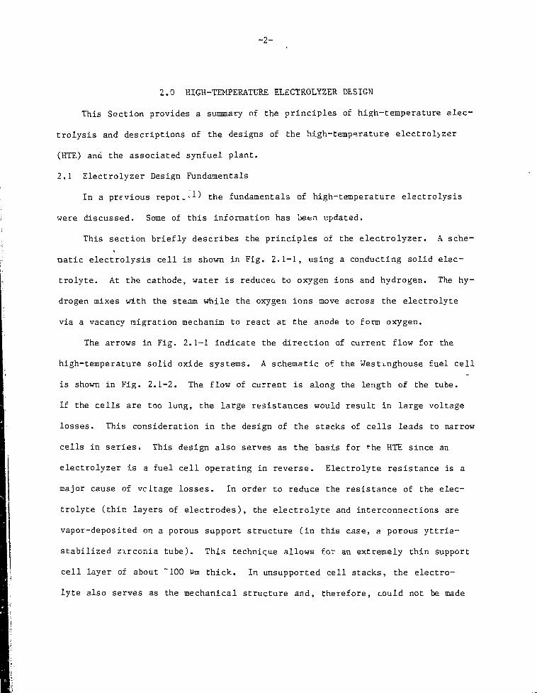
This section briefly describes the principles of the electrolyzer. A sche-
matic electrolysis cell is shown in Fig. 2.1-1, using a conducting solid elec-
trolyte. At the cathode, water is reducea to oxygen ions and hydrogen. The hy-
drogen mixes with the steam while the oxygen ions move across the electrolyte
via a vacancy migration mechanim to react at the anode to form oxygen.
The arrows in Fig. 2.1-1 indicate the direction of current flow for the
high-temperature solid oxide systems. A schematic of the Westinghouse fuel cell
is shown in Fig. 2.1-2. The flow of current is along the length of the tube.
If the cells are too long, the large resistances would result in large voltage
losses. This consideration in the design of the stacks of cells leads to narrow
cells in series. This design also serves as the basis for *"he HTE since an
electrolyzer is a fuel cell operating in reverse. Electrolyte resistance is a
major cause of vcltage losses. In order to reduce the resistance of the elec-
trolyte (thin layers of electrodes), the electrolyte and interconnections are
vapor-deposited on a porous support structure (in this case, a porous yttria-
stabilized zirconia tube). This technique allows for an extremely thin support
cell layer of about ~100 Vm thick. In unsupported cell stacks, the electro-
lyte also serves as the mechanical structure and, therefore, could not be made

H2°GAS
OXYGEN ELECTRODE
ELECTROLYTE
HYDROGENELECTRODE
2 GAS
FIGURE 2.1-1
SCHEMATIC OF HIGH TKMl'ERATURE ELECTROLYSIS

ELECTROLYTE
IN
2 ELECTRODE
\ I 1 t
POROUS SUPPORT STRUCTURE
INTERCONNECTION OXIDE
OUT
H2 + H20
OUT
FIGURE 2 . 1 - 2
hTE CELL DESIGN(WESTIUGHOUSE FUEL CELL)

too thin because of strength limitations, but this is not the case in the cur-
rent design.
The efficiency of the electrolyzer is a function of the voltage losses
which increase the operating potential of the cells to values greater than that
given by the Nernst Equation. The additional voltage required or overpotential
arises from the resistances of all the components: the anode, cathode, electro-
lyte and interconnections between cells in the stack, and the kinetic limita-
tions of the electrode reactions at the anode. These limitations depend on the
diffusion of th*- water, hydrogen, or oxygen in the pores of the electrode struc-
ture, hence they depend on the electrode morphologies and materials. The resis-
tances are established by physical properties, material resistivities, and
thicknesses o? the electrode, electrolyte, and interconnections.
The voltage losses increase the electrical energy required for electrolysis
and as this energy is lost in the form of heat, less direct sensible heat must
be supplied to the electrolyzer. The overall net result is an increased con-
sumption of exectrical energy and a reduction in plant efficiency. The electri-
cal losses also increase with increasing cell current density, but increasing
current density reduces the size of the plant and its capital costs for a parti-
cular hydrogen production rate. Therefor"-., a compromise must be struck.
2.2 Electrolyzer Tube snd Vessel Designs
The design of an HTE occurs in two steps. The first defines the electro-
lyzer tube geometry and materials and establishes the performance characteris-
tics of the elcctrolyzer tube; the second consists in design of the repetitive
arrangement and assembly of thousands of the tubes within the HTE containment
vessel. The definition of the electrolyzer tube materials and geometry follows
-6-
the development work being conducted by Westinghouse on its high temperature
solid oxide fuel cell that can reach hot spot temperatures of 1100°C. The elec-
trolyzer tube geometry has two design options: One, construction of an electro—
lyzer tube as a single ele trolyzer cell or as a multicell tube with the cells
connected electrically in series along the length of the tube; and two, con-
struction of the electrolyzer tube either to handle the steam-hydrogen flow on
the inside of the tube (and the oxygen flow on the outside of the tube) or to
handle the steam-hydrogen flow on the outside of the tube (and the oxygen flow
on the inside of the tube). The construction of a series-connected multicell
with the steam-hydrogen flow confined to the inside of the tube has been select-
ed by Brookhaven National Laboratory (BNL) for the HTE design.
Three operating conditions must be defined for the electrolyzer: 1) the
inlet steam temperature and with it the electrolyzer tube temperature profile;
2) the current density within the cells of the series-connected multicell tube;
and 3) either the steam flow rate, which along with the above two conditions,
determines the steam-to-hydrogen molal ratio or the molal ratio, which deter-
mines the steam flow rate.
A simple design procedure has been developed to predict the performance of
a series-connected multicell tube that can reasonably be assumed to be isother-
mal at the mean temperature of the inlet and outlet streams. This design pro-
cedure is described in Appendix A. With the tube geometry, tube materials, tube
temperature, and inlet steam-to-hydrogen molal ratio identified, the first step
of I he design establishes the variation of the R-factor (defined as the ratio (if
the electric energy added to the tube to the thermal energy added from the steam
to the tube), and the variation of the tube voltage with parametric variation of

-7-
the current density in the electrolysis cells. Such a parametric variation,
shown in Fig. 2.2-1, is calculated for a typical tube geometry and with typical
tube materials, as described in Appendix A.
Although Appendix A deals with the design option of oxygen inside the tube,
the results can be applied with little error to the inverted tube geometry with
the oxygen on the outside as used in the plant reference design. The electro-
lyte dimension used in the plant design i-'• the same as that described in Appen-
dix A. The important dimensions related to the plant tube geometry are the
following:
Support Tube, i.d. 1.19D cm
Support Tube, o.d. 1.390 cm
Electrode, o.d.: 1.A10 cm
Electrolyte, o.d. 1.418 cm
0x>gen Electrode, o.d. 1.558 cm
Length 156 cm
The second step of the design of the HTE consis's of selecting a current
density and with it the number of electrolyzer tubes needed to electrolyze the
preselected design production rate of hydrogen.
A computer program (Appendix B) was developed to calculate the HTE tube
performance with temperature varying along the length of the tube such that i t
follows the temperature profile of the steam-hydrogen stream. In addition, dif-
fusion polarization values are included to describe more accurately the electro-
lyzer tube performance. The code assumes a series-connected multicell structure
with the oxygen inside the tube.
In the HYFIRE Tokamak plant, there are twenty-eight electrolyzers, i . e . ,
one electrolyzer for each blanket sector. This simplifies the headering system

- 8 -
1.0
11% STEAM CONVERSION. 1100°C
UJCD
VOLTAGE
aIXuj
0.9
0.8
3.0
0.0 0.1 0.2 0.3
(a/cm2) CURRENT DENSITY
2.00.4 C.5
FIGURE 2 . 2 - 1
R-Factor for Tube and Average Cell Voltage vs. Cell Current Density

- 9 -
and reduces the cost by providing common components. The electrolyzcr assembly
consists of tube sheets inserted in a cooled steel pressure vessel, internally
insulated, which operates at ~30 .~'_:a. Steam is fed to the electrolyzer where
water is reduced to hydrogen on one side of the electrolyte and oxygen is l iber-
ated on the other. Since only ~10% of the steam input is converted to hydro-
gen in a single pass, the steam exiting the electrolyzer vessel iz a mixture of
steam and hydrogen. At a later stage in the process, the steam is condensed to
water, leaving behind hydrogen at virtually 100% purity. This is discussed in
detail in Section 3.
The plant electrolyzer tubes are constructed as shown by the schematic in
2
Fig. 2.2-2. A current density of 0.5 A/cm in the electrolyte was used and it
was assumed that 0.80 of the tube length was effective electrolyte. The thick-
ness of the oxygen electrode was taken as 0.05 cm so that the diameter of the
electrolyte is the tube o.d. minus 0.10 cm. The tubes are closed at one end and
each end has a conduction oxide layer. At the closed end, the conducting sur-
face oxide is in electrical contact with an oxide cap which passes through the
insulation. The end of the cap is at a temperature where metal i n be used in
the oxidizing atmosphere. The metal continues the electrical path to a conduct-
ing plate at each end of the vessel. The plate, in turn, is connected to an in-
sulated terminal through the pressure vessel. The open end of the electrolyte
support tube with its conducting oxide is sealed into the tube sheet section
with a conducting seal. The seal, in turn, makes contact with a conducting
seal. The seal makes contact with a conducting oxide lacing the tube sheet
sections which are also sealed together with a conducting ceramic seal.
As Fig. 2.2-2 indicates, the steam entering the HTE is distributed from the
central plenum through feed tubes. The feed tubes can be joined to tubes that

^CONDUCTINGOXIDE
COPPERBUS BAR
TUBESUPPORT
H2O IN
TUBESUPPORT
ANDINSULATION
oi
OUT
FIGURE 2 . 2 - 2
DETAILED CROSS-SECTION OF HTE CELL

-11-
are sealed together. A feed tube has spacers to center it in theelectrolyte
tube and can support the outer tube at high temperatures if required. The feed
tubes are centered within the electrolyte support tube. It then passes between
the tube and feed tubes to the second plenum. During passage, the gas diffuses
across the porous support tube to the cathode where it is electrolyzed to hydro-
gen and cooled by the endothermic reaction.
The two tube sheets which hold the feed tubes are the electrolyte support
tubes, respectively. Both are constructed as interconnecting sections which are
sealed together with a ceramic braze. A schematic of the tube sheet section is
shown in Fig. 2.2-3, which consists of V-notched edges which fit into adjacent
sections. The shapes of the sections are designed to conform with the ceramic
insulation and support around the walls. A triangular tube spacing with a spac-
ing to tube o.d. ratio of 1.25 was assumed.
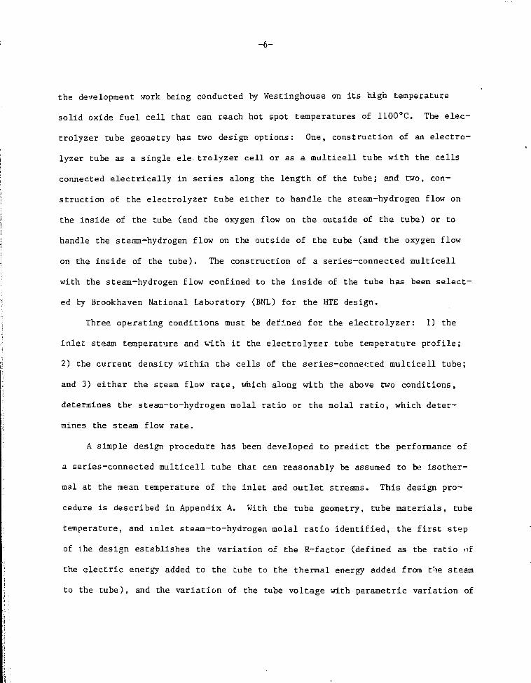
Figure 2.2-4 is a cross section through an electrolyzer showing how the
1.5-meter-long tubes are arranged inside the vessel. The total hydrogen produc-
tion of 1.45 x 10 lb/hr called for in the HYFIRE Tokamak process flow sheet
with the electrical to thermal ratio, R, equal to 2.5 is obtained with 375,000
tubes in each of twenty-eight electrolyzers operating at a current density of
0.30 A/cm . The spacer tubes with a triangular pitched array have a center-to-
center spacing of 1.73 cm which gives a clearance between tubes of .29 cm. A
2design with 0.50 A/cm will have 225,360 tubes spaced 2.4 cm center-to-center
but the electrolyzer will operate with R = 3.07 instead of 2.5 as called for in
the process flow sheet. The diameter of the vesstl is on the order of 6 m and
the height is 15.9 m. Each central plena receives the high—temperature steam
entering the HTE. Two adjacent plena collect the gas after electrolysis has

-12-
FIGURE 2.2-3
TUBE SHEET SECTION
-13-
ONE OF HUNDREDSOF ELECTROLYZERTUBES
15.90 m
OXYGEN PLENUMOUTSIDE OF TUBES
8.9 cmWALL TYP
STEAM+HYDROGEOUTLETS027 m DIA TYP
12.7 cmINSULATION TYP
O2 OUTLET0.20 m DIA
0.50 m
FIGURE 2.2-4
Cross-Section of pieotroly7.er

-14-
taken place in the tubes. These are next to the large plena in which the oxygen
is collected. The two end sections of the HTE unit are at low temperatures, and
house electrical connections at the end of the electrolyte tubes.
A major factor in the design of the electrolyzers is the minimization of
thermal stresses due to heating, cooling, and temperature cycling during opera-
tion. The outer cooled region of the containment vessel is held at virtually
constant temperature at all times and will not experience any significant prob-
lem. Iaternal components, on the other hand, will experience temperature
changes of over 1000°C and large dimensional changes when the HTE unit starts
up from or shuts down to room temperature. The tubes, for example, are designed
so that one end is fixed, with the other free to move to accommodate the dimen-
sional changes.

-15-
3.0 PROCESS/POWER CYCLE
3.1 Reference Power Cycle Design
The high-temperature water electrolysis process in HYFIRE is intimately as-
sociated with the electrical power generation process. Both orocesses are shown
on a single flow sheet, Fio. 3.1-1. The same water which flows through the
power cycle flows through the electrolysis units. The design parameters have
been balanced out so that for the entire plant, the only products (excluding
fuel for the reactor) which cross plant boundaries are water and hydrogen.
A. Overall Energy Flow in HYFIRE
The HYFIRE process described in this report is capable of converting
the fusion energy into thermochemical energy of hydrogen. The overall energy
flow from the Tokamak blanket is shown in Fig. 3.1-2. The distribution of fu-
sion energy to high-temperature steam modules or to helium modules is arbitrary
and depends on the assumed coverage of the first wall by either type of module.
Within both the high-temperature steam modules and the helium modules, the dis-
tribution of fusion energy to the relatively low-temperature first wall coolant
or to the higher temperature regions depends on the reutronics of the module
composition. The combination of these two effects is shown in Fig. 3.1-2, i.e.,
39% of the total energy goes to the first wall and of the remainder, 44% goes to
helium and 17% goes to high-temperature steam. This results in a blanket cover-
age of 38% for steam modules and 62% for helium modules.
The helium and first wall coolant together raise 638°C, 83 atm super-
heated steam in the specially designed boiltr-superheater.
The intermediate pressure steam discharging from the HP turbine has
its energy content augmented by the fusion energy which is deposited in the
high-temperature region of the steam modules. Thus, a total of 11% of the

COMPRESSOR/INTERCOOLER SYSTEM
HYFIRF PROCESS FLOWSHEET
WATFRPUMP
©MAIN v ^CIRCULATOR FEED I
PRi'HEATER I
HYDROGENPRODUCT
I
MAKEUP" WATER
I-EEDPUMP
K1GUKE 3 . 1 - 1

- 1 7 -
FUSIONBLANKET6000 MW
WATER—2367 MW(TO I'OWER CYCLE)
STEAM—1017 MW (TO UTE)
HELIUM—2616 MW (TQ POWER CYCLE)
FIGURE 3.1-2 OVERALL ENERGY FLOW

-18-
fusion energy enters the high-temperature electrolysis cells where somewhat less
than 650 MW(th) of the energy content of the inlet stream is required for the
decomposition of 10% of the water into hydrogen and oxygen.
The effluent products of the HTE, namely, steam, hydrogen, and oxygen
pass on to the remainder of the power generating cycle. In a l l , some 37% of the
fusion energy is converted to electricity, the bulk of which is sent to the HTE
to satisfy their electrical energy need. An assumed 150 MW(e) is recycled to
the CTR for rf heating and the remainder of the electrical energy is required by
the several pumps, blowers, and compressors as shown on the flow sheet. The
electrical power to the primary helium circulator is high, having been calculat-
ed at 188 MW(e).
B. Point Design Process/Power Cycle Analysis
The overall process/power cycle flow sheet shown in Fig. 3.1-1 in-
volves the conversion of fusion energy (thermal) to gaseous hydrogen via water
electrolysis at the highest temperature possible consistent with the best tech-
nology and materials currently available. Since the plant is to generate its
own electricity to run the electrolyzers as well as to satisfy al l other elec-
trical requirements (but with no net electricity for export), there is a re-
quirement to provide steam generators, turbines, condensers, feed-water heaters,
etc. , th?t i s , the usual components of a steam-electric power plant. From the
point of view of the fusion reactor, there is the need to breed tritium which
imposes restrictions on materials of construction for the blanket components as
well as for process fluids, i . e . , coolant streams. We have elected to satisfy
these diverse requirements by designing the blanket with three distinctly
different heat generation zones, each with i ts own process fluid and each with
its own set of process parameters.

-19-
One zone which involves the first wall of all modules operates at the
relatively modest tempe. ature of 340°C (average) and is kept cool by this cir-
culation of pressurized water at 193 atm. The pressurized water coolant from
this zone is circulated through a steam generator in which 83 atm saturated
steam is generated on the secondary side.
Another zone, which lies behind the first wall of the power modules is
optimized for tritium breeding. This zone will operate at ~700°C and is cool-
ed by pressurized (30 atm) helium which exchanges heat wiuh a secondary helium
stream (at "70 atm) in small heat exchangers outboard of the blanket.
The third and final zone, which lies behind the first wall of the re-
maining steam-cooled blanket modules, is designed with the needs of the high-
temperature electrolyzers in mind. This zone will operate in excess of 1000°C
and serves to resuperheat relatively low pressure (30 atm) steam to ~1142°C
before it goes into the electrolyzers. All of the heat from this zone of the
blanket is used to provide the thermal energy required to dissociate water in
the electrolyzers.
The overall plant can be thought of as having four principle process
circuits:
1. the low-temperature water loop which extracts heat from the first
wall of the blanket elements;
2. the helium loop;
3. the steam-hydrogen loop which provides the dual function of
electricity generation and hydrogen production; and
4. the waste oxygen circuit.
The steam-hydrogen loop is ;<y far the most involved.

-20-
To simplify plumbing between4 the electrolyzers ard blanket, steam is
transported from the blanket to the electrolyzcrs in a single pass. The conver-
sion per pass through the entire cycle is approximately what was the conversion
per pass with multiple recycle through a single HTE in the earlier design con-
cept. The present design is somewhat less efficient but is probably somewhat
more realistic.
Make-up water is added to recycled water and together they enter a
train of feed-water preheaters for which suitable deionization facilities will
be required. This water is heated to 142°C, by extraction streams taken from
the various turbines, at which temperature it enters the boiler-superheater. In
the boiler-superheater, heat is supplied by the water coolant to the first wall
as well as by the hot helium. The relative duties provided by these two streams
as well as the temperature driving forces in the boiler-superheater have been
determined. The high-pressure superheater steam passes directly to the high-
pressure turbine where some 524 MW of electric power is produced. The discharge
sceam is reheated in a ceramic regenerator after which it flows to the high-
temperature steam modules in the blanket where it picks up about 1017 MW of
thermal energy. It leaves at 1142°C at which temperature it enters the HTE
units. The effluent from the HTE units pass through the ceramic regenerator and
flow onto the low pressure turbine.
From the point of view of the power cycle, the high-temperature elec-
•-Tolyzers and their associated equipment has merely served to supply reheat to
the steam leaving the high-pressure turbine. The total power output from the
low-pressure turbine is somewhat over three times the output of the high-
pressure turbine or about 1629 MW. The feed preheat: exchangers which take ex-
traction steam from the low-pressure turbine must be designed in such a way as

-21-
to permit recovery of the hydrogen contained in the extraction stream. Further-
more, they must be designed with careful attention to countercurrent flow, at
least so far as the hydrogen component is concerned, in order to reduce the
moisture content of the hydrogen to as low a level as is practical.
The flow sheet shown in Fig. 3.1-1 has the oxygen product from the
electrolyzers passing through the hot regenerator to the oxygen turbine and
finally to a fuel preheat exchanger. If this waste oxygen is passed through the
boiler-superheater instead of the hot regenerator, overall cycle efficiency in-
creases somewhat since i t results in a slightly recuced helium flow and a re-
duced amount of electricity consumed by the primary and secondary helium
blowers.
C. Process Flow Sheet Summary
The process flow sheet which is shown in Fig. 3.1-1 contains four
major process systems which are operating simultaneously in a highly coupled
mode, namely:
1. DT fusion reactor;
2. steam/electric power system;
3. high-temperature electrolysis of water; and
4. hydrogen drying.
The DT fusion reactor has three functionally different coolant streams
namely:
1. relatively cool water cooling the first wall of all modules;
2. hot helium cooling the interior of some modules; and
3. superheated steam cooling the interior of the remaining modules.
Streams 1 and 2 provide a thermal coupling to the steam electric power
cycle since they jointly provide the energy to raise the steam. Thus, Streams 1

-22-
and 2 serve to determine how much steam will circulate through the power tur-
bines and therefore have a direct influence on how much electrical power will be
produced. Stream 3 provides a thermal coupling to the electrolysis process
which is endothermic. Stream 3, therefore, has a direct influence on how much
hydrogen product is made.
The steam-electric power cycle generates the electricity required to
run all pumps, blowers, compressors, fusion reactor needs, and finally, the
electric power needs of the HTE. It is through these electrical requirements
(and the constraint that the overall process have a zero net electric genera-
tion) that this system is coupled to Systems 1, 3, and 4 above.
The hydrogen drying process consists of a series of compressors and
cooler-condensers each of which removes a small portion of the residual under-
composed steam, while rejecting heat only to the atmosphere, i.e., no refrigera-
tion is required. A total of eight stages of compression has been proposed with
the same pressure ratio in each storage. Since the first few stages have a much
larger flow than do the last few stagps, it may be that a more judicious distri-
bution of pressure ratio throughout the eight stages may result in an overall
reduction of electric power requirements. It is also possible that replacing
some of the initial compression stages with an absorption-desorption scheme for
removing the water, with the heat of desorption coming in part from the heat of
compression may also result in a significant reduction in electrical ene-gy re-
quirements. Table 3.1 is a summary of the HYFIRE plant parameters.

-23-
TABLE 3.1
SUMMARY OF HYFIRE PLANT PARAMETERS
Gross Blanket Thermal Power, MW(th)
Steam Exit Temperature, °C
Helium Exit Temperature, °C
Pressure Turbine Inlet Temperature, °C
Pressure Turbine Inlet Pressure, MPa
Pressure Turbine Inlet Temperature, °C
Pressure Turbine Inlet Pressure, MPa
Electrical Power to Electrolyzers, MW(e)
Thermal Power to Electrolyzers, MW(th)
Production: metric ton/day
kg/hr
Fusion Power to Hydrogen Conversion
Efficiency, %
6000
1142
732
538
8.50
474
3.38
1620
650
1580
65830
Blanket
Blanket
High
High
Low
Low
50

-24-
4.0 FUSION/HTE PLANT INTEGRATION
4.1 Introduction
The objective of the design of the plant facilities for the two HYFIRE de-
signs (Tokamak and Tandem Mirror) was to make them as similar to exisitng gener-
ic Tokamak and/or Mirror Fusion plants as feasible. Utilizing the study con-
straint, to the extent possible, that the HYFIRE reactor design was to be based
on the STARFIRE Tokamak Commercial Power Reactor (Ref. 1), the STARFIRE site
plant and building layouts, shown in Figs. 4.1-1 an- 4.1-2, were used as the
starting point for the HYFIRE Tokamak design. The general arrangement of the
building and component transport system used for remote assembly and disassembly
have been retained. The only changes that have been made for HYFIRE Tokamak
are those required for the production of the hydrogen synthetic fuel and oxygen,
and by the change in the thermal power level. The degree of detail shown in the
STARFIRE design could not be provided by the lower budget for the HYFIRE proj-
ect. The general description which follows will be for the HYFTRE Tokamak and
utilizes some of the information previously reported in Ref. 2 modified as nec-
essary to apply the latest design criteria.
The Fusion/HTE plant integration conceptual design has been carried out in
accordance with the process flow diagram and process flow conditions given in
Section 3, Process/Power Cycle. This Section of the report will discuss the
building's physical condition, sizes of some of the components, and special con-
siderations which influence the plant layout. This work was used to establish
building sizes and locations. The development of the costing information will
be covered in Section 5, Costing Analysis.
The site plan and the building locations are described. The basis for the
sizing of the components is then described on a building-by-building basis.

®
®
&
J
11 41 at
ttHW IWlLDI*
oumwuc amL i un v i a uimannw cmsDt i vaaia tut*amDua Bumoa w>
©®©©
©
MDUtam
tltlBUi VOtMl I'ma Ma UK
ontoxin i
MPKUI
nniarfULoactnanaattnucnuimj
I ICKIKI. ikUL
ftiiunuaumiia.
to
I
FIGURE 4.1-1 STARFIRE SITE PLAN

-26-
illliiiiiiiiililiiilliii©©©©0©©©©®@@@©(S)©©©©®©®©@©(5) CM
- \
• J - - - - - -
==; i—r-vfr 11 a. a $$ aznijcca it*) '
OM
• t — i . _ J i J l r * . . \ ' ' < i l l ®- -r==
. SI P i d i ^ i i . • • H i .
. i • ^ • • N • • / i •
_ ® 1=3 ^ n 1
_ i • . r ~k .
j - >
. i . . . i—»--•• \ —n=. - — ^r-= a==| ~ . . • - ^ ~ • • : i— —
© a ® .
1

-27-
4.2 HYFIRE Tokamak Site Plan
The HYFIRE Toksmak Fusion HTE reference design require , that the STARFIRE
site plan of Fig. 4.1-1 be modified. The reactor building, Fig. 4.2-i, has been
been increased in size from the STARFIRE dimensions of 50 x 120 m to "55 x 130
m tc accommodate the increase in the reactor major radius from 7 to 8.5 m. The
process module room, at nearly the same size, is able to house the additional
components. The new electrolyzer building which houses both the electrolyzers
and recuperators has been added on two sides of the reactor building to minimize
the length of the piping runs. The hot cell has been increased in size to ac-
commodate the larger coils and blankets. The turbine building is much larger
because the HYFIRE turbine operating conditions require that the steam plus one
oxygen turbine be used, whereas STARFIRE had only one turbine. The high-
pressure turbine and the oxygen turbine are new components which will be located
in this building. The tritium processing building has been increased in size to
handle the additional tritium produced by HYFIRE. The hydrogen and water sepa-
ration building which houses the hydrogen processing 2nd the hydrogen cleanup is
separated from the other buildings for safety reasons. The electrical and rf
power supply building is much larger than required by STARFIRE, not only because
of the increased rf power required by the larger reactor but also because this
building will house the rectifiers necessary to convert the ac power generated
into the dc power required by the electrolyzers. One additional change, which
is not shown in Fig. 4.2-1, is the increase in the size and number of water
cooling towers to handle tne additional water cooling requirements. (There are
three 80°F cooling s>otems and one 90°F system.)

TRITIUMPROCESSING &CRYOGENIC BLOG.
38m x 82m
PROCESSMODULEROOM
58m x 75m
HOTCELL
IGmxllOm
SERVICEBLDG
35m x11 Qm
ELECTROLIERAND RECUPERATOR
BUILDING72m x 120m
REACTORHALL
55m x 55m
TURBINEBUILDING
100m x 165m
[HVDv- HAT
HYDROGEN &WATERSEPERATORB L 0 GA0m x 60m
ELECTRICAL AND RFPOWER SUPPLY
BUILDING
/'5m x 105m
coI
FIGURE A . 2 - 1 Hyfire Tokamak Site Plan
-29-
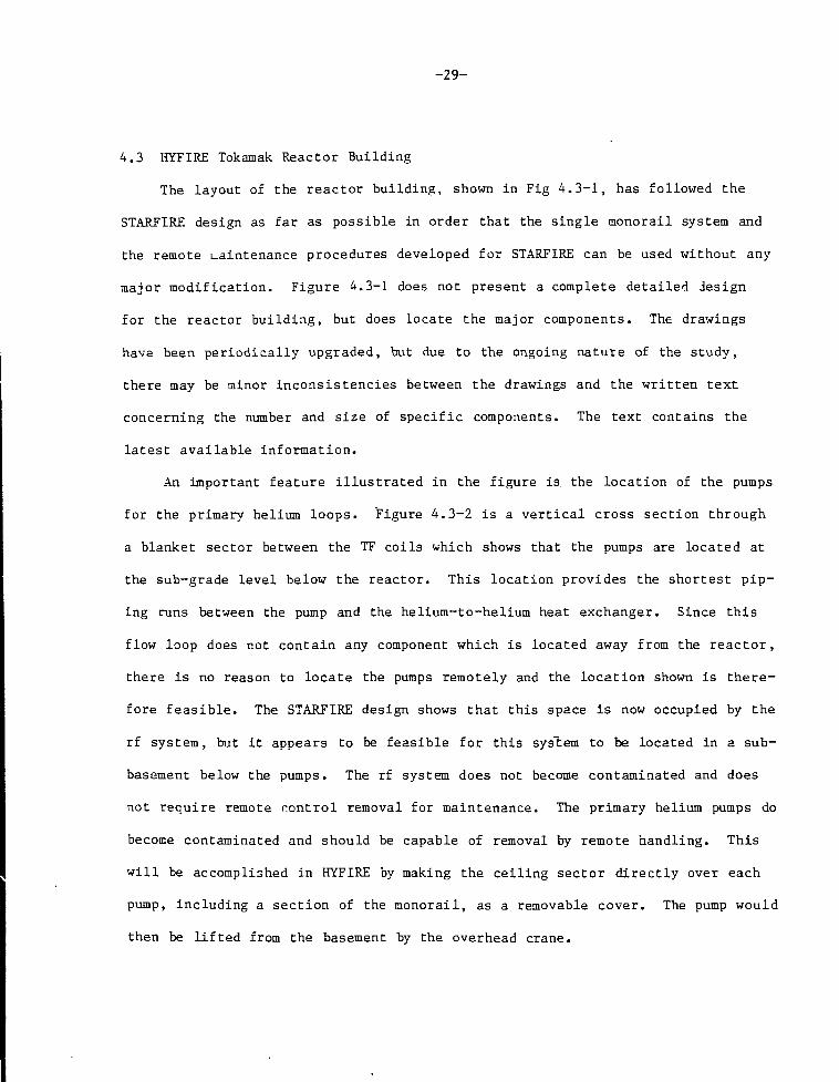
4.3 HYFIRE Tokamak Reactor Building
The layout of the reactor building, shown in Fig 4.3-1, has followed the
STARFIRE design as far as possible in order that the single monorail system and
the remote maintenance procedures developed for STARFIRE can be used without any
major modification. Figure 4.3-1 does not present a complete detailed design
for the reactor building, but does locate the major components. The drawings
have been periodically upgraded, but due to the ongoing nature of the study,
there may be minor inconsistencies between the drawings and the written text
concerning the number and size of specific components. The text contains the
latest available information.
An important feature illustrated in the figure is the location of the pumps
for the primary helium loops. Figure 4.3-2 is a vertical cross section through
a blanket sector between the TF coils which shows that the pumps are located at
the sub-grade level below the reactor. This location provides the shortest pip-
ing runs between the pump and the helium-to-helium heat exchanger. Since this
flow loop does not contain any component which is located away from the reactor,
there is no reason to locate the pumps remotely and the location shown is there-
fore feasible. The STARFIRE design shows that this space is now occupied by the
rf system, but it appears to be feasible for this system to be located in a sub-
basement below the pumps. The rf system does not become contaminated and does
not require remote nontrol removal for maintenance. The primary helium pumps do
become contaminated and should be capable of removal by remote handling. This
will be accomplished in HYFIRE by making the ceiling sector directly over each
pump, including a section of the monorail, as a removable cover. The pump would
then be lifted from the basement by the overhead crane.

- 3 0 -
s
1O
r*
3
aoX
a
3o
«*
OS

- 3 1 -
HTE MODULES-POWER MOOULES
HELIUM TO HELIUMHEAT EXCHANGERS
STEAM PIPE
- — - - v
QUICK DISCONNECTS
PRIMARY HELIUMLOOP PIPES
QUICK DISCONNECTS
SECONDARYHELIUM MANIFOLDS
STEAM MANIFOLDS
PRIMARY HELIUM PUMPS, GEARBOX- MOTOR
FIGURE 4 . 3-2 Hyfirc Tokamak Vertical Section Through Blanket Sector

-32-
Also shown in Figs. 4.3-1 and 4.3-2 are the manifolds for the secondary
helium loop and the high-temperature steam to the electrolyzers. This location
and the design of the piping from the blanket sectors to the manifolds preserves
the STARFIRE monorail concept for removal of a blanket sector from the reactor.
The general layout of the blanket is as much like the STARFIRE commercial
reactor design as possible. The blanket is divided into twenty-eight sectors
with one sector located under the TF coil and the adjacent sector between TF
coils. The blanket sectors are removed horizontally by remote control utilizing
a transport vehicle operating on a hydraulic pad monorail. The vacuum boundary
for the plasma is located at the outside of the shield. The edges of the shield
door are seal-welded to the opening in the vacuum vessel. All of the coolant
lines which penetrate the shield door are permanently welded into the door. The
helium-to-helium heat exchangers are part of the blanket and shie±d door assem-
bly and are moved remotely with the assembly. A single high-temperature helium
pipe and a single low-temperature helium pipe run between each of the fifteen
modules and the fifteen heat exchangers. Groups of five pipes from the heat ex-
changers are manifolded together so that only six primary loop pipes need to be
disconnected to permit the removal of the blanket, shield, and heat exchanger
assembly. A single vertical pipe into and out of the heat exchanger is adequate
for the secondary helium loop because it operates at a higher pressure.
Each of the twenty-eight blanket sectors has its own primary helium n.oop
with its own pump. The activated pumps and piping are located inside the reac-
tor containment. This arrangement also gives the shortest length of piue and
therefore the lowest pumping power for the primary loop. All of the blanket
modules inside a blanket sector are connected in parallel to give a low-pressure
drop. The primary loop flow passes through the still side of the heat exchanger
-33-
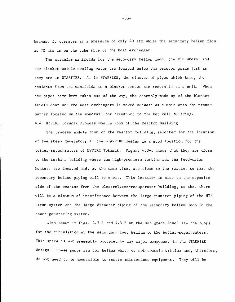
because it operates at a pressure of only 40 atm while the secondary helium flow
at 70 atai is on the tube side of the heat exchanger.
The circular manifolds for the secondary helium loop, the HTE steam, and
the blanket module cooling water are located below the reactor grade just as
they are in STARFIRE. As in STARFIRE, the cluster of pipes which bring the
coolants from the manifolds to a blanket sector are removable as a unit. When
the pipes have been taken out of the way, the assembly made up of the blanket
shield door and the heat exchangers is moved outward as a unit onto the trans-
porter located on the monorail for transport to the hot cell building.
4.4 HYFIRE Tokamak Process Module Room of the Reactor Building
The process module room of the reactor building, selected for the location
of the steam generators in the STARFIRE design is a good location for the
boiler-superheaters of HYFIRE Tokamak. Figure 4.3-1 shows that they are close
to the turbine building where the high-pressure turbine and the feed-water
heaters are located and, at the same time, are close to the reactor so that the
secondary helium piping will be short. This location is also on the opposite
side of the reactor from the electrolyzer-recuperator building, so that there
will be a minimum of interference between the large diameter piping of the HTE
steam system and the large diameter piping of the secondary helium loop in the
power generating system.
Also shown in Figs. 4.3-1 and 4.3-2 at the sub-grade level are the pumps
for the circulation of the secondary loop helium to the boiler-superheaters.
This space is not presently occupied by any major component in the STARFIRE
design. These pumps are for helium which do not contain tritium and, therefore,
do not need to be accessible to remote maintenance equipment. They will be

-34-
moved on air pallets at the subgrade level to a point outside the reactor build-
ing if replacement is necessary.
Since components housed in the process module building are potentially
activated or contaminated, the following items are included as was done in STAR-
FIRE: a) atmospheric tritium process system, b) heating, ventilating and air-
conditioning modules, c) limiter cooling loop module and lay-down work areas.
4.5 HYFIRE Tokamak Electrolyzer Building
The electrolyzer building is located adjacent to the reactor building and
contains the electrolyzers and the recuperators (Fig. 4.3-1). The shape of this
building was changed from the circular design, used in the FY 1981 HYFIRE study,
Ref. 2, to a rectangular shape. This change was made to simplify the construc-
tion and reduce costs. The water-cooled, ceramic insulation-lined, high-
temperature steam pipes cannot be bent but must be manufactured in their final
shape. The circular design would have required the manufacture of curved pipes
of three different radii. In addition, an overhead crane to follow the circular
track would have been expensive. The layout of physical piping in accordance
with the schematic diagram of the FY 1981 report, Fig. 4.5-1, showed that very
little reduction in pipe length would be obtained by a circular arrangement.
Shorter pipe runs were the primary reason for proposing this arrangement in the
first place.
The cross section through the electrolyzer building, in Fig. 4.5-7, shows
that the electrolyzers have been spaced further apart to permit the monorails to
be positioned between '•hem. The electrolyzers will become activated and there-
fore will have to be transported by remote control to the hot cell for disassem-
bly and repair. Figure 4.5-2 shows that the pipe connections to the electro-
lyzers are made with quick disconnects so that a single vertical lift with the

- 3 5 -
FIGURE 4.5-1 Hyfir? Tokamak HTE Steam Piping Schematic Diagram

- 3 6 -
-60-METERS
I I t i •
-LIGHT CRANEFOR REMOVINGPIPE SECTIONS
- — 6LECTROLYZER BUILDINGWALL
,- — ELECTROLYZER
— REMOVABLEPIPE SECTION
QUICK DISCONNECTS{TYPICAL)
STEAM INLETPIPE
/
CLEARANCE SPACEFOR ELECTROLYZEBREMOVAL
MONORAIL L_ STEAM + HYDROGENTRANSPORT OUTLET PIPEVEHICLE
48.00" PIPE TO THEREACTOR MANIFOLD
FIGURE 4. 5-2 End View of the Hyfire Tokamak Electrolyzcr Building

- 3 7 -
overhead crane will separate the pipes from the electrolyzer, and provide an un-
obstructed path for moving the electrolyzer horizontally across a short length
of monorail bridge onto the monorail transporter. The overhead cranes can be
light duty since they do not need to lift heavy electrolyzers. Extensions of
the monorail past the electrolyzers permit the transporter to be used to remove
the recuperators which will also become activated and require remote handling.
The heart of the fusion-driven hydrogen production plant is the bank of
high-temperature, high-pressure steam electrolyzers. These units, which are
based on reversed operation of the Westinghouse developed hydrogen-oxygen puel
cells for direct generation of electricity, take their supply of high-pressure-
superheated steam from the fusion reactor array of steam modules. The ensuing
vapor phase electrolysis generates two products, a heavily steam-laden hydrogen
stream and a dry oxygen stream. Thp.se two product streams transfer part of
their thermal energy via heat recuperators, to the steam exhausted from the
high-pressure turbine which, in turn, is recycled back into the fusion reactor
steam modules. The partially cooled product streams become inputs to two of the
three turbires; the oxygen stream for the oxygen turbine and the heavily steam-
laden hydrogen stream for the low-pressure turbine.
4.6 HYFIRE Tokamak Turbine Building
The turbine building, 100 x 165 m, houses the majority of the turbine plant
equipment. This equipment takes the thermal energy from the two reactor heat
transport streams (pressurized water and helium) and from the hydrogen-steam and
oxygen product streams of the high-temperature electrolyzers, partially converts
this thermal energy into electrical energy, and rejects the remaining energy to
the heat rejection system. The conversion to electrical power is accomplished

- 3 8 -
in three turbine-generators: a high-pressure turbine which operates on super-
heated steam; a low-pressure turbine whose feed is a steam/hydrogen mixture with
a 0.09 mole T^/mole H2O ratio for the HYFIRE Tokamak; and an oxygen turbine.
This is in contrast to the usual designs for fusion reactor-driven electric
power plants, which normally operate only on steam. The equipment involved in
the turbine plant serves the additional role of dewatering the entire hydrogen
output of the high-temperature electrolyzers.
The turbine building houses the three plant turbine-generators. Each of
the turbine generating units is a single 1800 rpm tandem-compound unit coupled
to a hydrogen-inner-cooled synchronous generator. When operating with a 0.90
power factor, the turbine generator set overall thermal efficiency will be about
26%. The principal design/operational characteristics for the three turbines
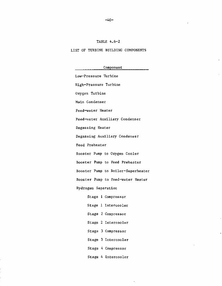
are shown in Table A.6-1, and a l is t of some of the components housed in the
turbine building is found in Table 4.6-2.
The extraction streams of the high- and low-pressure turbines and the ex-
haust from the oxygen turbine provide heating for the boiler-superheater feed
water. Only the low-pressure turbine is coupled to a condenser. The low-
pressure turbine is somewhat non-conventional in that the driving steam is
heavily laden with the gaseous hydrogen product. The oxygen turbine is actually
a conventional gas turbine.
A. Heat Rejection System
This system rejects the heat from the low-pressure turbine main con-
denser, the plant closed loop cooling water system, the hydrogen product post-
compressor after-coolers, the feed-water preheater auxiliary heat exchangers,
the cryogenic systems, the instrumentation and control system, the electrical

-39-
TABLE 4.6-1
HYFIRE TOKAMAK TURBINE PRINCIPLE DESIGN-OPERATION CHARACTERISTICS
Item
Feed Composition
Feed MW Thermal
Feed Temperature, °F
Feed Pressure, psia
Extraction Stages
Exhaust Temperature, °F
Exhaust Pressure, psia
MW Electrical Output
Feed Stream Source
High-PressureTurbine
Tokamak
100% H20
1424
1000
1250
1
759
500
524
Boiler-Superheater
Low-PressureTurbine
Tokamak
H2O-0.09 mole H2
4424
866
497
2
138
2.8
1628
H2-H2ORecuperator
Oxygen Turbine
Tokamak
100% 02
155
1000
497
271
17
57
02Recuperator
- 4 0 -
TABLE 4 . 6 - 2
LIST OF TURBINE BUILDING COMPONENTS
Component
Low-Pressure Turbine
High-Pressure Turbine
Oxygen Turbine
Main Condenser
Feed-water Heater
Feed-water Auxiliary Condenser
Degassing Heater
Degassing Auxiliary Condenser
Feed Preheater
Booster Pump to Oxygen Cooler
Booster Pump to Feed Preheater
Booster Pump to Boiler-Superheater
Booster Pump to Feed-water Heater
Hydrogen Separation
Stage 1 Compressor
Stage 1 Intercooler
Stage 2 Compressor
Stage 2 Intercooler
Stage 3 Compressor
Stage 3 Intercooler
Stage 4 Compressor
Stage 4 Intercooler
-41-
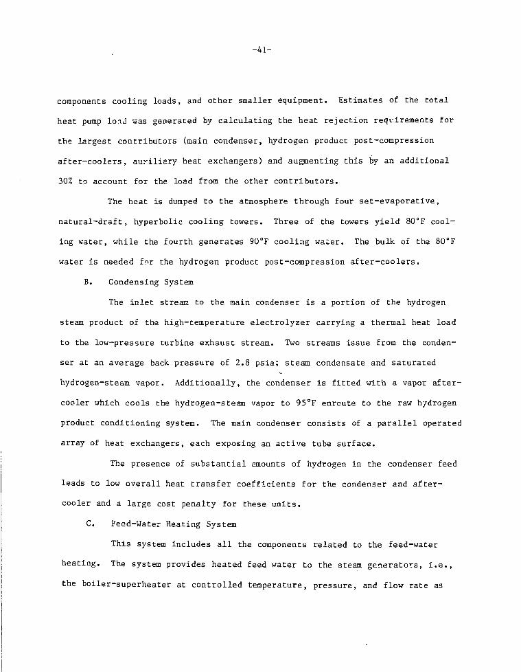
components cooling loads, and other smaller equipment. Estimates of the total
heat pump lond was generated by calculating the heat rejection requirements for
the largest contributors (main condenser, hydrogen product post-compression
after-coolers, auxiliary heat exchangers) and augmenting this by an additional
30% to account for the load from the other contributors.
The heat is dumped to the atmosphere through four set-evaporative,
natural-draft, hyperbolic cooling towers. Three of the towers yield 80°F cool-
ing water, while the fourth generates 90°F cooling water. The bulk of the 80°F
water is needed for the hydrogen product post-compression after-coolers.
B. Condensing System
The inlet stream to the main condenser is a portion of the hydrogen
steam product of the high-temperature electrolyzer carrying a thermal heat load
to the low-pressure turbine exhaust stream. Two streams issue from the conden-
ser at an average back pressure of 2.8 psia; steam condensate and saturated
hydrogen-steam vapor. Additionally, the condenser is fitted with a vapor after-
cooler which cools the hydrogen-steam vapor to 95°F enroute to the raw hydrogen
product conditioning system. The main condenser consists of a parallel operated
array of heat exchangers, each exposing an active tube surface.
The presence of substantial amounts of hydrogen in the condenser feed
leads to low overall heat transfer coefficients for the condenser and after-
cooler and a large cost penalty for these units.
C. Feed-Water Heating System
This system includes all the components related to the feed-water
heating. The system provides heated feed water to the steam generators, i.e.,
the boiler-superheater at controlled temperature, pressure, and flow rate as

- 4 2 -
required to attain optimum efficiency of the high-pressure turbine. Four
sources supply this heat: an extraction stream from the high pressure turbine;
two extraction streams from the high pressure turbine; two extraction streams
from the low-pressure turbine; and finally the exhaust from the oxygen turbine.
The equipment array that comprises the feed-water heating system includes
parallel-operated sets of feed preheaters, degassing heat exchangers, feed-water
heaters, and booster pumps. The feed heater and degassing heat exchangers also
serve to separate the hydrogen from the two extraction stages of the low-
pressure turbines to produce saturated hydrogen-steam vapor. These streams are
dispatched to the raw hydrogen product conditioning system at the appropriate
stage in terms of the hydrogen-to-moisture ratio.
As in the case of the condensing system, the presence of hydrogen in
two of the four heating streams engenders low overall heat transfer coefficients
leading to the required large heat transfer surfaces and concomitantly high
equipment costs.
In addition to the turbine plant piping, valves, supports, and hang-
ers, this system also covers a number of small subsystems and equipment includ-
ing blowdown and turbine plant cooling water.
4.7 HYFIRE Tokamak Hot Cell
The hot cell building shown in Fig. 4.2-1 has been increased in size over
the STARFIRE dimensions in order to accommodate the greater aisle width required
by the larger HYFIRE bl?nket sectors. Quite possibly the building will need to
be further expanded to handle the larger steam generators, the electrolyzers,
and the recuperators which do not exist in the STARFIRE plant. The need for
additional hot cell facilities can be the subject for further studies.

- 4 3 -
4.8 Hydrogen and Water Separation Building
The hydrogen and water separation building is unique to a hydrogen produc-
ing plant. This building requires 40 x 60 m of floor space to house the many
components associated with hydrogen production. Table 4.8-1 l i s t s some of the
installed equipment. One of the major systems involved is the raw hydrogen
product conditioning system.
A. Raw Hydrogen Product Conditioning System
This system includes the installed equipment required for partial
dehydration of the hydrogen product which is accomplished by subjecting the raw
product to eight successive stages of compression and inter-stage cooling. The
equipment involved includes multistage axial compressors, heat exchangers, in-
strumentation, flow split ters and controllers, and piping with various mani-
folds, valves, and. supports.
The feeds to this system are the hydrogen plus water vapor streams
emanating from the feed-water heaters, degassing heaters, and main condensers.
On the average, a compression ratio of 1.73 is used for each of the stages.
After-cooling back to 95°F in each stage is effected by the 80°F plant cooling
water system, with the cooling water flow rate adjusted to control the cooling
water temperature at the point of condensation onset equal to or less than 90°F,
or to a discharge temperature at the after-cooler exit less than 150°F. The
compressions are taken to be polytropic rather than isentropic. with a poly-
tropic factor of 1.36 applied against the specific heat ratio for the H2-H2O va-
por mixtures, and a 95% efficiency is assumed for the compressor drive motors.
A 0.5 psi pressure drop is specified across each of the inter-coolers. Ail of
the condensates are recycled to the feed-water heating system. Four compressors

-44-
TABLE 4.8-1
LIST OF HYDROGEN AND WATER SEPARATION BUILDING COMPONENTS
No. of UnitsComponent HYFIRE Tokamak
Oxygen After-Cooler Cooling Water Circulating Pump 2
Water Feed to Preheater Circulating Pumps 5
Feed Preheaters 4
Desuperheater Condensers for Degassing Heater 4
H2-H2O Vapor After-Cooler 1
Desuperheater Condensers for Feed-Water Heater 7
H2-H2O Vapor Afrer-cooler of Feed-Water Heater 8
Vapor Compressors for Hydrogen Conditioning System (8 stages) 25
Inter-Cooler Condensers for Hydrogen Conditioning System 8
Vapor Compressors for Raw Hydrogen Conditioning and Polishing
(3 stages) 12
Inter-cooler Condensers for Raw Hydrogen Conditioning and Polishing 3

-45-
and one after-cooler are provided for each of the eight stages. The processing
achieves a 0.99 hydrogen mole fraction, corresponding to an end product with a
moisture content of 4.72 wt. %.
B. Hydrogen Product Conditioning and Polishing
Another group of components required is the hydrogen product condi-
tioning and polishing equipment. This includes the components associated with
treating the end stream of the raw hydrogen product conditioning system to
transform it into bone-dry decontaminated hydrogen which is the end product of
the fusion driven synfuel plant. The processing operations involved to achieve
these results include: 1) three additional stages of compression with after-
cooling to 85°F; 2) high-pressure scrubbing in water to trap any residual radio-
activity; 3) desiccating the hydrogen by means of molecular sieves; and 4) con-
centrating the radioactivity picked up by th° scrub water by multiple effect
evaporation, followed by dispatching the concentrate to the plant radwaste
facility for ultimate disposal.
The principal equipment needed to achieve the described processing in-
cludes: twelve compressors; three after-coolers; one scrubbing tower; two scrub
water circulating pumps; three molecular sieve desiccating columns; one triple
effect evaporator operated in the forward flow mode; instrumentation and con-
trols; and an array of piping with valves and supports.
4.9 HYFIRE Tokamak Tritium Reprocessing and Cryogenic Building
The HYFIRE Tokamak tritium reprocessing and cryogenic building is the same
as was reported in Ref. 2 and is shown here for facility completeness.
Figures 4.9-1 and 4.9-2 show the ground level and upper level plans and
Fig. 4.9-3 shows the elevation, respectively, for this building. The components
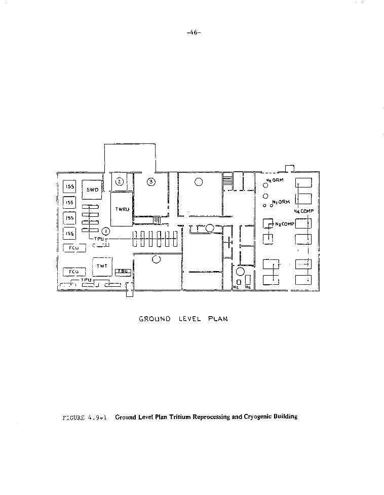
- 4 6 -
GROUND LEVEL PLAM
FIGURE 4 . 9 T 1 Ground Level Plan Tritium Reprocessing and Cryogenic Building

- 4 7 -
METM ACCESS PLATFORM
ISS
ISS
TPU
OPEN
- i OI'tM
^ = ' .
ED
—M *HUl AHU!
MO
APTS APTS
D
APTS ATPS
UPPER LEVEL PLAN
FIGURE 4. 9-2 Upper Level Plan Tritium Reprocessing and Cryogenic Building

- 4 8 -
n
FIGURE 4. 9-3 Elevation Cross Section of the Tritium Reprocessing and Cryogenic Building

-49-
are arranged in the building essentially as shown in the STARFIRE report (Ref.
1) Figure 20-11. The HYFIRE Tokamak components will require more space because
of the larger amount of tritium handled and stored. STARFIRE is a 4000 MW(th)
unit while HYFIRE Tokamak is 6000 MW(th), and the tritium burnup in STARFIRE is
42% while it is only 35% in HYFIRE Tokamak. Accordingly, the ratio of tritium
fuel/day used by the HYFIRE Tokamak compared to STARFIRE is:
6000 x 0.42 = fi
4000 x 0.35
It is estimated that the space requirements for HYFIRE's tritium handling
units would on the average have (1.8)2/3 = 1.48 larger cross section than
those for STARFIRE, so a linear factor of (1.8) 1/ 3 = 1.22 applies. This scal-
ing does not apply for the tritium storage units which for HYFIRE Tokamak would
be based on about 10+ days of capability compared with less than one for STAR-
FIRE. Here a factor of approximately [(6000 x 0.42/4000 x 0.35) x (10)]0.333
= 2.6 is applied on the height. The dimension requirements for individual com-
ponents based on Table 14.3 of the STARFIRE report become those shown in Table
4.9-1. These are the dimensions used for the components in Fig. 4.9-1.
The HYFIRE building dimensions for the tritium processing area were scaled
up also by approximately the 1.22 linear factor. The operations control and
cryogenics area which should not change with the tritium volume handled was re-
tained at a width of 40 m to give an overall building length of 80 m.
4.10 Electrical and rf Power Supply Building
In the HYFIRE Tokamak site plan of Fig. 4.2-1, the area has been doubled
over that shown for STARFIRE in Fig. 4.1-1. The area required for the rf power
supplies is increased in proportion to the increase in thermal output from 4000
to 6000 MW(th). An equal area is alloted to the rectifiers which provide direct
current to the rectifiers, a component which was not required in STARFIRE.

- 5 0 -
TABLE 4 . 9 - 1
DIMENSIONS OF TRITIUM HANDLING COMPONENTS DERIVED FROMSTARFIRE REPORT TABLE 1 4 - 3
STARFIRE D i m e n s i o n s EYFIRE TOKAMAK Dimens ion
Component
Atmospheric T Recovery
Units (ATR)
Isotope Separation System
Fuel Cleanup Unit (FCU)
T Waste Treatment (TWT)
Solid Waste Disposal (SWD)
Transfer Pump Unit (TPU)
T Storage (TS)
Tritiated Water RecoveryUnit (TWRU)
Fuel Blender Unit (FBU)
m
6.25x8x5
(1 unit)
3x3x12
6x2x2
5x5x5
5x5x4
4x1x2
8x4x2
6x9x3
4x1x2
3m
2500
(10 units)
108
24
125
100
8
64
162
8
m
7x9x5
4x4x12
7x2.5x2
6x6x5
6x6x4
5x1x2
8x4x5
7x11x3
5x2x2
3m
3150
(10 units)
192
35
180
144
10
160
231
20
-51-
4.11 Heat Rejection System
The heat rejection system rejects the heat from the low-pressure turbine
main condenser, the plant closed loop cooling water system, the hydrogen product
post-compressor after-coolers, the feed-water preheater auxiliary heat exchang-
ers, the cryogenic systems, the instrumentation and control system, the electri-
cal components cooling loads, and other smaller equipment. Estimation of the
total heat dump load was generated by calculating the heat rejection require-
ments for the largest contributors (main condenser, hydrogen product post-
compression after-coolers, auxiliary heat exchangers) and augmenting this by an
additional 30% to account for the loads from the other contributors.
The heat is dumped to the atmosphere through four wet--evaporative, natural-
draft, hyperbolic cooling towers. Three of the towers yield 80°F cooling water,
while the fourth generated 90°F cooling water. The bulk of the 80°F water is
needed for the hydrogen product post-compression after-coolers.
Table 4.11-1 lists the main parameters and equipment for the heat rejection
system.

-52-
TABLE 4.11-1
PRINCIPAL PARAMETERS FOR THE HEAT REJECTION SYSTEM
Item HYFIRE Tokamak
80°F System Cooling Towers
Mean Inlet Temperature, °F 123Heat Dump, MW 4190Design Flow Rate, gpm 768,000
90°F System (1 Cooling Tower)
Mean Inlet Temperature, °F 102Heat Dump, MW 303Design Flow Rate, gpm 175,000

-53-
5. COSTING ANALYSIS
5.1 General
The cost of producing hydrogen using a fusion reactor as the basic heat
source involves the utilization of various source materials. Since the STARFIRE
Study (Ref. 1) performed a very detailed analysis of the overall cost for a
power producing Tokamak fusion reactor, it was used as the starting basis for
the determination of the majority of the costs associated with the reactor plant
equipment, balance-of-plant equipment, land, and other related structures and
site facilities. The basic information was modified as required to adapt it to
a hydrogen producing plant with a 50% increase in thermal power. The items
which were not modified were updated by applying an escalation factor to account
for the changes from 1980 to 1981 costs.
The STARFIRE and HYFIRE studies used the DOE guidelines which were outlined
in Refs. 2 and 3. All estimated costs in this report are September 1981 dollars
unless stated otherwise.
It was necessary to make specific assumptions and to scale the cost data to
account for the major change of the HYFIRE-Tokamak reactor generating 6000
MW(th) as opposed to STARFIRE generating 3500 MW(th). The two reactors are very
simmilar with the main differences being in the overall size and the blanket
configurations.
Many of the components in the HYFIRE plants are not found in STARFIRE be-
cause they are unique to the hydrogen production plant, e.g., the electrolyr:ers
and the hydrogen conditioning components. The latter includes components such
as vapor compressors, intercooler condensers, scrubbing towers, recuperators,
etc. These components were sized as required by the process flow sheet and cost

-54-
estimates made. As the study progressed, additional information became avail-
able which resulted in some components being re-estimated and/or moved to dif-
ferent account numbers. Since it was not feasible to revise all the original
work, there may be slight numerical inconsistencies between this Section and
Appendix C which have no effect on the final information appearing in Capital
Cost Summary Tables 5.3-1 and 5.3-2. These cost models followed the basic con-
siderations which were used in the development of the COAST code. Since these
original calculations, made for individual components required for the hydrogen
production, were limited to the bare pieces of Equipment, it was necessary to
provide the proper adders to arrive at the "installed component cost." The fol-
lowing are considered necessary ingredients to provide "as installed cost" data:
A. Installation, labor, foundations, supports, platforms, construction
expenses, etc;
B. Piping, valves, fittings, supports;
C. Electrical: power, lighting, instrument wiring;
D. Engineering: design, supervision, testing and checkout, overhead,
drafting, QA, purchasing, reproductions, etc.;
E. Shipping and transportation;
F. Administration;
G. Contractor and installer fee; and
H. Insulation.
In the absence of rather detailed equipment layouts, exact piping sizes,
and limited time for in-depth evaluation, making estimates for the above adders
is difficult. Some guidance for making these estimates is furnished by Peters
and Timmerhaus.^' The above adder items were individually evaluated for
-55-
each component and cost estimated. These adder costs have beeu summarized in
Table 5.1-1 for the HYFIRE Tokamak components.Since the plant is considered to
be the "tenth-of-a-kind for a specific design technology," the adder percentages
were not consistently used for each component. Judgment was utilized in order
that undue adders would not be incorporated. As an example the "Engineering and
Design" factor actually used ranged from less than 1.0 to 22% of the base com-
ponent cost.
5.2 Hydrogen Producing Components for HYFIRE
There are a large number of components in the hydrogen production plant
that had to be costed. This is evident from the flow sheet in Section 3. The
costing of each component was based on a design of each component. The designs
and sizing of the components were developed from the state points given in the
flow sheet. The cost determinator differs depending on the specific type of
component involved. The cost algorithms used are discussed in Appendix C. As
an example, the cost determinator for evaporators, heat exchangers, and conden-
sers is the square feet of heat transfer surface area and the design pressure.
The cost determinators for compressors are brake horsepower and the design pres-
sure, while for pumps it is gallons per minute.
The sizing of the components was based on common engineering practice and
engineering experience. For example, heat exchangers were sized based on the
amount of heat transferred, approximate heat transfer coefficients, and log mean
temperature differences. Individual components associated with the synfuel
plant are discussed in Appendix C and any special conditions are described
therein. However, the details of the calculations are not given.
Since some of the components would be excessively large in a single unit,
one or more units were specified based on the ratings of commercially available

-56-
TABLE 5 .1 -1
Summary Cost Adders for Hyfire Tokam:
NO. OF UNITS
420
28
28
8
20
1
12
15
2
5
6
5
4
4
1
7
2
161
25
812
31
13
4
28
ITEM
He-He HEAT EXCHANGER
PRIM. He CIRC. COMPRESSOR
SEC. He CIRC. COMPRESSOR
0 2 REGEN.COOLER
H 2 RECUPERATOR
0 2 RECUPERATOR
BOILER SUPERHEATERS
FIRST WALL H2O CIRC. PUMP
0 2 AFTER-COOLER CIRC. PUMP
FEED PREHEAT. CIRC. PUMP
BOILER SUPERHEAT. CIRC. PUMP
MAKE-UP H20 CIRC. PUMP
FEED PREHEATER
DEGASSING HEAT EXCHANGER
DEGAS. HEATER VAPOR AFT. COOLER
FEED WATER HEATER
FEED WATER HEATER VAPOR AFT. COOLER
MAIN CONDENSER
MAIN COND. VAPOR AFT. CL.
VAPOR COMPRESSOR (STAGES 1-8)
INTERCOOLER (STAGES 1-8)PRODUCT COND. COMP (STAGES 9-11)
INTERCOOLERS (STAGES 9-11)
H2 SCRUBBING TOWER,
PUMPS AND PALL RINGS
SCRUB WATER EVAPORATOR
DRYING TOWERS,MOLECULAR
SIEVE (RESIN) AND AUXILIARIES
PLANT COOLING WATER SYST.
HIGH TEMP. ELECTROLYZER
BARE EQUIPMENTCOST
121.79
4126
22.67
1.88
166.40
5.54
202.50
4550.157
14)21
1.42
0.43235.80
6.32
0.17234577
2.758
60.02
0.172
16.81625.88811215
21.823
3.122
1.373
10.304
68.13
208.90
INSTALLATION
24.358
8250
4.534
0.376
3.328
1.107
40.500
0.871
0.031
0204
0.285
0.086
7.161.384
0.035
4.915
0.552
12.004
0.034
3.364
5.1782.243
4.365
0.624
0275
2.066
13.626
41.780
PIPING
60.895
20.630
11.335
0.940
83200
D.5E4
101.250
2.177
0.078
0.511
0.713
0.216
17.930
3.46C
0.088
12.289
1.379
30.010
0.086
8.40912.944
5.608
10.912
1.479
0.687
4228
34.065
104.4F
INSULATION
-
-
0.150
13.312
0.443
16200
0.348-
0.082
0.114—
2.864
0.554
0.014
1.966_
4.802_ •
—
-_
_
_
0.110_
—
16.710

-56-
TABLE 5.1-1
I Adders for Hyfire Tokamak Components (SM)
K G
•95•30•35Ko•00
•so• "mnn iH 3
•16•DOKoK• 9B 9Hio• sB»K4
ft8• z
r• 5
L
INSULATION
-
-
0.1 SO
13.312
0.443
16200
0.348-
0.082
0.114-
2.864
0.554
0.014
1.966-
4.802- •
-
-
-
-
—
0.110
—
-
16.710
SHIPPING
2.535
0.825
0.453
0.038
3.521
0.055
4.0500.087
0.003
0.020
0.029
0.003
0.716
0.1380.004
0.492
0.055
1200
0.003
0.336
0.5180.224
0.436
0.062
0.027
0.207
1.636
4.18
ELECTRICAL
2.888
1.587
-
-
-
-
0.305
0.011
0.071
0.100
0.030-
—
—
—
—
-
-
1.177
-
0.7G5
-
0.003
0.096
0.578
4.7G9
14.62
ENGINEERING
0.128
0.234
0.178
0.052
1.830
0.277
3.712
0.128
0.017
0.045
0.063
0.019
1569
0.381
0.039
0.077
0.303
0.8250.038
0.462
5.695
0.822
4.801
0.646
0.302
0.648
4.996
2.099
ADMINISTRATION
0.023
0.059
0.032
0.009
0.3330.221
0.675
0.012
0.003
0.008
0.011
0.003
0.358
0.069
0.007
0.140
0.055
0.150
0.007
0.084
1.036
0.150
0.873
0.118
, 0.055
0.118
0.908
0.840
CONTRACT FEE
7.307
2.476
1.360
0.1139.984
0.33212.150
0.261
0.009
0.061
0.086
0.026
2.148
0.415
0.011
1.480
0.165
3.60
0.010
1.009
1.553
0.673
1.309
0.187
0.082
0.620
4.088
12.530
TOTAL INSTALLEDCOST
217.04
76.71
42.15
3.56311.67
3.56381.04
8.54
0.31
2.02
2.83
0.82
68.92
13.22
0.37
46.13
5.27
112.61
0.53
31.66
52.81
21.72
44.52
6.71
3.01
18.80
68.17
406.09

-57-
equipment. Because there are cost savings in the manufacture and purchase of
multiple units, discounts va the total cost of 5, 10, ar.d 15% are taken for two,
three, and four units, respectively.
The size of the components, number of units of e<~h type, the scaling para-
meters, scale and cost coefficients, and the total cost (of one or more units)
are sunim_rized in Table 5.2-1.
Note that the hydrogen production components primarily affect Cost Account
22 (Reactor Plant Equipment) and Account 23 (Turbine Plant Equipment). The
basic costing algorithm is given by the equation
a a a a a aCost/Unit = $C QY O(A)
L (P) L (B) J (W) 4 (M) 3 (0) "
where Co is the cost coefficient, Yo, is a multiplicative factor, <*i, Q-z,
a3, ak, a5, and «6 are scale factors. The variables in parentheses are the
scaling parameters. A is the external heat transfer surface area, P is the com-
ponent design pressure, B is the brake horsepower, W is the flow rate in gpm, M
is the mass of the unit, and 0 is the power output. This equation is applicable
to essentially all types of equipment, depending on the value of the scale
factors specified. Fo" example, for heat exchangers, ^3, <*4, <*5, and ^6 are
zeros and Yo = 1, thus the costing algorithm reduces to
ai a2Cost/Unit = $C (A) (P)
0
5.3 Capital Cost Account
A. Cost Accounting Format
The DOE guideline for the cost accounting format provided in Ref. 2
was used for the HYFIRE study. STARFIRE^1) costs were developed from this

TABLESUMMARY OF COMPONENT DESIGN PARAMETERS, COST COEFFICII
Cost/Unit = SC070 (A) a 1 ( P ) a 2
Account
22.02.01
22.02.02
22.02.03
22.02.04
22JD2.05
22.02.06
23.01
23.03.01
23.03.02
23.04.01
23.04.02
23.05.01
23.05.02
23.05.03
23.05.04
23.05.05
23.05.06
Item
Primary to Secondary HeliumHeat Exchangers
Primary Helium CirculatingCompressors
Secondary Helium CirculatingCompresses
Oxygen Regenerative Coolers
Bailer Superheaters
Pressurized Water CirculatingPumps
Turbine Generator* - O2 Turbine- High Pressure Turbine- Low Pressure Turoine
Plant Cooling Water Heat Dump System80°F System90°F System
Water Rearculating Pump
Main Condensers
H 2 0-H 2 Vapor After-Cooler
far Main Condensers
Oxygen AftEr Cooler, CoolingWater Pumps
Circulating Pumps for WaterFeed-to-Feed Preheater
Circulating Pumps far WaterFeed-to-Boiler Preheater
Circulating Pumps for Make-Upand Recycle Water
Feed Preheaters
Desuperheater-Ccndenser forDegassing Unit
Numberof Units
420
28
28
8
12
13
31
8
16
25
3
3
6
5
4
4
OverallDimensions
(Space Req'd)ft. O.D. xft. long
1.33x11.67
B.3 x 9.9
6.1 x 7.4
3.1 x 12.8
11.6x42.2
9.2x13.7
10.42 x 61.08
3.79 x 13.5
3.6x5.3
9.2x13.2
9.2x132
9 2 x 1 3 2
725 x 67.75
9.17x45.5
AExternal
Heat TransferSurface
ft2
820
3.818
6.4 x 10 4
174,840
3.770
150230
98.530
PDesign
Pressurepsia
1030
720
1570
line
4350
4380
30
30
1130
1130
1900
60
1130
60
BBrake
Horsepower,BHP
9,000
510
890
12,650 :
12.650
12,650 :
'Component Hardware Costs Only

-58-
• COEFFICIENTS, SCALE FACTORS AND COSTS FOR THE HYFIRE (TOKAMAK)i ( f l )
K1,P,a2.B.a3(W)a4(M)aS(O)a6
: Bj BrakelorapowK,| BHP
I
) 9.00D
: 510
890
12,650
12,650
12.650
WFJownrte
GPM
12.000
2.17 x 10*2.73 x 10s
700
12,000
12,000
12,000
MM a s ,
Ib
QTurbineOutput,
MW
109.7497155.6
CoCost
Coefficient
49S
1800
245.8
602.6
1136
1100
5.56 x 1 0 4
5.56 x 10*5.56 x 1 0 4
755.8493.5
1098.0
568.2
310
1100
1100
1100
1100
516.5
310
0.646
0
0
0.473
0.640
0
000
00
0
0.646
0.646
0
0
0
0
0.646
0.646
0.293
0
0293
0.293
0.293
0293
000
00
0
0293
0.293
0.293
0293
0.293
0293
0293
0.233
a3
0
0.733
0.723
0
0
0
0
0
0
00
0.337
0
0
0
0
0
0
0
0
«4
0
0
0
0
0
0.337
000
00
0
0
0
0.337
0.337
0.337
0.337
0
0
0
0
0
0
0
0
0
0
0
0.820.82
0
0
0
0
0
0
0
0
0
a 6
0.E
0.6
0.6
?0
1
1
1
1
1
1
1
1
1
1
0.01
1
1
1
Total *Cost
(one ormore units)
S M
121.8
41.3
22.7
1.88
202.5
4.55
1.0
2.30
1.15
53.8
1420.12
60.02
0.17
023
1.02
1.43
0.43
35.8
6.92

- 5 9 - f
TABLE 5 .2 -1 (CONTINUED)SUMMARY OF COMPONENT DESIGN PARAMETERS, COST COEFFICIENTS, SCALE
Cost/Unit = SCQ70 (A ) * 1 If)^ (B ) " 3 (W)"4 (1
Account
23.05.07
23.05.08
23.05.09
23J1B.01
23.08.02
23.08.03
23.08.04
23.08.05
23.08.06
23.08.07
23.08.08
Item
H.O-Hj Vapor After-Cooler
of the Qegassing. HeatErs
Desuperheater-Condenser lorFeedwater Heater
H J O - H J Vapor After-Cooler
of the Feedwater Heater
Vapor Compressor for H j
Conditioning System, Stages 1-8
Intercooier-Condenser forHydrogen Conditioning System,Stages 1-8
Vapor Compressors for Raw H2Product Conditioning-PolishingStages 9-11
IntEftsolei-Condenser for Raw H2OProduct Conditioning-Polishing,Stages 9-11
Raw Hydrogen Product Scrubbing TowerScrub Tower and Motor PumpsScrub Tower Pall Rings
Scrub Water Evaporator
Drying Towers
High Temperature ElectrolyzerMolecular Sieves (Resin)Drying Tower Auxiliaries
Numberof Units
1
7
7
25
8
12
• j
12
1
3
28
Z
OverallDimensions
(Space Req'd)ft. O.O. xft. long
3J6 x 19.92
9.17x60.83
7.83 x 42.75
9.1 x 47
8 x 3 0
9.1 x 47
19.7x64
AExternal
I.eat T-ansferSurface,
ft.2
3.400
133.400
69,360
26,330
2,478
POesijn
Pressurepsii
60
60
60
220
Varies withthe stage(380-1150)
1150
1150
1150
BBrake
HorsepowerBHP
Varies with
the stage
Varies with
the stage
0.53
WFlownte
GPM
714.6
'Component Hardware Costs Only
A = External hsat transfer surface area, ft
P - Design pressure, psia
B = Brake horsepower, HP
W -- Flownte, gpm
M = Mass, Ib
P - Varies from stage to stage

-59 -
5 . 2 - 1 (CONTINUED)COEFFICIENTS, SCALE FACTORS AND COSTS FOR THE HYFIRE (TOKAMAK.)h"* n** W*3 m"* m"* M**
• BBakeepowr,
•8HP
K with
jstig.
its with•Up
0.53
WFlawnte
GPM
714.Q
MMass,
Ib
1.76 x i O 5
1.76 x 10⁵
1.76 x i O 5
QTurbineOutput,
MW
CoCost
Coefficient
250
516.S
310
1860
206.6
1860
206.6/3
173.14447
17,570
173.1
173.1
a 1
0.646
0.646
0.646
0
0.646
0
0.646
0
0
0.649
0
0
<*2
0.293
0.293
0.293
0
0.293
0
0.293
0.293
0J293
0
0.292
0793
a3
0
0
0
0.733
0
0.733
0
0
0.78
0
0
0
a 4
0
0
0
0
0
0
0
0
0
01
0
0
as
0
0
0
0
0
0
0
0.630
0
0.63
0.63
a6 TO
1
1
1
1
1
1
11
1
1
0.07
Total *Cost
(one ormore units)
$ M
0.17
24.6
2.76
16.82
25.82
11.22
21.82
2.920.040.16
1.37
8.26
216.441.850.93
-60-
foraat. Even though all the assumptions being made by individual study groups
are not identical, comparisons of some of the results can be made as long as
logical judgment is used.
B. Capital Cost for HYFIRE Tokamak
The total capital cost for HYFIRE is shown in Table 5.3-1. This table
was developed using STARFIRE Table 22-5, Ref. 6 (which is included in this re-
port as Table 5.3-1) as its base. (Tables 5.3-1, 5.3-2, 5.3-3, 5.3-4, and 5.3-5
appear at the end of Section 5.) An estimate was developed for each applicable
account number entry. Specific accounts, as noted below, used in STARFIRE are
estimated costs with the only change being the escalation of 5% for one year
from the 1980 STARFIRE to the 1981 costs for the HYFIRE Tokamak. These accounts
are:
Account 20 (Land and Land Rights), 21 (Structures and Site Facilities)
except for the reactor building, hot cell building, electrolyzer building, pro-
cess module building and hydrogen water separation building, 24 (Electric-Plant
Equipment), 25 (Miscellaneous Plant Equipment), and 26 (Special Materials).
Account 22.01 (Reactor Equipment) utilized the STARFIRE costs with
modification factors of 1.5 and 2.55 used to account for the different sizes,
special materials, and operating conditions. As an example, the STARFIRE
blanket and first wall cost of $82.36 M was raised to $210 M for HYFIRE. The
STARFIRE Magnet cost of $171.57 M was raised to $257.36 M.
Accounts 22.02 (Main Heat Transfer and Transport Systems), 23.08
(Hydrogen Conditioning System), 22.07 and 23.07 (Instrumentation and Control
Equipment) were developed independently for HYFIRE.
The total direct cost for the plant including construction of $540 M
($2124 M - STARFIRE) and the total capital cost is $6108 M ($2400 M - STARFIRE)
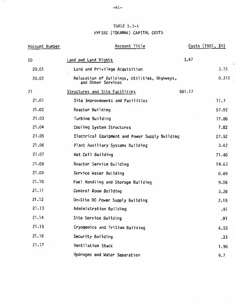
-61-
TABLE 5.3-1
HYFIRE (TOKAMAK) CAPITAL COSTS
Account Number Account Title Costs (1981, $M)
20 Land and Land Rights 3.47
20.01 Land and Privilege Acquisition 3.15
20.02 Relocation of Buildings, Utilities, Highways, 0.315
and Other Services
21 Structures and Site Fac i l i t ies 501.17
21.01 Site Improvements and Fac i l i t i es 11.7
21.02 Reactor Building 57.92
21.03 Turbine Building 77.80
21.04 Cooling System Structures 7.82
21.05 Electrical Equipment and Power Supply Building 27.52
21.06 Plant Auxi l iary Systems Building 3.4221.07 Hot Cell Building 71.40
21.08 Reactor Service Building 19.63
21.09 Service Water Building 0.69
21.10 Fuel Handling and Storage Building 9.06
21.11 Control Room Building 3.26
21.12 On-Site DC Power Supply Building 2.15
21.13 Administration Building .91
21.14 Site Service Building .91
21.15 Cryogenics and Tritium Building 6.53
21.16 Security Building .33
21-17 Ventilation Stack 1.90
Hydrogen and Water Separation 9.7

-62-
Account Number
27.
21.90
21.99
22.01
22.01.01
22.01.02
22.01.03
22.01.04
22.01.05
22.01.06
22.01.07
22.01.08
22.01.09
22.02
TABLE 5.3-1 (Cont'd)
Account Title
Electrolyzer Building
Process Module Building
Spare Parts Allowance 2%
Contingency Allowance
Reactor Plant Equipment
Reactor Equipment
First Wall and Blanket
Shield
Magnets
RF Heating and Current Drive
Primary Structure and Support
Reactor Vacuum
Power Supply, Switching and Energy Storage
Impurity Control
ECRH Plasma Breakdown
Main Heat Transfer and Transport Systems
Helium Heat Exchangers
Primary Helium Circulating Pumps
Secondary Helium Circulating pump
Oxygen After-Cooler
Recuperator H2O-H2 Units
Oxygen Recuperator
Boiler Superheater
8oiler Superheater Feed Pumps
Costs (1981, 5M)
103.66
31.17
u.yn
44.75
2218.59
1186.39
851.48
210.02
47;.48
257.36
50.24
79.11
12.39
79.35
6.25
7.19
217.04
76.71
30.82
2.85
228.47
7.98
279.79
1.50

-63-
TABLE 5.3-1 (Cont'd)
Account Number Account Title Costs (1981, S.M)
First Wall Pressurized H2O Circ. Pump 6.36
22.03 Cryogenic Cooling System 22.35
22.03.01 Helium Liquifier Refrigerator 11.55
22.03.02 LHe Transfer and Storage 5.4
22.03.03 He Gas Storage 4.2
22.03.04 LN2 System 1.2
22.04 Radioactive Waste Treatment and Disposal 7.2
22.02.01 Liquid Waste Processing and Equipment 2.55
22.04.02 Gaseous Wastes and Off-Gas Processing System 2.7
22.04.03 Solid Wastes Processing Equipment 1.95
22.05 Fuel Handling and Storage Systems 64.93
22.05.01 Secondary Processing - Off Gas Treatment 7.85
22.05.01 Isotope Purification (Cryogenic 10.18Distillation)
22.05.02 Plasma Exhaust Processing 7.85
22.05.02 Processing Atmospheres Detritiation 3.12
22.05.03 Fuel Preparation 0.45
22.05.04 Fuel Injection 1.50
22.05.05 Tritium Storage 6.73
22.05.05 Deuterium Storage 2.48
22.05.06 Bred Tritium Extraction 10.90
22.05.07 Reactor Vessel Detritiation Unit 2.13
22.05.07 Reactor Hall Atmosphere Detritiation Unit 11.74
22.06 Other Reactor Plant Equipment 51.22
22.06.01 Maintenance Equipment 43.00
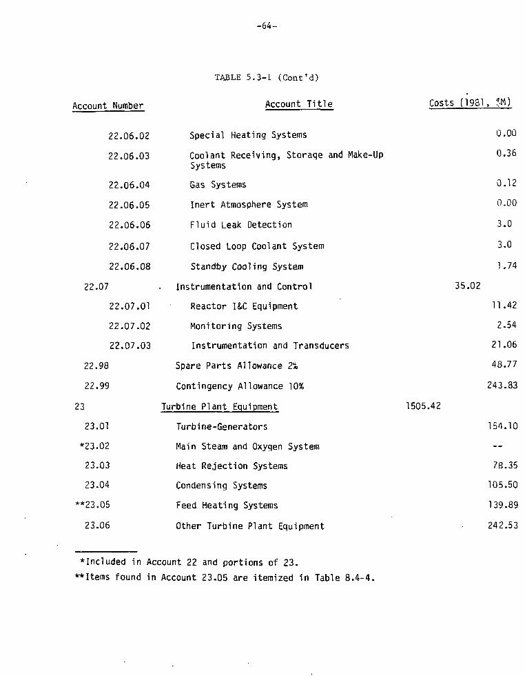
-64-
TABLE 5.3-1 (Cont'd)
Account Number Account Title Costs (1931, $
Special Heating Systems 0-00
Coolant Receiving, Storage and Make-Up 0«36Systems
Gas Systems 0.12
Inert Atmosphere System 0.00
Fluid Leak Detection 3.0
Closed Loop Coolant System 3.0
Standby Cooling System 1.74
Instrumentation and Control 35.02
Reactor I&C Equipment 11.42
Monitoring Systems 2.54
Instrumentation and Transducers 21.06
Spare Parts Allowance 2% 48.77
Contingency Allowance 10% 243.83
Turbine Plant Equipment 1505.42
Turbine-Generators 154.10
Main Steam and Oxygen System
Heat Rejection Systems 78.35
Condensing Systems 105.50
Feed Heating Systems 139.89
Other Turbine Plant Equipment • 242.53
•Included in Account 22 and portions of 23.
**Items found in Account 23.05 are itemized in Table 8.4-4.
22
22
22
23
23
*23
23
23
**23
23
22.06.
22
22
22
22
22
22
.07
22
22
22
.98
.99
.01
.02
.03
.04
.05
.06
.06.
.02
.03
.06.04
.06,
.06
.06,
.05
.06
.07
.06.08
.07
.07
.07
.01
.02
.03

- 6 5 -
TABLE 5.3-1 (Cont'd)
Account Number Account T i t l e Costs (1981, $M)
Instrumentation and Control (I&C) Equipment 35.04
Hydrogen Conditioning System 588.72
H2-H2O Vapor Compressors (Stages 1-8) 23.25
Post Compression After-Coolers (Stages 1-8) 39.87
Piping, Valves, Supports, e tc . 21.35
H2-H2C Vapor Compressors for Raw 22.51Hydrogen Product (Stages 9-11)
Post Compression After-Coolers (Stages 9-11) 46.05
Scrubbing Tower Canned Pumps and Pall . 6.71Rings for Raw Hydrogen Product
Evaporator for Deactivating Scrub Water 3.10
Final Hydrogen Product Drying Tower and 19.79Molecular Sieve Auxil iaries
Electrolyzer 406.09
Spare Parts Allowance 2% 26.88
Contingency Allowance 10% 134.41
Electric Plant Equipment 118.67
Switchgear 13.0
Station Service Equipment 17.89
Switchboards 8.19
Protective Equipment 2.22
Electrical Structures and Wiring Containers 18.27
Power and Control Wiring 37.79
Electrical Lighting 8.61
*Not included in normal account number system.
23,
*23,
23
23
24
24
24
24
24
24
24
24
.07
.08
23
23
23
23
23
23
23
23
23
.98
.99
.01
.02
.03
.04
.05
.06
.07
.08
.08
.08
.08
.08
.01
.02
.03
.04
.05
.08.06
.08
.08
.08
.07
.08
.09

-66-
TABLE 5.3-1 (Cont'd)
Account Title Costs (1981, $H)
Spare Parts Allowance 4% 2.12
Contingency Allowance 10% 10.60
Miscellaneous Plant Equipment 46.19
Transportation and Lifting Equipment 20.24
Air and Water Service Systems 12-97
Correnunications Equipment 6.53
Furnishing and Fixtures 0.78
Spare Parts Allowance 3% 1-62
Contingency Allowance 10% 4.05
Special Materials 0.25
TOTAL DIRECT COST
Construction Facilities, Equipment andServices (10%)
Engineering and Construction ManagementServices (8%)
Other Costs - Owners (5%)
SUBTOTAL 5404.33
1981 1987Constant Then-Current
94 Interest During Construction 704.18 1709.39
95 Escalation During Construction 0.00 1024.66
TOTAL CAPITAL 6108.51 8138.38
$/#H2 .66 1.27
$/MBtu H2 10.74 20.88
Account Number
24
24
25
25
25
25
25
25
25
26
91
92
93
.98
.99
.01
.02
.03
.04
.98
.99
4393
439
351
219
.76
.38
.50
.69

- 6 7 -
TABLE 5.3-2HYFIRE (TOKAMAK) CAPITAL COSTS
(ABBREVIATED)
Account Number Account T i t l e Costs (1931, $M)
?O Land and Land R igh ts • 3.47
20.01 Land and Pr iv i lege Acquisi t ion 3.15
20.02 Relocation of Buildings, U t i l i t i e s , Highways, 0.3113and Other Services
21 Structures and Site Fac i l i t i es 447.48
21.01 Site Improvements and F a c i l i t i e s 11.7
21.02 Reactor Bui lding 57.92
21.03 Turbine Bui lding 77.80
21.04 Cooling System Structures 7.82
21.05 Electr ical Equipment and Power Supply Building 27.52
21.06 Plant Aux i l ia ry Systems Bui ld ing 3.42
21.07 Hot Cell Bui lding 71.40
21.08 Reactor Service Building 19.63
21.09 Service Water Building 0.69
21.10 Fuel Handling and Storage Bui lding 9.06
21.11 Control Room Building 3.26
21.12 On-Site DC Power Supply Bui lding 2.15
21.13 Administration Building .91
21.M Site Service Building .91
21.15 Cryogenics and Tri t ium Building 6.53
21-16 Security Bui lding .33
21.17 Vent i la t ion Stack 1.90
Hydrogen and Water Separation 9.7

-68-
TABLE 5.3-2 (Cont'd)
Account Number Account Title Costs (1981, $H)
Electrolyzer Building 103.66
Process Module Building 31-17
22 Reactor Plant Equipment 1925.99
22.01 Reactor Equipment 1186.39
22.01-01 First Wall and Blanket 210.02
22.01.02 Shield 474.48
22.01.03 Magnets 257.36
22.01.04 RF Heating and Current Drive 50.24
22.01.05 Primary Structure and Support 79.11
22.01.06 Reactor Vacuum 12.39
22.01.07 Power Supply, Switching and Energy Storage 79.35
22.01.08 Impurity Control 6.25
22.01.09 ECRH Plasma Breakdown 7.19
22.02 Main Heat Transfer and Transport Systems 851.4S
Helium Heat Exchangers 217.04
Primary Helium Circulating Pump 76.71
Secondary Helium Circulating Pump 30.82
Oxygen After-Cooler 2.85
Recuperator H2O-H2 Units 228.47
Oxyqen Recuperator . 7.98
Boiler Superheater 279.79
Boiler Superheater Feed Pump 1.50
First Wall Pressurized H2O Circ. Pump 6.36

-69-
TABLE 5.3-2 (Cont'd)
Account Number Account Title Costs (1981, SM)
22.03 Cryogenic Cooling System 22.35
22.03.01 Helium Liquifier Refrigerator 11.55
22.03.02 LHe Transfer and Storage 5.4
22.03.03 He Gas Storage 4.2
22.03.04 LN2 System "1 -2
22.04 Radioactive Waste Treatment and Disposal 7.2
22.02.01 Liquid Waste Processing and Equipment 2.55
22.04.02 Gaseous Wastes and Off-Gas Processing System 2.7
22.04.03 Solid Wastes Processing Equipment 1.95
22.05 Fuel Handling and Storage Systems 64.93
22.05.01 Secondary Processing - Off Gas Treatment 7.85
22.05.01 Isotope Purification (CryogenicDistillation)
22.05.02 Plasma Exhaust Processing 7.85
22.05.02 Processing Atmospheres Detritiation 3.12
22.05.03 Fuel Preparafor.
22.05.04 Fuel Injection
22.05.05 Tritium Storage 6.73
22.05.05 Deuterium Storage 2.48
22.05.06 Bred Tritium Extraction 10.90
22.05.07 Reactor Vessel Detritiation Unit 2.13
22.05.07 Reactor Hall Atmosphere Detritiation Unit 11.74
22.06 Other Reactor Plant Equipment 51.22
22.06.01 Maintenance Equipment 43.00

-70-
TABLE 5.3-2 (Cont'd)
Account Number
22.06.02
22.06.03
22.06.04
22.06.05
22.06.06
22.06.07
22.06.08
22.07
22.07.01
22.07.02
22.07.03
23
23.01
*23.02
23.03
23.04
23.05
23.06
23.07
**23.08
23.08.01
Account Title
Special Heating Systems
Coolant Receiving, Storage and Make-UpSystems
Gas Systems
Inert Atmosphere System
Fluid Leak Detection
Closed Loop Coolant System
Standby Cooling System
Instrumentation and Control
Reactor ISC Equipment
Monitoring Systems
Instrumentation and Transducers
Turbine Plant Equipment
Turbi ne-Generators
Main Steam and Oxygen System
Heat Rejection Systems
Condensing Systems
Feed Heating Systems
Other Turbine Plant Equipment
Instrumentation and Control (I&C) Equipment
Hydrogen Conditioning System
HJ-HJO Vapor Compressors (Stages 1-8)
Costs (1981, 5M)
0.00
0.36
0.12
0.00
3.0
3.0
1.74
35.02
11.42
2.54
21.06
1344.13
154.10
—
78.35
105.50
139.89
242.53
35.04
578.19
23.25
*Included in portions of Accounts 22 and 23.
**Not included in normal account number system.

-71-
TABLE 5.3-2 (Cont'd)
Account Number Account Title Costs (1981, $M)
23.08.02 Post Compression After-Coolers (Stages 1-8) 39.87
23.08.03 Piping, Valves, Supports, etc. 21.35
23.08.04 Ho-HoO Vapor Compressor for Raw 22.51Hydrogen (Stages 9-11)
23.08.05 Post Compression After-Coolers (Stages 9-11) 46.05
23.08.06 Scrubbing Tower Canned Pumps and Pall 6.71Rings for Raw Hydrogen Product
23.08.07 Evaporator for Deactivating Scrub Water 3.10
23.08.08 Final Hydrogen Product Drying Tower and 19.79Molecular Sieve Auxiliaries
23.08.09 Electrolyzer 406.09
24 Electr ic Plant Equipment 105.95
24.01 Switchgear
24.02 Station Service Equipment
24.03 Switchboards
24.04 Protective Equipment
24.05 Electrical Structures and Wiring Containers
24.06 Power and Control Wiring
24.07 Electrical Lighting
25 MisceT'ar.eous Plant Equipment 40.52
25.01 Transportation and L i f t ing Equipment
25.02 Air and Water Service Systems
13.
17.
8 .
2.
18.
37.
8.
20.
12.
0
89
19
22
,27
,79
,61
.24
,97

- 7 2 -
Account Number
25,
25,
26
.03
.04
TABLE
Communications
Furnishing and
Special Materials
5.3-2 (Cont
Account
Equipment
Fixtures
"d)
Title Costs (1981, $M)
pment
ures
TOTAL
$/#H2
$/MBtu
DIRECT
H2
COST
1981Constant
.44
7.14
0
3873
.25
.48
6
0
.53
.78

-73-
TABLE 5.3-3
STARFIRE CAPITAL COSTS*
Account Number Account Title Costs (1980, $M)
20 Land and Land Rights 3.30
20.01 Land and Privilege Acquisition 3.0
20.02 Relocation of Buildings, Utilities, Highways, 0.3and Other Services
21 Structures and Site Facilities 346.58
ti].Q] Site Improvements and Facilities 11.15
21.02 Reactor Building 157.44
21.03 Turbine Building 35.92
21.04 Cooling System Structures 7.96
21.05 Electrical Equipment and Power Supply Building 9.16
21.06 Plant Auxiliary Systems Building 3.26
21.07 Hot Cell Building 53.69
21.08 Reactor Service Building 1.88
21.09 Service Water Building 0.66
21.10 Fuel Handling and Storage Building 8.63
21.11 Control Room Building 3.10
21.12 On-Site DC Power Supply Building 2.05
21.13 Administration Building 0.87
21.14 Site Service Building 0.87
21.15 Cryogenics and Inert Gas Storage Building 0.91
21.16 Security Building 0.31
21.17 Ventilation Stack 1.81
*Taken from Reference 6

- 7 4 -
TABLE 5.3-3 (Cont'd)
Account Number
21.98
21.99
22
22.01
22.01.01
22.01.02
22.01.03
22.01.04
22.01.05
22.01.06
22.01.07
22.01.08
22.01.09
22.02
22.02.01
22.02.02
22.02.03
22.02.04
22.03
22.03.01
22.03.C2
22.03.03
22.03.04
Account Title
Spare Parts Allowance
Contingency Allowance
Reacter Plant Equipment
Reactor Equipment
Blanket and First Wall
Shield
Magnets
RF Heating and Current Drive
Primary Structure and Support
Reactor Vacuum
Power Supply, Switching and Energy Storage
Impurity Control
ECRH Plasma Breakdown
Main Heat Transfer and Transport Systems
Primary Coolant System
Intermediate Coolant System
Limiter Cooling System
Residual Heat Removal System
Cryogenic Cooling System
Helium Liquifier Refrigerator
LHe Transfer and Storage
He Gas Storage
LNo System
Costs (1981
1.96
44.95
968.62
589.26
69.84
14.90
82.36
186.07
171.57
33.49
52.74
4.86
52.90
2.45
2.82
63.10
-
6.19
0.55
7.70
3.60
2.80
0.80

-75-
TABLE 5.3-3 (Cont'd)
Account Number Account Title Costs (1981, $M)
22.04 Radioactive Waste Treatment and Disposal 4.^0
22.04.01 Liquid Waste Processing and Equipment 1.70
22.04.02 Gaseous Wastes and Off-Gas Processing System 1.80
22.04.03 Solid Wastes Processing Equipment 1.30
22.05 Fuel Handling and Storage Systems 38.bU
22.05.01 Fuel Purification Systems 8.80
22.05.02 Liquefaction
22.05.03 Fuel Preparation Systems 0.30
22.05.04 Fuel Injection 1.40
22.05.05 Fuel Storage 2.00
22.05.06 Tritium Extraction and Recovery 5.40
22.05.07 Atmospheric Tritium Recovery System 20.70
22.06 Other Reactor Plant Equipment 43.75
22.06.01 Maintenance Equipment 38.30
22.56.02 Special Heating Systems 0.00
22.06.03 Coolant Receiving, Storage and Make-Up 0.24Systems
22.06.04 Gas Systems 0.08
22.06.05 Inert Atmosphere System 0.00
22.06.06 Fluid Leak Detection 2.00
22.06.07 Closed Loop Coolant System 1.97
22.06.08 Standby Cooling System 1.16
22.07 Instrumentation and Control 23.41
22.07.01 Reactor I&C Equipment 7.61
22.07.02 Monitoring Systems 1.76
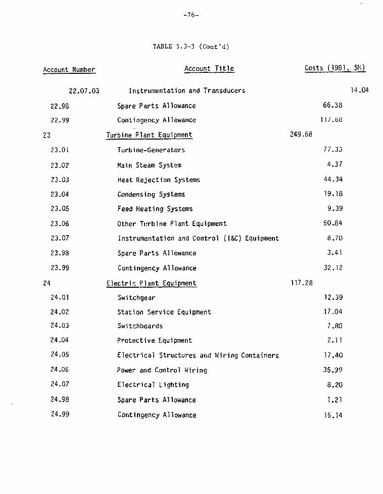
- 7 6 -
TABLE 5.3-3 (Cont'd)
Account Number
22.07.03
22.98
22.99
23
23.01
23.02
23.03
23.04
23.05
23.06
23.07
23.98
23.99
24
24.01
24.02
24.03
24.04
24.05
24.06
24.07
24.98
24.99
Account Title
Instrumentation and Transducers
Spare Parts Allowance
Contingency Allowance
Turbine Plant Equipment
Turbine-Generators
Main Steam System
Heat Rejection Systems
Condensing Systems
Feed Heating Systems
Other Turbine Plant Equipment
Instrumentation and Control (I&C) Equipment
Spare Parts Allowance
Contingency Allowance
Electric Plant Equipment
Switchgear
Station Service Equipment
Switchboards
Protective Equipment
Electrical Structures and Wiring Containers
Power and Control Wiring
Electrical Lighting
Spare Parts Allowance
Contingency Allowance
Costs (1981, 5K)
14.04
66.38
117.68
249.68
77.33
4.37
44.34
19.18
9.39
50.84
8.70
3.41
32.12
117.28
12.39
17.04
7.80
2.11
17.40
35.99
8.20
1.21
15.14

-77-
TABLE 5.3-3 (Cont'd)
Account Number Account Title
25 Miscellaneous Plant Equipment
25.01 Transportation and Lifting Equipment
25.02 Air and Water Service Systems
25.03 Communications Equipment
25.04 Furnishing and Fixtures
25.98 Spare Parts Allowance
25.99 Contingency Allowance
26 Special Materials
TOTAL DIRECT COST
91 Construction Facilities, Equipment andServices (10%)
92 Engineering and Construction ManagementServices (8%)
93 Other Costs -(5%)
SUBTOTAL 2123.57
1980 1986Constant Then-Current
94 Interest During Construction 276.70
95 Escalation During Construction 0.00
TOTAL CAPITAL 2400.27
$/kWe 2000
Costs
40.77
0.25
1726.48
172.65
133.12
86.32
(
15
12
6
0
0
5
1981, JM)
.68
.35
.22
.75
.52
.25

-78-
TABLE 5.3-4
HYFIRE TOKAMAK COST ANALYSIS
ACCOUNT 23 TUREINE PLANT EQUIPMENT
23.05 FEEDHEATING SYSTEM
No. of Total CostUnits Component ___i_n _3 M
2 Oxygen After Cooler Cooling Water Circulating Pump 0.310
5 Water Feed to Feed Preheater Circulating Pump 2.02
6 Boiler Superheater Circulating Pump ii.83
5 Make-up and Recycle Water Circulating Pump .821
4 Feed Preheater 68.92
4 Desuperheater Condensers for Degassing Heater 13.22
1 H20-He Vapor After Cooler for Degassing Heater .371
7 Desuperheating Condensers for Feedwater Heater 46.13
2 H20-He Vapor After Cooler for Feedwater Heater 5.27
TOTAL 139.892

-79-
TABLE 5.3-5
VALUES FOR FjD(. AND
ConstructionPeriod (Yr)
4
5
6
7
8
9
10
Constant DollarEconomic Analysis
Mode
(AssumedCapital =
(Escalation [
FIDC
.081
.108
.129
.152
.170
.192
.221
Cost of5%/year)*ate = None)
FEDC
-0-
-0-
-0--0-
-0-
-0-
-0-
Current DollarEconomic Analysis
Mode
(Assumed Cost ofCapital = 10%/Year)
(Escalation Rate = 5%/Year)
IDC EDC
.191
.251
.316
.388
.466
.551
.644
.122
.155
.190
.225
.261
.229
.338

-80-
in constant 1981 dollars and $8138.38 M ($3198 M-STARFIRE) in the then current
1987 dollars. These estimates result in the cost of hydrogen for HYFIRE to be
c10.74/MBtu in 1981 constant dollars utilizing a plant availability factor of
80%.
Since the plant will be the tenth-of-a-kind with the majority of the
design and construction problems resolved, an abbreviated Table 5.3-2 is also
developed which is limited to Accounts 20, 21, 22, 23, 24, 25, and 26 and with
the spare parts and contingency allowances eliminated.
In Table 5.3-2, it is seen that the total direct cost is $3873 M with
the cost of hydrogen coming to $7.14/MBtu. This cost compares competitively
with the price of hydrogen generated from natural gas and coal which ranges from
$4.00 to $7.00/MBtu.
C. Cost Drivers
1. The total cost is naturally determined from the sum of the vari-
ous input items. Some of these individual high-cost drivers (Table 5.3-1) are
found tv. be located as follows: Account No. 21, Structures and Site Facilities,
($501.17 M for HYFIRE and $346.58 M for STARFIRE), Account No. 22, Reactor Plant
Equipment, ($2218.59 M for HYFIRE and $968.62 M for STARFIRE), and Account No.
23, Turbine Plant Equipment ($1505.42 M for HYFIRE and $249.68 M for STARFIRE).
2. The HYFIRE system has four buildings which require heavily
shielded construction similar to the reactor building.
HYFIRE Tokamak Cost Estimate STARFIRE Cost Estimate
Reactor Building $ 57.92 M $157.44 M
Hot Cell Building $ 71.40 M $ 53.69 M
Electrolyzer Building $103.66 M $
Process Module Building $ 31.17 M $
TOTAL $264.15 M $211.13 M

-81-
This additional $53.02 M is brought about by the fact that the
reactor is larger and the electrolyzer and recuperators (which were not part of
STARFIRE) must be located as close to the reactor as possible to minimize the
large exnense due to the high temperature piping connecting the reactor blankets
to the electrolyzers and to the recuperators (see Fig. 4.3-1).
3. The higher cost components in the Reactor Plant Equipment group-
ing are:
ESTIMATED COST
Component
Blanket and First Wall
Shield
Magnets
rf Heating and Current Drive
Primary Support Structure
Power Supply
Helium Heat Exchangers
Primary Helium Circulation Pumps
Secondary Helium Circulating Pumps
Oxygen After-cooler
Recuperators at H20-He
Oxygen Recuperator
Boiler Superheater
Boiler Superheater Feed Pumps
First Wall Pressurized H2OCirculating Pumps
TOTAL
HYFIRE
-co
•CO
<o-c
o•C
O
$
CO
-
$
$
$
$
co-co-
$
$
I Tokamak (M)
210.02
474.48
257.36
50.24
79.11
79.35
217.04
76.71
30.82
2.85
228.47
7.98
279.79
1.50
6.36
$2002.08
STARFIRF (M)
$ 82.36
$186.07
$121.57
$ 33.49
$ 32.74
$ 52.90
$
$
$
$ —
S
s ———
$ —
$ —
$ —
$509.13

-82-
The additional cost of $1493 M for HYFIRE over STARFIRE is
brought about by two main factors. The first is the result of scaling up the
cost of the first five items to provide for the higher thermal power (6000
MW(th) rather than 3500 MW(th)), and the assumed requirements of using much more
expensive material and fabrication for the blanket than was used for STARFIRE
due to the higher temperatures and more complicated H^<3ign. The second major
cost driver is the additional nine items of equipment (He heat exchangers, etc.)
which have been estimated to cost approximately $852 M. Again, it should be
noted that no firm design exist for these equipment components so that the cost
is an estimate which would be changed once additional analysis and design have
been completed.
4. The higher cost components in the Turbine Plant Equipment
grouping are:
Component
Turbine Generators
Main Steam System
Heat Rejection Systems
Condensing Systems
Feed Heating Systems
Other Turbine Plant Equipment
Instrumentation and Control
ESTIMATED COST
HYFIRE Tokamak (M) STARFIRE (M)
$
$
$
$
$
$
s
154.10
78.35
105.50
139.89
242.53
35.04
$
$
$
$
$
$
$
77.33
4.37
44.34
19.18
9.89
50.84
9.70

-83-
ESTIMATED COST (Continued)
Hydrogen Condition System
H2-H2O Vapor Comp. (Stages 1-8) $ 23,25 $ —
Post Comp. After-cooler (Stages 1-8) $ 39.87 S
Piping, Valves, Supports $ 21.35 $
H2-H2O Vapor Comp. (Stages 9-11) $ 22.51 $
Post Comp. After-coolers (Stages 9-11) $ 46.05 $
Scrubbing Tower, Canned Pumps and Pall
Rings for Raw Hydrogen $ 6.71 $
Evaporator for Deactivating Scrub Water $ 3.10 $
Final Hydrogen Product Drying Towers
and Molecular Sieve Auxiliaries $ 19.97 $
Electrolyzer $ 406.09 ?
TOTAL $1344.31 $214.15
The additional cost of $1130 M for HYFIRE over and above that of
STARFIRE is due to various factors. All of the hydrogen conditioning sy-tevn
cost (3589 M) is unique to HYFIRE. The difference in the turbine cost is par-
tially due to the fact that HYFIRE has three turbines while STARFIRE has only
one. Other contributors to the difference are the following:
a) The presence of substantial amounts of hydrogen in the steam
leads to equipment complications and low overall heat trans-
fer coefficients.
b) Stemming from the design goal of keeping the dimensions and
weights of the equipment within the capacity of the cranes,
monorp.il handling devices, and maintenance -acilities; many

-84-
smaller units are specified as a rule instead of one or a
few large units.
c) In addition to losing the cost advantage rasulting from few-
er and larger equipment items, the multiplicity complicates
and substantially increases the piping and installation
cost.
d) The low-pressure turbine's feed is a steam-hydrogen mixture
with a 0.099 mole Rz/EzO ratio for HYFIRE which is in con-
trast to the usual design for fusion reactor-driven electric
power plants which normally operate only on steam.
e) The feed-water system is also much more complicated than in
a normal reactor plant. Since there is a large amount of
hydrogen included in the turbine extraction stream, numerous
additional components are required for the system.
D. Contingency and Spare Parts Allowances
1. Contingency
As noted in Ref. 2, the contingency allowance is an amount added
to an estimate and the total amount that is reasonably expected to be spent,
considering the degree of uncertainties in the estimated quantities, prices,
labor productivity, etc. embodied in the detailed estimates. The contingei cy
alJowance is added to an estimate to reduce the risk of overrun to an acceptable
level. For the conceptual level of design for fusion plant Accounts 21, 22, 23,
24, and 25, a contingency allowance of 15% of estimated cost is recommended.
Since HYFIRE is assumed to be the tenth-of-a-kind plant, it is feasible to lower
this contingency allowance. HYFIRE and STARFIRE use 10% for Accounts 21, 22,
23, 24, and 25.

-85-
2. Spare Parts
Reference 25 indicates that the type and number of spare parts to
be provided in inventory at the start-up of a power plant is decided by the own-
er of the plant. Common practice indicates that a reasonable cost allowance for
the value of spares in inventory falls in a fairly consistent range of percent-
ages of major equipment costs. This allowance may also be expressed as a func-
tion of total cost of installed equipment, since the relationship between major
equipment cost and total cost of equipment and materials remain relatively
constant.
HYFIRE has used Refs. 1 and 2 recommended spare parts as indicat-
ed below:
Account Number Spare Parts Allowance
21, 22, 23 • 2%
24 4%
25 3%
These percentages do not account for any permanently installed
spare components which can be employed by the opening and closing of electrical
switches and valves. The cost of permanently installed spare units is included
in the cost of components.
E. Indirect Cost
Reference 3 discusses the philosophy of indirect costs for Accounts 91
(Construction Facilities, Equipment, and Services), 92 (Engineering and Con-
struction Management Services), and 93 (Owners). HYFIRE has utilized the per-
centages which were rationalized for the STARFIRE Report as noted.
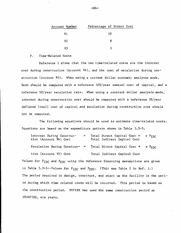
-86-
Account Number Percentage of Direct Cost
91 10
92 8
93 5
F. Time-Related Costs
Reference 1 shows that the two time-related costs are the interest
cost during construction (Account 94), and the cost of escalation during con-
struction (Account 95). When using a current dollar economic analysis mode,
both should be computed with a reference 10%/year nominal cost of capital, and a
reference 5%/year escalation rate. When using a constant dollar analysis mode,
interest during construction cost should be computed with a reference 5%/year
deflated (real) cost of capital and escalation during construction cost should
not be computed.
The following equations should be used to estimate time-relatad costs.
Equations are based on the expenditure pattern shown in Table 5.3-5.
Interest During Construe- = Total Direct Capital Cost + x FJQCtion (Account 94) Cost Total Indirect Capital Cost
Escalation During Construe- = Total Direct Capital Cost + x FgDC
tion (Account 95) Cost Total Indirect Capital Cost
Values for F^DC and F-^QQ using the reference financing assumptions are given
in Table 5.3-5—Values for FIDC and FEDC. (Thic was Table 2 in Ref. 1.)
The period required to design, construct, and start up the facility is the peri-
od during which time related costs will be incurred. This period is known as
the construction period. HYFIRE has used the same construction period as
STARFIRE, six years.

-87-
G. Cost of Hydrogen
Reference 1 describes the means to determine the total busbar energy
cost of the total electricity cost. It indicates that the total cost of energy
from a fusion reactor electricity producing facility is to be computed as a
function of the following components:
1. Plant availability factor;
2. Financial assumptions;
3. Fixed charge rate;
4. Capital cost;
5. Annual operating and maintenance cost;
6. Annual scheduled component replacement cost;
7. Annual fuel cost; and
8. Plant capacity .
These same components are required to determine the cost of hydrogen
which the plant produces. Therefore, the formulas developed in Ref. 1 for total
busbar energy cost can be used to estimate the total cost of hydrogen by chang-
ing the PC (Plant Capacity) from kWh/yr to #H2/yr.
The Ref. 1 formulas for Total Busbar Energy Cost for both the current
dollar economic analysis mode and the constant dollar economic analysis mode are
given below.
1. Constant Dollar Economic Analysis Mode
The constant dollar economic analysis mode assumed general infla-
tion rates and escalation rates are equal to zero. The equation that should be
used to determine total energy cost is as follows:

-88-
Cc(fcr)Total Busbar Energy Cost (mills/kWh) =
(Pc) (PAF) (10 J)
where:
Cc = facility capital cost (dollars),
fcr = annual fixed charge rate (= .10),
co&m = annual operating and maintenance cost (dollars),
Cp = Annual fuel cost (dollars),
C s c r = annual scheduled component replacement cost (dollars),
PC = plant capacity (kWh/yr), and
PAF = plant availability factor (= %/100).
The plant capacity for the HYFIRE Tokamak. is 145000 #H2/hr or 1270 x
105#H2/yr.
2. Current Dollar Economic Analysis Mode
The current dollar economic analysis mode assumes that general
inflation and escalation will occur. Costs are escalated to reflect this
assumption. The total busbar energy cost figure is a nominal or actual first
year busbar energy cost. For this reason, annual operating and maintenance
costs, annual scheduled component replacement costs, and annual fuel costs that
were estimated using preconstruction year price levels are escalated to first
year of facility operation price levels. The equation that should be used to
determine total busbar energy cost is as follows:
C (fcs) + C (E+1)P + C (E+1)P + C (E+1)P
Total Busbar Energy Cost = — — — — ^(mills/kWh) (PC) (PAF) (10 )

-89-
where
Cc = facility capital cost (dollars),
fcr = annual fixed charge rate (= .15),
C0&m = annual operating and maintenance cost (dollars),
E = annual escalation rate (= .05),
P = construction period (years),
Cscr = annual scheduled component replacement cost (dollars),
Cf = annual fuel cost (dollars),
PC = plant capacity (kWh/yr), and
PAF = plant availability factor (= %/100).
HYFIRE used the STARFIRE Report (Ref. 6) estimates (escalated) as
the basis for the following':
a) annual operating and maintenance,
b) annual fuel cost, and
c) annual scheduled component replacement cost. (HYFIRE
Component Cost Used).
The plant availability factor was taken as 80%.

- 9 0 -
ACKNOWLEDGEMENTS
The e d i t o r acknowledges the c o n t r i b u t i o n made by those l i s t e d a t the be -ginning of the Repor t . He a l s o wishes to exp re s s h i s deep a p p r e c i a t i o n to Mrs,Eleanor Dahl and Ms. Jeanne Danko for p r e p a r a t i o n and typing of the manuscr ip t .
REFERENCES
Chapter 1
1. J .A. F i l l o , e d . , HYFIRE: Fus ion/High-Tempera ture E l e c t r o l y s i s ConceptualDesign Study, BNL Report i n P r e p a r a t i o n .
Chapter 2
1. J .A. F i l l o , e d . , HYFIRE: Fus ion/High-Tempera ture E l e c t r o l y s i s ConceptualDesign Study, BNL Report in P r e p a r a t i o n .
Chapter 4
1. C.C. Baker e t a l . , STARFIRE - A Commercial Tokamak Fusion Power PlantStudy, ANL/FPP-80-1, 1980.
2 . J .A. F i l l o , e d . , HYFIRE: Fus ion/High-Tempera ture E l e c t r o l y s i s ConceptualDesign Study, BNL Report i n P r e p a r a t i o n .
Chapter 5
1. C.C. Baker e t a l . , STARFIRE - A Commercial Tokamak Fusion Power PlantStudy, ANL/FPP-80-1, 1980.
2 . S.C. Schu l t e et a l . , "Fusion Reactor Design S tud ies - S tandard Accounts f o rCost E s t i m a t e s , " PNL-2648, May 1978.
3 . S.C. Schu l t e et a l . , "Fusion Reactor Design Studies - S tandard Accounts forCost E s t i m a t e s , " PNL-2987, September 1979.
4 . M. P e t e r s and K. Timmerhaus, P lan t Design and Economics fo r ChemicalEng inee r s , McGraw H i l l , New York, 1975.

A-l
APPENDIX A
PERFORMANCE OF THE HIGH-TEMPERATURE ELECTROLYZER TUBES
The performance of the high-temperature electrolyzer using current and fu-
ture technology can be estimated from fuel cell tube design data developed for
high-temperature solid oxide fuel cells. The present-day technology consists of
materials and construction extended to active tube lengths of 1.56 meters.
Operating conditions for the electrolyzer tubes are defined by inlet steam tem-
perature, by flow rate, and by the current density, coupled with electrolyzer-
tube geometry and materials of construction. Conversely, the steam temperature
and molal rstio of inlet-steam-to-product hydrogen and the current density will
define the operating conditions. An examination of operating performance and
its electrolyzer efficiency follows.
Tube Geometry and Materials
The present fuel cell tube geometry consists of concentric electrolyzer
elements that are one centimeter in length. Each element is connected in
series to its two contiguous elements, such that the element-to-element spacing
is i 1/4 centimeters. For convenience, this analysis deals with an electrolyzer
element geometry that places the oxygen electrode on the inside of the tube and
the hydrogen electrode on the outside of the tube, i.e., the steam (and hydro-
gen) flow occurs on the shell-side of the electrolyzer and the oxygen flows
within the electrolyzer tubes. The geometry is best described by the two sche-
matics shown in Figs. 2.1-1 and 2.1-2 (Section 2 of this report) with the above
proviso that the detail shown in Fig. A-l has the 02 electrode and H2 electrode
exchanged. Tube and cell geometry characteristics are listed below:

A-2
Tube Geometry
Support tube, i.d.
Support tube, o.d.
Oxygen electrode, o.d.
Electrode, o.d.
Hydrogen electrode, o.d.
Length
Cell Geometry
1.
1.
1.
1.
1.
156
070
270
410
418
438
cm
cm
cm
cm
cm
1
0
125
4
.000
.250
.442
cm
cm
2cm
Length per cell
Interconnect space
Cells per tube
Mean tlectrolyte area
The tube material is described by its electrical resistivity.
All polarization effects are disregarded; the diffusion polarizations are
not very large compared with the resistivity effect and slow polarization at
tube temperatures of 1100°C and above can be neglected. The tube material is
presently constrained to tube temperatures below, and at 1100°C, but future de-
velopments will likely permit operation at temperatures up to 1200°C (1473 K).
The resistivity of the four tube components are given below:
P(electrolyte) = 2.95 x 10~3 Exp (10,350/T),
P(Oz electrode) = 8.11 x 10"3 Exp (600/T), "cm
P(H2 electrode) = 2.98 x 10~3 Exp (-1392/T), ^
P(interconnect) = 1.26 x 10~3 Exp (4690/T), ^c

IT
11
11
X
X
X
1
1
1
.414
( 1 ..340
( 1 ..428
cm x
25/2)cm x
25/2)cm x
.004
1.
cm0.
cm0.
cm
000
07
Oi
cm
cm
cm
A-3
Resistance of each component is computed as follows:
R(electrolyte) = Pg -°°4 ^
R(0o electrode) = PI a
R(HO electrode) = PI c
R(interconnect) = P. -,—.-— . --.
l if x 1.414 cm x 0.250 cm
Resistance values for further computation were selected at 1273 K and
1423 K. (See Table A-l.)
1273 K 2R ± = 6.85-02 "
1423 K 2R ± = 5.82-02 "
Thermodynamic Functions
The electrolysis of water is described by the enthalpy and Gibbs-free
energy change for the reaction:
H2(g) + 1/2 02(g) = H2O(g)
The standard Gibbs-free energy and standard enthalpy are given by
AG° = -57,410 + 0.94 T In T + 1.65 x 10"3 T2
-3 .7 x 10~7 T3 + 3.92 T, (cal/gmol, K)
AH° = 57,410 - 0.94 T - 1.65 x 10"3 T2
+ 7.4 x 10~7 T3 , (cal /gmol, K)
The Gibbs free energy i s given by
AG = AG° + RT In Kp + RT In p ,

A-4
TABLE A - l
COMPONENT RESISTANCE OF CELL,
Component 1273 K 1373 K 1473 K 1573 K
Electrolyte 9.015-03 4.987-03 2.989-03 1.912-03
Anode (02) 2.757-02 2.664-02 2.586-02 2.520-02
Cathode 1.391-02 1.506-02 1.614-02 1.714-02
Interconnect 1.801-02 1.377-02 1.092-02 8.920-03
z 6.850-02 6.046-02 5.591-02 5.317-02

A-5
where:
K -
(R, cal/gmol K; T, K; Pt, atm; n. t=c1 fraction ">.
For tube operation, Pc = 34 atm and 11% of the steam will electrolyze to
H2 and 1/2 02. The mol fraction values are:
0.00 < n a < 0.11
0.89 < n < 1.00 , (these are on the shell-side), andH 2 ~
n = 1.00 , (this is inside the tube)
The Nernst voltage for 0.00 < ix, < 0.11 was computed from:- H 2 -
x 4.184 ^ t s e c m o l ( E_ v o l t s A G c a l / g m o l )cal Coulomb °E = _ £ § _ . x 4.184 ^
2 x 96500 cal Coulomb
Values for pertinent data at 1273 K follow, with the note that in the
1273 K calculation, polarization effects, not accounted for in this calculation,2
will reduce cell (and tube) performance with increased i R losses and higher
N°rnst voltages than those indicated here. The 1273 K case, as calculated in
Table A-2, is included to indicate upper-bound performance of a low-temperature
tube.

A-6
TABLE A-2
GIBBS FREE E.JERGY AND NERNST VOLTAGES
Temp. AG°,-l /2 RT In p t E ( v o l t s ) , a t nn? (mol)
(K) (cal /g-mol H2O)
.003 .007 .010 .030 .050 .070 .090 0.11
1273 -41954 -4467 .6875 .7342 .7540 .8155 .8427 .8643 .87r'3 .8915
1423 -39884 -4993 .6115 .6679 .6900 .7587 .7913 .8132 .8300 .8437

A-7
The average cell voltage along the tube length is approximated by:
0.11J Edn
E = 0.11/ dn
0.00
from which
£ = .85 vo l t s , at 1273 K,
E = .80 v o l t s , at 1423 K.
The values of AH and AH/AG are computed below
AH = -59,754 cal/g-mol (of steam, at 1273 K)
AH = -59,956 cal/g-mol (of steam, at 1423 K)
AG = -39,054 cal/g-mol (of steam, at 1273 K)
AG = -36,870 cal/g-mol (of steam, at 1423 K)
AH/AG = 1.530, (at 1273 K)
AH./'AG = 1.626, (at 1'23 K)
Tube Performance
The thermal and e l e c t r i c a l performance of the tube can be calcula ted from
the data of tne e a r l i e r sec t ions . An 11% decomposition of steam requires a
change in enthalpy of:
Ah = -6,573 cal/gmol (of steam, at 1273°K)
Ah = -6,595 cal/gmol (of steam, at 1423°K)

A-8
The tube performance wi l l vary with current densi ty , as indicated in Table
2A-3, with the ca lcu la t ion of i R given by:
i2Rn = ( j 2 ) (4.44 cm2)2 R x n
where
j = current dens i ty , amps/cm ,
R = ce l l r e s i s t ance cm £R^ of Table A-l) , and
n = 125 c e l l s / t u b e .
The e l e c t r o l y s i s energy is given by:
* - 2Ag = E j .44 cm / c e l l x 125 ce l l s / t ube
Ag, ( r a t e of Gibbs-free energy change)
Ah =-§ AgAG
Ah, (rate of enthalpy change)
2 * *
With i Rn loss less than Ah - Ag) heat must be added to the tube electroly-
sis reaction by convection from the steam.q = An = Ag - i
2Rn
The case ma-/ exist , but not here, where q must be removed from the electrolysis2
tube; this occurs if the i R loss exceeds Ah - Ag.
The calculations at two temperature levels follows:
The steam flow rate (m) is calculated by
m = Cjjl'). (all data at 1273 K for Table A-3 and at 1423 K for Table A-4).
The temperature fall of the steam-hydrogen mixture is calculated by:
^ 2 - , $ = 9.032 cal/g-mol K, 1273 K, and 9.179 cal/g-mol K; 1423 K.m $

A-9
Parameter
Ah (cal/sec)
Ag (cal/sec)
2i R (cal/sec)
q (cal/sec)
m (g-mol H20/sec)
ST (K)
TABLE A-3
TUBE PERFORMANCE AT 1273 K
2j=0.5 a/cm
o5.9
56.2
10.1
0,4
68.8
44.9
6.5
19.7
1.3-02
136.0
17.4
1.0-02
155.0
0.3
51.5
33.7
3.6
14.2
0.78-02
173.0
0.2
34.4
22.5
1.6
10.3
0.52-02
191.0
1.2 1.1 1.1 1.1
* Also, this equals the ratio of averge cell voltage to average Nernst voltage,e.g., at j=0 amps/cm , the average cell voltage will be 1.18 x .85 = 1.0 volts

A-10
Parameter
•Ah (cal/sec)
•Ag (cal/sec)
i2R (cal/sec)
•q (cal/sec)
•m (g-mol H20/sec)
5T (K)
Ag + i2R*
Ag
TABLE A-4
TUBE PERFORMANCE AT 1423
j=0.5 a/cm2
86.217
53.038
8.575
24.604
1.3072-02
177.0
1.16
0.4
68.974
42.430
5.488
21.056
1.0458-02
192.0
1.13
K
0.3
51.693
31.800
3.087
16.806
0.7838-02
207.0
1.10
0.2
34.395
21.220
1.372
11.903
0.5209-02
223.0
1.06

A-ll
The production of hydrogen from the tubes is fixed by the current density
for both cases, 1273 K and 1423 K, as follows:
2 lg-mol H2
m(g-mol H2/sec) = j x 4.442 cm /cel l x 125 cells x 2 x % ) 5 0 0 ^
The values of Table A-3 and Table A-4, calculated from m^ = 0.11
check those from the coulomb transfer rate of Row 1.
The ratio of e lectr ic to thermal energy 4g + i R: q for both cases follows:
j = 0.
3 .
2 .
5 a/cm
37
50
2
2
.4
.96
.28
2
2
•2.62
.08
•
2.
1.
2
34
99
Table A-3 (1273 K)
Table A-4 (1423 K)
Discussion
A HTE electrolyzer has been evaluated for performance parameters at two
temperature levels, 1273 K and 1423 K. The thermal performance is not changed
much at the two temperature levels. With a situation of slight temperature
dependence, the need to perform a segment-by-segment" calculation to account for
temperature dependence is unnecessary. However, polarization effects, both slow
and diffusive, have been neglected in the calculation.
The diffusive polarization can be neglected, especially if the porosity of
the support tube is high, e.g., at 30% and any effect i t may have would be
greatest at 0.5 amp/cm .
Slow polarization is strongly temperature dependent, changing by a factor
of ten times or so, between 900° and 1100°C, with present construction and elec-
trode materials. I t can be considered negligible at 1100°C; with near-term ma-
terials and construction, i t is expected to control this to lower values at
900°C.

A-12
The calculated performance parameters indicate an acceptable electrolyzer
performance. With near-term materials and construction techniques negating the
above discussed polarization effects, one can expect this performance level to
be obtainable in future HTE el-ctrolyzer tubes.

B-l
APPENDIX B
A COMPUTER PROGRAM FOR ESTIMATING THE PERFORMANCE OF A
HIGH-TEMPERATURE SOLID OXIDE ELECTROLYZER
R. E. Grimble
Introduction
A high-temperature solid oxide electrolyzer design for generating hydrogen
from steam is described in Section 2. Performance calculations are described in
Appendix A for several operating conditions. A computer program (LIZA) has been
written to facilitate future performance calculations and to permit more exten-
sive parametric studies.
Calculation Procedure
The analytical relationships and the method of calculation is similar in
the computer program to that described in App. A, except that in the program:
1. Conditions are calculated explicitly for the axial section and numeri-
cally summed;
2. allowance is made for a difference in hydrogen partial pressure on the
hydrogen electrode relative to the bulk stream as determined by a
laminar flow mass transfer coefficient; and
3. allowance is made for oxygen partial pressure difference through the
porous support tube due to viscous flow resistance.
The geometry is the same as shown in Fig. 2.1-2 but with arbitrary values
of the individual physical dimensions. The input consists of:
1. The values of the physical dimensions,
2. the steam inlet temperature, pressure, and flow rate, and
3. the fraction of steam electrolyzed. This is discussed below in more
detail.

B-2
The output includes:
1. Current required;
2. voltage required; and
3. temperature changes in the steam stream.
A program listing is included at the end of this section.
Data Input
In the notation used here, each axial segment is a cell. Input cards are
prepared as follows.
Card 1 - Any alpha-numeric string in the first sixty columns to name or identify
the case being considered.
Card 2 - Diameter measurements of cell components (in centimeters). These con-
sist of six numerical values each in a ten-column interval according to an F
10.6 format:
A. Columns 1-10: support tube inner diameter, cm;
B. Columns 11-20: support tube outer diameter, cm;
C. Columns 21-30: oxygen electrode outer diameter, cm;
D. Columns 31-40: electrolyte outer diameter, cm;
E. Columns 41-50: hydrogen electrode outer diameter, cm; and
F. Columns 51-60: equivalent fuel passage diameter for estimating
mass transfer coefficient, cm.
Card 3 - Two integers right justified in columns 1-10 and in columns 11-20;
respectively. The first is the number of axial sections and the second indi-
cates the frequency of printout (for example, the number 3 in column 20 results
in numerical data printed out for every third axial section).

B-3
Card 4 - Length measurements of the cell and i t s components (in centimeters).
These consist of five numerical values each in a ten-column interval according
to an F 10.4 format.
A. Columns 1-1C: the overall cell (axial segment) length, cm;
B. Columns 11-20: oxygen electrode length, cm; and
C. Columns 21-30: electrolyte length, cm.
(The overall assembly length is calculated from number of cells and cell
length.)
Card 5, 6, 7, 8, and 9 - Each of these cards contains two numbers in scientific
notation, using an E 10.4 format, which correlate component e lectr ic ial res is-
tivity (in ohm-cm) with temperature. A let ter "A" in Columns 1—10 and a let ter
"B" in Columns 11-20 permit resist ivi ty to be calculated from the formula
P = Ae ( B / T )
where T is absolute temperature in degrees Kelvin. These cards represent
respectively:
1. the oxygen electrode;
2. the electrolyte;
3. the interconnect;
4. the hydrogen electrode; and
2
5. the electrode surface polarization resistivity (in ohm-cm ).
Card 10 - In Columns 1-10, the support tube permeability in Darcys' and in Col-
umns 11-20, the center-to-center tube spacing in a tube array in centimeters.
These are entered according to a F 10.4 format.

B-4
Card 11 - In Columns 1-10, the steam absolute pressure in atmospheres; in Col-
umns 11-20, the steam inlet temperature in degrees centigrade; in Columns 21-30,
the steam flow rate per tube in g—moles/sec; and in Columns 31-40, the fraction
of steam to be electrolyzed. These entries follow an F10.4 format.
Any number of eleven card data sets may be stacked together.
Output
A sample input deck and printout is shown at the end of this Section and is
self-explanatory. First the input data are printed out. The current require-
ment (per tube) is printed out. Conditions at specified segments along the tube
are printed out including the net voltage requirement and the overall tempera-
ture changes.

QQrQ
GO OOw O O
Q O j a O OODOODCDCCCOOOOOCWCOOOOOOCCIXIOCCooaoao©aooaooocKDooaoo^°ooociooooOOOOOOOCDOODGOOOOOOOOODOCOOOOOC
-oj-cooqjQ'O'QooooaooQooooooooeSO00S00COOCC090X0X09OCO0CD00C00900003=103033000000000009003030000O00D3900C0000000QO0OOO900CO
*- — (DO O
0-000000000^-000000000030000003• OOOOODOOOOOOOODOOOODOOOOOOOOOCiC
z. oooooooooooaoooooooooooooooooooO 0900000090000930033000SOOOO 3 O OCD
'H'i I LI1 ' <•» I O L J i l I
« 0 a
* gOOOOQOQOOOOOOOCOOiCQClOOQOOOOOO
*- -ooooooooo^-oocoooooooooooooosooaosooooosoooocoooooosoosooooc
» 0000300000000003000000000000300o o a s s o D O O o s o a o o D o
"»•*' * « •*• ooooo—•—»-«• e DD^oooooooc ooosooooooooooooaooo— • " c — oo-Toooaoooooo o aooooooooooQoooaoocooooooooooooo
^ •- » opooooooooooo •• Docso&oo^aoooooLcoaJcosDCioocasos

B-6
(M00000DCOC0C00O000CXDO500000Q000000O0aDfoooaaooaoooocoooooooocooooocMOOOOOoooooooaoaoooaoooOO OOOOOOOOOOOCttOOO OCO COOOOODaOODOOCOOoOOCOOOCOOGOOOaaooaaoacooaoooocnoooaoooooixioooooociooooaaoooooaoaooGooaooaoDoooaooooooocoooocooooooooQDooacoocxsoooooo
OOO O— ~ - — —ooo ooooe oooo ooooo oooo oooao o
OW >tw
•"ft. • * '
uJ* X O
F-« a.i i mw«
ooooooaoooooaooooaoooaooaaooooooooooooooooooooooooiOOOOOOOOOOOOOOOOOOOOOOODOOOODCmDOOOOOOOOOOODOOOOOOi

B-7
000030000 oOQoooooooooaoaooooooooooo aooocooooojjomooaooooaaoaoooaoooaoooaoooooOQ ooaooooOOoooooooooooooooaoooaooooaocx3cs30COOQ OCXXIQOO
oooco oo cscoooaocooooococooo
OCX) oo ooooaoooooooouooouoo
o -a
O OOt h y • »-O • •
X -• O
O csx-» M a.'-
> 4 « l • I
" " ~ ~ ^OOOQOOOUOO*
CXJOgoOOQOOOOOQOQQOOOqOQQQOOOOOOOOQOOQOOOOOOOOOOQOOOOOOOOQOOJOQQOJOQOOOQQDoOOOOOOOOOOOOOOQoooOOOOGQOODOOOOOaOOOOC»OOOOOODOOOOOOODOOOQDOOOOOOaOOOOOOOOCDOO

B-8
30000000000000000000 O
000000000
000000
000
oocaoaoooocoaa0000000 00 cooao000000000aooooc ooa 000 00 000a oOCX3OOOO' >TU" X^OO
O
*~ o 0.0. i
BU O O
o30
00
z0E
O
z
D
O
o
o o• <
Z A
o •*«. *»
« aN- Oz otaJ
C
3CATION
ATIVE LCK
IH
oED
O O O
~taf
OOO
OOOOOO
OOOO!
0000?
—ooOOO
ooo
OOO"
oao
OOOOOOOOO
o
«o o o- o •- o
^ n »• r O •
ru *i ^ tn •*> o
•J*iO<X"M»*"0*30t> O«10«0>00COO »
p-*.aMi«»oirt«- o
»*.Mn«)t,i>rtOa- O
u w " • A* •*•*•*» «o"» O1** • * O O
—•O. u « P. O O O O» • — • • - » - * - n iOO
irtrw> •—* " ^ — • • « - * -
d. »>^O(vn«VF^N^r^oOO• i • nil ipi ipi iQi JJ 3 Qtt_— •**» "^l »*O -* » HO^IhZ(/v«— « ^ - - ^ - • • - • • •iu *lKf ril C 0*000
^v- *^> rt *-O *<? — O O
>^i-n«0"O-^ Oui v ««^ *-w *»•* *«^ • •
O Z
OW «1 OOOO*rt *-i O O O O3 < OOOO
OOOOOOOOOOOO
oooooooaooooc30oooooooaoooooooacoocx3ODOOOOOOOODOoOOOOOOOODOOOOOOOOOOOODCa
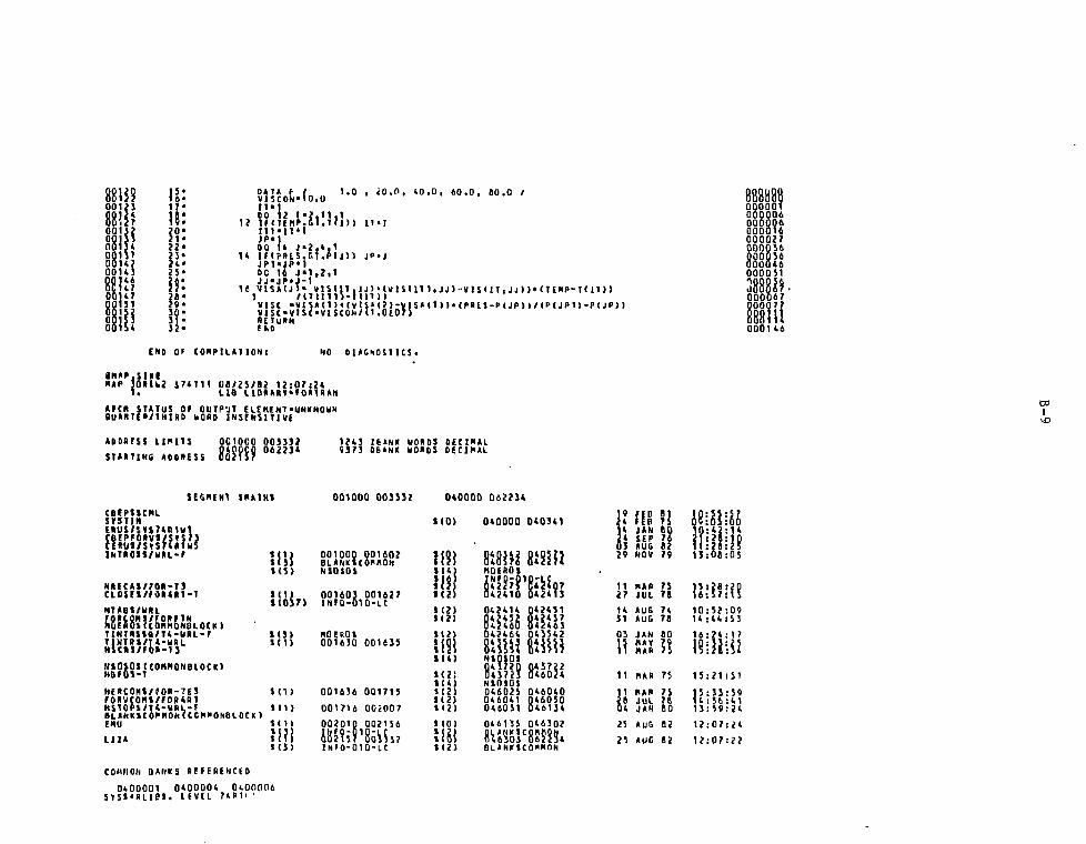
001230012400127
Q01S4001]?
oon;0014)
Hi147
6015 3B1S4
n O A T * P /VlSCOK-10.0IT'
1.0 , < 0 . 0 , 4 0 . 0 , 6 0 . 0 , SO.O /
DO 12 1*2,11,112 iM7enP.Gl.Tli)) i n i
DO U J«2.»,1u ii(pitts.r.i.ptj)) J P « J
DC 16 J « 1 , 2 , 1J J ' J P » J - 1
U V 1 S M J . 1 * V l i f I T . J J j ' t U l S d l 1 , J J ) V ! L < 1 T , J J ) ) " ( T £ H P - T < 1 1 ) 1
V I S C - « l S A ( 1 ) t ( V l S ' ( J ) - V I S » l i n « ( f » t 5 - P ( J P ) ) / ( P ( J P 1 l - P ( J P ) )
32* FKD 000U6
£N0 OF C0MPILH1 I0N; NO 01ACH0S1ICS.
RAP } 0 » U 2 S/4T11 O0/2S/82 12:07:241 . H B l lB»*Rt«tO«l«»H
AICR STATUS Of OUTP'JT £ LEH[ NTBU*R TC •/11ll NO bORD INSENSnive
at
ABORESS LIMITS 0C10G0 003])?mm 06"iA0C10G0mm 124] IBANK WORSS DEC1NAL«373 OB»HK WORDS DECIMAL
SEGMENT IMAtHI 001000 003332CBfPfSCHLBtP»»CrstinRUi/SfS741BFPP&RV1/S«SCERUt/S«S?(RiMIMTROlt/WRL-r
N»EC«1/7ORT3CL0SEWF0MM-T
NTKB1/WRLrpRcgi/roRfTN
COnMONOLQ E B C n O O L O C KTINTRSta/T4-URL-rT|NTB»/r*-URLNSCRJ/fO«-13
HSOtQJ(COftMOHBlOCK)HBfOt-T
NERCONt/fOR-TESFORVCOMS/rORtRiHSTOPi/H-UBL-fSLtHltttOI'IIOtltCCIINONBLOCK)EMUL I I A
040000 062214
1(0) 040000 0(0341
i mt (5 )
iioir)1(31i(i>
1(1)
«ii>
iiii1(3)
001000 001607BLANKiCOfflONNSOSOS
00110} 001627INfO-010-lC
NQEROt001630 001639
001636 001713
001716 002007
002010 002156
iol2iw'8o3^3?INF 0-010-U
if?}1(4)
im1(2)
1(7)1(2)
iJ(4)
S 1 2)1(2)
1 (0)mt(2)
BiBKiMQEROtkm*042410
047414Q47432042460042464
NtOlOlQ4S72Q043723NtOSOl04602S046041046Q31
046133DLANKIC8(6305
mm8t^fg70*2(13
0424310424370(}(63
8*60j(046040Q460S0046134
046302
8?2?54BLtNKlCOXMON
11 MAR 7527 JUL 7E
1431
03nii
AUGAUCJANMAYMAR
MAR
MARJULJAN
7478
R75
n80
23 AUG 82
23 AUC 82
14:44:53
16:74:17
15i?1:51
15:33:59
12:07:24
12:07:22
COMMON BANKS REFERENCED
0400001 0400004 0(000(16SYSJ'BLiel. LEVEL 74R1''

B-10
SAMPLE INP-T DECK
E L E C T P O L Y Z E R P •"• R FCRCAN CE
1.O7CQ 1 . 2 7 0 0 1 . 4 1 0 G 1 . 4 1 8 0 1 . 4 3 S G . 9 9 5 5
125 2
1 . 2 5 C C 1 . 2 5 0 C 1 . 0 G 0 0 . 2 5 O C 1 . 2 5 C 0
. a 1 1 4 - C 2 . 6 C C 0 + 0 3
. £ 9 i . g - C 2 . 1 C 3 5 + C 5
, 1 2 5 6 + CQ . i . t 9 C + 0A
. 2 9 o C - 0 2 - . 1 2 9 2 + 0 4
.QCCC .OCCO
2 . 0 D C 0 1 . 5 5 0 0
3 4 . C O C O 1 0 Q C . 0 G C C . 0 1 2 4 . H O C

B - l l
rwi i i i t i i i i i i i i i i i i i i i i i • i i i i i i i i i • i
• u . „- i«JQwi OBI • IT O»'~> f i o u n i irwir i nrr i v i i n n m n i nn in r
< oooooooaooaooaooooooooooooocoacoooooooo
XwV i I I I I I I I I I I I I I I I I f I I I I I t I I I I t I I I I 1 i I I I
£ 55555H i i • • •
O O O O O
> Q O * - " * r » ^ ^ ^V1-O Or<-4QiWO>0«-
CZXCS
OOOOOOOOd
IT ^w w u w u w O o tuOm »- - D Q i • -ij-l—i r rw-nn-fTf- t- «r igonrT-r i - -Y T r r»i fl nr r*fttTrr Q Q I - n jn
OOOOOo •"**-* ^ <wr ^ « - . *- - • - »
^»*oi sol
000000000000000000000000000000000000000
B-12
l l t l t l l l l l l l l l t l l l t l l l t l
I r I I I I I I I I t I I I I I I I I I • i > I
oo cooaooooooooaotiDOoooao
I I » I t I
ZXZZ<ZXZZZ»ZZZ2Z2Z2ZXXZooooooo00000000000000009

C-l
APPENDIX C
BASIS FOR THE SIZING AND COSTING OF HYFIRE COMPONENTS
The basis for the size and the cost estimates for the various components in
Cost Accounts 22 (Reactor Plant Equipment) and 23 (Turbine Plant Equipment) are
discussed in this Section. The designs of the components and their sizing are
based on the HYFIRE flow sheets shown in Section 3 and the state points (fluid
stream temperatures, pressures, flow rates, and the amount of heat trans-
ferred). The major component items in these accounts, the number of units of
each type of component, and the component design parameters are summarized to-
gether with the cost coefficients, scale factors, and the total component hard-
ware cost (one or more units) in Table 5.2-1. The bulk of the estimated bare
equipment costs are obtained from algorithms developed from various published
costs for processing and heat transport apparatus. These algorithms involve
fractional power scaling for the main cost determinators (e.g., ft heat trans-
fer surface, brake horsepower, and design pressure, where applicable). The cost
coefficients and the scale factors are given based on the following generalized
costing algorithm:
ai a? % aA as afiCost/Unit = $ C O T Q (A) (P) (B) J (W) * (M) 3 (Q)
where Co is the cost coefficient, Y o is a multiplicative factor; oq , <*2, 03,
ai+, a5, and ctfs are scale factors; A is the external heat transfer surface area
2in ft ; P is the design pressure in psia; B is the brake horsepower; W is the
flow rate in gpm; M is the mass in pounds; and Q is the turbine output in MW.
The generalized costing algorithm is applicable to all the major components in
the cost accounts as determined by the scale factors. Thus for heat exchangers,
a3, a4, 25, and a$ are zeros and the costing algorithm reduces to:

C-2
« aCost/Unit = $C T (A) (P)
o o
The specific functions of the major components and general descriptions of
the components are discussed in the following sections.
Account 22 - Reactor Plant Equipment
22.02.01 Primary to Secondary Helium Heat Exchangers
This consists of a parallel set of 420 heat exchanger modules that
transfer heat from the primary helium to the secondary helium. Each module is a
countercurrent flow, floating head design with one tube pass. The tubes and
shell are made of Inconel. Each module contains 1297 tubes 0.25 inch o.d. and
0.022 wall thickness with 0.375 inch triangular pitch array. The shell is 15.25
inch o.d. and 0.375 inch thick.
22.02.02 Primary Helium Circulating Compressors
These compressors provide the circulation of the primary helium cool-
ant that transports the beat generated in the tritium breeding blankets to the
primary helium-to-helium heat exchanger. Twenty-eight single stage centrifugal
compressors were selected. The brake horsepower per unit is 9000 HP and the
overall dimensions p f unit are 8.3 x 9.9 feet. Costing was based on a design
pressure of 720 psia and helium flow rate of 1.33 x 10 lb/hr.
22.02.03 Secondary Helium Circulating Compressors
The secondary helium circulating compressors move the secondary helium
through the helium-to-helium primary heat exchanger and transports the heat to
the boiler-superheater. Twenty-eight single stage centrifugal compressors were
again selected. The brake horsepower is 3700 HP per unit.
22.02.04 Oxygen Regenerative Coolers
Eight coolers, operating in parallel, were selected. Each unit was
designed with countercurrent flow, fixed heat, one tube pass, SS-316, and with

C-3
oxygen flowing through the tubes. There are 3955 tubes per unit. The tubes are
0.375 inch o.d., 0.049 inch wall thickness and 118 inches long.
22.02.05 Boiler Superheaters
A parallel set of twelve boiler-superheaters generate the steam for
the high-pressure turbine. The boiler-superheaters consist of countercurrent
flow, floating head, one tube pass, and high nickel heat exchangers. The cold
fluid flows through the tubes. The tubes are 1 inch o.d. with a 0.109 inch wall
thickness. There are 7610 tubes per unit. The hell is 139 inch o.d. and 0.6
inch thick and has a length of 387 inches.
22.02.06 Pressurized Water Circulating Pumps
These pumps circulate pressurized water through the first wall. The
pumps are of the single stage, centrifugal type—each one delivers 12,000 gpm.
The design pressure is 4300 psia. The brake horsepower is 510 HP per unit.
Thirteen operating units are required. Two installed spares are provided.
Account 23—Turbine Plant Equipment
23.01 Turbine Generators
The sizing and costing of the power generating turbines were scaled
from STARFIRE. A scale factor of 0.6, based on the turbine output, was as-
sumed. The three different turbines involved are the high-pressure turbine,
low-pressure turbine, and the oxygen turbine. The high-pressure turbine pro-
duces 524 MW of electricity (by assuming 36% overall turbine efficiency). The
low-pressure turbine produces 1628 MW, while the oxygen turbine produces 57 MW.
23.03 Plant Cooling Water Heat Dump System
Two heat dump systems are required—one that provides 80°F cooling
water and the other provides 90°F cooling water. Both systems provide 70 psia

C-4
cooling water in closed loops with cooling of returned heating water to hyper-
nbolic evaporative cooling towers. The 80°F system consists of three 2.17 x 10
3 4
gpm cooling towers and six 2.7 x 10 BHP pumps (3.6 x 10 gpm water circulating
capacity). The 90°F system consists of one 2.73 x 10 gpm cooling tower and two
2.4 x 10 BHP (1.37 x 10 gpm) circulating pumps. Both systems provide 43% ex-
cess cooling capacity.23.04.01 Main Condensers
The saturated H2-H2O vapor exhausting from the low-pressure turbine is
condensed in sixteen condensers using the plant cooling water. The design is
similar to the feed preheaters (23.05.05) with the exception of the tube length
(661 inch), number of tubes (19,400), the shell (122 inch i.d. and 1.5 inch wall
thickness), and the overall dimensions (10.42 feet o.d. x 61.08 feet long).
23.04.02 H2-H2O Vapor After-Cooler of the Main Condensers
One after-cooler processes the H2-H2O vapor generated by the sixteen
main condensers. The saturated H2-H2O vapor withdrawn from the main condensers
are cooled further by the plant cooling water in this heat exchanger. The heat
exchanger is similar to the feed preheaters (23.05.05) with the exception of the
tube length (114 inch), number of tubes (2425), shell size (44 inch i.d. with
0.25 inch wall thickness), and the external heat transfer surface area (3770
ft2).
23.05.01 Oxygen After-Cooler, Cooling Water Circulating Pumps
Two multistage centifugal pumps with 700 gpm capacities are required.
Each unit has design pressure of 1130 psia and brake power of 890 HP.
23.05.02 Circulating Pumps for Water Feed to Feed Preheater
Three multistage centrifugal pumps of 12,000 gpm capacity are re-
quired. The design pressure is 1130 psia and the brake horsepower is 12,650 HP.

C-5
23.05.03 Circulating Pumps for Water Feed to Boiler-Superheaters
Same specs as those given in 23.05.02 except design pressure of 1900
psia. Four units are required, and two spares are provided.
23.05.04 Circulating Pumps for Make-up and Recycle Water
Three pumps of single stage centrifugal design are designed for 12000
gpm capacity and 60 psia pressure. Two spares are provided.
23.05.05 Feed Preheaters
The cold boiler feedwater is heated by superheated steam extracted
from the high-pressure turbine. The condensate generated is mixed with other
streams to form feed for the boiler-superheaters. The feed preheaters consist
of four parallel operated, single tube pass designs with countercurrent flow
(with the cold fluid flowing through the tubes.) High nickel content tubes are
specified. Each unit has 14,870 tubes that have 0.625 inch o.d., 0.035 inch
wall thickness and 741 inch length. The total length accommodates a 213 inch
long desuperheating zone, 284 inch condensing zone and 244 inch condensate sub-
cooling zone. The shell has 108 inch i.d. and 1.5 inch wall thickness. The ex-
2ternal heat transfer surface per unit is 150,230 ft .
23.05.06 Desuperheater - Condensers for Degassing Heater
Cold boiler feedwater is heated by superheated steam extracted from
the low-pressure turbine. The condensate generated is mixed with other streams
t3 form feed for the boiler-superheaters. The heat exchanger is accomplished in
four parallel-operated second stage pressurized water preheaters. The heater
tubes are identical o those of the feed preheaters with the exception of the
length. The 14,870 486-inch long tubes have 149-inch long desuperheating zo: es

C-6
and 337-inch condensing zones. The shell is 108 inch i.d. with a 1-inch wall
thickness.
23.05.07 H2-HzO Vapor After-cooler of the Degassing Heaters
Boiler feed water is heated by the hot H2-H2O vapor generated by the
set of four degasser-heater units which, subsequent to cooling, is dispatched to
the third stage of the H2 product compressor-after-cooler complex. This is ac-
complished in a single heat exchanger with the same basic features as the
desuperheater-condensers described above. The 817 tubes are 191 inch long. The
shell is 46 inch in i.d. with a wall thickness of 0.75 inch.
23.05.08 Desuperheater Condenser for Feed-water Heater
Cold boiler feed water is heated in these heat exchangers (7 units) by
the hot superheated steam extracted from the low-pressure turbine. The conden-
sate generated is mixed with other streams to form the feed for the boiler-
superheaters. These heat exchangers are identical to the desuperheater-
condensers for the degassing heater described previously. The only differences
are the length of the tubes—_58 inch, the overall length of each unit (60.83
feet) and the external heat transfer area—133,400 ft .
23.05.090 H2-H2O Vapor After-cooler of the Feed-water Heater
Cold boiler feedwater is heated in two of these heat exchangers by the
hot H2O-H2 vapor generated by the set of seven feed-water heater units, which,
subsequent to cooling, is dispatched to the first stage of the H2 products
compressor-after-cooler complex. The heat exchangers are similar to the feed
preheaters with the exception of the tube length (465 inch), number of tubes
(10,940), shell dimenr ons (92 inch i.d., 1 inch wall thickness), overall dimen-
sions (7.83 feet o.d. x 42.75 feet long), and external heat transfer surface
(69,360 ft 2).

C-7
23.08 Hydrogen Plant
23.08.01 Vapor Compressors for the Hydrogen Conditioning System
A flow schematic for the hydrogen conditioning system is shown in
Fig. C-l. The H2-H2O vapor is compressed to eliminate the water from the hydro-
gen product. Multistage turboblowers are specified. The blowers are assumed to
have 70% overall efficiency. The turboblower design consists of eight stages
connected in series wiLh after-coolers interposed between stages. The design
specifications aad the operating parameters and costs of the various stages are
summarized in Table C-l. The costing algorithm was applied to each stage as
shown.
23.08.02 Intercooler—Condensers for Hydrogen Conditioning System
This is a set of heat exchangers that cool down the compressed H2-H2O
vapor product and condenses out a portion of the eight compressor stages. Each
unit has countercurrent flow of H2-H2O vapor down the outside of the tubes with
upflow of cooling water through the tubes. The condensate generated is recycled
back to the feed-water heater. The residual partially dehydrated H2-H2O stream
is feed for the next compression stage.
All units are identical as to tube size, number of tubes, and configu-
ration. The tubes are of the same design as those given in 23.05 with the fol-
lowing differences: 22,930 tubes per unit and shell i.d. of 132 inches. The
tube lengths shell wall thickness, and other parameters that vary from stage to
stage are sumarized in Table C-2.
23.08.03 Vapor Compressors for Hydrogen Product Conditioning-Polishing
The raw H2-H2O vapor from stage eight of the compressor-intercooler is
compressed to further eliminate the H2O from the H2 product. There are four
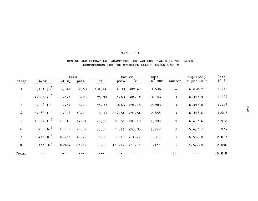
TABLE C-l
DESIGN AND OPERATING PARAMETERS FOR VARIOUS STAGiiS OF THE VAPORCOMPRESSORS FOR THE HYDROGEN CONDITIONING SYSTEM
Stage
1
2
3
4
5
6
7
8
Total
lb/hr
6.134-1O5
4.336-105
3.004-105
2.258-105
1.834-105
1.955-105
1.452-105
1.372-105
Feedmf H2
0.342
0.674
0.787
0.867
0.919
0.952
0.972
0.984
psia
2.50
3.83
6.13
10.13
17.04
29.02
49.76
85.69
0
134
95
95
95
95
95
95
95
_.
F
.44
.00
.00
.00
.00
.00
.00
.00
__
Outletpsia
4.33
6.63
10.63
17.54
29.52
58.26
86.19
149.42
°F
302.47
304.18
296.76
291.54
288.13
286.00
284.72
283.95
Unit10 BHP
3.538
3.143
2.903
2.855
2.903
2.999
3.088
3.156
Number
4
3
3
3
3
3
3
3
25
Required,ft per Unit
6.8x8.2
6.5x7.9
6.4x7.6
6.3x7.6
6.4x7.6
6.4x7.7
6.5x7.8
6.5x7.8
Cost106$
2.972
2.044
1.928
1.905
1.928
1.974
2.017
2.050
16.818
ni00
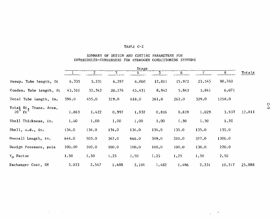
Desup. Tube Length, ft
Conden. Tube Length, ft
Total Tube Length, In.
Total Ht, Trans. Area,105 ft2
Shell Thickness, in.
Shell, o.d., in.
Overall Length, in.
Design Pressure, psia
Yo Factor
Exchanger Cost, $M
TABLE C-2
SUMMARY OF DESIGN AND COSTING PARAMETERS FORINTERCOOLER-CONSENSERS FOR HYDROGEN CONDITIONING SYSTEMS
Stagey1
6.335
43.311
596.0
1.863
1.00
134.0
644.0
100.00
1.50
3.033
2
5.531
32.342
455.0
1.422
1.00
134.0
503.0
100.0
1.50
2.547
3
6.297
20.276
319.0
0.997
1.00
134.0
367.0
100.0
1.25
1.688
4
6.060
45.431
618.0
1.932
1.00
134.0
666.0
100.0
1.50
3.104
5
12.811
8.942
261.0
0.816
1.00
134.0
309.0
100.0
1.25
1.482
6
15.972
5.843
262.0
0.819
1.50
135.0
310.0
100.0
1.25
1.486
7
23.545
3.841
329.0
1.029
1.50
135.0
377.0
130.0
1.50
2.231
8
98.760
6.071
1258.0
3.933
1.50
135.0
1306.0
220.0
2.50
10.317
Totals
12.811
25.888
n

COMPRESSOR STAGE 9 DESUPERHEATER COMPRESSOR STAGE 10 DESUPERHEATER COMPRESSOR STAGE II OESUPERHEATERCONDENSER CONDENSER CONDENSER
VH2°VAPORFROMSTAGE
, ^-CONDENSATE TO FEED WATER HEATER
MOLECULAR SIEVE DESICCATING TOWERSSCRUBBING TOWER
(RADIOACTIVITY REMOVAL)
DEACTIVATED DESICCATEDHYRDOGEN PRODUCT TOSYNFUEL PLANT
CONDENSER
VACUUMEJECTOR
THICKENEDPRODUCT TORADIOACTIVEWASTE FACILITY
tn
•z.oCD
L_ _
m
m§
en
oi
r—
m
__i i _
1SCRUB WATERCIRCULATINGPU;IPS
MAKE-UPWATER
TRIPLE EFFECT EVAPORATORBLEED
STREAM
HEATINGSTEAM
r-CONDEHSATL RECYCLE
NOTE : COOLING HATERLINES AND SOHE F'J^PlNOT SHOWN
II—*
o
FIGURE C-l Flow Schematic for Hydrogen Conditioning System

C-ll
compressors for each of the three stage turboblowers. The design pressure is
1150 psia. Seventy percent efficiency is assumed. The design parameters and
estimated costs for each of the three stages is shown in Table C-3.
23.08.04 Intercooler-condensers for Raw Hydrogen Product Conditioning-polishing
This is a set of heat exchangers that cool down highly compressed
H2-H2O vapor products and condenses out a portion of the contained water. One
heat exchanger is provided for each of the three compressor stages. The design
is identical to those described under 23.08.2. The design/operating parameters
and the estimated costs are summarized in Table C-4.
23.08.05 Raw Hydrogen Product Scrubbing Tower
The raw hydrogen product is scrubbed to remove any radioactivity,
using high-pressure water as the scavenging medium. The scrubbing tower is
packed with pall rings. H2-H2O vapor from the 11th compressor-intercooler stage
flows up the tower, countercurrent to the closed-cycle recirculating water. A
bleed stream of the scrub water is fed to the evaporator. One inch pall rings
are packed in the 8.69-foot-i.d. and the 41-foot-high tower. The H2-H2O vapor
residence time over the packing is 15 sec. Overall tower dimensions are 9.1
foot o.d. (2.5 inch shell thickness) and 47 feet high. Two thousand four-
hurdred and thirty cubic feet of pall rings are used. The estimated cost of
this packing is $67/ft . The design pressure is 1150 psia. Two scrub water, 15
gpm—40 psia head canned motor circulating pumps (each with 0.53 BHP) are parts
of the auxiliary equipment needed.
23.08.06 Evaporator for Deactivating Scrub Water
The evaporators are triple effect, forced circulation devices. They
are of the vertical calandria, tube-in-shell design. Any radioactivity carried

C-12
TABLE C-3
SUMMARY OF DESIGN PARAMETERS AND COSTING FOR VAPOR
COMPRESSORS FOR HYDROGEN PRODUCT CONDITIONING-POLISHING
Stage
Item 9 10 11 Totals9
14.507
7.745
268.000
0.838
1.500
135.000
316.000
147.920
380.000
2.500
4.460
10
39.46L
5.263
537.000
1.679
1.750
135.500
585.000
255.500
660.000
2.500
8.214
11
27.876
3.073
372.000
0.1163
2.000
136.000
420.000
441.500
1150.000
3.000
9.149
Desuperheater Tube Length, ft
Condenser Tube Length, ft
Total Tube Length, in.
Total Ht Trans 105 ft2 0.838 1.679 0.1163 2.633
Shell Thickness, in.
Shell o.d., in.
Overall Length, in.
Vapor Inlet, psia
Design Pressure, psia
Yo Factor
Exchanger Cost $105 4.460 8.214 9.149 21.823
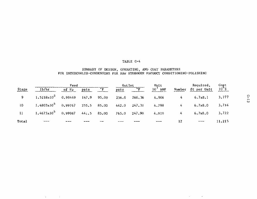
TABLE C-4
SUMMARY OF DESIGN, OPERATING, AND COST PARAMETERSFOR INTERCOOLER-CONDENSERS FOR RAW HYDROGEN PRODUCT CONDITIONING-POLISHING
Feed OutletStage lb/hr tnf H2 psia °F psia
9 1.5218xlO5 0.99449 147.9 95.00 256.0 260.36 4.906 4 6.7x8.1 3.777 ?h-•
10 J.48O3xlO5 0.99767 255.5 85.00 442.0 247.31
11 1.4675xlO5 0.99987 441.5 85.00 765.0 247.90
Total —
Unit10 BHP
4
4
4
.906
.798
.810
Number
4
4
4
12
Required,ft per Unit
6.7x8.1
6.7x8.0
6.7x8.0
Cost10 $
3.777
3.716
3.722
11.215
C-14
in the rav? H2 product is trapped by the scrubbing tower water. Two hundred
seventy-one vertical tubes, 4 feet long, 1 inch in diameter, made of SS-304, .
form the heat exchanger surface area of the evaporators per effect.
23.08.07 Final Hydrogen Product Drying Towers
Three drying towers are used to desiccate the final wet H2 products
subsequent to pressurized water scrubbing to eliminate any entrained radioactiv-
ity. While one unit is operating on stream, the second unit is undergoing des-
iccant regeneration, and the third is on standby. Molecular sieve beds are used
as the desiccant. The tower shell is made of SS-304, 104 in. i.d., 2.5 in. wall
thickness. Overall dimensions are 9.08-foot o.d. and 47 feet high. The desic-
cant volume is 2762 ft . The estimated cost of the molecular sieves is based on
3$223/ft . Auxiliary costs are assumed to be 7% of the cost of one tower.
23.08.08 High Temperature Electrolyz&rs
The high-temperature electrolyzers consist of 28 units. The electro-
2lyzers were designed based on a current density of 0.5 A/cm and a resistance of
3.07iVtube. Each electrolyzer cell is 1 cm long; 125 cells make up a tube.
2There are 225,360 tubes per unit. The electrolyzer area per cell is 4.442 cm .
The tubes are 1.56 m long and four lenghts are fitted into the overall HTE. The
tubes have 1.438 cm o.d. and 1 an i.d. The overall dimensions of each unit are
6 o.d. x 19.5 m high and 8.9 cm wall thickness.
The cost estimates for the electrolyzers were based on materials costs and
fabrication costs. The materials costs were based on large quantity purchases
of the individual materials (adjusted 1982 Alpha prices). The amount of each
type of material and the costing basis are tabulated in Table C-5.

C-15
TABLE C-5
SUMMARY OF MATERIALS COSTS PER HTE
Material
ZrO2
Y2O3
LaaO3
Cr2O3
A12O3
NCO
PrO2
Amount
Required,
1.7370 x
3.1070 x
1.7476 x
5.8253 x
3.8833 x
1.4563 x
2.3301 x
kg
105
103
103
102
105
10"
103
Cost Per Unit
Mass, kg
4.00
97.33
15.00
5.00
5.33
11.00
136.00
Material
6.95 x
3.0240
2.6195
2.9127
2.0698
1.6019
3.1689
Cost, $
105
x 105
x 104
x 103
x 105
x 105
x 105
Total Oxide Materials' Costs
Oxide Tube Fabrication Cost
HTE Shell Cost
Total Cost/HTE Unit
Total HTE Cost (28 Units)
2.
0.
4.
7.
216.
33
883
62
73
44
X
X
X
X
X
10
10
106
106
106