FUSION TECHNOLOGY - · ITER Interim Structural Design Criteria ... avoid copper coating damage but...
68
Transcript of FUSION TECHNOLOGY - · ITER Interim Structural Design Criteria ... avoid copper coating damage but...
FUSION TECHNOLOGY
Annual Report of the Association CEA/EURATOM
1999
Compiled by : Ph. MAGAUD
ASSOCIATION CEA/EURATOM DSM/DRFC
CEA CADARACHE 13108 Saint-Paul-Lez-Durance (France)
Tél. : 33 - 4 42 25 46 59 Fax : 33 - 4 42 25 64 21 e-mail : [email protected]
Cover : Carrier and bore tools for 4" bend pipes
Long term programme / European blanket project - 84 -
WP-A2-1 Task Title : TEST BLANKET MODULE ADAPTATION TO NEXT STEP Minimum requirements on Next Step for TBM testing INTRODUCTION The change of specifications of ITER-FDR as of summer 1998 to ITER-FEAT with significantly reduced cost and modified but yet unknown operation parameters necessitated a verification of the impact of the reactor parameters on the testing of a DEMO relevant Test Blanket Module of the Water-Cooled Lithium-Lead type (WCLL-TBM). In absence of clear specifications for the new machine ITER-FEAT, the response of a WCLL-TBM in different operating scenarios was studied to find an operating window in which testing remains meaningful.
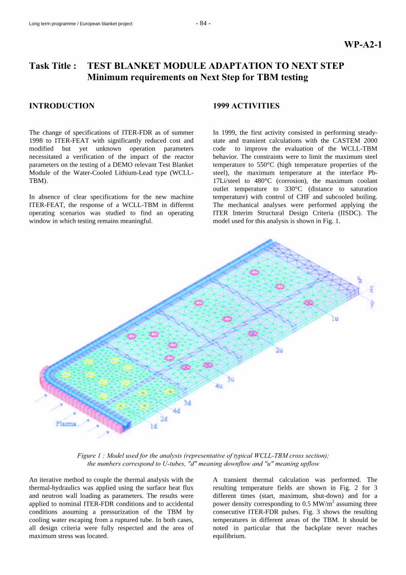
1999 ACTIVITIES In 1999, the first activity consisted in performing steady-state and transient calculations with the CASTEM 2000 code to improve the evaluation of the WCLL-TBM behavior. The constraints were to limit the maximum steel temperature to 550°C (high temperature properties of the steel), the maximum temperature at the interface Pb-17Li/steel to 480°C (corrosion), the maximum coolant outlet temperature to 330°C (distance to saturation temperature) with control of CHF and subcooled boiling. The mechanical analyses were performed applying the ITER Interim Structural Design Criteria (IISDC). The model used for this analysis is shown in Fig. 1.
Figure 1 : Model used for the analysis (representative of typical WCLL-TBM cross section); the numbers correspond to U-tubes, "d" meaning downflow and "u" meaning upflow
An iterative method to couple the thermal analysis with the thermal-hydraulics was applied using the surface heat flux and neutron wall loading as parameters. The results were applied to nominal ITER-FDR conditions and to accidental conditions assuming a pressurization of the TBM by cooling water escaping from a ruptured tube. In both cases, all design criteria were fully respected and the area of maximum stress was located.
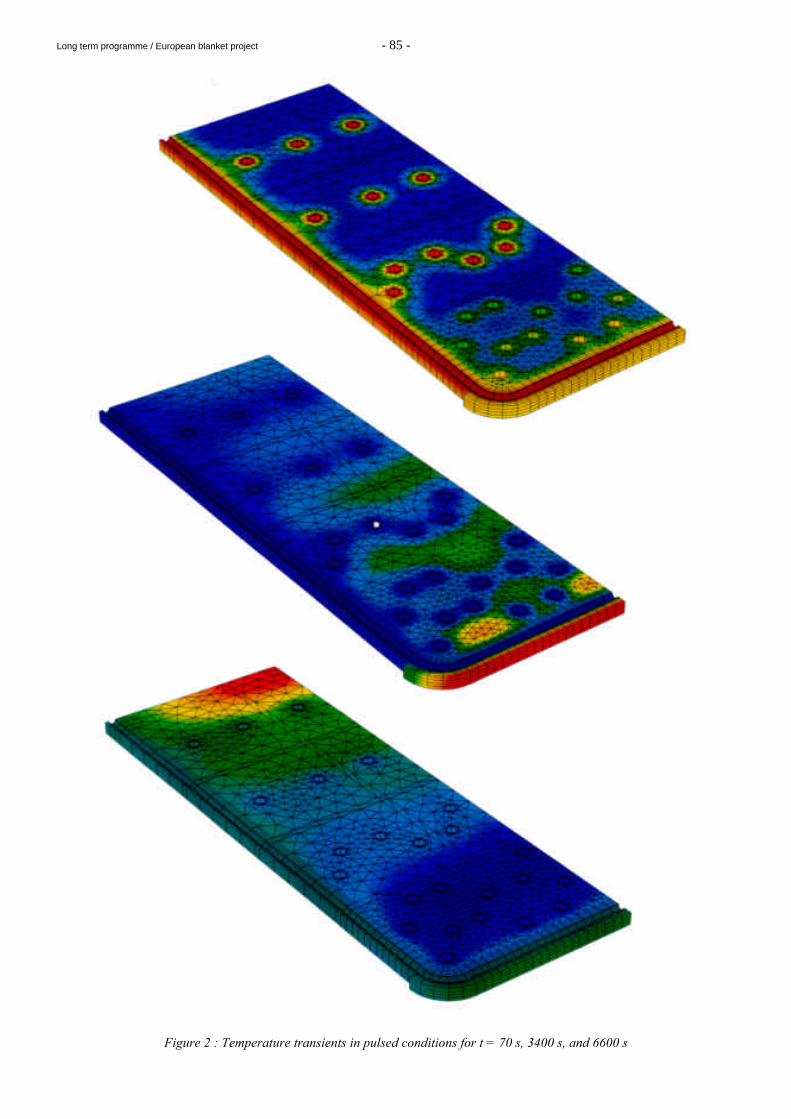
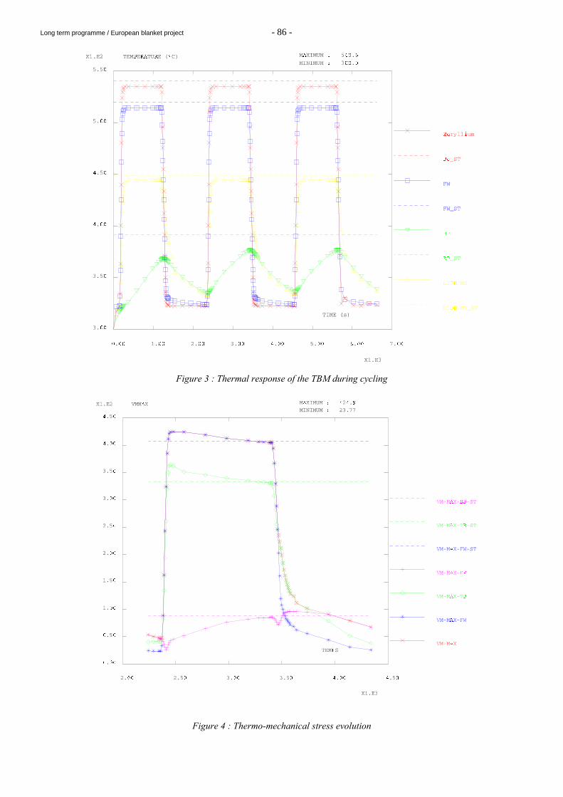
A transient thermal calculation was performed. The resulting temperature fields are shown in Fig. 2 for 3 different times (start, maximum, shut-down) and for a power density corresponding to 0.5 MW/m2 assuming three consecutive ITER-FDR pulses. Fig. 3 shows the resulting temperatures in different areas of the TBM. It should be noted in particular that the backplate never reaches equilibrium.
Long term programme / European blanket project - 85 -
Figure 2 : Temperature transients in pulsed conditions for t = 70 s, 3400 s, and 6600 s
Long term programme / European blanket project - 86 -
Figure 3 : Thermal response of the TBM during cycling
Figure 4 : Thermo-mechanical stress evolution
Long term programme / European blanket project - 87 -
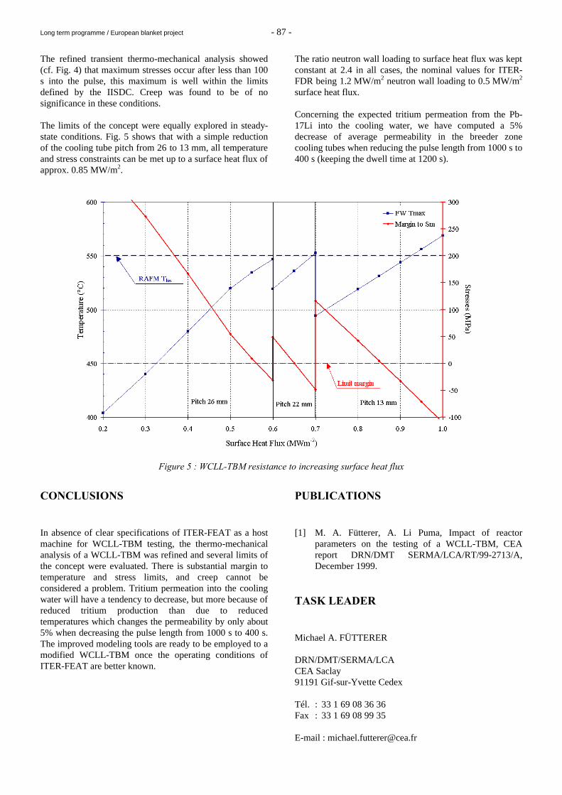
The refined transient thermo-mechanical analysis showed (cf. Fig. 4) that maximum stresses occur after less than 100 s into the pulse, this maximum is well within the limits defined by the IISDC. Creep was found to be of no significance in these conditions. The limits of the concept were equally explored in steady-state conditions. Fig. 5 shows that with a simple reduction of the cooling tube pitch from 26 to 13 mm, all temperature and stress constraints can be met up to a surface heat flux of approx. 0.85 MW/m2.
The ratio neutron wall loading to surface heat flux was kept constant at 2.4 in all cases, the nominal values for ITER-FDR being 1.2 MW/m2 neutron wall loading to 0.5 MW/m2 surface heat flux. Concerning the expected tritium permeation from the Pb-17Li into the cooling water, we have computed a 5% decrease of average permeability in the breeder zone cooling tubes when reducing the pulse length from 1000 s to 400 s (keeping the dwell time at 1200 s).
Figure 5 : WCLL-TBM resistance to increasing surface heat flux
CONCLUSIONS In absence of clear specifications of ITER-FEAT as a host machine for WCLL-TBM testing, the thermo-mechanical analysis of a WCLL-TBM was refined and several limits of the concept were evaluated. There is substantial margin to temperature and stress limits, and creep cannot be considered a problem. Tritium permeation into the cooling water will have a tendency to decrease, but more because of reduced tritium production than due to reduced temperatures which changes the permeability by only about 5% when decreasing the pulse length from 1000 s to 400 s. The improved modeling tools are ready to be employed to a modified WCLL-TBM once the operating conditions of ITER-FEAT are better known.
PUBLICATIONS [1] M. A. Fütterer, A. Li Puma, Impact of reactor
parameters on the testing of a WCLL-TBM, CEA report DRN/DMT SERMA/LCA/RT/99-2713/A, December 1999.
TASK LEADER Michael A. FÜTTERER DRN/DMT/SERMA/LCA CEA Saclay 91191 Gif-sur-Yvette Cedex Tél. : 33 1 69 08 36 36 Fax : 33 1 69 08 99 35 E-mail : [email protected]
Long term programme / European blanket project - 88 -
WP-A2-2.1 Task Title : TEST BLANKET MODULE ADAPTATION TO NEXT STEP Generic design modifications to reduce TBM size:
reduction of header space INTRODUCTION The envisaged cost restrictions for ITER-FDR supposedly lead to a machine that will offer more restricted space for the irradiation testing of Test Blanket Modules (TBM). In absence of clear specifications of this new machine, generic design modifications for the Water-Cooled Lithium-Lead TBM were developed to maximize the useful test volume while minimizing the test space requirements.
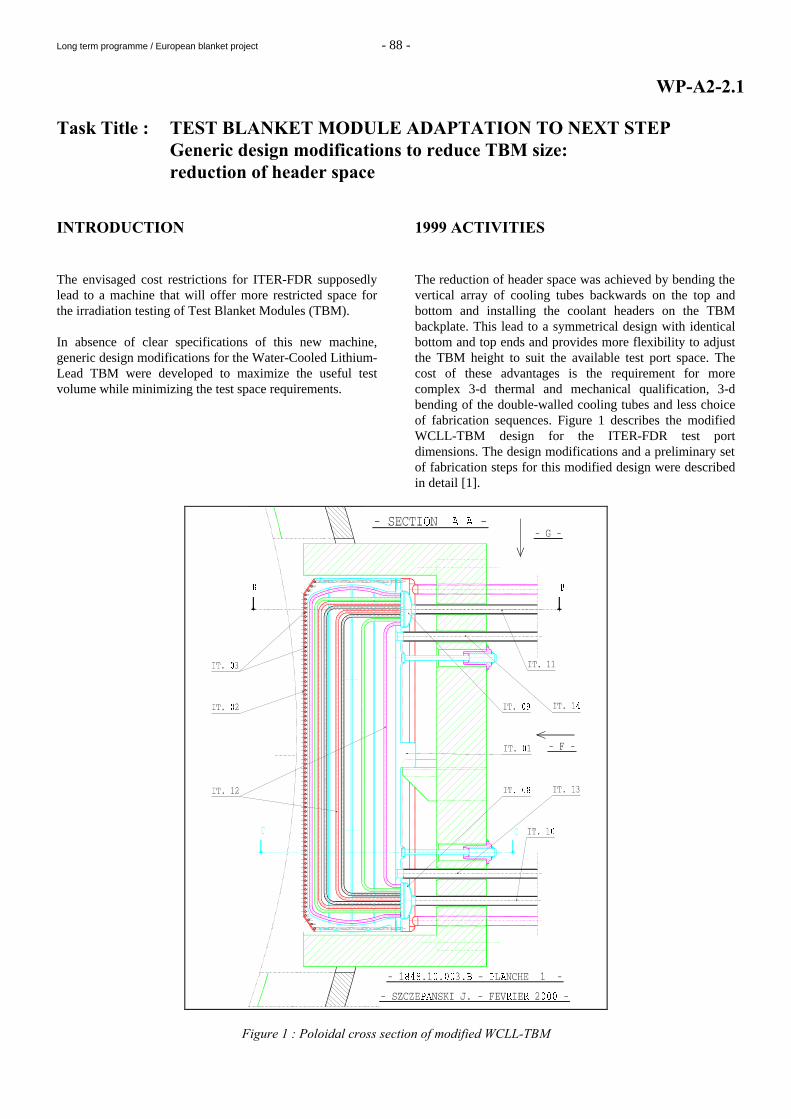
1999 ACTIVITIES The reduction of header space was achieved by bending the vertical array of cooling tubes backwards on the top and bottom and installing the coolant headers on the TBM backplate. This lead to a symmetrical design with identical bottom and top ends and provides more flexibility to adjust the TBM height to suit the available test port space. The cost of these advantages is the requirement for more complex 3-d thermal and mechanical qualification, 3-d bending of the double-walled cooling tubes and less choice of fabrication sequences. Figure 1 describes the modified WCLL-TBM design for the ITER-FDR test port dimensions. The design modifications and a preliminary set of fabrication steps for this modified design were described in detail [1].
Figure 1 : Poloidal cross section of modified WCLL-TBM
Long term programme / European blanket project - 89 -
CONCLUSIONS On the basis of the water-cooled lithium-lead Test Blanket Module (WCLL-TBM) designed for ITER-FDR specifications, design modifications were performed to make optimum use of the presumably reduced test port space of ITER-FEAT. More work is required to adapt this modified design to the new specifications of the host machine and thermomechanical analysis is needed to verify the stability of the TBM. PUBLICATIONS [1] M. A. Fütterer, J. Szczepanski, J.-F. Salavy, A. Li
Puma, Design modifications of the WCLL Test Blanket Module for ITER: Reduction of header space, CEA report DRN/DMT SERMA/LCA/RT/00-2761/A, February 2000.
TASK LEADER Michael A. Fütterer DRN/DMT/SERMA CEA Saclay 91191 Gif-sur-Yvette Cedex Tél. : 33 1 69 08 36 36 Fax : 33 1 69 08 99 35 E-mail : [email protected]
Long term programme / European blanket project - 90 -
WP-A3-1 Task Title : SOLID HIP DEMONSTRATOR FABRICATION AND COATING INTRODUCTION The fabrication of WCLL blanket modules using solid HIP technology is challenging. The blanket geometry is complex and it necessitates numerous steps and controls until achievement. The fabrication of subcomponents mock-ups and their integration in a bigger blanket mock up helps in identifying the successive operations, controls and difficulties. The fabrication of double wall tube (DWT) mock-ups designed to be tested under relevant conditions and their post test control and characterisation is another important work for WCLL technology. Least, the connection of the ferritic-martensitic modules to the stainless steel fluid supplying pipes requires heterogeneous joints that can be fabricated by HIP diffusion welded provided that the metallurgical compatibility is insured. 1999 ACTIVITIES DEFINITION OF A BLANKET DEMONSTRATOR MOCK UP The demonstrator shall prove the technological feasibility of a water-cooled lithium lead blanket using HIP diffusion welding process (HIP-DW). Detailed designs are given in [1] for the ITER test blanket module. In this work, the reference fabrication route of the ITER-TBM has been detailed in order to identify potential difficulties. Two specific points have been selected for further investigations : - First wall manufacturing : this component has never
been fabricated using HIP-DW. The U shape curvature of the cover sheet and the tubes is an important difficulty. The stacking gaps must be large enough to avoid copper coating damage but small enough to insure minimum distortion during HIPing.
- DWT/plate attachment : the DWT/plate welds are
critical for the safety point of view. In this region of the module, no double confinement exists.
To further define the demonstrator and its manufacturing route, two mock-ups have been defined corresponding to the two above components. The first wall mock up includes two U-bent grooved plates and a set of copper-coated tubes in-between. The whole is joined by HIP-DW. This mock up is still under fabrication.
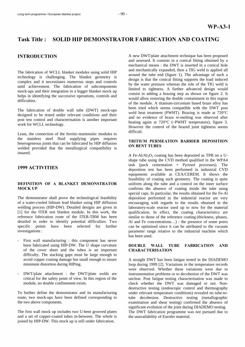
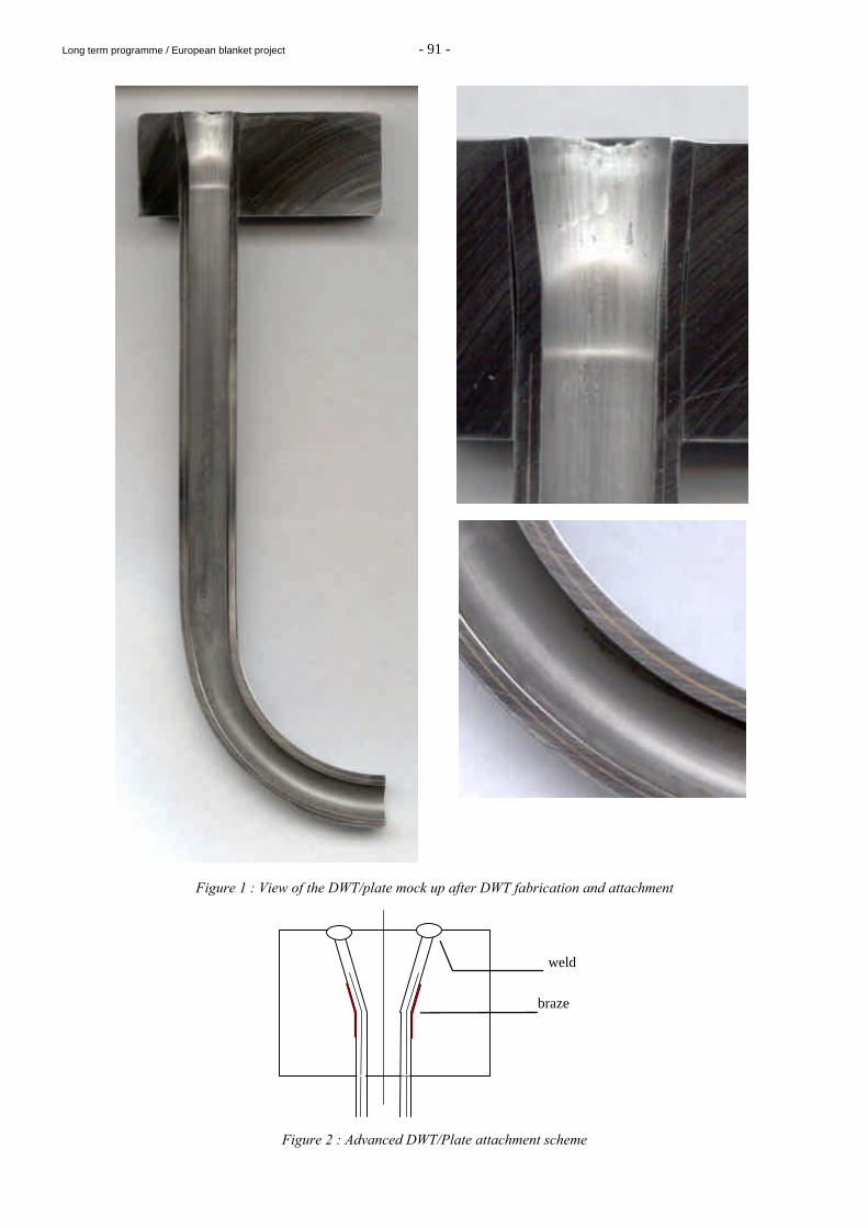
A new DWT/plate attachment technique has been proposed and assessed. It consists in a conical fitting obtained by a mechanical means : the DWT is inserted in a conical hole and mechanically expanded, then a TIG weld is applied all around the tube end (figure 1). The advantage of such a design is that the conical fitting supports the load induced by the water pressure whereas the role of the TIG weld is limited to tightness. A further advanced design would consist in adding a brazing step as shown on figure 2. It would allow restoring the double containment in this region of the module. A titanium-zirconium based braze alloy has been tried which seems compatible with the DWT post weld heat treatment (PWHT). Brazing is made at 720°C and no evidence of braze re-melting was observed after heating again at 720°C (~PWHT temperature), figure 3. However the control of the brazed joint tightness seems difficult. TRITIUM PERMEATION BARRIER DEPOSITION ON BENT TUBES A Fe-Al/Al2O3 coating has been deposited as TPB on a U-shape tube using the CVD method qualified in the WPA4 task (pack cementation + Pyrosol processes). The deposition test has been performed in industrial CVD equipments available at CEA/CEREM. It shows the feasibility of coating such geometry. The coating is quite uniform along the tube and a control on the inner surface confirms the absence of coating inside the tube using special caps. In particular, the results obtained for the Fe-Al deposition performed in the industrial reactor are very encouraging with regards to the results obtained in the laboratory-scale reactor used up to now for the material qualification. In effect, the coating characteristics are similar to those of the reference coating (thickness, phases, Al and Fe concentrations…) : the presence of some pores can be optimised since it can be attributed to the vacuum parameter range relative to the industrial machine which has been used. DOUBLE WALL TUBE FABRICATION AND CHARACTERISATION A straight DWT has been fatigue tested in the DIADEMO loop during 1999 [2]. Variations in the temperature records were observed. Whether these variations were due to instrumentation problems or to decohesion of the DWT was unclear. Post fatigue testing characterisation was made to check whether the DWT was damaged or not. Non-destructive testing (endoscopic control and thermography under relevant temperature conditions) revealed no tube-to-tube decohesion. Destructive testing (metallographic examination and shear testing) confirmed the absence of significant evolution of the joint during DIADEMO testing. The DWT fabrication programme was not pursued due to the unavailability of Eurofer material.
Long term programme / European blanket project - 91 -
Figure 1 : View of the DWT/plate mock up after DWT fabrication and attachment
Figure 2 : Advanced DWT/Plate attachment scheme
weld
braze
Long term programme / European blanket project - 92 -
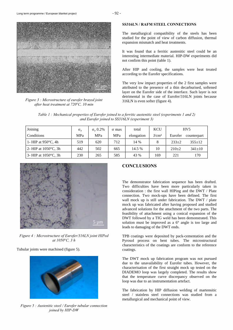
Figure 3 : Microstructure of eurofer brazed joint after heat treatment at 720°C, 10 min
SS316LN / RAFM STEEL CONNECTIONS The metallurgical compatibility of the steels has been studied for the point of view of carbon diffusion, thermal expansion mismatch and heat treatments. It was found that a ferritic austenitic steel could be an interesting intermediate material. HIP-DW experiments did not confirm this point (table 1). After HIP and cooling, the samples were heat treated according to the Eurofer specifications. The very low impact properties of the 2 first samples were attributed to the presence of a thin decarburised, softened layer on the Eurofer side of the interface. Such layer is not detrimental in the case of Eurofer/316LN joints because 316LN is even softer (figure 4).
Table 1 : Mechanical properties of Eurofer joined to a ferritic austenitic steel (experiments 1 and 2)
and Eurofer joined to SS316LN (experiment 3)
Joining σy σy 0.2% σ max total KCU HV5
Conditions MPa MPa MPa elongation J/cm² Eurofer counterpart
1- HIP at 950°C, 4h 519 620 712 14 % 8 233±2 355±12
2- HIP at 1050°C, 3h 442 502 665 14.5 % 10 210±2 341±10
3- HIP at 1050°C, 3h 230 265 585 43 % 169 221 170
Figure 4 : Microstructure of Eurofer/316LN joint HIPed at 1050°C, 3 h
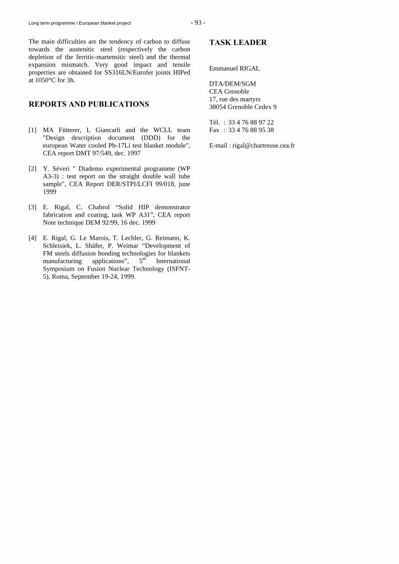
Tubular joints were machined (figure 5).
Figure 5 : Austenitic steel / Eurofer tubular connection joined by HIP-DW
CONCLUSIONS The demonstrator fabrication sequence has been drafted. Two difficulties have been more particularly taken in consideration : the first wall HIPing and the DWT / Plate connection. Two mock-ups have been defined. The first wall mock up is still under fabrication. The DWT / plate mock up was fabricated after having proposed and studied advanced solutions for the attachment of the two parts. The feasibility of attachment using a conical expansion of the DWT followed by a TIG weld has been demonstrated. This solution must be improved as a 6° angle is too large and leads to damaging of the DWT ends. TPB coatings were deposited by pack-cementation and the Pyrosol process on bent tubes. The microstructural characteristics of the coatings are conform to the reference coatings. The DWT mock up fabrication program was not pursued due to the unavailability of Eurofer tubes. However, the characterisation of the first straight mock up tested on the DIADEMO loop was largely completed. The results show that the temperature curve discrepancy observed on the loop was due to an instrumentation artefact. The fabrication by HIP diffusion welding of martensitic steel / stainless steel connections was studied from a metallurgical and mechanical point of view.
50 µm
5 µm
Long term programme / European blanket project - 93 -
The main difficulties are the tendency of carbon to diffuse towards the austenitic steel (respectively the carbon depletion of the ferritic-martensitic steel) and the thermal expansion mismatch. Very good impact and tensile properties are obtained for SS316LN/Eurofer joints HIPed at 1050°C for 3h. REPORTS AND PUBLICATIONS [1] MA Fütterer, L Giancarli and the WCLL team
"Design description document (DDD) for the european Water cooled Pb-17Li test blanket module", CEA report DMT 97/549, dec. 1997
[2] Y. Séveri " Diademo experimental programme (WP
A3-3) : test report on the straight double wall tube sample", CEA Report DER/STPI/LCFI 99/018, june 1999
[3] E. Rigal, C. Chabrol “Solid HIP demonstrator
fabrication and coating, task WP A31”, CEA report Note technique DEM 92/99, 16 dec. 1999
[4] E. Rigal, G. Le Marois, T. Lechler, G. Reimann, K.
Schleisiek, L. Shäfer, P. Weimar “Development of FM steels diffusion bonding technologies for blankets manufacturing applications”, 5th International Symposium on Fusion Nuclear Technology (ISFNT-5), Roma, September 19-24, 1999.
TASK LEADER Emmanuel RIGAL DTA/DEM/SGM CEA Grenoble 17, rue des martyrs 38054 Grenoble Cedex 9 Tél. : 33 4 76 88 97 22 Fax : 33 4 76 88 95 38 E-mail : [email protected]
Long term programme / European blanket project - 94 -
WP-A3-3 WP-A3-2.1
Task Title : DOUBLE-WALL TUBE OUT-OF-PILE TESTING Double-Wall tube testing (DIADEMO experimental program) INTRODUCTION Within the framework of the study on Water-Cooled Lithium-Lead tritigenous Blankets for a fusion reactor, technological choices on cooling tubes must be validated. Within this context, tests on Double-Wall Tubes (DWT's) through which reactor power will be transferred must be carried out. The state of the art technology of these tubes is of utmost importance as it conditions the concept and must be validated from both mechanical and thermal point of view. Before considering industrial manufacturing, samples have to be tested under fusion reactor nominal. The main objective of DIADEMO experimental device is to validate, in close collaboration with the task WP-A3-1 (Double-Wall tube fabrication), the choice of the double-walled tube for the future Fusion reactor. 1999 ACTIVITIES This task has been launched in 1996. Following that : - A preliminary feasibility study, concerning an
experimental device in order to test DWTs, has been performed by mid of 1996.
- A pre-design study has been, then, performed during the second half of 1996 in order to launch, beginning of 1997.
- A call for tender for the fabrication study.
- Following this fabrication study, a call for tender has been launched for the manufacturing of the mechanical part of the experimental device.
- In the mean time (summer 1997), a call for tender has been launched in order to perform the study and the manufacturing concerning the 'Instrumentation and Control' of the experimental device.
- The end of the year 97 and the year 98 have been devoted to the fabrication of the experimental device (mechanical part, instrumentation and control, thermal isolation).
- During the year 99, an experimental program have
been lead on a straight Double-Wall Tube (DWT) sample.
This task is performed in close collaboration with task WP-A3-1, driven by CEA/ CEREM, responsible of the fabrication of the DWTs (choice of the DWT fabrication procedure, DWT manufacturing). The first straight sample (length 500 mm, heated on 200 mm) has been manufactured by CEA/ CEREM during the first half of the year 98. It has been delivered to Cadarache during the SOFT period (11th, September). It has been hydraulically tested (up to 25 Mpa). The straight DWT sample has been fitted and prepared during the rest of September and installed on the DIADEMO test loop. The first test campaign started on April 14th and ended May 1st of 1999. RECALL OF THE EXPERIMENTAL DEVICE, DIADEMO. The experimental device "DIADEMO" has to satisfy to fusion reactor operating conditions. So the circuit has been designed for pulsed conditions (in order to perform thermal fatigue tests on the DWTs. 3000 thermal cycles are foreseen for the first mock-up) and for long time thermal steady-state operating conditions (in order to perform endurance tests). The final experimental device is as follow : Two test stations : i) the first one called "Air Test Station", using only the
pressurized water cooling circuit. The test samples are electrically heated (not use of Pb-17Li loop),
ii) the second one called "Pb-17Li Test Station", using the
entire circuit; the Pb-17Li being also electrically heated. The "Air Test Station" will be used for the small size tests samples. The "Pb-17Li Test Station" will be available for the final qualification of the DWT in presence of the eutectic. Lithium-Lead Loop The maximum operating temperature in the Pb-17Li is 550°C (Reactor operating condition in the blanket). Nevertheless it will be possible to perform thermal transients in the liquid metal for Reactor pulsed operating conditions. The operating temperatures in this case will be between 300 and 390°C.
Long term programme / European blanket project - 95 -
Primary Water Cooling Loop The operating conditions of the primary water cooling circuit will simulate reactor conditions : - Maximum water temperature : 325°C, - Minimum water temperature : 265°C, - Water pressure : 15.5 MPa, - Water tube flow rate : 0.37 kg/s. The "Air Test Station" is in fact a derivation on the main water loop. The test samples will be connected to the water cooling loop with flanges and externally electrically heated. It is forecasted to test on this station small size samples (straight and bent).
DESCRIPTION OF THE SAMPLE. The first Double-Wall Tube muck-up material is martensitic steel (T91). The length of the mock-up is 470 mm (but heated on 200 mm length). The inner tube dimensions are 11x13.5 mm ; the outer tube dimensions are 14x16.8 mm (after HIPping). The inner tube has been coated by electroplating with copper on the outer surface. The deposited pure copper layer has a thickness between 0.15 - 0.20 mm. In order to weld the DWT mock-up to austenitic steel flanges, the tube were equiped with austenitic tubular connections (304 L stainless steel ends and the DWT were diffusion welded simultaneously).
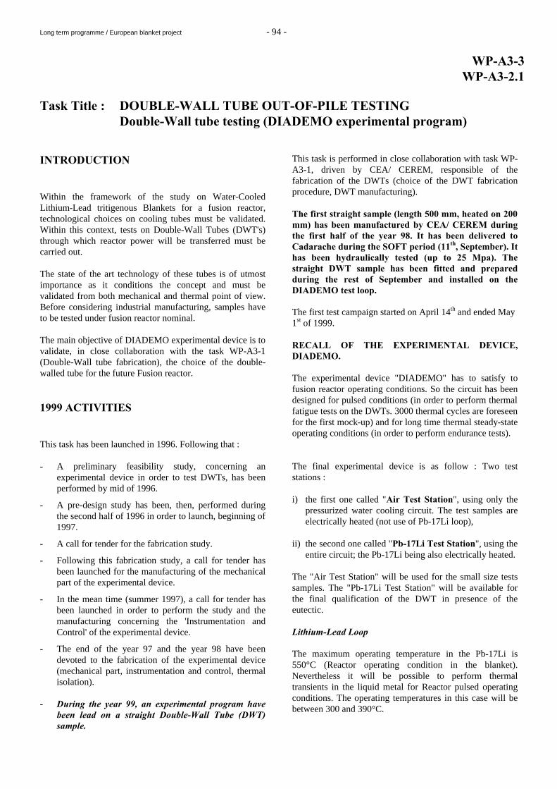
The following sketch and the figure 1 show the thermocouple instrumentation performed on the DWT test mock-up. Six thermocouples of 0.5 mm diameter are located on the surface of the external tube. They are located on two sections (3 thermocouples per section) spaced by 80 mm. They are symmetrically located versus the middle of the tube. It has not been possible to braze the thermocouples in the external tube thickness (specification given by the Double-Wall tube manufacturer), in order to measure the real temperature of the external envelope. For this reason, the thermocouples are put on the external wall and covered by a little piece of stainless steel welded on the surface : this solution can induce uncertainties on temperature measurements because the measure is between DWT and heaters.
Thermocouple
Cylindrical electrical Heater
Graphite Block
Tube
200 mm
40 mm 40 mm
Electrical heater
Figure 1 : Tube mock-up instrumentation sketch
TEST CAMPAIGN. The objective of the test campaign was to perform 3000 thermal cycles on the external wall of the Double-Wall tube specimen. The main characteristics of the test were the following : - Primary water pressure : 15.5 Mpa, - Inlet water temperature in the mock-up : 300°C,
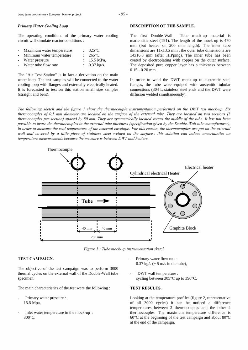
- Primary water flow rate : 0.37 kg/s (~ 5 m/s in the tube), - DWT wall temperature : cycling between 305°C up to 390°C. TEST RESULTS. Looking at the temperature profiles (figure 2, representative of all 3000 cycles) it can be noticed a difference temperatures between 2 thermocouples and the other 4 thermocouples. The maximum temperature difference is 60°C at the beginning of the test campaign and about 80°C at the end of the campaign.
Long term programme / European blanket project - 96 -
Figure 2 : Representative temperature profile on the first Tube wall mock-up
This can be explained by the fact, previously mentioned, that the thermal contact between the thermocouples and the wall tube is probably not good. The thermocouples which indicate temperatures above 400°C (TCM2, TCM1) are influenced by the graphite block (heated by the electrical heater). Finally it can be noticed a time duration increase between the thermal cycle (mainly during the cooling phase). This fact is probably due to the same previous reason : the improve thermal contact between the graphite block and the tube.
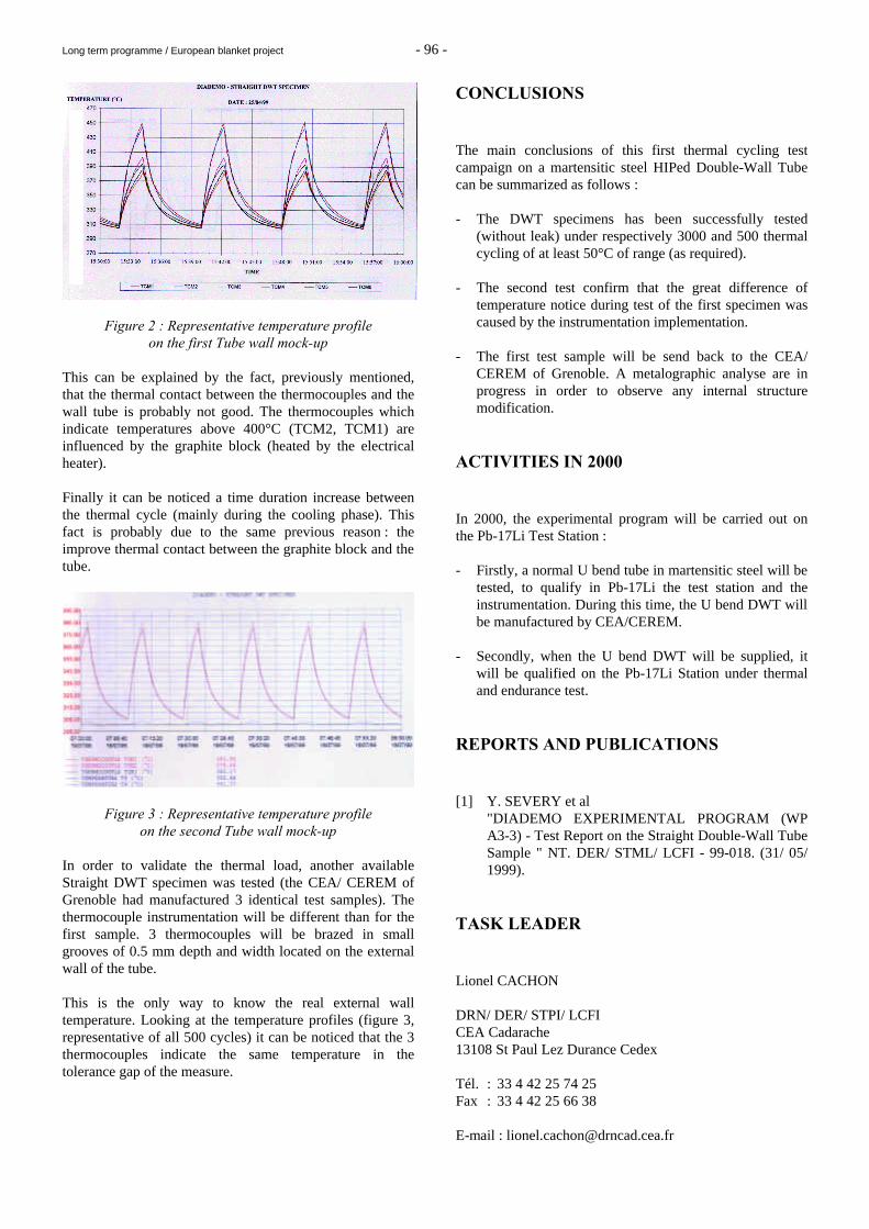
Figure 3 : Representative temperature profile on the second Tube wall mock-up
In order to validate the thermal load, another available Straight DWT specimen was tested (the CEA/ CEREM of Grenoble had manufactured 3 identical test samples). The thermocouple instrumentation will be different than for the first sample. 3 thermocouples will be brazed in small grooves of 0.5 mm depth and width located on the external wall of the tube. This is the only way to know the real external wall temperature. Looking at the temperature profiles (figure 3, representative of all 500 cycles) it can be noticed that the 3 thermocouples indicate the same temperature in the tolerance gap of the measure.
CONCLUSIONS The main conclusions of this first thermal cycling test campaign on a martensitic steel HIPed Double-Wall Tube can be summarized as follows : - The DWT specimens has been successfully tested
(without leak) under respectively 3000 and 500 thermal cycling of at least 50°C of range (as required).
- The second test confirm that the great difference of
temperature notice during test of the first specimen was caused by the instrumentation implementation.
- The first test sample will be send back to the CEA/
CEREM of Grenoble. A metalographic analyse are in progress in order to observe any internal structure modification.
ACTIVITIES IN 2000 In 2000, the experimental program will be carried out on the Pb-17Li Test Station : - Firstly, a normal U bend tube in martensitic steel will be
tested, to qualify in Pb-17Li the test station and the instrumentation. During this time, the U bend DWT will be manufactured by CEA/CEREM.
- Secondly, when the U bend DWT will be supplied, it
will be qualified on the Pb-17Li Station under thermal and endurance test.
REPORTS AND PUBLICATIONS [1] Y. SEVERY et al "DIADEMO EXPERIMENTAL PROGRAM (WP
A3-3) - Test Report on the Straight Double-Wall Tube Sample " NT. DER/ STML/ LCFI - 99-018. (31/ 05/ 1999).
TASK LEADER
Lionel CACHON DRN/ DER/ STPI/ LCFI CEA Cadarache 13108 St Paul Lez Durance Cedex Tél. : 33 4 42 25 74 25 Fax : 33 4 42 25 66 38 E-mail : [email protected]
Long term programme / European blanket project - 97 -
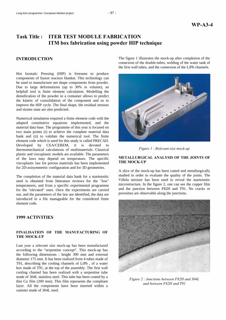
WP-A3-4 Task Title : ITER TEST MODULE FABRICATION ITM box fabrication using powder HIP technique INTRODUCTION Hot Isostatic Pressing (HIP) is foreseen to produce components of fusion reactors blanket. This technology can be used to manufacture net shape components from powder. Due to large deformations (up to 30% in volume), an helpfull tool is finite element calculation. Modelling the densification of the powder in a container allows to predict the kinetic of consolidation of the component and so to improve the HIP cycle. The final shape, the residual stresses and strains state are also predicted. Numerical simulation required a finite element code with the adapted constitutive equations implemented, and the material data base. The programme of this year is focused on two main points (i) to achieve the complete material data bank and (ii) to validate the numerical tool. The finite element code which is used for this study is called PRECAD. Developed by CEA/CEREM, it is devoted to thermomechanical calculations of multimaterials. Classical plastic and viscoplastic models are available. The parameters of the laws may depend on temperature. The specific viscoplastic law for porous materials has been implemented for 2D-axisymmetric configuration and for 3D geometries. The completion of the material data bank for a martensitic steel is obtained from litterature reviews for the "low" temperatures, and from a specific experimental programme for the "elevated" ones. Once the experiments are carried out, and the parameters of the law are identified, the data are introduced in a file manageable for the considered finite element code. 1999 ACTIVITIES FINALISATION OF THE MANUFACTURING OF THE MOCK-UP Last year a relevant size mock-up has been manufactured according to the “serpentine concept”. This mock-up has the following dimensions : height 390 mm and external diameter 175 mm. It has been realized from 4 tubes made of T91, describing the cooling channels of LiPb , of a water box made of T91, at the top of the assembly. The first wall cooling channel has been realized with a serpentine tube made of 304L stainless steel. This tube has been coated by a thin Cu film (200 mm). This film represents the compliant layer. All the components have been inserted within a canister made of 304L steel.
The figure 1 illustrates the mock-up after completion of the connexion of the double-tubes, welding of the water tank of the first wall tubes, and the connexion of the LiPb channels.
Figure 1 : Relevant-size mock-up METALLURGICAL ANALYSIS OF THE JOINTS OF THE MOCK-UP A slice of the mock-up has been cutted and metallurgically studied in order to evaluate the quality of the joints. The Villela mixture has been used to reveal the martensitic microstructure. In the figure 2, one can see the copper film and the junction between F82H and T91. No cracks or porosities are observable along the junctions.
Figure 2 : Junctions between F82H and 304L and between F82H and T91
Long term programme / European blanket project - 98 -
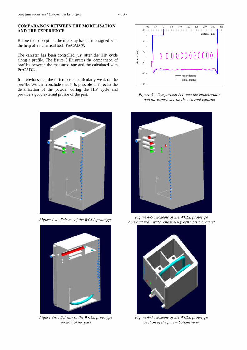
COMPARAISON BETWEEN THE MODELISATION AND THE EXPERIENCE Before the conception, the mock-up has been designed with the help of a numerical tool: PreCAD ®. The canister has been controlled just after the HIP cycle along a profile. The figure 3 illustrates the comparison of profiles between the measured one and the calculated with PreCAD®. It is obvious that the difference is particularly weak on the profile. We can conclude that it is possible to forecast the densification of the powder during the HIP cycle and provide a good external profile of the part.
-100
-90
-80
-70
-60
-50
-100 -50 0 50 100 150 200 250 300 350
distance (mm)
dist
ance
(m
m)
mesured profile
calculed profile
Figure 3 : Comparison between the modelisation and the experience on the external canister
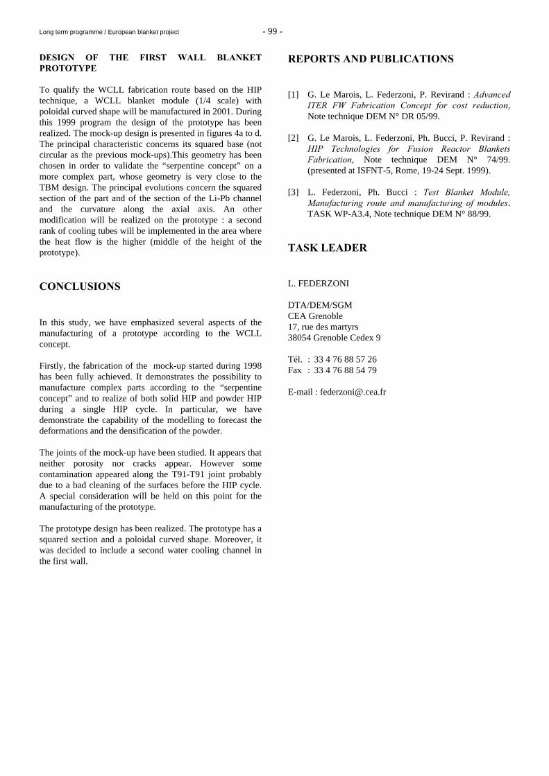
Figure 4-a : Scheme of the WCLL prototype Figure 4-b : Scheme of the WCLL prototype
blue and red : water channels-green : LiPb channel
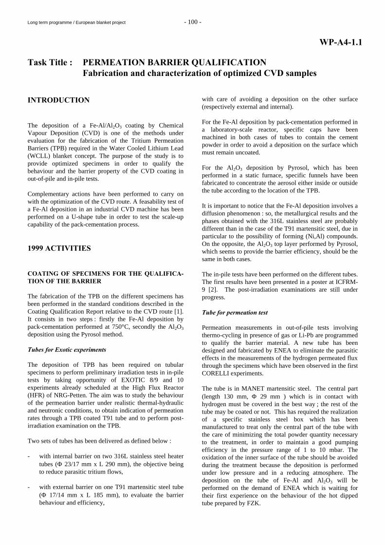
Figure 4-c : Scheme of the WCLL prototype
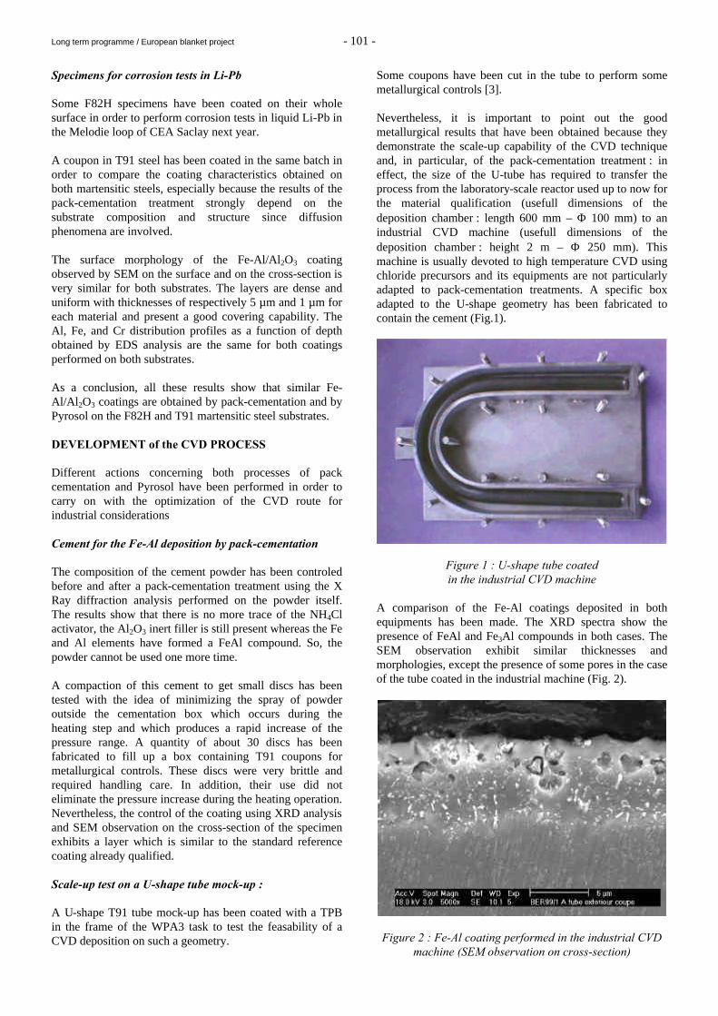
section of the part Figure 4-d : Scheme of the WCLL prototype
section of the part – bottom view
Long term programme / European blanket project - 99 -
DESIGN OF THE FIRST WALL BLANKET PROTOTYPE To qualify the WCLL fabrication route based on the HIP technique, a WCLL blanket module (1/4 scale) with poloidal curved shape will be manufactured in 2001. During this 1999 program the design of the prototype has been realized. The mock-up design is presented in figures 4a to d. The principal characteristic concerns its squared base (not circular as the previous mock-ups).This geometry has been chosen in order to validate the “serpentine concept” on a more complex part, whose geometry is very close to the TBM design. The principal evolutions concern the squared section of the part and of the section of the Li-Pb channel and the curvature along the axial axis. An other modification will be realized on the prototype : a second rank of cooling tubes will be implemented in the area where the heat flow is the higher (middle of the height of the prototype). CONCLUSIONS In this study, we have emphasized several aspects of the manufacturing of a prototype according to the WCLL concept. Firstly, the fabrication of the mock-up started during 1998 has been fully achieved. It demonstrates the possibility to manufacture complex parts according to the “serpentine concept” and to realize of both solid HIP and powder HIP during a single HIP cycle. In particular, we have demonstrate the capability of the modelling to forecast the deformations and the densification of the powder. The joints of the mock-up have been studied. It appears that neither porosity nor cracks appear. However some contamination appeared along the T91-T91 joint probably due to a bad cleaning of the surfaces before the HIP cycle. A special consideration will be held on this point for the manufacturing of the prototype. The prototype design has been realized. The prototype has a squared section and a poloidal curved shape. Moreover, it was decided to include a second water cooling channel in the first wall.
REPORTS AND PUBLICATIONS [1] G. Le Marois, L. Federzoni, P. Revirand : Advanced
ITER FW Fabrication Concept for cost reduction, Note technique DEM N° DR 05/99.
[2] G. Le Marois, L. Federzoni, Ph. Bucci, P. Revirand :
HIP Technologies for Fusion Reactor Blankets Fabrication, Note technique DEM N° 74/99. (presented at ISFNT-5, Rome, 19-24 Sept. 1999).
[3] L. Federzoni, Ph. Bucci : Test Blanket Module,
Manufacturing route and manufacturing of modules. TASK WP-A3.4, Note technique DEM N° 88/99.
TASK LEADER L. FEDERZONI DTA/DEM/SGM CEA Grenoble 17, rue des martyrs 38054 Grenoble Cedex 9 Tél. : 33 4 76 88 57 26 Fax : 33 4 76 88 54 79 E-mail : [email protected]
Long term programme / European blanket project - 100 -
WP-A4-1.1 Task Title : PERMEATION BARRIER QUALIFICATION Fabrication and characterization of optimized CVD samples INTRODUCTION The deposition of a Fe-Al/Al2O3 coating by Chemical Vapour Deposition (CVD) is one of the methods under evaluation for the fabrication of the Tritium Permeation Barriers (TPB) required in the Water Cooled Lithium Lead (WCLL) blanket concept. The purpose of the study is to provide optimized specimens in order to qualify the behaviour and the barrier property of the CVD coating in out-of-pile and in-pile tests. Complementary actions have been performed to carry on with the optimization of the CVD route. A feasability test of a Fe-Al deposition in an industrial CVD machine has been performed on a U-shape tube in order to test the scale-up capability of the pack-cementation process. 1999 ACTIVITIES COATING OF SPECIMENS FOR THE QUALIFICA-TION OF THE BARRIER The fabrication of the TPB on the different specimens has been performed in the standard conditions described in the Coating Qualification Report relative to the CVD route [1]. It consists in two steps : firstly the Fe-Al deposition by pack-cementation performed at 750°C, secondly the Al2O3 deposition using the Pyrosol method. Tubes for Exotic experiments The deposition of TPB has been required on tubular specimens to perform preliminary irradiation tests in in-pile tests by taking opportunity of EXOTIC 8/9 and 10 experiments already scheduled at the High Flux Reactor (HFR) of NRG-Petten. The aim was to study the behaviour of the permeation barrier under realistic thermal-hydraulic and neutronic conditions, to obtain indication of permeation rates through a TPB coated T91 tube and to perform post-irradiation examination on the TPB. Two sets of tubes has been delivered as defined below : - with internal barrier on two 316L stainless steel heater
tubes (Φ 23/17 mm x L 290 mm), the objective being to reduce parasitic tritium flows,
- with external barrier on one T91 martensitic steel tube
(Φ 17/14 mm x L 185 mm), to evaluate the barrier behaviour and efficiency,
with care of avoiding a deposition on the other surface (respectively external and internal). For the Fe-Al deposition by pack-cementation performed in a laboratory-scale reactor, specific caps have been machined in both cases of tubes to contain the cement powder in order to avoid a deposition on the surface which must remain uncoated. For the Al2O3 deposition by Pyrosol, which has been performed in a static furnace, specific funnels have been fabricated to concentrate the aerosol either inside or outside the tube according to the location of the TPB. It is important to notice that the Fe-Al deposition involves a diffusion phenomenon : so, the metallurgical results and the phases obtained with the 316L stainless steel are probably different than in the case of the T91 martensitic steel, due in particular to the possibility of forming (Ni,Al) compounds. On the opposite, the Al2O3 top layer performed by Pyrosol, which seems to provide the barrier efficiency, should be the same in both cases. The in-pile tests have been performed on the different tubes. The first results have been presented in a poster at ICFRM-9 [2]. The post-irradiation examinations are still under progress. Tube for permeation test Permeation measurements in out-of-pile tests involving thermo-cycling in presence of gas or Li-Pb are programmed to qualify the barrier material. A new tube has been designed and fabricated by ENEA to eliminate the parasitic effects in the measurements of the hydrogen permeated flux through the specimens which have been observed in the first CORELLI experiments. The tube is in MANET martensitic steel. The central part (length 130 mm, Φ 29 mm ) which is in contact with hydrogen must be covered in the best way ; the rest of the tube may be coated or not. This has required the realization of a specific stainless steel box which has been manufactured to treat only the central part of the tube with the care of minimizing the total powder quantity necessary to the treatment, in order to maintain a good pumping efficiency in the pressure range of 1 to 10 mbar. The oxidation of the inner surface of the tube should be avoided during the treatment because the deposition is performed under low pressure and in a reducing atmosphere. The deposition on the tube of Fe-Al and Al2O3 will be performed on the demand of ENEA which is waiting for their first experience on the behaviour of the hot dipped tube prepared by FZK.
Long term programme / European blanket project - 101 -
Specimens for corrosion tests in Li-Pb Some F82H specimens have been coated on their whole surface in order to perform corrosion tests in liquid Li-Pb in the Melodie loop of CEA Saclay next year. A coupon in T91 steel has been coated in the same batch in order to compare the coating characteristics obtained on both martensitic steels, especially because the results of the pack-cementation treatment strongly depend on the substrate composition and structure since diffusion phenomena are involved. The surface morphology of the Fe-Al/Al2O3 coating observed by SEM on the surface and on the cross-section is very similar for both substrates. The layers are dense and uniform with thicknesses of respectively 5 µm and 1 µm for each material and present a good covering capability. The Al, Fe, and Cr distribution profiles as a function of depth obtained by EDS analysis are the same for both coatings performed on both substrates. As a conclusion, all these results show that similar Fe-Al/Al2O3 coatings are obtained by pack-cementation and by Pyrosol on the F82H and T91 martensitic steel substrates. DEVELOPMENT of the CVD PROCESS Different actions concerning both processes of pack cementation and Pyrosol have been performed in order to carry on with the optimization of the CVD route for industrial considerations Cement for the Fe-Al deposition by pack-cementation The composition of the cement powder has been controled before and after a pack-cementation treatment using the X Ray diffraction analysis performed on the powder itself. The results show that there is no more trace of the NH4Cl activator, the Al2O3 inert filler is still present whereas the Fe and Al elements have formed a FeAl compound. So, the powder cannot be used one more time. A compaction of this cement to get small discs has been tested with the idea of minimizing the spray of powder outside the cementation box which occurs during the heating step and which produces a rapid increase of the pressure range. A quantity of about 30 discs has been fabricated to fill up a box containing T91 coupons for metallurgical controls. These discs were very brittle and required handling care. In addition, their use did not eliminate the pressure increase during the heating operation. Nevertheless, the control of the coating using XRD analysis and SEM observation on the cross-section of the specimen exhibits a layer which is similar to the standard reference coating already qualified. Scale-up test on a U-shape tube mock-up : A U-shape T91 tube mock-up has been coated with a TPB in the frame of the WPA3 task to test the feasability of a CVD deposition on such a geometry.
Some coupons have been cut in the tube to perform some metallurgical controls [3]. Nevertheless, it is important to point out the good metallurgical results that have been obtained because they demonstrate the scale-up capability of the CVD technique and, in particular, of the pack-cementation treatment : in effect, the size of the U-tube has required to transfer the process from the laboratory-scale reactor used up to now for the material qualification (usefull dimensions of the deposition chamber : length 600 mm – Φ 100 mm) to an industrial CVD machine (usefull dimensions of the deposition chamber : height 2 m – Φ 250 mm). This machine is usually devoted to high temperature CVD using chloride precursors and its equipments are not particularly adapted to pack-cementation treatments. A specific box adapted to the U-shape geometry has been fabricated to contain the cement (Fig.1).
Figure 1 : U-shape tube coated in the industrial CVD machine
A comparison of the Fe-Al coatings deposited in both equipments has been made. The XRD spectra show the presence of FeAl and Fe3Al compounds in both cases. The SEM observation exhibit similar thicknesses and morphologies, except the presence of some pores in the case of the tube coated in the industrial machine (Fig. 2).
Figure 2 : Fe-Al coating performed in the industrial CVD
machine (SEM observation on cross-section)
Long term programme / European blanket project - 102 -
The formation of these pores could be explained by the higher pressure level obtained in this machine (45 mbar instead of 1-10 mbar in the laboratory-scale equipment). Nevertheless, the distribution profiles of Al, Fe and Cr obtained as a function of depth using EDS analysis are also very comparable . From scale-up considerations, these results are very encouraging for a first trial, because they show that the pack-cementation process can be transfered from one equipment to another one with good metallurgical characteristics. Choice of precursor for the alumina deposition by Pyrosol : The use of another metalorganic precursor has been tested for the alumina deposition : the solution has been prepared starting from aluminum acetylacetonate with methanol as solvent, instead of aluminum-iso-propoxide with acetylacetone as solvent. In this case, the deposition temperature can be lowered from 450-400°C down to 350°C and the deposition rate is increased because the reactivity of the solution is higher. The coating which is formed is dense and amorphous as in the case of the qualified reference alumina. CONCLUSIONS Different specimens have been coated with the Fe-Al/Al2O3 CVD coating as TPB according to the procedure described in the Coating Qualification Report. They have been delivered for evaluation of the coating properties in out-of-pile tests (corrosion tests in Li-Pb) and in-pile tests (irradiation tests in Exotic8/9 and10). The fabrication of new specimens for complementary tests is planned for next year : tubes for Vivaldi tests, rods for corrosion tests at FZK, tubular specimens for irradiation tests in Kazakhstan… The test of TPB fabrication on the U-shape tube mock-up has given encouraging results. The metallurgical characteristics of the Fe-Al coating obtained in the industrial CVD machine are comparable to those of the qualified reference coating in terms of phase formation, thickness, morphology, Al and Fe concentration distribution… This first trial of transfering the pack-cementation process from a laboratory-scale reactor to an industrial reactor not devoted for that kind of process is rather successfull, even if some optimization must be particularly carried on about the working pressure which seems to be responsible for the formation of some pores.
REPORTS AND PUBLICATIONS [1] C. Chabrol, F. Schuster « Coating qualification
report » Note technique DEM n° 98/32, 15 july 1998 [2] R. CONRAD, J.G. van der LAAN, K. BAKKER,
M.A. FÜTTERER, C. CHABROL, E. RIGAL, M.P. STIJKEL « In-pile tritium permeation measurements on double-walled tubes and a Fe-Al alloy coating », Poster presented at ICFRM-9, Colorado Spring, USA, 10-15 oct. 1999
[3] E. Rigal, C. Chabrol « Solid hip demonstrator for
fabrication and coating » Note technique DEM% n°92/99, 16 dec. 1999
[4] C. Chabrol, F. Schuster, E. Rouvière, V. Bénévent
« Permeation barrier qualification : Fabrication and characterization of optimized CVD samples », Note technique DEM n° 99/97, 23 dec.1999
TASK LEADER Claude CHABROL DTA/DEM/SGM CEA Grenoble 17, rue des martyrs 38054 Grenoble Cedex 9 Tél. : 33 4 76 88 99 77 Fax : 33 4 76 88 99 85 E-mail : [email protected]
Long term programme / European blanket project - 103 -
WP-A4-2.3 WP-A4-2.1
Task Title : PERMEATION BARRIERS - OUT OF PILE TESTING INTRODUCTION In the water-cooled Pb-17Li blanket concept developed in Europe, the cooling is insured by pressurised water flowing in tubes immersed in Pb-17Li [1]. Due to its mechanical properties, behaviour under irradiation and compatibility with flowing Pb-17Li up to 480°C, the material constituting the tube could be a martensitic steel (Fe with 7 to 10%Cr). However, the compatibility data of this type of material with pressurised water with the chemistry adapted to a blanket cooling circuit has to be studied. Furthermore, for safety and economical reasons, the permeation through the tubes of the tritium produced in Pb-17Li has to be evaluated and minimised. One way considered to decrease tritium permeation is the use of coatings. In order to test the compatibility of martensitic steels with pressurised water with a representative chemistry of a blanket cooling system and to evaluate the tritium permeation from Pb-17Li towards the water, a special loop have been designed [2,3].
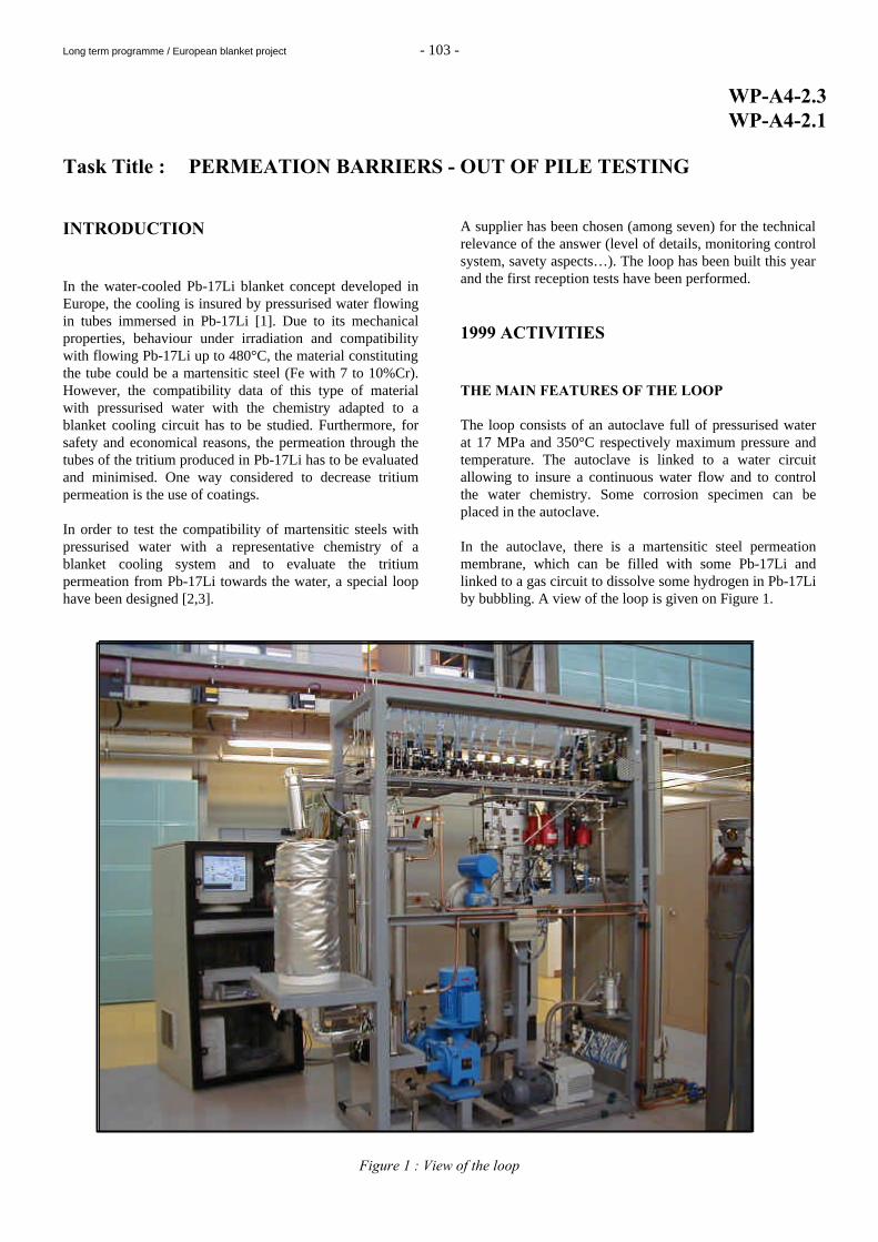
A supplier has been chosen (among seven) for the technical relevance of the answer (level of details, monitoring control system, savety aspects…). The loop has been built this year and the first reception tests have been performed. 1999 ACTIVITIES THE MAIN FEATURES OF THE LOOP The loop consists of an autoclave full of pressurised water at 17 MPa and 350°C respectively maximum pressure and temperature. The autoclave is linked to a water circuit allowing to insure a continuous water flow and to control the water chemistry. Some corrosion specimen can be placed in the autoclave. In the autoclave, there is a martensitic steel permeation membrane, which can be filled with some Pb-17Li and linked to a gas circuit to dissolve some hydrogen in Pb-17Li by bubbling. A view of the loop is given on Figure 1.
Figure 1 : View of the loop
Long term programme / European blanket project - 104 -
This loop allows to perform corrosion tests in water and hydrogen permeation measurements from Pb-17Li towards water. The autoclave The autoclave is made of 316L stainless steel and has a 5-litre inner volume, a 120 mm internal diameter, a 32 mm thickness and is 400 mm high. On the bottom of the autoclave are fixed the tubes for water inlet and outlet and a Pd/Ag membrane for measuring the hydrogen pressure in equilibrium with the dissolved hydrogen in the water. The autoclave is closed by a flange on which are fixed: a pressure gauge, a finger for a thermocouple allowing to measure the temperature inside the autoclave and the permeation chamber. The tightness is insured by a metallic seal. The autoclave heating is insured by heating resistances rolled round the external surface of the autoclave. The design temperature and pressure of the autoclave have been respectively 400°C and 20 MPa. The permeation chamber The permeation chamber is a cylinder fixed to the autoclave closing flange. It is made of a 9 Cr martensitic steel. It has been calculated to withstand a 25 MPa maximum external pressure at a 400°C maximum temperature. It is closed by a flange with a metallic seal. It can contain an 85 cm3 maximum Pb-17Li volume.
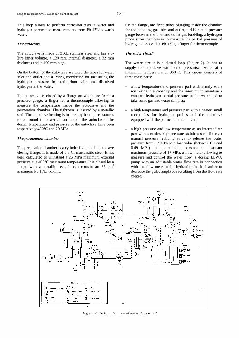
On the flange, are fixed tubes plunging inside the chamber for the bubbling gas inlet and outlet, a differential pressure gauge between the inlet and outlet gas bubbling, a hydrogen probe (iron membrane) to measure the partial pressure of hydrogen dissolved in Pb-17Li, a finger for thermocouple. The water circuit The water circuit is a closed loop (Figure 2). It has to supply the autoclave with some pressurised water at a maximum temperature of 350°C. This circuit consists of three main parts: - a low temperature and pressure part with mainly some
ion resins in a capacity and the reservoir to maintain a constant hydrogen partial pressure in the water and to take some gas and water samples;
- a high temperature and pressure part with a heater, small
receptacles for hydrogen probes and the autoclave equipped with the permeation membrane;
- a high pressure and low temperature as an intermediate
part with a cooler, high pressure stainless steel filters, a manual pressure reducing valve to release the water pressure from 17 MPa to a low value (between 0.1 and 0.49 MPa) and to maintain constant an upstream maximum pressure of 17 MPa, a flow meter allowing to measure and control the water flow, a dosing LEWA pump with an adjustable water flow rate in connection with the flow meter and a hydraulic shock absorber to decrease the pulse amplitude resulting from the flow rate control.
Figure 2 : Schematic view of the water circuit
Long term programme / European blanket project - 105 -
The gas and vacuum circuits The main function of the gas circuit is to insure a gas circulation in Pb-17Li and to allow to the gas flow to be periodically analysed. A schematic view is given on Figure 5. The gas circulation is insured by a SRTI compressor fitted with a by-pass with a regulation valve connected to a flow meter for the gas flow regulation; All the membranes (Pd/Ag and iron), the reservoir atmosphere and gas sampling systems are connected to the vacuum system and the chromatograph. The monitoring control system The control box contains an automaton, various indicators for pumps, temperatures…, a speed regulator for the gas compressor, temperature regulators and relays to manage security actions. The informatics system consists of a computer with the PANORAMA executive software. It allows together with the automaton to control the security systems, to release the security operations, to choose the parameters (temperatures, flow rates…) and the threshold values for security operations and to view the different parts of the loop. Gas analyser The gas analyser is a chromatograph allowing to separate the hydrogen isotopes by means of a cryogenic column. It is connected to the sampling devices of the gas circuit. THE FIRST QUALIFICATION TESTS Preliminary to perform the tests, it has been necessary to learn to use the monitoring control system. After that, qualification tests have allowed to check that: - all the loop (including the gas and water circuits and
the autoclave) is tight; - the water circuit can withstand, in its high temperature
and pressure part, 350°C and water under 17 MPa and, in its low pressure part, water under 0.49 MPa;
- the temperature differences along the autoclave at
330°C are less than 5°C; - water pump with the control system can provide a
water flow rate between 2 and 20 L h-1 with a 10% maximum fluctuations;
- the gas flow rate delivered by the compressor of the gas
circuit is between 3 and 15 NTPL h-1 with a 10% maximum fluctuations.
Some security procedures have been tested in particular it has been verified that the loop is stopped in case of a too large increase of pressure or temperature or if the water level in the storage tank is too low.
CONCLUSION In the frame of the water-cooled Pb-17Li liquid blanket development for fusion reactors, a new loop has been built in order to perform on one hand hydrogen permeation tests from Pb-17Li towards pressurised water and on the other hand corrosion tests in water environment. It consists of four main parts: an autoclave, a water circuit, a gas circuit and a monitoring control system. The autoclave calculated to work at 350°C and 17 MPa maximum respectively temperature and water pressure contains the permeation chamber and the corrosion coupons. It is connected to a water circuit allowing to maintain a water flow in the autoclave and control the water chemistry during operations. The permeation chamber contains static Pb-17Li in which hydrogen is dissolved by means of a gas bubbling provided by the gas circuit. The monitoring control system allows to run the loop to active stopping procedures in case of a malfunction. The loop is completely built and some first qualification tests have been performed in order to verify the performances of the loop and also the security procedures. REPORTS AND PUBLICATIONS T. Dufrenoy, A. Terlain, Tritium permeation from Pb-17Li towards water and corrosion loop CEA Report, RT SCECF 513 (December 1999) TASK LEADER A. TERLAIN CEREM/DECM/SCECF CEA Saclay 91191 Gif-sur-Yvette Cedex Tél. : 33 1 69 08 16 18 Fax : 33 1 69 08 15 86 E-mail : [email protected]
Long term programme / European blanket project - 106 -
WP-A4-3.1 Task Title : IN-PILE TESTS OF TRITIUM PERMEATION BARRIER AND
DOUBLE WALL TUBES INTRODUCTION In the framework of the WCLL Blanket development [1], some of the module components like the Double Wall Tubes (DWT) and the Tritium Permeation Barriers (TPB) are being developed and have to be qualified by in-pile tests. For that purpose, subtasks A4.3.2 and A4.3.3 are intended to define some in-pile test proposals respectively in BR2 (Mol) and HFR (Petten). These proposals have been analysed and oriented by CEA in the framework of subtask A4.3.1. 1999 ACTIVITIES EVALUATION OF THE SCK.CEN/MOL IN-PILE TEST PROPOSAL A purposely-built installation dedicated to accurate irradiation of DWT in BR2 - the MODELLI experiment – had been previously proposed by SCK.CEN/Mol. It corresponded to the most representative and comprehensive experiment envisaged on DWT (PbLi environment, TPB test,…), but it has led to a rather high construction cost. In the framework of 1999 subtask A4.3.3, SCK-CEN has been asked to propose low-cost alternatives for in-pile tests of Double Wall Tubes (DWT). Two low-cost proposals [2] have been defined by SCK.CEN. They consist essentially of experiments thought to best exploit the advantages of the BR2 reactor in Mol over the HFR in Petten which are big channel sizes and the possibility to use PWR type cooling water. The first experiment, at the minimum cost, consist in irradiating a DWT sample as a non-instrumented capsule. In this configuration, the DWT forms the central hole of the capsule, a thick tube forming the external wall. The central hole is cooled by a water flow at about [260-300]°C. The space between the outer wall and the DWT can be filled with low pressure inner gas or vacuum. The two tubes may be welded together in order to create longitudinal stress or specific bellows may be introduced to allow a differential thermal expansion. This first proposal does not include thermocouples and does not allow measurement of the temperature across the thickness of the DWT. This makes checking of the bonding very difficult. Tubes could however be extracted between two cycles for examination by eddy current sensor (detection of superficial cracks) or neutronography (detection of layers separation).
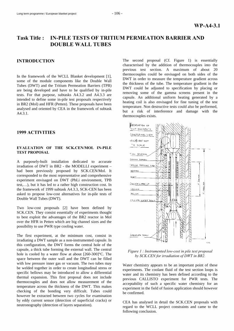
The second proposal (Cf. Figure 1) is essentially characterised by the addition of thermocouples into the previous test section. A maximum of about 20 thermocouples could be envisaged on both sides of the DWT in order to measure the temperature gradient across the thickness of the tube. The temperature gradient in the DWT could be adjusted to specification by placing or removing some of the gamma screens present in the capsule. An additional uniform heating generated by a heating coil is also envisaged for fine tuning of the test temperature. Non destructive tests could also be performed, but a risk of interference and damage with the thermocouples exists.
Figure 1 : Instrumented low-cost in pile test proposal by SCK.CEN for irradiation of DWT in BR2.
Water chemistry appears to be an important point of these experiments. The coolant fluid of the test section loops is water and its chemistry has been defined according to the previous CALLISTO experiment for PWR tests. The acceptability of such a specific water chemistry for an experiment in the field of fusion application should however be confirmed. CEA has analysed in detail the SCK.CEN proposals with regard to the WCLL project constraints and came to the following conclusion.
Long term programme / European blanket project - 107 -
It appears clearly, on one hand, that the initial MODELLI experiment remains the most suitable option which is able to answer to the needs and features most of the characteristics of a Test Blanket Module but it comes too early in the schedule of the project (uncertainties with ITER-RC, qualification of double-walled tubes and permeation barriers). Furthermore, the experiment seemed to be quite expensive so that it was attributed a low priority last year. On the other hand, the second set of experiments (1999 low-cost proposals) are too similar to the one present in HFR at this time. It would be possible to justify only if the specimen currently irradiated in HFR (EXOTIC-8) fails so that an improved technique must be tested. Nevertheless, should blanket testing in a Next Step machine be confirmed and once suitable TPB are qualified, the possibility of a MODELLI-like experiment will need to be re-examined. Anyway no additional irradiation tests could be envisaged before getting clear results from on-going in-pile and out-of-pile results. EVALUATION OF THE NRG/PETTEN PROPOSAL AND ONGOING IN-PILE TESTS In the framework of Subtask A4.3.2, NRG had been initially asked to make proposals for Tritium Permeation Barriers (TPB) and Double Wall Tubes (DWT) irradiation tests in HFR/Petten.
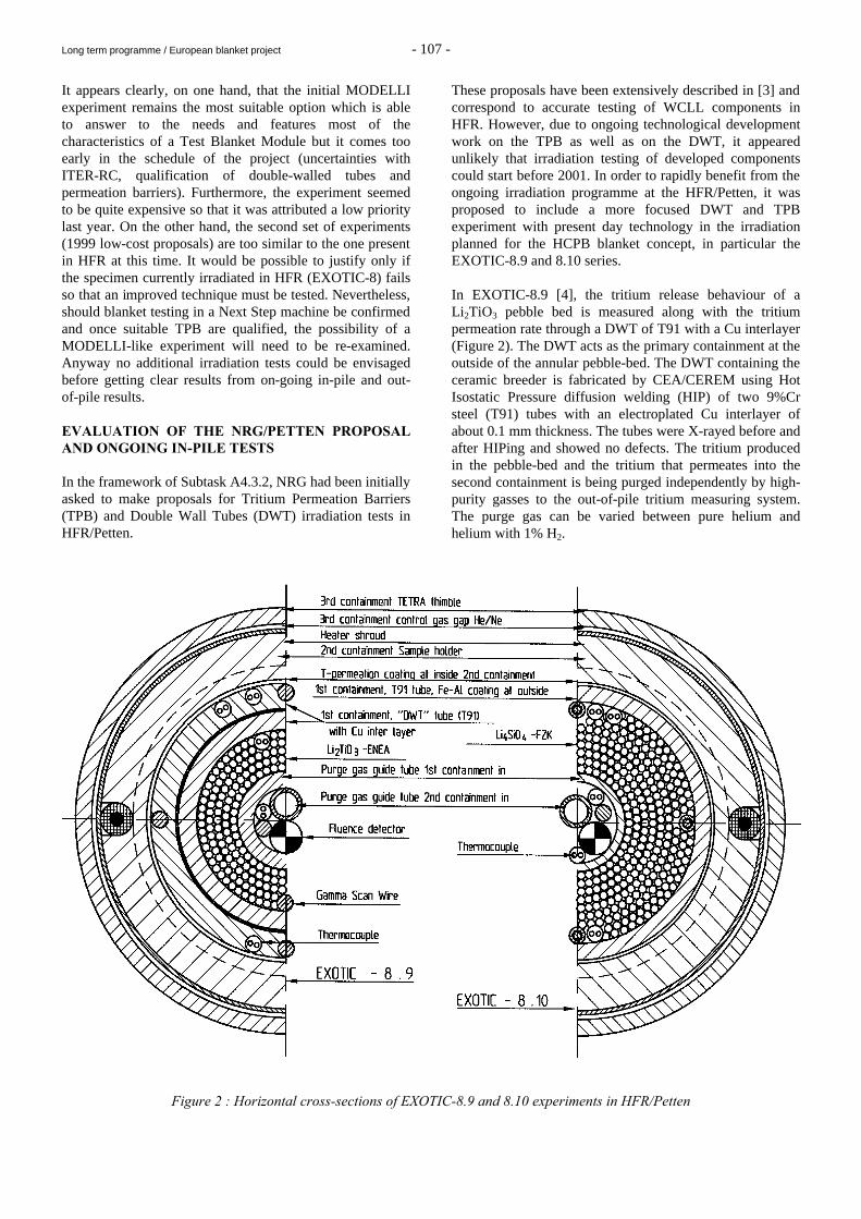
These proposals have been extensively described in [3] and correspond to accurate testing of WCLL components in HFR. However, due to ongoing technological development work on the TPB as well as on the DWT, it appeared unlikely that irradiation testing of developed components could start before 2001. In order to rapidly benefit from the ongoing irradiation programme at the HFR/Petten, it was proposed to include a more focused DWT and TPB experiment with present day technology in the irradiation planned for the HCPB blanket concept, in particular the EXOTIC-8.9 and 8.10 series. In EXOTIC-8.9 [4], the tritium release behaviour of a Li2TiO3 pebble bed is measured along with the tritium permeation rate through a DWT of T91 with a Cu interlayer (Figure 2). The DWT acts as the primary containment at the outside of the annular pebble-bed. The DWT containing the ceramic breeder is fabricated by CEA/CEREM using Hot Isostatic Pressure diffusion welding (HIP) of two 9%Cr steel (T91) tubes with an electroplated Cu interlayer of about 0.1 mm thickness. The tubes were X-rayed before and after HIPing and showed no defects. The tritium produced in the pebble-bed and the tritium that permeates into the second containment is being purged independently by high-purity gasses to the out-of-pile tritium measuring system. The purge gas can be varied between pure helium and helium with 1% H2.
Figure 2 : Horizontal cross-sections of EXOTIC-8.9 and 8.10 experiments in HFR/Petten
Long term programme / European blanket project - 108 -
The EXOTIC-8.10 [4] experiment is designed similar to EXOTIC-8.9, the breeder bed consisting of Li4SiO4 pebbles (FZK) instead of Li2TiO3 and being surrounded by a single-walled T91 tube coated on its outer side with a TPB. The TPB has been produced by pack-cementation process (FeAl-alloy) and CVD (Al2O3) at CEA/CEREM [5]. Tritium permeation rate through the Fe-Al/Al2O3-coated T91 tube is measured in gas-gas conditions, using the lithium-ceramics as the tritium source. The T release is studied with regard to the variation of temperatures and purge gas conditions [4]. In both cases, the capsules are instrumented with thermocouples and neutron detectors to monitor temperatures and to determine the neutron fluence after irradiation. Tritium concentration in the purge gas is measured by ionisation chambers. The T release results are presented and analysed in detailed in [4] for several gas purge conditions. Last results about the DIADEMO out-of-pile experiment [6] have indicated that NRG should wait for a clear interpretation of the first DIADEMO results before beginning PIE. It appeared indeed clear that additional efforts and analyses (numerical modelling, tests on SATIR,…) are necessary to explain the temperature results observed in DIADEMO. CONCLUSIONS In the framework of subtask A4.3.2 and A4.3.3 respectively, NRG/Petten and SCK.CEN/Mol have made proposals for in-pile testing of WCLL Test Blanket Module subcomponents such as Double Wall Tubes (DWT) and Tritium Permeation Barrier (TPB). These proposals have been analysed by CEA in the framework of subtask A4.3.1 in order to give an orientation and a decision on the future of the activity with regard to the project objectives and constraints. SCK-CEN Mol has been in charge during 1999 of a design subtask dealing with low-cost in-pile DWT tests in BR2. SCK.CEN has proposed two low-cost experiments which represent a significant effort with regard to cost compared to the initial MODELLI experiment. Two types of experiments have been proposed to best exploit the advantages of the BR2 reactor in Mol over the HFR in Petten which are big channel sizes and the possibility to use PWR type cooling water. The compatibility of this in-pile experiment with the PWR water chemistry still has to be demonstrated. CEA has analysed all the SCK.CEN proposal and concluded that the original MODELLI experiment featured most of the characteristics of a Test Blanket Module but came too early with regard to the uncertainties with ITER-RC and the qualification of double-walled tubes and permeation barriers. Furthermore, the experiment seemed to be quite expensive so that it was attributed a low priority last year.
The 1999 low-cost proposals appeared technically much less ambitious and corresponded basically to an irradiation test of double walled tubes. Such tests are very similar to the one currently underway at HFR and would not add any further knowledge at this stage, unless the HFR irradiation and ongoing DIADEMO out-of-pile tests should disqualify the current double-walled tube design. Concerning Subtask A4.3.2, NRG had initially proposed in-pile tests which could allow on-line measurement of T, but remain quite expensive. This year objective has been to take benefit from the ongoing EXOTIC-8.9/10 irradiation experiments to reduce the project costs. In that sense, a DWT and a T91 TPB coated with Fe-Al/Al2O3 have been tested respectively in the EXOTIC-8.9 and 8.10 experiments. Before engaging PIE, CEA and NRG have recommend an increased modelling effort on the analysis and interpretation of the out-of-pile results in DIADEMO. Further irradiation efforts could now be envisaged only after satisfactory level of components development, achieved out-of-pile and first in-pile tests analyses and less uncertainties regarding budget and cost aspects. REPORTS AND PUBLICATIONS [1] M. Fütterer et al., “Design Description Document
(DDD) for the European Water-cooled Pb-17Li Test Blanket Module”, CEA report SERMA/LCA/2125, December 1997.
[2] Ph. Benoit, “Irradiation of DWT segments –
Simplified irradiation device“, SCK.CEN technical note NT.57/F042030/06/PB, March 1999.
[3] J. G. van der Laan, R. Conrad, K. Bakker, “Irradiation
Testing of Double-Wall Tubes and Permeation Barriers in the HFR Petten“, NRG internal report 71177/99.22840/i, February 1999.
[4] R. Conrad et al., “In-Pile Tritium Permeation
Measurements on T91 Tubes with Double Walls or FeAl +Al2O3 Coating“, ICFRM-9, Colorado Springs, USA, October 1999.
[5] C. Chabrol et al., “Development of Fe-Al CVD
coatings as tritium permeation barrier“, Proceedings of the 20th SOFT, Marseille, 7-11 September 1998.
[6] Y. Poitevin, M; Fütterer, “Minutes of the 8th WCLL
Coordination Group meeting - March 5th 1999, CEA/Saclay“, CEA/SERMA, March 1999.
Y. Poitevin, M. Fütterer, « Support and analyses for WCLL in-pile tests of barriers and DWT », CEA internal report SERMA/LCA/RT/00-2763/A, March 2000.

Long term programme / European blanket project - 109 -
TASK LEADER Yves POITEVIN DRN/DMT/SERMA CEA Saclay 91191 Gif-sur-Yvette Cedex Tél. : 33 1 69 08 31 86 Fax : 33 1 69 08 99 35 E-mail : [email protected]
Long term programme / European blanket project - 110 -
WP-A5-1 Task Title : TRITIUM EXTRACTION FROM Pb-17Li USING GAS-LIQUID
CONTACTORS INTRODUCTION Within the framework of the development of a process to remove the tritium from a water cooled liquid Pb-17Li blanket, experiments on hydrogen extraction from Pb-17Li have been carried out between 1996 and 1998, in the Melodie loop, using a packed extractor [1-3]. These studies have shown that improved extraction performances are obtained with this type of contactor compared to the ones achieved with other previously tested technologies (bubbles column and plates column). From considerations on the mass transfer kinetics, based on these experimental results, it appeared that a key for the design of a suitable process is the knowledge and control of the liquid flow in the contactor. To reach that goal, it was proposed to observe, through a glass column, the hydraulic behaviour of mercury at room temperature on the structured packing, as a simulation of the Pb-17Li flow. Then, the building of the Mercury loop, a new facility dedicated to that study, was decided for 1999. 1999 ACTIVITIES ORIGIN OF THE MERCURY LOOP The increase of the performances observed with the packing technology involves a split up of the Pb-17Li flow resulting from the limitation of mass transfer in the liquid phase. A key issue for the design of the tritium removal process is the knowledge and control of the liquid flow in the contactor. As the liquid flow observation was not possible in the Melodie loop which operated with Pb-17Li at temperatures close to 673 K, the hydraulic conditions in which these improved performances were obtained are not known. Two different types of Pb-17Li flow through the packing can actually be assumed: - a liquid film flow if the Pb-17Li wetting was significant, - a flow of dispersed streams and/or droplets if the
wetting was weak. The size extrapolations of the contactor require: - to determine which was the actual type of flow. - to obtain more information about the radial spreading of
the liquid alloy flow.
Moreover, for larger liquid flow rates, it will be necessary: - to determine the best technology adapted to this flow.
For instance, in the case of a flow of liquid droplets, the Mellapak structured packing should not be the most appropriate way to generate high flux of small droplets;
- to reliably control the occurrence of one type of flow or
another as a function of the dimensions of the system; - to determine if intermediate liquid distributors have to
be placed along the column to avoid a liquid preferential flow close to the extractor wall and design them.
Therefore, it has been decided to build a new device using liquid mercury at room temperature in order to visualise, through a glass column, the liquid flow on different packing technologies such as the Mellapak packing. The choice of mercury at room temperature instead of Pb-17Li at 673K, has been initiated by the slight differences between their superficial tensions (γ Hg, 293K = 0.48 and γ Pb-17Li, 673K = 0.42 J m-2) and their viscosities (µ Hg, 293K = 1.55 10-3 and µ Pb-17Li, 673K = 1.50 10-3 Pa s) and by the relative closeness of their densities (ρ Hg, 293K = 13540 and ρ Pb-17Li, 673K = 9317 kg m-3). These properties appear to be crucial since the behaviour of Pb-17Li on the packing cylinders results from: - its capacity to wet the surface of the packing material
which depends on γ, its superficial tension, - the hydraulic parameters affecting its gravitational flow:
viscosity and density. Moreover, a study on the comparative wetting of metallic materials by Pb-17Li and Hg is under progress. DESCRIPTION OF THE MERCURY LOOP The study of the mercury flow in a column has required the construction of an experimental apparatus placed in a ventilated cell, the mercury loop, with well defined liquid and gas circuits to meet the following requirements: - technical availability to make a video of the liquid flow
in the contactor, - technical flexibility since the parameters to be studied
are the liquid flow rate, the type and the size of the extractor technology,
- safety since vapours of mercury are volatile and highly
toxic.
Long term programme / European blanket project - 111 -
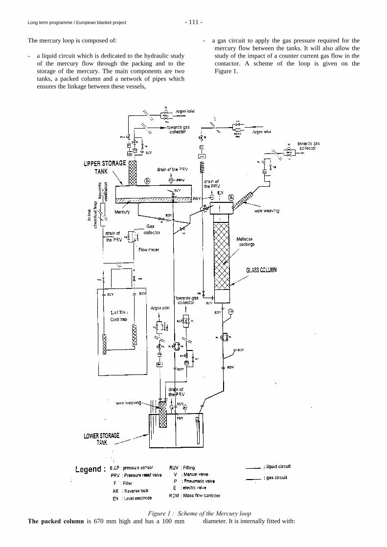
The mercury loop is composed of: - a liquid circuit which is dedicated to the hydraulic study
of the mercury flow through the packing and to the storage of the mercury. The main components are two tanks, a packed column and a network of pipes which ensures the linkage between these vessels,
- a gas circuit to apply the gas pressure required for the mercury flow between the tanks. It will also allow the study of the impact of a counter current gas flow in the contactor. A scheme of the loop is given on the Figure 1.
Figure 1 : Scheme of the Mercury loop The packed column is 670 mm high and has a 100 mm diameter. It is internally fitted with:
Long term programme / European blanket project - 112 -
- two Mellapack 750Y cylinders made of AISI 410S, each
of them being a 200mm high; - a liquid dristributor to insure the initial spreading of the
liquid; - a level electrode; - a gas injector at the bottom of the column to produce a
counter current gas flow. The upper and lower storage tanks have a large volume to reduce the pressure drops during operation and then improve the stability of the gas control-command. The liquid circuit is made of pipes with a sufficiently large diameter to avoid excessive mechanical stresses in the structures. This circuit is fitted with pneumatic valves which are, for most of them bypassed with manual valves for safety reasons.
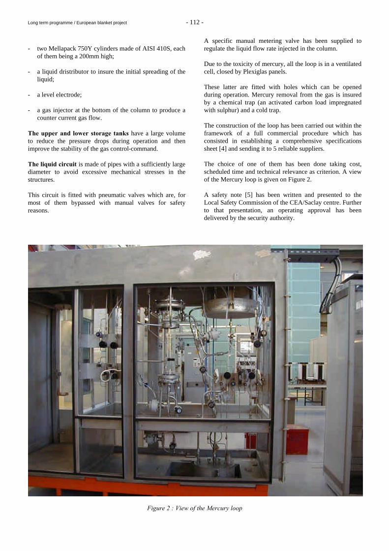
A specific manual metering valve has been supplied to regulate the liquid flow rate injected in the column. Due to the toxicity of mercury, all the loop is in a ventilated cell, closed by Plexiglas panels. These latter are fitted with holes which can be opened during operation. Mercury removal from the gas is insured by a chemical trap (an activated carbon load impregnated with sulphur) and a cold trap. The construction of the loop has been carried out within the framework of a full commercial procedure which has consisted in establishing a comprehensive specifications sheet [4] and sending it to 5 reliable suppliers. The choice of one of them has been done taking cost, scheduled time and technical relevance as criterion. A view of the Mercury loop is given on Figure 2. A safety note [5] has been written and presented to the Local Safety Commission of the CEA/Saclay centre. Further to that presentation, an operating approval has been delivered by the security authority.
Figure 2 : View of the Mercury loop
Long term programme / European blanket project - 113 -
CONCLUSION This year has been devoted to the design and the construction of a new experimental facility, the Mercury loop. Within the framework of the studies carried out for the development of a process allowing to remove tritium from Pb-17Li, this facility is dedicated to the observation of the mercury flow at room temperature as a simulation of the Pb-17Li flow at 673 K inside a tritium extractor. The Mercury loop should be a convenient tool to perform, at low cost, hydraulic tests with mercury on various technologies of gas-liquid contactors, such as packings, in order to make a first selection before carrying on expensive and complex tests with Pb-17Li. In the present state of our knowledge, these studies are necessary since size extrapolations of the structured packing, which was successfully tested in 1998 on the Melodie loop would be highly unreliable with regard to the lack of data about the type of liquid flow taking place on it (liquid film flow or flow of streams and droplets). At present, the Mercury loop facility has been supplied and tightness tests have been performed. The approval for the starting of the loop has been delivered by the safety authority of the CEA/Saclay centre. However, the first tests with mercury, initially scheduled for this year, have not be performed because the experimental program of the mercury loop, in the frame of the Water Cooled Liquid Blanket, has been stopped for next year while any support has been provided for the later dismantling of the facility (mercury decontamination). REPORTS AND PUBLICATIONS [1] N. Alpy, T. Dufrenoy, A. Terlain, Hydrogen extraction
from Pb-17Li: tests with a packed column, Fusion Eng. and Design, 42 (1998) 569-592
[2] N. Alpy, A. Terlain, M. Perrot, T. Dufrenoy,
Hydrogen extraction from Pb-17Li: 1997 results on the packed column running and 1998 views, RT SCECF/446 (Décembre 1997)
[3] N. Alpy, A. Terlain, V. Lorentz, Hydrogen extraction
from Pb-17Li: 1998 results with a 800 mm high packed column, RT SCECF/485 (Décembre 1998)
[4] N. Alpy, A. Terlain, V. Lorentz, Réalisation d’une
boucle expérimentale en boîte à gants permettant l’étude d’un écoulement contre-courant gaz-mercure sur un garnissage, LECNA/99-067 (Avril 1999)
[5] N. Alpy, A. Terlain, V. Lorentz, M. Perrot, Dossier de
sécurité de la boucle Mercure, NT SCECF/006 (Septembre 1999)
- N. Alpy, A. Terlain, V. Lorentz, M. Perrot HYDRAULIC STUDY OF THE Pb-17Li FLOW IN
THE TRITIUM EXTRACTOR: design and construction of an experimental facility, the MERCURY loop
CEA Report, RT SCECF 508 (December 1999) - N. Alpy, A. Terlain, Hydrogen extraction from Pb-17Li: results with a 800
mm high packed column, Proceedings of ISFNT-5, Rome, 20-24 September
1999, to be published. TASK LEADER A. TERLAIN CEREM/DECM/SCECF CEA Saclay 91191 Gif-sur-Yvette Cedex Tél. : 33 1 69 08 16 18 Fax : 33 1 69 08 15 86 E-mail : [email protected]
Long term programme / European blanket project - 114 -
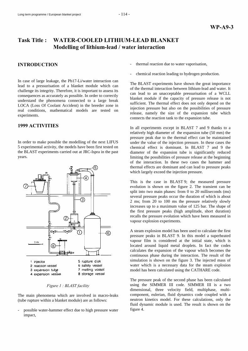
WP-A9-3 Task Title : WATER-COOLED LITHIUM-LEAD BLANKET Modelling of lithium-lead / water interaction INTRODUCTION In case of large leakage, the Pb17-Li/water interaction can lead to a pressurisation of a blanket module which can challenge its integrity. Therefore, it is important to assess its consequences as accurately as possible. In order to correctly understand the phenomena connected to a large break LOCA (Loss Of Coolant Accident) in the breeder zone in real conditions, mathematical models are tested on experiments. 1999 ACTIVITIES In order to make possible the modelling of the next LIFUS 5 experimental activity, the models have been first tested on the BLAST experiments carried out at JRC-Ispra in the past years.
Figure 1 : BLAST facility
The main phenomena which are involved in macro-leaks (tube rupture within a blanket module) are as follows: - possible water-hammer effect due to high pressure water
impact,
- thermal reaction due to water vaporisation, - chemical reaction leading to hydrogen production. The BLAST experiments have shown the great importance of the thermal interaction between lithium-lead and water. It can lead to an unacceptable pressurisation of a WCLL blanket module if the capacity of pressure release is not sufficient. The thermal effect does not only depend on the injection pressure but also on the possibilities of pressure release, namely the size of the expansion tube which connects the reaction tank to the expansion tube. In all experiments except in BLAST 7 and 9 thanks to a relatively high diameter of the expansion tube (50 mm) the pressure peak due to the thermal effect can be maintained under the value of the injection pressure. In these cases the chemical effect is dominant. In BLAST 7 and 9 the diameter of the expansion tube is significantly reduced limiting the possibilities of pressure release at the beginning of the interaction. In these two cases the hammer and thermal effects are dominant and can lead to pressure peaks which largely exceed the injection pressure. This is the case in BLAST 9; the measured pressure evolution is shown on the figure 2. The transient can be split into two main phases: from 0 to 20 milliseconds (ms) several pressure peaks occur the duration of which is about 2 ms; from 20 to 100 ms the pressure relatively slowly increases up to a maximum value of 125 bar. The shape of the first pressure peaks (high amplitude, short duration) recalls the pressure evolution which have been measured in vapour explosion experiments. A steam explosion model has been used to calculate the first pressure peaks in BLAST 9. In this model a superheated vapour film is considered at the initial state, which is located around liquid metal droplets. In fact the codes calculates the expansion of the vapour which becomes the continuous phase during the interaction. The result of the simulation is shown on the figure 3. The injected mass of water which is a necessary data for the steam explosion model has been calculated using the CATHARE code. The pressure peak of the second phase has been calculated using the SIMMER III code. SIMMER III is a two dimensional, three velocity field, multiphase, multi-component, eulerian, fluid dynamics code coupled with a neutron kinetics model. For these calculations, only the fluid dynamic module is used. The result is shown on the figure 4.
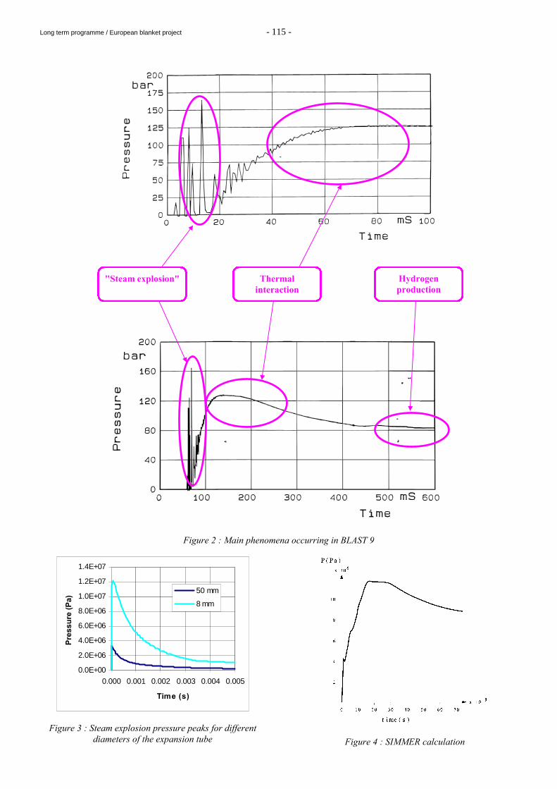
Long term programme / European blanket project - 115 -
Figure 2 : Main phenomena occurring in BLAST 9
0.0E+00
2.0E+06
4.0E+06
6.0E+06
8.0E+06
1.0E+07
1.2E+07
1.4E+07
0.000 0.001 0.002 0.003 0.004 0.005
Time (s)
Pre
ssu
re (
Pa)
50 mm
8 mm
Figure 3 : Steam explosion pressure peaks for different diameters of the expansion tube
Figure 4 : SIMMER calculation
"Steam explosion" Thermal interaction
Hydrogen production
Long term programme / European blanket project - 116 -
The results of the calculations can be compared with the experimental results shown on the figure 2. CONCLUSIONS The BLAST experiments show the great importance of the thermal interaction between lithium-lead and water. It can lead to an unacceptable pressurisation of a WCLL blanket module if the capacity of pressure release is not sufficient. The main phenomena which are likely to occur during the interaction are identified. Some models are available which allow us to provide satisfactory simulations of these phenomena; we are notably able to quantify the influence of the size of the expansion tube as well as the operative conditions and geometry on the interaction evolution. This is important to make possible a reliable scaling-up to the real geometry and operative conditions. REPORTS AND PUBLICATIONS [1] Kottowski et al., Studies with respect to the estimation
of liquid metal blanket safety, Fusion engineering and design, 445-448, 1991
[2] Savatteri, Gemelli, Lithium-lead water interaction.
Large break experiments, Fusion engineering and design, 343-349, 1991
[3] Kondo et al., Status and achievment of assessment
programme for SIMMER III a multiphase multicomponent code for LMFBR safety analysis, NURETH 8 Kyoto Japan 1997
[4] M.D. Oh, M.L. Corradini, A non equilibrium model
for large scale vapour explosions, 3rd International conference on Reactor Thermal-hydraulics, Newport Rhode Island, 1985
[5] F. Barré, D. Bestion, Validation of the CATHARE
system code for nuclear reactor thermal hydraulics, ASME & JSME Fluid Engineering Conference South Carolina USA, 1995
[6] J.R. Jevais, Code CIGALON - Comparaison et
validation des versions V1 et V2 sur la base des essais KROTOS en alumine, Report IPSN/DRS/SEMAR 97/70
P. Sardain, Modelling of the lithium-lead/water interaction within a blanket module, CEA report DER/SERSI/LECC 99/4034 P. Sardain, Contribution to the definition of the LIFUS 5 tests, CEA report DER/SERSI/LECC 99/4066 P. Sardain, I. Ricapito, G. Benamati, G. Marbach, Modelling of the Pb-17Li/water interaction within a blanket module, ISFNT5, Rome, Italy, September 1999 TASK LEADER Pierre SARDAIN DRN/DER/SERSI/LECC CEA Cadarache 13108 St Paul Lez Durance Cedex Tél. : 33 4 42 25 37 59 Fax : 33 4 42 25 71 87 E-mail : [email protected]
Long term programme / European blanket project - 117 -
WP-A10-2 Task Title : EXPERIMENTAL DEMONSTRATION OF MHD PHENOMENA Turbulence in MHD flow shear layers INTRODUCTION The objective is to give a contribution to the understanding of the Pb-17Li flow behaviour in the WCLL blanket and in particular to assess the presence of two-dimensional turbulence in MHD flow shear layers and to characterise them under representative magnetic field. Relevant parameters and scaling laws have to be obtained in order to evaluate the impact of MHD effects on Pb-17Li velocity and temperature distribution and consequently on the T-permeation towards the water coolant in WCLL blankets. 1999 ACTIVITIES Theoretical, numerical and experimental results were obtained since 1996 within the framework of the studies on the turbulence of MHD flows in the water-cooled lithium lead blankets of fusion reactors. The activity this year has been marked by the improvement of the MATUR cell (MATUR-6) and by a new collection of experimental results obtained under intense magnetic fields which can reach 6 Tesla. MATUR-6 EXPERIMENTAL DEVICE The configuration of the experimental device MATUR-6 is identical to that of the preceding versions. The circular cell with a radius of 11 cm contains a mercury layer with a thickness set at 1 cm, in which the electric current is injected by electrodes located in a circle of 9.3 mm in radius and closes by the external cylindrical wall maintained at constant temperature, thus starting a rotational movement of the external fluid cylinder. A central heating plot allows the injection of 10 watts in power in order to observe the turbulent transport of a scalar such as the heat through the shear layer. Compared to the former versions, a new arrangement of improved potential probes was set up : 140 probes in order to measure the radial and the orthoradial components of the velocity, the temperature and the vorticity. The MATUR-6 cell has been placed in a LCMI coil (Laboratoire des Champs Magnetiques Intenses) in Grenoble thus making the magnetic field continuously vary between 0 and 6 Teslas, and consequently allowing conditions representative of fusion reactor blankets to be reached.
The electrical current, characterizing the maximum speed of the fluid cylinder, reached an intensity of 100A, in other terms rates of roughly 1m/s. EXPERIMENTAL RESULTS The experimental campain of measurements under intense magnetic field provided a huge data bank for which the processing nd the analyses are rather complicated. The interpretation of the recorded data is in progress. Nevertheless, we are able to present hereafter the major results obtained with the MATUR-6 cell under intense magnetic field. The main objectives of the experiments carried out under intense magnetic field are : - the study of the influence of the turbulent shear flow
properties that means : * the influence of the magnetic field and of the
injected current on the mean flow and the energy transfer between the different scales of turbulence,
* the behavior of the free turbulent shear layer, * the study of the free shear layer instability, * the study of the dynamic of the coherent structures,
- the analysis of the transient flows (sudden acceleration and slowdown),
- the study of the heat transfer properties between the
center and the external wall of the cell. PROPERTIES OF THE TURBULENT FLOW The mean flow The most significant parameter for the characterization of the mean flow (similar to the flow rate in a duct) is the global kinetic momentum which includes information on position and velocity. The figure 1 shows the distribution of the global kinetic momentum as a function of the injected current calculated for different values of the magnetic field. It is to be noticed that, for magnetic field values less than 1 Tesla, the profiles of kinetic momentum are saturated for high current intensity. This can be explained by the occurrence of a meridian flow (Eckman pumping) typical of rotating flow and which disappears as soon as the magnetic field exceeds 1 Tesla.
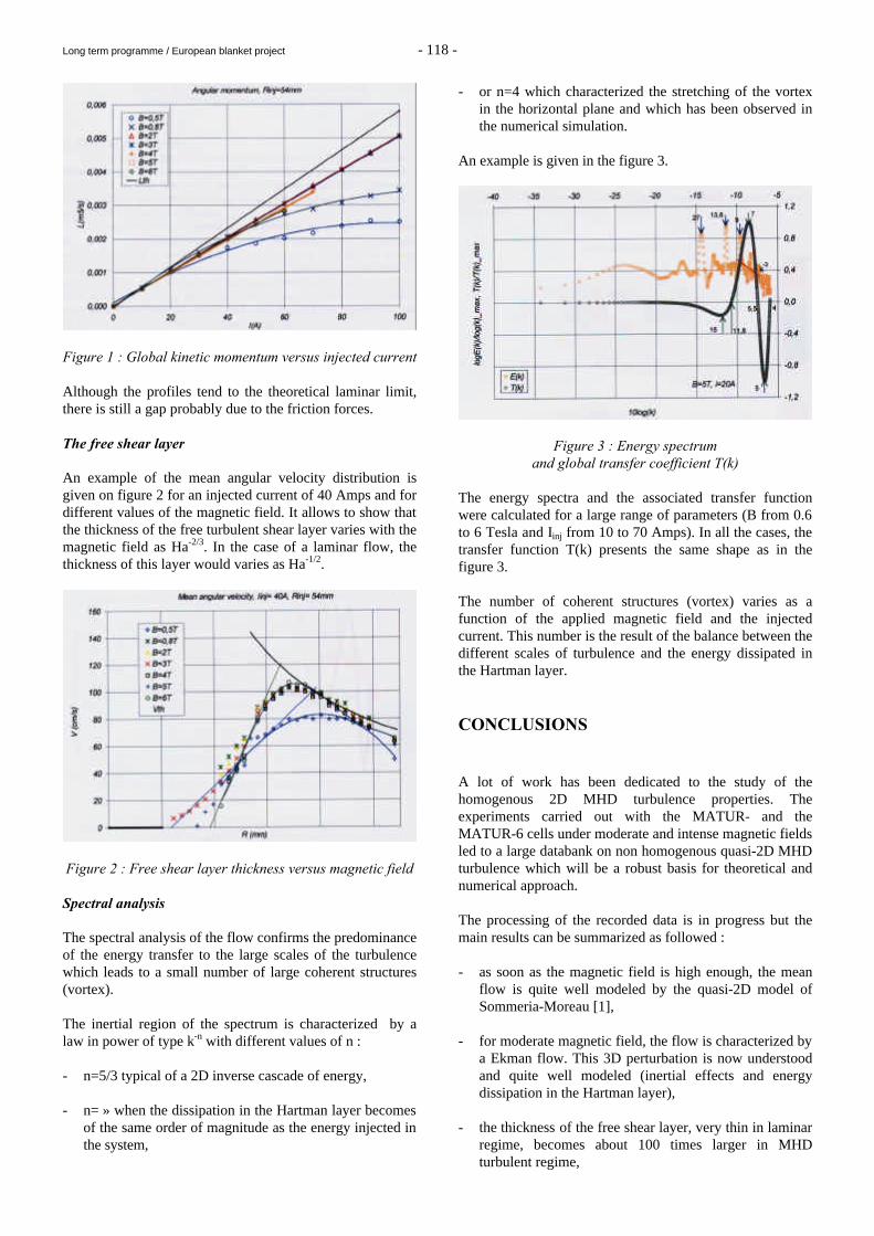
Long term programme / European blanket project - 118 -
Figure 1 : Global kinetic momentum versus injected current Although the profiles tend to the theoretical laminar limit, there is still a gap probably due to the friction forces. The free shear layer An example of the mean angular velocity distribution is given on figure 2 for an injected current of 40 Amps and for different values of the magnetic field. It allows to show that the thickness of the free turbulent shear layer varies with the magnetic field as Ha-2/3. In the case of a laminar flow, the thickness of this layer would varies as Ha-1/2.
Figure 2 : Free shear layer thickness versus magnetic field Spectral analysis The spectral analysis of the flow confirms the predominance of the energy transfer to the large scales of the turbulence which leads to a small number of large coherent structures (vortex). The inertial region of the spectrum is characterized by a law in power of type k-n with different values of n : - n=5/3 typical of a 2D inverse cascade of energy, - n= » when the dissipation in the Hartman layer becomes
of the same order of magnitude as the energy injected in the system,
- or n=4 which characterized the stretching of the vortex in the horizontal plane and which has been observed in the numerical simulation.
An example is given in the figure 3.
Figure 3 : Energy spectrum and global transfer coefficient T(k)
The energy spectra and the associated transfer function were calculated for a large range of parameters (B from 0.6 to 6 Tesla and Iinj from 10 to 70 Amps). In all the cases, the transfer function T(k) presents the same shape as in the figure 3. The number of coherent structures (vortex) varies as a function of the applied magnetic field and the injected current. This number is the result of the balance between the different scales of turbulence and the energy dissipated in the Hartman layer. CONCLUSIONS A lot of work has been dedicated to the study of the homogenous 2D MHD turbulence properties. The experiments carried out with the MATUR- and the MATUR-6 cells under moderate and intense magnetic fields led to a large databank on non homogenous quasi-2D MHD turbulence which will be a robust basis for theoretical and numerical approach. The processing of the recorded data is in progress but the main results can be summarized as followed : - as soon as the magnetic field is high enough, the mean
flow is quite well modeled by the quasi-2D model of Sommeria-Moreau [1],
- for moderate magnetic field, the flow is characterized by
a Ekman flow. This 3D perturbation is now understood and quite well modeled (inertial effects and energy dissipation in the Hartman layer),
- the thickness of the free shear layer, very thin in laminar
regime, becomes about 100 times larger in MHD turbulent regime,
Long term programme / European blanket project - 119 -
- this turbulence is characterized by a small number of large structures and by an inertial zone with a spectrum with a law in power of type E≈k-n with different values of n. This particular behavior underlines the requirement of adapted models in order to calculate this type of flow.
The processing of recorded data will go on in order to characterize the temperature field and the heat transfer. The convergence of the theoretical , numerical and experimental studies is now clearly established. The theory allowed the improvement in accuracy of the model-equation [1] with a view to extending its validity to high speed regimes and the numerical model is satisfactory at moderate speeds and will be applied to more representative flows of fusion reactor blankets. REPORT AND PUBLICATION [1] "Why, when and how MHD turbulence becomes two-
dimensional" - J. Somméria, R.Moreau, J. Fluid Mech.(1982), vol. 118 pp 507-518
TASK LEADER Guy LAFFONT DRN/DER/STPI/LCFI CEA Cadarache 13108 St Paul Lez Durance Cedex Tél. : 33 4 42 25 73 14 Fax : 33 4 42 25 77 88 E-mail : [email protected] This task is performed in close collaboration with the MADYLAM laboratory Contact : R. MOREAU EPM - MADYLAM UPR CNRS A 9033 ENSHMG BP95 38402 St
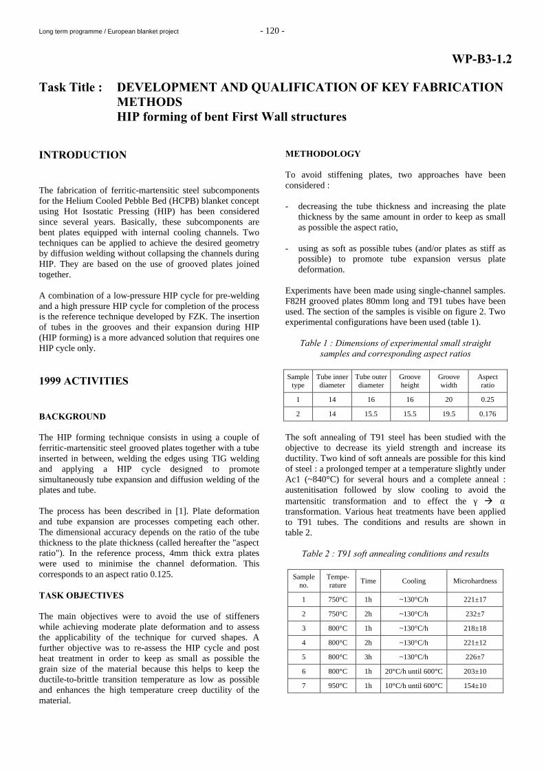
Long term programme / European blanket project - 120 -
WP-B3-1.2 Task Title : DEVELOPMENT AND QUALIFICATION OF KEY FABRICATION
METHODS HIP forming of bent First Wall structures INTRODUCTION The fabrication of ferritic-martensitic steel subcomponents for the Helium Cooled Pebble Bed (HCPB) blanket concept using Hot Isostatic Pressing (HIP) has been considered since several years. Basically, these subcomponents are bent plates equipped with internal cooling channels. Two techniques can be applied to achieve the desired geometry by diffusion welding without collapsing the channels during HIP. They are based on the use of grooved plates joined together. A combination of a low-pressure HIP cycle for pre-welding and a high pressure HIP cycle for completion of the process is the reference technique developed by FZK. The insertion of tubes in the grooves and their expansion during HIP (HIP forming) is a more advanced solution that requires one HIP cycle only. 1999 ACTIVITIES BACKGROUND The HIP forming technique consists in using a couple of ferritic-martensitic steel grooved plates together with a tube inserted in between, welding the edges using TIG welding and applying a HIP cycle designed to promote simultaneously tube expansion and diffusion welding of the plates and tube. The process has been described in [1]. Plate deformation and tube expansion are processes competing each other. The dimensional accuracy depends on the ratio of the tube thickness to the plate thickness (called hereafter the "aspect ratio"). In the reference process, 4mm thick extra plates were used to minimise the channel deformation. This corresponds to an aspect ratio 0.125. TASK OBJECTIVES The main objectives were to avoid the use of stiffeners while achieving moderate plate deformation and to assess the applicability of the technique for curved shapes. A further objective was to re-assess the HIP cycle and post heat treatment in order to keep as small as possible the grain size of the material because this helps to keep the ductile-to-brittle transition temperature as low as possible and enhances the high temperature creep ductility of the material.
METHODOLOGY To avoid stiffening plates, two approaches have been considered : - decreasing the tube thickness and increasing the plate
thickness by the same amount in order to keep as small as possible the aspect ratio,
- using as soft as possible tubes (and/or plates as stiff as
possible) to promote tube expansion versus plate deformation.
Experiments have been made using single-channel samples. F82H grooved plates 80mm long and T91 tubes have been used. The section of the samples is visible on figure 2. Two experimental configurations have been used (table 1).
Table 1 : Dimensions of experimental small straight samples and corresponding aspect ratios
Sample
type Tube inner diameter
Tube outer diameter
Groove height
Groove width
Aspect ratio
1 14 16 16 20 0.25
2 14 15.5 15.5 19.5 0.176
The soft annealing of T91 steel has been studied with the objective to decrease its yield strength and increase its ductility. Two kind of soft anneals are possible for this kind of steel : a prolonged temper at a temperature slightly under Ac1 (~840°C) for several hours and a complete anneal : austenitisation followed by slow cooling to avoid the martensitic transformation and to effect the γ à α transformation. Various heat treatments have been applied to T91 tubes. The conditions and results are shown in table 2.
Table 2 : T91 soft annealing conditions and results
Sample no.
Tempe-rature
Time Cooling Microhardness
1 750°C 1h ~130°C/h 221±17
2 750°C 2h ~130°C/h 232±7
3 800°C 1h ~130°C/h 218±18
4 800°C 2h ~130°C/h 221±12
5 800°C 3h ~130°C/h 226±7
6 800°C 1h 20°C/h until 600°C 203±10
7 950°C 1h 10°C/h until 600°C 154±10
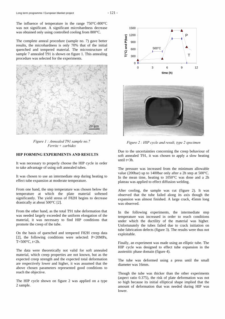
Long term programme / European blanket project - 121 -
The influence of temperature in the range 750°C-800°C was not significant. A significant microhardness decrease was obtained only using controlled cooling from 800°C. The complete anneal procedure (sample no. 7) gave better results, the microhardness is only 70% that of the initial quenched and tempered material. The microstructure of sample 7 annealed T91 is shown on figure 1. This annealing procedure was selected for the experiments.
Figure 1 : Annealed T91 sample no.7 Ferrite + carbides
HIP FORMING EXPERIMENTS AND RESULTS It was necessary to properly choose the HIP cycle in order to take advantage of using soft annealed tubes. It was chosen to use an intermediate step during heating to effect tube expansion at moderate temperature. From one hand, the step temperature was chosen below the temperature at which the plate material softened significantly. The yield stress of F82H begins to decrease drastically at about 500°C [2]. From the other hand, as the total T91 tube deformation that was needed largely exceeded the uniform elongation of the material, it was necessary to find HIP conditions that promote the creep of the tube. On the basis of quenched and tempered F82H creep data [2], the following conditions were selected: P=20MPa, T=500°C, t=2h. The data were theoretically not valid for soft annealed material, which creep properties are not known, but as the expected creep strength and the expected total deformation are respectively lower and higher, it was assumed that the above chosen parameters represented good conditions to reach the objective. The HIP cycle shown on figure 2 was applied on a type 2 sample.
0
300
600
900
1200
1500
0 3 6 9 12
time (h)
T(°
C)
and
P(b
ar) P
T
500°C
Figure 2 : HIP cycle and result, type 2 specimen Due to the uncertainties concerning the creep behaviour of soft annealed T91, it was chosen to apply a slow heating until t=3h. The pressure was increased from the minimum allowable value (200bar) up to 1400bar only after a 2h step at 500°C. In the mean time, heating to 1050°C was done and a 2h plateau was applied to effect diffusion welding. After cooling, the sample was cut (figure 2). It was observed that the tube failed along its axis though the expansion was almost finished. A large crack, 45mm long was observed. In the following experiments, the intermediate step temperature was increased in order to reach conditions under which the ductility of the material was higher. Unfortunately the tubes failed due to crack initiation on tube fabrication defects (figure 3). The results were thus not exploitable. Finally, an experiment was made using an elliptic tube. The HIP cycle was designed to effect tube expansion in the austenitic phase domain (figure 4). The tube was deformed using a press until the small diameter was 16mm. Though the tube was thicker than the other experiments (aspect ratio 0.375), the risk of plate deformation was not so high because its initial elliptical shape implied that the amount of deformation that was needed during HIP was lower.
20 µm
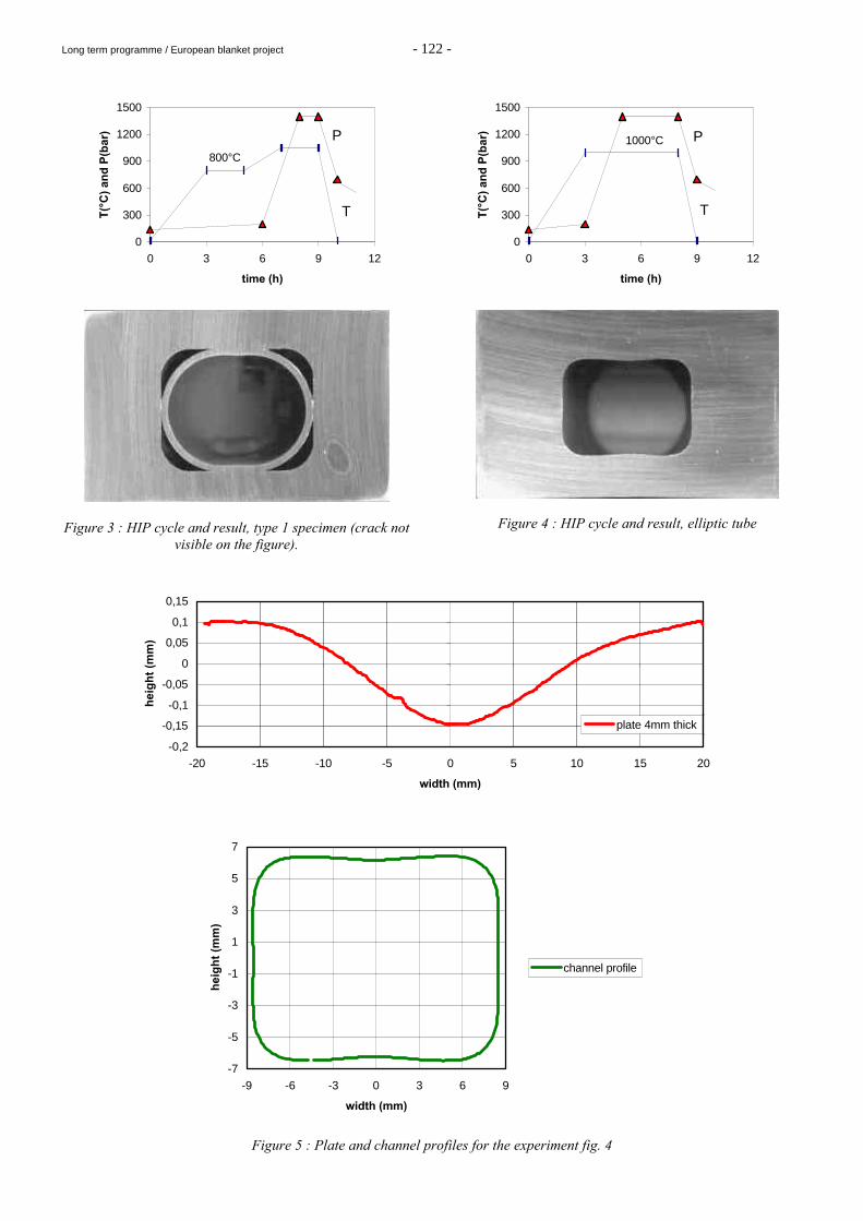
Long term programme / European blanket project - 122 -
0
300
600
900
1200
1500
0 3 6 9 12
time (h)
T(°
C)
and
P(b
ar) P
T
800°C
Figure 3 : HIP cycle and result, type 1 specimen (crack not
visible on the figure).
0
300
600
900
1200
1500
0 3 6 9 12
time (h)
T(°
C)
and
P(b
ar) P
T
1000°C
Figure 4 : HIP cycle and result, elliptic tube
-0,2
-0,15
-0,1
-0,05
0
0,05
0,1
0,15
-20 -15 -10 -5 0 5 10 15 20
width (mm)
hei
gh
t (m
m)
plate 4mm thick
-7
-5
-3
-1
1
3
5
7
-9 -6 -3 0 3 6 9
width (mm)
hei
gh
t (m
m)
channel profile
Figure 5 : Plate and channel profiles for the experiment fig. 4
Long term programme / European blanket project - 123 -
The tube did not fail. Its expansion was complete and no residual porosity could be detected at the groove/tube interface. Furthermore, the plate deformation was comparable to that obtained in the reference process despite no stiffening plates were used (figure 5). MOCK-UP FABRICATION It was planned to manufacture a curved mock to assess the applicability of the technique for curved shapes. It was not fabricated due to tubes unavailability. However, the plates were prepared. Grooves were machined and carbon steel bars were then used to fill grooves. Plates and bars were welded together and bent at room temperature. CONCLUSION To get minimum plate deformation without using stiffeners, two techniques were tried. First, soft annealing conditions for T91 were determined in order to make experiments with soft tubes. Second, the aspect ratio was decreased as much as possible. The experiments were unsuccessful mainly because of the poor tube quality. Besides this supplying problem, it remains that the total deformation needed for the expansion of the tubes is very high and the chance to find suitable HIP parameters to get tube expansion at moderate temperature, without failure, is tiny. It would require the determination of soft annealed ferritic-martensitic steel creep properties to optimise the pressure and temperature cycle. On the opposite, a very encouraging result was obtained using an elliptical tube despite a high aspect ratio. The deformation of the plates is moderate. The curved mock up could not be fabricated due to tubes unavailability.
REPORTS AND PUBLICATIONS [1] E. Rigal “Feasibility of first wall manufacturing by
hot isostatic pressing, HCPB concept, task WP B312”, CEA report Note technique DEM 71/97, 09 dec. 1997.
[2] L. Schäfer, M. Schirra, R. Lindau, "Mechanical
properties of the martensitic chromium steel F82H mod., heat 9741", proceedings of the 19th Symposium on Fusion Technology, Lisbon, Portugal, 16-20 September 1996, volume 2, pp1363-1366, Ed. C. Varandas and F. Serra, North Holland.
[3] E. Rigal “Development and qualification of key
fabrication methods : HIP forming of bent FW structures, task WP B312”, CEA report Note technique DEM 90/99, 16 dec. 1999
[4] E. Rigal, G. Le Marois, T. Lechler, G. Reimann, K.
Schleisiek, L. Shäfer, P. Weimar “Development of FM steels diffusion bonding technologies for blankets manufacturing applications”, 5th International Symposium on Fusion Nuclear Technology (ISFNT-5), Roma, September 19-24, 1999.
TASK LEADER Emmanuel RIGAL DTA/DEM/SGM CEA Grenoble 17, rue des martyrs 38054 Grenoble Cedex 9 Tél. : 33 4 76 88 97 22 Fax : 33 4 76 88 95 38 E-mail : [email protected]
Long term programme / European blanket project - 124 -
WP-B8-2.1 Task Title : DEVELOPMENT OF Li2TiO3 PEBBLES INTRODUCTION Li2TiO3 pebbles are being developed as alternative ceramic breeder option for the HCPB blanket concept developed in the E.U. Since an important objective of the E.U ceramic breeder program is the selection of a single ceramic between the reference option (Li4SiO4)and the alternative one (Li2TiO3), emphasis is being placed on completing the data bases on properties of pebble beds of the two ceramics so as to allow a sound selection. This is all the more true for the Li2TiO3 pebble bed data base which is less advanced. In addition, the feasibility of large scale production of Li2TiO3 pebbles is being investigated. 1999 ACTIVITIES In 1999, the R and D work on Li2TiO3 pebbles included : 1) The optimisation of Li2TiO3 pebbles microstructure. 2) The fabrication and delivery of Li2TiO3 pebbles
specimens for the functional tests of Li2TiO3 pebble beds.
3) The validation, using pre-industrial means, of the steps
of the lab-scale processes for i) the preparation of the Li2TiO3 powder, ii) the fabrication of the Li2TiO3 pebbles.
The production of a 5 kg-batch of Li2TiO3 pebbles representative of this fabrication. 1) OPTIMISATION OF Li2TiO3 PEBBLES MICRO-
STRUCTURE It has long been recognized that density of ceramic breeder materials is a key parameter influencing materials behaviour and, further, having conflicting effects on relevant properties. This is corroborated in the case of Li2TiO3 pebbles properties since a high density is beneficial from several perspectives but is detrimental from others, such as from the viewpoint of tritium release according to the EXOTIC 8 test of Li2TiO3 pebbles specimens differing in density (in particular differing in the open and closed porosity proportions) [1]. Since the open and closed porosity values can be adjusted by adapting the sintering temperature, a range of sintering temperatures was spanned and the as-sintered pebbles were subjected to the major relevant tests.
Final conclusions are premature as the feed back from some of the tests is not available. However, results so far suggest that sintering the green pebbles at 1050°C, allowing to obtain 5% of open porosity and 5% of closed porosity altogether with a 1-2 µm grain size, provides a good compromise of the key properties. Therefore, this sintering temperature is currently adopted as the reference one. 2) FABRICATION AND DELIVERY OF Li2TiO3
PEBBLES FOR THE FUNCTIONAL TESTING OF PEBBLE BEDS
In view of the number of functional tests to be performed, large amounts of Li2TiO3 pebbles are necessary. Tests performed during 1999 were supplied partly with pebbles from lab-scale batches, partly with pebbles from trial sub-batches of the pre-industrial fabrication (as described in section 3) provided these trial batches proved to meet the reference characteristics. In addition, specimens sintered both at 950°C and 1050°C were delivered for relevant testing so as to allow the microstructure optimisation study. Tests performed in 1999 on Li2TiO3 pebbles (and Li2ZrO3 pebbles) included : - annealing test at CEA, at 970°C,in air, during 3 months,
of Li2TiO3 pebbles fabricated at CEA, - annealing test at CEA, at 970°C, in air, during 1 month,
of Li2TiO3 pebbles sintered at 1050°C at CEA, and at 1040°C at CTI, for comparison,
- thermal cycling test at CEA, during 500 cycles in air
between 170°C and 600°C at a cooling rate of 15°C/s, of Li2TiO3 pebbles fabricated at CEA and of Li2TiO3 pebbles fabricated at CTI, for comparison,
- annealing test at FZK, at 970°C, in He + 0.1% H2,
during 96 days, of Li2TiO3 pebbles sintered at 1100°C and at 1050°C at CEA,
- thermal cycling test at FZK, during 500 cycles, in He, at
a cooling rate of 5°C/s, between 350°C and 600°C of Li2TiO3 pebbles (and of Li2ZrO3 pebbles),
- thermal shock test at FZK, during 500 cycles, in He, at a
maximum cooling rate of 70°C/s, between 250°C and 600°C of Li2TiO3 pebbles (and of Li2ZrO3 pebbles),
- uniaxial compressive test at FZK, of beds of Li2TiO3
pebbles up to 850°C and 6 MPa, and creep tests. Results of the 1999 tests, altogether with some of the 1998 tests were published in [1].
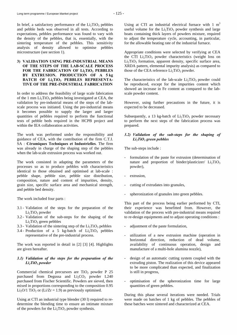
Long term programme / European blanket project - 125 -
In brief, a satisfactory performance of the Li2TiO3 pebbles and pebble beds was observed in all tests. According to expectations, pebbles performance was found to vary with the density of the pebbles, that is, essentially, with the sintering temperature of the pebbles. This sensitivity analysis of density allowed to optimise pebbles microstructure (see section 1). 3) VALIDATION USING PRE-INDUSTRIAL MEANS
OF THE STEPS OF THE LAB-SCALE PROCESS FOR THE FABRICATION OF Li2TiO3 PEBBLES BY EXTRUSION. PRODUCTION OF A 5 kg BATCH OF Li2TiO3 PEBBLES REPRESENTA-TIVE OF THE PRE-INDUSTRIAL FABRICATION
In order to address the feasibility of large scale fabrication of the 1 mm Li2TiO3 pebbles being investigated at CEA, the validation by pre-industrial means of the steps of the lab-scale process was initiated. Using the pre-industrial means it becomes possible to supply the larger and larger quantities of pebbles required to perform the functional tests of pebble beds required in the HCPB project and within the IEA collaboration activities. The work was performed under the responsibility and guidance of CEA, with the contribution of the firm C.T.I. SA : Céramiques Techniques et Industrielles. The firm was already in charge of the shaping step of the pebbles when the lab-scale extrusion process was worked out. The work consisted in adapting the parameters of the processes so as to produce pebbles with characteristics identical to those obtained and optimised at lab-scale : pebble shape, pebble size, pebble size distribution, composition, nature and content of impurities, density, grain size, specific surface area and mechanical strength, and pebble bed density. The work included four parts : 3.1 - Validation of the steps for the preparation of the
Li2TiO3 powder 3.2 - Validation of the sub-steps for the shaping of the
Li2TiO3 green pebbles 3.3 - Validation of the sintering step of the Li2TiO3 pebbles 3.4 - Production of a 5 kg-batch of Li2TiO3 pebbles
representative of the pre-industrial process. The work was reported in detail in [2] [3] [4]. Highlights are given hereafter. 3.1) Validation of the steps for the preparation of the
Li2TiO3 powder Commercial chemical precursors are TiO2 powder P 25 purchased from Degussa and Li2CO3 powder L240 purchased from Fischer Scientific. Powders are sieved, then mixed in proportions corresponding to the composition 0.95 Li2O/1 TiO2 or (Li/Zr = 1.9) as previously optimised. Using at CTI an industrial type blender (30 l) required to re-determine the blending time to ensure an intimate mixture of the powders for the Li2TiO3 powder synthesis.
Using at CTI an industrial electrical furnace with 1 m3 useful volume for the Li2TiO3 powder synthesis and large boats containing thick layers of powders mixture, required to adjust the temperature cycle, accounting, in particular, for the allowable heating rate of the industrial furnace. Appropriate conditions were selected by verifying at CEA the CTI Li2TiO3 powder characteristics (weight loss on Li2TiO3 formation, apparent density, specific surface area, XRDA pattern, elemental impurity analysis) as compared to those of the CEA reference Li2TiO3 powder. The characteristics of the lab-scale Li2TiO3 powder could be reproduced, except for the impurities content which showed an increase in Fe content as compared to the lab-scale powder content. However, using further precautions in the future, it is expected to be decreased. Subsequently, a 13 kg-batch of Li2TiO3 powder necessary to perform the next steps of the fabrication process was prepared. 3.2) Validation of the sub-steps for the shaping of
Li2TiO3 green pebbles The sub-steps include : - formulation of the paste for extrusion (determination of
nature and proportion of binder/plasticizer/ Li2TiO3 powder),
- extrusion, - cutting of extrudates into granules, - spheronization of granules into green pebbles. This part of the process being earlier performed by CTI, their experience was benefitted from. However, the validation of the process with pre-industrial means required to re-design equipments and to adjust operating conditions : - adjustment of the paste formulation, - utilization of a new extrusion machine (operation in
horizontal direction, reduction of dead volume, availability of continuous operation, design and manufacture of a multi-hole alumina nozzle),
- design of an automatic cutting system coupled with the
extruding piston. The realization of this device appeared to be more complicated than expected, and finalization is still in progress,
- optimisation of the spheronization time for large
quantities of green pebbles. During this phase several iterations were needed. Trials were made on batches of 1 kg of pebbles. The pebbles of these batches were sintered and characterized at CEA.
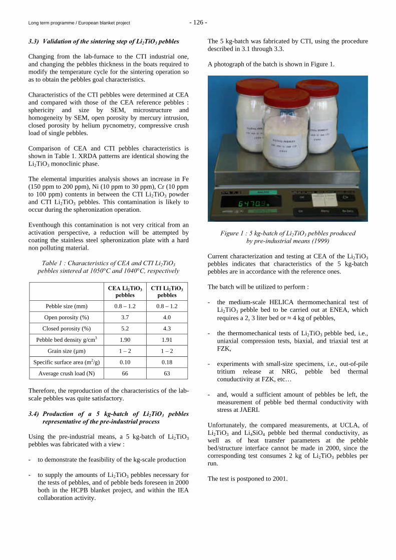
Long term programme / European blanket project - 126 -
3.3) Validation of the sintering step of Li2TiO3 pebbles Changing from the lab-furnace to the CTI industrial one, and changing the pebbles thickness in the boats required to modify the temperature cycle for the sintering operation so as to obtain the pebbles goal characteristics. Characteristics of the CTI pebbles were determined at CEA and compared with those of the CEA reference pebbles : sphericity and size by SEM, microstructure and homogeneity by SEM, open porosity by mercury intrusion, closed porosity by helium pycnometry, compressive crush load of single pebbles. Comparison of CEA and CTI pebbles characteristics is shown in Table 1. XRDA patterns are identical showing the Li2TiO3 monoclinic phase. The elemental impurities analysis shows an increase in Fe (150 ppm to 200 ppm), Ni (10 ppm to 30 ppm), Cr (10 ppm to 100 ppm) contents in between the CTI Li2TiO3 powder and CTI Li2TiO3 pebbles. This contamination is likely to occur during the spheronization operation. Eventhough this contamination is not very critical from an activation perspective, a reduction will be attempted by coating the stainless steel spheronization plate with a hard non polluting material.
Table 1 : Characteristics of CEA and CTI Li2TiO3 pebbles sintered at 1050°C and 1040°C, respectively
CEA Li2TiO3 pebbles
CTI Li2TiO3 pebbles
Pebble size (mm) 0.8 – 1.2 0.8 – 1.2
Open porosity (%) 3.7 4.0
Closed porosity (%) 5.2 4.3
Pebble bed density g/cm3 1.90 1.91
Grain size (µm) 1 – 2 1 – 2
Specific surface area (m2/g) 0.10 0.18
Average crush load (N) 66 63
Therefore, the reproduction of the characteristics of the lab-scale pebbles was quite satisfactory. 3.4) Production of a 5 kg-batch of Li2TiO3 pebbles
representative of the pre-industrial process Using the pre-industrial means, a 5 kg-batch of Li2TiO3 pebbles was fabricated with a view : - to demonstrate the feasibility of the kg-scale production - to supply the amounts of Li2TiO3 pebbles necessary for
the tests of pebbles, and of pebble beds foreseen in 2000 both in the HCPB blanket project, and within the IEA collaboration activity.
The 5 kg-batch was fabricated by CTI, using the procedure described in 3.1 through 3.3. A photograph of the batch is shown in Figure 1.
Figure 1 : 5 kg-batch of Li2TiO3 pebbles produced by pre-industrial means (1999)
Current characterization and testing at CEA of the Li2TiO3 pebbles indicates that characteristics of the 5 kg-batch pebbles are in accordance with the reference ones. The batch will be utilized to perform : - the medium-scale HELICA thermomechanical test of
Li2TiO3 pebble bed to be carried out at ENEA, which requires a 2, 3 liter bed or ≈ 4 kg of pebbles,
- the thermomechanical tests of Li2TiO3 pebble bed, i.e.,
uniaxial compression tests, biaxial, and triaxial test at FZK,
- experiments with small-size specimens, i.e., out-of-pile
tritium release at NRG, pebble bed thermal conuductivity at FZK, etc…
- and, would a sufficient amount of pebbles be left, the
measurement of pebble bed thermal conductivity with stress at JAERI.
Unfortunately, the compared measurements, at UCLA, of Li2TiO3 and Li4SiO4 pebble bed thermal conductivity, as well as of heat transfer parameters at the pebble bed/structure interface cannot be made in 2000, since the corresponding test consumes 2 kg of Li2TiO3 pebbles per run. The test is postponed to 2001.
Long term programme / European blanket project - 127 -
CONCLUSIONS 1/ Optimisation of the Li2TiO3 pebbles microstructure is
considered to be completed. 2/ All functional tests of pebble beds foreseen in 1999
could be supplied with specimens and a good behaviour of the Li2TiO3 pebbles is observed in these tests.
3/ According to expectations, no major difficulty is
encountered in the validation with pre-industrial means of the steps of the lab-scale extrusion process for the fabrication of Li2TiO3 pebbles. Thus, the characteristics of the current Li2TiO3 pebbles produced at lab-scale could be successfully reproduced.
However, additional work is needed to master and to optimise the pre-industrial process . The sensitivity of the major process parameters on the Li2TiO3 pebbles characteristics has to be evaluated. The automatic cutting system requires further development. It will be attempted to strictly limit the elemental impurities, in particular Ni. Additional aspects will be addressed such as repeatability of the production, and production yield. In order to ensure a sound comparison of Li4SiO4 and Li2TiO3 pebble beds, additional testing of HCPB blanket sub-modules and mock-ups is necessary. Supplying specimens for these tests requires that pebbles production remains at a sufficient level, namely, 5-10 kg per year. REPORTS AND PUBLICATIONS [1] J.D.Lulewicz, N.Roux, G.Piazza, J.Reimann, J.van der
Laan. Behaviour of Li2ZrO3 and Li2TiO3 pebbles relevant to their utilization in the HCPB blanket, presented at ICFRM 9, Colorado Springs, 1999
[2] J.D.Lulewicz, N.Roux. Li2TiO3 pebbles development,
interim report CEA/DTA/CEREM/CE2M/LECMA 99-DT-121 – 5/07/99
[3] J.D.Lulewicz, N.Roux. Current results of the
validation, using pre-industrial means of the steps of the lab-scale extrusion process for the fabrication of Li2TiO3 pebbles presented at CBBI-8, Colorado Springs, 1999
[4] J.D.Lulewicz, N.Roux. 1999 work on the validation
with pre-industrial means of the steps of the lab-scale process for the fabrication of Li2TiO3 pebbles by extrusion, internal report CEA/DTA/CEREM/CE2M/LECMA 99-DT-130 – 30/11/99
TASK LEADER Nicole ROUX DTA/CEREM/CE2M/LECMA CEA Saclay 91191 Gif-sur-Yvette Cedex Tél. : 33 1 69 08 25 86 Fax : 33 1 69 08 91 75 E-mail : [email protected]
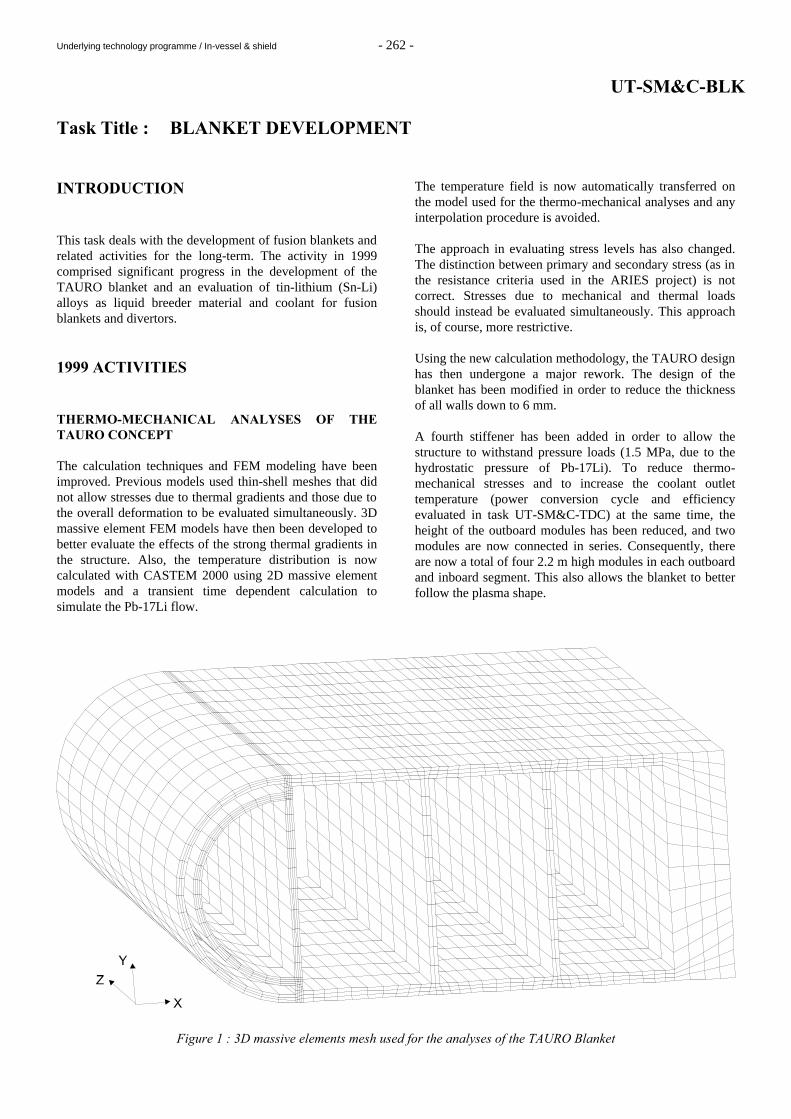
Underlying technology programme / In-vessel & shield - 262 -
UT-SM&C-BLK Task Title : BLANKET DEVELOPMENT INTRODUCTION This task deals with the development of fusion blankets and related activities for the long-term. The activity in 1999 comprised significant progress in the development of the TAURO blanket and an evaluation of tin-lithium (Sn-Li) alloys as liquid breeder material and coolant for fusion blankets and divertors. 1999 ACTIVITIES THERMO-MECHANICAL ANALYSES OF THE TAURO CONCEPT The calculation techniques and FEM modeling have been improved. Previous models used thin-shell meshes that did not allow stresses due to thermal gradients and those due to the overall deformation to be evaluated simultaneously. 3D massive element FEM models have then been developed to better evaluate the effects of the strong thermal gradients in the structure. Also, the temperature distribution is now calculated with CASTEM 2000 using 2D massive element models and a transient time dependent calculation to simulate the Pb-17Li flow.
The temperature field is now automatically transferred on the model used for the thermo-mechanical analyses and any interpolation procedure is avoided. The approach in evaluating stress levels has also changed. The distinction between primary and secondary stress (as in the resistance criteria used in the ARIES project) is not correct. Stresses due to mechanical and thermal loads should instead be evaluated simultaneously. This approach is, of course, more restrictive. Using the new calculation methodology, the TAURO design has then undergone a major rework. The design of the blanket has been modified in order to reduce the thickness of all walls down to 6 mm. A fourth stiffener has been added in order to allow the structure to withstand pressure loads (1.5 MPa, due to the hydrostatic pressure of Pb-17Li). To reduce thermo-mechanical stresses and to increase the coolant outlet temperature (power conversion cycle and efficiency evaluated in task UT-SM&C-TDC) at the same time, the height of the outboard modules has been reduced, and two modules are now connected in series. Consequently, there are now a total of four 2.2 m high modules in each outboard and inboard segment. This also allows the blanket to better follow the plasma shape.
Figure 1 : 3D massive elements mesh used for the analyses of the TAURO Blanket
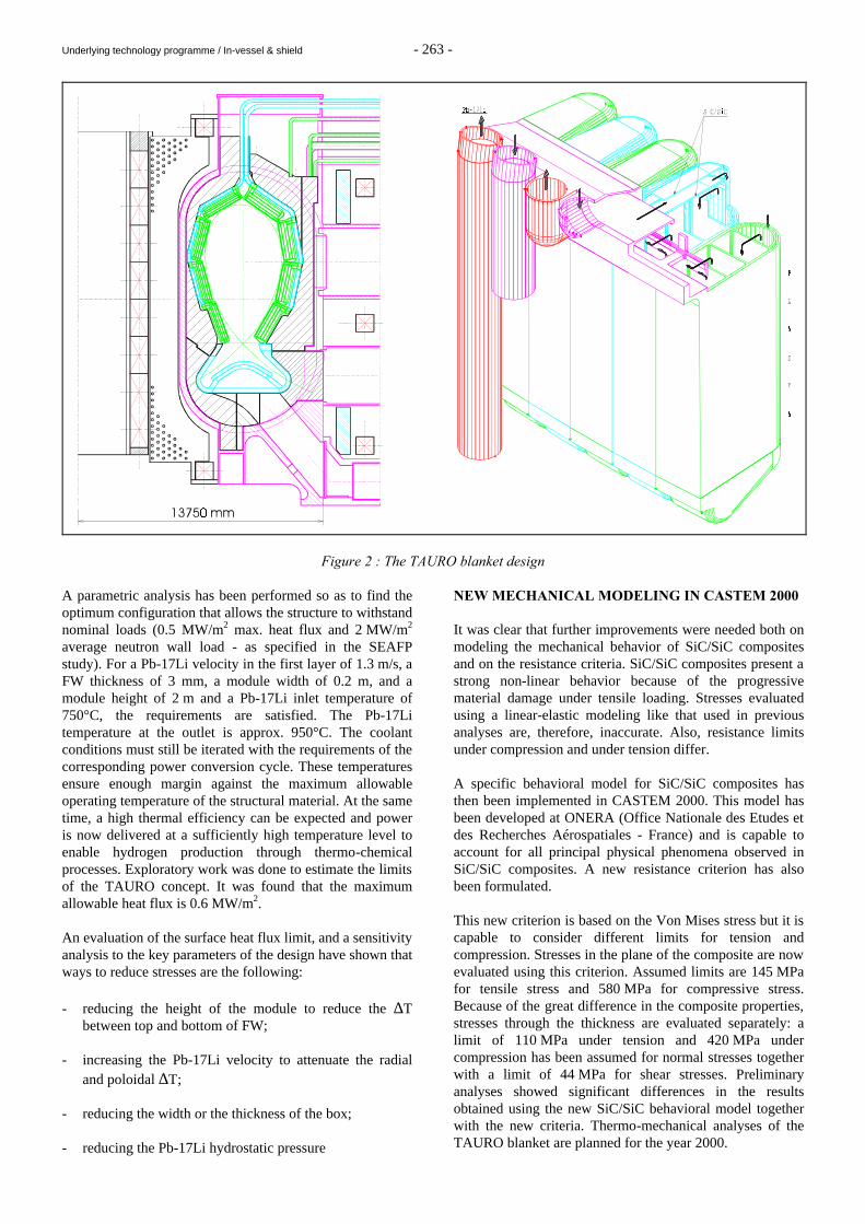
Underlying technology programme / In-vessel & shield - 263 -
Figure 2 : The TAURO blanket design A parametric analysis has been performed so as to find the optimum configuration that allows the structure to withstand nominal loads (0.5 MW/m2 max. heat flux and 2 MW/m2 average neutron wall load - as specified in the SEAFP study). For a Pb-17Li velocity in the first layer of 1.3 m/s, a FW thickness of 3 mm, a module width of 0.2 m, and a module height of 2 m and a Pb-17Li inlet temperature of 750°C, the requirements are satisfied. The Pb-17Li temperature at the outlet is approx. 950°C. The coolant conditions must still be iterated with the requirements of the corresponding power conversion cycle. These temperatures ensure enough margin against the maximum allowable operating temperature of the structural material. At the same time, a high thermal efficiency can be expected and power is now delivered at a sufficiently high temperature level to enable hydrogen production through thermo-chemical processes. Exploratory work was done to estimate the limits of the TAURO concept. It was found that the maximum allowable heat flux is 0.6 MW/m2. An evaluation of the surface heat flux limit, and a sensitivity analysis to the key parameters of the design have shown that ways to reduce stresses are the following: - reducing the height of the module to reduce the ∆T
between top and bottom of FW; - increasing the Pb-17Li velocity to attenuate the radial
and poloidal ∆T; - reducing the width or the thickness of the box; - reducing the Pb-17Li hydrostatic pressure
NEW MECHANICAL MODELING IN CASTEM 2000 It was clear that further improvements were needed both on modeling the mechanical behavior of SiC/SiC composites and on the resistance criteria. SiC/SiC composites present a strong non-linear behavior because of the progressive material damage under tensile loading. Stresses evaluated using a linear-elastic modeling like that used in previous analyses are, therefore, inaccurate. Also, resistance limits under compression and under tension differ. A specific behavioral model for SiC/SiC composites has then been implemented in CASTEM 2000. This model has been developed at ONERA (Office Nationale des Etudes et des Recherches Aérospatiales - France) and is capable to account for all principal physical phenomena observed in SiC/SiC composites. A new resistance criterion has also been formulated. This new criterion is based on the Von Mises stress but it is capable to consider different limits for tension and compression. Stresses in the plane of the composite are now evaluated using this criterion. Assumed limits are 145 MPa for tensile stress and 580 MPa for compressive stress. Because of the great difference in the composite properties, stresses through the thickness are evaluated separately: a limit of 110 MPa under tension and 420 MPa under compression has been assumed for normal stresses together with a limit of 44 MPa for shear stresses. Preliminary analyses showed significant differences in the results obtained using the new SiC/SiC behavioral model together with the new criteria. Thermo-mechanical analyses of the TAURO blanket are planned for the year 2000.
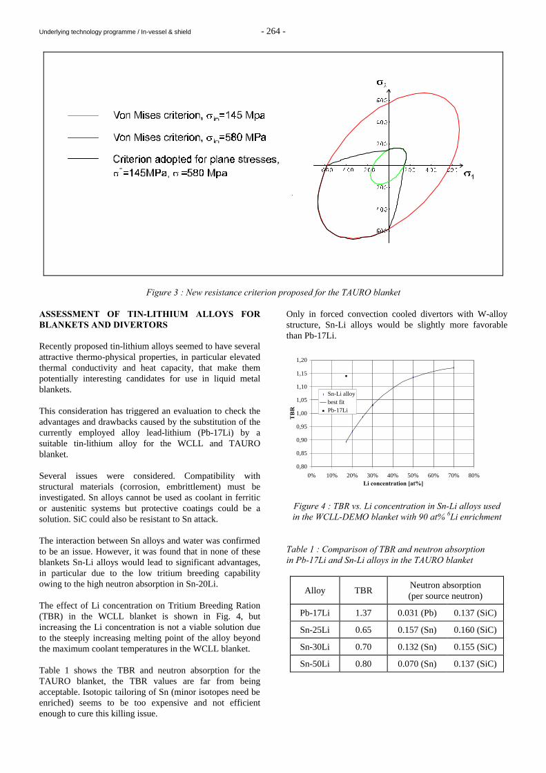
Underlying technology programme / In-vessel & shield - 264 -
Figure 3 : New resistance criterion proposed for the TAURO blanket ASSESSMENT OF TIN-LITHIUM ALLOYS FOR BLANKETS AND DIVERTORS Recently proposed tin-lithium alloys seemed to have several attractive thermo-physical properties, in particular elevated thermal conductivity and heat capacity, that make them potentially interesting candidates for use in liquid metal blankets. This consideration has triggered an evaluation to check the advantages and drawbacks caused by the substitution of the currently employed alloy lead-lithium (Pb-17Li) by a suitable tin-lithium alloy for the WCLL and TAURO blanket. Several issues were considered. Compatibility with structural materials (corrosion, embrittlement) must be investigated. Sn alloys cannot be used as coolant in ferritic or austenitic systems but protective coatings could be a solution. SiC could also be resistant to Sn attack. The interaction between Sn alloys and water was confirmed to be an issue. However, it was found that in none of these blankets Sn-Li alloys would lead to significant advantages, in particular due to the low tritium breeding capability owing to the high neutron absorption in Sn-20Li. The effect of Li concentration on Tritium Breeding Ration (TBR) in the WCLL blanket is shown in Fig. 4, but increasing the Li concentration is not a viable solution due to the steeply increasing melting point of the alloy beyond the maximum coolant temperatures in the WCLL blanket. Table 1 shows the TBR and neutron absorption for the TAURO blanket, the TBR values are far from being acceptable. Isotopic tailoring of Sn (minor isotopes need be enriched) seems to be too expensive and not efficient enough to cure this killing issue.
Only in forced convection cooled divertors with W-alloy structure, Sn-Li alloys would be slightly more favorable than Pb-17Li.
0,80
0,85
0,90
0,95
1,00
1,05
1,10
1,15
1,20
0% 10% 20% 30% 40% 50% 60% 70% 80%Li concentration [at%]
TB
R
Sn-Li alloybest fitPb-17Li
Figure 4 : TBR vs. Li concentration in Sn-Li alloys used in the WCLL-DEMO blanket with 90 at% 6Li enrichment
Table 1 : Comparison of TBR and neutron absorption in Pb-17Li and Sn-Li alloys in the TAURO blanket
Alloy TBR Neutron absorption (per source neutron)
Pb-17Li 1.37 0.031 (Pb) 0.137 (SiC)
Sn-25Li 0.65 0.157 (Sn) 0.160 (SiC)
Sn-30Li 0.70 0.132 (Sn) 0.155 (SiC)
Sn-50Li 0.80 0.070 (Sn) 0.137 (SiC)
Underlying technology programme / In-vessel & shield - 265 -
CONCLUSIONS The current reference design of the TAURO blanket assumes a surface heat flux of 0.5 MW/m2 and 2 MW/m2 average neutron wall load. In iteration with the power conversion (direct Brayton-type gas cycle) and heat exchanger requirements, suitable Pb-17Li inlet/outlet temperatures would be 450°C/860°C and the conversion efficiency would reach > 43% with a potential for further improvement. The requirements are satisfied by the following parameters: Pb-17Li velocity in the first layer of 1.3 m/s, FW thickness of 3 mm, module width of 0.2 m, and a module height of 2 m, for which the maximum Von Mises stress, normal stress and shear stress remain well within the limits. The results are preliminary because an improved mechanical model is under development. It has just been implemented in CASTEM 2000, and this new behavioral model simulating the non-linear stress-strain relation may change the stress limits. A sensitivity analysis is planned for 2000 to guide further blanket design improvements. An assessment was performed concerning the substitution of Pb-17Li by Sn-Li alloys in the WCLL and TAURO blanket and for liquid metal cooled divertors. It was found that no significant advantages can be expected. In particular the low tritium breeding capability is practically excluding this material from a use in the WCLL and TAURO blankets. PUBLICATIONS [1] H. Golfier, G. Aiello, L. Giancarli, Sensitivity analysis
to the design parameters of the TAURO blanket system, CEA report DRN/DMT SERMA/LCA/RT/99-2694/A, February 1999.
[2] H. Golfier, Performances of TAURO blanket system
associated with a liquid metal cooled divertor, Proc. ISFNT-5, September 20-24, 1999, Rome, Italy.
[3] H. Golfier, Performances of TAURO blanket system
associated with a liquid metal cooled divertor, Proc. ISFNT-5, September 20-24, 1999, Rome, Italy.
[4] G. Aiello, Modeling of SiCf/SiC composite structures
for nuclear component, Proc. ISFNT-5, September 20-24, 1999, Rome, Italy.
[5] G. Aiello, L. Giancarli, L. Gobert, E. Philippe, Y.
Poitevin, J.-F. Salavy, J. Szczepanski, A parametric analysis of the TAURO SiCf/SiC breeder blanket, CEA report DRN/DMT SERMA/LCA/RT/99-2582/A, May 1999.
[6] M. A. Fütterer, G. Aiello, F. Barbier, L. Giancarli, Y. Poitevin, A. Li Puma, G. Ruvutuso, G. Vella, Tin-lithium alloys as breeder material in water-cooled liquid metal blankets for a fusion reactor, Proc. ICFRM-9, October 11-15, 1999, Colorado Springs, CO, USA.
[7] M. A. Fütterer, G. Aiello, F. Barbier, L. Giancarli, Y.
Poitevin, P. Sardain, J. Szczepanski, A. Li Puma, G. Ruvutuso, G. Vella, Sn-Li alloys as breeder material for blankets of fusion power plants, CEA report DRN/DMT SERMA/LCA/RT/99-2710/A, December 1999.
TASK LEADER Luciano GIANCARLI DRN/DMT/SERMA/LCA CEA Saclay 91191 Gif-sur-Yvette Cedex Tél. : 33 1 69 08 21 37 Fax : 33 1 69 08 99 35 E-mail : [email protected]
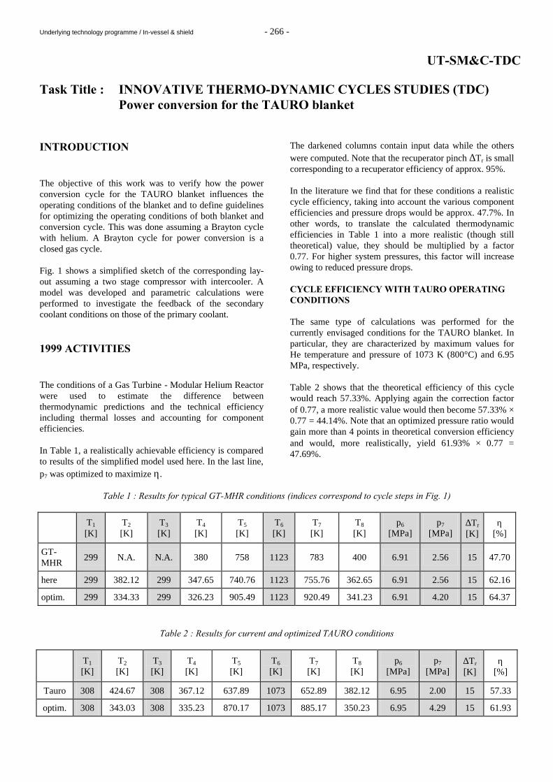
Underlying technology programme / In-vessel & shield - 266 -
UT-SM&C-TDC Task Title : INNOVATIVE THERMO-DYNAMIC CYCLES STUDIES (TDC) Power conversion for the TAURO blanket INTRODUCTION The objective of this work was to verify how the power conversion cycle for the TAURO blanket influences the operating conditions of the blanket and to define guidelines for optimizing the operating conditions of both blanket and conversion cycle. This was done assuming a Brayton cycle with helium. A Brayton cycle for power conversion is a closed gas cycle. Fig. 1 shows a simplified sketch of the corresponding lay-out assuming a two stage compressor with intercooler. A model was developed and parametric calculations were performed to investigate the feedback of the secondary coolant conditions on those of the primary coolant. 1999 ACTIVITIES The conditions of a Gas Turbine - Modular Helium Reactor were used to estimate the difference between thermodynamic predictions and the technical efficiency including thermal losses and accounting for component efficiencies. In Table 1, a realistically achievable efficiency is compared to results of the simplified model used here. In the last line, p7 was optimized to maximize η.
The darkened columns contain input data while the others were computed. Note that the recuperator pinch ∆Tr is small corresponding to a recuperator efficiency of approx. 95%. In the literature we find that for these conditions a realistic cycle efficiency, taking into account the various component efficiencies and pressure drops would be approx. 47.7%. In other words, to translate the calculated thermodynamic efficiencies in Table 1 into a more realistic (though still theoretical) value, they should be multiplied by a factor 0.77. For higher system pressures, this factor will increase owing to reduced pressure drops. CYCLE EFFICIENCY WITH TAURO OPERATING CONDITIONS The same type of calculations was performed for the currently envisaged conditions for the TAURO blanket. In particular, they are characterized by maximum values for He temperature and pressure of 1073 K (800°C) and 6.95 MPa, respectively. Table 2 shows that the theoretical efficiency of this cycle would reach 57.33%. Applying again the correction factor of 0.77, a more realistic value would then become 57.33% × 0.77 = 44.14%. Note that an optimized pressure ratio would gain more than 4 points in theoretical conversion efficiency and would, more realistically, yield 61.93% × 0.77 = 47.69%.
Table 1 : Results for typical GT-MHR conditions (indices correspond to cycle steps in Fig. 1)
T1
[K] T2
[K] T3
[K] T4
[K] T5
[K] T6
[K] T7
[K] T8
[K] p6
[MPa] p7
[MPa] ∆Tr
[K] η
[%]
GT-MHR
299 N.A. N.A. 380 758 1123 783 400 6.91 2.56 15 47.70
here 299 382.12 299 347.65 740.76 1123 755.76 362.65 6.91 2.56 15 62.16
optim. 299 334.33 299 326.23 905.49 1123 920.49 341.23 6.91 4.20 15 64.37
Table 2 : Results for current and optimized TAURO conditions
T1
[K] T2
[K] T3
[K] T4
[K] T5
[K] T6
[K] T7
[K] T8
[K] p6
[MPa] p7
[MPa] ∆Tr
[K] η
[%]
Tauro 308 424.67 308 367.12 637.89 1073 652.89 382.12 6.95 2.00 15 57.33
optim. 308 343.03 308 335.23 870.17 1073 885.17 350.23 6.95 4.29 15 61.93
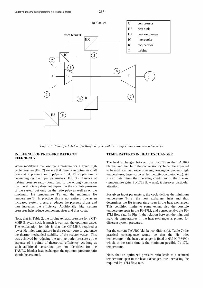
Underlying technology programme / In-vessel & shield - 267 -
Figure 1 : Simplified sketch of a Brayton cycle with two stage compressor and intercooler INFLUENCE OF PRESSURE RATIO ON EFFICIENCY When modifying the low cycle pressure for a given high cycle pressure (Fig. 2) we see that there is an optimum in all cases at a pressure ratio p6/p7 = 1.64. This optimum is depending on the input parameters. Fig. 3 (influence of turbine pressure ratio) could lead to the wrong conclusion that the efficiency does not depend on the absolute pressure of the system but only on the ratio p6/p7 as well as on the maximum He temperature T6 and the minimum He temperature T1. In practice, this is not entirely true as an increased system pressure reduces the pressure drops and thus increases the efficiency. Additionally, high system pressures help reduce component sizes and thus costs. Note, that in Table 2, the turbine exhaust pressure for a GT-MHR Brayton cycle is much lower than the optimum value. The explanation for this is that the GT-MHR required a lower He inlet temperature in the reactor core to guarantee the thermo-mechanical stability of the reactor vessel. This was achieved by reducing the turbine outlet pressure at the expense of 4 points of theoretical efficiency. As long as such additional constraints are not identified for the TAURO blanket heat exchanger, the optimum pressure ratio should be assumed.
TEMPERATURES IN HEAT EXCHANGER The heat exchanger between the Pb-17Li in the TAURO blanket and the He in the conversion cycle can be expected to be a difficult and expensive engineering component (high temperatures, large surfaces, hermeticity, corrosion etc.). As it also determines the operating conditions of the blanket (temperature gain, Pb-17Li flow rate), it deserves particular attention. For given input parameters, the cycle defines the minimum temperature T5 at the heat exchanger inlet and thus determines the He temperature span in the heat exchanger. This condition limits to some extent also the possible temperature span in the Pb-17Li, and consequently, the Pb-17Li flow-rate. In Fig. 4, the relation between the min. and max. He temperatures in the heat exchanger is plotted for different system pressures. For the current TAURO blanket conditions (cf. Table 2) the practical consequence would be that the He inlet temperature in the heat exchanger is fixed at 637 K (364°C) which, at the same time is the minimum possible Pb-17Li temperature. Note, that an optimized pressure ratio leads to a reduced temperature span in the heat exchanger, thus increasing the required Pb-17Li flow-rate.
~ ~ ~
C T
HX
HS
R
5
to blanket
from blanket
C compressor
HS heat sink
HX heat exchanger
IC intercooler
R recuperator
T turbine
IC
C
6 3
2
4 7
8
1
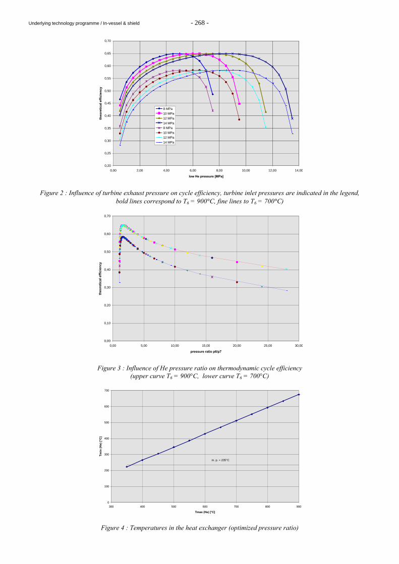
Underlying technology programme / In-vessel & shield - 268 -
0,20
0,25
0,30
0,35
0,40
0,45
0,50
0,55
0,60
0,65
0,70
0,00 2,00 4,00 6,00 8,00 10,00 12,00 14,00
low He pressure [MPa]
theo
reti
cal e
ffic
ien
cy
8 MPa
10 MPa
12 MPa
14 MPa
8 MPa
10 MPa
12 MPa
14 MPa
Figure 2 : Influence of turbine exhaust pressure on cycle efficiency, turbine inlet pressures are indicated in the legend, bold lines correspond to T6 = 900°C, fine lines to T6 = 700°C)
0,00
0,10
0,20
0,30
0,40
0,50
0,60
0,70
0,00 5,00 10,00 15,00 20,00 25,00 30,00
pressure ratio p6/p7
theo
reti
cal e
ffic
ien
cy
Figure 3 : Influence of He pressure ratio on thermodynamic cycle efficiency (upper curve T6 = 900°C, lower curve T6 = 700°C)
0
100
200
300
400
500
600
700
300 400 500 600 700 800 900
Tmax (He) [°C]
Tm
in (
He)
[°C
]
m. p. = 235°C
Figure 4 : Temperatures in the heat exchanger (optimized pressure ratio)
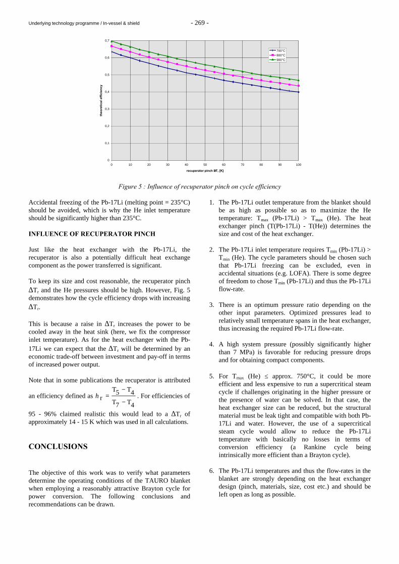
Underlying technology programme / In-vessel & shield - 269 -
0
0,1
0,2
0,3
0,4
0,5
0,6
0,7
0 10 20 30 40 50 60 70 80 90 100
recuperator pinch ∆∆Tr [K]
theo
reti
cal e
ffic
ien
cy
700°C
800°C
900°C
Figure 5 : Influence of recuperator pinch on cycle efficiency Accidental freezing of the Pb-17Li (melting point = 235°C) should be avoided, which is why the He inlet temperature should be significantly higher than 235°C. INFLUENCE OF RECUPERATOR PINCH Just like the heat exchanger with the Pb-17Li, the recuperator is also a potentially difficult heat exchange component as the power transferred is significant. To keep its size and cost reasonable, the recuperator pinch ∆Tr and the He pressures should be high. However, Fig. 5 demonstrates how the cycle efficiency drops with increasing ∆Tr. This is because a raise in ∆Tr increases the power to be cooled away in the heat sink (here, we fix the compressor inlet temperature). As for the heat exchanger with the Pb-17Li we can expect that the ∆Tr will be determined by an economic trade-off between investment and pay-off in terms of increased power output. Note that in some publications the recuperator is attributed
an efficiency defined as 4T7T
4T5Tr
−
−=η . For efficiencies of
95 - 96% claimed realistic this would lead to a ∆Tr of approximately 14 - 15 K which was used in all calculations. CONCLUSIONS The objective of this work was to verify what parameters determine the operating conditions of the TAURO blanket when employing a reasonably attractive Brayton cycle for power conversion. The following conclusions and recommendations can be drawn.
1. The Pb-17Li outlet temperature from the blanket should be as high as possible so as to maximize the He temperature: Tmax (Pb-17Li) > Tmax (He). The heat exchanger pinch (T(Pb-17Li) - T(He)) determines the size and cost of the heat exchanger.
2. The Pb-17Li inlet temperature requires Tmin (Pb-17Li) >
Tmin (He). The cycle parameters should be chosen such that Pb-17Li freezing can be excluded, even in accidental situations (e.g. LOFA). There is some degree of freedom to chose Tmin (Pb-17Li) and thus the Pb-17Li flow-rate.
3. There is an optimum pressure ratio depending on the
other input parameters. Optimized pressures lead to relatively small temperature spans in the heat exchanger, thus increasing the required Pb-17Li flow-rate.
4. A high system pressure (possibly significantly higher
than 7 MPa) is favorable for reducing pressure drops and for obtaining compact components.
5. For Tmax (He) ≤ approx. 750°C, it could be more
efficient and less expensive to run a supercritical steam cycle if challenges originating in the higher pressure or the presence of water can be solved. In that case, the heat exchanger size can be reduced, but the structural material must be leak tight and compatible with both Pb-17Li and water. However, the use of a supercritical steam cycle would allow to reduce the Pb-17Li temperature with basically no losses in terms of conversion efficiency (a Rankine cycle being intrinsically more efficient than a Brayton cycle).
6. The Pb-17Li temperatures and thus the flow-rates in the
blanket are strongly depending on the heat exchanger design (pinch, materials, size, cost etc.) and should be left open as long as possible.

Underlying technology programme / In-vessel & shield - 270 -
PUBLICATIONS [1] M. A. Fütterer, Power conversion for the TAURO
blanket, CEA report DRN/DMT SERMA/LCA/RT/99-2628/A, June 1999.
[2] Y. Severi, Fusion power reactor preliminary study,
CEA report DRN/DER/STPI 99-015, May 1999.
TASK LEADER Michael A. FÜTTERER DRN/DMT/SERMA/LCA CEA Saclay 91191 Gif-sur-Yvette Cedex Tél. : 33 1 69 08 36 36 Fax : 33 1 69 08 99 35 E-mail : [email protected]
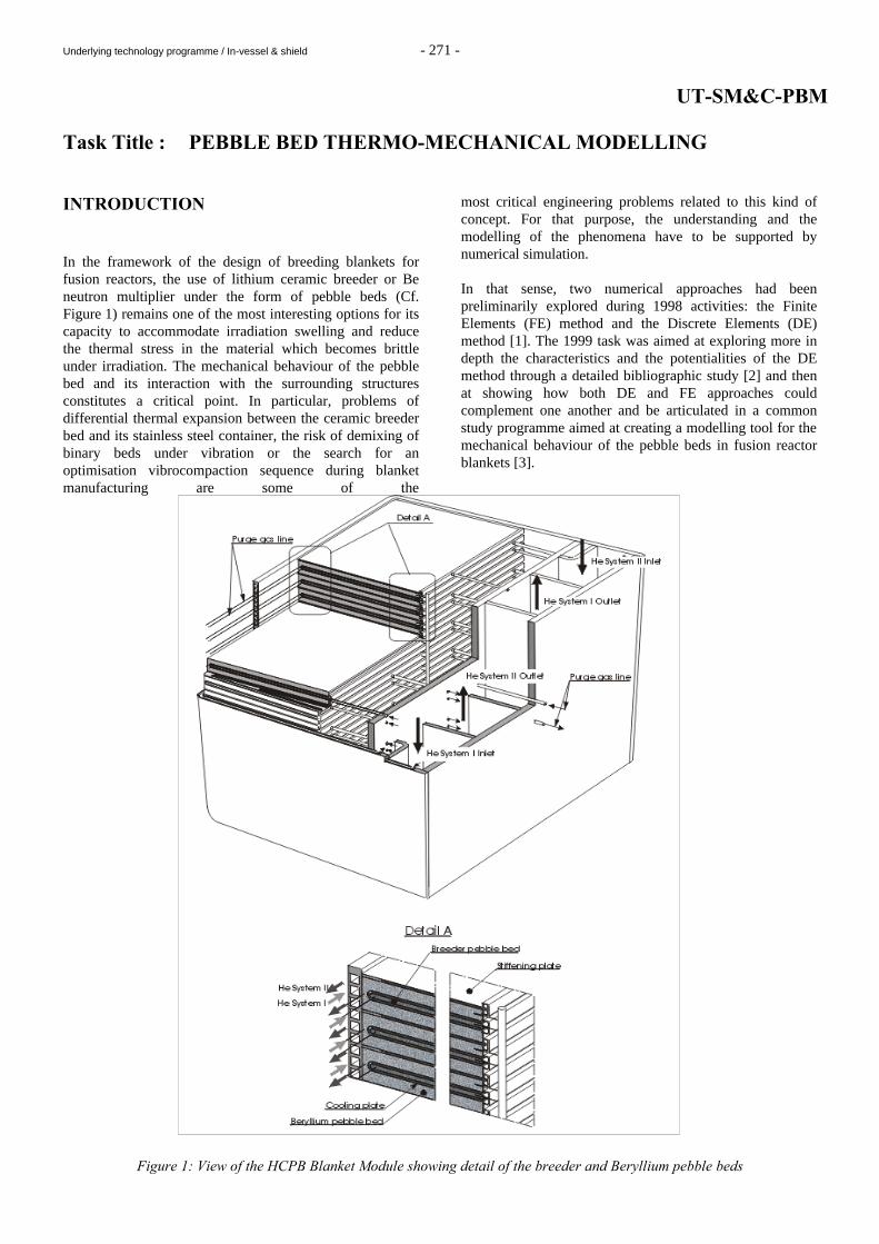
Underlying technology programme / In-vessel & shield - 271 -
UT-SM&C-PBM Task Title : PEBBLE BED THERMO-MECHANICAL MODELLING INTRODUCTION In the framework of the design of breeding blankets for fusion reactors, the use of lithium ceramic breeder or Be neutron multiplier under the form of pebble beds (Cf. Figure 1) remains one of the most interesting options for its capacity to accommodate irradiation swelling and reduce the thermal stress in the material which becomes brittle under irradiation. The mechanical behaviour of the pebble bed and its interaction with the surrounding structures constitutes a critical point. In particular, problems of differential thermal expansion between the ceramic breeder bed and its stainless steel container, the risk of demixing of binary beds under vibration or the search for an optimisation vibrocompaction sequence during blanket manufacturing are some of the
most critical engineering problems related to this kind of concept. For that purpose, the understanding and the modelling of the phenomena have to be supported by numerical simulation. In that sense, two numerical approaches had been preliminarily explored during 1998 activities: the Finite Elements (FE) method and the Discrete Elements (DE) method [1]. The 1999 task was aimed at exploring more in depth the characteristics and the potentialities of the DE method through a detailed bibliographic study [2] and then at showing how both DE and FE approaches could complement one another and be articulated in a common study programme aimed at creating a modelling tool for the mechanical behaviour of the pebble beds in fusion reactor blankets [3].
Figure 1: View of the HCPB Blanket Module showing detail of the breeder and Beryllium pebble beds
Underlying technology programme / In-vessel & shield - 272 -
1999 ACTIVITIES A detailed bibliographic study on the DE methods and their relationship with the FE approach has been first performed [2]. The Discrete Element method which is an outgrowth of molecular dynamics simulations has been independently and widely developed since the 70s to study the behaviour of rock masses and granular materials. Its specificity is to describe the dynamic behaviour of a set of particles which interact through specific contact laws. The variety of the contact laws which are considered and modelled today in DE simulations allows the modelling of various problems like, for example, the flow of a particulate material from wedge shaped hoppers, soil creep, the local fracture analysis of a concrete slab subjected to impact loading, the seismic analysis of an edifice, the vibrocompaction of a granular material or the thermo-mechanical behaviour of a pebble bed. In the field of mechanics applied to nuclear reactors, the FE have been used for many years with success. Their position remains uncontested for structural mechanics (vessel, internals, cladding,…). But for some items related to the mechanics of granular materials (breeder material, neutron multiplier,…), the DE method appears to be a serious complement to FE models or to the only experiments. It opens indeed a local information level which is inaccessible for FE models and allows to model numerically some phenomena like vibrocompaction which have been studied up to now only experimentally. The above conclusion is based more precisely on the following points which have been demonstrated and detailed in [2] : - The DE method is able to model the vibrocompaction
of a pebble bed and to access to local information like the void fraction and the contact forces between particles. The possibility to repeat numerical simulations by varying the characteristics of the particles (shape, size, friction coefficient) or the vibration sequence (frequency, amplitude) appears interesting for the search of an optimum. Moreover, progress on contact detection algorithms and parallel calculation lead to the possibility to simulate systems up to 250.000 particles, which allow now to envisage the simulation of real technological problems.
- In the frame of the mechanical modelisation of a
granular material through a FE continuous model, the DE methods could allow to access an additional information level in a localized area: microscopical information like contact forces, void fraction or particle displacement could, for example, be found in a local area around a discontinuity. In such an approach, the local DE model takes its boundary conditions from the global continuous FE model.
- The DE method is capable to simulate the dynamic fracture of a material - for example, a ceramic pebble subjected to excessive contact forces - and, more generally, to manage the contact detection inside the granular assembly.
- The DE method appears also to be a good support tool
for the determination and qualification of continuous phenomenological models of granular materials. It allows indeed to perform a large number of numerical simulations of expensive experimental tests, the input parameters of the DE model (statistical distribution of the particles size, friction coefficient,…) being determined through an identification process based on real experiments in laboratory.
On the basis of the conclusion of this study, we have proposed a comprehensive development programme for the modelisation of the pebble beds in fusion reactor blankets [3]. This programme consists of the three following points: i) Evaluation of the most advanced 3D discrete element
codes for the modelisation of the vibrocompaction sequence.
ii) Development of a DE/FE coupling for the two
following purposes: a) Homogenisation of the mechanical behaviour of the granular material: macroscopic parameters are determined from experimental or numerical (DE) tests on the pebble bed. These parameters are then used in a FE model. b) Development of a FE thermo-mechanical model with coupling with DE method locally for evaluation of microscopic parameters (void fraction, contact forces,…). The local DE model takes its boundary conditions from the global FE model. Local evaluation of the microscopic parameters should be reserved for critical areas (stress concentration area, singularities,…).
iii) Experimental evaluation of the thermal conductivity of
vibrocompacted beds. CONCLUSION A detailed bibliographic study has shown that the development of the capacity of numerical simulations allows today to use the DE method for the modelisation of real technical problems like the behaviour of pebble beds in breeding blankets. Such a method allows especially to simulate and optimise the vibrocompaction sequence. The precise potential of the DE method have now to be directly analysed for the most advanced available DE codes (MIT/Boston, Sandia,…). The thermo-mechanical behaviour of pebble beds could be modelled through a DE approach or through continuous phenomenological laws inserted in FE models.
Underlying technology programme / In-vessel & shield - 273 -
The information level extraction in both cases is different and this year’s activity has actually shown the complementarity of both approaches. This led to the definition of a programme study for the modelisation of the mechanical behaviour of the pebble beds using a coupling between DE and FE methods. Experimental studies dedicated to thermal conductivity measurement of a vibrocompacted granular materials allow also to complete the programme which should, at the end, offer an advanced tool for the modelisation of the mechanical behaviour of pebble beds in breeding blankets. REPORTS AND PUBLICATIONS [1] Y. Poitevin, M. Eid, L. Giancarli, « Evaluation of
Numerical Approaches to Modelise the Mechanical Behaviour of Fusion Blanket Pebble Beds », CEA report SERMA/LCA/RT/98-2431/B, April 1999.
[2] Y. Poitevin, J Bergeron, « Intérêts et Applications de
la Simulation Numérique par la Méthode des Eléménts Discrets », CEA report SERMA/LCA/RT/99-2656/A, September 1999.
[3] Y. Poitevin et al., « Proposition d’un Programme
d’Etude et de Modélisation du Comportement Mécanique des Lits de Billes dans les Réacteurs à Fusion », CEA report SERMA/LCA/RT/00-2750/A, February 2000.
TASK LEADER Yves POITEVIN DRN/DMT/SERMA CEA Saclay 91191 Gif-sur-Yvette Cedex Tél. : 33 1 69 08 31 86 Fax : 33 1 69 08 99 35 E-mail : [email protected]
Underlying technology programme / In-vessel & shield - 274 -
UT-SM&C-COAT Task Title : DEVELOPMENT OF AN OXIDE LAYER ON A Fe-Al CVD
COATING INTRODUCTION One of the methods developed for the fabrication of the Tritium Permeation Barrier (TPB) required in the WCLL blanket is the deposition of a Fe-Al/Al2O3 coating by Chemical Vapour Deposition (CVD) performed in two steps [1] : 1. a pack cementation treatment performed at 750°C in a
Fe-Al base cement in order to form a Fe-Al coating of 6-7 µm thick,
2. a MOCVD deposition (CVD using metalorganic
precursors) performed between 400 and 450°C using the Pyrosol method in order to deposit an Al2O3 top layer of about 1 µm thick.
The interest of the Fe-Al/Al2O3 material can be considered for barrier applications in other fields such as petrochemistry or petroleum industry where different problems can be concerned (hydrogen embrittlement, sulfurization, carburization...). The feasability of forming the oxide layer using oxidizing treatments instead of deposition processes is studied because such treatments could be easier to apply on any geometry of components. So, the aim of this study is to check the possibility of forming the oxide layer, which seems to be responsible of the permeation reduction, by oxidizing directly the Fe-Al CVD coating. Different methods involving a Pyrosol of water, an ion oxidation, a « classic » oxidation or an « in situ » oxidation have been tested at temperatures compatible with the heat treatment state of the martensitic steel substrate (< 750°C).
1999 ACTIVITIES The different treatments have been all tested using the same Fe-Al reference coating performed by pack cementation on the T91 martensitic steel. The quality of the coating and the nature of its surface after oxidation have been investigated on specimens using SEM observation on surface and cross-section, EDS and ESCA analyses, X Ray Diffraction analysis performed in standard conditions to control the evolution of the Fe-Al material itself due to the oxidation treatment conditions and XRD analysis performed at glazing incidences to control the formation of compounds at the surface.
« CLASSIC » AND « IN SITU » OXIDATION METHODS The « classic » oxidation has been performed after the pack cementation treatment in a standard Heraus furnace used for thermal treatments. Treatments of 1 hour under air have been tested for a temperature of 730°C. The « in situ » oxidation has been performed during the pack cementation treatment itself which is so divided in two steps : - the first step is performed in the standard conditions
defined in the procedure for the Fe-Al deposition [1] using an argon flow rate during 1 hour,
- a second step of 1 hour is added, by replacing the argon
by air in order to work in a oxidizing atmosphere, all the other parameters remaining the same (temperature of 750°C, pressure level of 5 mbar...).
The advantage of this route is to perform the whole treatment « Fe-Al deposition + oxidation » in the same device and in a same operation instead of two different operations as it is the case of the « classic » oxidation (no additional handling of components, no cleaning operation between the different operations...). The coatings obtained by both treatments have been compared to the Fe-Al reference coating (non oxidized). The surface morphology observed by SEM appears to be slightly different after oxidation, especially in the case of the « in situ » oxidation which leads to a thicker coating (8.5 µm against 6.5 µm) : in this case, the Fe-Al deposition seems to still go on, even in the oxidizing atmosphere, since the substrate is still in contact with the cement during this step. The qualitative analysis performed by EDS on the surface clearly shows the presence of an oxygen peak in both cases of oxidized coatings whereas it is normally absent for the as-deposited Fe-Al reference coating. The X Ray Diffraction analysis performed at glazing incidences (from 0.5 to 2.5°) reveals the presence of peaks relative to alumina for the « classic » and the « in situ » oxidations whereas it is not the case for the Fe-Al reference coating. These results are confirmed by the ESCA analysis that has been performed in two steps : firstly directly on the surface and secondly after an ion abrasion of about 5 nm in order to eliminate the natural contamination layer and to analyse the first layers of the coating.
Underlying technology programme / In-vessel & shield - 275 -
The values obtained for the Fe/Al ratio show that the very surface of the coatings presents a strong enrichment in aluminum. In all cases, the aluminum and the iron are under an oxide form at the surface, respectively Al2O3 and Fe2O3. This means that the Fe-Al reference coating itself has a native oxide layer at the surface which seems to be promissing from self-healing considerations. For the oxidized coatings, all the aluminum is still present as oxide after the ion abrasion, whereas a part of it is met as metal in the case of the reference coating. Concerning the Fe element, it is totally metallic in the case of the reference coating after the abrasion but it is partially oxidized in the two other cases. All these results show that the formation of a superficial layer consisted of Al2O3 and Fe2O3 on the Fe-Al coating can be obtained either by an « in situ » or « classic » method. The thickness of the oxidized layer is under evaluation. TREATMENT USING THE PYROLYSIS OF A WATER AEROSOL The feasability of the method, which principle is described in [1], has been tested using a static Pyrosol furnace. The idea is to spray a vapour of water on the heated substrate in order to get an oxidation phenomenon. Similar methods are actually run for industrial applications for the densification of anodized layers by alumina growth. A temperature of 550°C has been tested for a total time of 1 hour. The colour of the Fe-Al coating changed from grey to yellow colour but the control performed on the surface by EDS analysis didn’t exhibit any oxygen peak. The method tested in this parameter range didn’t succeed in the oxidation of the Fe-Al coating. ION OXIDATION USING A O2 PLASMA ASSISTED TREATMENT The feasability of the method has been tested in a pilot-scale Plasma-Assisted CVD (PACVD) reactor equiped with a low frequency power supply. The treatment has been performed under reduced pressure (~ 0.2 mbar) using O2 as reactive gas. A power of 400 W has been delivered for the plasma assistance but no additive heating was used. A treatment of 3 hours has been tested. The tested conditions have not been successfull from an oxidation point of view : the different physicochemical and metallurgical controls have shown no fundamental change of the Fe-Al coating. The spectrum obtained by the EDS analysis performed on the surface does not exibit any peak relative to the presence of oxygen and the XRD analysis performed at glow incidence does no reveal the presence of oxide compounds. It is thought that the temperature produced by the plasma alone was not sufficiant.
CONCLUSIONS The method based on the Pyrosol of water is not relevant for this kind of treatment. The ion oxidation performed without thermal assistance is not successfull in the tested conditions, but complementary tests will be carried out next year using an additional heating device so to get a combined effect of temperature and plasma assistance on the surface reactivity of the Fe-Al coating. On the opposite, the « in situ » oxidation method performed at 750°C during the pack-cementation process itself seems to be interesting since an oxide layer consisted of Al2O3 and Fe2O3 is formed. These results are similar to what can be obtained with a « classic » oxidation performed in the same temperature range using a heat treatment under air. The main advantage of this route is that the deposition of the Fe-Al coating and its oxidation can be performed in the same operation. In addition, these investigations have shown the presence of a thin native oxide layer (< 5 nm) on the Fe-Al as-deposited coating which can be promissing for the self-healing property required for the barrier coating. The fabrication of coated specimens will be carried out next year to evaluate and compare the barrier efficiency of this material to that of the Fe-Al/Al2O3 reference material qualified in the WPA4 task. REPORTS AND PUBLICATIONS [1] C. Chabrol, F. Schuster « Coating qualification
report » Note technique DEM n° 98/32, 15 july 1998 [2] C. Chabrol, V. Bénévent, F. Schuster « Development
of an oxide layer on a Fe-Al CVD coating » Note technique DEM n° 99/94, 20 dec. 1999
TASK LEADER Claude CHABROL DTA/DEM/SGM CEA Grenoble 17, rue des martyrs 38054 Grenoble Cedex 9 Tél. : 33 4 76 88 99 77 Fax : 33 4 76 88 99 85 E-mail : [email protected]
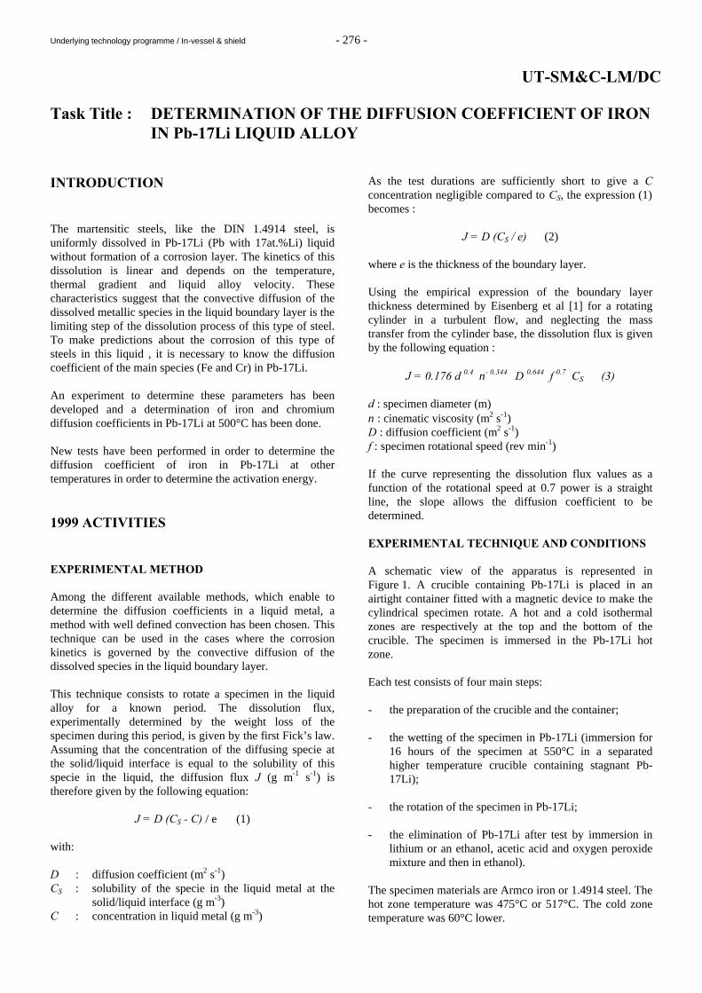
Underlying technology programme / In-vessel & shield - 276 -
UT-SM&C-LM/DC Task Title : DETERMINATION OF THE DIFFUSION COEFFICIENT OF IRON
IN Pb-17Li LIQUID ALLOY INTRODUCTION The martensitic steels, like the DIN 1.4914 steel, is uniformly dissolved in Pb-17Li (Pb with 17at.%Li) liquid without formation of a corrosion layer. The kinetics of this dissolution is linear and depends on the temperature, thermal gradient and liquid alloy velocity. These characteristics suggest that the convective diffusion of the dissolved metallic species in the liquid boundary layer is the limiting step of the dissolution process of this type of steel. To make predictions about the corrosion of this type of steels in this liquid , it is necessary to know the diffusion coefficient of the main species (Fe and Cr) in Pb-17Li. An experiment to determine these parameters has been developed and a determination of iron and chromium diffusion coefficients in Pb-17Li at 500°C has been done. New tests have been performed in order to determine the diffusion coefficient of iron in Pb-17Li at other temperatures in order to determine the activation energy.
1999 ACTIVITIES EXPERIMENTAL METHOD Among the different available methods, which enable to determine the diffusion coefficients in a liquid metal, a method with well defined convection has been chosen. This technique can be used in the cases where the corrosion kinetics is governed by the convective diffusion of the dissolved species in the liquid boundary layer. This technique consists to rotate a specimen in the liquid alloy for a known period. The dissolution flux, experimentally determined by the weight loss of the specimen during this period, is given by the first Fick’s law. Assuming that the concentration of the diffusing specie at the solid/liquid interface is equal to the solubility of this specie in the liquid, the diffusion flux J (g m-1 s-1) is therefore given by the following equation:
J = D (CS - C) / e (1) with: D : diffusion coefficient (m2 s-1) CS : solubility of the specie in the liquid metal at the
solid/liquid interface (g m-3) C : concentration in liquid metal (g m-3)
As the test durations are sufficiently short to give a C concentration negligible compared to CS, the expression (1) becomes :
J = D (CS / e) (2) where e is the thickness of the boundary layer. Using the empirical expression of the boundary layer thickness determined by Eisenberg et al [1] for a rotating cylinder in a turbulent flow, and neglecting the mass transfer from the cylinder base, the dissolution flux is given by the following equation :
J = 0.176 d 0.4 ν- 0.344 D 0.644 f 0.7 CS (3) d : specimen diameter (m) ν : cinematic viscosity (m2 s-1) D : diffusion coefficient (m2 s-1) f : specimen rotational speed (rev min-1) If the curve representing the dissolution flux values as a function of the rotational speed at 0.7 power is a straight line, the slope allows the diffusion coefficient to be determined. EXPERIMENTAL TECHNIQUE AND CONDITIONS A schematic view of the apparatus is represented in Figure 1. A crucible containing Pb-17Li is placed in an airtight container fitted with a magnetic device to make the cylindrical specimen rotate. A hot and a cold isothermal zones are respectively at the top and the bottom of the crucible. The specimen is immersed in the Pb-17Li hot zone. Each test consists of four main steps: - the preparation of the crucible and the container; - the wetting of the specimen in Pb-17Li (immersion for
16 hours of the specimen at 550°C in a separated higher temperature crucible containing stagnant Pb-17Li);
- the rotation of the specimen in Pb-17Li; - the elimination of Pb-17Li after test by immersion in
lithium or an ethanol, acetic acid and oxygen peroxide mixture and then in ethanol).
The specimen materials are Armco iron or 1.4914 steel. The hot zone temperature was 475°C or 517°C. The cold zone temperature was 60°C lower.
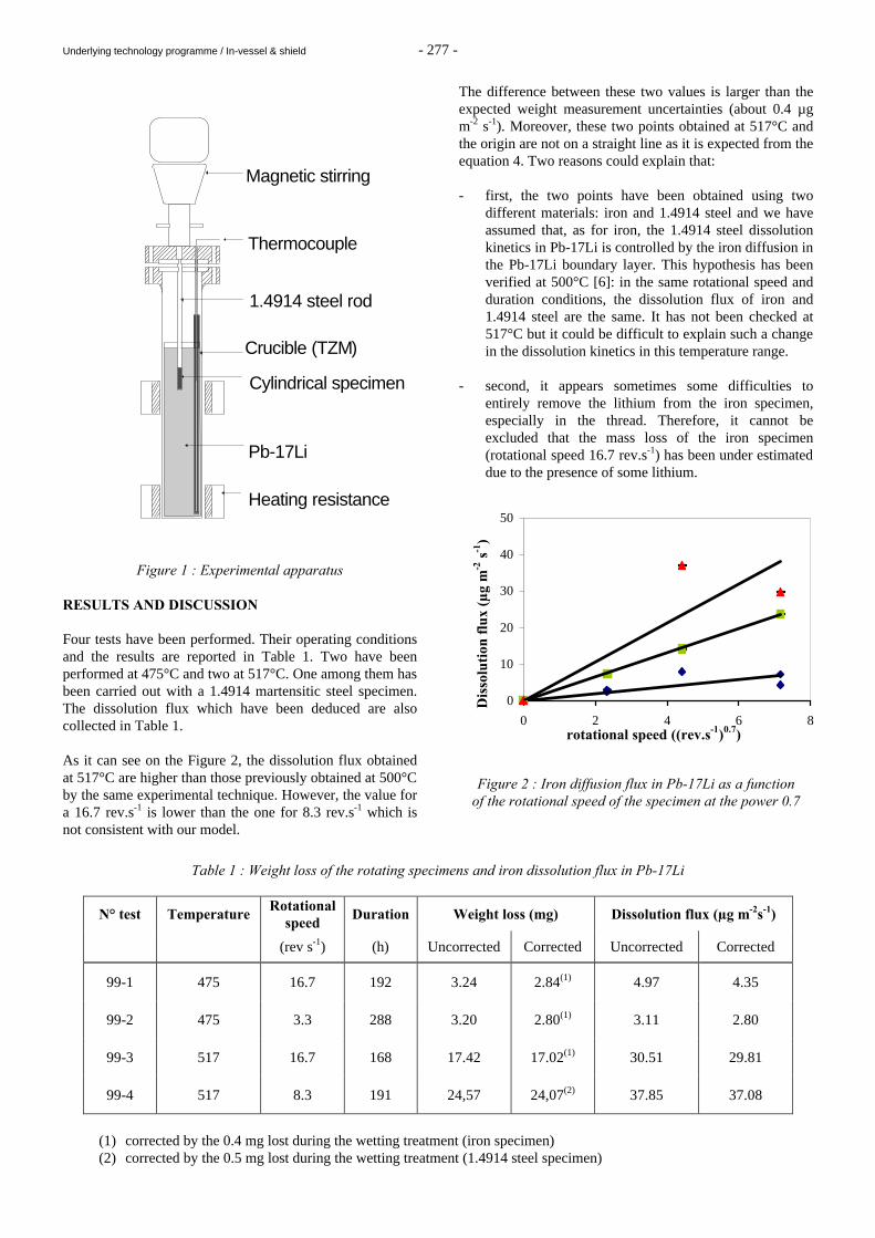
Underlying technology programme / In-vessel & shield - 277 -
Magnetic stirring
Thermocouple
1.4914 steel rod
Heating resistance
Pb-17Li
Cylindrical specimen
Crucible (TZM)
Figure 1 : Experimental apparatus
RESULTS AND DISCUSSION Four tests have been performed. Their operating conditions and the results are reported in Table 1. Two have been performed at 475°C and two at 517°C. One among them has been carried out with a 1.4914 martensitic steel specimen. The dissolution flux which have been deduced are also collected in Table 1. As it can see on the Figure 2, the dissolution flux obtained at 517°C are higher than those previously obtained at 500°C by the same experimental technique. However, the value for a 16.7 rev.s-1 is lower than the one for 8.3 rev.s-1 which is not consistent with our model.
The difference between these two values is larger than the expected weight measurement uncertainties (about 0.4 µg m-2 s-1). Moreover, these two points obtained at 517°C and the origin are not on a straight line as it is expected from the equation 4. Two reasons could explain that: - first, the two points have been obtained using two
different materials: iron and 1.4914 steel and we have assumed that, as for iron, the 1.4914 steel dissolution kinetics in Pb-17Li is controlled by the iron diffusion in the Pb-17Li boundary layer. This hypothesis has been verified at 500°C [6]: in the same rotational speed and duration conditions, the dissolution flux of iron and 1.4914 steel are the same. It has not been checked at 517°C but it could be difficult to explain such a change in the dissolution kinetics in this temperature range.
- second, it appears sometimes some difficulties to
entirely remove the lithium from the iron specimen, especially in the thread. Therefore, it cannot be excluded that the mass loss of the iron specimen (rotational speed 16.7 rev.s-1) has been under estimated due to the presence of some lithium.
Figure 2 : Iron diffusion flux in Pb-17Li as a function
of the rotational speed of the specimen at the power 0.7
Table 1 : Weight loss of the rotating specimens and iron dissolution flux in Pb-17Li
N° test Temperature Rotational
speed Duration Weight loss (mg) Dissolution flux (µg m-2s-1)
(rev s-1) (h) Uncorrected Corrected Uncorrected Corrected
99-1 475 16.7 192 3.24 2.84(1) 4.97 4.35
99-2 475 3.3 288 3.20 2.80(1) 3.11 2.80
99-3 517 16.7 168 17.42 17.02(1) 30.51 29.81
99-4 517 8.3 191 24,57 24,07(2) 37.85 37.08
(1) corrected by the 0.4 mg lost during the wetting treatment (iron specimen) (2) corrected by the 0.5 mg lost during the wetting treatment (1.4914 steel specimen)
517°C
0
10
20
30
40
50
0 2 4 6 8rotational speed ((rev.s-1)0.7)
Dis
solu
tion
flu
x (µ
g m
-2 s
-1)
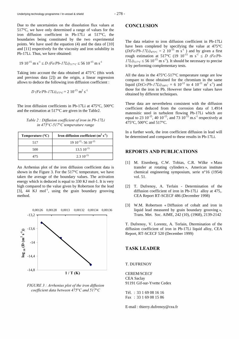
Underlying technology programme / In-vessel & shield - 278 -
Due to the uncertainties on the dissolution flux values at 517°C, we have only determined a range of values for the iron diffusion coefficient in Pb-17Li at 517°C, the boundaries being constituted by the two experimental points. We have used the equation (4) and the data of [10] and [11] respectively for the viscosity and iron solubility in Pb-17Li. Thus, we have obtained: 19 10-15 m s-1 ≤ D (Fe/Pb-17Li)517°C ≤ 56 10-15 m s-1 Taking into account the data obtained at 475°C (this work and previous data [2]) an the origin, a linear regression allows to deduce the following iron diffusion coefficient : D (Fe/Pb-17Li)475°C = 2 10-15 m2 s-1 The iron diffusion coefficients in Pb-17Li at 475°C, 500°C and the estimation at 517°C are given in the Table2.
Table 2 : Diffusion coefficient of iron in Pb-17Li in 475°C-517°C temperature range
Temperature (°C) Iron diffusion coefficient (m2 s-1)
517 19 10-15- 56 10-15
500 13.5 10-15
475 2.3 10-15
An Arrhenius plot of the iron diffusion coefficient data is shown in the Figure 3. For the 517°C temperature, we have taken the average of the boundary values. The activation energy which is deduced is equal to 330 KJ mol-1. It is very high compared to the value given by Robertson for the lead [3], 44 KJ mol-1, using the grain boundary grooving method.
-14,8
-14,4
-14
-13,6
-13,20,00126 0,00128 0,0013 0,00132 0,00134 0,00136
1 / T (K)
log
10 (
D (
m2 s
-1))
FIGURE 3 : Arrhenius plot of the iron diffusion
coefficient data between 475°C and 517°C
CONCLUSION The data relative to iron diffusion coefficient in Pb-17Li have been completed by specifying the value at 475°C (D(Fe/Pb-17Li)475°C = 2 10-15 m s-1 ) and by given a first rough estimation at 517°C (19 10-15 m s-1 ≤ D (Fe/Pb-17Li)517°C ≤ 56 10-15 m s-1). It should be necessary to precise it by performing complementary tests. All the data in the 475°C-517°C temperature range are low compare to those obtained for the chromium in the same liquid (D(Cr/Pb-17Li)500°C = 6 10-12 to 4 10-11 m2 s-1) and those for the iron in Pb. However these latter values have obtained by different techniques. These data are nevertheless consistent with the diffusion coefficient deduced from the corrosion data of 1.4914 matensitic steel in turbulent flowing Pb-17Li which are equal to 23 10-15, 40 10-15, and 73 10-15 m.s-1 respectively at 475°C, 500°C and 517°C. In a further work, the iron coefficient diffusion in lead will be determined and compared to these results in Pb-17Li. REPORTS AND PUBLICATIONS [1] M. Eisenberg, C.W. Tobias, C.R. Wilke « Mass
transfer at rotating cylinders », American institute chemical engineering symposium, serie n°16 (1954) vol. 51.
[2] T. Dufrenoy, A. Terlain - Determination of the
diffusion coefficient of iron in Pb-17Li alloy at 475,. CEA Report RT-SCECF 486 (December 1998)
[3] W.M. Robertson « Diffusion of cobalt and iron in
liquid lead measured by grain boundary grooving », Trans. Met. Soc. AIME, 242 (10), (1968), 2139-2142
T. Dufrenoy, V. Lorentz, A. Terlain, Dtermination of the diffusion coefficient of iron in Pb-17Li liquid alloy, CEA Report, RT-SCECF 520 (December 1999) TASK LEADER T. DUFRENOY CEREM/SCECF CEA Saclay 91191 Gif-sur-Yvette Cedex Tél. : 33 1 69 08 16 16 Fax : 33 1 69 08 15 86 E-mail : [email protected]
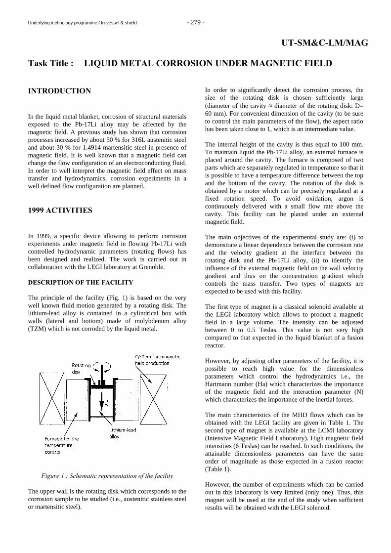
Underlying technology programme / In-vessel & shield - 279 -
UT-SM&C-LM/MAG Task Title : LIQUID METAL CORROSION UNDER MAGNETIC FIELD INTRODUCTION In the liquid metal blanket, corrosion of structural materials exposed to the Pb-17Li alloy may be affected by the magnetic field. A previous study has shown that corrosion processes increased by about 50 % for 316L austenitic steel and about 30 % for 1.4914 martensitic steel in presence of magnetic field. It is well known that a magnetic field can change the flow configuration of an electroconducting fluid. In order to well interpret the magnetic field effect on mass transfer and hydrodynamics, corrosion experiments in a well defined flow configuration are planned. 1999 ACTIVITIES In 1999, a specific device allowing to perform corrosion experiments under magnetic field in flowing Pb-17Li with controlled hydrodynamic parameters (rotating flows) has been designed and realized. The work is carried out in collaboration with the LEGI laboratory at Grenoble. DESCRIPTION OF THE FACILITY The principle of the facility (Fig. 1) is based on the very well known fluid motion generated by a rotating disk. The lithium-lead alloy is contained in a cylindrical box with walls (lateral and bottom) made of molybdenum alloy (TZM) which is not corroded by the liquid metal.
Figure 1 : Schematic representation of the facility The upper wall is the rotating disk which corresponds to the corrosion sample to be studied (i.e., austenitic stainless steel or martensitic steel).
In order to significantly detect the corrosion process, the size of the rotating disk is chosen sufficiently large (diameter of the cavity ≈ diameter of the rotating disk: D= 60 mm). For convenient dimension of the cavity (to be sure to control the main parameters of the flow), the aspect ratio has been taken close to 1, which is an intermediate value. The internal height of the cavity is thus equal to 100 mm. To maintain liquid the Pb-17Li alloy, an external furnace is placed around the cavity. The furnace is composed of two parts which are separately regulated in temperature so that it is possible to have a temperature difference between the top and the bottom of the cavity. The rotation of the disk is obtained by a motor which can be precisely regulated at a fixed rotation speed. To avoid oxidation, argon is continuously delivered with a small flow rate above the cavity. This facility can be placed under an external magnetic field. The main objectives of the experimental study are: (i) to demonstrate a linear dependence between the corrosion rate and the velocity gradient at the interface between the rotating disk and the Pb-17Li alloy, (ii) to identify the influence of the external magnetic field on the wall velocity gradient and thus on the concentration gradient which controls the mass transfer. Two types of magnets are expected to be used with this facility. The first type of magnet is a classical solenoid available at the LEGI laboratory which allows to product a magnetic field in a large volume. The intensity can be adjusted between 0 to 0.5 Teslas. This value is not very high compared to that expected in the liquid blanket of a fusion reactor. However, by adjusting other parameters of the facility, it is possible to reach high value for the dimensionless parameters which control the hydrodynamics i.e., the Hartmann number (Ha) which characterizes the importance of the magnetic field and the interaction parameter (N) which characterizes the importance of the inertial forces. The main characteristics of the MHD flows which can be obtained with the LEGI facility are given in Table 1. The second type of magnet is available at the LCMI laboratory (Intensive Magnetic Field Laboratory). High magnetic field intensities (6 Teslas) can be reached. In such conditions, the attainable dimensionless parameters can have the same order of magnitude as those expected in a fusion reactor (Table 1). However, the number of experiments which can be carried out in this laboratory is very limited (only one). Thus, this magnet will be used at the end of the study when sufficient results will be obtained with the LEGI solenoid.
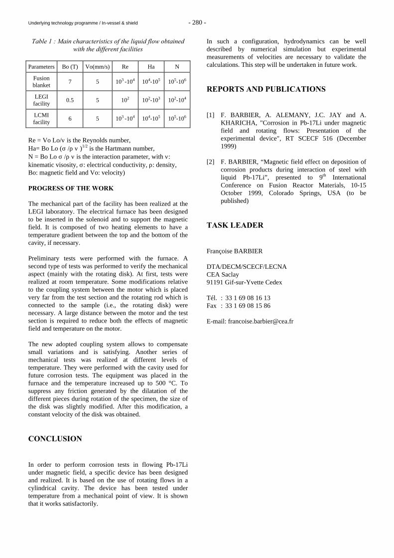
Underlying technology programme / In-vessel & shield - 280 -
Table 1 : Main characteristics of the liquid flow obtained with the different facilities
Parameters Bo (T) Vo(mm/s) Re Ha N
Fusion blanket
7 5 103 -104 104-105 105-106
LEGI facility
0.5 5 102 102-103 102-104
LCMI facility
6 5 103 -104 104-105 105-106
Re = Vo Lo/ν is the Reynolds number, Ha= Bo Lo (σ /ρ ν )1/2 is the Hartmann number, N = Bo Lo σ /ρ ν is the interaction parameter, with ν: kinematic visosity, σ: electrical conductivity, ρ: density, Bo: magnetic field and Vo: velocity) PROGRESS OF THE WORK The mechanical part of the facility has been realized at the LEGI laboratory. The electrical furnace has been designed to be inserted in the solenoid and to support the magnetic field. It is composed of two heating elements to have a temperature gradient between the top and the bottom of the cavity, if necessary. Preliminary tests were performed with the furnace. A second type of tests was performed to verify the mechanical aspect (mainly with the rotating disk). At first, tests were realized at room temperature. Some modifications relative to the coupling system between the motor which is placed very far from the test section and the rotating rod which is connected to the sample (i.e., the rotating disk) were necessary. A large distance between the motor and the test section is required to reduce both the effects of magnetic field and temperature on the motor. The new adopted coupling system allows to compensate small variations and is satisfying. Another series of mechanical tests was realized at different levels of temperature. They were performed with the cavity used for future corrosion tests. The equipment was placed in the furnace and the temperature increased up to 500 °C. To suppress any friction generated by the dilatation of the different pieces during rotation of the specimen, the size of the disk was slightly modified. After this modification, a constant velocity of the disk was obtained. CONCLUSION In order to perform corrosion tests in flowing Pb-17Li under magnetic field, a specific device has been designed and realized. It is based on the use of rotating flows in a cylindrical cavity. The device has been tested under temperature from a mechanical point of view. It is shown that it works satisfactorily.
In such a configuration, hydrodynamics can be well described by numerical simulation but experimental measurements of velocities are necessary to validate the calculations. This step will be undertaken in future work. REPORTS AND PUBLICATIONS [1] F. BARBIER, A. ALEMANY, J.C. JAY and A.
KHARICHA, "Corrosion in Pb-17Li under magnetic field and rotating flows: Presentation of the experimental device", RT SCECF 516 (December 1999)
[2] F. BARBIER, “Magnetic field effect on deposition of
corrosion products during interaction of steel with liquid Pb-17Li”, presented to 9th International Conference on Fusion Reactor Materials, 10-15 October 1999, Colorado Springs, USA (to be published)
TASK LEADER Françoise BARBIER DTA/DECM/SCECF/LECNA CEA Saclay 91191 Gif-sur-Yvette Cedex Tél. : 33 1 69 08 16 13 Fax : 33 1 69 08 15 86 E-mail: [email protected]
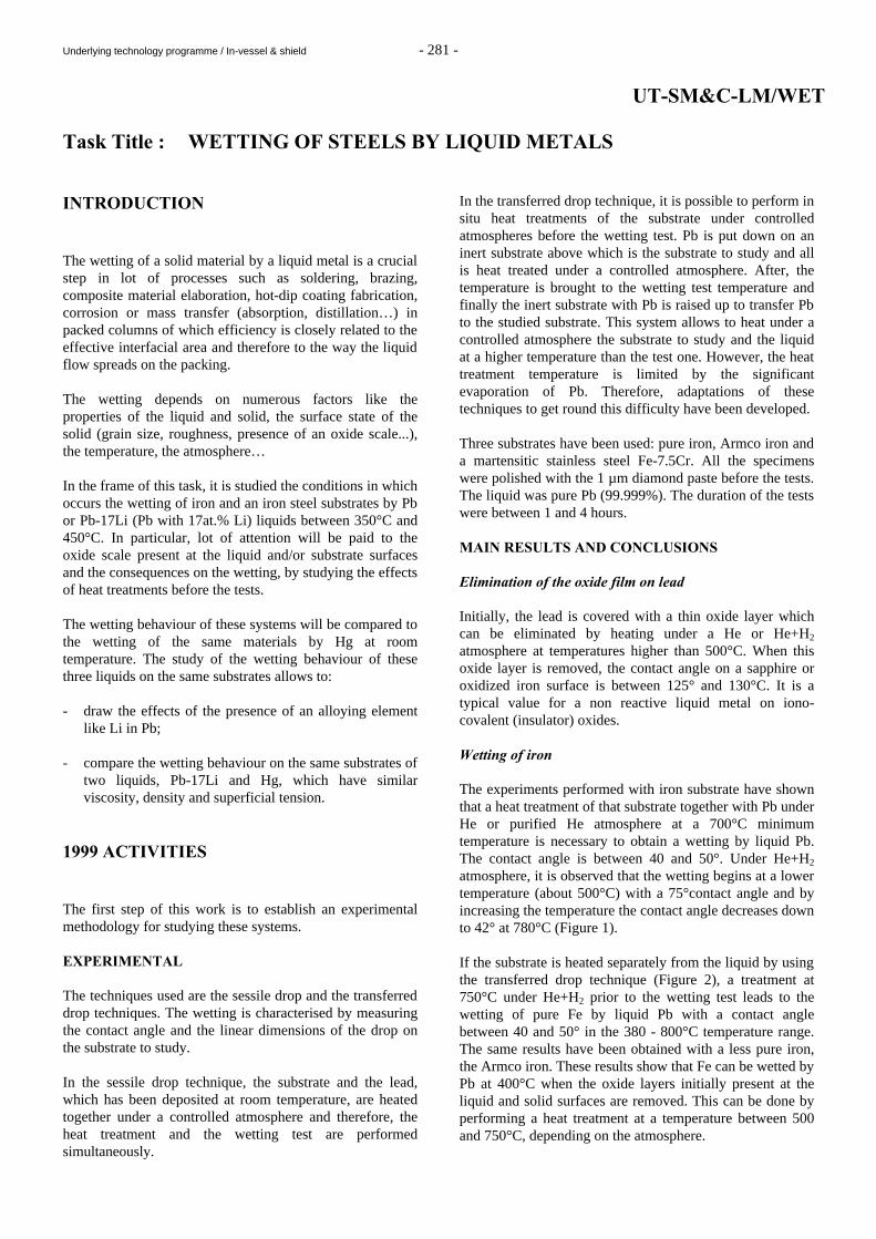
Underlying technology programme / In-vessel & shield - 281 -
UT-SM&C-LM/WET Task Title : WETTING OF STEELS BY LIQUID METALS INTRODUCTION The wetting of a solid material by a liquid metal is a crucial step in lot of processes such as soldering, brazing, composite material elaboration, hot-dip coating fabrication, corrosion or mass transfer (absorption, distillation…) in packed columns of which efficiency is closely related to the effective interfacial area and therefore to the way the liquid flow spreads on the packing. The wetting depends on numerous factors like the properties of the liquid and solid, the surface state of the solid (grain size, roughness, presence of an oxide scale...), the temperature, the atmosphere… In the frame of this task, it is studied the conditions in which occurs the wetting of iron and an iron steel substrates by Pb or Pb-17Li (Pb with 17at.% Li) liquids between 350°C and 450°C. In particular, lot of attention will be paid to the oxide scale present at the liquid and/or substrate surfaces and the consequences on the wetting, by studying the effects of heat treatments before the tests. The wetting behaviour of these systems will be compared to the wetting of the same materials by Hg at room temperature. The study of the wetting behaviour of these three liquids on the same substrates allows to: - draw the effects of the presence of an alloying element
like Li in Pb; - compare the wetting behaviour on the same substrates of
two liquids, Pb-17Li and Hg, which have similar viscosity, density and superficial tension.
1999 ACTIVITIES The first step of this work is to establish an experimental methodology for studying these systems. EXPERIMENTAL The techniques used are the sessile drop and the transferred drop techniques. The wetting is characterised by measuring the contact angle and the linear dimensions of the drop on the substrate to study. In the sessile drop technique, the substrate and the lead, which has been deposited at room temperature, are heated together under a controlled atmosphere and therefore, the heat treatment and the wetting test are performed simultaneously.
In the transferred drop technique, it is possible to perform in situ heat treatments of the substrate under controlled atmospheres before the wetting test. Pb is put down on an inert substrate above which is the substrate to study and all is heat treated under a controlled atmosphere. After, the temperature is brought to the wetting test temperature and finally the inert substrate with Pb is raised up to transfer Pb to the studied substrate. This system allows to heat under a controlled atmosphere the substrate to study and the liquid at a higher temperature than the test one. However, the heat treatment temperature is limited by the significant evaporation of Pb. Therefore, adaptations of these techniques to get round this difficulty have been developed. Three substrates have been used: pure iron, Armco iron and a martensitic stainless steel Fe-7.5Cr. All the specimens were polished with the 1 µm diamond paste before the tests. The liquid was pure Pb (99.999%). The duration of the tests were between 1 and 4 hours. MAIN RESULTS AND CONCLUSIONS Elimination of the oxide film on lead Initially, the lead is covered with a thin oxide layer which can be eliminated by heating under a He or He+H2 atmosphere at temperatures higher than 500°C. When this oxide layer is removed, the contact angle on a sapphire or oxidized iron surface is between 125° and 130°C. It is a typical value for a non reactive liquid metal on iono-covalent (insulator) oxides. Wetting of iron The experiments performed with iron substrate have shown that a heat treatment of that substrate together with Pb under He or purified He atmosphere at a 700°C minimum temperature is necessary to obtain a wetting by liquid Pb. The contact angle is between 40 and 50°. Under He+H2 atmosphere, it is observed that the wetting begins at a lower temperature (about 500°C) with a 75°contact angle and by increasing the temperature the contact angle decreases down to 42° at 780°C (Figure 1). If the substrate is heated separately from the liquid by using the transferred drop technique (Figure 2), a treatment at 750°C under He+H2 prior to the wetting test leads to the wetting of pure Fe by liquid Pb with a contact angle between 40 and 50° in the 380 - 800°C temperature range. The same results have been obtained with a less pure iron, the Armco iron. These results show that Fe can be wetted by Pb at 400°C when the oxide layers initially present at the liquid and solid surfaces are removed. This can be done by performing a heat treatment at a temperature between 500 and 750°C, depending on the atmosphere.
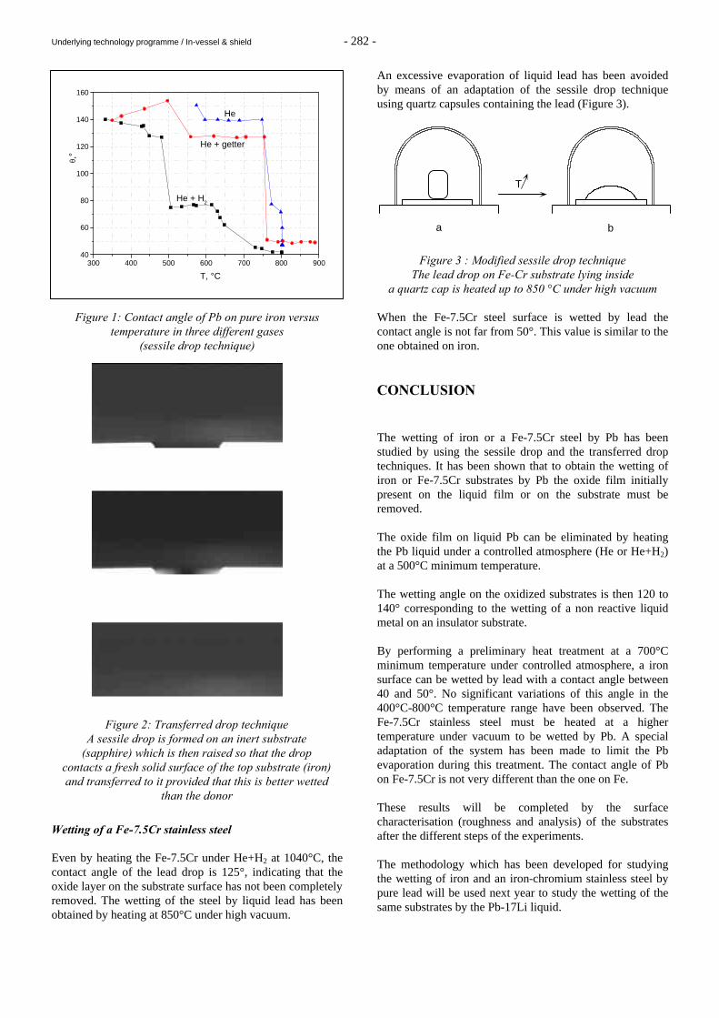
Underlying technology programme / In-vessel & shield - 282 -
Figure 1: Contact angle of Pb on pure iron versus temperature in three different gases
(sessile drop technique) Wetting of a Fe-7.5Cr stainless steel Even by heating the Fe-7.5Cr under He+H2 at 1040°C, the contact angle of the lead drop is 125°, indicating that the oxide layer on the substrate surface has not been completely removed. The wetting of the steel by liquid lead has been obtained by heating at 850°C under high vacuum.
An excessive evaporation of liquid lead has been avoided by means of an adaptation of the sessile drop technique using quartz capsules containing the lead (Figure 3).
Figure 3 : Modified sessile drop technique The lead drop on Fe-Cr substrate lying inside
a quartz cap is heated up to 850 °C under high vacuum When the Fe-7.5Cr steel surface is wetted by lead the contact angle is not far from 50°. This value is similar to the one obtained on iron. CONCLUSION The wetting of iron or a Fe-7.5Cr steel by Pb has been studied by using the sessile drop and the transferred drop techniques. It has been shown that to obtain the wetting of iron or Fe-7.5Cr substrates by Pb the oxide film initially present on the liquid film or on the substrate must be removed. The oxide film on liquid Pb can be eliminated by heating the Pb liquid under a controlled atmosphere (He or He+H2) at a 500°C minimum temperature. The wetting angle on the oxidized substrates is then 120 to 140° corresponding to the wetting of a non reactive liquid metal on an insulator substrate. By performing a preliminary heat treatment at a 700°C minimum temperature under controlled atmosphere, a iron surface can be wetted by lead with a contact angle between 40 and 50°. No significant variations of this angle in the 400°C-800°C temperature range have been observed. The Fe-7.5Cr stainless steel must be heated at a higher temperature under vacuum to be wetted by Pb. A special adaptation of the system has been made to limit the Pb evaporation during this treatment. The contact angle of Pb on Fe-7.5Cr is not very different than the one on Fe. These results will be completed by the surface characterisation (roughness and analysis) of the substrates after the different steps of the experiments. The methodology which has been developed for studying the wetting of iron and an iron-chromium stainless steel by pure lead will be used next year to study the wetting of the same substrates by the Pb-17Li liquid.
300 400 500 600 700 800 90040
60
80
100
120
140
160
He
He + getter
He + H2
T, °C
θ,°
Figure 2: Transferred drop technique A sessile drop is formed on an inert substrate
(sapphire) which is then raised so that the drop contacts a fresh solid surface of the top substrate (iron) and transferred to it provided that this is better wetted
than the donor
T
a b
Underlying technology programme / In-vessel & shield - 283 -
REPORTS AND PUBLICATIONS P. Protsenko, N. Eustathopoulos, A. Terlain Wetting of materials by liquid lead CEA Report, RT-SCECF 518 (December 1999) TASK LEADER A. TERLAIN CEREM/DECM/SCECF CEA Saclay 91191 Gif-sur-Yvette Cedex Tél. : 33 1 69 08 16 18 Fax : 33 1 69 08 15 86 E-mail : [email protected]