Fusion Splicing with Panduit Products
12
Fusion Splicing with Panduit Products Purpose The purpose of this document is to describe the advantages of field-splicing SM/MM single core &/or 12-ribbon fibers, demonstration of fusion splicing, and how using Panduit products can help. Background Splicing is a necessary field option, not only for repair, but also to enable customers to break ultra-high fiber count distribution cables down at demarcation points to route to other locations within their facilities. With the loss budget tolerances in today’s cable plants becoming tighter as the network bandwidth grows exponentially, every fraction of a dB saved can be critical to channel success. The invention of fusion splicing was to address the shortcomings of mechanical splices, specifically the time and cost savings when the two methods are compared for use with high-count-fibers. Fusion splicing provides a permament attachment of two raw fibers or 12-fiber ribbons, via an electronic arcing process in which the raw fiber endfaces are essentially melted together. This process is also completed by a sophisticated tool called a Fusion Splicer, which aids in the alignment, inspection, and curing process. Using a Fusion Splicer also lessens the factor of human error in the procedure. Technical Reference Figure 1: 12-ribbon fiber, post arc procedure.
Transcript of Fusion Splicing with Panduit Products

Fusion Splicing with Panduit ProductsPurposeThe purpose of this document is to describe the advantages of field-splicing SM/MM single core &/or 12-ribbon fibers, demonstration of fusion splicing, and how using Panduit products can help.
BackgroundSplicing is a necessary field option, not only for repair, but also to enable customers to break ultra-high fiber count distribution cables down at demarcation points to route to other locations within their facilities.With the loss budget tolerances in today’s cable plants becoming tighter as the network bandwidth grows exponentially, every fraction of a dB saved can be critical to channel success.
The invention of fusion splicing was to address the shortcomings of mechanical splices, specifically the time and cost savings when the two methods are compared for use with high-count-fibers.
Fusion splicing provides a permament attachment of two raw fibers or 12-fiber ribbons, via an electronic arcing process in which the raw fiber endfaces are essentially melted together. This process is also completed by a sophisticated tool called a Fusion Splicer, which aids in the alignment, inspection, and curing process. Using a Fusion Splicer also lessens the factor of human error in the procedure.
Technical Reference
Figure 1: 12-ribbon fiber, post arc procedure.
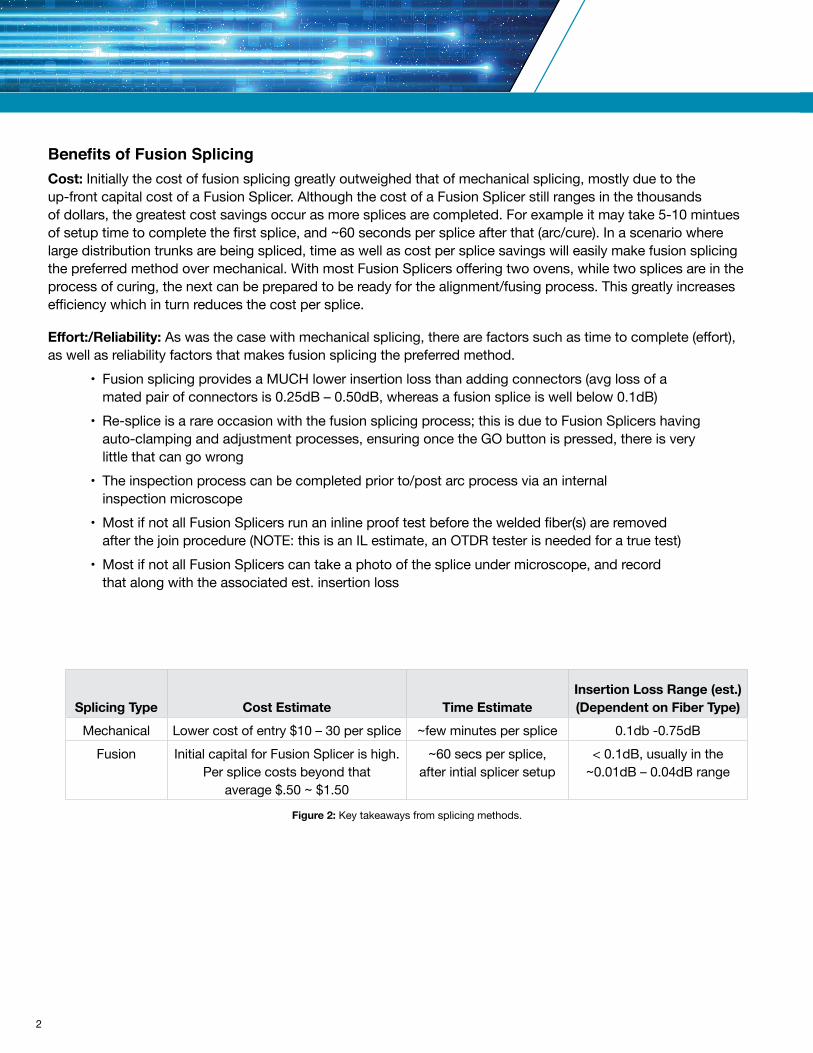
Benefits of Fusion SplicingCost: Initially the cost of fusion splicing greatly outweighed that of mechanical splicing, mostly due to the up-front capital cost of a Fusion Splicer. Although the cost of a Fusion Splicer still ranges in the thousands of dollars, the greatest cost savings occur as more splices are completed. For example it may take 5-10 mintues of setup time to complete the first splice, and ~60 seconds per splice after that (arc/cure). In a scenario where large distribution trunks are being spliced, time as well as cost per splice savings will easily make fusion splicing the preferred method over mechanical. With most Fusion Splicers offering two ovens, while two splices are in the process of curing, the next can be prepared to be ready for the alignment/fusing process. This greatly increases efficiency which in turn reduces the cost per splice.
Effort:/Reliability: As was the case with mechanical splicing, there are factors such as time to complete (effort), as well as reliability factors that makes fusion splicing the preferred method. • Fusion splicing provides a MUCH lower insertion loss than adding connectors (avg loss of a mated pair of connectors is 0.25dB – 0.50dB, whereas a fusion splice is well below 0.1dB) • Re-splice is a rare occasion with the fusion splicing process; this is due to Fusion Splicers having auto-clamping and adjustment processes, ensuring once the GO button is pressed, there is very little that can go wrong • The inspection process can be completed prior to/post arc process via an internal inspection microscope • Most if not all Fusion Splicers run an inline proof test before the welded fiber(s) are removed after the join procedure (NOTE: this is an IL estimate, an OTDR tester is needed for a true test) • Most if not all Fusion Splicers can take a photo of the splice under microscope, and record that along with the associated est. insertion loss
Figure 2: Key takeaways from splicing methods.
Splicing Type Cost Estimate Time EstimateInsertion Loss Range (est.)(Dependent on Fiber Type)
Mechanical Lower cost of entry $10 – 30 per splice ~few minutes per splice 0.1db -0.75dBFusion Initial capital for Fusion Splicer is high.
Per splice costs beyond that average $.50 ~ $1.50
~60 secs per splice, after intial splicer setup
< 0.1dB, usually in the ~0.01dB – 0.04dB range
2
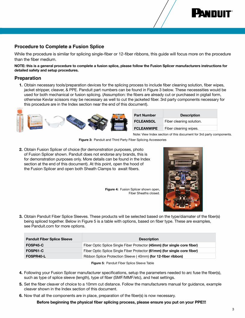
Preparation 1. Obtain necessary tools/preparation devices for the splicing process to include fiber cleaning solution, fiber wipes, jacket stripper, cleaver, & PPE. Panduit part numbers can be found in Figure 3 below. These necesssities would be used for both mechanical or fusion splicing. (Assumption: the fibers are already cut or purchased in pigtail form, otherwise Kevlar scissors may be necessary as well to cut the jacketed fiber. 3rd party components necessary for this procedure are in the Index section near the end of this document).
2. Obtain Fusion Splicer of choice (for demonstration purposes, photo of Fusion Splicer shown. Panduit does not endorse any brands, this is for demonstration purposes only. More details can be found in the Index section at the end of this document). At this point, open the hood of the Fusion Splicer and open both Sheath Clamps to await fibers.
Procedure to Complete a Fusion SpliceWhile the procedure is similar for splicing single-fiber or 12-fiber ribbons, this guide will focus more on the procedure than the fiber medium. NOTE: this is a general procedure to complete a fusion splice, please follow the Fusion Splicer manufacturers instructions for detailed safety and setup procedures.
Figure 3: Panduit and Third Party Fiber Splicing Accessories
Part Number DescriptionFCLEANSOL Fiber cleaning solution.
FCLEANWIPE Fiber cleaning wipes.Note: View Index section of this document for 3rd party components.
4. Following your Fusion Splicer manufacturer specifications, setup the parameters needed to arc fuse the fiber(s), such as type of splice sleeve (length), type of fiber (SMF/MMF/etc), and heat settings. 5. Set the fiber cleaver of choice to a 10mm cut distance. Follow the manufacturers manual for guidance, example cleaver shown in the Index section of this document. 6. Now that all the components are in place, preparation of the fiber(s) is now necessary. Before beginning the physical fiber splicing process, please ensure you put on your PPE!!!
Figure 5: Panduit Fiber Splice Sleeve Table
3. Obtain Panduit Fiber Splice Sleeves. These products will be selected based on the type/diamater of the fiber(s) being spliced together. Below in Figure 5 is a table with options, based on fiber type. These are examples, see Panduit.com for more options.
Panduit Fiber Splice Sleeve DescriptionFOSP45-C Fiber Optic Splice Single Fiber Protector (45mm) (for single core fiber)FOSP61-C Fiber Optic Splice Single Fiber Protector (61mm) (for single core fiber)FOSPR40-L Ribbon Splice Protection Sleeve ( 40mm) (for 12-fiber ribbon)
Figure 4: Fusion Splicer shown open, Fiber Sheaths closed.
3

Fiber PreparationThis guide is demonstrating 12-fiber ribbon splicing. While the process is similar for single-fiber, different tools and Fusion Splicers may be necessary. 7. Slide one of the Panduit Splice Sleeves over the jacketed fiber, and let it rest a few inches beyond the end of the fiber to be cleaved/spliced. This is to ensure once the fiber has been stripped and cleaned, it will not be touched again. This process is only necessary on one of the fibers. The second fiber, once fused, will be in the other end of the sleeve once the arc process has been completed.
8. Using the jacket stripper, complete the stripping of the fiber(s) protective coating, following manufacturer specifications, until the bare fiber(s) are exposed on the ends of each of the fiber(s) to be spliced. More information about the jacket stripper can be found in the Index section near the end of this document
9. To ensure there is no particulate or finger oils on the bare fiber(s) after jacket removal, take a fiber wipe, add a bit of the cleaning solution to. Gently wrap the wipe around the bare fibers and pull it through the wipe towards your body. Complete this a few times to ensure any foreign matter is removed from the bare fiber(s). In the event the bare fiber breaks, start the process again by stripping more jacket back following Step 8 and repeating the cleaning process. Do this for each end of the bare fiber(s) you are wishing to splice.
10. Once it is determined the bare fiber(s) are clean, the next step is cleaving. (Inspection of the fiber(s) can be completed via the Fusion Splicer, which is why an external microscope is not required here).
Figure 6: Pulling a splice sleeve over ribbon fibers, prior to cleave/splice.
Figure 7: Removing the jacket from the fiber.
Figure 8: Example method of cleaning the bare fiber(s).
4

Fiber CleavingComplete this procedure for each fiber(s), one at a time. 11. Once the fiber has been given a thorough cleaning as completed in Step 9, ensure not to touch the bare fiber throughout the rest of this procedure. 12. Place the recently cleaned bare fiber(s) end into the ribbon fiber cleaver. See the Index at the end of this document for more info on the cleaver. Cleave to an approximate depth of 10mm (follow the Fusion Splicer manufacturers instructions for cleave length).
Figure 9: Cleaving the bare fiber(s).
13. After the bare fiber(s) has been cleaved, carefully snap it into place in the awaiting Fusion Splicer. Clamp down the Sheath Clamps to secure the fiber in place as shown in Figure 10. Ensure the bare fiber doesn’t reach past the electrode, as is shown by the red arrows in Figure 11.
14. Return to Step 7 of this guide to repeat the process for the second fiber to be spliced. After the strip, clean, cleave, insertion into the Fusion Splicer has been completed, the next step is starting the Fusion Splice procedure. (Note: the second fiber does not need an additional splice sleeve.)
Figure 10: Inserting the bare fiber(s) into the Fusion Splicer. Sheath Clamp shown on the left.
Figure 11: Bare fiber sections loeaded into Splicer.
5

Fusion SplicingAs previously mentioned, most Fusion Splice systems have an automatic core-alignment system, and lenses/cameras on the X & Y axis’s to provide the least amount of offset and reflection, and thereby minimizing insertion loss. 15. To begin the physical fusion splice now that both fiber(s) have been secured into place in the Fusion Splicer, close the hood of the Splicing unit.
Figure 12: Image after the Start/Go button being pressed on the Fusion Splicer.
16. Once the hood is closed, there will be a ‘Go’ or ‘Start’ button available on the LCD screen (specific to the model demonstrated here), which will auto-align the separated fiber cores. Next up is a ‘prefusion check’ which heats the cores to ensure they can reach optimum temperature for fusion, and once completed, the arc-fusion process. (This is an automated procedure, only listed out for instructional purposes). After this completes in ~15 seconds, the LCD will display an ESTIMATED Insertion Loss, in this case, 0.02dB, and at this point the fiber(s) have been electrically fused. NOTE: If there is an issue with the prefusion check, the Fusion Splicer will display a message that something needs to be attended to before you can continue.
17. This completes the process to fuse or weld the fiber(s) to become one continuous ribbon fiber.
Figure 13: Image of completed arc process on the LCD screen. Figure 14: Image of completed arc process, fibers fused.
6

Post-Fusion Heat and ShrinkOnce the two fibers have been ‘welded’ together with the fusion process, there still needs to be a level of protection added to the new joint. The splicing sleeve heating/shrinking process will essentially heat the epoxy to form a protective barrier around the joint. In addition to a level of protection, when the splicing sleeve with integral steel strengthening member is heated around in the joint in the oven, it will solidify around the joint to greatly increase the tensile strength of the newly welded fiber(s). 18. Ensure that the timer or light signifying the completion of the arc process is completed before starting this step! Reminder: Do not touch the bare fiber or lay it down as it may pick up dust/oils during this process. 19. Unclasp the hood of the Fusion Splicer to expose the recently fused fiber(s). 20. Next ensure that one of the heating ovens on the Splicer is open and ready to receive the newly joined fiber(s). 21. Once an oven is open, unclasp the sheath clamps on the fusion chamber that were securing the fiber(s) in place during the fusion procedure.
22. Use caution when handling this fiber as the joint is still unprotected at this point. Prior to picking the joined fiber(s) up, slide the splicing sleeve as close to the fusion chamber clasp as is possible. This will make it easier to slide it over the fused joint once you lift the fiber from the chamber. Shown to the left of the Fiber Sheath in Figure 15 above. 23. Lift the fiber from the fusion chamber, and CAREFULLY slide the splicing sleeve over the joint, ensuring the joint is as close to the middle point of the sleeve as is possible. This will ensure the greatest tensile strength and joint protection post-curing process. 24. At this point, lay the fiber into the curing oven portion of the Fusion Splicer, ensuring that 1) the splice sleeve is as centered as possible over the joint, and 2) that the fiber, with splice sleeve covering it, is as centered in the oven chamber as possible to ensure even heating throughout the curing process.
Figure 15: Sheath Clamps shown, red arrows.
Figure 16: Spliced Fiber with splicing sleeve in place, being laid into Oven 1.
7

25. Most Fusion Splicer ovens will have an auto-clamping process, making it easy to push the fiber down at latch points, and it will grab and seat the sleeved fiber for curing. After the fiber has been clamped into place, visually ensure the oven cover has closed. Note: if fiber was not secured into the middle of the oven enclousure, unclamp and complete this again. Also some Fusion Splicers require the fusion chamber hood to be closed at this point, close the hood here if necessary. 26. Find the power button associated with the oven that the joined fiber is now in. Push the start button and it will take approximately ~35 – 45 seconds to heat and shrink the split sleeve/epoxy to the joined fiber. 27. Once there is audible or visual indication of completion (dependent on Fusion Splicer model), push down on the clasps to remove the completed fusion splice (Figure 17). Caution: the splice sleeve will still be HOT, do not touch!
28. After it’s removed from the oven, the heated sleeve will need a few moments to cool down. Lay the joined fiber into one of available cooling trays, as noted by the red arrows in Figure 18. It’s a good idea to not touch them until they have fully come to room temperature, which is about the time it would take for any additional splices to be completed.
29. This completes the fusion splice process.
NOTE: There are published procedures for link channel warranty testing with approved testers available on Panduit.com. Tier 1 or Tier 2 link testing is outside the scope of this document.
Figure 17: View of oven clasps.
Figure 18: View of dual cooling trays.
8

https://www.panduit.com/en/products/fiber-optic-systems/fiber-optic-panels-cassettes-enclosures/fiber-optic-enclosures/fwmhssgs-3456.html
SummaryThe process of fusion splicing is critical in today’s enterprise and data center environments. With manufacturers releasing high fiber count cables with fiber counts in excess of 6,912 fibers, installers only option to distribute these large fiber counts to multiple demarcation points is via splicing. As it was clearly shown, fusion splicing provides the greatest return for both cost per splice, as well as ultimately the lowest reflectivity and insertion loss (IL), which is critical in high bandwidth, low latency applications.
How Else Can Panduit Help?While Panduit does not build Fusion Splicers, nor recommends any particular brand, we do offer many products that are used with fusion splicing. Panduit manufactures Fiber Patch Cord Pigtails, Fiber Trunk Pigtails (blunts), Splice Trays, and Enclosures both for a few dozen fibers all the way up to 6,912 fibers.
Fiber Enclosures
Opticom® Enclosures ● 1 – 4 RU, ranges from 72 – 288 fibers per enclosure
HD Fusion Fiber Splicing Enclosure ● 4 RU, the HD Fusion enclosure can handle up to 576 single fiber cables and 864 ribbon fiber cables
HD Flex™ Wall Mount Hyperscale Enclosures ● Can handle up to 3,456 ribbon fibers (also available in a 6,912-ribbon fiber model)
Part Number DescriptionFRME1U 1 RU rack mount enclosure, (72 fibers).FRME2U 2 RU rack mount enclosure, (144 fibers).FRME3 3 RU rack mount enclosure, (216 fibers).FRME4 4 RU rack mount enclosure, (288 fibers).
Part Number DescriptionFRMHSS-4RU Houses up to 576 single fiber cables, 864 ribbon fiber cables.
Part Number DescriptionFWMHSSGS-3456 Fiber wall mount hyperscale splice enclosure for up to 3,456
ribbon fibers.FWMHSSGS-6912 Fiber wall mount hyperscale splice enclosure for up to 6,912
ribbon fibers.
https://www.panduit.com/content/dam/panduit/en/products/media/2/22/322/5322/101375322.pdf
https://www.panduit.com/en/products/fiber-optic-systems/fiber-optic-panels-cassettes-enclosures/fiber-optic-enclosure-accessories/frmhss-4ru.html
9

10
Fiber Enclosure Accessories
Opticom® Fiber Optic Splice Module
HD Fusion
https://www.panduit.com/en/products/fiber-optic-systems/fiber-optic-panels-cassettes-enclosures/fiber-optic-enclosure-accessories/fhdbrkout17.html
https://www.panduit.com/en/products/fiber-optic-systems/fiber-optic-panels-cassettes-enclosures/fiber-optic-enclosure-accessories/fst144r.html
https://www.panduit.com/en/products/fiber-optic-systems/fiber-optic-panels-cassettes-enclosures/fiber-optic-enclosure-accessories/fhdbrkout28.html
Part Number DescriptionFOSMF Fiber optic splice module that protects up to 24 fusion splices.
Part Number DescriptionFST48 Fiber splice tray kit for up to (48) single-core-fiber
fusion splices.
Part Number DescriptionFHDBRKOUT17 High fiber count cable breakout kit, cables w/OD
between 9mm – 17mm.
Part Number DescriptionFST144R Fiber splice tray kit for up to (144) ribbon fusion splices.
Part Number DescriptionFHDBRKOUT28 High fiber count cable breakout kit, cables w/OD
between 16mm – 28mm.
https://www.panduit.com/en/products/fiber-optic-systems/fiber-optic-panels-cassettes-enclosures/fiber-optic-enclosure-accessories/fst48.html
https://www.panduit.com/content/dam/panduit/en/products/media/5/25/925/8925/18925.pdf
(Breakout cover omitted for clarity.)
(Breakout cover omitted for clarity.)
https://www.panduit.com/content/dam/panduit/en/products/media/6/16/116/3116/106663116.pdf
Part Number DescriptionFLEX1U06 HD Flex™ 1 U enclosure (12 ind. cassettes).FLEX2U06 HD Flex™ 2 U enclosure (24 ind. cassettes).FLEX4U06 HD Flex™ 4 U enclosure (48 ind. cassettes).
(FLEX2U06 image shown). HD Flex™ Enclosures can handle up to 144 LC fiber cables. and 576 MPO ribbon fiber cables per RU.
HD Flex™

11
Fiber MediaFor assistance with further media or high-fiber-count distribution cables, please contact [email protected] for support. LC Pigtail
Opticom® Splice Cassettes
Bulk Fiber Cable (2 – 144 Fibers)
Part Number DescriptionFZ1BN1NNNSNM001 OM4 1-fiber 900μm buffered patchcord no jacket LC to pigtail Std IL – 1 meter.
Part Number DescriptionFCS9N-12-10R OS2 12-fiber ribbonized pigtail; Standard IL.
Part Number Region DescriptionFSNP948Y Americas 900μm OS2 48-fiber indoor-outdoor stranded tube cable,
plenum (OFNP), 250μm fibers.FLNL948Y Asia Pacific 900μm OS2 48-fiber indoor-outdoor stranded tube cable,
LSZH, 250μm fibers.FANC948-24 EMEA 900μm OS2 48-fibre indoor-outdoor stranded tube cable,
EuroClass Cca-s1a-d1-a1, 250μm fibres.
Link to part selector https://www.panduit.com/content/dam/panduit/en/products/media/4/54/554/8554/109908554.pdf
Link to part selector https://www.panduit.com/content/dam/panduit/en/products/media/9/69/569/0569/109870569.pdf
Link to part selector https://www.panduit.com/content/dam/panduit/en/products/media/9/69/569/0569/109870569.pdf
Example part number, use chart below for selection.
MPO Pigtail
Part Number DescriptionFZTCN7NNNONM001 OM4 MPO ribbon pigtail assembly.
Link to part selector https://www.panduit.com/content/dam/panduit/en/products/media/8/18/018/9018/109869018.pdf
Example part number, use chart below for selection.
HD Flex™ Splice Cassettes
Part Number DescriptionFHS9N-12-10R OS2 12-fiber ribbonized pigtail; Standard IL.
Link to part selector https://www.panduit.com/content/dam/panduit/en/products/media/2/72/272/7272/106587272.pdf
Example part number, use chart below for selection.
Example part number, use chart below for selection.
Example part number, use chart below for selection.
Bulk Ribbon Fiber Cable (144 – 288 Fibers) *additional ribbon cable counts coming soon*
Part Number Region DescriptionFFDPAX144F Americas OS2 144-fiber indoor distribution cable, plenum (OFNP),
flexible ribbon, FT.FFCDBX288-28M All Regions OS2 288-fiber indoor-outdoor cable, OFNR-LSZH CPR
Cca-s1a-d0-a1 flexible ribbon, MT.
Example part number, contact Customer Service for assistance.
©2020 Panduit Corp. ALL RIGHTS RESERVED. FBAG05--SA-ENG 11/2020
Panduit DifferencePanduit is committed to delivering a consistently high level of quality and service the world over. With a presence in more than 100 countries, local Panduit sales representatives and technical specialists offer guidance and support that bring value to your business. Our global supply chain, which includes manufacturing, customer service, logistics, and distribution partners, provides prompt response to your inquiries and streamlines delivery to any worldwide destination.
THE INFORMATION CONTAINED IN THIS APPLICATION GUIDE IS INTENDED AS A GUIDE FOR USE BY PERSONS HAVING TECHNICAL SKILL AT THEIR OWN DISCRETION AND RISK. BEFORE USING ANY PANDUIT PRODUCT, THE BUYER MUST
DETERMINE THE SUITABILITY OF THE PRODUCT FOR HIS/HER INTENDED USE AND BUYER ASSUMES ALL RISK AND LIABILITY WHATSOEVER IN CONNECTION THEREWITH. PANDUIT DISCLAIMS ANY LIABILITY ARISING FROM ANY INFORMATION
CONTAINED HEREIN OR FOR ABSENCE OF THE SAME.
www.panduit.com
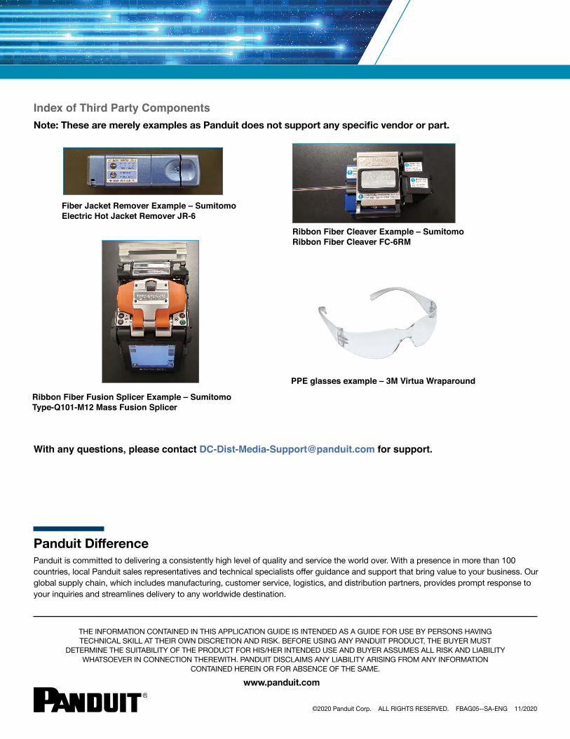
Index of Third Party ComponentsNote: These are merely examples as Panduit does not support any specific vendor or part.
Ribbon Fiber Cleaver Example – Sumitomo Ribbon Fiber Cleaver FC-6RM
Ribbon Fiber Fusion Splicer Example – Sumitomo Type-Q101-M12 Mass Fusion Splicer
Fiber Jacket Remover Example – Sumitomo Electric Hot Jacket Remover JR-6
PPE glasses example – 3M Virtua Wraparound
With any questions, please contact [email protected] for support.