FUSION SERIES - Syringe Pump Manufacturer | Chemyx Inc · A syringe pump is a small,...
57
FUSION SERIES USER MANUAL
Transcript of FUSION SERIES - Syringe Pump Manufacturer | Chemyx Inc · A syringe pump is a small,...

FUSION SERIESUSER MANUAL

2
EU Declaration of Conformity (DoC) 6
Manual Description 7
General Information 7
Safety Information 7
Warranty and Repair Information 9
Limited Warranty 9
Repair Facilities and Parts 9
Dead Pixel Policy 8
Serial Numbers 8
Calibrations 8
Product Overview 9
The Fusion Series Syringe Pumps 9
Principle of Operation 9
Features 11
Pump 11
Controls 14
Power and Data Connectors 15
Audible Alerts 15
Stall Detection 15
Specifications 16
Pump Setup 17
PoweringOn/OffthePump 17
Loading a Syringe 18
Fusion 100 18
Fusion 200 19
Fusion 400 20

3
Adjusting the Safety Collar 20
Fusion 100 and 200 21
Fusion 400 21
Pump Operation 22
Selecting Items 22
Navigating Between Screens 23
Entering Values 23
Entering Numbers 23
Entering Letters 23
Mode Selection Screen 24
Basic Mode 24
Syringe Selection 25
Target Transfer Volume 26
Infusion/Withdrawal (Fusion 200 only) 26
Flow Rate 27
Start-Time Delay 27
Options 28
Flow-Rate Units 28
Saving Run Parameters 29
Priming/Bolus Rate 29
Enable Volume Lock 30
Multi-Step Mode 31
Setup 31
Syringe Selection 31
Total Steps 31
Loop All 32

4
Sub-Loops 32
Flow-Rate Units 33
Step Parameters 33
Target Transfer Volume 33
Infusion/Withdrawal (Fusion 200 only) 34
Flow Rate 34
Static Flow Rate 35
Variable Flow Rate 35
Start-Time Delay 35
Step Loop 36
Running the Pump 37
Basic Mode System Status 38
Multi-Step Mode System Status 39
System Load Run 42
System Settings 43
Touchscreen Toggle 43
Baud Rate 43
Power Settings 44
Motor Power` 44
LCDPower-OffTime 44
Pump Control by Computer 46
Cable Requirements 46
Connecting 47
Settings 47
Pump Commands 47
Chemyx Pump Controller Programs 54

5
Pump Maintenance 54
Lubricating the Pump 54
Replacing the Fuse 56
Pump Accessories 57
Foot Switch 57
Connecting the Foot Switch 57
Using the Foot Switch 57
10-Channel Syringe Rack (Fusion 200 only) 58
Attaching the Rack 59
Loading Syringes 61
Appendices 62
Appendix A: Syringe Volume/Diameter Reference Table 62
Appendix B: Available Parts 56
Fusion Series Syringe Pumps 56
Options and Accessories 56
Stainless-Steel Syringes 56
Appendix C: Contact Information 57
INTELLECTUAL PROPERTYAllIntellectualProperties,asdefinedbelow,ownedbyorwhichisotherwisethepropertyofChemyxInc.oritssuppliersrelatingtotheChemyxsyringepumps,includingbutnotlimitedto,accessories,
partsorsoftwarerelatingthereto(ChemyxSyringePumps),areproprietarytofederalandstatelaws,andinternationaltreatyprovisions.IntellectualPropertyincludesbutisnotlimitedto,inventions
(patentableorunpatentable),patents,tradesecrets,copyrights,software,firmware,computerprograms,andrelateddocumentationandotherworksofauthorship.Moreover,youagreethatyouwill
not, and will not attempt to, modify, prepare derivative works of, reverse engineer, disassemble the Chemyx syringe pumps, decompile or otherwise attempt to create source code from the related
software/firmware.NotitletoorownershipinIntellectualPropertyistransferredtoyou.AllapplicablerightsoftheIntellectualPropertyshallremainwithChemyxanditssuppliers.

6
Declaration of Conformity
ThePDFversionofthelatestDoCcanbedownloadedatwww.chemyx.com/support

7
General Description
PleasereadthefollowingsafetyprecautionstoensurepersonalsafetyandoperationallongevityoftheChemyxsyringepump.Chemyx is not responsible for the equipment if used in amanner not specified by themanufacturer; warranty coverageprovidedbytheequipmentmaybedroppedasaresult.
CHEMYX PRODUCTS ARE NOT APPROVED FOR CLINICAL USE ON HUMANS.
Chemyx isnotresponsible for theuseofpowersuppliesoutsidethestatedelectricalspecificationsor failuretoswitchthepowerconverterfrom220Vto110Vwhileinthe220Venvironmentorviceversa.
Theproductshouldbeproperlygrounded.
Use Proper Power Supply
Ground Product
Safety Information
WarrantycoveragewillbelostifthepumpisopenedwithoutauthorizationfromChemyx.Donottouchanyelectricalconnectorsonorintheproduct.
Even though the pump can operate at extremely fast speeds, the user must determine the properflowrateforanygivenapplication.Forinstances,pumpingat90mL/minusinga20-gaugeneedlewillcausestallsand/orpotentialburstingofthesyringe.Chemyxisnotresponsibleforanydamagethatmightresultfromsituationssimilartotheexampleabove.
Do Not Open The Pump
Do Not Operate With Suspected Failures

8
Donotplacefingersbetweenthepusherblockandtheendblockwhilethepumpisrunning.
Readalllabelsontheproducttoensureproperusage.
The user is responsible for wetting ground glass syringes and setting and tightening the safety collar/barappropriately.
Pinch Hazard
Observe all Warning labels on Product
Chemyx is not Responsible for Syringe Damage

9
Warranty and Repair Information
Chemyxprovidesatwo-yearwarrantyfromtheshipmentdateforitspumpsagainstdefectsinmaterialsandworkmanship.Chemyxwillrepairanyproductthatprovesdefectiveduringitsstatedwarrantyperiod.
The foregoing warranty will not apply to damage resulting from:
You must contact Chemyx (call +1 281-277-5499 or visit www.chemyx.com/contact-us)beforereturningaproduct.ChemyxwillissueaReturnAuthorization(RA)numbertoyou.
Return products to:
ChemyxInc.
10905CashRoad|Stafford,TX77477USA.
Warranty Information
Improperorinadequatemaintenanceoroperation.
Unauthorizedmodificationormisuseoftheproduct.
Operationoutsidetheelectricalspecificationsfortheproduct.
Operationoutsidethetemperaturespecificationsfortheproduct.
User-inducedinternalandexternalcontaminationsoftheinstrument.
Failuretousepropersurgeprotection.
Improper product return, packaging, and shipping
Removing serial number from syringe pump

10
Chemyxcanrepairanysyringepumpwithoutmajordamage.YoumustcontactChemyx(call+1281-277-5499orvisitusatwww.chemyx.com/contact-us)beforeshippingaproductforrepair.ChemyxwillissueaReturnAuthorization(RA)numbertoyou.
Return products to:
Chemyx Returns
10905CashRoad|Stafford,TX77477USA
DuringtheLCDMonitormanufacturingprocess,itisnotuncommonforoneormorepixelstobecomefixedinanunchangingstate.Thevisibleresultisafixedpixelthatappearsasanextremelytiny,darkorbrightdot.Inalmosteverycase,thesefixedpixelsarehardtoseeanddonotdetractfromdisplayqualityorusability.Adisplaywiththreetosevenbrightordarkdotsisconsiderednormalandwithinindustrystandards.Ifyourscreendisplaysmorethansevendeadpixelsduringthewarrantyperiod,yoursystemwillqualifyforwarrantyreplacement.PleaseseetheLimitedWarrantysectionfordetailsonhowtoactivateawarrantyclaim.
Theserialnumberislocatedontheback,topleftcornerorcenterofthepumpunderasmallbarcode.Removaloftheserialnumberlabelwillvoidthewarranty.
Chemyxpumpsarepre-calibrateduponarrivaltoyoursite.Allcalibratedparametersarewithinstatedaccuracyandprecisionspecifications of the pump. Although the pump is highly accurate, syringes of differentmaterials can attribute significantvolumeerrors.Typically,theseerrorscanrangefrom1%forglasssyringesto5%forplasticsyringes.Chemyxisnotresponsibleforerrorsgeneratedfromsyringes.
Repair Facilities and Parts
Dead Pixel Policy
Serial Numbers
Calibrations

11
Product Overview
ChemyxFusionSeriessyringepumpsaredesignedtohandleeverytypeofhigh-precisiondosingapplication.Theunits’flexibilitywith syringe types and sizes and an advanced software interface make this line of high-precision syringe pumps integrable intoanyoperationorlaboratoryworkflow.Thoroughlydurablebothinsideandout,theChemyxFusionsyringepumpsaredesignedtoprovideyearsofconstantandreliableservice.
Asyringepumpisasmall,positive-displacementpumpusedtograduallytransferprecisevolumesoffluid.AllChemyxFusion-seriessyringepumpsaredrivenviaasteppermotor.Thissteppermotorpreciselyturnsaleadscrewthatisthreadedthroughapusherblock,whichcausesthepusherblocktomove.Whenthepumpisininfusionmode,thepusherblockpushesagainsttheplungerofasecuredsyringe,causingthefluidtobeejectedatanaccurateandpreciserate.
Ifthepumpiscapableofwithdrawal,theplungerofthesyringeisheldbybracketsonthepusherblock.Whenthesteppermotorturnsintheoppositedirection,thepusherblockmovessuchthatthesyringeplungerispulled,thusdrawingfluidintothesyringe.
FortheFusionSeriessyringepumps,thepusherblockmovestotherightforinfusionandtotheleftforwithdrawal.
Principle of Operation

12+1281-277-5499|www.chemyx.com
AllFusionSeriespumpshaveasingleleadscrewthroughwhichthepusherblockisthreaded.Thepusherblockmoveswhentheleadscrewturns.Thetwoguiderodskeepthepusherblockhorizontalandperfectlyperpendiculartotheleadscrew.Theblock-release button disengages the pusher block from the lead screw, which allows the pusher block to be easily moved to a newpositionaslongasthebuttonisheld.Releasingthebuttonwilllockthepusherblockbackinplace.
Syringesareplacedonthesyringe-holderblockinthev-shapedgrooves,orchannels,andheldsecurelyusingsyringeclamps.TheFusion100and200bothhavetwosyringechannels,whiletheFusion400hasfoursmallersyringechannels.
The safety collar of the Fusion 100 and 200 helps protect the integrity of syringes by keeping the pusher block from pushing onacompletelydepressedsyringe.
Controlled Elements
Block Release Button Syringe Holder BlockSafety Collar
Lead Screw Guide Rods Pusher Block Syringe Clamp Syringe Channels
Fusion 100 pump components

13+1281-277-5499|www.chemyx.com
TheFusionSeriesusesabright,4.25”,resistive,LCDtouchscreenwithanintuitivegraphicaluserinterface(GUI)forsettingupdetailedpumprunmethods.ButtonsandentryfieldswithintheGUIareallselectableusingthetouchscreen.Asaresistive,LCDtouchscreen,theinterfacecanbeoperatedwithanyobject,notjustthetouchofafingertip.Selectingelementsbytouchonlyrequiresasmallamountofpressure;however,pleasedonotusesharpobjectsastheymaydamagethescreen.
The Fusion series also includes physical navigation controls, allowing users to manually maneuver between selectable GUI elementswithouttouchingthescreen.InputtingnumbersandletterswithintheGUIisdoneusingthephysicalnumerickeypad.Thephysicalpumpcontrolkeysareusedtostart,pause,andstoppumpactivity.
The power LED and pump-control LEDs allow users to easily discern whether the pump is on and whether it is currently running, paused,orstopped.
Navigation Keypad
Front Panel of Pump
Controls
Power LED Pump Controls LCD Touchscreen Numeric Keypad

14+1281-277-5499|www.chemyx.com
In addition to having all of the same features and components of the Fusion 100, the Fusion 200 is capable of both infusion andwithdrawal.Becauseof thisdifference, theFusion200uses adjustable retaining brackets on the pusher block and the syringe-holder block that keep the syringe in place during bothinfusionandwithdrawal.
In addition to having all of the same features and components of the Fusion 100, the Fusion 200 is capable of both infusion andwithdrawal. Because of this difference, the Fusion 200uses adjustable retaining brackets on the pusher block and the syringe-holder block that keep the syringe in place during bothinfusionandwithdrawal.
Bracket Release Knob
Bracket Release Knob
Flange Retaining Bracket
Flange Retaining Bracket
Plunger Retaining Bracket
Plunger Retaining Bracket
Bracket Release Knob
Bracket Release Knob
Fusion 200 Specific Components
Fusion 400 Specific Components

15
Specifications
Specification Fusion 100 Fusion 200 Fusion 400
Movement Modes Infusion Infusion/
Withdrawal Infusion
Syringe Sizes W(Min/Max) 0.5μL/60mL 0.5μL/60mL 0.5μL/10mL
Flow Rate Range (Smallest Syringe)
0.0001to1.5679μL/min
0.0001to1.5679μL/min
2 to 10.536pL/min
Flow Rate Range (Largest Syringe)
0.0002mL/minto 128 mL/min
0.0002mL/minto 128 mL/min
4.83pL/minto2.1mL/min
Drive Mecha-nism
1.8°steppermotorwith1/32 microstepping
1.8°steppermotorwith1/32 microstepping
1.8°steppermotorwith1/32 microstepping
Step Resolution 0.098μm/μstep 0.046μm/μstep 0.016μm/μstep
Nominal Linear Force 16 kg (35 lbs) 23 kg (50 lbs) 23 kg (50 lbs)
Accuracy ±<0.04%error(99.96%) ±<0.04%error(99.96%) ±<0.04%error(99.96%)
Reproducibility ±<0.05%deviation(99.95%) ±<0.05%deviation(99.95%) ±<0.05%deviation(99.95%)
Operation Temp 4°Cto40°C(40°Fto104°F)
4°Cto40°C(40°Fto104°F)
4°Cto40°C(40°Fto104°F)
Storage Temp -10°Cto70°C(14°Fto158°F)
-10°Cto70°C(14°Fto158°F)
-10°Cto70°C(14°Fto158°F)

16
Specifications (Continued)
Specification Fusion 100 Fusion 200 Fusion 400
Relative Humidity 20%-80% 20%-80% 20%-80%
Data Ports RS-232 (DB9 and USB-B), TTL (USB-B)
RS-232 (DB9 and USB-B), TTL (USB-B)
RS-232 (DB9 and USB-B), TTL (USB-B)
Height 11cm(4.4in.) 12cm(4.7in.) 13cm(5.1in.)
Width (Length) 24cm(9.5in.) 24cm(9.5in.) 24cm(9.5in.)
Depth 17cm(6.8in.) 17cm(6.8in.) 17cm(6.8in.)
Weight 3 kg (7 lb) 3 kg (7 lb) 3 kg (7 lb)
Screen 4.25”diagonal3.7”X2.1”
4.25”diagonal3.7”X2.1”
4.25”diagonal3.7”X2.1”

17
Pump Setup
Toprovidepowertothepump,anIEC60320C13cableshouldbepluggedintothepowersocketonthebackofthepump.Thecableshouldbepluggedintoanappropriatepowersource(110Vor220V)withpropergrounding.Adjustthevoltage-converterswitchonthebackofthepumpsuchthatthevaluedisplayedontheswitchcorrespondswiththevoltageofthepowersupply.
Thepowerswitchforthepumpislocatedontheback,abovethepowersocket.Uponflippingtheswitchtothe“on”position,theblueLEDpowerlightonthefrontofthepumpwillimmediatelyturnon,alongwiththeredLEDlightontheStopkey.Inafewseconds,abeepwillsound,andtheLCDscreenwilldisplayaninitialstartupscreen.
The startup screen displays the version of the firmwarecurrentlyinstalledonthepumpatthetopofthescreen.Thestartupscreenwilldisplayforapproximatelyfivesecondsasindicatedbythecountdownontherightofthestartupscreen.
After the startup screen, the LCD screen will display the last modethepumpwasin.
Powering On/Off the Pump

18
The Fusion series can accommodate up to two syringes in the Fusion 100 and 200 models, while the Fusion 400 can house up tofoursyringes.TheFusion200canbeexpandedto10channelsusingtheChemyx10-ChannelSyringeRackaccessory.Thevolumeofthesyringescanvaryfromaminimumof0.5μLuptoamaximumof60mL(10mLmaximumfortheFusion400).Syringesofanymaterial(e.g.,glass,plastic,stainlesssteel,etc.)canbeused;however,someusecasesmayrequiresyringesthataremoreaccurateanddurable.
1. If necessary, move and tighten the infusion safety collar (seeAdjustingtheSafetyCollar).
2. While pressing in the lock-release button, slide the pusher blockallthewaytotheleft.
3. Pull up on the spring-loaded syringe clamp and place the syringe in one of the channels of the syringe-holder block.Ensurethattheflangeofthesyringebarrelisflushagainsttheedgeofthesyringe-holderblock.Slowlylowerthesyringeclamptosecurethesyringeinplace.
Loading a Syringe
Fusion 100
2 3
4
1
4. Press the lock-release button and slide the pusher block totherightuntilitisflushagainstthesyringeplunger.

19
1. If necessary, move and tighten the infusion safety collar (seeAdjustingtheSafetyCollar).
2. While pressing in the block release button, slide the pusherblockallthewaytotheleft.
3. Loosenthescrewknobsfortheflangeretainingbracketandadjustthebracketsuchthattheflangeofthesyringebarrelwillfitinbetween.Donottightenthebracket,yet.
4. Pull up on the spring-loaded syringe clamp and place the syringeinoneofthechannelsoftheholderblock.Ensurethattheflangeofthesyringebarrel isflushagainsttheedgeoftheholderblock.Slowlylowerthesyringeclamptosecurethesyringeinplace.
Fusion 200
2 31 4
5
7
6
8
5. Loosen the bracket clamp knob for the plunger retaining bracket and adjust the gap such that the plunger cap of thesyringemayfit.
6. Press the block release button and slide the pusher block to the rightuntil it isflushagainst thesyringeplunger.The plunger cap for the syringe should fit in the gapbetweenthebracketandthepusherblock.
7. Tighten the bracket clamp knob for the plunger retaining brackettosecurethesyringeplungerinplace.
8. Movetheflangeretainingbracketflushagainsttheflangeof the syringe barrel and tighten the bracket clamp knobs tosecurethesyringebarrelflangeinplace.

20
1. If necessary, move and tighten the infusion safety collar (seeAdjustingtheSafetyCollar).
2. While pressing in the lock-release button, slide the pusher blockallthewaytotheleft.
3. Pull up on the spring-loaded syringe clamp and place the syringe in one of the channels of the syringe-holder block.Ensurethattheflangeofthesyringebarrelisflushagainsttheedgeofthesyringe-holderblock.Slowlylowerthesyringeclamptosecurethesyringeinplace.
4. Press the lock-release button and slide the pusher block totherightuntilitisflushagainstthesyringeplunger.
Fusion 400
2 1 3
5 6 7 8
5. Loosen the bracket clamp knob for the plunger retaining bracket and adjust the gap such that the plunger cap of thesyringemayfit.
6. Press the lock-release button and slide the pusher block to the rightuntil it isflushagainst thesyringeplunger.The plunger cap for the syringe should fit in the gapbetweenthebracketandthepusherblock.
7. Tighten the bracket clamp knob for the plunger retaining brackettosecurethesyringeplungerinplace.
8. Movetheflangeretainingbracketflushagainsttheflangeof the syringe barrel and tighten the bracket clamp knobs tosecurethesyringebarrelflangeinplace.

21
TheFusionseriesofpumpscangenerateasignificantamountoflinearforce.Whilethisisextremelyusefulfordispensingviscousfluidsathigherflowrates,thehigherlinearforceoftheFusionseriescanalsopotentiallydamagethesyringesinuse.Onesourceofpotentialdamageofasyringemayoccurwhentheplungerofthesyringeiscompletedepressed,andthepusherblockisstillpushingagainstthesyringe.Dependingonthematerialofthesyringe(i.e.,glassorplastic)andthethicknessoftheplunger,thepressurefromthepusherblockcouldbend,distort,orjustbreakthesyringe.
To protect against this potential problem, Fusion syringe pumps use safety collars (Fusion 100 and 200) and safety bars (Fusion400)tophysicallystopthepusherblockbeforeitcancompletelydepressthesyringeplunger.Whenapusherblockhits the safety mechanism and can no longer move forward, the pump will stop running, emit a long beep, and enter pump-stalledmode.
Adjusting the Safety Nut
Adjusting the safety collar requires the use of the hex key, conveniently stored on the back left of the pump, right above the power switch. Loosening the hex screw on the safetycollar allows for the collar to be slid freely along the guide rod and then securely tightened to set the position of the safety collar.Thepositionofthesafetycollarshouldbesetslightlyfurther from the syringe-block holder than the top of syringe plungerwhenfullydepressed.
The Fusion 400 uses a safety bar instead of a collar to limit thedistance thepusherblockmay travel.By loosening thesafety bar clamp knob on top of the pusher block, the safety barcanbeslidleftorright.Thesafetybarshouldbesetsuchthat the length of the bar exposed on the right side of the pusher block is longer than the distance from the top of a fully depressed syringe plunger to the edge of the syringe-holderblock.Oncethesafetybarhasbeensettotheproperlength, tightening the safety bar clamp knob will keep the barfrommoving.
Fusion 100 and 200
Fusion 400
Caution:On the Fusion 200, during withdrawal, a syringe plunger can potentially be pulled out from the syringe, which could cause the contents of the syringe to leak out. Users should be especially aware of the length of the plunger and the point where the withdrawing pusher block will exceed that length. There are no safety collars on the Fusion 200 to prevent too much withdrawal.
Safety bar adjsutment
Safety collar adjsutment

22
TheLCDscreendisplaysagraphicaluserinterface(GUI)fromwhichallthepumpsettingsandrunparametersareentered.Wheneveran itemiscurrentlyselected,thecolorschemeoftheelementtypicallyturnstoadarkershadeofthecolor.Forexample, the light blue buttons turn dark blue when selected, and the white background surrounding an unselected editable textfieldturnsbluewhenthefield isselectedandavailable forediting.Also,whenaGUIelement isselected, thetopbluebarwillshowtheactivityperformed(buttonsonly)orshowthelimitstothevaluesthatmaybeenteredfortheselectedfield(editablefieldsonly).
Selecting the itemsthatwillbemodifiedcanbedonetwoways: (1)using theLCDtouchscreenor (2)using thenavigationkeypad.
AlloftheelementsoftheGUIcanbeinteractedwithbytouch.Typicaltouchinteractionsaretappingafingeronabuttonortextfieldorslidingafingertoscroll.Asaresistivetouchscreen,theseinteractionsarenotrestrictedtoonlyunglovedfingertips.Many types of objects can be used to select items on the screen with only very slight pressure, but avoid using sharp objects, as theymaypermanentlydamagethescreen.
Elements of the GUI may also be selected using the navigation keypad on the front of the instrument to move between the elements.
Toactivate(or“press”)abuttonusingthenavigationkeypad,selectthebuttonelementsuchthatitishighlightedandthenpressthe ENTERkeyatthecenterofnavigationkeypad.Editablefieldscanimmediatelybeediteduponselectionwithouttheneedto press the ENTERkey.
Pump OperationOperating Interface
Limitsforselectedfields
Selected Fields
Unselected Field
Tip:Users may find the navigation keypad easier to use for scrolling through items in a scrollable list, such as the list of syringes in the syringe library.

23
AllofthescreensintheFusionSeriesGUIexistinahierarchy,withtheModeSelectionscreenatthetop.Enteringanewscreenisperformedsimplybyactivating,ortapping,abuttonoriconthatopensthenewscreen.
Mosteditablefieldswillrequiretheusertoenternumbers,whichisdoneusingthenumerickeypadonthefrontoftheinstrument.
Uponfirstselectinganeditablefield,pressinganynumberwillfirstcleartheoldvalueandreplaceitwiththenewvalue.Thisonlyapplieswhenfirstselectingthefield.Onafieldthathas already been selected and edited, any further edits will just append the number to the end.Insuchacase,toclearthecurrentvalueinthefield,pressthewhiteC key on the numeric keypad.
Valuesenteredinaneditablefieldareaccepteduponpressingthe ENTER key, selecting a new element, or pressing the Start key.Valuesthatexceedthe limitsof theeditablefield(shown in the blue bar at the top of the screen) are automatically corrected to be within the limitsuponacceptingthevalue.
Therearesomeeditablefieldsthatareusedtocreatenames,suchastheSave Run Settings screen.Whiletherearenolettersindicated on the physical numeric keypad, letters can be entered on the GUI numeric keypad or the physical numeric keypad using the lettering scheme
typicallyseenonphonekeypads.Thefirstpressofanumberkeywillenterthenumber in thefield.Eachsubsequentquickpressof thenumberkeywill cyclethrough the letters associated with that number. Once all the letters for thatnumber have been cycled through, the next key press will start back over with the numberagain.Notethatthesekeypressesmustbeinrapidsuccessiontocyclethroughthenumberandletters;anypauseinkeypresseswillcausethenextkeypress toaddanewcharacter to thefield.Theclearkey (C)orbuttonactsasadeleteorbackspacekey,whichwillremovethepreviouscharacter.
Toreturntothepreviousscreen,taporactivatethered“X”buttoninthetoprightofthescreen.Thiswill“close”thecurrentscreen,andreturntothescreenthatwasusedtoentertheclosedscreen.ThiscanalsobeaccomplishedbypressingtheStopkeyonthefrontoftheinstrumentwhenthepumpisnotrunning.
Navigating Between Screens
Entering Numbers
Entering LettersPhysical Numeric Keypad
Digital Numeric Keypad w/ Letters

24
Mode Selection ScreenThe Mode Selection screen is the top level menufortheFusionseriespumps.Thisscreenallows users to select the Basic or Multi-Step modes, load a previously saved method, and adjustsystemsettingsorpowersettings.
The Mode Selection screen consists of two screens.Itemsoneachscreencanbetappedbytouchtoentertheselectedoption.Tomaneuverbetween the screens, the white triangular arrow on the edge of the screen can be tapped to go betweenthetwoscreens.Userscanalsoswipeafingeronthescreentoswitchbetweenscreens.Additionally, the navigation keypad can also be used to select an item, and the ENTER key is usedtoaccesstheselectedoption.
For a description of the items listed in the Mode Selection screen, please refer to the associated sectioninthismanual.
Mode Selection Screen 1
Mode Selection Screen 2

25
Basic Mode (or Single-Step Mode) is used for applications that do not require advanced automation, variable volume andratesettings,steplooping,orrampingrates.
The Basic Mode screen can be reached by tapping on the Basic icon on the Mode Selectionscreen.
Basic Mode allows users to select the syringe being used, to set a valid volume and rate, and to choose whether to infuse orwithdraw(Fusion200only).
The pump can only be started in Basic Mode while the Basic Modescreenisdisplayed.
Basic Mode
Syringe Selection
Basic Mode Screen
Foreveryapplication,thefirstrequiredstepforsetupistoselecttheinnerdiameter(ID)ofthesyringe(s)beingused.Thisvalueis important for the syringe pump to accurately calculate the transfer rate and the total transferred volume for the liquid in the syringe.Therearetwoapproachestoenteringthisvalue:(1)enteracustominnerdiameteror(2)usethebuilt-insyringelibrarytoimportaninnerdiameter.
Entering a custom inner diameter (ID) is as simple as typing in the ID in millimeters in the Syringeeditablefield.Themaximumand minimum values for the ID are displayed in the blue bar at the top of the screen while the Syringeeditablefieldisselected.Thisvalueisalsolimitedtoonlythreedecimalplaces,whereanyadditionaldecimalsortrailingzeroesaredropped.IfthevalueoftheVolumefieldissmaller/largerthanthemin/maxvolumeallowedfortheinputinnerdiameter,thevalueintheVolumefieldwillbeadjustedtobewithinrange.Otherwise,nochangestothevolumewilloccur.
Tapping the Find Syringe button to the right of the Syringe editablefieldwillopenanewSyringe Libraryscreen.Syringemanufacturers are found in the list on the left. Selecting amanufacturer will display all of the syringes available from thatmanufacturerinthelistontheright.Thelistofsyringestypicallyindicatesthevolumeofthesyringefirst,followedbytheinnerdiameterofthesyringe.Bothlistscanbescrolledthroughbydraggingafingeronthescrollbar;however,theeasiest approach in this screen may be to use the navigation keypadtoscrollthroughthelists.AlistofthesyringesinthelibrarycanbefoundinAppendixA.
Syringe Library Screen

26
When a particular syringe is selected from the list on the right, an Accept/Enterbuttonwillappearnexttotheselecteditem.Tapping the Accept/Enter button (or pressing the Enter key on the navigation keypad) will import the inner diameter associated with the selected syringe and exit the Syringe Libraryscreen.
Upon import of a syringe from the syringe library, the Syringeeditablefieldwillbeupdatedtothenewinnerdiameter,andtheVolumeeditablefieldwillbeupdatedtothevolumeoftheimportedsyringe.Pleasenotethatthevolumeunitsandvaluesforthe Volume and RatefieldsmaychangetomatchtheunitsofvolumedisplayedforthesyringeintheSyringe Library.
VolumeThe Volumefieldrepresentsthetotalvolumeofliquidthatthepumpwilltransfer(infusionorwithdrawal)beforestopping.Theamountoftimethatthepumpwillrunwiththesettargetvolumecanbedeterminedbydividingthevolumebytheflowrate.
Thevalueenteredcanbeanyintegerordecimalwithinthelimitsforthesyringe.Themin/maxvolumelimitscanbefoundinthebluebaratthetopofthescreenwhentheVolumefieldisselected.Anyenteredvaluebeyondtheselimitswillbeautomaticallyadjustedtotheminimumormaximumlimit,whicheveriscloser.Thetotalnumberofdecimalplacesislimitedtofive.
ThevolumecanbestatedinunitsofmLorμL.TheunitsusedforthevolumearedependentuponthesetunitsofvolumefortheflowrateintheOptionsscreen.
To continuously run the pump and use the entire volume of the syringe, users can set the volume to the total volume of the syringeortothemaximumlimit.However,usersarestronglyencouragedtosetthesafetycollar/bar(seeAdjustingtheSafetyCollar)sothatthepumpdoesnotpotentiallyruinthesyringe.
Tip:Because changing the values of the syringe ID may possibly change the values and units for volume and rate, selecting a syringe or entering the syringe ID should always be the first step when setting up a run.
Important Note:If more than one syringe will be used at the same time, it is recommended that the all of the syringes be of the same inner diameter. Because Fusion pumps calculate the rate that the pushing block moves based on the input syringe inner diameter and flow rate, syringes with larger or smaller inner diameters will transfer more/less volume than indicated by the GUI.
Important Note:The maximum volume limit for a syringe assumes that the length of the syringe is the length of the pump. Therefore, this maximum volume limit is almost always larger than the actual volume the syringe can hold.

27
Example:To set a delay of 1 min and 30 seconds, press the “1” key, then the decimal key, and finally the “3” and “0” keys. To set a delay of 45 seconds, press the decimal key, then the “4” and “5” keys.
Infusion/Withdrawal (Fusion 200 only)
Start-Time Delay
Flow Rate
TheFusion200iscapableofbothinfusionandwithdrawal.OnFusion200systems,anInfusion/Withdrawal toggle button shouldappeartotherightoftheVolumefield.Thetextandarrowdirectiononthebuttonindicatesthemodethatiscurrentlysetanddirectionthatthepusherblockwillmoveuponstartingtherun.Tappingthebuttonwillswitchbetweenthetwomodes.
The Delayfieldrepresentstheamountoftime(inminutesandseconds)todelaystartingthepumpafterpressingtheStart button.
When entering this value with the numeric keypad, the decimal key is used to indicate the separation between minutes and seconds.Thefirsttwovaluesenteredwillbeminutesunlessazeroisthefirstvalueoradecimalisentered,theoccurrenceofwhichcausesthenextvaluestobeinseconds.
To remove the delay, simply press the clear key (C)orsetthetimetozero.
The Flow Ratefieldindicateshowfastthepusherblockwillmove.Theamountoftimethatthepumpwilltrytoruncanbedeterminedbydividingthesetvolumebytheflowrate.
Thevalueenteredcanbeanyintegerordecimalwithinthelimitsforthesyringe.Themin/maxflowratelimitscanbefoundinthe blue bar at the top of the screen when the Ratefieldisselected.Anyenteredvaluebeyondtheselimitswillbeautomaticallyadjustedtotheminimumormaximumlimit,whicheveriscloser.Thetotalnumberofdecimalplacesislimitedtofive.
Theratecanbestatedwithfourdifferentunits:mL/min,mL/hr,μL/min,andμL/hr.Adjustingtheunitswillaffectthemin/maxlimits for the Ratefield.TheunitsforratecanbesetinOptions.
Caution:Flow rate is often set for the needs of the experiment; however, users should be aware that setting high flow rates, especially for viscous fluids, may require high linear force beyond the limits of the pump which may cause the pump to stall out. Additionally, high flow rates can exert tremendous pressure within a syringe that may cause glass or plastic syringes to burst. In the case of high-pressure experiments, users should consider using Chemyx Stainless-Steel Syringes and the high-pressure Chemyx Nexus 6000 pump.

28
Flow-Rate Units
Saving Run Parameters
TheFusion200 is capableofboth infusionandwithdrawal.OnFusion200 systems, an Infusion/Withdrawal togglebuttonshouldappeartotherightoftheVolumefield.Thetextandarrowdirectiononthebuttonindicatesthemodethatiscurrentlysetanddirectionthatthepusherblockwillmoveuponstartingtherun.Tappingthebuttonwillswitchbetweenthetwomodes.
Theflow-rateunitsdeterminewhichunitsofvolumeandtimewillbeusedfortheVolume and Ratefields.Italsodeterminesthe units for the Priming/Bolus Rate.ThissettinginBasic Mode also changes the units for Multi-Step Mode.
All of the current settings in Basic Modecanbesavedforfutureuse.Thename can be any combination of the alphanumeric characters, up to a maxofeightcharacters.Ifanamealreadyexistsinmemory,theuserwillbeasked tooverwrite thepreviousmethod. If theuserentersauniquenameorselects“Yes”totheoverwritequestion,thesettingswillbesavedto the overwrite question, the settings will be saved to the pump, and the screen will return to the Basic Modemainscreen.Iftheuserselects“No”to the overwrite question, the screen will return to the Save Asnamefieldfortheusertoeditthename.TheFusionseriespumpscanstoreuptoamaximumof20differentmethods.
Note:Even if the units have changed, the values within the Volume and Rate fields will not change, which will result in significant changes in the flow rate and volume transferred. Additionally, the min/max limits for these fields will also be changed, so if the current values for volume and rate exceed the new limits, they will be adjusted to be within those set limits.
Save Run Settings screen
Save Run Settings screen
Options

29
Options
Enable Volume Lock
Priming allows for the user to temporarily run the pump to remove dead/empty volume in the syringe needle or tubing prior torunningtheexperiment.
The rate at which priming occurs is set in the Priming/Bolus Rate field. Thevalueenteredcanbeany integerordecimalwithinthelimitsforthesyringe.Themin/maxflowratelimitscanbefoundintheorangebaratthetopofthescreenwhenthe Priming/Bolus Ratefieldisselected.Anyenteredvaluebeyondtheselimitswillbeautomaticallyadjustedtotheminimumormaximumlimit,whicheveriscloser.Thetotalnumberofdecimalplacesislimitedtofour.
The units for the Priming/Bolus Rate are determined by the Flow-RateUnitssettinginOptions.Adjustingtheunitswillaffectthe min/max limits for the Priming/Bolus Ratefield.
To enter priming mode on Fusion pumps, press and hold the Start key while in the main screen of Basic Mode.
Thisfunctionhasbeendeprecatedandisnolongersupported.
Caution:Flow rate is often set for the needs of the experiment; however, users should be aware that setting high flow rates, especially for viscous fluids, may require high linear force beyond the limits of the pump which may cause the pump to stall out. Additionally, high flow rates can exert tremendous pressure within a syringe that may cause glass or plastic syringes to burst. In the case of high-pressure experiments, users should consider using Chemyx Stainless-Steel Syringes and the high-pressure Chemyx Nexus 6000 pump.

30
Multi-Step Modeisusedformoreadvancedapplicationsthatmayrequirenumeroussteps,multipledifferentvolumeandratesettings,steplooping,orrampingrates.
The Multi-Step Mode screen can be reached by tapping on the Multi-Step icon on the Mode Selectionscreen.
The pump can only be started in Multi-Step Mode when the Multi-Step Mode screen isshowing.Thisalsoholds true forcomputercontrolofthepumpthroughaserialconnection;thepumpmustbeswitchedtotheMulti-Step Mode screen on the pumpinterfacefirst.
Multi-Step Mode
Setup
Syringe Selection
In Multi-Step Mode, the left side of the screen shows a list of selectableitems.Thefirst(topmost)iteminthislistisSetup.TappingSetup will take users to the Multi-Step Method Setup screen, where the syringe inner diameter (ID), total number of steps, number of loops,andflow-rateunitscanbeset.
Syringe selection for Multi-Step Mode works in much the same manner as seen in Basic Mode.
ChangesinthesyringeIDwillaffectthemin/maxvaluesfortheVolumefieldinallsteps.However,unlikeBasic Mode, importing a syringe from the Syringe Library will not change the volumes in each step to the volume of the syringe unless they exceed the volumelimitsofthenewsyringe.Allvaluesineachstepthatareoutsidethesenewlimitswillbeadjustedtobewithinthelimits.
Multi-Step Mode Setup screen
Tip:Because changing the values of the syringe ID may possibly change the values and units for volume and rate, selecting a syringe or entering the syringe ID should always be the first step when setting up a run.

31
Total Steps
Loop All
Sub-Loops
The Total Stepsfielddetermineshowmanystepswilloccurinthemethod.EachstephasindependentvaluesforVolume, Rate, Delay, and Infusion/Withdrawal.Uponenteringthenumberofsteps,thelistontheleftofthescreenwillupdatetoshowallofthesteps.Eachoneofthestepswillhavetheirownsetofparametersthatwillneedtobeset(seeStepParameters).
Aminimumof1andmaximumof99stepscanbeenteredasamethod.
Adding steps is accomplished by increasing the Total Steps,whichwilladdthenewstepsattheendofthelist.DecreasingtheTotal Stepswillremovestepsfromtheendofthelist.Ineithercase,thevaluesintheStepParametersforeachexistingstepdoesnotchangeupontheadditionordeletionofsteps.
In the case that the number of steps in the list on the left side of the screen exceeds the available space on the screen, a blue trianglearrowwillappearbelowthelistindicatingthatitcanscroll.Thislistcanscrolltwoways:(1)theusercandragtheirfingerupanddownonthelisttoscrollthelistandthentapontheitemofinterest;or(2)theusercanusetheup/downarrowsinthenavigationkeypadtoscrollthroughtheitems.
The Loop Allfielddetermineshowmanyadditionaltimesthepumpwillperformallofthesteps.Thisisthehighestlevelloopandisthelastlooptoiterateafterallthestepsandsteploopshavecompleted.
Thisfunctionhasbeendeprecatedandisnotsupported.Please leave these fields empty.
The Loop Allfieldtakesanyintegerfrom0to99.Avalueof0indicatesthatthemethodwillrunthroughtheentiretyofstepsonlyonce.Anyvalueabove0representsadditionaltimestorunallofthesteps.
In the pump running screen, the current loop number and total number of loops are indicated in the blue bar at the top of the screen.
Example:In a multi-step method of three steps (1, 2, 3) where the Loop All is set to “2”. The method will run the following steps sequentially: 1, 2, 3, 1, 2, 3, 1, 2, 3. As shown, the method will loop through all three of the steps two additional times.

32
Flow-Rate UnitsTapping the Optionsbuttonopensascreenthatallowsflow-rateunitstobeset.Theflow-rateunitdetermineswhichunitofvolume and time will be used for the Volume and Ratefieldsforallofthesteps.ThissettinginMulti-StepModealsochangestheunitsforBasicMode.
Every step in the multi-step method will have a selectable entry in the list on the left side of the screen after Setup.Tapping the step will bring users to the Step Parameters screenforthatstep.Inthisscreen,thetransfervolume,flowrate,timestartdelay,andnumberofloopscanbeset.
Important Note:Even if the units have changed, the values within the Volume and Rate fields will not change, which will result in significant changes in the flow rate and volume transferred. Additionally, the min/max limits for these fields will also change, so if the current values for volume and rate exceed the new limits, they will be adjusted to be within the limits.
Multi-Step Mode Options screen
Step Parameters screen
Step Parameters

33
Volume
The Volumefieldrepresentsthetotalvolumeofliquidthatthepumpwillattempttotransfer(infusionorwithdrawal)beforecompletingthestep.Theamountoftimethatthepumpwillattempttorunwiththesetvolumecanbedeterminedbydividingthevolumebytheflowrate(aslongastheflowrateisstatic).
Thevalueenteredcanbeanyintegerordecimalwithinthelimitsforthesyringe.Themin/maxvolumelimitscanbefoundinthebluebaratthetopofthescreenwhentheVolumefieldisselected.Anyenteredvaluebeyondtheselimitswillbeautomaticallyadjustedtotheminimumormaximumlimit,whicheveriscloser.Thetotalnumberofdecimalplacesislimitedtofive.
ThevolumecanbestatedinunitsofmLorμL.TheunitsusedforthevolumearedependentuponthesetunitsofvolumefortheflowrateintheOptionsscreenduringthemulti-stepsetup.
To continuously run the pump and use the entire volume of the syringe, users can set the volume to the total volume of the syringeortothemaximumlimit.However,usersarestronglyencouragedtosetthesafetycollar/bar(seeAdjustingtheSafetyCollar)sothatthepumpdoesnotpotentiallyruinthesyringe.
Important Note:Even if the units have changed, the values within the Volume and Rate fields will not change, which will result in significant changes in the flow rate and volume transferred. Additionally, the min/max limits for these fields will also change, so if the current values for volume and rate exceed the new limits, they will be adjusted to be within the limits.
Infusion/Withdrawal (Fusion 200 only)
TheFusion200iscapableofbothinfusionandwithdrawaloneachstep.OnFusion200systems,anInfusion/Withdrawal togglebuttonwillappeartotherightoftheVolumefield.Thetextandarrowdirectiononthebuttonindicatesthemodethatiscurrentlysetandthedirectionthatthepusherblockwillmoveuponstartingtherun.Tappingthebuttonwillswitchbetweenthetwomodes.

34
Flow Rate
Static Flow Rate
Variable Flow Rate
The Flow Ratefieldsindicateshowfastthepusherblockwillmove.Theamountoftimethatthepumpwillruncanbedeterminedbydividingthesetvolumebytheflowrate.
In Multi-Step Mode,theflowrateduringthestepcanbestaticorvariable,whichissetbythetworatefields(Rate 1 and Rate 2)ineachstep.Rate 1representstheflowratewhenthestepstartswhileRate 2representstheflowratewhenthestepends(seeStaticFlowRateandVariableFlowRateformoredetails).
Foreachfield,thevalueenteredcanbeanyintegerordecimalwithinthelimitsforthesyringe.Themin/maxflowratelimitscanbefoundinthebluebaratthetopofthescreenwhentheRatefieldisselected.Anyenteredvaluebeyondtheselimitswillbeautomaticallyadjustedtotheminimumormaximumlimit,whicheveriscloser.Thetotalnumberofdecimalplacesislimitedtofive.
Theratecanbestatedwithfourdifferentunits:mL/min,mL/hr,μL/min,andμL/hr.Adjustingtheunitswillaffectthemin/maxlimitsfortheRatefield.TheunitsforratecanbesetinOptionsduringthemulti-stepsetup.
Astaticflowrateduringastepmeansthattheflowratedoesnotchangeduringthestep.Staticflowratesaresetsimplybyediting the Rate 1field.Anyeditofthe Rate 1fieldwillautomaticallychangeRate 2tobeequivalent.WheneverRate 1 and Rate 2areequivalent,theflowratewillbestatic.
Avariableflowrateduringastepmeansthattheflowratewillchangeduringthestep.Variableflowratesaresetsimplybyediting the Rate 2fieldtoavaluethatisdifferentfromRate 1.Duringastep,theflowratewillstartatRate 1 and will linearly increase or decrease such that Rate 2isreachedattheendofthestep’srun.
Caution:Flow rate is often set for the needs of the experiment; however, users should be aware that setting high flow rates, especially for viscous fluids, may require high linear force beyond the limits of the pump which may cause the pump to stall out. Additionally, high flow rates can exert tremendous pressure within a syringe that may cause glass or plastic syringes to burst. In the case of high-pressure experiments, users should consider using Chemyx Stainless-Steel Syringes and the high-pressure Chemyx Nexus 6000 pump.
35
Step LoopThe Step Loopfielddetermineshowmanyadditionaltimestosequentiallyperformtheparticularstep.Thisisthelowest-levelloopthatiterateswheneverthatparticularstepisreachedandcompleted.
The Step Loopfieldtakesanyintegerfrom0to99.Avalueof0indicatesthatthemethodwillrunthesteponlyonce.Anyvalueabovezerorepresentsadditionaltimestorunthestep.
In the Pump Runningscreen,thenumberofremainingloopsofthecurrentstepappearsontheright,nexttotherepeaticon.
Start-Time DelayTheDelayfieldrepresents theamountof time (inminutesandseconds) todelaystarting thepumpafter thecurrentstepbegins.
When entering this value with the numeric keypad, the decimal key is used to indicate the separation between minutes and seconds.Thefirsttwovaluesenteredwillbeinminutesunlessazeroisthefirstvalueoradecimalisentered,theoccurrenceofwhichcausesthenextvaluestobeinseconds.
Toremovethedelay,simplypresstheclearkey(C)orsetthetimetozero.
Example:To set a delay of 1 min and 30 seconds, press the “1” key, then the decimal key, and finally the “3” and “0” keys. To set a delay of 45 seconds, press the decimal key, then the “4” and “5” keys.
Example:In a multi-step method of five steps (1, 2, 3, 4, 5) where Step 4 has a Step Loop of “2”. The method will run the following steps sequen-tially: 1, 2, 3, 4, 4, 4, 5. When the step loop is set to “2”, Step 4 is repeated twice more. If the entire method also has a Loop All setting of “1”, the method would run the following steps sequentially: 1, 2, 3, 4, 4, 4, 5, 1, 2, 3, 4, 4, 4, 5.

36
Thepump’sactionsarecontrolledbytheStop, Pause, and Start keysonthefront.Inordertostartarun,thescreenshouldbeshowing either the Basic Mode (for basic runs) or Multi-Step Mode(formulti-stepruns)mainscreens.PressingtheStartkeyineitherotherthesescreenswillstartarunwiththecurrentlysetparameters.
Amount Functions
Start
Pressing the Start button once will start a new run with the currently displayed parametersorresumeapausedrun.Thisbuttonisonlyfunctionalwhenaruniscurrently paused or when the display is showing the Basic Mode or Multi-Step Mode screensthatshowthecurrentparameters.
Pressing the Start button while a delay countdown is occurring will immediately skip theremainingdelaytimeandstarttherun/step.
Pressing and holding the Start button will begin priming, where the pump will continuouslyrunatthePrime/BolusRateaslongasthebuttonisbeingpressed.ThePrime/BolusRateissetinBasicMode>Options.PrimingisonlyavailableinBasicMode.
ThegreenLEDlightontheStartbuttonwillbeonwhilethepumpisrunning.
Pause
While the pump is running, pressing the Pausebuttonwillpausethecurrentrun.Pausing allows the pump to continue the same run from the point when the pause occurred.
The yellow LED light on the Pause button will be on when the current run has been paused.
Stop
During a run, pressing the Stop button will immediately stop the run, and return the display to the Basic Mode or Multi-Step Modescreen.
Whileoutsideofanactiverun,pressingtheStopbuttonwillexitthecurrentscreen.Thisresultisthesameasactivatingthe“X”buttoninthetoprightcornerofthescreenbytouchornavigationalkeypad.
The red LED light on the Stop button will be on whenever the pump is neither actively runningnorpaused.Thelightwillalsobeonforactiverunsthatarecurrentlyinadelaybeforestartingastep.
TheredLEDlightwillblinkifthepumphasstalled.
Upon starting a pump run, the screen will switch to the System Statusscreen.Therearetwodifferentversionsofthisscreendepending upon whether the pump was started in Basic Mode or Multi-Step Mode.
Pump Control

37
Run Status
The System Status screen for Basic Modehighlightsthecurrentactivityofthepumpduringarun.
The Elapsed Timefieldindicateshowmuchtimehaspassedsincethepumphasstartedphysicallyrunning,notincludinganystart-timedelay.The Infusion Timefieldshowsthecalculatedtotaltimeforthecurrentruntofinish,barringanypauseorstallintheinstrument.
Thetworectangularblocksonthescreenillustratethetransferofvolumeduringtherun.Theleftrectanglerepresentsthevolumeinthesyringewhiletherightrectanglerepresentsthevolumetransferredinoroutofthesyringe.Whilethepumpisrunning,asmallarrowwillappearbetweenthetworectanglesindicatingthedirectionofflow.Dependinguponthedirectionofthearrow,thenumberswithineachrectanglewithchangeasvolumeistransferred.
Thecoloredtextdirectlyunderthevolumetransfergraphicindicatesthecurrentstatusofthepump:green-running;yellow-pausedordelayed;andred-stoppedorstalled.
The Syringe, Volume,andRatefieldsindicatetheparametersthatweresetforthecurrentlyrunningmethodintheBasic Mode mainscreen.
Tapping the Rate Adjustbuttonallowsuserstochangetheflowrateofthepumpinthemiddleoftherun.
Basic Mode System Status screen

38
The Load Run screen allows users to recall Basic Mode methods that were saved in the Optionsscreen.
The Load Run screen can be reached by tapping on the Load folder icon on the Mode Selectionscreen.
The left side of the screen shows a list of all the saved methods (amaximumof20).Tappingandselectingamethodinthislistwill display the parameters for the method in the top right of thescreen.
To load a method, select the method and then press the Load button on the bottom right of the screen. The screen willimmediately change to the Basic Mode main screen with all oftheparametersofthesavedmethod.
The System Settings screen can be reached by tapping on the Settings icon on the Mode Selectionscreen.
Load Run
System Settings
Basic Mode System Status screen
System Settings screen
To delete a method, select the method and then press the Deletebuttonontherightsideofthescreen.Apop-upscreenwillasktheusertoconfirmdeletion,anduponpressingYes,themethodwillberemovedfromthesystem’smemoryandfromthelistontheleft.
Touchscreen TogglePressing the Touch On/Off toggle button will enable/disable the touchscreen capabilities of the LCD display, respectively. If thetouchscreenisoff,onlythephysicalarrowkeyscanbeusedtoselectitems on the screen. Conversely, theTouch On/Off toggle button is always selectable by touch regardless of the current state of the toggle, sothatyoumayreturntousingthetouchscreencapabilities.

39
Thebaudrateistherateatwhichinformationistransferredthroughtheserialconnection.Thisrateisoftenlimitedbythetypeofserialconnectionused.
TheFusionSeriespumpsprovidetwopossiblebaudrates:9600and38400.
SerialconnectionsusingtheUSB-Bportonthebackofthepumpshouldusethefasterbaudrateof38400.
SerialconnectionsusingtheDB9portonthebackofthepumpwillneedtousetheslowerbaudrateof9600.
SeePumpControlbyComputerformoreinformation.
Baud Rate

40
Power Settings
Power Settings screen
The Power Settings screen can be reached by tapping on the Power icon on the Mode Selectionscreen.
TheFusionSeriespumpscangenerateuptoamaximumof50lbs(35lbsfortheFusion100)oflinearforce.Somesyringesmadeofmorefragilematerialsmaynotbeabletowithstandthefulllinearforceofthepump.OntheFusionSeriespumps,themotor power, and thus the linear force, can be decreased in the Power Settingsscreen.
To adjust this setting by touch, tap the section of the percentage bar that represents the desired motor power percentage (0%onfarleftand100%onfarright).Tomorepreciselyadjustthepercentage,usersshouldslowlydragtheirfingeroverthepercentagebar.
Toadjustthissettingusingthekeypad,selectthemotor-powerpercentagebarwiththenavigationalkeypadorbytouch.Thepercentagebarshouldbeblueincolorwhenselected.Presstheclearkey(“C”onthenumpad)toclearthecurrentvalue,andthenusethenumerickeypadtotypeinthedesiredpercentage;thepercentagebarwillupdateasvaluesareadded.
ThissettingsetstheamountoftimeuntiltheLCDdisplaygoestosleepafterthelastinteractionwiththepumpcontrols.Whenthedisplaygoestosleep,thepumpisstillon.Itwillcontinuetorunthecurrentmethodandisabletoreceivecommandsviacomputerconnection.
Motor Power
LCD Power-Off Time
Important Note:Even if the units have changed, the values within the Volume and Rate fields will not change, which will result in significant changes in the flow rate and volume transferred. Additionally, the min/max limits for these fields will also change, so if the current values for volume and rate exceed the new limits, they will be adjusted to be within the limits.

41
Pump Control by ComputerTheFusionSeriessyringepumpscanbecontrolledwithanexternalcomputerusinganRS232serialconnection.
Two types of connections are available for external computer control: DB9 and USB, cables for each are available for purchase throughChemyx(call1-281-277-5499orvisitwww.chemyx.com/contact-us).
Mostcomputeroperatingsystems (e.g.,Windows,macOS,Linux,etc.)havebuilt-in terminalprograms thatcanbeused totypeinthecommandsthatrunthepump.OnWindowsXPandearlier,HyperTerminalcanbeusedtocontroltothepump.OnmacOSandLinux,thescreencommandinTerminalcanalsobeusedtocontrolthepump.Therearealsonumerousthird-partyprogramsforserialconnectionsthatexistforeachoperatingsystemthatmaybeeasiertouseandprovidemorefeatures.Athird-partyprogramwillbenecessarytoconnectwithcomputersrunningWindowsVistaandlater.
For tipsonoperating thebuilt-in terminalprogramsand informationonavailable third-partyprograms,please visitwww.chemyx.com/support.
FortheDB9serialconnection,aMale-to-FemaleDB9cablemustbeused.Donotuseany“nullmodem,”“crossover”,or“crossed-over”cables.Thecablecanbeofanylengthupto50ft;however,thespeedoftheconnectionisoftendetrimentallyaffectedatlengthsover15ft.
ForaUSBserialconnection,aUSB-AtoUSB-Bcableshouldbeused.ThemaximumpossiblelengthofasingleUSBcableis15ft;however,USBcablesshouldbelessthan10ftforoptimumperformance.MultipleUSBcablescanbechainedtogethertomakealongerconnectionaslongasthehubconnectingeachindividualcableisconnectedtoapowersupply.
AUSB-to-DB9serialadaptercanbeusedtoconnectaDB9serialconnectiontotheUSBportonacomputer.
Alloftheseconnectionsrequiretheproperdriverstobeinstalledonthecomputer.Typically,mostcurrentoperatingsystemsalreadycontaindriversfortheUSBserialconnection.TheymayalsoalreadyhavedriversfortheDB9serialconnection.USB-to-DB9adapterstypicallyneedtohaveaUSB-to-serialdriverinstalled.Formoreinformationondownloadingandinstallingdriverspleasevisitwww.chemyx.com/support.
DB9 Serial Cable (Male-to-Female) USB-A to USB-B cable
Cable Requirements
Connecting

42
Regardless of the operating system being used, the terminal program controlling the serial connection should use the following connection settings:
The baud rate setting for the serial connection must match the baud rate set in the pump settings GUI (See Baud Rate in System Settings).
Generally,thepumpshouldbesettousethehigherbaudrate(38400)ifaUSB-onlyconnectionisused.However,ifaDB9-onlyorUSB-to-DB9connectionisused,thebaudratemustbesetto9600.
Typically, if the baud rate is not set correctly, there will be garbled or no response to any commands
COM Port Settings
Baud Rate 9600 or 38400
Data Bits 8
Parity None
Stop Bits 1
Flow Control None

43
Regardless of the operating system being used, the terminal program controlling the serial connection should use the following connection settings:
Command Description
help Displaysalistofavailablecommands.
start Startsthepumpwiththecurrentlysetparameters.Theparametersthatwillrundependuponwhich mode (Basic Mode or Multi-Step Mode)thepumptouchscreenisshowing.
pause Pausesthecurrentpumprun.Theruncanberesumedfromthispointusingthe start com-mand.
stop Endsthecurrentrun.Theruncannotberesumedandcanonlyberestartedfromthebegin-ning.
set diameterX
Setstheinnerdiameter(ID)ofthesyringeinmillimeters.
ThissettingsimultaneouslyaffectsthesyringeIDusedinbothBasic Mode and Multi-Step Modesettings,whichwillalsoaffectthevolumeandrateparametersinbothmodes.
Xcanbeanintegerordecimal(uptothreedecimalplaces)from0.103mmto40.000mm.
Example set diameter 11.73
Returnsthediameter.
setunitsX
Setstheunitsusedfortherateofinfusion/withdrawal.Thisparameteralsosetstheunitsfortransfer volume, where the transfer volume unit will be the same as the volume unit used in therate.
This setting simultaneously changes the units used in both Basic Mode and Multi-Step Mode settings.
Xcanbeanintegerfrom0to3.Eachintegerrepresentsaspecificrateunit.
0 = mL/min1 = mL/hr2=μL/min3=μL/hr
Example set units 2
Returnstheintegercorrespondingtothesetrateunit.
Com

44
Command Description
set volume X,X,X,...
Setsthetransfervolume.Thepumpwillrununtilthevolumeinfusedorwithdrawnequalsthisvolume.Thiscommandalsosetswhetherthepumpisinfusingorwithdrawing(Fusion200only)andthenumberofstepsusedinMulti-StepMode.
Xmustbeanintegerordecimal(uptofivedecimalplaces)withinthevolumelimitsforthesyringe(Seereadlimitparametercommand).Anegativesigncanbeaddedinfrontofanyvaluetoindicateaswitchtowithdrawalmode(Fusion200only).
ForBasicMode,onlyonevalueisrequired.EnteringonlyonevaluewillautomaticallyswitchthepumptoBasicMode.
Example set volume 25.0
To set volumes in Multi-Step Mode, the pump must be manually switched to Multi-Step Modeonthepump.Foreachstep,avaluemustbeentered,separatedbycommasandnospaces.Thenumberofstepswillbeautomaticallyadjustedtothenumberofvaluesentered(i.e.,enteringonlythreevalueswillchangethenumberofstepstothree).
Example set volume 3,-2,4
Returnsthetransfervolume,transferrate,andtransfertime(inBasicMode).
Returnsonlythetransfervolumes(inMulti-StepMode).
settimeX,X,X,...
Setsthetargettimeforapumprun.Thiswilladjustthetransferratesothattherunwilllastfortheinputtime.Thetargetvolumewillremainthesame.ThiscommandalsosetsthenumberofstepsusedinMulti-StepMode.
Xmustbeanintegerordecimal(uptofivedecimalplaces).Theresultingtransferratemustbewithintheratelimitsforthesyringe(Seereadlimitparametercommand).
ForBasicMode,onlyonevalue[isrequired.EnteringonlyonevaluewillautomaticallyswitchthepumptoBasicMode.
Example set time 1.0
To set target times in Multi-Step Mode, the pump must be manually switched to Multi-StepModeonthepump.Foreachstep,avaluemustbeentered,separatedbycommasandnospaces.Thenumberofstepswillbeautomaticallyadjustedtothenumberofvaluesentered(i.e.,enteringonlythreevalueswillchangethenumberofstepstothree).
Example set time 1.0,0.5,1.3
Returnstargettimeandrate(inBasicMode).
Returnsnovalues(inMulti-StepMode).

45
Command Description
setrateX,X,X,...
Setsthetransferrateforinfusion/withdrawal.
Xmustbeanintegerordecimal(uptofivedecimalplaces)withintheratelimitsforthesyringe(Seereadlimitparametercommand).
ForBasicMode,onlyonevalueisrequired.
Example set rate 1.0
To set rates in Multi-Step Mode, the pump must be manually switched to Multi-Step Modeonthepump.Foreachstep,avaluemustbeentered,separatedbycommasandnospaces.
Example set rate 1.0,0.5,1.3
If the number of values is less than the number of steps, the remaining steps will gain thesameratevalueasthelastenteredvalue.Anyextravaluesbeyondthenumberofstepswillbetruncated.
VariableratesmayalsobesetinMulti-StepMode.Rate1andRate2foreachstepcanbesetusingabackslash.Eachstepisstillseparatedbyacomma.
Example set rate 0.5/1.0,0.5/1.0,1.3
Returnstheflowrateandtransfertime(inBasicMode).
Returnstheflowrate1andflowrate2foreachstep(inMulti-StepMode).

46
Command Description
setdelayX,X,X,...
Setsthestarttimedelay(inminutes)priortoeachstepofapumprun.Uponstartingthe a step, the pump will wait until the delay time elapses before starting to transfer volume.
Xmustbeanintegerordecimal(uptofivedecimalplaces)withintheratelimitsforthesyringe(Seereadlimitparametercommand).
ForBasicMode,onlyonevalueisrequired.EnteringonlyonevaluewillautomaticallyswitchthepumptoBasicMode.
Example set delay 1.0
To set rates in Multi-Step Mode, the pump must be manually switched to Multi-Step Modeonthepump.ForeachstepofMulti-StepMode,avaluemustbeentered,separatedbycommasandnospaces.
Example set delay 1.0,0.5,1.3
If the number of values is less than the number of steps, the remaining steps will gain thesamedelayvalueasthelastenteredvalue.Anyextravaluesbeyondthenumberofstepswillbetruncated.
Returnsthedelaytime(inBasicMode).
Returnsthedelaytimeforeachstep(inMulti-StepMode).
read limit parameter
Returnsthemin/maxvaluesthatcanbesetfortransfervolumeandtransferrate.Thereturnedvaluesaredependentonthesyringeinnerdiameter(ID).Thetransfervolume limits are typically greater than the maximum volume of the syringe being used.
Returns: max rate, min rate, max volume, min volume
dispensed volume Returnsthetransferredvolumeforthecurrentrun/step.Ifnorunhasstarted,returnsthetransferredvolumeforthelastrun/step.
elapsed timeReturnstheelapsedtime(inminutes)forthecurrentrun/step.Ifnorunhasstarted,returnstheelapsedtimeforthelastrun/step.Elapsedtimedoesnotincludeanydelaytime.
view parameter
Returnsthecurrentlysetparameters(BasicModeonly).
Returns: rate units, syringe inner diameter, transfer rate, priming rate, time (in whole number minutes), transfer volume, time delay (in whole number minutes)

47
Command Description
status
Returnsthecurrentstatusofthepump.Thereturnedintegercorrelatestothestatusofthepump.
0: Pump stopped1: Pump running2: Pump paused3: Pump delayed4: Pump stalled
Returns:integerthatrepresentsthecurrentstatusofthepump.
hexw2XXXXXXstart
Setsmultipleparametersinonecommand(BasicModeonly).
Xvariablesinorder:units: see set units commandtransfer mode: 0-infusion, 1-withdrawalsyringe ID: see set diameter commandtransfervolume:seesetvolumecommand;nonegativestransfer rate: see set rate commandstart time delay: see set delay command
ExampleThe following example shows the command using these parameters: units = mL/min; transfer mode = withdrawal; diameter = 23.05 mm; volume = 1.2 mL; rate = 3.0 mL/min; delay = 30 sec (0.5 min) hexw2 0 1 23.04 1.2 3.0 0.5
A start command can be added after the six parameters to immediately start the run withthenewparameters.
Example hexw2 0 1 23.04 1.2 3.0 0.5 start
Allsixparametersdonotneedtobeentered;however,allparametersuptotheparameter(s)ofinterestmustbealsobeincluded.Theotherparametersnotenteredwillremainastheyarecurrentlyset.
Example hexw2 0 1 23.04 2.4
save setting Deprecatedcommand.

48
Command Description
setprimerateX
Setsthepriming/bolusrate(BasicModeonly).
Xmustbeanintegerordecimal(uptofivedecimalplaces)withintheratelimitsforthesyringe(Seereadlimitparametercommand).
Onlyonevalueisrequired.
Example set primerate 1.0
Returnsthepriming/bolusrate(inBasicMode).
restart Powersoffandthenautomaticallypowersonthepump.
In some cases, depending on the software used to connect to the pump, each command may need to be followed by a line feed charactersuchas“\n”or“\r”toexecute.Ifacommanddoesnotappeartowork,tryadding“\r”or“\n”totheendoftheline.
When the pump does not recognize a command, it will return text similar to the following:
Exampleset units 1 \r
ExampleCommand not recognized-type in “help”and press enter to see a command list.
In addition to the manual control of the pumps through a terminal, Chemyx provides pump controller programs as an unsupportedopen-sourceapplicationswritteninPython,aLabVIEWpackage,andaMATLABpackage.Moreinformationonthesetoolscanbefoundonthewebsiteatwww.chemyx.com/support.
Chemyx Pump Conrtoller Programs

49
Pumplubricationisthemostimportantpartofregularpumpmaintenance.Properlubricationensureslongservicelife,smoothflowperformance,andprotectionagainstcorrosivelabfumes.Thepumpmaynotbeadequatelycleanedandlubricatedifthefollowingoccur:(1)grindingsoundsarecomingfromtheleadscrew;(2)theblockreleasebuttondecouplesundertheload
Please contact Chemyx (call +1 281-277-5499 or visit www.chemyx.com/contact-us) to confirm the safe use of a differentlubricant.
1. Cleancontactsurfaceswithacleancloth.Removeanydebrisontheleadscrewandtheguiderods.
2. Applylubricantalongthelengthoftheleadscrewandtheguiderods.
3. Presstheblock-releasebuttonandslidethepusherblocktotheleftedge.
4. Runthepumpend-to-endwithoutasyringetoworkthelubricantintothecomponents.
Pumplubricationshouldbeperformedeverythreemonths.
Pump Maintenance
• Engine/motor oil
• Silicone oil
• Machine oil
• Toolingoilor“WD-40”
• Lithium-based grease
Lubricating the Pump
Lubrication Instructions
Approved Lubricants

50
The Chemyx Foot Switch provides users the ability to start, pause, or stop thepumpfromashortdistancewiththetapofafoot.
The Chemyx 10-Channel Syringe Rack for the Fusion 200 provides users with anexpansionofthenumberofsyringesthatcanbeusedsimultaneously.The 10-channel syringe rack can accommodate up to 10 syringes with volumesfrom1μLto10mL.Thesyringerackcanalsobeusedwithlargersyringes(10–20mL);however,onlyfoursuchsyringeswillfitintherackatthesametime.
The Chemyx Foot Switch for Fusion Series pumps has a USB-B cable that plugsintotheTTLportonthebackofthepump.
To use the foot switch, the pump must be in either the Basic Mode or Multi-StepModescreens.Thebasiccommandsaregivenbyacertainnumberofclicksofthefootswitch.
A single click of the foot switch will start the pump run or pause the pump rundependingonwhetherthepumpiscurrentlyrunning.
Aquickdoubleclickofthefootswitchwillcompletelystopthepumprun.
Foot Switch
Foot Switch
Using the Foot Switch
Pump Accessories
Foot Switch
10-Channel Syringe Rack
10 Channel Syringe Rack (Fusion 200 Only)
51
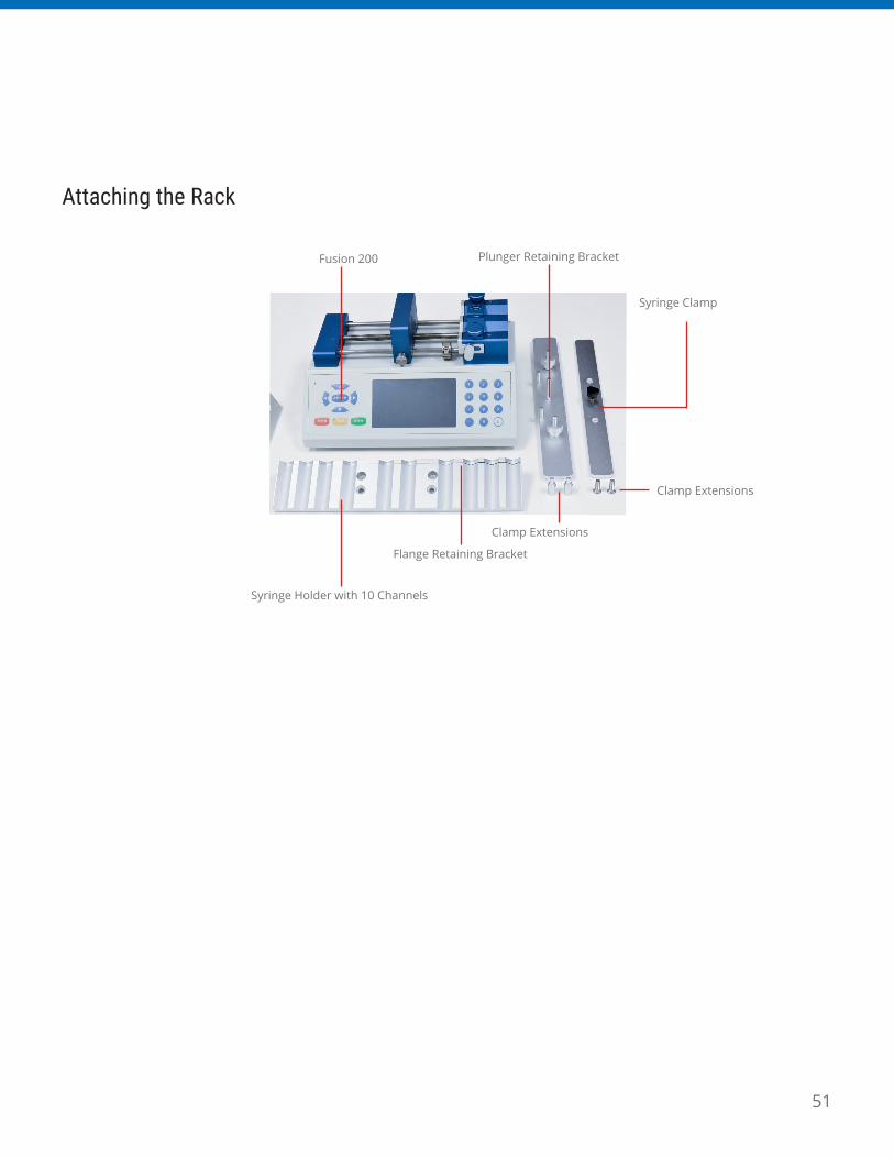
Attaching the Rack
Fusion 200
Syringe Holder with 10 Channels
Flange Retaining Bracket
Clamp Extensions
Clamp Extensions
Plunger Retaining Bracket
Syringe Clamp

52
Size Diameter
6.00mL 9.53mm
20.00mL 19.13mm
50.00mL 28.6mm
Size Diameter
0.50mL 4.64mm
1.00mL 4.64mm
2.00mL 8.93mm
2.50mL 8.66mm
3.00mL 8.93mm
5.00mL 11.73mm
10.00mL 14.68mm
20.00mL 19.60mm
30.00mL 22.70mm
50.00mL 28.03mm
60.00mL 28.60mm
Size Diameter
0.50μL 0.10mm
1.00μL 0.15mm
2.00μL 0.21mm
5.00μL 0.33mm
10.00μL 0.48mm
25.00μL 0.73mm
50.00μL 1.03mm
100.00μL 1.46mm
250.00μL 2.30mm
500.00μL 3.26mm
1.00mL 4.61mm
2.50mL 7.28mm
5.00mL 10.30mm
10.00mL 14.57mm
25.00mL 23.03mm
50.00mL 32.57mm
Size Diameter
1.00mL 4.64mm
3.00mL 4.64mm
5.00mL 12.07mm
10.00mL 14.50mm
20.00mL 19.13mm
30.00mL 21.69mm
60.00mL 26.72mm
Size Diameter
1.00mL 4.80mm
1.00mL 6.70mm
2.00mL 6.70mm
2.00mL 9.20mm
3.00mL 10.30mm
5.00mL 12.20mm
10.00mL 15.00mm
20.00mL 19.00mm
30.00mL 22.50mm
50.00mL 25.50mm
100.00mL 34.00mm
Chemyx Stainless Steel Hamilton Glass
Hoshi
BD Glass
BD Plastic
AppendicesAppendix A: Syringe Volume/Diameter Reference

53
Size Diameter
1.00mL 4.66mm
2.00mL 6.90mm
2.50mL 9.10mm
5.00mL 12.62mm
10.00mL 14.34mm
20.00mL 19.68mm
30.00mL 22.44mm
50.00mL 28.80mm
100.00mL 36.68mm
Size Diameter
0.25mL 3.45mm
0.50mL 3.45mm
1.00mL 4.50mm
2.00mL 8.92mm
3.00mL 8.99mm
5.00mL 11.70mm
10.00mL 14.70mm
20.00mL 19.58mm
30.00mL 22.70mm
50.00mL 29.00mm
Size Diameter
0.25mL 2.60mm
0.50mL 3.20mm
1.00mL 4.30mm
2.00mL 6.30mm
3.00mL 7.30mm
5.00mL 9.50mm
Size Diameter
2.00mL 9.12mm
5.00mL 12.34mm
10.00mL 14.55mm
20.00mL 19.86mm
30.00mL 23.20mm
50.00mL 27.60mm
Size Diameter
1.00mL 4.71mm
3.00mL 9.50mm
5.00mL 12.91mm
10.00mL 15.40mm
20.00mL 19.30mm
30.00mL 23.40mm
50.00mL 29.00mm
Size Diameter
1.00mL 4.70mm
2.50mL 9.70mm
5.00mL 12.48mm
10.00mL 15.89mm
20.00mL 20.00mm
30.00mL 22.50mm
50.00mL 28.90mm
JMC Air-Tite Plastic Norm-Ject Plastic
Popper & Sons Glass
Ranfac
Natsume
Nipro

54
Size Diameter
25.00μL 0.73mm
50.00μL 1.03mm
100.00μL 1.46mm
250.00μL 2.30mm
500.00μL 3.26mm
1.00mL 4.61mm
2.50mL 7.28mm
5.00mL 10.30mm
10.00mL 14.57mm
Size Diameter
1.00mL 4.70mm
2.00mL 6.40mm
3.00mL 9.30mm
6.00mL 13.10mm
12.00mL 15.40mm
25.00mL 21.00mm
30.00mL 23.00mm
50.00mL 29.00mm
Size Diameter
1.00mL 4.65mm
3.00mL 8.94mm
6.00mL 12.70mm
12.00mL 15.90mm
20.00mL 20.40mm
35.00mL 23.80mm
50.00mL 26.60mm
Size Diameter
1.00mL 4.73mm
3.00mL 9.00mm
5.00mL 13.04mm
10.00mL 15.79mm
20.00mL 20.18mm
30.00mL 23.36mm
60.00mL 29.45mm
Size Diameter
1.00mL 4.73mm
1.00mL 6.50mm
3.00mL 8.65mm
5.00mL 13.00mm
10.00mL 15.80mm
20.00mL 20.15mm
30.00mL 23.10mm
50.00mL 29.10mm
SGE Glass Terumo Japan
TopSherwood Plastic
Terumo

55
Size Diameter
10.00μL 0.46mm
25.00μL 0.73mm
50.00μL 1.03mm
100.00μL 1.46mm
250.00μL 2.30mm
500.00μL 3.26mm
1000.00μL 4.61mm
Size Diameter
1.00mL 4.65mm
3.00mL 8.94mm
6.00mL 12.70mm
12.00mL 15.90mm
20.00mL 20.40mm
35.00mL 23.80mm
60.00mL 26.60mm
Unimetrics
Kendall Monoject Plastic

56
Item Description Part Number
Fusion 100 Touch 07100
Fusion 200 Touch 07200
Fusion 400 Touch 07400
Item Description Part Number
Foot Switch (w/ USB-B connection cable) 50002
DB9 Serial Cable (Male-to-Female) 50007
USB Serial Cable (USB-B-to-USB-A) 50017
10-Channel Syringe Rack (Fusion 200 only) 50003
Item Description Part Number
Stainless-Steel Syringe (6 mL) SS6
Stainless-Steel Syringe (20 mL) SS20
Stainless-Steel Syringe (50 mL) SS50
O-Ring Replacement 10-pack (6 mL) CP6
O-Ring Replacement 10-pack (20 mL) CP20
O-Ring Replacement 10-pack (50 mL) CP50
Fusion Series Syringe Pumps
Options and Accessories
Stainless-Steel Syringes
Appendix B: Available Parts

57
Chemyx Inc.
10905CashRd.
Stafford,TX77477
Webpage:www.chemyx.com
ContactUs:www.chemyx.com/contact-us
Phone: +1 281-277-5499
Fax: +1 281-277-5499
OfficeHours:Monday–Friday,8:30am–5pm(CentralTime)
Formorearticlesandtutorialvideos,visit:www.chemyx.com/support
Follow Us
LinkedIn:www.linkedin.com/company/chemyx
Twitter:www.twitter.com/chemyxinc
Appendix C: Contact Information