Fusion of Infrared and Visible Images for Robust Person Detection
28
12 Fusion of Infrared and Visible Images for Robust Person Detection Thi Thi Zin, Hideya Takahashi, Takashi Toriu and Hiromitsu Hama Graduate School of Engineering, Osaka City University, Osaka 558-8585 Japan 1. Introduction In the current context of increased surveillance and security, more sophisticated and robust surveillance systems are needed. One idea relies on the use of pairs of video (visible spectrum) and thermal infrared (IR) cameras located around premises of interest. To automate the system, a robust person detection algorithm and the development of an efficient technique enabling the fusion of the information provided by the two sensors becomes necessary and these are described in this chapter. Recently, multi-sensor based image fusion system is a challenging task and fundamental to several modern day image processing applications, such as security systems, defence applications, and intelligent machines. Image fusion techniques have been actively investigated and have wide application in various fields. It is often a vital pre-processing procedure to many computer vision and image processing tasks which are dependent on the acquisition of imaging data via sensors, such as IR and visible. One such task is that of human detection. To detect humans with an artificial system is difficult for a number of reasons as shown in Figure 1 (Gavrila, 2001). The main challenge for a vision-based pedestrian detector is the high degree of variability with the human appearance due to articulated motion, body size, partial occlusion, inconsistent cloth texture, highly cluttered backgrounds and changing lighting conditions. Fig. 1. Typical dangerous situation – A child suddenly crossing the street Moreover, the applications, to protect pedestrians, define hard real-time requirements and rigid performance criteria. In night-time environment, only limited visual information can www.intechopen.com
Transcript of Fusion of Infrared and Visible Images for Robust Person Detection

12
Fusion of Infrared and Visible Images for Robust Person Detection
Thi Thi Zin, Hideya Takahashi, Takashi Toriu and Hiromitsu Hama Graduate School of Engineering, Osaka City University,
Osaka 558-8585
Japan
1. Introduction
In the current context of increased surveillance and security, more sophisticated and robust surveillance systems are needed. One idea relies on the use of pairs of video (visible spectrum) and thermal infrared (IR) cameras located around premises of interest. To automate the system, a robust person detection algorithm and the development of an efficient technique enabling the fusion of the information provided by the two sensors becomes necessary and these are described in this chapter. Recently, multi-sensor based image fusion system is a challenging task and fundamental to several modern day image processing applications, such as security systems, defence applications, and intelligent machines. Image fusion techniques have been actively investigated and have wide application in various fields. It is often a vital pre-processing procedure to many computer vision and image processing tasks which are dependent on the acquisition of imaging data via sensors, such as IR and visible. One such task is that of human detection. To detect humans with an artificial system is difficult for a number of reasons as shown in Figure 1 (Gavrila, 2001). The main challenge for a vision-based pedestrian detector is the high degree of variability with the human appearance due to articulated motion, body size, partial occlusion, inconsistent cloth texture, highly cluttered backgrounds and changing lighting conditions.
Fig. 1. Typical dangerous situation – A child suddenly crossing the street
Moreover, the applications, to protect pedestrians, define hard real-time requirements and
rigid performance criteria. In night-time environment, only limited visual information can
www.intechopen.com

Image Fusion
240
be captured by CCD cameras under poor lightning conditions, thus making it difficult to do
surveillance only by visual sensor. Meanwhile IR camera, that is IR sensor, captures thermal
image of object. Thermal image of pedestrian in night-time environment can be seen clearly
in IR video sequence used for this work. IR video provides rich information for higher
temperature objects, but poor information for lower temperature objects. Visual video, on
the other hand, provides the visual context to the objects. Thus, the fusion of the two videos
will provide good perceptibility to human vision under poor lightning condition. This will
help detect the moving objects (pedestrian) during night-time (Chen & Han, 2008).
Combining visible and thermal infrared images is advantageous since visible images are
much affected by lighting conditions while IR images provide enhanced contrast between
human bodies and their environment. However in outdoor conditions, it was noticed that IR
images are somewhat sensitive to wind and temperature changes. Nevertheless, these
limitations for both modalities are independent and usually do not occur simultaneously. In
the person detection and tracking literature, many approaches have been proposed to
combine the information from multiple sources, in order to provide more accurate and
robust detection and tracking. Probabilistic methods are commonly used to fuse information
sources (Malviya & Bhirud, 2009).
The term fusion in general means an approach to extract information acquired in several
domains. Image fusion is the process of combining relevant information from two or more
videos into a single image. The resulting image will be more informative than any of the
input image. The goal of image fusion is to integrate complementary multi-sensor, multi-
temporal and/or multi-view information into one new image containing information, the
quality of which cannot be achieved otherwise. An intelligent fusion of the information
provided by both sensors reduces detection errors, thereby increasing the performance of
tracking and the robustness of the surveillance system. A literature search reveals a few
interesting papers on the exploitation of near-infrared information to track humans
(Bertozzi et al., 2003). These papers generally deal only with the face of observed people and
a few are concerned with the whole body. However, when looking to the efforts in the
visible part of the spectrum for the same task, many papers are available such as (Masoud &
Papanikolopoulos, 2003). Surprisingly, the idea to couple visible and thermal infrared is not
yet seen as a popular research field for this application. One reason explaining this is
probably due to the still high cost of the thermal infrared cameras versus their visible
counter parts. Moreover outdoor scenarios are obviously more challenging to visible
imagery due to shadows, light reflections, levels of darkness and luminosity. However, on
the other hand, moving leaves and grass, cooling winds, moving shadows with clouds,
reflecting snow, etc., are challenging for IR imagery too. Thus, fusion of IR and visual image is a potential solution to improve person detection, tracking, recognition, and fusion performance (Wang et al., 2007). Tracking and recognition using the visual image is sensitive to variations in illumination conditions. On the other hand, tracking and recognition of targets based on IR images has become an area of growing interest. Thermal IR imagery is nearly invariant to changes in ambient illumination, and provides a capability for identification under all lighting conditions including total darkness. IR sensors are routinely used in remote sensing applications. Coupling an IR sensor with a visual sensor - for frame of reference or for additional spectral information - and properly processing the two information streams has the potential to provide valuable information in night and/or poor visibility conditions (Park et al., 2008).
www.intechopen.com

Fusion of Infrared and Visible Images for Robust Person Detection
241
In a review of video surveillance and sensor networks research (Cucchiara, 2005), it is said that the integration or fusion of video technology with sensors and other media streams will constitute the fundamental infrastructure for new generations of multimedia surveillance systems. Also reviewing surveillance research (Hu et al., 2004), it is worth to note on future developments in surveillance that surveillance using multiple different sensors seems to be a very interesting subject. Moreover, image fusion in multi-sensors has two advantages. First, multi-sensor image has inherent redundancy for each sensor because it can be fused each image from a various multi sensor. Second, multi-sensor differs from a single sensor because it is included information of each sensor and is separated information of object easily in real environments. The main problem is how to make use of their respective merits and fuse information from such kinds of sensors. The challenge remains whether using stationary or moving imagery system. This is due to a number of key factors like lighting changes (shadow vs. sunny day, indoor/night vs. outdoor), cluttered backgrounds (trees, vehicles, animals), artificial appearances (clothing, portable objects), non-rigid kinematics of pedestrians, camera and object motions, depth and scale changes (child vs. adult), and low video resolution and image quality. In this chapter, we shall propose a new approach to person detection that combines both thermal and visible information and subsequently models the motion in the scene using the multi-slit method and movement of Gravity Center (GC) patterns. Example images are shown in Figure 2 (Alex et al., 2007).
Fig. 2. Thermal image of the scene (left), visual image of the same scene (right)
To be specific, we shall briefly describe the problems, motivation, approach, challenges, and applications as follows.
1.1 Problems The detection of the moving persons has become more and more important over the past few years. Numerous applications in the area of security and surveillance are emerging. The objective of this chapter is to develop a new prototype system which combines an IR and visible sensor to enable the detection and surveillance of pedestrians over a period of time. More specifically, we will focus the problems in an environment where pedestrians are moving in a range of specified distances within an area affected by various lighting and atmospheric conditions.
1.2 Motivation The addition of an IR sensor will provide information which complements the images obtained in the visible range. Visible images offer a rich content where the detection of
www.intechopen.com

Image Fusion
242
people can however be limited by a change in lighting conditions. IR images generally allow a better contrast to be obtained between a person and the environment, but these images are not as robust to changes in temperature and wind conditions. An intelligent fusion of the information provided by both sensors could reduce false alarms and the advent of non detected pedestrians, thereby increasing the performance of a pedestrian detection and surveillance system.
1.3 Approach The detection of pedestrians is a process involving several interdependent steps. The quality
of the steps involving data acquisition, locating zones of movement, classification and
monitoring over time is crucial for a more robust detection. Data acquisition requires the
constitution of a database which combines sequences of visible and IR images obtained
under difference climatic and lighting conditions. The extraction of each region of interest
makes use of movement and is carried out independently for each sequence. A new
methodology for matching of the nominated regions of interest is developed using multi-
slits method and GC movement patterns .Finally, for the step involving the classification,
critical parameters indicating the presence of people are determined on the basis of
characteristics such as temperature, geometry and ratios compared to the rest of the
environment.
1.4 Challenges The detection and tracking of people in interior and exterior environments involves
numerous challenges. Systems treating the detection of people already exist in the
Computer Vision and Systems Laboratory and perform well for visible images (extraction of
regions of interest, geometric calibration). One of the challenges is to adapt these systems for
the treatment of IR images. Then, the respective limitations of the two sensors must be
clearly identified so as to extract the complementary information. The greatest challenge
involves the development of a method of intelligent fusion which will enable the robustness
of human detection to be improved while reducing false alarms and the advent of non
detected pedestrians. In this chapter, we will make some significant contributions to tackle
these challenges.
1.5 Applications The applications of a visible sensor for pedestrian detection and monitoring are already
numerous and can be applied to many public areas such as airports, train stations ,shopping
malls, parking lots, and etc.. With the addition of an IR sensor, these systems will become
more robust and will be able to function under varying lighting and climatic conditions,
both day and night, in summer as well as in winter.
2. Fusion of infrared and visible images
In many modern multi-sensor systems, fusion algorithms significantly reduce the amount of raw data that needs to be presented or processed without loss of information content as well as provide an effective way of information integration. Over the years there has been numerous image fusion algorithms developed to address the growing need for image fusion. The algorithms can be roughly divided into two groups; Multi-Scale-Decomposition
www.intechopen.com

Fusion of Infrared and Visible Images for Robust Person Detection
243
(MSD)-based fusion methods, and Non-Multi-Scale-Decomposition (NMSD)-based fusion methods (Blum, 2006). The basic idea of a MSD based fusion method is that a multi-scale transform is performed on the source images, and then a composite multi-scale representation of these images is constructed based on a predetermined selection rule. The fused image is obtained by taking the inverse of the original multi-scale transform. The most common MSD methods include pyramid transforms and Wavelet Transforms (WT). All NMSD are not based on multi-scale transforms. Most common NMSD fusion methods include, Principal Component Analysis (PCA), Weighted Average technique, Estimation Theory methods, and Artificial Neural Networks. Image fusion techniques can also be classified based on the level of processing where the fusion takes place (Hall, 2001). There are three main levels where image fusion may take place and they include:
• Pixel Level,
• Feature Level and
• Decision Level. Universal fusion system structure that illustrates them is shown in Figure 3.
Infrared camera
Visible camera
Pixel-level fusion
Feature-level fusion
Decision-level fusion
Decision makers
Scene observation
Feature extraction
Feature extraction
Feature extraction
Decision makers
Decision makers
Input image Input image
Feature set 1 Feature set 2
Fused feature set
Feature set 0
Fused pixel
Decision 1 Decision 2
Decision 0
Fused decision
Fig. 3. Universal fusion system architecture
Main difference between the levels is in the amount of processing that is performed on the image prior to fusion and hence the format in which this information is fused and the type of fusion techniques applied. The information is captured from an observation of the scene by the sensors, which present it to the system in form of two digital image signals (Input Images). These images can be combined directly (pixel-level fusion) into a fused image that represents the information present in the input images in a single signal. Alternatively, input images (and potentially the fused) can be processed (e.g. edge detection,
www.intechopen.com

Image Fusion
244
segmentation) to extract information about the basic features present in them. This information is of a more descriptive nature and can be combined from all cues into a single feature description set (fused feature set) by applying feature-level fusion techniques. This information then forms a basis for reaching decisions about (evaluating) the observed scene. Local decision makers produce probabilistic inferences about the scene from the feature sets provided by the lower level and these can be fused using decision level fusion techniques into a final evaluation (of the state) of the observed scene. This structure is important in the context of the concepts presented in this chapter since it illustrates well the one directional flow of information to obtain a more reliable and visually acceptable fused image.
2.1 Pixel level image fusion Image fusion at the pixel level means fusion at the lowest processing level referring to the merging of the physical parameters of the source images. Among the three fusion levels, pixel level fusion is the most mature and encompasses the majority of image fusion algorithms in the literature today. Figure 4 illustrates a schematic of pixel level fusion process.
Infrared image
Visible image
Pixel Fusion Validation Fused image
Infrared image
Visible image
Pixel Fusion Validation Fused image
Fig. 4. A schematic of pixel level fusion process
All input images are aligned first and then the algorithm is performed across the pixels of all the input images. Therefore, to perform pixel level fusion all input images need to be spatially registered exactly to all other input images, so that all pixel positions of all the input images correspond to the same location in the real world. There can be some generic requirements imposed on the fusion result from pixel level fusion:
• The fusion process should preserve all relevant information on the input imagery in the composite image (pattern conservation);
• The fusion scheme should not introduce any inconsistencies which would distract the human observer or following processing stages and
• The fusion scheme should be shift and rotational invariant, i.e. the fusion result should not depend on the location or orientation of an object in the input imagery.
The most common pixel level fusion algorithms are (i) a simple averaging technique, (ii) principle components analysis, (iii) pyramid fusion schemes and (iv)wavelet transforms (Discrete Wavelet Transform and Shift Invariant Discrete Wavelet Transform) etc.
2.2 Feature level image fusion Feature level methods are the next stage of processing where image fusion may take place. Fusion at the feature level requires extraction of objects (features) from the input images. These features are then combined with the similar features present in the other input images through a predetermined selection process to form the final fused image. Since, one of the essential goals of fusion is to preserve the image features, feature level methods have the
www.intechopen.com

Fusion of Infrared and Visible Images for Robust Person Detection
245
ability to yield subjectively better fused images than pixel based techniques (Samadzadegan, 2004). Common algorithms that fuse images at the feature level include edge detection methods and artificial neural networks. Figure 5 illustrates a schematic of feature level fusion process.
Feature extraction
Feature extraction
Infrared image
Visible image
Fusion based on joint features
Decision makers
Feature extraction
Feature extraction
Infrared image
Visible image
Fusion based on joint features
Decision makers
Fig. 5. A schematic of feature level fusion process
2.3 Decision level image fusion Decision level methods are at the highest level of processing where image fusion can take
place. Fusion at the Decision level takes Feature level fusion one step further by declaring
identities to the objects recognized, by the individual input images, and then assigning a
quality measure to the extracted features - See Figure 6. The obtained information is then
combined by applying decision rules to reinforce common interpretation and resolve
differences of the observed objects.
Feature extraction
Feature extraction
Infrared image
Visible image
Decision level fusion
Results
Object recognition
Object recognition
Feature extraction
Feature extraction
Infrared image
Visible image
Decision level fusion
Results
Object recognition
Object recognition
Fig. 6. A schematic of decision level fusion process
Due to fact that decision level fusion methods rely on the object recognition by all sensors in
order to produce a valid representation of the input images, if an object is not recognized by
all the sensors (via input images) then the output image will not utilize the full benefits of
image fusion (Gunatilaka & Baertlein, 2001). Decision level fusion also creates another
source of possible error when compared to the other fusion levels. If there is an error in
recognition of objects from one of the sensors this error will be transferred to the output
fused image. Some common algorithms used in decision level fusion include Fuzzy Logic,
Rule-based Fusion, and Bayesian Networks.
2.4 Fusion evaluation methods The ultimate aim of image fusion is to create a faithful and composite image that retains the important information from the source images while minimizing the noise caused by fusing the images. For the application, these images will be typically viewed and interpreted (perceived) by an operator. A number of evaluation approaches and metrics have been proposed to quantify and qualify image fusion performance: Fusion performance has been investigated using subjective and objective approaches.
www.intechopen.com

Image Fusion
246
2.4.1 Subjective evaluation approaches Two basic subjective evaluation approaches were noted in the literature, active or task
related (quantitative) and descriptive (qualitative). Quantitative approaches were utilized by
(Toet, 2001), (Dixon, 2006) where subjects assessed different fusion approaches on target
detection and recognition, as well as subject perception of situational awareness.
Quantitative fusion assessment has focused on the target detection, recognition and
situational awareness. Target detection and recognition assessment has been assessed in
naturalistic and in laboratory settings. By their nature, real time assessments are difficult to
duplicate, instead most fusion assessment experiments have focused on the capture of still
or live video of targets in operational settings. The fusion community has captured and
shared a number of multi-spectra reference images for algorithm development and
assessment. In addition to quantitative subjective tests, a large number of qualitative
evaluations have been undertaken to rate or rank the quality of fusion images evaluated
both target detection performance and fused image quality generated from four fusion
approaches. A variety of scales and methods have been used to evaluate the quality of
fusion images, typically a subject is asked to rank or rate the quality of the image on a linear
or ordinal scale. Three approaches are discussed in the literature (Petrovic, 2007), (Chen &
Varshney, 2005) simple ranking, Single Stimulus Continuous Quality Evaluation (SSCQE)
and Double Stimulus Continuous Quality Evaluation (DSCQE).
2.4.2 Objective evaluation approaches Objective measures utilize input images and the fusion image to develop a numerical score
of the success of the fusion process (Petrovic, 2007). And unlike subjective assessments
which have significant organizational and logistic requirements, objective measures can be
computed automatically. Objective metrics have also been developed to assess fusion
performance. Unlike traditional image quality metrics which use a “ground truth” image,
ideal fusion images are not available. Adjusting fusion filter bands, decomposition levels,
weighting parameters, window sizes, etc. will affect fusion performance.
A large number of objective measures have been proposed to evaluate fusion performance, these include Root Mean Square Error (RMSE), Image Quality (QW), Fusion Quality Measure (Q) to name a few. The objective measure can be classified into four categories:
• Methods based on statistical characteristics,
• Methods based on definition,
• Methods based on information theory and
• Methods based on important features. For image fusion, researchers have suggested a variety of objective measures to assess the success of the fusion. Ideally the researcher has developed a theory upon which to base the validity of their measure (theoretical constructs). Construct validity is the assessment of how well the researcher translated their theories into actual measures. The limited review of the literature did not identify theoretical constructs for many of the older statistical objective measures. Given the limitations of simple metrics, researchers have focused on developing metrics based on information theory and human perception (important features). Moreover, leading investigators in the image fusion community have indicated that they are now or soon will be, investigating task-specific fusion performance and the characterization of video fusion performance. The timing of the proposed fusion study in this chapter is thus occurring at an opportune time.
www.intechopen.com

Fusion of Infrared and Visible Images for Robust Person Detection
247
3. Potential applications of image fusion in surveillance
The objective of this section is to present a new robust pedestrian detection and tracking system which will exploit the information provided by a visible spectrum sensor and an IR sensor, while functioning within a complex environment. To-date, few detection and tracking systems have made use of IR information to track people (Xu & Fujimura, 2002). However, many researchers have addressed the same task using the visible part of the spectrum (Thi Thi Zin, 2009). The addition of an IR sensor will provide information which complements that obtained with visible images. The latter offer a rich content where the detection of pedestrians can however be limited by a change in lighting conditions. IR images generally enable a better contrast to be achieved between the pedestrian and his environment, but they are less robust to temperature and wind changes. Exploiting the complementary information obtained and improving the precision and robustness of tracking requires the development of an efficient technique allowing the fusion of this complementary information. Fusion of visible and IR information can be done at different levels in the image processing. Sensor fusion has become an increasingly important direction in computer vision and in particular human detection and tracking systems in recent years. In this section, we have considered a strategy where information from both channels is fused at the highest level. Obviously, the main part of the work concerns image processing. An important hypothesis is that cameras do not move during the recording of one given sequence. Figure 7 presents the overall image processing algorithm. After the image acquisition, moving regions are extracted with a newly developed background subtraction algorithm. Detection processing is performed at two levels: blob and object.
Acquisition
Infrared image Visible image
Acquisition
Background subtraction
Background subtraction
Blob detection Blob detection
Object detection Object detection
Fusion
Acquisition
Infrared image Visible image
Acquisition
Background subtraction
Background subtraction
Blob detection Blob detection
Object detection Object detection
Fusion
Fig. 7. Image processing flowchart
3.1 Two-level detection process The algorithms of the first segmentation often provide data where the people are detected in the form of several blobs surrounded by noise and lacking certain body parts. The detection algorithm presented here supports the incomplete and noisy data provided by the first segmentation. In order to do this, the processing is continued on two levels. While the first level of the algorithm consists in following the blobs in an image sequence (both visible and IR), the second level builds on the first and tracks a combination of one or more blobs, i.e. objects. The output results of this two level processing can illustratively described as shown in Figure 8.
www.intechopen.com

Image Fusion
248
Visible image V1 V2: V1 with smoke
I1: FIR image of V1I2: FIR image of V2
F1: Fused image of V1 and I2
Visible image V1 V2: V1 with smoke
I1: FIR image of V1I2: FIR image of V2
F1: Fused image of V1 and I2
Fig. 8. Image fusion for visibility improvement (Source of image: http://www.imagefusion.org)
3.2 Robust person detection in far infrared images Here, we propose two novel methods for robust person detection in Far Infrared (FIR)
images. The first one is a generalized method to be branded as a multi-slit method for
person detection with various standing postures at near and far distances. It is based on
body parts detection by using multi-slits to extract head region. Among many things, the
special feature of this multi-slit method using only a single camera is a key component and
provides monocular vision. This is a significant and advantageous step to move forward for
advances in person detection while other existing methods use more than one camera for
stereo vision. In our method, the combined approach of multi-slits with vanishing line is
also a new concept. The second one is a simplified method that is very useful at near
distances which is a sequential decision method using GC movement patterns. Moreover,
the simplified method makes a significant progress in differentiating person and non-person
in almost all environments. This is due to the use of GC movement patterns which has been
never seen in the existing literature. In both methods, we focus on a single frame person
detection algorithm using step-by-step approach. Figure 9 shows two proposed methods.
Input FIR
image
GC movement pattern method
Outputresult
Method2
Body parts detection method
Multi-slit method for head region extraction
Verifying nominated head regions
Method1
Input FIR
image
GC movement pattern method
Outputresult
Method2
Body parts detection method
Multi-slit method for head region extraction
Verifying nominated head regions
Method1
Fig. 9. Two novel methods for person detection
www.intechopen.com

Fusion of Infrared and Visible Images for Robust Person Detection
249
3.2.1 Multi-slit method using vanishing line This method consists of two major steps: (i) extracting head nominators by multi-slits and (ii) verifying nominated head regions. The multi-slit method utilizes y-position of vanishing line as the scale factor. The block diagram is shown in Figure 10(a).
3.2.2 Extracting head nominators by multi-slit method Each horizontal slit with height h(d) for a distance d is considered, for example, d = 5m, 6m, 7m, .… Our method can determine the position and height of each slit from the vanishing line in an input FIR image. This aspect is shown in Figure 10(b). For distance d, we use the following parameters which are the coordinates on an input FIR image.
InputFIR image
Extraction of head nominators
OutputVerification of nominated regions
Multi-slits using vanishing line
a)
y1(5)d = 5 m d = 10 m
x1(5)
vanishing point
h(5)/2
h(5)h(10)
(x∞
, y∞
)★
x2(5) x1(10) x2(10)
y2(5)
y2(10)
y1(10)
y0(5)
y0(10)h(5)/2
h(5)
h(10)
h(10)/2
h(10)/2y1(5)d = 5 m d = 10 m
x1(5)
vanishing point
h(5)/2
h(5)h(10)
(x∞
, y∞
)★
x2(5) x1(10) x2(10)
y2(5)
y2(10)
y1(10)
y0(5)
y0(10)h(5)/2
h(5)
h(10)
h(10)/2
h(10)/2
b)
t =174cm t'cm
y0(5) = y0'( 5), d=5m
y0(10) = y0'(10), d=10m
y∞
★
y∞
★
y1(10)y1'(5)
y1'(10)
y1(5)
(d′,t′) (d,t)
t =174cm t'cm
y0(5) = y0'( 5), d=5m
y0(10) = y0'(10), d=10m
y∞
★
y∞
★
y1(10)y1'(5)
y1'(10)
y1(5)
(d′,t′) (d,t)
(c)
Fig. 10. Multi-slit method: (a) block diagram, (b) multi-slits using vanishing line, (c) relation between yi(d) and yi′(d), i = 0,1
x1(d) and x2(d): x-positions of left and right side of head, respectively, y0(d): y-position of ground level, y1(d), and y2(d): y-positions of top and bottom of a head (a matched slit for a distance d),
y∝: y-position of vanishing line. For reference, we adopt a person 174cm tall standing at a distance of 5m. The parameters
x1(5), x2(5), y0(5), y1(5), y2(5), and y∞ are manually obtained:
x1(5)=331, x2(5)=362, y0(5)=341, y1(5)=102, y2(5)=140, and y∞ =195.
www.intechopen.com

Image Fusion
250
If the camera position and angle are not changed, then it is not necessary to update them. Under perspective projection, we can obtain the following equation for a distance d:
yi(d) = y∞ +5 (yi(5) - y∞)/d, i=0,1,2, (1)
when yi(d) ≠ y∞ , we get
(5)
5( )
i
i
y yd
y d y
∞∞
⎛ ⎞−= ⎜ ⎟−⎝ ⎠ . (2)
The above equation means that distance d can be computed after getting yi(d) by monocular
camera. In our experiments, y1(d) and y2(d) are used, and y0(d) is not used. If a head is
detected at a distance d using these reference parameters, we can consider a person t′ cm tall
standing at a distance d′ instead of a person 174cm tall standing at a distance d, for t′ and d′ which satisfy the following conditions.
0 0
0 0
(5) (5) ( ) ( ), 174, 1 ,2.
(5) (5) ( ) ( )i i
i i
y y y d y dtt i
t y y y d y d
′ ′ ′ ′′ − −= = = =− − (3)
Thus,
0 0 0 0(5) ( (5) (5)) (5) ( (5) (5)) (5),i i iy t t y y y t t y y y′ ′ ′ ′= − + = − + (4)
where 0 0( ) ( ), and ( ) and ( )i iy d y d y d y d′ ′= are y-positions of persons 174cm and t′cm tall at a
distance d, respectively. It is noted that the distance between the camera and a person with
height 174cm can be computed by Eq.(2), but some error is caused for a person with
different height t′cm. From Eq.(1), we obtain
( )( ) 5 (5) / .i iy d y y y d∞ ∞′ ′ ′ ′= + − (5)
Setting ( ) ( )i iy d y d′ ′ = in Eq.(1) and Eq.(5) and substituting Eq.(4), we obtain
0 0
(5) ( (5) )
(5) ( (5) ) ( (5) (5))i i
i i
y y t y yd d d
y y t y y t y y
∞ ∞∞ ∞
⎛ ⎞ ⎛ ⎞− −′ ′= =⎜ ⎟ ⎜ ⎟′ ′− − + −⎝ ⎠ ⎝ ⎠ (6)
This means that it is possible to find a person t′ cm tall standing at a distance d′ m using data
of a person 174cm tall standing at a distance dm as long as Eq.(6) is satisfied. If y0(d) or “y1(d)
and y2(d)” is obtained with satisfactory accuracy, then the distance d′ and the height t′ are
uniquely determined. But it is not straightforward calculation in practice because of using
low resolution images. For simplicity, here we suppose ( ) ( )1( ) ( )t t y d y y d y∞ ∞′ ′≈ − − .
We can extract head regions from vertical histogram (summation of pixel values) within
each slit. Then to find the Local Maximum (LM) of the vertical histogram, some operations
using morphological dilations with line shape Structuring Element (SE) are applied. Dilation
Dj using SEj are defined as:
,j jD SE V= ⊕ j = 1, 2, (7)
www.intechopen.com
Fusion of Infrared and Visible Images for Robust Person Detection
251
1 1 1 1 1
1 1 1
SE1
0 0 ⋅⋅⋅ 0 1 1 1
w
1 1 1 1 1 1SE2 w =x2(d)-x1(d)
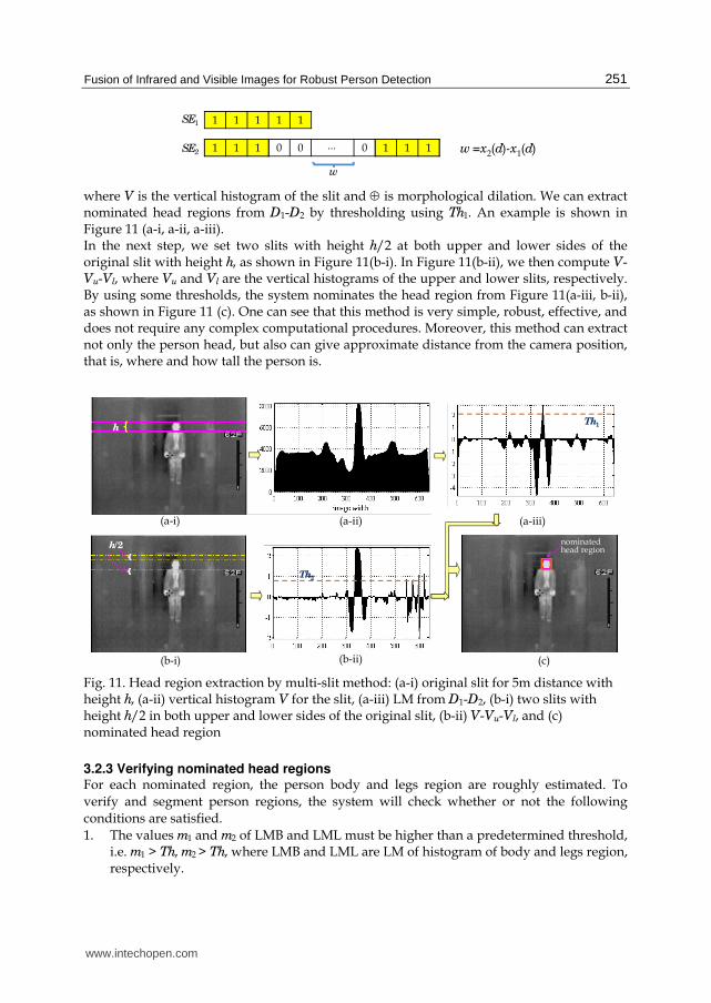
where V is the vertical histogram of the slit and ⊕ is morphological dilation. We can extract nominated head regions from D1-D2 by thresholding using Th1. An example is shown in Figure 11 (a-i, a-ii, a-iii). In the next step, we set two slits with height h/2 at both upper and lower sides of the original slit with height h, as shown in Figure 11(b-i). In Figure 11(b-ii), we then compute V-Vu-Vl, where Vu and Vl are the vertical histograms of the upper and lower slits, respectively. By using some thresholds, the system nominates the head region from Figure 11(a-iii, b-ii), as shown in Figure 11 (c). One can see that this method is very simple, robust, effective, and does not require any complex computational procedures. Moreover, this method can extract not only the person head, but also can give approximate distance from the camera position, that is, where and how tall the person is.
(c)
(a-i)
(b-i)
(a-ii) (a-iii)
(b-ii)
h
h/2nominated head region
Th1
Th2
Fig. 11. Head region extraction by multi-slit method: (a-i) original slit for 5m distance with height h, (a-ii) vertical histogram V for the slit, (a-iii) LM from D1-D2, (b-i) two slits with height h/2 in both upper and lower sides of the original slit, (b-ii) V-Vu-Vl, and (c) nominated head region
3.2.3 Verifying nominated head regions For each nominated region, the person body and legs region are roughly estimated. To
verify and segment person regions, the system will check whether or not the following
conditions are satisfied.
1. The values m1 and m2 of LMB and LML must be higher than a predetermined threshold, i.e. m1 > Th, m2 > Th, where LMB and LML are LM of histogram of body and legs region, respectively.
www.intechopen.com

Image Fusion
252
2. 1.2 3h b hw w w< < , where wb and wh are widths of body and head regions, respectively.
3. two x-positions of LMB and LML: one must be in the left side of the center of head region, another in the right side.
Although the conditions are defined as a whole, they are used as conditions for body
detection and legs detection separately. The roughly estimated rectangular regions are
determined as a person body and legs when all conditions for both body and legs are
satisfied. But, if all conditions for body or legs only are satisfied, then we will say that a
person is detected. These aspects are illustrated in Figure 12(a). In Figure 12(b), one example
of correct nominator is shown. The proposed algorithm is able to detect person regions for
various standing poses at near and far distances.
nominator
Sobel edge
His
tog
ram
0
His
tog
ram
0
body region legs region ☆ ☆
wb
wh
wl
…
☆
☆
His
tog
ram
0
His
tog
ram
0
body region legs region ☆ ☆
wb
wh
wl
…
☆
☆
a)
Sobel edge(body region)
Sobel edge(legs region)
his
tog
ram
(m
ean
)h
isto
gra
m (
mea
n)
pixels
pixels
wb
wl
nominated head region
b)
Fig. 12. Head Verification using histograms of body and legs regions: (a) Illustration of body and legs region, (b) example of correct nominator
www.intechopen.com

Fusion of Infrared and Visible Images for Robust Person Detection
253
3.3 Method using GC movement patterns In this section, we present a person detection method using GC movement patterns which
can segment by using appropriate threshold and differentiate human and other objects from
the inputs. This approach based on sequential decision process. The GCs of enlarging
connected regions have special movement patterns, if they are real head regions. By a
binarized image using an appropriate threshold ThI being changed in descending order, the
regions are obtained. So, the regions become larger and larger. These aspects are shown in
Figure 13. The GC movement patterns on each connected region for person are absolutely
different from the others (non-person). This fact is the key point of our approach. More
precisely, the GC of person moves slowly downward from the head regions and then goes
to the legs region rapidly after passing body region. Finally, the regions spread widely
including surrounding areas. In Figure 13(d), the red one is person region. Since this method
utilizes the GC movement patterns, it is able to recognize the gradual changes which occur
only in human body parts. Thus, this method can differentiate significantly human head
region and artificially made human-like head region as shown in Figure 14.
Generally, the temperature of person regions is higher than that of the environment and
their heat radiation is sufficiently high compared to the background. Therefore FIR imagery
is particularly suited to person localization. Obviously, other objects that actively radiate
heat, such as automobiles, trucks, busses, and motorcycles, heater, table lamp, have a similar
behavior. But, our simplified approach demonstrates to be able to differentiate person and
non-person from the GC movement patterns.
Peak: Th1
Main peak
Intensity
freq
uen
cy
X X
YY
a) b) d-i) d-ii)
Th1 Th1-α Th1-2α
Connected region 1
Connectedregion 2
c)
Fig. 13. GC movement pattern method: (a) input image, (b) smoothed histogram, (c) thresholding (thresholds are changing in descending order), (d-i) GC movement pattern (a person), and (d-ii) GC movement pattern (heater: non-person)
www.intechopen.com

Image Fusion
254
Human head
Artificial head
ThI ThI -10 ThI -20
ThI -10 ThI -20ThI
This is made of paper and heated for a while by toaster.
(1) (2) (3) (4) (5) (6)
(7) (8) (9) (10) (11) (12)
(1) (2) (3) (4) (5) (6)
(7) (8) (9) (10) (11) (12)
Human head
Artificial head
ThI ThI -10 ThI -20
ThI -10 ThI -20ThI
This is made of paper and heated for a while by toaster.
(1) (2) (3) (4) (5) (6)
(7) (8) (9) (10) (11) (12)
(1) (2) (3) (4) (5) (6)
(7) (8) (9) (10) (11) (12)
a)
(2),(3),(4)
Human head
(7),(8), (9),(10)
(11)
slowly
rapidly
(1)
(12)
rapidly in this case
unpredictable
Artificial head
(2),(3),(4), (5),(6),(7)
(1)
(9)
(10)
(8)
(2),(3),(4)
Human head
(7),(8), (9),(10)
(11)
slowly
rapidly
(1)
(12)
rapidly in this case
unpredictable
Artificial head
(2),(3),(4), (5),(6),(7)
(1)
(9)
(10)
(8)
b)
Fig. 14. Comparison of human head and artificial head: (a) enlarged regions due to changing threshold, (b) comparison of GC movement patterns
3.4 Image fusion algorithm for person detection The fusion or merging algorithm improves the precision of the size and position of the predicted or nominated area computed during the first level processing. It is driven by three goals. The first one consists in establishing a correspondence between the objects detected in the visible and the IR images. For each pair of objects, the identification of the best object detected (in visible or IR images) describes our second goal. The objects with the best detection are called master and the second one slave. The confidence is used as a criterion for better detection and is computed for all the objects of each frame in the sequence. In this manner the identification of the master and the slave will change rapidly for an object when fast light illumination or temperature variation is present. Our last goal consists in using the information of the master object to help in tracking the slave one. The merging process is done independently for each pair of objects. For example, if at time t, three objects can be detected in the visible and IR images, two objects can be master in the IR image, and one object can be a master in the visible image. The merging algorithm has to determine situations where the position and the size of the predicted area need to be modified. These situations only occur when a great difference between the primitive area of the master object
www.intechopen.com
Fusion of Infrared and Visible Images for Robust Person Detection
255
and the slave object is detected. In this case we enter in the “enslavement” mode where the master predicted area controls the slave predicted area. For example, if a pedestrian has a green T-shirt and walks in front of a green hedge, this person’s trunk will tend to disappear and the slave object will be put in the enslavement mode. The IR object will maintain a good detection and will help in tracking the pedestrian in the visible image because the body temperature is higher than the temperature of the green hedge. The fusion algorithm is very useful in cases where two objects disappear and will allow objects to stay present in the system and allow the position of the predictive area to be assessed using the mean speed of the predictive area in the last frame. For example, if a pedestrian passes behind a tree, the objects will disappear in both images. If the pedestrian maintains his speed and direction, the object will be recovered when it appears on the other side of the tree. But, if the pedestrian stopped behind the tree and returns to the same side, the algorithm will create a new object.
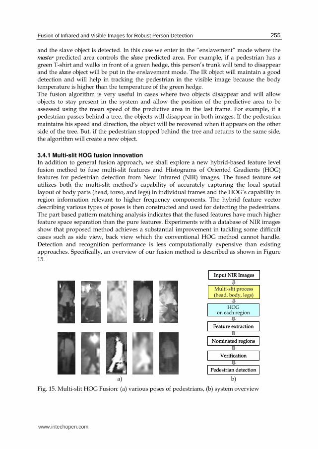
3.4.1 Multi-slit HOG fusion innovation In addition to general fusion approach, we shall explore a new hybrid-based feature level fusion method to fuse multi-slit features and Histograms of Oriented Gradients (HOG) features for pedestrian detection from Near Infrared (NIR) images. The fused feature set utilizes both the multi-slit method’s capability of accurately capturing the local spatial layout of body parts (head, torso, and legs) in individual frames and the HOG’s capability in region information relevant to higher frequency components. The hybrid feature vector describing various types of poses is then constructed and used for detecting the pedestrians. The part based pattern matching analysis indicates that the fused features have much higher feature space separation than the pure features. Experiments with a database of NIR images show that proposed method achieves a substantial improvement in tackling some difficult cases such as side view, back view which the conventional HOG method cannot handle. Detection and recognition performance is less computationally expensive than existing approaches. Specifically, an overview of our fusion method is described as shown in Figure 15.
Input NIR Images
Multi-slit process (head, body, legs)
HOG on each region
Feature extraction
Nominated regions
Verification
Pedestrian detection
Input NIR Images
Multi-slit process (head, body, legs)
HOG on each region
Feature extraction
Nominated regions
Verification
Pedestrian detection
a) b)
Fig. 15. Multi-slit HOG Fusion: (a) various poses of pedestrians, (b) system overview
www.intechopen.com

Image Fusion
256
The basic idea is that local object appearance and shape can often be characterized rather well by the distribution of local intensity gradients or edge directions, even without precise knowledge of the corresponding gradient or edge positions. In our system, these appearances will be described in a series of multi-slits for head, torso, and legs regions. The corresponding regions are extracted based on the properties of coplanar plane structures and distances. More precisely, vanishing line concepts are to be used for these purposes. We then divide the multi-slit into small spatial regions (cells), for each cell accumulating histogram of gradient directions or orientations over the pixels of the cell. The combined histogram entries form the representation. For better invariance to illumination, shadowing, etc., it is also useful to contrast-normalize the local responses before using them. This can be done by accumulating a measure of local histogram energy over somewhat larger spatial regions (blocks) and using the results to normalize all of the cells in the block. We will refer to the normalized descriptor blocks as Multi-slit HOG descriptors. The use of orientation histograms has been developed in many aspects, but it can only be reached maturity when combined with local spatial histograms and normalization in multi-slit approach to wide baseline image matching. So far our experiments show that even the best current approaches are likely to have false positive rates higher than our Multi-slit HOG approach for pedestrian detection. The procedure for the complete system starts detecting people in images by selecting a suitable sub-window from the top left corner of the image as an input for head, the second sub-window of different size for torso and the third for legs. These inputs are then independently classified by appropriate similarity measure as either a respective body parts or a non-body part and finally those are fused into a proper geometrical configuration in a full window as a person. All of these nominated regions are processed by the respective component features to find the strongest candidate components. The component detectors process the candidate regions by applying the modified HOG features and then these features become fusion data vector for respective classifications. In order to investigate the robustness and effectiveness of our proposed methods, experiments are carried out under various environments such as indoor, outdoor at daytime, outdoor at nighttime with distance variations. The results will be presented in the next section.
4. Experimental works and results
4.1 For FIR images The algorithms described in the previous sections was tested on several sequences under various environments such as indoor, outdoor at daytime, outdoor at nighttime with distance variations. Input images are taken originally by FIR camera 3600 AS by L3 Co. Ltd..
The horizontal view angle is 50° and the image resolution is 160×120. In this experimental setting, the selection of parameters is quite general even though we have used a particular type of camera. However, it is worthwhile to point out that using the particular type of camera can not be considered as a. limitation of our methods. Higher resolution cameras with more acute view angle will increase the precision and recall rate at further distances. Since the original image is captured through NTSC (National Television Standards
Committee), the digitized input image has the resolution 640×480. Some examples of head regions extracted by multi-slit method and our previous head shape-based method (Thi Thi Zin, 2007) for comparison are shown in Figure 16 and Figure 17, respectively.
www.intechopen.com

Fusion of Infrared and Visible Images for Robust Person Detection
257
at 6m distance
nominated head region
at 8m distancenominated head region
at 9m distancenominated head region
nominated head region
at 6m distance
nominated head region
at 8m distancenominated head region
at 9m distancenominated head region
nominated head region
Fig. 16. Head regions extracted by multi-slit method at (6m, 8m, 9m) distances
One of initial nominated head region
Top row of head
ML and MR LMVWidth of ML and MR
LMH
shoulder
)()()( ixixi LLL −+=∇ 1 )()()( ixixi RRR −+=∇ 1
Shortlist of nominated head regions
Larger than the mean value
Input FIR image
Morphological gradient
After noise removalInitial nominated head regions
(d)(a)
(b)
(c)
(e)
(f)(g)
Fig. 17. Head regions extracted by head shape-based method: (a) input FIR image, (b) thresholding, (c) MG using disk shape SE, (d) after noise removal, (e) initial nominated regions, (f) narrow down process on initial nominators, and (g) shortlist of nominated head regions
www.intechopen.com

Image Fusion
258
Concerning with head region extraction, it would be appropriate to present a brief outlines of our previous head shape-based method. The initial nominators of head regions are extracted using the intensity information in the process of thresholding and Morphological Gradient (MG). The pixels larger than the mean value of the whole image region are shown with white pixels in Figure 17(b). Generally, person heads close to ellipse shape, so we adopt MG using disk shape SE shown in Figure 17(c). In Figure 17(e), the initial nominated head regions are described with red rectangles. Among the extracted initial nominators of head regions, the next process will remove the incorrect nominators as many as possible. Figure 17(f) shows the narrow down process on Sobel edge of each nominator. To confirm the performance of the proposed method, the experiments are conducted in outdoor and indoor scenes including various postures at near and far distances. Some of images used in our experiment are shown in Figure 18.
FIR images at nighttime in outdoor scenes
FIR images at daytime in outdoor scenes
FIR images in indoor scenes
FIR images at nighttime in outdoor scenes
FIR images at daytime in outdoor scenes
FIR images in indoor scenes
Fig. 18. Example of images used in our experiments
To compare the performance of two methods, the precision rate (the ratio of number of correct detected regions to the total number of detected regions) and recall rate (the ratio of number of correct detected regions to the number of relevant correct regions) are shown in Figure 19. For method using GC movement patterns, a variety of experiments have been carried out to show wide range of applications. We conduct experiments on standing and sitting postures in indoor and outdoor together with experiments to differentiate real and artificial heads. According to our experiments, this method is highly stable under various conditions and postures at near distances. The results based on various environments are summarized in Figure 20. From Figure 19 and Figure 20, under almost all conditions, multi-slit method gives so high precision rates that the noise removal and verification processes are virtually unnecessary. The precision rate and recall rate for head shape-based method can be increased when the complete three processes (stage1 through stage3), initial nominator extraction, noise removal, and verification are applied. As a result, the multi-slit method is more effective for person detection than head shape-based method. In addition,
www.intechopen.com

Fusion of Infrared and Visible Images for Robust Person Detection
259
by multi-slit method, we can obtain the height of the detected person and the camera distance. The statement is also strengthened by calculations done from the geometrical point of view. Suppose that a person 174cm tall is standing at a distance 5m, the person with shorter height (say 165cm) standing at the same distance of 5m is detected at the distance of approximately 6m. This aspect is shown in Figure 21 with the relation between height and distance. Here, it would be appropriate to make a few remarks on the input of FIR camera resolution.
Nowadays, FIR cameras with image resolutions 320×240 and 640×480 are available at relatively low cost. Using such cameras with more acute view angle will increase the precision and recall rates at farther distances than 30m which we used in our experiment.
<5m 5m~10m 10m~15m >15m
distance
pre
cisi
on
/ r
eca
ll r
ate
precision rate (multi-slit method)
precision rate (head shape-based method: stage 3)
precision rate (head shape-based method: stage 2)
precision rate (head shape-based method: stage 1)
recall rate (multi-slit method)
recall rate (head shape-based method: stage 3)
Fig. 19. Precision and recall rates based on distances for multi-slit and head shape-based methods
multi-slit method head shape-based method: stage 3
head shape-based method: stage 2
head shape-based method: stage 1
GC movement patterns method
indoor outdoor at daytime
outdoor at nighttime
Pre
cisi
on
rat
e
Environments
Rec
all
rate
indoor outdoor at daytime
outdoor at nighttime
Environments
Fig. 20. Precision and recall rates based on environments for three methods
www.intechopen.com

Image Fusion
260
Person’s height (cm)
Dis
tan
ce (
m)
10m
5m
Reference: a person 174cm tall standing at distances 5m and 10m, respectively.
Person’s height (cm)
Dis
tan
ce (
m)
10m
5m
Reference: a person 174cm tall standing at distances 5m and 10m, respectively.
Fig. 21. The relation between person’s height (cm) and distance (m)
4.2 For fused images The fusion algorithms described in the previous sections was tested on several sequences. Various cases are illustrated in Figure 22 and Figure 23. It is obviously not possible to render the dynamics of these sequences in a paper and thus, some interesting situations were selected. In Figure 22, an indoor situation of multiple pedestrians standing in an office is presented. While the blob of one pedestrian is not well detected in visible image but it can be successfully detected in the IR image. In Figure 23 multiple outdoor pedestrians are shown where the blobs of some pedestrians at far distance are not well detected in visible images. It can be seen that those pedestrians are detected in the IR image. The fusion algorithm improved detection for the predicted area of this pedestrian.
4.2.1 Multi-slit HOG fusion experimental results We tested our detector on the well-established pedestrian database, containing 4 types of
training sets and 100 test images of pedestrians. It contains various views with a relatively
wide range of poses. Our detectors give essentially perfect results on this data set, so we
produced a new and significantly more challenging detector, Figure 24 shows some
samples. The people are usually standing, but appear in any orientation and against a wide
variety of background image including crowds. We have confirmed the effectiveness of our
proposed method under difficult illumination such as the influence of flare and also various
views of pedestrians including side view, back view, pedestrian carrying bag and so on.
(a) (b)
Fig. 22. Outdoor scene illustrating pedestrian extraction: (a, b) representation of the blob detected for both IR and visible images
www.intechopen.com

Fusion of Infrared and Visible Images for Robust Person Detection
261
(a) (b)
Fig. 23. Night scene showing pedestrian extraction: (a, b) representation of the blob detected for both IR and visible images
The people are usually standing, but appear in any orientation and against a wide variety of
background image including crowds. We have confirmed the effectiveness of our proposed
method under difficult illumination such as the influence of flare and also various views of
pedestrians including side view, back view, pedestrian carrying bag and so on. Moreover,
we can see that our fusion method (multi-slit & HOG) has better accuracy compared to
HOG of the conventional method. With a false positive rate of one digit percentages, our
method has 25% lower false negative rate than the HOG. This means that the appearance
and spatiotemporal features are suitable for people detection.
a) b)
c) d) e) f)
Fig. 24. Example of detected pedestrians: (a) the image is influenced by flare and pedestrian with bags from back view, (b) pedestrians are in the dark and from side view, (c) side view pedestrian, (d) back view pedestrian, (e) pedestrian in far distance, and (f) multiple pedestrians
www.intechopen.com

Image Fusion
262
5. Conclusion and image fusion research challenges
In this chapter, we presented person detection methods in FIR images and outlined image fusion approach for person detection. The implementation has been done to detect near and faraway persons. Among the proposed methods, the multi-slit method is easy to apply and does not require any complex computational techniques for head region detection. Moreover, we can state that multi-slit method is more robust than head shape-based method. On the other hand, the GC movement patterns method can detect the targeted regions with high accuracy especially at near distances. In addition, this approach has versatile application for various poses. Moreover, it can differentiate person and non-person. It is worthwhile to note that these methods would lead to further steps for person detection research by using FIR images. On the whole, through the proposed person detection methodology is by no means perfect for real world applications and it is still needed to further improve the detection performance. It has made much progress, considering the current research stages, and it presents encouraging results. Also, our approach collaborates with one another. Future work includes region-based image fusion for visibility improvement. The development of a visibility improvement is essential for poor vision at night, in bad weather, under smoke and so on. We also expect to consider for distance estimation of the person using FIR and visible images. Additional issues rise for future research widen application areas not only for night vision but also for finding people under smoke, flame, and for rescue at disaster site, and so on. Therefore, horizon of our proposed person detection algorithm can be widen and applied to the tasks of region-based fusion method using FIR and visible images. In this aspect, both thermal infrared and visible spectrum video have some fundamental, as well as technological differences. In certain scenarios, one modality might have particular advantages over the other. The challenge, therefore, is to develop techniques to automatically decide on which modality is best to use at any one time, or how best to combine them to play on their strengths and allow them to compensate for each other’s weaknesses. Presently, visible spectrum technology is far more developed than thermal infrared, which has only recently come to the consumer market, after years of military development. Therefore visible spectrum cameras have a superior resolution to thermal cameras. The standard visible spectrum camera has roughly six times more pixels than a thermal camera. The visible spectrum allows robust tracking of objects using their color and texture, when there is good lighting. However, there are many benefits to using thermal infrared. When an object has a temperature that is outside the background temperature distribution, it will have a very sharp edge around it in the thermal image. Thermal infrared video is also almost completely immune to lighting changes, as it depends primarily on emitted radiation. It can operate in total darkness when visible spectrum analysis would fail completely. The decimation/ saturation effect mentioned earlier can be very beneficial depending on the task at hand. If a segmentation mask is required, a simple thresholding of the thermal image can suffice. Future work will focus on further development of both low-level algorithms for modality fusion in a computer vision system and the use of these algorithms in an application. Low-level algorithms such as change-detection and segmentation have been extensively researched for single modality. The future challenge now is to understand how the current
www.intechopen.com

Fusion of Infrared and Visible Images for Robust Person Detection
263
state-of the- art can be used to benefit multimodal analysis, or whether new algorithms and fusion techniques are necessary to fully exploit the extra benefits of multiple modalities. Research into whether current methods of representational fusion can benefit analytical fusion is also of interest. Finally, the use of these low-level techniques in an application, such as people detection and tracking, will be the true test of their usefulness.
6. References
Anjali Malviya; Bhirud, S. G. (2009). Image Fusion of Digital Images, International Journal of
Recent Trends in Engineering, Vol. 2, No. 3, Nov. 2009, pp.146-148, ISSN 1797-9617 Bertozzi, M.; Broggi, A.; Grisleri, P.; Graf, T.; Meinecke, M. (2003). Pedestrian Detection in
Infrared Images, Proceedings of IEEE Intelligent Vehicles Symposium, pp. 662-667, ISBN, Columbus, USA, Jun. 2003
Blum, R. S.; Xue, Z.; Zhang, Z. (2006). An Overview of Image Fusion, Multi-Sensor Image
Fusion and Its Applications, In Blum, R. S., & Liu, Z (1 ed.), pp. 1-36, Boca Raton: Taylor & Francis
Chen, H.; Varshney, P. K. (2005). A perceptual quality metric for image fusion based on regional information, Proceedings of the SPIE: Multisensor, Multisource Information
Fusion: Architectures, Algorithms, and Applications, 2005, Vol. 5813, pp. 24-45 Chen, Y.; Han, C. (2008). Night-time Pedestrian Detection by Visual-Infrared Video Fusion,
Proceedings of 7th World congress on Intelligent Control and Automation, pp. 5079 - 5084, ISBN 978-1-4244-2113-8, Chongoing, China, Jun. 2008
Cucchiara, R. (2005). Multimedia surveillance systems, Proceedings of the 3rd ACM
International Workshop on Video Surveillance & Sensor Networks, New York, NY, USA, pp. 3-10, 2005
Dixon, T. D.; Canga, E. F.; Noyes, J. M.; Troscianko, T.; Bull, D. R. (2006). Methods for the assessment of fused images, ACM Transactions on Applied Perception, Vol. 3, No. 3, pp. 309-332
Gavrila, D. M. (2001). Sensor-based Pedestrian Protection, IEEE Intelligent Systems, Vol. 16, No. 6, pp. 77-81
Gunatilaka, A.; Baertlein, B. (2001). Feature-Level and Decision-Level Fusion of Noncoincidently Sampled Sensors for Land Mine Detection, IEEE Transactions on
Pattern Analysis and Machine Intelligence, Vol. 23, No. 6, pp. 577 – 589, ISSN 0162-8828
Hall, D.; Llinas J. (2001). Handbook of Multisensor Data Fusion, CRC Press, 2001 Hu, W.; Tan, T.; Wang, L.; Maybank, S. (2004). A survey on visual surveillance of object
motion and behaviors, IEEE Transactions on Systems, Man and Cybernetics, Vol. 34, No. 3, Aug. 2004, pp. 334- 350
Leykin Alex, Ran Yang, Hammoud Riad. (2007). Thermal-Visible Video Fusion for Moving Target Tracking and Pedestrian Classification, IEEE Conference on Computer Vision
and Pattern Recognition, pp. 1-8 Masoud, O.; Papanikolopoulos, N. (2003). A method for human action recognition, Image
and Vision Computing, Vol. 21, pp. 729-743, ISSN 0262-8856 Park, C.; Bae, K. H.; Choi, S.; Jung, J. H. (2008). Image fusion in infrared image and visual
image using normalized mutual information, Signal Processing, Sensor Fusion, and Target Recognition, Proceedings of SPIE, Vol. 6968, 69681Q, 2008
www.intechopen.com

Image Fusion
264
Petrovic, V. (2007). Subjective tests for image fusion evaluation and objective metric validation, Information Fusion, Vol. 8, No. 2, pp. 208-216, ISSN 1566-2535
Samadzadegan, F. (2004). Data Integration Related to Sensors, Data and Models, Proceedings
of International Society for Photogrammetry and Remote Sensing Thi Thi Zin, Pyke Tin, Hama, H. (2009). Bundling Multislit-HOG Features of Near Infrared
Images for Pedestrian Detection, Proceedings of 4th Intl. Conf. on Innovative
Computing, Information and Control (ICICIC2009), Kaohsiung, Taiwan, pp.302-305, 2009
Thi Thi Zin, Takahashi, H.; Hama, H. (2007), Robust Person Detection using Far Infrared Camera for Image Fusion, Proceedings of the 2nd Intl. Conf. on ICICIC 2007, Kumamoto, Japan, Sep. 2007.
Toet, A.; Ijspeert, J. K.; Kadar, I. (2001). Perceptual evaluation of different image fusion schemes, International Society for Optical Engineering Proceedings Series, 4380, pp. 427- 435
Wang, J.; Liang, J.; Hu, H.; Li, Y.; Feng, B. (2007). Performance evaluation of infrared and visible image fusion algorithms for face recognition, Proceedings of International
Conf. Intelligent Systems and Knowledge Engineering (ISKE2007), pp. 1-8, 2007 Xu, F.; Fujimura, K. (2002). Pedestrian Detection and Tracking with Night Vision, IEEE
Transactions on Intelligent Transportation Systems, Vol. 6, No. 1, Mar. 2005, pp. 67-71, ISSN 1524-9050
www.intechopen.com

Image FusionEdited by Osamu Ukimura
ISBN 978-953-307-679-9Hard cover, 428 pagesPublisher InTechPublished online 12, January, 2011Published in print edition January, 2011
InTech EuropeUniversity Campus STeP Ri Slavka Krautzeka 83/A 51000 Rijeka, Croatia Phone: +385 (51) 770 447 Fax: +385 (51) 686 166www.intechopen.com
InTech ChinaUnit 405, Office Block, Hotel Equatorial Shanghai No.65, Yan An Road (West), Shanghai, 200040, China
Phone: +86-21-62489820 Fax: +86-21-62489821
Image fusion technology has successfully contributed to various fields such as medical diagnosis andnavigation, surveillance systems, remote sensing, digital cameras, military applications, computer vision, etc.Image fusion aims to generate a fused single image which contains more precise reliable visualization of theobjects than any source image of them. This book presents various recent advances in research anddevelopment in the field of image fusion. It has been created through the diligence and creativity of some ofthe most accomplished experts in various fields.
How to referenceIn order to correctly reference this scholarly work, feel free to copy and paste the following:
Thi Thi Zin, Hideya Takahashi, Takashi Toriu and Hiromitsu Hama (2011). Fusion of Infrared and VisibleImages for Robust Person Detection, Image Fusion, Osamu Ukimura (Ed.), ISBN: 978-953-307-679-9, InTech,Available from: http://www.intechopen.com/books/image-fusion/fusion-of-infrared-and-visible-images-for-robust-person-detection

© 2011 The Author(s). Licensee IntechOpen. This chapter is distributedunder the terms of the Creative Commons Attribution-NonCommercial-ShareAlike-3.0 License, which permits use, distribution and reproduction fornon-commercial purposes, provided the original is properly cited andderivative works building on this content are distributed under the samelicense.