Fused Deposition of Ceramics (FDC) and Compositesedge.rit.edu/edge/P10551/public/SFF/SFF...
8
Fused Deposition of Ceramics (FDC) and Composites Seyi Onagoruwa, Susmita Bose and Amit Bandyopadhyay School of Mechanical and Materials Engineering Washington State University Pullman, WA 99164-2920 E-mail: [email protected] Abstract Fabrication of functional ceramics and composites has been attempted using fused deposition of ceramics process. In this work, first a polypropylene (PP) binder system has been developed for the FDM. The PP binder system was mixed with ceramic powders and then extruded in the form of filament for the FDC. Controlled porosity ceramic parts were directly fabricated using a FDM 1650 machine with mullite, fused silica and titania powder loaded green filaments. The parts were then binder removed and sintered. Some of the porous parts were then infiltrated in Al metal to form the metal-ceramic composites. This article discusses feedstock development, part fabrication and methods to improve the quality of parts during processing. Introduction Rapid prototyping (RP) or solid freeform fabrication (SFF) is a technique in manufacturing in which a solid physical model of a part is made directly from a three-dimensional computer-aided design (CAD) file. There are several RP techniques are available. Some of the most common RP techniques include stereolithography (SLA), selective laser sintering (SLS), fused deposition modeling (FDM), 3-D printing and sanders prototyping. Fused deposition modeling (FDM) is the RP technique used in this study. FDM, a solid-based RP technique, is commercialized by Stratasys Inc. (Eden Prairie, MN). FDM is an extrusion-based layered manufacturing process in which semi-solid thermoplastic polymers gets deposited on a platform through a nozzle fitted into a heated liquifier controlled in X and Y directions. The cold filament at the top of the liquefier acts as a piston, creating a positive pressure to extrude fine roads of molten material through the nozzle. The motion of the FDM head (X-Y direction) and platform (Z direction) is controlled by the computer, based on the CAD design of the prototype been built. After the head has completed the first layer, the platform indexes down set by the slice thickness and the second layer gets deposited on top of the first layer. This process continues until all layers are complete, leaving a solid model of the desired part. There are several variables that controls part quality in FDM. Among the materials related variables critical to FDM include surface chemistry, melt viscosity, stiffness, heat capacity and adhesiveness. Commercially available materials for FDM include wax, ABS and nylon. Fused deposition of ceramics (FDC) is a modified FDM process where ceramic powder loaded thermoplastic filaments are extruded through the FDM [1-4]. During fused deposition of ceramics, thermoplastic polymers melt carry the ceramic powders along with it. The green ceramic parts are similar to injection-molded parts having 40-45 volume % binder in it. The 224
Transcript of Fused Deposition of Ceramics (FDC) and Compositesedge.rit.edu/edge/P10551/public/SFF/SFF...
Fused Deposition of Ceramics (FDC) and Composites
Seyi Onagoruwa, Susmita Bose and Amit Bandyopadhyay School of Mechanical and Materials Engineering
Washington State University Pullman, WA 99164-2920
E-mail: [email protected]
Abstract
Fabrication of functional ceramics and composites has been attempted using fused deposition of ceramics process. In this work, first a polypropylene (PP) binder system has been developed for the FDM. The PP binder system was mixed with ceramic powders and then extruded in the form of filament for the FDC. Controlled porosity ceramic parts were directly fabricated using a FDM 1650 machine with mullite, fused silica and titania powder loaded green filaments. The parts were then binder removed and sintered. Some of the porous parts were then infiltrated in Al metal to form the metal-ceramic composites. This article discusses feedstock development, part fabrication and methods to improve the quality of parts during processing.
Introduction
Rapid prototyping (RP) or solid freeform fabrication (SFF) is a technique in manufacturing in which a solid physical model of a part is made directly from a three-dimensional computer-aided design (CAD) file. There are several RP techniques are available. Some of the most common RP techniques include stereolithography (SLA), selective laser sintering (SLS), fused deposition modeling (FDM), 3-D printing and sanders prototyping. Fused deposition modeling (FDM) is the RP technique used in this study. FDM, a solid-based RP technique, is commercialized by Stratasys Inc. (Eden Prairie, MN). FDM is an extrusion-based layered manufacturing process in which semi-solid thermoplastic polymers gets deposited on a platform through a nozzle fitted into a heated liquifier controlled in X and Y directions. The cold filament at the top of the liquefier acts as a piston, creating a positive pressure to extrude fine roads of molten material through the nozzle. The motion of the FDM head (X-Y direction) and platform (Z direction) is controlled by the computer, based on the CAD design of the prototype been built. After the head has completed the first layer, the platform indexes down set by the slice thickness and the second layer gets deposited on top of the first layer. This process continues until all layers are complete, leaving a solid model of the desired part. There are several variables that controls part quality in FDM. Among the materials related variables critical to FDM include surface chemistry, melt viscosity, stiffness, heat capacity and adhesiveness. Commercially available materials for FDM include wax, ABS and nylon. Fused deposition of ceramics (FDC) is a modified FDM process where ceramic powder loaded thermoplastic filaments are extruded through the FDM [1-4]. During fused deposition of ceramics, thermoplastic polymers melt carry the ceramic powders along with it. The green ceramic parts are similar to injection-molded parts having 40-45 volume % binder in it. The
224

parts are then subjected to a binder removal and sintering cycle for densification. The process development for FDC work requires optimization of thermoplastic binder composition, filament fabrication, FDC and binder burn out and sintering cycle development. Basic requirements for the development of the FDC feedstock filaments include low viscosity, high strength, high strain and high modulus. The high strength enables the filament to act as a piston during the FDC to prevent buckling. Low viscosity would prevent back flow of molten material. Binder system development is a major key to a successful FDC process. The binder system could be viewed as a parent that nurtures a child until the child is able to live on his/her own. Good properties of a binder system such as low viscosity, high strength, high strain, high modulus and easy binder burnout would enable the green filament to be easily fabricated in the FDC process into green structures and the green structures to survive the post processing. The properties of ceramic powders introduced into the thermoplastic binder system are very important too. The most important parameters one needs to consider when choosing ceramic powders are surface area, chemical composition, particle size and their distribution. Fine-grained, wide-size distribution ceramic powders lower the overall viscosity of the FDC mixture during compounding. When developing green filament, it is very desired to have the maximum solids loading of ceramics for reduced problems during post processing. Fabrication of the FDC feedstock such as mullite (3Al2O3, 2SiO2), fused silica (SiO2), titanium dioxide (TiO2), and alumina (Al2O3) involves three distinct processing steps. The first step involves the composition formulation of binder system and compounding of binder system and ceramic powder. The second step involves the extrusion of compounded mixtures into filament. The third step involves the FDC to fabricate high quality, structural parts. Binder removal and sintering are the post operations. Other post operations in the FDC process could include trimming or filing of seam lines in FDC parts while in the green state before binder removal and sintering. Good optimization of material and build parameters (e.g. head speed, flow rate, pre-flow, build temperatures) in the FDM software could prevent some of these post-processing operations.
Development of binder system for FDC
A binder system was developed from an in-house polypropylene-based FDM feedstock. The binder system was developed from commercially available thermoplastic materials. The prevalent components of the binder system are polypropylene base polymer, wax, tackifier, plasticizer and elastomer. Table 1 summarizes the role of each constituent material in the binder system and the FDC feedstock.
Binder constituent/s Characteristics Base polymer (polypropylene) Act as the backbone of the filament and gives
strength Tackifier Enables tackiness and provides flexibility Elastomer Provides elasticity and flexibility Plasticizer Provides plasticity to filament for spooling
Wax Reduces viscosity Table 1: FDC filament constituent/s and their characteristics
225

The base polymer gives strength to the entire filament. The role of the base binder is to act as the “backbone” or “strength giver” in the overall FDC feedstock formulation. The base polymer is the most difficult to choose, specifically because the other constituents are chosen to modify the properties of the base polymer. It should exhibit low viscosity, high strength, and good flexibility. The wax component in the FDC filament reduces the viscosity of the filament formulation. The tackifying component or tackifier provides tackiness and also increases the flexibility of the filament composition. The plasticizer provides plasticity and flexibility. It also provides some strength to the filament. The elastomer provides elasticity and flexibility. The elasticity in the filament helps to achieve a uniform feed rate during the FDC operation without any breakage of the filament. The elastomer also enables the filament to be spooled without any significant plastic deformation. Polypropylene, wax, tackifier, plasticizer, and elastomer are general names that represent different groups of materials that behave in a certain way or have almost same characteristics. These materials are produced by different manufacturers with different properties or characteristics. It’s the responsibility of the FDC feedstock developer to hand pick the best brand of polymer and additives that would produce a good binder system and eventual FDC feedstock. Mechanical testing was performed on several brands of materials from different groups and manufacturers. The vendor’s materials with the highest strength, highest strain, and lowest viscosity were selected as the FDC filament constituent for the composition formulation of the binder system. Experiment matrix as a technique of the DOE (Design of experiment) was used to organize and evaluate experimentation to obtain the best binder system composition. The matrix helps better understand what and how each constituent influences the base polymer and the binder system. The matrix was also used to understand how volume percent solids loading of ceramic powders influence the binder system and the corresponding FDC feedstock. The matrix contains results of mechanical testing (strength [MPa], strain [mm/mm], rheology torque [Nm]) of strategic compositions. Results of these various compositions and the outcome of sintered parts fabricated from the FDC feedstock were used to tailor a desirable binder system for the FDC. A binder system has been developed from the above methodology. The binder system has been used to load 55 volume % of mullite, fused silica, and titanium dioxide ceramic powders. The mullite feedstock in volume % comprises of 47.93% mullite powder + 6.85% alumina powder + 0.69% MgO + the developed binder system. The fused silica feedstock comprises of 53% fused silica + 3% MgO + the developed binder system. The titanium dioxide feedstock comprises of 51% titanium dioxide + 4% MgO + the developed binder system. The developed binder system is composed of 44% polypropylene + 13.9% elastomer + 18.7% plasticizer + 7.8% tackifier + 15.6% wax.
Filament fabrication for the FDC
Compounding of binder system and ceramic powders (mullite, fused silica, and titanium dioxide) was done with the aid of a Haake polylab system (Paramus, NJ). All FDC compositions were compounded at 180oC at roller speed of 120 rpm for 80 minutes in a 48.3 cm3-mixing bowl. The neat binder is first compounded for about 15 to 20 minutes before ceramic powders are added to the binder. Compounded mixtures are allowed to cool down to room temperature before they are
226
granulated into smaller size particles for extrusion. Ceramic powders especially fused silica tends to absorb moisture from the surroundings, which could reduce the strength of the FDC filament. Granulated compounded mixtures were subjected to moisture removal in a vacuum oven prior to filament extrusion. All the compounded mixtures were extruded at a screw speed of 7 rpm and 170oC (zone1) to 172oC (zone2) to 174oC (zone3) to 168oC (die zone) through a 1.78 mm diameter rod die. A horizontal conveyor belt was attached to the extruder for continuous fabrication of filament and subsequent spooling. The speed of the conveyor belt is very critical in obtaining a filament of 1.78 mm in diameter.
Fused deposition of ceramics
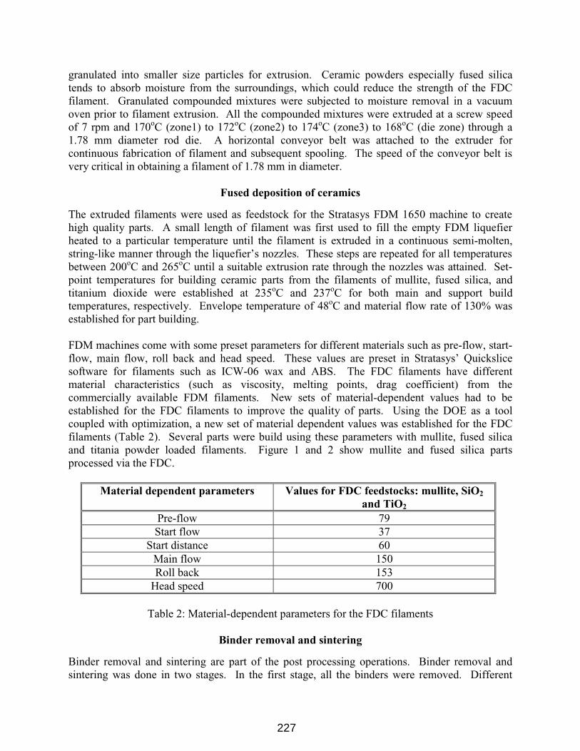
The extruded filaments were used as feedstock for the Stratasys FDM 1650 machine to create high quality parts. A small length of filament was first used to fill the empty FDM liquefier heated to a particular temperature until the filament is extruded in a continuous semi-molten, string-like manner through the liquefier’s nozzles. These steps are repeated for all temperatures between 200oC and 265oC until a suitable extrusion rate through the nozzles was attained. Set-point temperatures for building ceramic parts from the filaments of mullite, fused silica, and titanium dioxide were established at 235oC and 237oC for both main and support build temperatures, respectively. Envelope temperature of 48oC and material flow rate of 130% was established for part building. FDM machines come with some preset parameters for different materials such as pre-flow, start-flow, main flow, roll back and head speed. These values are preset in Stratasys’ Quickslice software for filaments such as ICW-06 wax and ABS. The FDC filaments have different material characteristics (such as viscosity, melting points, drag coefficient) from the commercially available FDM filaments. New sets of material-dependent values had to be established for the FDC filaments to improve the quality of parts. Using the DOE as a tool coupled with optimization, a new set of material dependent values was established for the FDC filaments (Table 2). Several parts were build using these parameters with mullite, fused silica and titania powder loaded filaments. Figure 1 and 2 show mullite and fused silica parts processed via the FDC.
Material dependent parameters Values for FDC feedstocks: mullite, SiO2
and TiO2 Pre-flow 79 Start flow 37
Start distance 60 Main flow 150 Roll back 153
Head speed 700
Table 2: Material-dependent parameters for the FDC filaments
Binder removal and sintering
Binder removal and sintering are part of the post processing operations. Binder removal and sintering was done in two stages. In the first stage, all the binders were removed. Different
227

heating rates were used in various temperature intervals to prevent surface and internal cracking of the samples. At low temperatures (< 200oC), liquid binder component(s) were removed via capillary action to the surrounding setter bed of alumina powder in which FDC parts were embedded. At a temperature over 200oC, evaporation and decomposition of the residual binders remove the remaining binders. The second stage is the sintering or densification stage. This was done at a temperature of 1650oC and hold time of 3 hours. These two stages of binder removal and sintering helped to fabricate high quality ceramic parts. Linear shrinkage after binder removal and sintering for the FDC part was established at 10-12% for mullite parts and 8-12% for fused silica parts. Figure 3 shows three sintered mullite parts.
FDC part quality
Visual inspection and the dimensional accuracy of FDC parts determined the part quality. The dimensional accuracy and tolerance of all the FDC parts were found to be very good in comparison to commercially available FDM feedstock for Stratasys’ FDM 1650 machine. Parts created were very close to the net shape and dimension of the CAD/STL files. All part dimensions were measured within +/- 1% of the original dimensions. Different types of defects in the FDC parts are classified into two main categories: (1) surface defects, (2) internal defects. Surface defects were minimal but visible to the naked eye. Two common surface defects are the staircase and chordal effect. Staircase defect is a common defect of most RP methods and is caused due to layered manufacturing. Reducing the thickness of each layer during operation can reduce this defect. Chordal effect originates in the STL format of the CAD. The STL is very similar to meshing in finite element analysis by approximating the surfaces of the CAD model with triangles. Highly curved surfaces must employ many triangles. The smaller the mesh sizes of curved surfaces, the better the quality of the fabricated model. Chordal effect was reduced by specifying binary mode and smallest chord length when exporting CAD files as STL files to the FDM machine. Similar part quality effects have also been discussed in Reference 5. Internal defects need to be addressed seriously if the part is going to be used as a functional component. Internal defects are product of hardware and software specifications and their limitations. The most common types of internal defects are sub-perimeter voids, inter-road voids and core voids. Sub-perimeter voids are created by incomplete filing of areas inside the fused deposition part. A void is created due to an insufficient material flow to fill the volume at the tangent path and actual perimeter path intersection. Specifying a negative offset (-0.003) to the perimeter in the Quickslice software rectified this defect. Inter-roads voids are created due to the inconsistent material flow of the FDC filaments. This defect is important because of the void it creates in the interior of the ceramic structure. Extruding the FDC filaments to near net size of 1.78 mm diameter, and increasing the flow rate of the FDC filaments to 130% reduced this defect. Core defects were attributed to parts with concentric circular features and created by improper road selection for the contour fill of an area. Specifying road widths that were ideal to both specified slice thickness and slice interval eliminated these defects. A detailed analysis related to different types of defects and tolerances are presented in Reference 6.
228
Metal-ceramic composites
Once the porous ceramic preforms (mullite and fused silica) are fabricated via the FDC process, some of the preforms were infiltrated with molten aluminum metal via pressure-less reactive metal infiltration to form interpenetrating metal-ceramic composite. In these composites, the metal as well as the ceramic phases are connected in all three directions to themselves. Some of the advantages of processing the metal-ceramic composites via the FDC route include: (1) microstructure and macro structures of the part can be designed simultaneously in CAD (2) volume fraction as well as phase distribution can be controlled by controlling the pore architecture. Figure 4a and b show the as-processed and polished microstructures of the mullite-Al composites. The uniformity in the metal phase distribution can be seen from these pictures. Both uniform as well as gradient composites can be fabricated by this method.
Conclusions
This study has demonstrated the process of developing a binder system for the FDC process. The developed binder system has been used in fabricating the FDC filaments for mullite, fused silica, and titanium dioxide. Green FDC parts were created from the filaments with features and appearance similar to those present in FDM processed wax and polymer parts. The green parts were successfully sintered to obtain fully dense ceramic parts with minimal or no defects. Porous ceramic parts of mullite, and fused silica have been infiltrated with aluminum metals to obtain metal-ceramic composites. Properties of these composite are currently being addressed as a function of their structural parameters.
References 1. T. F. McNulty, F. Mohammadi, A. Bandyopadhyay, D. J. Shanefield, S. C. Danforth and A.
Safari, “Development of Binder Formulation for Fused Deposition of Ceramics,” Rapid Prototyping Journal, 4 [4], pp 144-50 (1998).
2. A. Bandyopadhyay, R. K. Panda, T. F. McNulty, F. Mohammadi, S. C. Danforth and A. Safari, “Piezoelectric Ceramics and Composites via Rapid Prototyping Techniques,” Rapid Prototyping Journal, 4 [1], pp 37-49 (1998).
3. A. Bandyopadhyay, R. K. Panda, V. F. Janas, M. K. Agarwala, S. C. Danforth and A. Safari, “Processing of Piezocomposites by Fused Deposition Technique,” Journal of the American Ceramic Society, 80, 1366-72 (1997).
4. M. K. Agarwala, A. Bandyopadhyay, R. V. Weeren, N. A. Langrana, A. Safari, S. C. Danforth, “Fused deposition of ceramic (FDC) for Structural Silicon Nitride Components,” Proceedings. Solid Freeform Fabrication Symposium, Austin, TX, 1996.
5. R. van Weeren, M. Agarwala, V. R. Jamalabad, A. Bandyopadhyay, R. Vaidyanathan, N. Langrana, A. Safari, P. Whalen, S. C. Danforth, C. Ballard, “Quality of parts processed by fused deposition,” Proceedings. Solid Freeform Fabrication Symposium, Austin, TX, 1996.
6. S. Onagoruwa, MS Thesis, Mechanical and Materials Engineering, Washington State University, August 2001.
229

(a) (b)
Figure 1: (a) and (b) Mullite parts fabricated via FDC.
Figure 2: Green, brown and sintered fused silica parts via FDC. Three metal infiltrated parts can
also be seen in the back of the picture.
Figure 3: Sintered mullite parts processed via FDC
230

(a)
(b)
Figure 4: (a) As-processed mullite-Al composites. (b) Microstructures of mullite-Al composites.
231