Fundamentals of Generator Protection of Generator Protection.pdfHow is the Generator Relay Set...
124
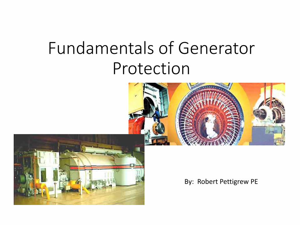
Fundamentals of Generator Protection By: Robert Pettigrew PE
Transcript of Fundamentals of Generator Protection of Generator Protection.pdfHow is the Generator Relay Set...
Fundamentals of Generator Protection
By: Robert Pettigrew PE
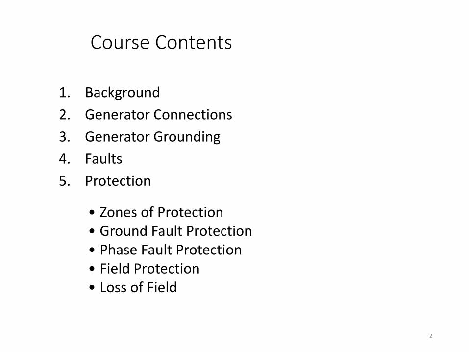
Course Contents
1. Background
2. Generator Connections
3. Generator Grounding
4. Faults
5. Protection
2
• Zones of Protection • Ground Fault Protection • Phase Fault Protection • Field Protection • Loss of Field
Course Contents
• Unbalanced Current Protection
• Overload Protection
• Reverse Power
• Overexcitation
• Overvoltage
• Abnormal Frequency
• Out of Step
• System Backup
3
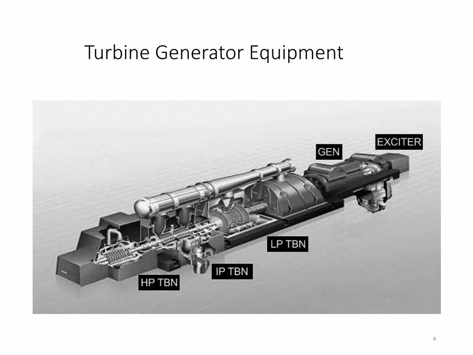
Turbine Generator Equipment
4
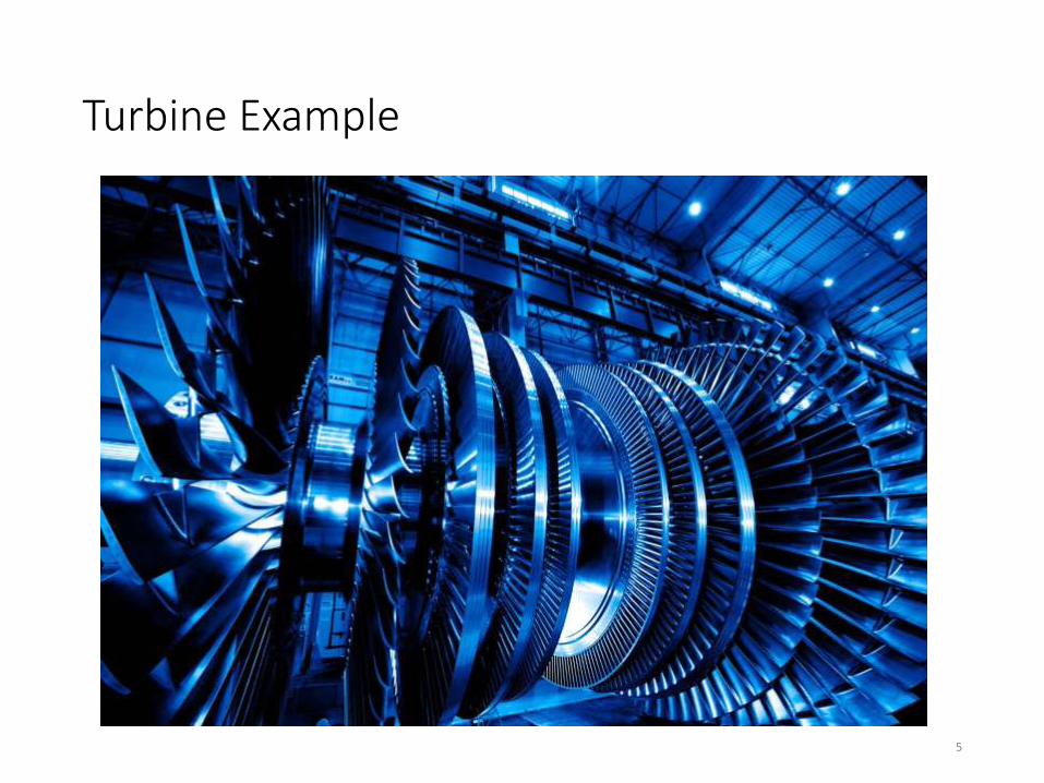
Turbine Example
5

6
Large Stator

7
8
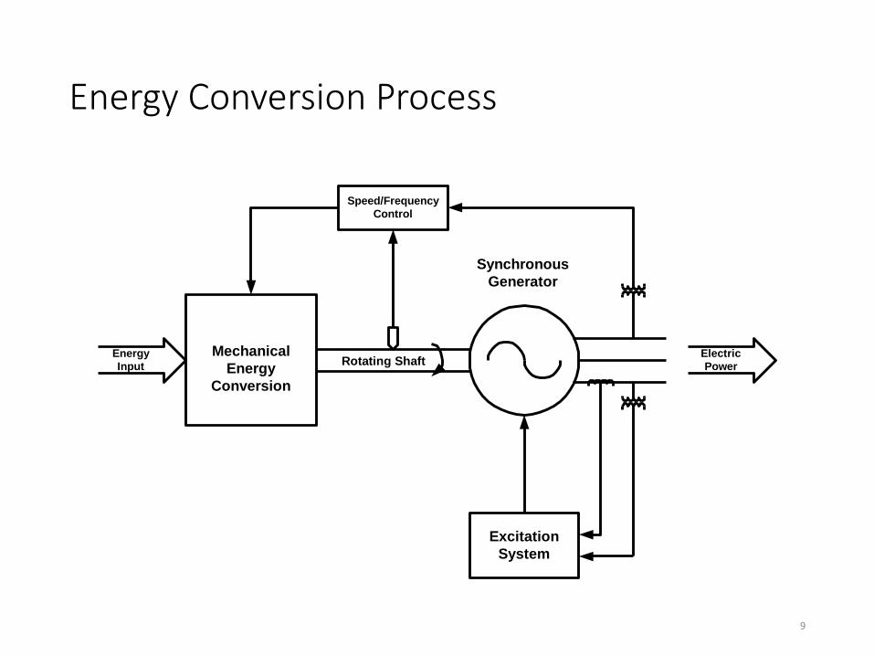
Energy Conversion Process
Mechanical
Energy
Conversion
Speed/Frequency
Control
Excitation
System
Energy
Input
Electric
Power
Synchronous
Generator
Rotating Shaft
9
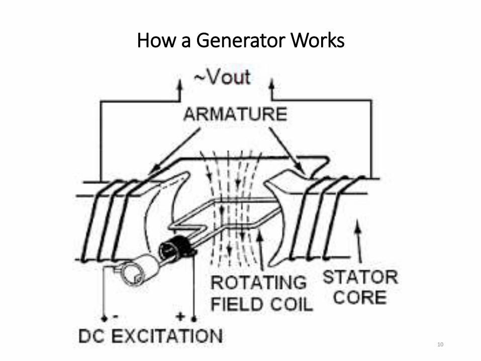
How a Generator Works
10

Generator Equation
• Operation principle of a Generator is based on Electromagnetic Induction, which is defined by Faraday’s Law, which states:
11
For additional details go to: https://opentextbc.ca/physicstestbook2/chapter/electric-generators/
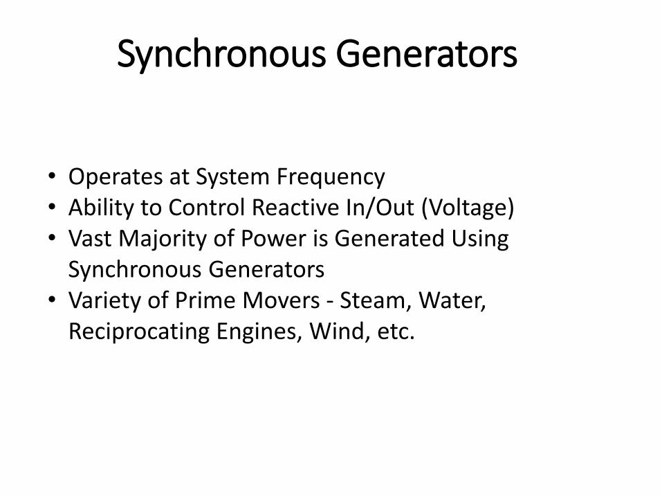
Synchronous Generators
• Operates at System Frequency • Ability to Control Reactive In/Out (Voltage) • Vast Majority of Power is Generated Using
Synchronous Generators • Variety of Prime Movers - Steam, Water,
Reciprocating Engines, Wind, etc.

13
Exciters & Voltage Regulators
14
•Exciter - An auxiliary generator used to provide field current for a larger generator or alternator
•Voltage Regulator – Controls operation of exciter to provide proper control of field current

Self Excited
15 Cummins T-030 Application manual
Note: Occasionally Phase CT’s used to provide exciter power during short circuits (Series Boost)
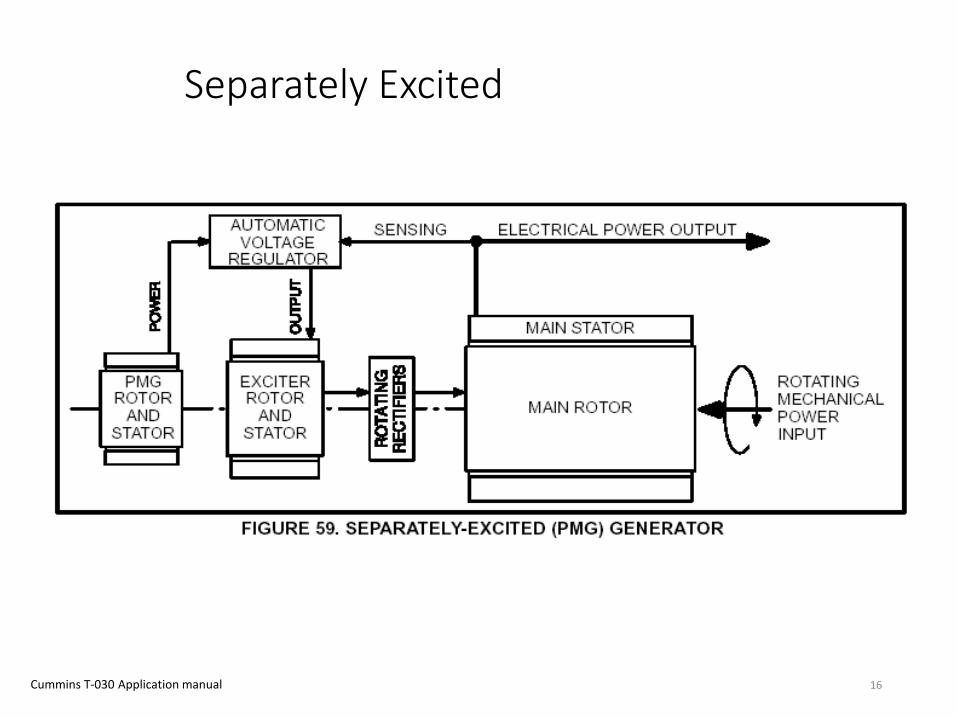
Separately Excited
16 Cummins T-030 Application manual

Generator Protection
17
Power-system protection is a branch of electrical power engineering that deals with the protection of electrical power systems from faults through the disconnection of faulted parts from the rest of the electrical network.

Device Function Numbers (ANSI C37.2)
Device Function
21 Phase Distance
51V Voltage Controlled/Restrained Overcurrent
24 Volts per Hertz
32 Reverse Power
40 Loss of Field
46 Negative Sequence Overcurrent
50/51 Instantaneous/Time Delayed Overcurrent
50/51GN Instantaneous/Time Delayed Overcurrent in Gen Neutral
51TN Time Overcurrent Relay in GSU Neutral
59 Overvoltage
59GN Ground Overvoltage
60 Voltage Balance
63 Fault Pressure
64F Rotor Ground Fault
78 Loss of Synchronism
81 Frequency (Over or Under)
87 Phase Differential
87G Generator Ground Differential
87T Transformer Differential
87O Overall Differential
18 https://en.wikipedia.org/wiki/ANSI_device_numbers
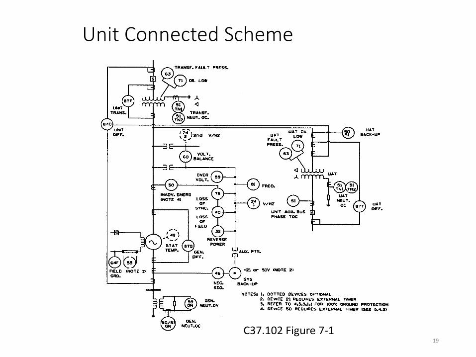
Unit Connected Scheme
19
C37.102 Figure 7-1

Settings Team • Customer engineer
• Project Manager
• Settings engineer
• Checking engineer
• Installation technician
• Commissioning engineer
20
• This group is a team that has to work together to provide a successful outcome.
• Communication between the team members is vital for a successful outcome.
• The Project Manager provides a communications channel to the customer.
• False operation of the relay system will be very costly to the generator owner. This can result in lost future business and economic damages.
How is the Generator Relay Set
• Customer may have Standards that determine how the unit is protected. If not utility standard practices are followed.
• Project manager and customer set the schedule and budget.
• Relay setting engineers develop the settings and produce a settings report and settings files that are to be loaded into the digital relays.
• Checking engineers will review and separately calculate the settings to verify the settings engineers work.
• All discrepancies are reported back to the settings engineer.
• A final set of settings and final settings report is then produced
• Checking engineers will verify the discrepancies have been properly addressed.
• The Poject Manager then sends the final report and final settings files to the customer.
• Customer/contractor technicians will install the relay into the relay panels. Any discrepancies will be noted to the design and settings engineers
21

How is the Generator Relay Set
• Customer may then have comments and request changes
• Settings engineer will address the customer comments and the checking engineer will verify the changes
• Commissioning engineers will then be given the settings files and settings report and load the settings into the digital relays.
• Commissioning engineers will then run simulations of the system faults to verify the settings provide proper operation of the relay.
• Any discrepancies go back to the settings engine er who will determine if the commissioning comments are valid and if valid will make the appropriate changes.
• Checking engineer will validate the changes in the settings and inform the settings engineers if OK or not.
• When this is completed and the relay is ready to be put in service the final settings and final settings report is sent to the customer for their files.
22
False Trip – An unnecessary or incorrect trip
•Can cost the owner millions of dollars in lost revenue and penalties
•Could cause a system blackout that may take hours or days to re-establish the grid voltage.
•Can be detrimental to the setting engineers career
23
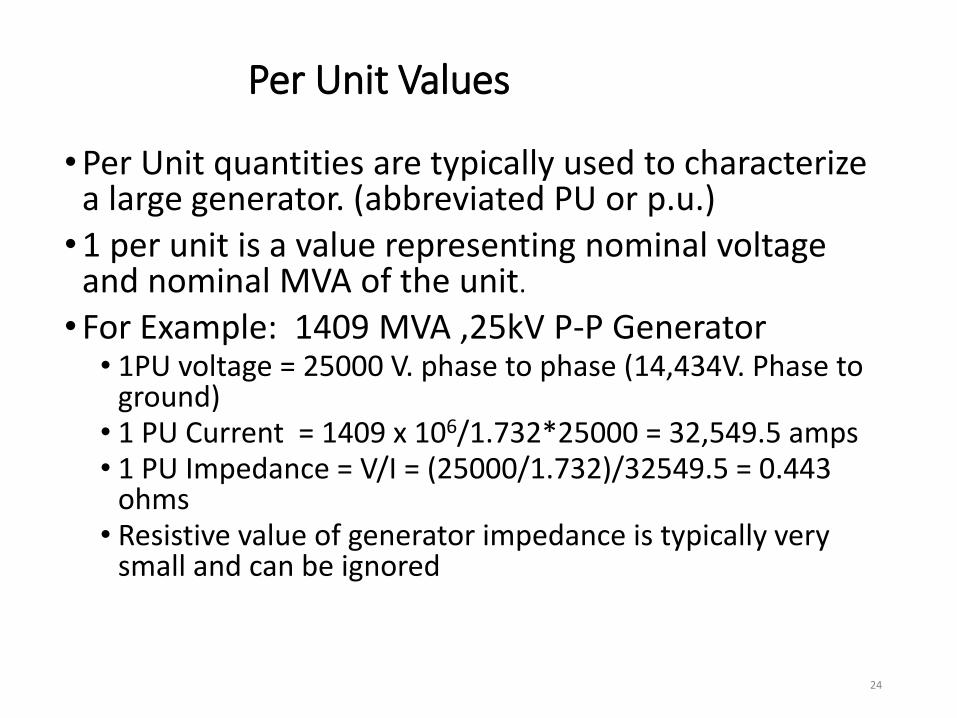
Per Unit Values
•Per Unit quantities are typically used to characterize a large generator. (abbreviated PU or p.u.) •1 per unit is a value representing nominal voltage
and nominal MVA of the unit.
•For Example: 1409 MVA ,25kV P-P Generator • 1PU voltage = 25000 V. phase to phase (14,434V. Phase to
ground) • 1 PU Current = 1409 x 106/1.732*25000 = 32,549.5 amps • 1 PU Impedance = V/I = (25000/1.732)/32549.5 = 0.443
ohms • Resistive value of generator impedance is typically very
small and can be ignored
24
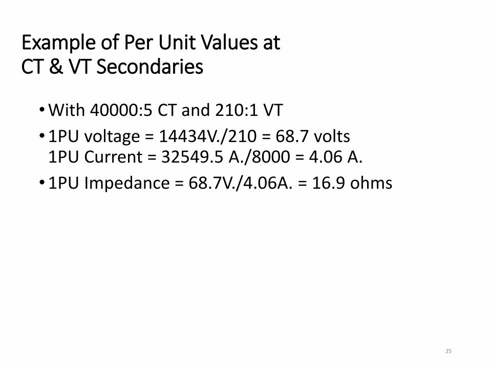
Example of Per Unit Values at CT & VT Secondaries
•With 40000:5 CT and 210:1 VT
•1PU voltage = 14434V./210 = 68.7 volts 1PU Current = 32549.5 A./8000 = 4.06 A.
•1PU Impedance = 68.7V./4.06A. = 16.9 ohms
25

Sequence Networks – Symmetrical Components
• In 1918 Charles Fortescue presented a paper which demonstrated that any set of N unbalanced phasors (that is, any such polyphase signal) could be expressed as the sum of N symmetrical sets of balanced phasors, for values of N that are prime. Only a single frequency component is represented by the phasors.
• In 1943 Edith Clarke published a textbook giving a method of use of symmetrical components for three-phase systems that greatly simplified calculations over the original Fortescue paper. In a three-phase system, one set of phasors has the same phase sequence as the system under study (positive sequence; say ABC), the second set has the reverse phase sequence (negative sequence; ACB), and in the third set the phasors A, B and C are in phase with each other (zero sequence, the common-mode signal). Essentially, this method converts three unbalanced phases into three independent sources, which makes asymmetric fault analysis more tractable.
• The sequence impedance network is defined as a balanced equivalent network for the balanced power system under an imagined working condition so that only single sequence component of voltage and current is present in the system. The symmetrical components are useful for computing the unsymmetrical fault at different points of a power system network.
• Computer programs today still use these concepts to do fault calculations
26
https://en.wikipedia.org/wiki/Symmetrical_components
Generator Protection
• Most Comprehensive Protection of any Power System Component
• Internal Faults
• External Faults
• Abnormal System Conditions
• Prime Mover Disturbances
27

Generator/System Connection
•Unit Connected
•Directly Connected
•Multiple Units Bus Connected
•Unconnected (Isolated Load)
28
Unit Connected
•Used for large units
•Delta – Wye step up transformer used to provide zero sequence isolation between the generator and the system
•Plant auxiliary loads fed from generator output
•Requires independent auxiliary source for startup and shutdown
29
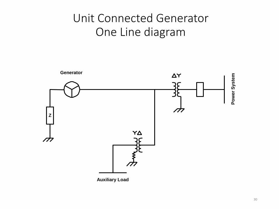
Unit Connected Generator One Line diagram
Z
Generator
Auxiliary Load
Po
we
r S
ys
tem
30
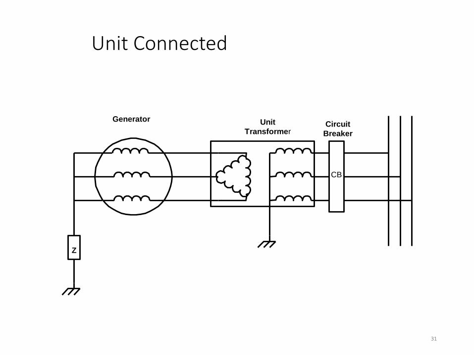
Unit Connected
CB
Generator Unit
TransformerCircuit
Breaker
Z
31

32
High Impedance Grounding
CB
Generator Unit
TransformerCirciit
Breaker
Grounding
Transformer R

High Impedance Grounding
• Limit Ground Fault Current to 5 – 10 amps.
•Distribution Transformer & Secondary Resistor typically used to create high value resistance.
•Phase Differential Relays will not see fault
•Difficult to detect ground faults near the neutral
•Faults at terminals create full neutral voltage shift
•Transient Overvoltage limits maximum value of impedance that can be used
33

34
CB
Generator Unit
TransformerCirciit
Breaker
Grounding
Transformer R
High Impedance Grounding
R' = Vlg/If R = R'/N2
If

1Φ Ground Fault Current Without Ground Impedance
35
Ia1 = Ia2 = Ia0
IN = 3•Ia0 = IF
Van
X1 + X2 + X0 + 3ZN
Ia0 =
Ia0 = 1.0
0.14 + 0.14 + 0.08 + 0
= 2.8 p.u.
IN = 3* Ia0 = 8.4 p.u.
I a0 3Z N
X 2
I a1
I a2
X 1
X 0
I a0
V an +
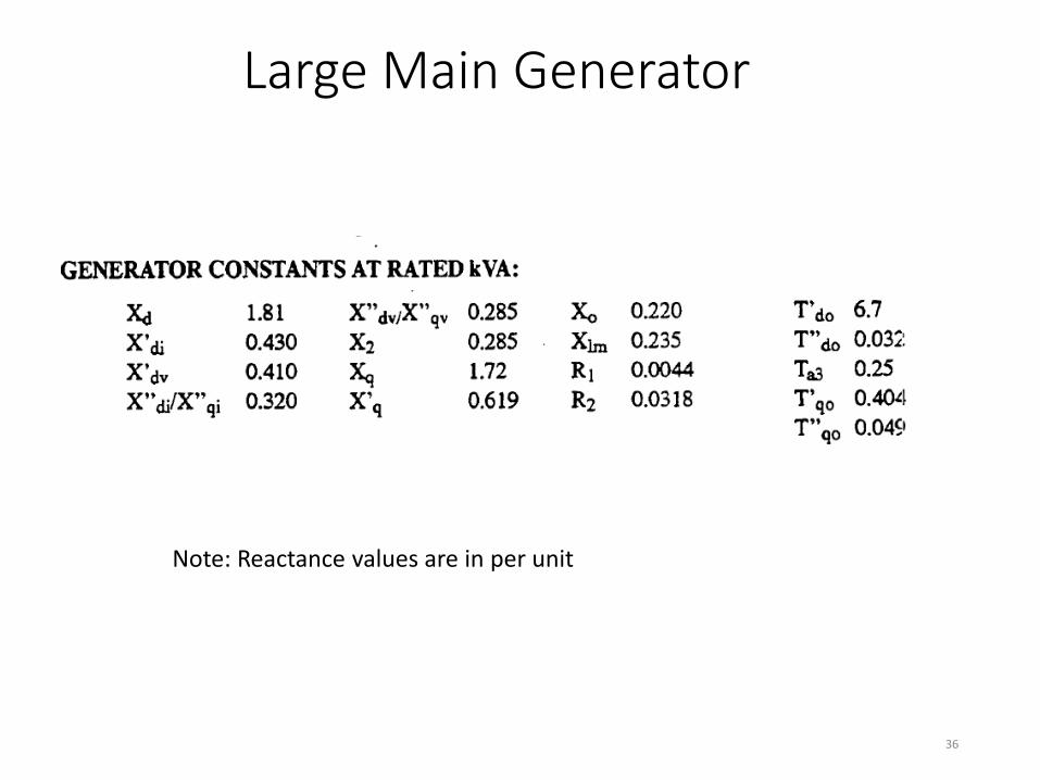
Large Main Generator
36
Note: Reactance values are in per unit
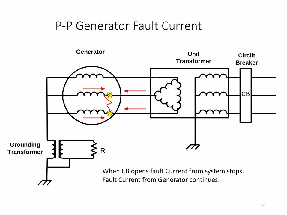
P-P Generator Fault Current
CB
Generator Unit
TransformerCirciit
Breaker
Grounding
Transformer R
37
When CB opens fault Current from system stops. Fault Current from Generator continues.

How to Protect?

Object of Protection System
• Detect fault conditions (sensitivity)
• Perform correctly when needed (reliability)
• Ignore faults outside the primary or backup zones of protection (selectivity)
• Operate rapidly, minimize damage (speed)
• Tolerable system cost vs. unit importance
• Minimum equipment used (simplicity)
39

Setting Example – Ground Fault
• Line to ground voltage = 14434 V (25kV P-P)
•Grounding Transformer Ratio = 14400/240 = 60
•Maximum Voltage = 14434/60 = 240.6 V
•Setting of 5.6 volts should give protection for 98% of stator winding.
•Exact coverage depends on residual 60Hz in neutral with unit on line (5 to 10 V. typical setting)
•Time delay used for coordination with VT fuses and system faults
40
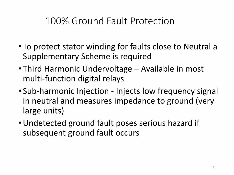
100% Ground Fault Protection
•To protect stator winding for faults close to Neutral a Supplementary Scheme is required
•Third Harmonic Undervoltage – Available in most multi-function digital relays
•Sub-harmonic Injection - Injects low frequency signal in neutral and measures impedance to ground (very large units)
•Undetected ground fault poses serious hazard if subsequent ground fault occurs
41

Third Harmonic Undervoltage
•Third Harmonic in three phases add as Zero Sequence current in Neutral •A fault near the neutral will shunt harmonic
currents around grounding impedance •Use UV Relay 27TN tuned to measure Third
Harmonic only • Loss of signal, Undervoltage = TRIP •Supervise with Phase Voltage or Third Harmonic
Differential Scheme •Not operating with unit off line
42

Third Harmonic UV Relays (27TN)
C
GND
Fault
IA3
IB3
IC3
IN= 0
C
C
VAN
59N
50/51
GN
27TN
43
59N Relay Setting ≈ 5 to 10 V Ground near neutral not detected

Third Harmonic UV Relays
• Level of third harmonic varies with generator design
• Level of third harmonic varies with real & reactive power output
•Set at 50% of lowest level measured
•Measurements required to determine setting
44

Voltage Injection
CB
Generator Unit
TransformerCircuit
Breaker
Grounding
Transformer R
Injection
Oscillator
Ground Fault
Detection
Relay
Test
45
Injection system can measure impedance to ground and provide alarm levels

Phase Fault Protection
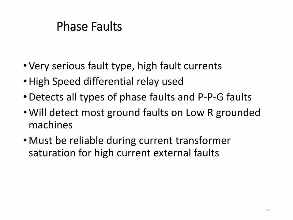
Phase Faults
•Very serious fault type, high fault currents
•High Speed differential relay used
•Detects all types of phase faults and P-P-G faults
•Will detect most ground faults on Low R grounded machines
•Must be reliable during current transformer saturation for high current external faults
47

Phase Fault Protection
•Variable % Differential Scheme most widely used (low impedance)
•High Impedance Scheme also available
•High Z grounded units – ground fault current below threshold of relay
•Will not detect a turn – turn fault
48
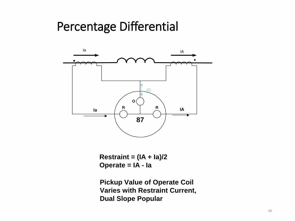
Percentage Differential
87
R R
O
Ia IA
Restraint = (IA + Ia)/2
Operate = IA - Ia
Pickup Value of Operate Coil
Varies with Restraint Current,
Dual Slope Popular
49
IA Ia
IO

Percentage Differential
•External faults create high values of restraint current and desensitize relay to allow for CT saturation
• Internal faults produce minimum values of restraint and sensitive tripping
•CFD Delay of 20-40 ms. (Old electro-mecchanical relay)
•Setting of 0.2 amps secondary current, varies with restraint current
50

Phase Fault Backup
• Large Units often use backup protection
•Unit Connected generators use overall differential scheme
•Overall Differential covers generator, bus, step up transformer, and unit auxiliary transformer
•Harmonic Restraint required due to transformer coverage in protection zone
•Distance Relay (21) with CT in neutral
51

Overall Differential – 87/U
Z
Auxiliary Load
Po
we
r S
ys
tem
Unit Connected Generator
87O
52
Field Ground Protection

Field Ground Protection (64F)
•Field Circuit Insulated from Ground
•One Ground on field does not effect operation of generator
•A Second Ground on the field will short a portion of the field winding
•Unbalanced air gap fluxes will cause vibration and quickly damage unit
•Detection of first ground essential
54
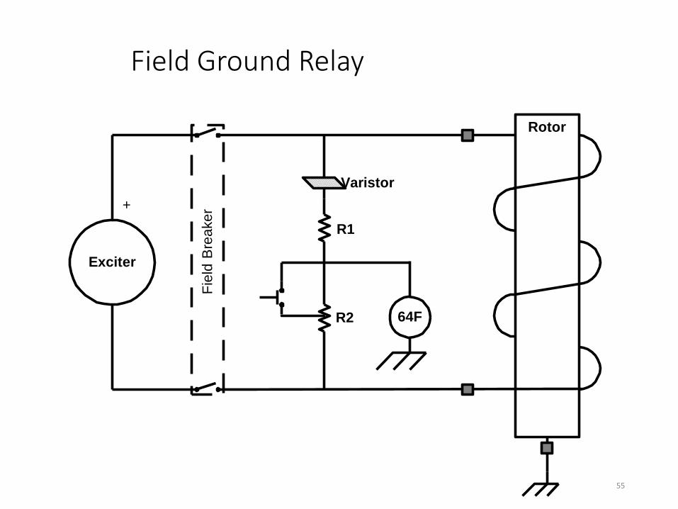
Field Ground Relay
Exciter
Rotor
+
64F
Fie
ld B
rea
ke
r
R1
R2
Varistor
55
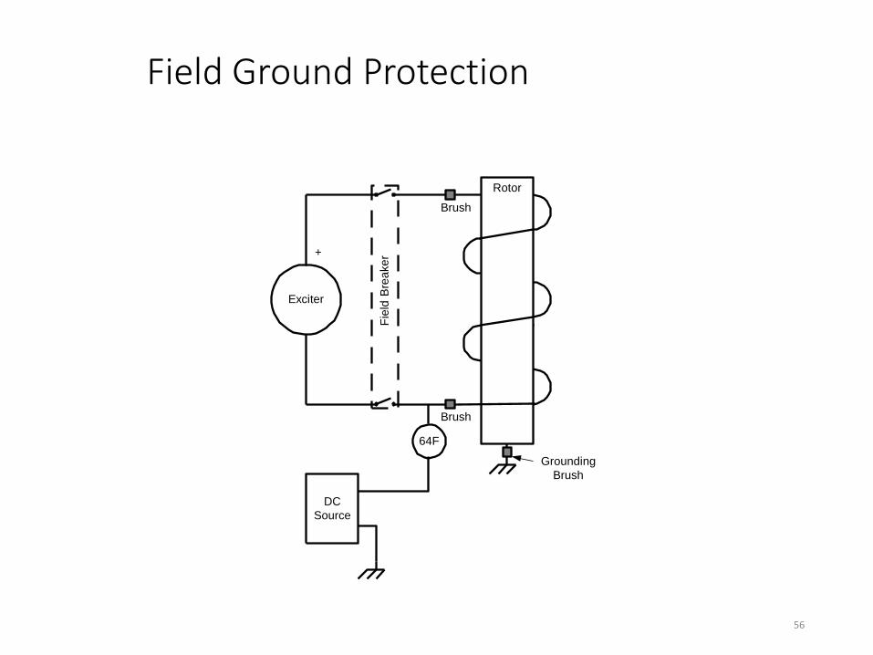
Field Ground Protection
Exciter
Rotor
+
DC
Source
64F
Fie
ld B
rea
ke
r
Grounding
Brush
Brush
Brush
56
Brushless Machines
•Conventional Relays do not work
•Add Pilot Brushes to connect to rotating field circuit
•Momentary brush connection used to avoid wear and dusting
•Bridge circuit used to detect shorted winding capacitance to ground
•Can be manual or automatic
57

Pilot Brushes
Exciter
Rotor
+
64F
Fie
ld B
rea
ke
r
AC
Source
R
R
C2C1 CR
Field Ground Shorts
CR, Unbalances
Bridge
Pilot
Brush
Pilot Brush is periodicly put in contact with Field Circuit 58
Voltage Signal Injection
• Inject a low frequency signal between field winding and ground
•Measurement of resistance to ground can detect insulation deterioration or short circuit
•Measures insulation levels in real time
•Can provide warning of low resistance prior to field ground relay operation
59

Injection Scheme
Exciter
Rotor
+
Fie
ld B
rea
ke
r
C
Squarewave
Generator
Measuring
Unit
Injected
Signal
Signal
Return
R
R
RC
Coupling Network
60
• Amplitude of Return Signal depends on Rotor Leakage R
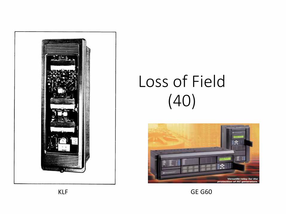
Loss of Field (40)
KLF GE G60

Loss of Field (40)
• LOF Detrimental to System and Generator
• LOF Condition should be quickly detected and the unit tripped
•Generator will speed up and operate as an induction generator w/o field current
•Reactive power drawn from the system will depress system voltage
62

Loss of Field Effects
• Low system voltage/collapse
•High rotor surface temp due to slip
•Stator temperature increases due to high current (up to 2 pu. If operating at full load)
63

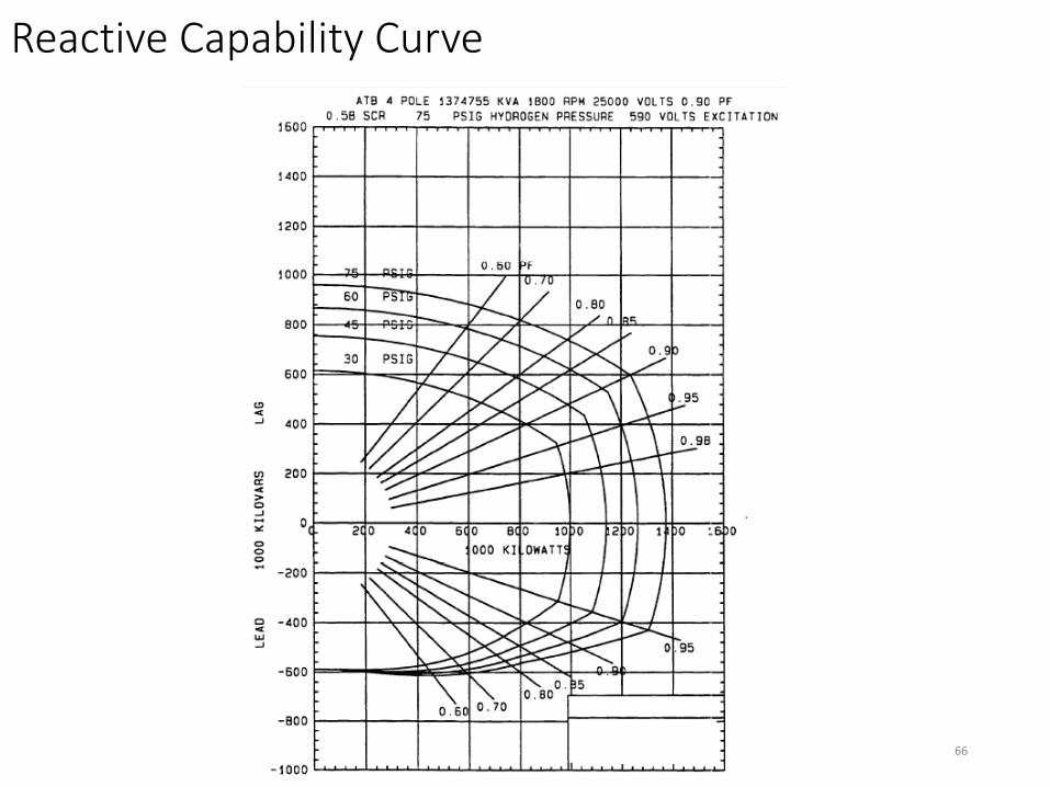
Loss of Field Protection
• Large machines use impedance relay(s) located on the machine terminals.
• Impedance relays set to coordinate protection with minimum excitation limiter, steady state stability limit, and machine capability curve
64
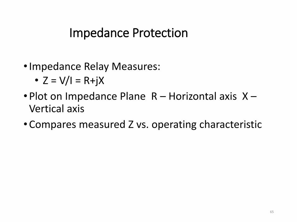
Impedance Protection
• Impedance Relay Measures: • Z = V/I = R+jX
•Plot on Impedance Plane R – Horizontal axis X – Vertical axis
•Compares measured Z vs. operating characteristic
65
66
Reactive Capability Curve
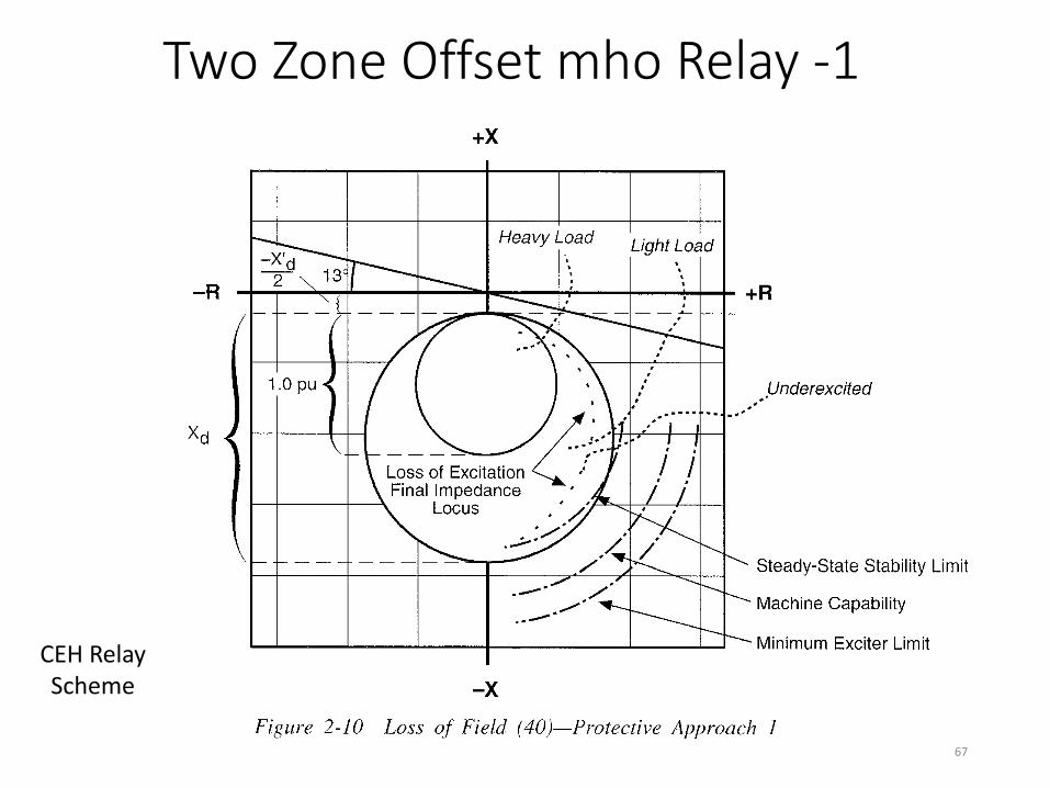
Two Zone Offset mho Relay -1
67
CEH Relay Scheme
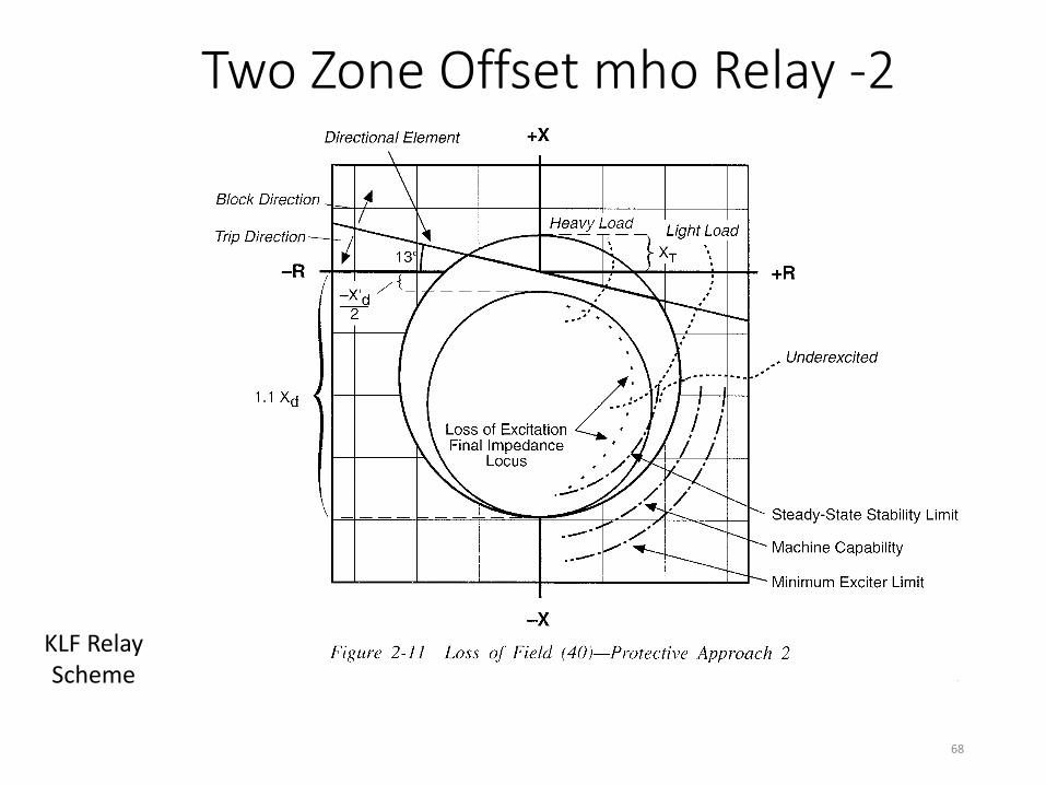
Two Zone Offset mho Relay -2
68
KLF Relay Scheme

69 -900
-800
-700
-600
-500
-400
-300
-200
-100
0
100
-100 0 100 200 300 400 500 600 700 800 900 1000 1100 1200 1300 1400 1500 1600 1700
Q (MVAR)
P (MW)
Loss of Field Coordination P-Q Plane
GCC
SSSL 3L
LOF1
LOF11
MEL
Max MW
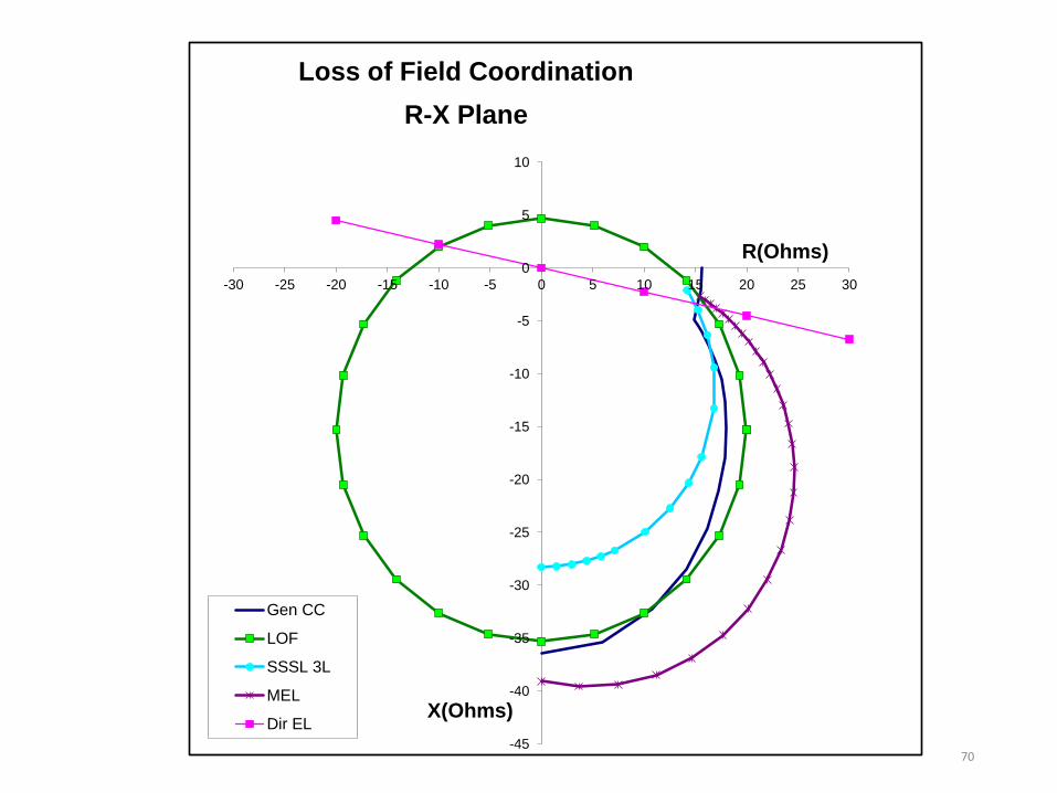
70 -45
-40
-35
-30
-25
-20
-15
-10
-5
0
5
10
-30 -25 -20 -15 -10 -5 0 5 10 15 20 25 30
X(Ohms)
R(Ohms)
Loss of Field Coordination
R-X Plane
Gen CC
LOF
SSSL 3L
MEL
Dir EL

Unbalanced Current (46)

Unbalanced Currents
• Unbalanced load currents, Negative Sequence, induce double frequency current in the rotor surface
• Induced rotor currents cause rapid heating of rotor surface, retaining rings, slot wedges and possibly the field winding
• Can be caused by unbalanced load, open phases, system faults
72
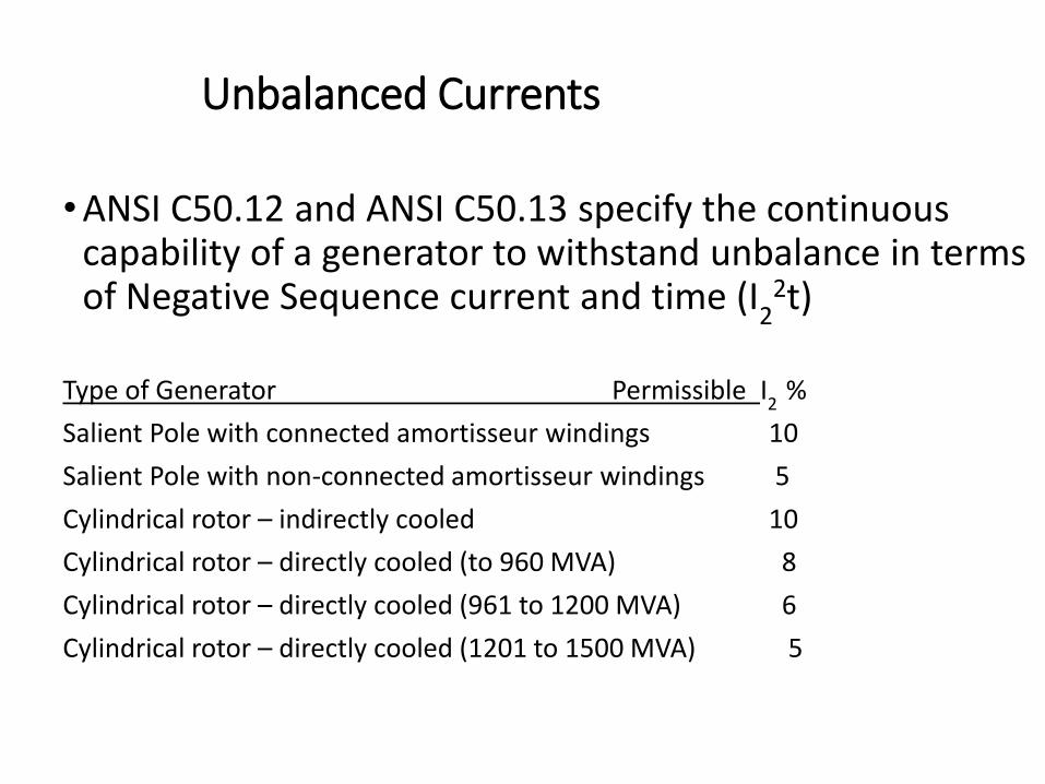
Unbalanced Currents
•ANSI C50.12 and ANSI C50.13 specify the continuous capability of a generator to withstand unbalance in terms of Negative Sequence current and time (I
22t)
Type of Generator Permissible I
2 %
Salient Pole with connected amortisseur windings 10
Salient Pole with non-connected amortisseur windings 5
Cylindrical rotor – indirectly cooled 10
Cylindrical rotor – directly cooled (to 960 MVA) 8
Cylindrical rotor – directly cooled (961 to 1200 MVA) 6
Cylindrical rotor – directly cooled (1201 to 1500 MVA) 5

Unbalanced Currents
• Thermal capability expressed in terms of per unit rated current and time
(I2
2t) Type of Generator Permissible (I
22t)
Salient Pole 40
Synchronous Condenser 30
Cylindrical Rotor
Indirectly Cooled 30
Directly Cooled (0 – 800 MVA) 10
Directly Cooled (801 - 1600 MVA) Per Curve*
74
* I2
2t = 10 – 0.00625(MVA-800)
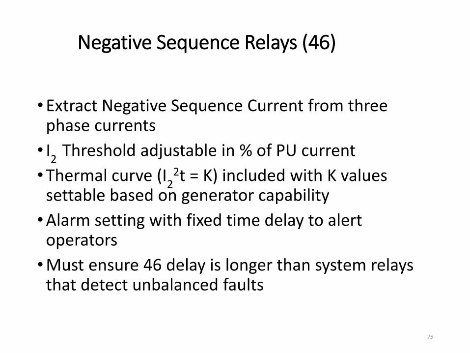
Negative Sequence Relays (46)
•Extract Negative Sequence Current from three phase currents
• I2
Threshold adjustable in % of PU current
•Thermal curve (I2
2t = K) included with K values settable based on generator capability
•Alarm setting with fixed time delay to alert operators
•Must ensure 46 delay is longer than system relays that detect unbalanced faults
75

46 Time Curves
76

Reverse Power (32)

Reverse Power (32)
•Motoring caused when energy to prime mover is lost (i.e.: turbine trip)
•Generator is driven by system as a synchronous motor which drives the prime mover
•Prime mover components can be damaged by motoring ( turbine blade heating, turbine gears, un-ignited diesel fuel in exhaust)
78

Reverse Power
• Level of reverse power depends on prime mover
•Diesel Engines – 5-25%
•Hydro Turbines – 0.2 to 2% (dry)
•Steam Turbines – 0.5 to 3%
•High level of reactive power flow with small level of reverse power
• Low Forward Power flow, (Under power) is an alternative scheme
79

Reverse Power (32)
P
Q
TRIP1 PU-1 PU
Pickup
Reverse
Power FlowForward
Power Flow
Reverse Power
Relay
Characteristics80

Overexcitation (24)

Over Excitation
•Generators rated for 5% overvoltage at rated frequency
•Transformers rated for 10% overvoltage at no load, 5% at full load 80%PF
•V/Hz used to determine level of core flux
•Saturation of magnetic core result of V/Hz ratios above 1.05 pu
•During saturation flux flows outside of core
82

Over Excitation
•Thermal problems occur if level is not reduced
•Protection based on V/Hz vs. time curves for Generator and Transformer
• Inverse time V/Hz relay used to model equipment capability curves
•Definite time units used for alarm and fast tripping at maximum level
83

Overexcitation Protection
Overexcitation Curves
90.0
95.0
100.0
105.0
110.0
115.0
120.0
125.0
130.0
135.0
140.0
145.0
150.0
0.01 0.10 1.00 10.00 100.00
Time (min)
Vo
lts/H
z (
%)
84
Generator
Transformer
Alarm
Relay

Overvoltage (59)
•Excess voltage can damage insulation
•V/Hz uses ratio of voltage to frequency and may not detect overvoltage at higher than nominal frequency
•Causes include over speed after load rejection (Hydro Units)
•Not useful as V/Hz protection, may provide limited backup
85

Abnormal Frequency Protection (81O/U)
•Generator and Turbine have operational frequency limitations •Generators:
• Mechanical components aging • Thermal considerations
• Turbines: • Blade fatigue • Blade resonant frequencies • Turbine limitations are more restrictive than generators
86

Generator/Transformer
•Transformer/Generator Overexcitation due to low frequency operation
•Reduced ventilation at reduced frequencies reduces KVA capability
• IEC 34-3 limits operational range to ±2% continuous or +3/-5% short durations
•Mechanical resonances can be excited
•Double frequency resonances excited by Negative Sequence current
87

IEC 34-3
88
Generator Operation over ranges of voltage and frequency
Time Restricted Operating Zone
Continuous Operation
57 Hz 61.8 Hz
Turbine
•Blade fatigue is cumulative and non-reversible
•Blades designed with resonance frequencies displaced from 60Hz harmonics
•Off frequency operation may excite the resonance
•Turbine manufacturers provide operating limits vs. frequency
89

90
Frequency Protection 81O/U
•System load shedding should operate to prevent operation in prohibited regions
•Underfrequency tripping should coordinate with system load shedding plans of Regional Coordinating Council (RCC) and turbine limitations
•Unnecessary tripping can cause system collapse during overload conditions
•RCC may require load shedding that is equal to MVA of unit tripped
91
Frequency Protection 81O/U
•Modern digital relays have multiple steps of protection available
•Settings should allow for expected system frequency drop and recovery based on load shedding plans
•Trip time delays should be allow for system recovery time
•Over frequency settings should coordinate with governor response time
92

93
Coordination
• Coordination is necessary to ensure that the UFLS program can operate to restore a balance between generation and load to stabilize frequency at a sustainable operating condition.
• The UFLS program always should be allowed to take action well before tripping a generating unit for turbine protection.
Out of Step Protection(78)
94
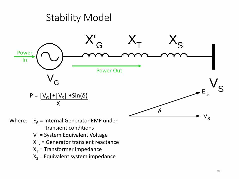
Stability Model
VG V
S
X'G
XT
XS
EG
VS
95
Where: EG = Internal Generator EMF under transient conditions VS = System Equivalent Voltage X’G = Generator transient reactance XT = Transformer impedance XS = Equivalent system impedance
Power Out
P = |VG|•|VS| •Sin(δ) X
Power In
Loss of Synchronism
• In a steady state condition the Power Angle (δ) is constant
•A disturbance in power flow will cause an oscillation of the angle δ around a new operating point
• If the disturbance is to large, δ will continue to increase & machine is operating at a different frequency than system
•Unit is now out of Synchronism
96
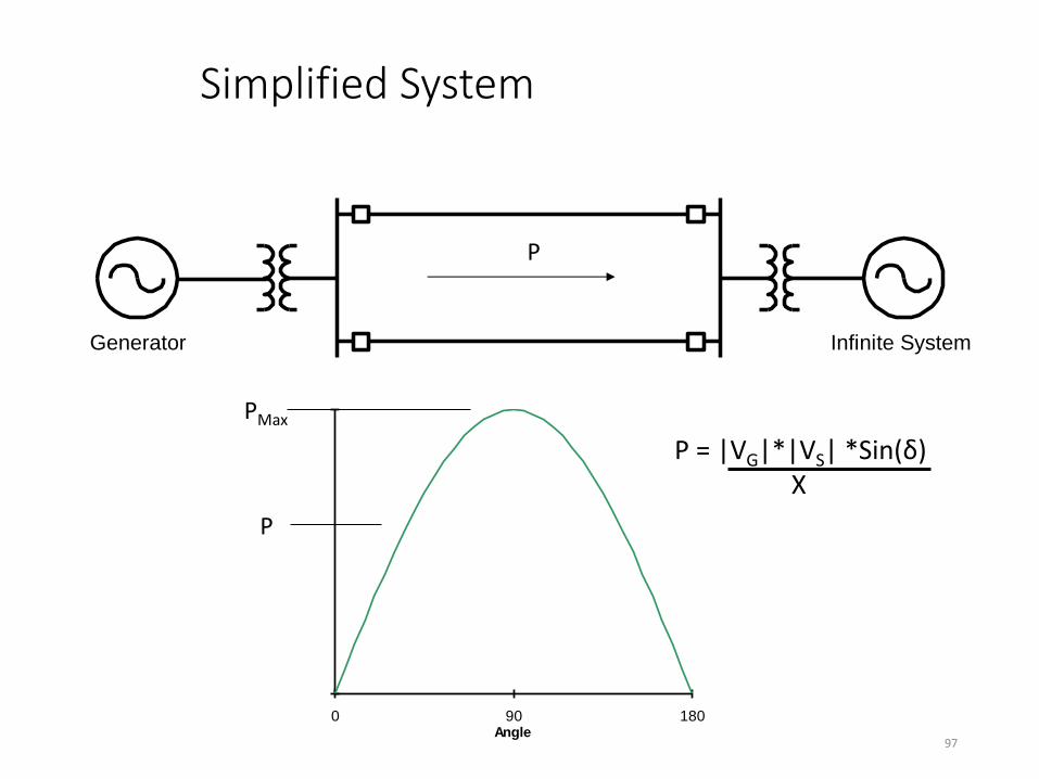
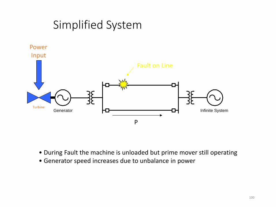
Simplified System
Generator Infinite System
0 90 180Angle
97
PMax
P
P
P = |VG|*|VS| *Sin(δ) X

Simplified System
Generator Infinite System
0 90 180Angle
98
PMax
P
P
1 Line
2 Lines
Fault Effects
•During a fault the generator rotor angle advances, 3 phase fault is worst case
•3 phase fault near generator results in maximum acceleration of generator, voltage approximately zero
•Prime mover accelerates rotor
•Clearing Time becomes the critical parameter for stability
99
Simplified System
Generator Infinite System
100
P
Fault on Line
• During Fault the machine is unloaded but prime mover still operating • Generator speed increases due to unbalance in power
Power Input
Turbine
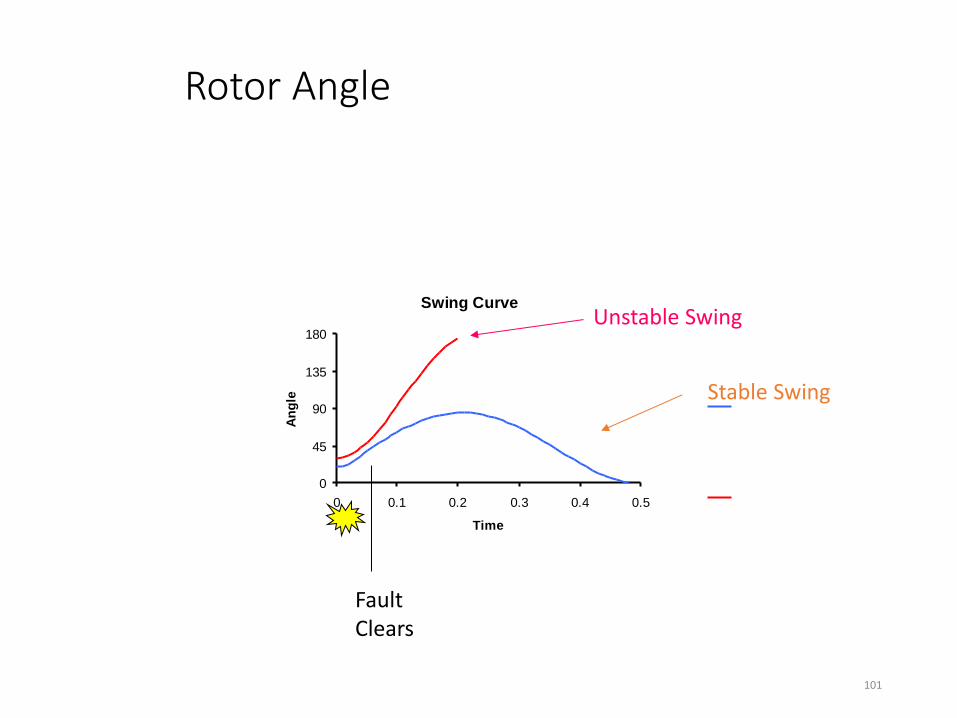
Rotor Angle
Swing Curve
0
45
90
135
180
0 0.1 0.2 0.3 0.4 0.5
Time
An
gle
101
Fault Clears
Unstable Swing
Stable Swing

Equal Area Criteria
0 90 180Angle
102
P
Trip Fault
Max. Angle
Final Operating Point
Two Lines
One Line
During Fault
Generator Acceleration
Generator Deceleration
A1
A2
Out of Step Relay (78)
•Relay should distinguish between stable and unstable swings
•Single blinder 78 scheme provides discrimination between stable and unstable swings
•Multiple other schemes also available
103
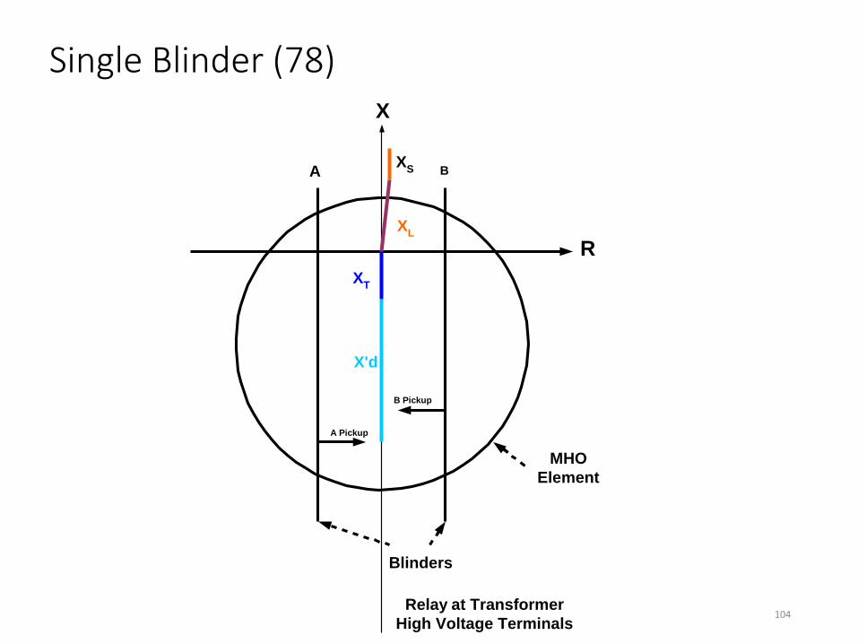
Single Blinder (78)
R
X
MHO
Element
Blinders
A B
A Pickup
B Pickup
X'd
XT
XL
XS
Relay at Transformer
High Voltage Terminals104

Single Blinder (78)
R
X
A B
X'd
XT
XL
XS
δ
105
δ = Power Angle Set δ ≈ 120º to calculate blinders
Single Blinder (78)
R
X
A B
X'd
XT
XL
XS
123456
106
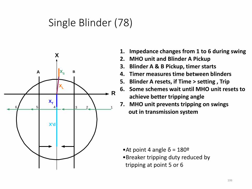
1. Impedance changes from 1 to 6 during swing 2. MHO unit and Blinder A Pickup 3. Blinder A & B Pickup, timer starts 4. Timer measures time between blinders 5. Blinder A resets, if Time > setting , Trip 6. Some schemes wait until MHO unit resets to
achieve better tripping angle 7. MHO unit prevents tripping on swings out in transmission system
•At point 4 angle δ = 180º •Breaker tripping duty reduced by tripping at point 5 or 6

Single Blinder (78)
R
X
A B
X'd
XT
XL
XS
δ
107
δ = Power Angle
Swing Locus
Unstable
Stable

Out of Step
•High levels of transient shaft torque are developed during swings
• If resonant frequency of shaft ≈ slip frequency, the shaft can be damaged
•High peak currents cause stator overheating
•Generator should be tripped during
first slip cycle
108
System Backup Protection (21) or (51V)
109

System Backup Protection
•Protect against failure of system relays
•Time delayed protection for Phase and Ground Faults
•Must have enough sensitivity to detect system faults
•Coordination with system relays essential for security of scheme
•Secure for load and stable swings
110

Phase Backup Protection
•Use Phase Distance relay (21) when coordinating with distance type system relays.
•Use Voltage Controlled/Restrained (51V) Overcurrent relay when coordinating with feeder overcurrent relays (smaller units)
111
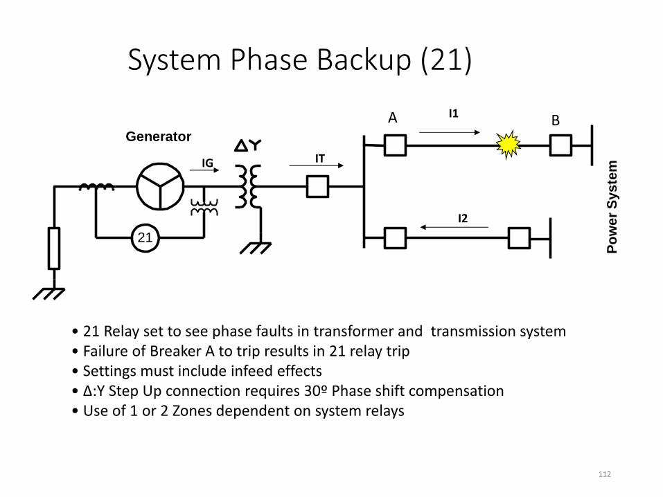
System Phase Backup (21)
Generator
Po
we
r S
ys
tem
21
112
A B
IG IT
I1
I2
• 21 Relay set to see phase faults in transformer and transmission system • Failure of Breaker A to trip results in 21 relay trip • Settings must include infeed effects • Δ:Y Step Up connection requires 30º Phase shift compensation • Use of 1 or 2 Zones dependent on system relays
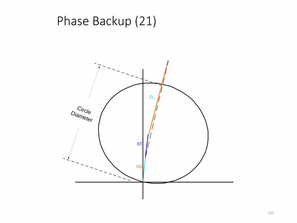
Phase Backup (21)
XG
XT
ZL
CircleDiameter
113
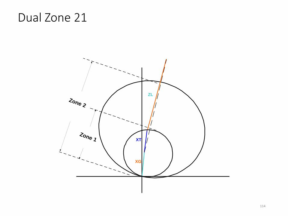
Dual Zone 21
XG
XT
ZL
Zone 2
Zone 1
114

Protected Zones (21)
Generator
Po
we
r S
ys
tem
21
115
Zone 1
Zone 2

Loadability Concerns
•21 relay reach can encroach on load region.
•Reach must be reduced in operating region to allow max output from generator
116

117 -10
-5
0
5
10
15
20
-15 -10 -5 0 5 10 15 20
X(Ohms)
R(Ohms)
21 Relay Loadability Plot
1PU Ohms
MTA
P Dist
+ PF
-PF
Center
Max MVA
NERC 1
NERC 2
Rated MVA
NERC
PF Line
NERC Method 1 & 2 Limits

System Ground Fault Backup
• Unit connected generators use ground relay in step up transformer neutral
• Direct connected generators use a overcurrent relay in the generator neutral
• Set above system relays with time coordination
118

Ground Fault Backup (451N/T)
Generator
Po
we
r Sy
ste
m
51N
119
• Set above the settings of the system relays • Time coordination used to ensure primary and backup system relays trip first

Multi-function Relays
120
SEL 300G Beckwith M-3425A
Majority of required protection in one box
GE G60
ABB GPU2000R
Basler GPS100

One Line
121 Reprinted from Beckwith M-3425 Instruction Book
• Complete unit protection • Adaptable for High or Low R grounding • Must consider how to provide backup protection • Reduces wiring and panel costs
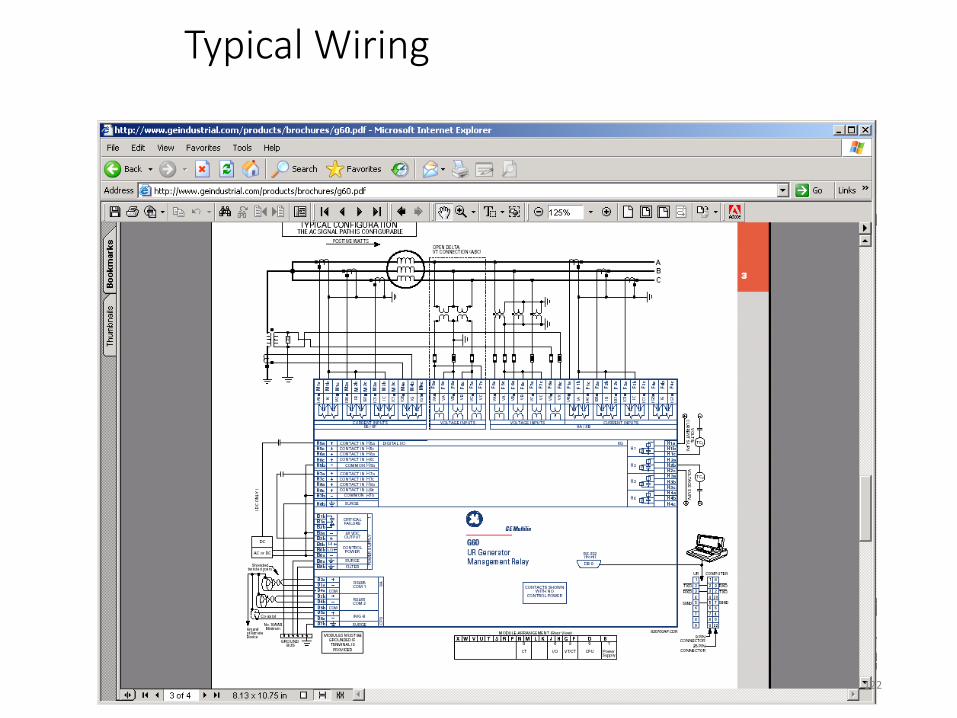
Typical Wiring
122
References
•C37.102 - Guide for AC Generator Protection
•C37.101 - Guide for Generator Ground Protection
•C37.106 - Guide for Abnormal Frequency Protection of Power Generating Plants
• IEEE Tutorial on the Protection of Synchronous Generators
•Power Plant and Transmission System Protection Coordination , NERC Technical Reference Document, Dec 2009
•NERC Standards PRC-019. PRC-024, PRC-025. PRC-026
123

The End
124