Fundamentals for Remote Structural Health Monitoring of...
47
General rights Copyright and moral rights for the publications made accessible in the public portal are retained by the authors and/or other copyright owners and it is a condition of accessing publications that users recognise and abide by the legal requirements associated with these rights. • Users may download and print one copy of any publication from the public portal for the purpose of private study or research. • You may not further distribute the material or use it for any profit-making activity or commercial gain • You may freely distribute the URL identifying the publication in the public portal If you believe that this document breaches copyright please contact us providing details, and we will remove access to the work immediately and investigate your claim. Downloaded from orbit.dtu.dk on: Jun 22, 2018 Fundamentals for remote structural health monitoring of wind turbine blades - a preproject. Annex B. Sensors and non-destructive testing methods for damage detection in wind turbine blades Lading, Lars; McGugan, Malcolm; Sendrup, P.; Rheinländer, J.; Rusborg, J. Publication date: 2002 Document Version Publisher's PDF, also known as Version of record Link back to DTU Orbit Citation (APA): Lading, L., McGugan, M., Sendrup, P., Rheinländer, J., & Rusborg, J. (2002). Fundamentals for remote structural health monitoring of wind turbine blades - a preproject. Annex B. Sensors and non-destructive testing methods for damage detection in wind turbine blades. (Denmark. Forskningscenter Risoe. Risoe-R; No. 1341(EN)).
Transcript of Fundamentals for Remote Structural Health Monitoring of...
General rights Copyright and moral rights for the publications made accessible in the public portal are retained by the authors and/or other copyright owners and it is a condition of accessing publications that users recognise and abide by the legal requirements associated with these rights.
• Users may download and print one copy of any publication from the public portal for the purpose of private study or research. • You may not further distribute the material or use it for any profit-making activity or commercial gain • You may freely distribute the URL identifying the publication in the public portal
If you believe that this document breaches copyright please contact us providing details, and we will remove access to the work immediately and investigate your claim.
Downloaded from orbit.dtu.dk on: Jun 22, 2018
Fundamentals for remote structural health monitoring of wind turbine blades - apreproject. Annex B. Sensors and non-destructive testing methods for damagedetection in wind turbine blades
Lading, Lars; McGugan, Malcolm; Sendrup, P.; Rheinländer, J.; Rusborg, J.
Publication date:2002
Document VersionPublisher's PDF, also known as Version of record
Link back to DTU Orbit
Citation (APA):Lading, L., McGugan, M., Sendrup, P., Rheinländer, J., & Rusborg, J. (2002). Fundamentals for remotestructural health monitoring of wind turbine blades - a preproject. Annex B. Sensors and non-destructive testingmethods for damage detection in wind turbine blades. (Denmark. Forskningscenter Risoe. Risoe-R; No.1341(EN)).

Risø-R-1341(EN)
Fundamentals for Remote Structural Health Monitoring of Wind Turbine Blades – a Preproject Annex B – Sensors and Non-Destructive Testing Methods for Damage Detection in Wind Turbine Blades Lars Lading, Malcolm McGugan, Peder Sendrup, Jørgen Rheinländer and Jens Rusborg
Risø National Laboratory, Roskilde, Denmark May 2002

Risø-R-1341(EN)
Fundamentals for Remote Structural Health Monitoring of Wind Turbine Blades - a Preproject Annex B - Sensors and Non-Destructive Testing Methods for Damage Detection in Wind Turbine Blades Lars Lading, Sensor Technology Center Malcolm McGugan, Risø National Laboratory Peder Sendrup, DELTA Jørgen Rheinländer, InnospeXion Jens Rusborg, FORCE Technology
Risø National Laboratory, Roskilde May 2002
Abstract This annex provides a description of the sensor schemes and the non-destructive testing (NDT) methods that have been investigated in this project. Acoustic emission and fibre optic sensors are described in some detail whereas only the key features of well-established NDT methods are presented. Estimates of the cost of different sensor systems are given and the advantages and disad-vantages of the different schemes is discussed.
ISBN 87-550-3056-4 ISBN 87-550-3057-2 (Internet) ISSN 0106-2840
Print: Pitney Bowes Management Services Denmark A/S, 2002

3 Risø-R-1341(EN)
Contents
Preface 4
1 The basis of Acoustic Emission monitoring in Polymer Matrix Composites 5 1.1 Introduction 5 1.2 Sensing Acoustic Emission 5 1.3 Interpreting the waveform 6 1.4 Acoustic emission in polymer matrix composites 6 1.5 Zonal and time of flight localisation of the stress wave source 7 1.6 Mounting sensors 8 1.7 Alternative sensor types 9 1.8 The Kaiser effect and its exceptions 10 1.9 Problems and questions for a stress wave based monitoring system 11 1.10 Detecting stress wave emission in wind turbine blades 11 1.11 The Can-bus system, integrated sensors and advanced information display 12 1.12 A Structural Health Monitoring System based on Acoustic Emission 13 1.13 Fabrication issues and sensor distribution 13 1.14 Sensor adaptation 15 1.15 Advanced analysis 16 1.16 Final words 17 1.17 References 18
2 Fiber optic sensors for strain and displacement measurements 19 2.1 Basic principles 19 2.2 Survey of fiber optic sensing methods 20 2.3 Evaluation 21 2.4 A Bragg grating sensor set-up 23 2.5 References 26
3 Inertial sensing 30
4 Real-time X-ray Inspection 32 4.1 Methodology 32 4.2 Objectives 33 4.3 Detection Capabilities 33 4.4 Work Accomplished 34
5 Ultrasound inspection 36 5.1 Detection of delaminations and cracks in adhesions 36 5.2 Detection of fibre rupture and transverse cracks through laminate 37 5.3 Field applicability 37
6 Optical Coherence Tomography 39
7 Comparing Sensors for Damage Detection in Wind Turbine Blades 41

4 Risø-R-1341(EN)
Preface This report is Annex B of the reports of the pre-project "Grundlag for fjernovervågning af vindmøllevingers tilstand (Fase I: Forprojekt)", supported by PSO-funding through Elkraft System, contract no. Bro-91.055, FU nr. 1102. The project was performed within 12 month 2001-2002 in collaboration be-tween Risø National Laboratory (project leader), DELTA, Sensor Technology Center A/S, Force Technology, InnospeXion and LM Glasfiber. The project is reported in a summary-report and in some Annexes (A-F).
The title of the summary report is: "Fundamentals for remote structural health monitoring of wind turbine blades - a pre-project", Bent F. Sørensen, Lars Lading, Peter Sendrup, Malcolm McGugan, Christian P. Debel, Ole J. D. Kristensen, Gunner Larsen, Anders M. Hansen, Jørgen Rheinländer, Jens Rusborg and Jørgen D. Vestergaard, Risø-R-1336(EN), May 2002. The titles of the annexes are: Annex A: "Fundamentals for Remote Structural Health Monitoring of Wind Turbine Blades – a Preproject. Annex A - Cost benefit for embedded sensors in wind turbine blades", Lars Gottlieb Hansen and Lars Lading, Risø-R-1340(EN), Risø National Laboratory, Roskilde, Denmark, May 2002. Annex B: "Fundamentals for Remote Structural Health Monitoring of Wind Turbine Blades – a Preproject. Annex B - Sensors and non-destructive testing methods for damage detection in wind turbine blades", Lars Lading, Malcolm McGugan, Peter Sendrup, Jørgen Rheinländer and Jens Rusborg, Risø-R-1341(EN), Risø National Laboratory, Roskilde, Denmark, May 2002. Annex C: "Fundamentals for Remote Structural Health Monitoring of Wind Turbine Blades – a Preproject. Annex C - Fibre transducer for damage detection in adhesive layers of wind turbine blades", Peter Sendrup, Risø-R-1342(EN), Risø National Laboratory, Roskilde, Denmark, May 2002. Annex D: "Fundamentals for Remote Structural Health Monitoring of Wind Turbine Blades – a Preproject. Annex D - Laboratory tests using condition monitoring sensors", Malcolm McGugan, Risø-I-1878(EN), Risø National Laboratory, Roskilde, Denmark, May 2002. Annex E: "Fundamentals for Remote Structural Health Monitoring of Wind Turbine Blades – a Preproject. Annex E - Full-scale testing of wind turbine blade", Ole J. D. Kristensen, Malcolm McGugan, Peter Sendrup, Jørgen Rheinländer, Jens Rusborg, Bent F. Sørensen, Christian P. Debel and Anders M. Hansen, Risø-R1333(EN), Risø National Laboratory, Roskilde, Denmark, May 2002. Annex F: "Identification of damage to wind turbine blades by modal parameter estimation", Gunner Larsen, Anders M. Hansen and Ole J. D. Kristensen, Risø-R-1334(EN) Risø National Laboratory, Roskilde, Denmark, April 2002.
Risø-R-1341(EN) 5
1 The basis of Acoustic Emission monitoring in Polymer Matrix Com-posites Malcolm McGugan, Risø National Laboratory
1.1 Introduction Here, the general process of detecting stress wave emission in polymer matrix composites is described. There follows some initial work detailing the applica-tion of such a detection system on a wind turbine blade. A proposed architecture is chosen and its advantages and disadvantages are discussed. Likely advances in sensor type, analysis technique and display modes are put forward as they relate to the topic of structural monitoring and repair of large and remote com-posite structures.
1.2 Sensing Acoustic Emission When certain dynamic processes occur rapidly in or on the surface of a material some of the energy which is released generates elastic stress waves; we might say vibrations within the material. These stress waves propagate from the source and eventually reach the surface, so producing small temporary surface dis-placements. In most cases the stress waves are of too low an amplitude and/or too high a frequency to be audible. However, sensitive transducers can detect the very small surface accelerations produced by the waves. As generally the signal does not fall in the human audible range, acoustic emission (AE) is a misnomer and the alternative term stress wave emission (SWE) is a more accu-rate description of the phenomenon, both are used but acoustic emission is the expression in more widespread use.
The most common variety of transducers for AE monitoring are piezoelectric sensors that convert the accelerations at the surface into an electrical signal. Broadband piezoelectric transducers respond to all the frequencies of the stress wave and return a signal which closely replicates the small-scale motion of the surface. Resonant piezoelectric transducers are left undamped and free to "ring" at their resonant frequency (or frequencies). For detecting SWE in large struc-tures, the resonant transducers are more common as they can detect events much further away.
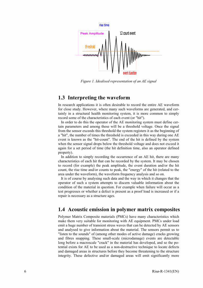
The electrical signal obtained from the transducer is amplified. An idealised signal is shown in Figure 1, such as might be returned from an undamped (reso-nant) piezoelectric crystal transducer as the result of a single surface displace-ment resulting from a micro-damage event (fibre snap or matrix crack).
6 Risø-R-1341(EN)
Figure 1. Idealised representation of an AE signal
1.3 Interpreting the waveform In research applications it is often desirable to record the entire AE waveform for close study. However, where many such waveforms are generated, and cer-tainly in a structural health monitoring system, it is more common to simply record some of the characteristics of each event (or "hit").
In order to do this the operator of the AE monitoring system must define cer-tain parameters and among these will be a threshold voltage. Once the signal from the sensor exceeds this threshold the system registers it as the beginning of a "hit", the number of times the threshold is exceeded in this way during one AE event is known as the "hit-count". The end of the hit is defined by the system when the sensor signal drops below the threshold voltage and does not exceed it again for a set period of time (the hit definition time, also an operator defined property).
In addition to simply recording the occurrence of an AE hit, there are many characteristics of each hit that can be recorded by the system. It may be chosen to record (for example) the peak amplitude, the event duration and/or the hit count, the rise time and/or counts to peak, the "energy" of the hit (related to the area under the waveform), the waveform frequency analysis and so on.
It is of course by analysing such data and the way in which it changes that the operator of such a system attempts to discern valuable information about the condition of the material in question. For example when failure will occur as a test progresses or whether a defect is present as a proof load is increased or if a repair is necessary as a structure ages.
1.4 Acoustic emission in polymer matrix composites Polymer Matrix Composite materials (PMCs) have many characteristics which make them very suitable for monitoring with AE equipment. PMCs under load emit a huge number of transient stress waves that can be detected by AE sensors and analysed to give information about the material. The sensors permit us to "listen to the sounds" of (among other modes of active damage) cracks growing and fibres snapping. These small-scale (microdamage) events are detectable long before a macroscale "crack" in the material has developed, and so the po-tential exists for AE to be used as a non-destructive technique to locate defects and damaged areas in structures before they become threatening to the structure integrity. These defective and/or damaged areas will emit significantly more
Risø-R-1341(EN) 7
under load (that is more frequently and at higher amplitudes) than surrounding "good" material.
The AE sensors also detect the larger stress wave emissions resulting from structurally significant damage events in PMC materials, events such as inter-face failures, delaminations, impacts and adhesive failure. These macro-scale events result also in distinctly different waveforms compared to the micro-scale events. Often much higher amplitudes and, more significantly, longer duration waveform types are observed.
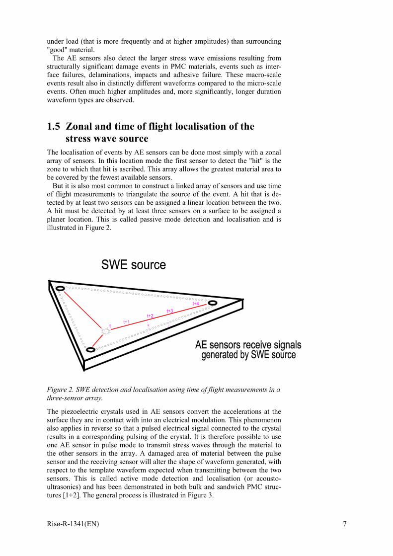
1.5 Zonal and time of flight localisation of the stress wave source
The localisation of events by AE sensors can be done most simply with a zonal array of sensors. In this location mode the first sensor to detect the "hit" is the zone to which that hit is ascribed. This array allows the greatest material area to be covered by the fewest available sensors.
But it is also most common to construct a linked array of sensors and use time of flight measurements to triangulate the source of the event. A hit that is de-tected by at least two sensors can be assigned a linear location between the two. A hit must be detected by at least three sensors on a surface to be assigned a planer location. This is called passive mode detection and localisation and is illustrated in Figure 2.
t+1t
t+2t+3
t+4
Figure 2. SWE detection and localisation using time of flight measurements in a three-sensor array.
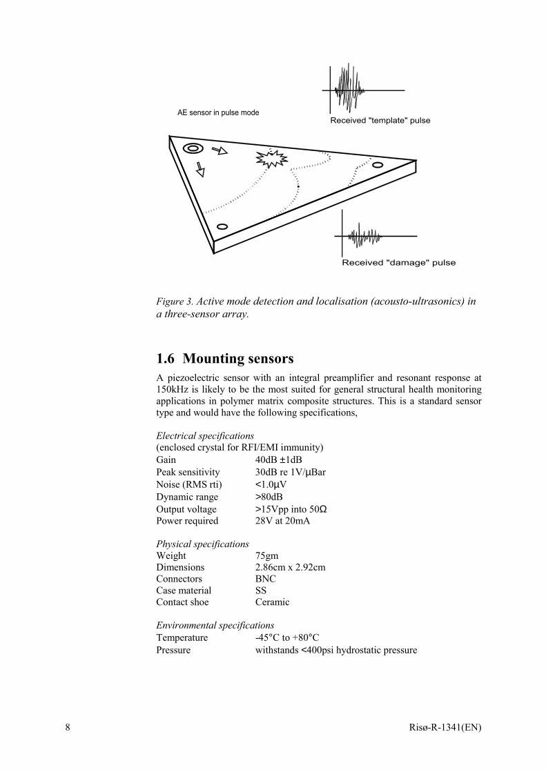
The piezoelectric crystals used in AE sensors convert the accelerations at the surface they are in contact with into an electrical modulation. This phenomenon also applies in reverse so that a pulsed electrical signal connected to the crystal results in a corresponding pulsing of the crystal. It is therefore possible to use one AE sensor in pulse mode to transmit stress waves through the material to the other sensors in the array. A damaged area of material between the pulse sensor and the receiving sensor will alter the shape of waveform generated, with respect to the template waveform expected when transmitting between the two sensors. This is called active mode detection and localisation (or acousto-ultrasonics) and has been demonstrated in both bulk and sandwich PMC struc-tures [1+2]. The general process is illustrated in Figure 3.
8 Risø-R-1341(EN)
Figure 3. Active mode detection and localisation (acousto-ultrasonics) in a three-sensor array.
1.6 Mounting sensors A piezoelectric sensor with an integral preamplifier and resonant response at 150kHz is likely to be the most suited for general structural health monitoring applications in polymer matrix composite structures. This is a standard sensor type and would have the following specifications, Electrical specifications (enclosed crystal for RFI/EMI immunity) Gain 40dB ±1dB Peak sensitivity 30dB re 1V/µBar Noise (RMS rti) <1.0µV Dynamic range >80dB Output voltage >15Vpp into 50Ω Power required 28V at 20mA Physical specifications Weight 75gm Dimensions 2.86cm x 2.92cm Connectors BNC Case material SS Contact shoe Ceramic Environmental specifications Temperature -45°C to +80°C Pressure withstands <400psi hydrostatic pressure
Received "template" pulse
Received "damage" pulse
AE sensor in pulse mode
Risø-R-1341(EN) 9
It is most likely, if it was to be mounted permanently, that the sensor would be protected by a casing. This casing would be bonded to the structure and would hold the sensor tightly against the material surface.
1.7 Alternative sensor types The most common sensor type used in when monitoring stress waves in materi-als is based on a surface mounted piezoelectric crystal. However, there are many other sensors that exist that either use alternative methods for detecting stress wave activity or use piezoelectric materials in different ways. Depending on the application these alternative sensor types may be more attractive than the "traditional" sensor type.
Thin film sensors
Besides the brittle quartz and polycrystal materials, there are also polymers that show piezoelectric effect. Of these, PVDF (Polyvinylidene Fluoride) is an ex-ample of an efficient material for sensors. These materials have the advantages of flexibility, high mechanical strength, dimensional stability, a high and stable piezoelectric coefficient and ease of handling. PVDF can be bonded as a smart layer (25-110µm thick) over composite materials and used as an actuator and a sensor for ultrasonic inspection [3].
Piezoelectric composite materials (PCMs) Piezoelectric composite materials are a new type of functional material combin-ing piezoelectrics with polymers. This gives excellent opportunities for design-ing electrical-mechanical properties into materials. An example would be to use parallel piezoelectric ceramic rods that show orthotropic properties of piezoelectricity embedded into the matrix of a fibre composite. These rods can then be calibrated and used as strain sensors [4].
Rolling sensors
In some automated and moving processes (composite disbond detection, wood product defects, welding, etc.) a rolling stress wave sensor is utilised. This type of sensor has the advantage of needing no couplant, as the compliant tyre makes contact with the moving part being monitored Figure 4 [5].
Optic based sensors
In applications where, for example, electrical wiring is to be avoided, it may be possible to use optical fibre bragg grating lasers as acoustic wave sensors. [6+7].
Embedded piezoelectric sensors Where necessary it is possible to embed piezoelectric transducers within a polymer composite lay up. These transducers (which are 270µm thick) can de-tect and generate stress waves within the material in the same way as the more common surface mounted ones. The advantages of having embedded sen-sors/wiring and therefore a "clean" structure surface must be balanced against possible disadvantages such as accessibility and any effects on the structure properties [8].

10 Risø-R-1341(EN)
Figure 4. Example of a "Rolling" AE sensor
Air coupled transducer Air coupled stress wave transducer exist using laser technology to perform non-contact monitoring [5].
Unidirectional sensors Where only stress waves propagating from one direction are significant it may be possible to use a unidirectional sensor where off-axis signals are rejected [5].
1.8 The Kaiser effect and its exceptions Passive mode AE monitoring responds to the growth of damage and therefore has a fundamental relationship with applied stress, an unloaded structure gener-ally emits very few stress waves. In this respect AE is significantly different from (and complementary to) many other NDT techniques which generally de-tect the presence of defects, rather than the growth of new damage.
It can be stated that when a load is applied to a PMC structure there is AE as the material undergoes some small-scale, permanent deformation at regions of stress concentrations. The Kaiser effect is one of the principal tenants of AE testing and it states that if a structure is unloaded and reloaded again the mate-rial will give no further emission, until the load is taken higher than previously.
The Kaiser effect holds true often, but not universally. This is especially the case with PMC materials which commonly emit at below previous maxima, during unload and even during a steady load period. This is fortunate for those who wish to use AE monitoring to supply through-life health information on PMC structures.
In a PMC structure that experiences a steady load through its lifetime we might expect SWE due to short term changes in environment (such as tempera-ture changes, moisture exposure, wind loading, impact, etc.) and long term changes in material properties due to ageing (such as matrix cracking, water ingress, interface failure, etc.)
A PMC structure that experiences a fatigue load will also emit SWE resulting from the phenomenon listed in the steady load case. In addition we can expect almost constant SWE from damaged areas of the structure due to the rubbing between crack faces and the friable matrix and reinforcement material during fatigue cycling. The AE monitoring system will also be able to identify the ini-tiation and growth of new damage sites.
Risø-R-1341(EN) 11
1.9 Problems and questions for a stress wave based monitoring system
The strongly attenuating effect of PMCs on stress waves travelling through them is in contrast with metallic materials, where stress waves can propagate large distances. The practical effect is that the range of a standard AE sensor is not very great compared to the size of a structural PMC component.
The sensoric range in resonant AE sensors is dependant on the particular resonant frequency of the sensor; because, when propagating through a PMC material, high frequency signals are attenuated more quickly than low frequency signals. That is the low frequency components of a stress wave will propagate further through the material before being attenuated below delectability.
A sensor resonant at 150kHz allows the creation of a zonal localisation array with a sensor spacing of 2m, or a time of flight localisation array with the sen-sors spaced between 0.7-1.0m apart. The frequency of 150kHz is common as this gives a good compromise between noise rejection and sensor spacing. A sensor resonant at 60kHz will allow a much wider spacing but will respond strongly to unwanted "noise" signals, which are commonly low frequency dominated. A sensor resonant at 300kHz might never respond to "noise" sig-nals, but will respond only to AE from failures that occur a matter centimetres from the sensor location.
One aspect of PMC materials is that changes in properties are expected through the lifetime. These changes can be short term (and to some extent re-versible) such as temperature and water exposure, or long term (and generally irreversible) ageing due to material degradation, matrix cracking, interface fail-ure and so on. These changes in properties will also affect the attenuation char-acteristics of PMC material.
There are many different failure modes associated with PMC material, trans-verse cracking, splitting, fibre snapping, fibre pull out, delamination and so on. It is certain that each of these different dynamic failure modes result in different SWE waveform characteristics. It can be proposed that a Structural Health Monitoring System (SHMS) which distinguishes between these failure modes would be very desirable.
The problem here relates to the fact that the waveform received by the sensor depends heavily on the propagation distance. A further complication is due to the anisotropy of PMC materials, the received waveform is also highly depend-ant on the orientation of SWE source, sensor and reinforcement direction. Therefore it may prove to be impossible to distinguish the subtle differences in the source waveform characteristics following propagation through such an at-tenuating and complex material. However larger differences, such as those be-tween micro- and macro-scale events, may be easier to distinguish. In this case failure type identification might best be achieved with source location and a knowledge of the structure design.
In addition to the problems specific to PMCs, there are also those common to any SHMS based on AE monitoring. These include the exclusion of "noise" sources from the record and the identification of the correct data handling pro-cedure in the face of so much potentially recordable information.
1.10 Detecting stress wave emission in wind tur-bine blades
The goal of the main report "Fundamentals for remote structural health monitor-ing of wind turbine blades - a pre-project", of which this document is an annex
12 Risø-R-1341(EN)
(Annex B), investigates the possibility of using structural health monitoring sensors on large, offshore wind turbine blades. Establishing the technical details of such a systems architecture is beyond the scope of this initial investigation. However, it may be germane to describe systems that exist presently and con-sider their advantages and disadvantages as well as possible future develop-ments. In this way the scale of the challenges facing future work can, to some extent, be determined. In this section of the annex a Can-bus system architecture is proposed here as one which may be considered in future work as a possible template for a structural health monitoring system in wind turbine blades.
1.11 The Can-bus system, integrated sensors and advanced information display
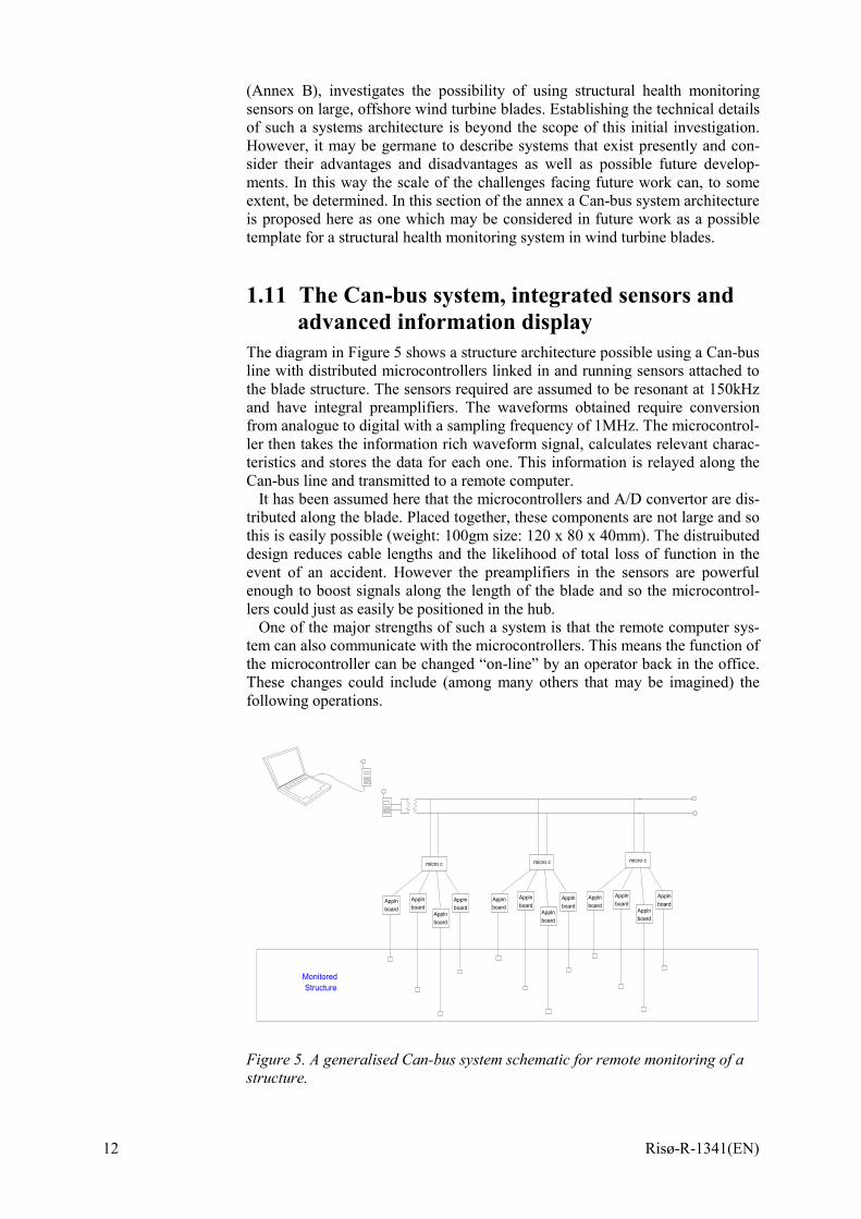
The diagram in Figure 5 shows a structure architecture possible using a Can-bus line with distributed microcontrollers linked in and running sensors attached to the blade structure. The sensors required are assumed to be resonant at 150kHz and have integral preamplifiers. The waveforms obtained require conversion from analogue to digital with a sampling frequency of 1MHz. The microcontrol-ler then takes the information rich waveform signal, calculates relevant charac-teristics and stores the data for each one. This information is relayed along the Can-bus line and transmitted to a remote computer.
It has been assumed here that the microcontrollers and A/D convertor are dis-tributed along the blade. Placed together, these components are not large and so this is easily possible (weight: 100gm size: 120 x 80 x 40mm). The distruibuted design reduces cable lengths and the likelihood of total loss of function in the event of an accident. However the preamplifiers in the sensors are powerful enough to boost signals along the length of the blade and so the microcontrol-lers could just as easily be positioned in the hub.
One of the major strengths of such a system is that the remote computer sys-tem can also communicate with the microcontrollers. This means the function of the microcontroller can be changed “on-line” by an operator back in the office. These changes could include (among many others that may be imagined) the following operations.
micro c
Applnboard
Applnboard
Applnboard
Applnboard
micro c
Applnboard
Applnboard
Applnboard
Applnboard
micro c
Applnboard
Applnboard
Applnboard
Applnboard
MonitoredStructure
Figure 5. A generalised Can-bus system schematic for remote monitoring of a structure.

Risø-R-1341(EN) 13
1.12 A Structural Health Monitoring System based on Acoustic Emission
A SHMS could be implemented as shown in Figure 5. We envisage 20 trans-ducers in order to comply with the required 1 m spatial resolution. The AE transducers are glued to the inside of the glass fiber shell. Each transducer is fitted with a dedicated digital signal processor, which incorporates an analog to digital converter. A microcontroller collects and transmits data from up to 16 transducers. A cost estimate for this set-up is given in section 7.
• Increasing sensitivity until ambient noise signals are detected by the sensors, this would be a form of systems check.
• Altering the waveform characteristic set that is recorded. • Installing entirely new waveform transformations or operations. • Increasing update speed during extreme weather. • Using a sensor in “pulse mode” for active sensing. • Requesting entire waveform samples for analysis.
The Can-bus line and microcontollers are also available for other sensors and functions of the blade. These could include de-icing functions, accelorometer signals, strain readings, temperature readouts and motor functions. Again the limit is only imagination and the systems present on a future structure.
It is also worth including the observation that the entire suite of functions pre-sent would also be available to on-site inspection teams. An operator could use a laptop computer to communicate directly with the blade structure he wishes to examine and get real time information to speed up inspection times and defect diagnosis.
Such a system has the potential to significantly reduce inspection effort where large numbers of structures are involved. It is also likely that an inspector with such a system could be more rapidly trained to a point where they were compe-tent for independent off site inspection than is currently the case.
Further enhancements possible for future offshore inspectors interacting with advanced, "smart" wind turbine structures include the use of AR (Augmented Reality) displays to create an intuitive and immediate view of the structure, its defects and their repair strategies. Smart structures and augmented reality dis-plays are likely to become increasingly common within the next twenty years. Basic systems exist now for surgeons, repair people, soldiers, tourists and com-puter gamers [8].
1.13 Fabrication issues and sensor distribution Installing a sensor network within a mass produced structure such as a wind turbine blade will involve some degree of additional work during the fabrication process. Ideally this "extra" work will be minimised. The blades consist of two large shells and an internal arrangement of stiffening beams and stringers. It can be proposed that the Can-bus line and microcontrollers are mounted on the in-ternal spar and the sensors arranged so that they can be attached and tested dur-ing an additional stage of fabrication before the two shells are closed. It is im-possible to determine whether this would in fact be a suitable method or not without more detailed information about the scope of the monitoring system (briefly discussed later) and the specific hardware involved. Work following on from this pre-project must examine system issues (including fabrication) far more vigorously than has been attempted here.
14 Risø-R-1341(EN)
Throughout this project we have assumed a 40m standard blade length. A pie-zoelectric stress wave sensor resonant at 150kHz will only have a sensoric range of 0.7-1.0m when detecting the microcracking in composites that are the precur-sors to delaminations, cracking and other visible/repairable damage. Sensor spacing greater than 2m will therefore leave areas where such microcracking damage would not be detected.
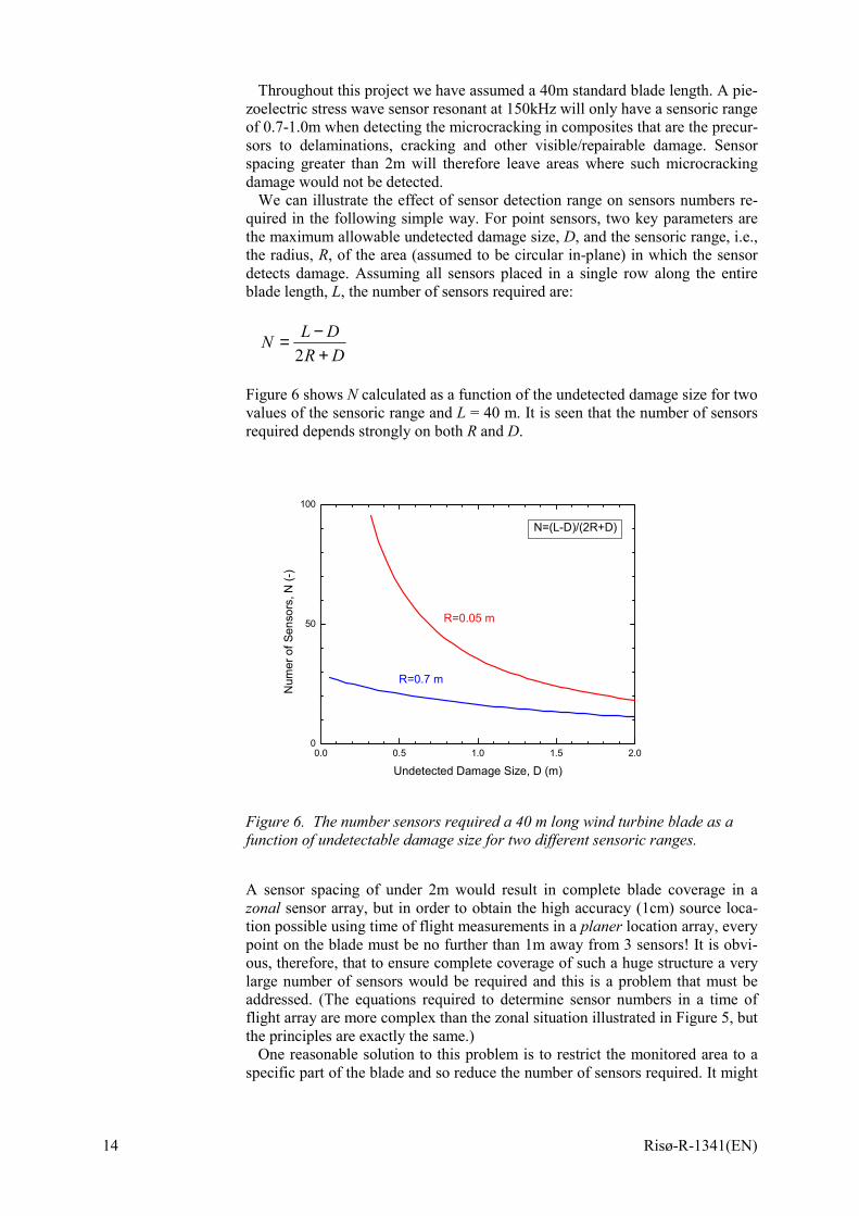
We can illustrate the effect of sensor detection range on sensors numbers re-quired in the following simple way. For point sensors, two key parameters are the maximum allowable undetected damage size, D, and the sensoric range, i.e., the radius, R, of the area (assumed to be circular in-plane) in which the sensor detects damage. Assuming all sensors placed in a single row along the entire blade length, L, the number of sensors required are:
DRDLN
+−=
2
Figure 6 shows N calculated as a function of the undetected damage size for two values of the sensoric range and L = 40 m. It is seen that the number of sensors required depends strongly on both R and D.
0.0 0.5 1.0 1.5 2.00
50
100
N=(L-D)/(2R+D)
R=0.7 m
R=0.05 m
Num
er o
f Sen
sors
, N (-
)
Undetected Damage Size, D (m)
Figure 6. The number sensors required a 40 m long wind turbine blade as a function of undetectable damage size for two different sensoric ranges.
A sensor spacing of under 2m would result in complete blade coverage in a zonal sensor array, but in order to obtain the high accuracy (1cm) source loca-tion possible using time of flight measurements in a planer location array, every point on the blade must be no further than 1m away from 3 sensors! It is obvi-ous, therefore, that to ensure complete coverage of such a huge structure a very large number of sensors would be required and this is a problem that must be addressed. (The equations required to determine sensor numbers in a time of flight array are more complex than the zonal situation illustrated in Figure 5, but the principles are exactly the same.)
One reasonable solution to this problem is to restrict the monitored area to a specific part of the blade and so reduce the number of sensors required. It might
Risø-R-1341(EN) 15
be decided, for example, to only have sensors along the trailing edge, or along the central spar, or around the blade root, or at the mid-blade area, and so on.
Another solution that may prove to be satisfactory is to restrict the number of sensors to a set number. These sensors are then “zoned” along the length of the blade. A profile of the stress wave activity along the blade can be produced that may be very useful in speeding up scheduled blade inspections, but it is ac-cepted that some areas of the blade are not being covered by the monitoring sys-tem.
Further solutions are more advanced and it may not be feasible to attempt them in a large structure until the practice of health monitoring with these sen-sors is more thoroughly developed. These include the use of alternative sensor types such as smart piezoelectric layers, multi-resonant sensor heads and mobile sensors; as well as advanced analysis functions such as signal relevant risetime and duration calculations, partial energy frequency analysis and pre-signal in-terpretations. These future solutions are briefly mentioned in the remaining sec-tions of this document.
1.14 Sensor adaptation Smart layers
Developments in polymer type piezoelectric layers may make it possible to cover a structure surface with an inbuilt non-destructive sensing technique using passive and active acousto-ultrasonics to detect the evolution of damage and the presence of defects.
Multi-resonant sensor heads
Sensors resonant at different frequencies respond to different components of the broad bandwidth signals emitted by damaged polymer composites. At low fre-quencies (60kHz) sensors have a greater range, but are more influenced by noise sources. At higher frequencies (300kHz) the sensor detection range is poor, but noise rejection is perfect. 150kHz is a compromise between these ex-tremes. A sensor that could change its resonant frequency could also adapt its function, using low frequency resonance to give the greatest sensoric range, mid frequency resonance to track down local source location and high frequency resonance to interpret damage type without noise interference.
Mobile sensors
This ability would be of greatest benefit where the sensor itself was mobile over the structure surface. Such a system would probably require a system of rails or tracks to be incorporated into the internal shell stiffening of the blade, needless to say this is likely to entail some major design work! Rolling, dry contact sen-sors exist for composite materials (Figure 4) and would need to have the ability to move along their track with the position controlled by the Can-bus microcon-troller. In theory, a truly free roaming sensor would be capable of monitoring an entire blade surface on its own and accurately determining location and diag-nosing damage sources (this assumes that load cycle N is roughly comparable to load cycle N+1 and N-1, where N is any in-situ load cycle). However even where a sensor is only mobile along a 5m long rail the effective sensoric range of the sensors is massively increased and, as we have discussed (Figure 6), this is the main obstacle to full structure monitoring with a reasonable number of sensors.
16 Risø-R-1341(EN)
1.15 Advanced analysis Signal relative threshold calculation In order to calculate waveform characteristics such as risetime and duration it is necessary to establish a threshold voltage. Most systems use a threshold value chosen and entered by the operator. However, this results in values for risetime and duration which are more influenced more by the operator input than by the signal waveform they are intended to represent. If a system calculated the threshold independently for each signal waveform received (for example desig-nating threshold as equal to a quarter of the signals peak amplitude) it would give a more meaningful value for risetime and duration. An accurate and signal dependant risetime characteristic could be of great benefit in calculating dis-tance from source information from a single hit. This is because the stress wave energy travels at different speeds, and so the signal becomes more dispersed the further it has travelled. When plotting risetime of a stress wave against source distance using standard AE equipment it is common to see a general increase in signal risetime with distance from source. However the slope is not linear and increases in a step wise manner. By altering the method of determining risetime a linear relationship with source distance is anticipated.
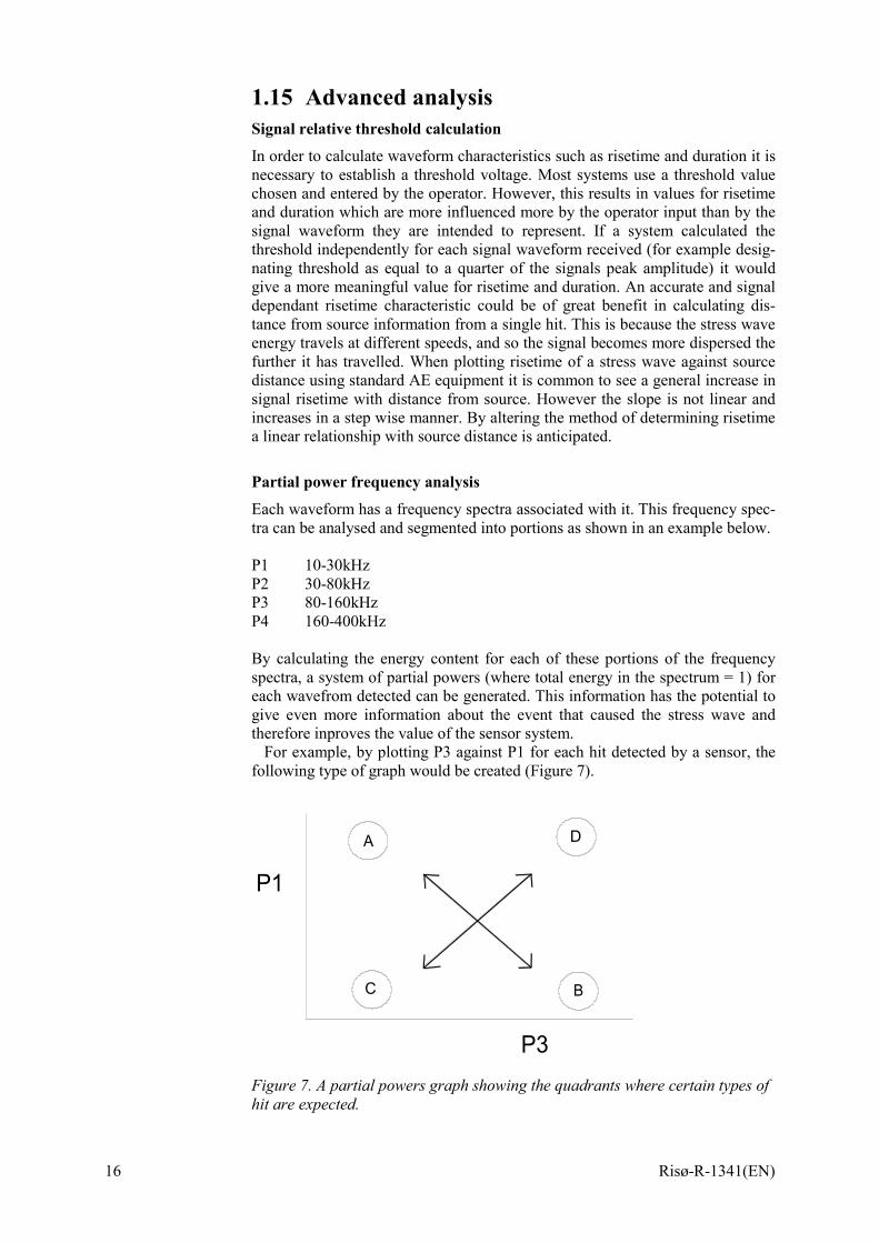
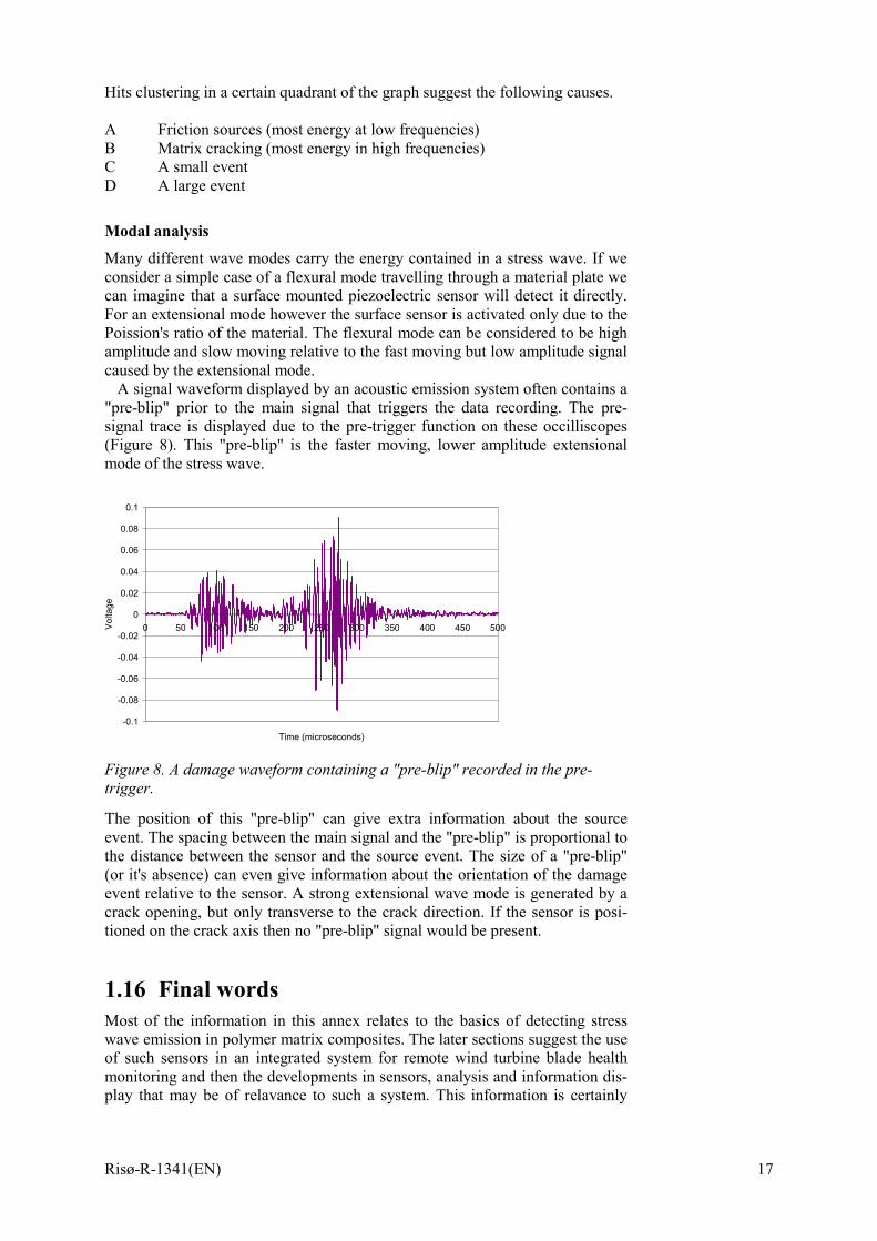
Partial power frequency analysis Each waveform has a frequency spectra associated with it. This frequency spec-tra can be analysed and segmented into portions as shown in an example below. P1 10-30kHz P2 30-80kHz P3 80-160kHz P4 160-400kHz By calculating the energy content for each of these portions of the frequency spectra, a system of partial powers (where total energy in the spectrum = 1) for each wavefrom detected can be generated. This information has the potential to give even more information about the event that caused the stress wave and therefore inproves the value of the sensor system.
For example, by plotting P3 against P1 for each hit detected by a sensor, the following type of graph would be created (Figure 7).
P1
P3
A
BC
D
Figure 7. A partial powers graph showing the quadrants where certain types of hit are expected.
Risø-R-1341(EN) 17
Hits clustering in a certain quadrant of the graph suggest the following causes. A Friction sources (most energy at low frequencies) B Matrix cracking (most energy in high frequencies) C A small event D A large event
Modal analysis Many different wave modes carry the energy contained in a stress wave. If we consider a simple case of a flexural mode travelling through a material plate we can imagine that a surface mounted piezoelectric sensor will detect it directly. For an extensional mode however the surface sensor is activated only due to the Poission's ratio of the material. The flexural mode can be considered to be high amplitude and slow moving relative to the fast moving but low amplitude signal caused by the extensional mode.
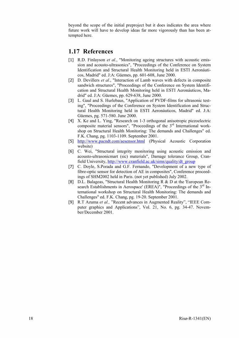
A signal waveform displayed by an acoustic emission system often contains a "pre-blip" prior to the main signal that triggers the data recording. The pre-signal trace is displayed due to the pre-trigger function on these occilliscopes (Figure 8). This "pre-blip" is the faster moving, lower amplitude extensional mode of the stress wave.
-0.1
-0.08
-0.06
-0.04
-0.02
0
0.02
0.04
0.06
0.08
0.1
0 50 100 150 200 250 300 350 400 450 500
Time (microseconds)
Volta
ge
Figure 8. A damage waveform containing a "pre-blip" recorded in the pre-trigger.
The position of this "pre-blip" can give extra information about the source event. The spacing between the main signal and the "pre-blip" is proportional to the distance between the sensor and the source event. The size of a "pre-blip" (or it's absence) can even give information about the orientation of the damage event relative to the sensor. A strong extensional wave mode is generated by a crack opening, but only transverse to the crack direction. If the sensor is posi-tioned on the crack axis then no "pre-blip" signal would be present.
1.16 Final words Most of the information in this annex relates to the basics of detecting stress wave emission in polymer matrix composites. The later sections suggest the use of such sensors in an integrated system for remote wind turbine blade health monitoring and then the developments in sensors, analysis and information dis-play that may be of relavance to such a system. This information is certainly
18 Risø-R-1341(EN)
beyond the scope of the initial preproject but it does indicates the area where future work will have to develop ideas far more vigorously than has been at-tempted here.
1.17 References [1] R.D. Finlayson et al., "Monitoring ageing structures with acoustic emis-
sion and acousto-ultrasonics", "Proceedings of the Conference on System Identification and Structural Health Monitoring held in ESTI Aeronáuti-cos, Madrid" ed. J:A: Güemes, pp. 601-608, June 2000.
[2] D. Devillers et al., "Interaction of Lamb waves with defects in composite sandwich structures", "Proceedings of the Conference on System Identifi-cation and Structural Health Monitoring held in ESTI Aeronáuticos, Ma-drid" ed. J:A: Güemes, pp. 629-638, June 2000.
[3] L. Gaul and S. Hurlebaus, "Application of PVDF-films for ultrasonic test-ing", "Proceedings of the Conference on System Identification and Struc-tural Health Monitoring held in ESTI Aeronáuticos, Madrid" ed. J:A: Güemes, pg. 571-580. June 2000.
[4] X. Ke and L. Ying, "Research on 1-3 orthogonal anisotropic piezoelectric composite material sensors", "Proceedings of the 3rd International work-shop on Structural Health Monitoring: The demands and Challenges" ed. F.K. Chang, pg. 1103-1109. September 2001.
[5] http://www.pacndt.com/aesensor.html (Physical Acoustic Corporation website)
[6] C. Wei, "Structural integrity monitoring using acoustic emission and acousto-ultrasonicmart (sic) materials", Damage tolerance Group, Cran-field University, http://www.cranfield.ac.uk/sims/quality/dt_group
[7] C. Doyle, S.Porada and G.F. Fernando, "Development of a new type of fibre-optic sensor for detection of AE in composites", Conference proceed-ings of SHM2002 held in Paris. (not yet published) July 2002.
[8] D.L. Balageas, "Structural Health Monitoring R & D at the 'European Re-search Establishments in Aerospace' (EREA)", "Proceedings of the 3rd In-ternational workshop on Structural Health Monitoring: The demands and Challenges" ed. F.K. Chang, pg. 19-20. September 2001.
[9] R.T Azuma et al., ”Recent advances in Augmented Reality”, “IEEE Com-puter graphics and Applications”, Vol. 21, No. 6, pg. 34-47. Novem-ber/December 2001.
Risø-R-1341(EN) 19
2 Fiber optic sensors for strain and displacement measurements Peter Sendrup, DELTA Danish Electronics, Light & Optics Lars Lading, Sensor Technology Center The use of optical fiber based sensors for measurement of strain and damage is a relatively well-established technique. We shall here give a short introduction to the basic principles, present a survey of methods and published material on the subject. A dedicated sensor developed for the project is described in Annex C.
2.1 Basic principles A typical optical fiber is illustrated in Figure 9. The fiber consists of a core and a cladding possibly with a protective coating. The refractive index of the core is slightly higher than the refractive index of the cladding. If light is focused at the end of the fiber it is so that light within a solid angle confined by
( ) 2/121 nna −=θ (1)
will propagate within the fiber. The refractive indices of the core and the clad-ding are given by n1 and n2, respectively. Light impinging at an angle larger than θa will escape the fiber. It is customary to characterize fibers according to the number of modes they can support. A mode is here defined as a solution to Maxwell's equations. Fibers for demanding applications are generally made of glass. However, polymer fibers can be made at a lower cost and may have ad-vantages for short-range applications.
A single mode propagating in free space will in general exhibit a beam diver-gence in the far field given by the following expression
a/λα ≈ , (2)
where λ is the wavelength of the light and a is the radius of the light beam at its smallest diameter. Laser light is often confined to a single spatial mode whereas light from a thermal source will occupy a large number of modes. The number of modes that a fibre can support is given by
( )2/. αθaConstM = . (3)
The constant depends on the polarization possibilities for the light and the spe-cific type of refractive index variations in the fiber. Single mode fibers are pref-erably used for high-speed long haul transmission. Multimode fibers are gener-ally more robust in terms of coupling light in and out. However, in several other respects they are inferior to single mode fibers.

20 Risø-R-1341(EN)
Figure 9. An optical fiber.
Now, if a fiber is bent some of the light propagating in the fiber may escape. This is the principle for one of the simplest types of fiber optic sensors and in fact also the principle that has been applied in the present project.
Figure 10. A fiber optic strain-gauge based on an undulated structure. The fiber is placed between two blocks with matching undulated structures. If the of the blocks is displaced relative to the other the radius of curvature of the fiber is changed, which changes the light transmission of the fiber. This is measured and converted to a displacement.
The fiber may itself be prepared in such a way that its transmission properties are affected by displacements of the medium in which it is imbedded. The sim-plest type is a cut in the fibre so that a cavity (a so-called Fabry-Perot cavity) is formed between the two tips. The cavity will have characteristic optical reso-nance frequencies at which the transmission is high. At other frequencies the reflection is high. The resonance frequencies are changed when the spacing be-tween the two tips is changed. This can provide for an extremely sensitive dis-placement detector for displacements in along the axis of the fibre. Acoustic emissions may be detected with such a sensor.
A sensor type derived from the cavity type is based on a distributed refractive index structure written in the fibre. Such fibres with imbedded gratings (called Bragg gratings) have been developed for in-line filtering of optical signals in optical communication systems. Since the optical pass-band is displaced if the fibre is subjected to strain this type of fibre grating can also be applied to strain measurements.
Other mechanical sensing methods may be based in changes in light scattering in the fibre itself as a consequence of mechanical stress or strain. Coherent scat-tering from density waves (which may be thermally excited) is called Brillouin scattering, whereas incoherent scattering or scattering from nonpropagating structures is called Rayleigh scattering.
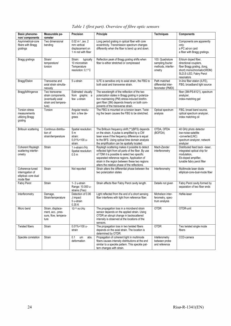
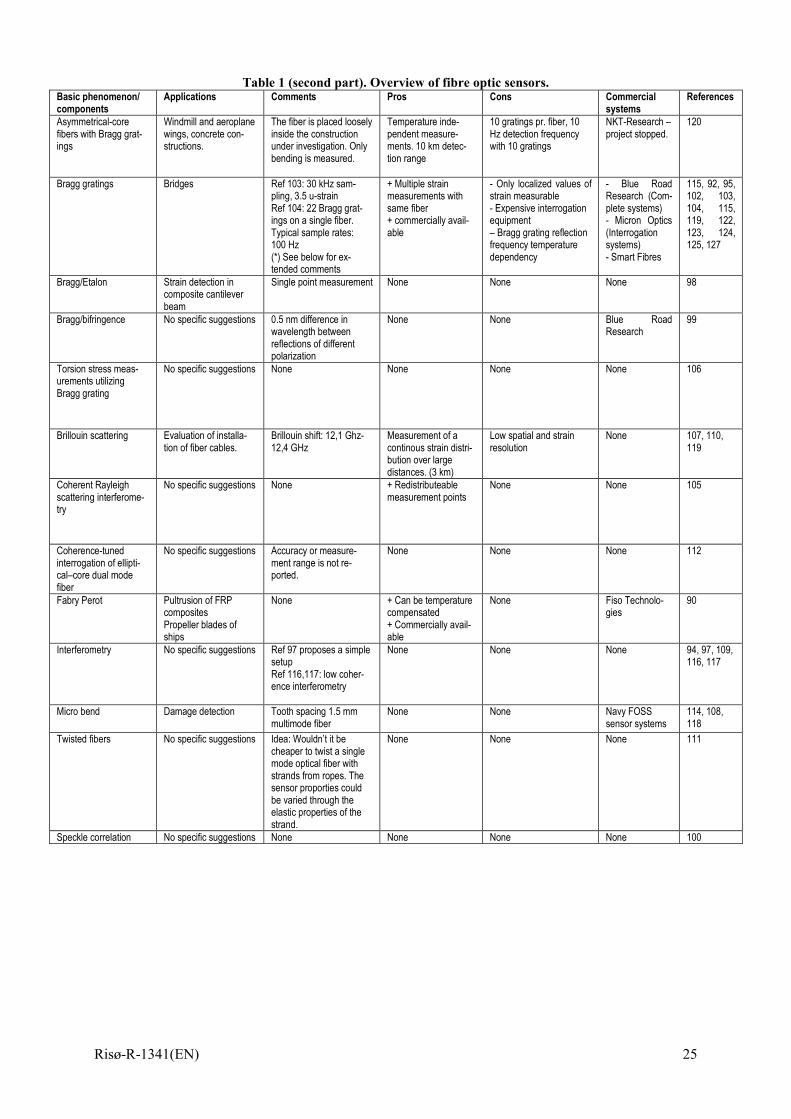
2.2 Survey of fiber optic sensing methods This survey is based on a number of selected papers given in the reference list. The aim has been to provide the best possible overview of the different sensor technologies. The result of the survey is presented in one large table at the end of this section. The table summarises and classifies the different sensor tech-nologies. The classification is neither unique nor completely systematic, but it is hopefully intuitively obvious and fulfils its intention: to provide a comprehen-sive overview of the different sensor technologies.
θθθθ

Risø-R-1341(EN) 21
The different categories of sensor types are given in the first column; ‘Basic phenomenon/components’. The sensor types are defined by the basic compo-nent(s) of the sensor (eg. Bragg gratings), or by the physical phenomenon lying behind the sensor principle (eg. Brillouin scattering). The number of categories becomes relatively large using this classification principle.
The content of second column, ‘Measured parameter’, is the physical pa-rameter measured by the sensor. In most cases this parameter is axial strain, or temperature.
The accuracy or resolution of the parameter measured by the sensor is given in the third column, ‘Accuracy’. The presented values are of course rough es-timates, and not based on uncertainty budgets.
Column 5 ‘Principle’ describes how the measured physical parameter is re-lated to the optical properties of the basic component or to the physical phe-nomenon on which the sensor principle is based.
The column ‘Techniques’ provides key words indicating the techniques used to interrogate the sensor. The different sensor types can typically be interrogated in a number of ways.
The column ‘Components’ describes some of the typical components used together with the basic component to form the sensor system.
The column ‘Applications’ contains both actual applications and proposed applications. Many of the papers present the results of pure generic research. For some sensor categories there has therefore been no proposals for applica-tions.
The column ‘Comments’ contains specific pieces of information that cannot be placed in any of the other columns.
The next two columns are ‘Pros’ and ‘Cons’. These columns are only scarcely filled out. They are only filled out if the current sensor type has proper-ties that separate it from the rest of the sensor types in either a particularly posi-tive or negative way.
The second last column ‘Commercial systems’ is even more scarcely filled out than ‘Pros’ and ‘Cons’, for the simple reason that only a few of the sensor types are commercially available in ‘ready to use’ systems.
The last column ‘References’, refers to the papers in the reference list de-scribing the specific sensor type.
2.3 Evaluation The commercial systems are based on following sensor types: • Bragg gratings (Blue road research, Micron Optics, Smart fibres) • Fabry Perot resonators (Fiso technologies) • Micro bend (Navy FOSS sensor systems) These sensor types are robust and there is a simple relation between the meas-ured optical parameter and the requested physical parameter (strain, tempera-ture). Micro bend sensors are cheap and the Bragg gratings are potentially cheap in large quantities. Blue Road Research has estimated a price of 20 $ for mass production in one of their application notes.
The sensor element in the ‘Torsion stress measurement utilizing Bragg gratings’ consists of a rod around which there is wrapped a fiber with a Bragg grating. This sensor is therefore in what could be called the ‘Bragg grating fam-ily’. The sensor type Bragg/etalon is based on a combination of fiber Bragg grating and a Fabry Perot etalon and it is obviously also in this family. This special combination enables a combined measurement of axial- and transverse strain.
22 Risø-R-1341(EN)
Other sensor categories are: • Brillouin scattering • Rayleigh scattering • Twisted fibers As they are presented, they are based on relatively sophisticated measurement schemes (OTDA) that are estimated to require expensive instrumentation, but at the same time offers a small spatial resolution. These techniques are primarily addressed to the fiber optic communication industry where it is desired to in-spect the conditions of several kilometre long fiber optic communication cables. Furthermore, the twisted fiber sensor can be regarded as a variant of the micro bend fiber sensor.
The ‘Inteferometry’ sensor category covers two different sensors. Both use the Michelson interferometric set-up, but in one case the light source is a coher-ent He-Ne laser and in the other case it is a low coherent light source. In both cases it is possible to measure a change in the optical path length of the sensor element which will change when the sensor element is stretched or compressed. These set-ups are not as well proven as those listed under commercial systems.
The ‘speckle correlation’ fiber strain sensor is neither a well proven tech-nique and the connection between strain and the measured optical parameter (the speckle pattern recorded with a CCD camera) is not physically simple. The measurement of strain using this sensor type must therefore rely on a calibra-tion.
The micro bend sensor and the fiber Bragg grating sensor are overall con-cluded to be the most simple, the most well proven and potentially cheapest fi-ber based strain sensors. It has therefore been decided that the potential of these sensor types for detection of strain and damage in composites is investigated experimentally in this project.
At the present time a specific set-up based on a Bragg grating is selected. This set-up is available at the company Blue Road Research and details about the sensor system is given below.
It is the intention to make a very simple version of the micro bend system. The idea is that the sensor simply has to consist of a piece of single mode opti-cal fiber with a U-bend. The U-bend is placed at a location in the composite structure where a crack is expected to appear, for instance in the adhesive layer between to parts. The U-bend is oriented so that the U is stretched when the crack appears, with the result that the transmittance increases.
Risø-R-1341(EN) 23
2.4 A Bragg grating sensor set-up
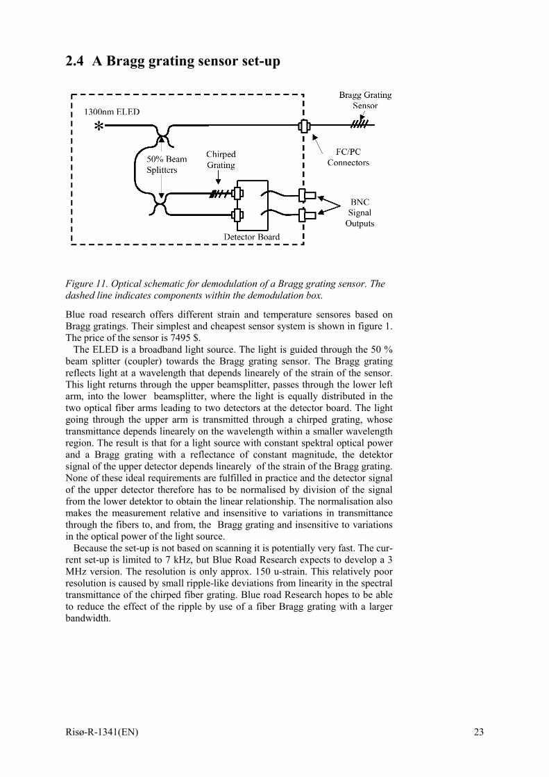
Figure 11. Optical schematic for demodulation of a Bragg grating sensor. The dashed line indicates components within the demodulation box.
Blue road research offers different strain and temperature sensores based on Bragg gratings. Their simplest and cheapest sensor system is shown in figure 1. The price of the sensor is 7495 $.
The ELED is a broadband light source. The light is guided through the 50 % beam splitter (coupler) towards the Bragg grating sensor. The Bragg grating reflects light at a wavelength that depends linearely of the strain of the sensor. This light returns through the upper beamsplitter, passes through the lower left arm, into the lower beamsplitter, where the light is equally distributed in the two optical fiber arms leading to two detectors at the detector board. The light going through the upper arm is transmitted through a chirped grating, whose transmittance depends linearely on the wavelength within a smaller wavelength region. The result is that for a light source with constant spektral optical power and a Bragg grating with a reflectance of constant magnitude, the detektor signal of the upper detector depends linearely of the strain of the Bragg grating. None of these ideal requirements are fulfilled in practice and the detector signal of the upper detector therefore has to be normalised by division of the signal from the lower detektor to obtain the linear relationship. The normalisation also makes the measurement relative and insensitive to variations in transmittance through the fibers to, and from, the Bragg grating and insensitive to variations in the optical power of the light source.
Because the set-up is not based on scanning it is potentially very fast. The cur-rent set-up is limited to 7 kHz, but Blue Road Research expects to develop a 3 MHz version. The resolution is only approx. 150 u-strain. This relatively poor resolution is caused by small ripple-like deviations from linearity in the spectral transmittance of the chirped fiber grating. Blue road Research hopes to be able to reduce the effect of the ripple by use of a fiber Bragg grating with a larger bandwidth.
24 Risø-R-1341(EN)
Table 1 (first part). Overview of fibre optic sensors
Basic phenome-non/ components
Measurable pa-rameter
Precision Principle Techniques Components
Asymmetrical-core fibers with Bragg gratings
Two dimensional bending
0.02 m-1, (ex. 2 mm vertical displacement on 1 m rod with fiber
Long period grating in optical fiber with core eccentricity. Transmission spectrum changes differently when the fiber is bend up and down.
Components are apparently only: a PC ad-on card a fiber with Bragg gratings.
Bragg gratings Strain/ temperature/ torsion
Strain: typically 10 microstrain Temperature resolution: 0,1°C
Reflection peak of Bragg grating shifts when fiber is either stretched or compressed
103: Quadrature sampling,fourier methods, interfer-ometry
Erbium doped fiber, directional couplers, fiber Bragg grating, (long, short) monochromator(WDM) SLD,E-LED, Fabry Perot resonators
Bragg/Etalon Transverse and axial strain simulta-neously
5 u-strain ILFE is sensitive only to axial strain, the FBG to both axial and transverse strain.
Path matched differential inter-ferometer (PMDI)
In-line fiber etalon (ILFE), FBG, broadband light source
Bragg/bifringence Two transverse strain components, (eventually axial strain and tempera-ture)
Estimated visually from graphs: a few u-strain
The wavelength of the reflection of the two polarization states in Bragg grating in polariza-tion maintaining (PM) stress-induced birefrin-gent fiber (3M) depends linearly on both com-ponents of the transverse strain.
fiber (3M-PS-6121), spectrum analyzer, index-matching gel
Torsion stress measurements utilizing Bragg grating
Torsion Angular resolu-tion: a few de-grees
The FBG is mounted on a torsion beam. Twist-ing the beam causes the FBG to be stretched.
Optical spectrum analysis
FBG, broad band source, optical spectrum analyzer, index matching oil
Brillouin scattering Continous distribu-tion of strain/temperature
Spatial resolution: 5 m strain: 0,01%=100 u-strain.
The Brillouin frequency shift (**)(BFS) depends on the strain. A pulse is amplified by a CW laser wave if the frequency difference is equal to the BFS. Using optical time domain analysis the amplification can be spatially located.
OTDA, OFDA (BOFDA)
40 GHz photo detector low-noise-satellite -converter(LNC) spectrum analyzer, network analyzer
Coherent Rayleigh scattering interfer-ometry
Strain 1 n-strain/√Hz Spatial resolution: 0.5 m
Rayleigh scattering makes it possible to detect reflected light from all parts of the fiber. By use of TDM it is possible to select two specific separated reference regions. Application of strain in the region between these two regions alters the relative phase of the reflections.
Mach-Zender interferometry
Distributed feed back –laser, integrated optical chip for modulation, Eb-doped amplifier, tunable fabry perot filter
Coherence-tuned interrogation of elliptical–core dual mode fiber
Strain Not reported Strain alters the differential phase between the two polarization states
Interferometry Multimode laser diode elliptical-core-dual-mode fiber
Fabry Perot Strain 1- 2 u-strain Range: 10.000 u-strains (Fiso)
Strain affects fiber Fabry Perot cavity length. Details not given Fabry Perot cavity formed by separation of two fiber ends
Interferometry Damage, Strain/temperature
Detection of 0.06 J impact 5 u-strain 0.35 K
Light reflected from the end of a short sensing fiber interferes with light from reference fiber.
Michelson inter-ferometry, spec-trum analysis
HeNe-laser
Micro bend Strain, displace-ment, acc., pres-sure, flow, tempera-ture
10-10 m/√Hz The propagation loss in a microbend strain sensor depends on the applied strain. Using OTDR an abrupt change in backscattered intensity is observed at the locations of the sensors.
OTDR OTDR-unit
Twisted fibers Strain 0.01%=100 u-strain
The propagation loss in two twisted fibers depends on the axial strain. The location is determined by OTDR.
OTDR Two twisted single mode fibers
Speckle correlation Strain 0.1 um abs. deformation
Propagation of coherent light in multimode fibers causes intensity distributions at the end similar to a speckle pattern. This speckle pat-tern changes with strain.
Inteferometry between probe and reference
CCD-camera
Risø-R-1341(EN) 25
Table 1 (second part). Overview of fibre optic sensors. Basic phenomenon/ components
Applications Comments Pros Cons Commercial systems
References
Asymmetrical-core fibers with Bragg grat-ings
Windmill and aeroplane wings, concrete con-structions.
The fiber is placed loosely inside the construction under investigation. Only bending is measured.
Temperature inde-pendent measure-ments. 10 km detec-tion range
10 gratings pr. fiber, 10 Hz detection frequency with 10 gratings
NKT-Research – project stopped.
120
Bragg gratings Bridges Ref 103: 30 kHz sam-pling, 3.5 u-strain Ref 104: 22 Bragg grat-ings on a single fiber. Typical sample rates: 100 Hz (*) See below for ex-tended comments
+ Multiple strain measurements with same fiber + commercially avail-able
- Only localized values of strain measurable - Expensive interrogation equipment – Bragg grating reflection frequency temperature dependency
- Blue Road Research (Com-plete systems) - Micron Optics (Interrogation systems) - Smart Fibres
115, 92, 95, 102, 103, 104, 115, 119, 122, 123, 124, 125, 127
Bragg/Etalon Strain detection in composite cantilever beam
Single point measurement None None None 98
Bragg/bifringence No specific suggestions 0.5 nm difference in wavelength between reflections of different polarization
None None Blue Road Research
99
Torsion stress meas-urements utilizing Bragg grating
No specific suggestions None None None None 106
Brillouin scattering Evaluation of installa-tion of fiber cables.
Brillouin shift: 12,1 Ghz-12,4 GHz
Measurement of a continous strain distri-bution over large distances. (3 km)
Low spatial and strain resolution
None 107, 110, 119
Coherent Rayleigh scattering interferome-try
No specific suggestions None + Redistributeable measurement points
None None 105
Coherence-tuned interrogation of ellipti-cal–core dual mode fiber
No specific suggestions Accuracy or measure-ment range is not re-ported.
None None None 112
Fabry Perot Pultrusion of FRP composites Propeller blades of ships
None + Can be temperature compensated + Commercially avail-able
None Fiso Technolo-gies
90
Interferometry No specific suggestions Ref 97 proposes a simple setup Ref 116,117: low coher-ence interferometry
None None None 94, 97, 109, 116, 117
Micro bend Damage detection Tooth spacing 1.5 mm multimode fiber
None None Navy FOSS sensor systems
114, 108, 118
Twisted fibers No specific suggestions Idea: Wouldn’t it be cheaper to twist a single mode optical fiber with strands from ropes. The sensor proporties could be varied through the elastic properties of the strand.
None None None 111
Speckle correlation No specific suggestions None None None None 100
26 Risø-R-1341(EN)
2.5 References 90 The use of Fabry Perot fiber optic sensors to monitor residual strains dur-
ing pultrusion of FRP composites, Kalamkarov, A.L., 1999, Composites Part B: Engineering, 30-2
92 Distributed fiber Bragg grating sensing in reinforced concrete structual components, Davis, M.A., 1997, Cement and Concrete Composites, 19-1
93 Technical notes - effectiveness and optimization of fiber Bragg grating sensor as embedded strain sensor, Tang, Liqun, 1999, Smart Materials and Structures, 8-1
94 Sensitivity coefficient evaluation of an embedded fiber-optic strain sen-sor, Libo Yuan, Limin Zhou, 1998, Sensors and Actuators A: Physical, 69-1
95 Fiber-optic Bragg grating sensors for bridge monitoring, Maaskant, R., 1997, Cement and concrete composites, 19-1
96 Sensors - an eight-channel fiber-optic Bragg grating and stimulated Bril-louin sensor system for simultaneous temperature and strain measure-ments, Posey Jr, R., 1999, IEEE Photonics Technology Letters, 11-12
97 Damage monitoring of carbon fiber-reinforced plastics with Michelson interferomietric fiber-optic sensors, Tsuda, H, 1999, Journal of Material Science, 34-17
98 Simultaneous measurement of two strain components in composite se-tructures using embedded fiber sensors, Jin, X. D., 1999, Journal of com-posite materials – Lancaster, 33-15
99 A fiber optic sensor for transverse strain measurements, Lawrence, C. M., 1999, Experimental Mechanics, 39-3
100 Optical fiber strain gauge based on speckle correlation, Pomarico, Juan A., 1999, Optics and Laser Technology, 31-3
101 Simultaneous sensing of the strain and points of failure in composite beams with embedded fiber optic Michelson sensor, Kwon, I.B., 1998, Composites Science and Technology, 57-12
102 State-of-strain evaluation with fiber Bragg grating rosettes: application to descrimination between strain and temeperature effects in fiber sensors, Magne, Sylvain Stephane Rougeault Manuel Vilela; Pierre Ferdinand, 1997, Applied Optics, 36-36
103 Fiber Bragg grating strain sensor demodlation with quadrature sampling of Mach-Sehnder interferometer, Song, Minho; Shizhuo Yin; Paul B. Ruffin, 2000, Applied Optics, 39-7
104 Distributed measurements of static strain in an optical fiber with multiple Bragg gratings at nominally equal wavelengths, Froggatt, Mark; Jason Moore, 1998, Applied Optics, 37-10
105 Strain sensing based on coherent Rayleigh scattering in an optical fiber, Posery Jr, R.; G.A. Johnson; S.T. Vohra, 2000, Electronics Letters, 36-20
Risø-R-1341(EN) 27
106 Linear fibre-grating-type sensing tuned by applying torsion stress, Zhang, Weigang; Xiaoyi Dong; Dejun Feng; Zixion Qin; Qida Zhao, 2000, Elec-tronics Letters, 33-20
107 First measurements of strain distribution along filed-installed optical fi-bers using Brillouin spectroscopy, Mitsuhiro Tateda, Tsuneo Horiguchi, Toshio Kurashima, Koushi Ishihara, 1990, Journal of Lightwave Tech-nology, vol. 8 no 9
108 Fiber-optic strain gauge, Jonathan D. Weiss, 1989, Journal of Lightwave Technology, vol. 7 no 9
109 Fiber-optical dual-technique sensor for simultaneous measurement of strain and temperature, Ashish M. Vengsarkar, W. Craig Michie, Ljilja Jankovic, Brian Culshaw, Richard O. Claus, 1994, Journal of Lightwave Technology, vol. 12 no 1
110 Brillouin optical-fiber frequency-domain analysis for distributed tempera-ture and strain measurements, Dieter Garus, Torsten Gogolla, Katerina Krebber, Frank Schliep, 1997, Journal of Lightwave Technology, Vol 15 no 4
111 A strain sensor using twisted optical fibers, Tetsuji Abe, Yutaka Mitsu-naga, Hiroaki Koga, 1989, Journal of Lightwave Technology, Vol 7 No 3
112 Coherence-tuned interrogation of a remote elliptical-core, dual-mode fi-ber strain sensor, K. Bohnert, G. C. de Wit, J. Nehring, 1995, Journal of Lightwave Technology, Vol. 13 no 1
113 Determination of the individual strain-optic coefficients in single-mode optical fibers, Axel Bertholds, Réne Dändliker, 1988, Journal of Light-wave Technology, vol. 6 no. 1
114 Historical review of microbend fiber-optic sensors, John W. Berthold III, 1995, Journal of Lightwave Technology, Vol. 13 no. 7
115 In-fiber Bragg-grating temperature sensor system for medical applica-tions, Yun-jiang Rao, David J. Webb, David A. Jackson, Lin Zhang, I. Bennion, 1997, Journal of Lightwave Technology, vol. 15 no 5
116 Industrial prototype of fiber-optic sensor network for the thermal moni-toring of the turbogenerator of a nuclear power plant-design, qualifica-tion, and settlement, C. Meunier, J.J. Guerin, M. Lequime, M. Rioual, E. Noel, D. Eguiazabal, D. Fleury, J. Maurin, R. Mon, 1995, Journal of Lightwave Technology, vol 13 no 7
117 Interferometric fiber-optic sensing based on the modulation of group de-lay and first order dispersion: Application to strain-temperature meas-urand, Dónal A. Flavin, Roy McBride, Julian D. C. Jones, 1995, Journal of Lightwave Technology, vol 13 no 7
118 A fiber optic microbend sensor for distrubuted sensing application in the structual strain monitoring, Fei Luo, Jingyan Liu, Naibing Ma, T.F. Morse, 1999, Sensors and Actuators, A - Physical 75
119 An eight-channel fiber-optic Bragg grating and stimulated Brillouin sen-sor system for simultaneous temperature and strain measurements, Ralph
28 Risø-R-1341(EN)
Posey Jr., Sandeep T. Vohra, 1999, IEEE Photonics Technology Letters, 11-12
120 Fibre optic bending sensor - no cross sensitivity, René Engel Kristiansen, 2000, NKT
121 Photonics, Fiber optic sensors and their application in smart structures, A. Selvarajan, A. Asundi, 2000,
www.ntu.edu.sg/mpe/programmes/sensors/sensors/fos/fosass/photonics
122 Instrumentation of a high-speed surface effect ship for structural response characterisation during seatrials, Karianne Pran, Gregg Johnson, Alf Egil Jensen, Knut Arne Hegstad, Geir Sagvolden, Øystein Farsund, Chia-Chen Chang, from authors
123 Smart masts chart novel design rules for polymers, John Bell, 1998, Opto and Lasers Europe, 55
124 Simultaneous measurement of strain and temperature by use of a single-fiber Bragg grating and an erbium-doped fiber amplifier, Jaehoon Jung, Hui Nam, Ju Han Lee, Namkyoo Park, Byoungho Lee, 1999, Applied Optics, 38-13
125 Simultaneous measurement of strain and temperature by use of a single fiber Bragg grating written in an erbium:ytterbium-doped fiber, Jaehoon Jung, Namkyoo Park, Byoungho Lee, 2000, Applied Optics , 39-7
126 Fiber-optic strain-displacement sensor employing nonlinear buckling, Karl F. Voss, Keith H. Wanser, 1997, Applied Optics, 36-13
127 Dynamic-strain measurement with dual-grating fiber sensor, Minho Song, Sang Bae Lee, Sang Sam Choi, Byoungho Lee, 1998, Applied optics, 37-16
128 Application of fiber-optic Bragg grating sensors in monitoring environ-mental loads of overhead power transmission lines, Leif Bjerkan, 2000, Applied Optics, 39-04
129 Application of Bragg grating sensors in characterization of scaled marine vehicele models, D. R. Hjelme, L. Bjerkan, S. Neegard, J.S. Rambech, J.V. Aarsnes, Applied Optics, 36-01
130 Distributed and multiplexed fibre grating sensors, Including discussion of problem areas, John P. Dakin, Mark Volanthen, 2000, IEICE Trans. Elec-tron., E83-03
131 Hybrid fiber Bragg grating/long period fiber grating sensor for strain/temperature discrimination, H. J. Patrick, G.M. Williams, A.D. Kersey, J.R. Pedrazzani, 1996, IEEE Photonics Technology Letters, 08-09
132 Optical Fiber long-period grating sensors, Vikram Bhatia, 1996, Optics Letters, 21-09
133 Effectiveness and optimization of fiber Breagg grating sensor as embed-ded strain sensor, Liqun Tnag, Xiaoming Tao, Chung-Loong Choy, 1999, Smart Material Structures, 08
Risø-R-1341(EN) 29
134 Characterisation of hybrid laminate fatigue crack growth, T. S. P. Austin, P. J. Gregson, University of Southampton
135 Fiber-optic strain gauge, Fiso Technologies
136 Embedded fibre optic lines, http://www.soton.ac.uk/ãustin/cfrp.html
137 Determination of process-induced residual stress in composite materials using embedded fiber optic sensors, Lawrence, C. M., Nelson, D.V., Bennett, T. E. , Spingarn, J. R., 1997, SPI Proceedings on Smart Struc-tures and Materials, 3042
138 White-light interferometric multimode fiber-optic strain sensor, Claude Belleville, Gaétan Duplain, 1993, Optics Letters, 18-01
139 In-situ monitoring og graphite/epoxy cure using optical fiber and ultra-sonic sensors, J.Y.Chen, S.V.Hoa, C.-K.Jen, H.Wang, 1997, 12th annual technical conference american society for composites
140 Smart skins - a step toward a practical fibre-optic sensor, Claude Belle-ville, André Morin, Serge Caron, Merv Edgecombe, Fiso (www.fiso.com)
141 Fiber optic strain gauge installation guide, Fiso
142 New generation of fiber-optic sensors for dam monitoring, P. Choquet, F. Juneau, F. Dadoun, 1999, Proceedings of the '99 International Conference on Dam Safty and Monitoring
143 Field monitoring of the ice load of an icebreaker propeller blade using fibre optic strain gauges, André Morin, Serge Caron, Richard Van Neste Merv H. Edgecombe, 1996, Smart structures and materials 1996: smart sensing, processing and instrumentation
30 Risø-R-1341(EN)
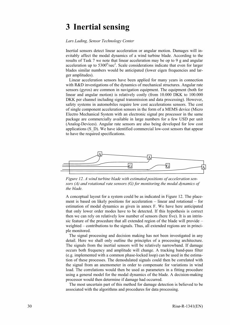
3 Inertial sensing Lars Lading, Sensor Technology Center Inertial sensors detect linear acceleration or angular motion. Damages will in-evitably affect the modal dynamics of a wind turbine blade. According to the results of Task 7 we note that linear acceleration may be op to 9 g and angular acceleration up to 53000/sec2. Scale considerations indicate that even for larger blades similar numbers would be anticipated (lower eigen frequencies and lar-ger amplitudes).
Linear acceleration sensors have been applied for many years in connection with R&D investigations of the dynamics of mechanical structures. Angular rate sensors (gyros) are common in navigation equipment. The equipment (both for linear and angular motion) is relatively costly (from 10.000 DKK to 100.000 DKK per channel including signal transmission and data processing). However, safety systems in automobiles require low cost accelerations sensors. The cost of single component acceleration sensors in the form of a MEMS device (Micro Electro Mechanical System with an electronic signal pre processor in the same package are commercially available in large numbers for a few USD per unit (Analog-Devices). Angular rate sensors are also being developed for low cost applications (S_D). We have identified commercial low-cost sensors that appear to have the required specifications.
Figure 12. A wind turbine blade with estimated positions of acceleration sen-sors (A) and rotational rate sensors (G) for monitoring the modal dynamics of the blade.
A conceptual layout for a system could be as indicated in Figure 12. The place-ment is based on likely positions for acceleration – linear and rotational – for estimation of modal dynamics as given in annex F. We have here anticipated that only lower order modes have to be detected. If this hypothesis is correct then we can rely on relatively low number of sensors (here five). It is an intrin-sic feature of the procedure that all extended region of the blade will provide – weighted – contributions to the signals. Thus, all extended regions are in princi-ple monitored.
The signal processing and decision making has not been investigated in any detail. Here we shall only outline the principles of a processing architecture. The signals from the inertial sensors will be relatively narrowband. If damage occurs both frequency and amplitude will change. A tracking band-pass filter (e.g. implemented with a common phase-locked loop) can be used in the estima-tion of these processes. The demodulated signals could then be correlated with the signal from an anemometer in order to compensate for variations in wind load. The correlations would then be used as parameters in a fitting procedure using a general model for the modal dynamics of the blade. A decision-making processor would then determine if damage had occurred.
The most uncertain part of this method for damage detection is believed to be associated with the algorithms and procedures for data processing.
A G G
AA

Risø-R-1341(EN) 31
References
Analog Devices Inc. produce a number of low-cost accelerometers (http://www.analog.com/technology/mems/accelerometers/designTools/selectionGuides/products.html). We do not have a formal quotation on prices. How-ever, from personal communications we have indications of prices around 1 USD for large volumes. Systron Donner Inertial Div. manufactures true inertial gyros (that is gyros where the operation does not depend on a gravitational force) (http://www.systron.com/). Also from personal communications we have indi-cations of a unit price of around 10 USD for volume delivery.
32 Risø-R-1341(EN)
4 Real-time X-ray Inspection Jørgen Rheinländer, InnospeXion Aps
Real-time radioscopy is a key technology for revelation of e.g.:
- missing glue between laminates;
- cracks and voids in the laminates;
- non-intended orientation of fibres;
- irregular lay-up (kink-band revelation).
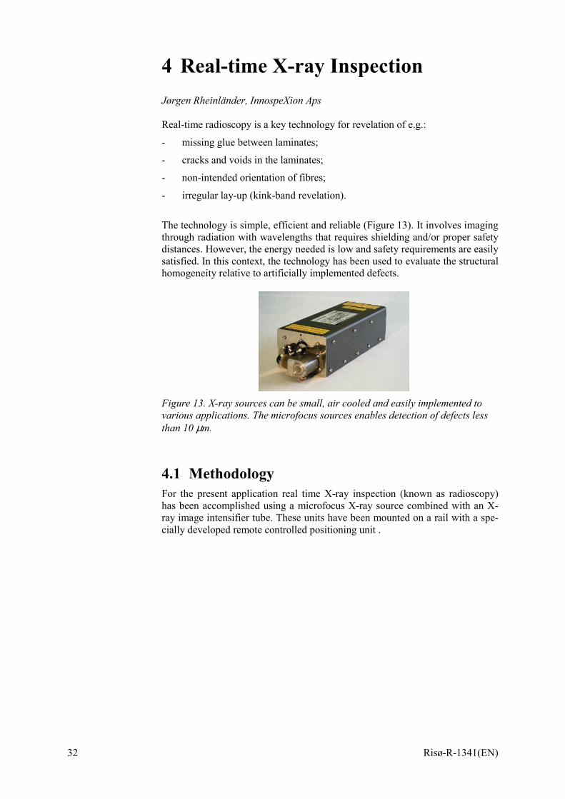
The technology is simple, efficient and reliable (Figure 13). It involves imaging through radiation with wavelengths that requires shielding and/or proper safety distances. However, the energy needed is low and safety requirements are easily satisfied. In this context, the technology has been used to evaluate the structural homogeneity relative to artificially implemented defects.
Figure 13. X-ray sources can be small, air cooled and easily implemented to various applications. The microfocus sources enables detection of defects less than 10 µm.
4.1 Methodology For the present application real time X-ray inspection (known as radioscopy) has been accomplished using a microfocus X-ray source combined with an X-ray image intensifier tube. These units have been mounted on a rail with a spe-cially developed remote controlled positioning unit .
Risø-R-1341(EN) 33
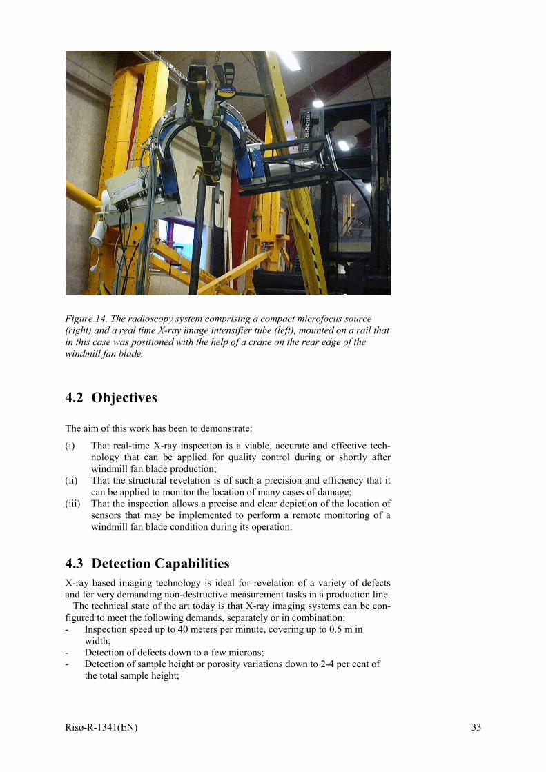
Figure 14. The radioscopy system comprising a compact microfocus source (right) and a real time X-ray image intensifier tube (left), mounted on a rail that in this case was positioned with the help of a crane on the rear edge of the windmill fan blade.
4.2 Objectives The aim of this work has been to demonstrate:
(i) That real-time X-ray inspection is a viable, accurate and effective tech-nology that can be applied for quality control during or shortly after windmill fan blade production;
(ii) That the structural revelation is of such a precision and efficiency that it can be applied to monitor the location of many cases of damage;
(iii) That the inspection allows a precise and clear depiction of the location of sensors that may be implemented to perform a remote monitoring of a windmill fan blade condition during its operation.
4.3 Detection Capabilities X-ray based imaging technology is ideal for revelation of a variety of defects and for very demanding non-destructive measurement tasks in a production line.
The technical state of the art today is that X-ray imaging systems can be con-figured to meet the following demands, separately or in combination: - Inspection speed up to 40 meters per minute, covering up to 0.5 m in
width; - Detection of defects down to a few microns; - Detection of sample height or porosity variations down to 2-4 per cent of
the total sample height;

34 Risø-R-1341(EN)
- Novel very compact detectors and small X-ray sources enable inspection of difficult to access parts and structures.
In this project, the important imaging capabilities are:
- Ability to detect defects down to 0.1 mm in lateral (2-Dimensions) exten-sion;
- Fast scanning capability (in this prototype case, about 1 meter per minute); - Low X-ray energy requirement leading to very modest shielding require-
ments; - Fast and easy set-up; - Quick and easy adjustments if scanning at other angles proves necessary. The concept used was a microfocus X-ray source combined with a 6 inch X-ray image intensifier. This was mounted on a rigid rail, as a prototype unit. The unit was moved by means of specially adapted motor drivers. Due to time con-straints on the development of the motor drivers, the holding torque was not properly adjustable and hence the up-downward scanning was relatively unsta-ble.
Figure 15. Mounting of remote controlled Non-destructive testing equipment around area of the failure, defect type 1. The X-ray source and the detecting camera is set on an inverted U-frame that again is mounted on a track for re-mote control. This set-up was originally developed for pipeline inspection but can as demonstrated easily be adapted for other purposes of inspection on other structures of similar dimensions.
4.4 Work Accomplished Using the set-up described and shown previously, the inspection method has been applied to monitor the progression of artificially implemented damages to a test windmill fan blade. The tests were conducted in the Risø windmill fan blade test facility at Sparkær, in Jutland, Denmark. All tests were conducted within the framework of the Public Service Obligation (PSO) project “Remote Monitoring of Windmills”, partly sponsored by ELKRAFT AS.
The assessment was performed on a 22m long windmill fan blade, supplied by LM Glasfiber AS.
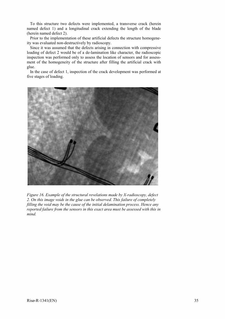
Risø-R-1341(EN) 35
To this structure two defects were implemented, a transverse crack (herein named defect 1) and a longitudinal crack extending the length of the blade (herein named defect 2).
Prior to the implementation of these artificial defects the structure homogene-ity was evaluated non-destructively by radioscopy.
Since it was assumed that the defects arising in connection with compressive loading of defect 2 would be of a de-lamination like character, the radioscopic inspection was performed only to assess the location of sensors and for assess-ment of the homogeneity of the structure after filling the artificial crack with glue.
In the case of defect 1, inspection of the crack development was performed at five stages of loading.
Figure 16. Example of the structural revelations made by X-radioscopy, defect 2. On this image voids in the glue can be observed. This failure of completely filling the void may be the cause of the initial delamination process. Hence any reported failure from the sensors in this exact area must be assessed with this in mind.
36 Risø-R-1341(EN)
5 Ultrasound inspection Jens Rusborg, FORCE Dynamics Ultrasound is the most widely used technique for inspection of composite mate-rials. The basic principle of the technique is that an ultrasonic wave is passed through the material. The ultrasonic wave can be reflected and/or mode con-verted by a defect. A transmitter transfers ultrasound waves into the material. A receiver will pick up the signal of the wave once it has passed through the mate-rial. In the simplest arrangement, the transmitter and receiver are placed on op-posite surfaces of the material. The technique may also be applied with a single transmitter/receiver transducer in pulse-echo mode or with separate transmit and receive transducers placed on the same side of the material. Finally ultrasound can be applied for detection of defects by means of acousto-ultrasonics, a com-parative technique, which can be applied either from one side or from both sides of the structure.
The transducers have to be moved across the surface in a controlled way to scan an area for defects.
Due to the large impedance mismatch between air and solid materials the transducers have to be coupled to the surface of the structure by liquids, gels or suitable matched materials. Coupling can be made by immersion in water, use of water jets or by a thin layer of gel.
In all cases the transmit time and/or amplitude of the ultrasound is monitored. The transit time can be used to determine the position of the defect relative to the position of the transducers. The amplitude can be used to assess the severity of the defect. The position of the defect along the surface and through the thick-ness can be determined. The data can be displayed in many ways. The most ap-plied data presentations are: A-Scan: Signal amplitude vs. transit time (the fundamental recording of the test) B-Scan: A cross sectional view (line scan) of the material. C-Scan: A plan view (surface scan) of the material. For field-testing the equipment on the marked range from small manual equip-ment to fully automated scanning equipment. Compared to metals the attenua-tion within composites is not always constant for a given thickness. In these cases application of automated C-scan inspection improve the evaluation of the scanning results. Automated inspection improves also the possibilities for evaluation of the size and depth of the defects. Small manual equipment can be applied in some cases but are most useful for determination of laminate thick-ness and detection of delaminations in laminates with small variations in thick-ness and attenuation.
5.1 Detection of delaminations and cracks in adhe-sions
Ultrasound is today the most applied method in finding delaminations in single skin laminates. Delaminations are orientated at right angles to an ultrasonic wave propagation at normal incident into a laminate, and therefore ideally aligned for detection by ultrasonics, since they reflect the ultrasound effectively. Cracks in adhesives oriented at right angles to an ultrasonic wave propagation at normal incident are also ideally alligned for detection of ultrasound. The test
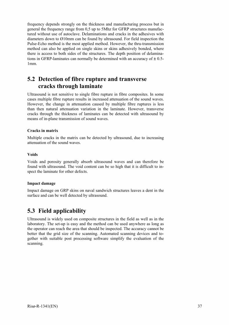
Risø-R-1341(EN) 37
frequency depends strongly on the thickness and manufacturing process but in general the frequency range from 0,5 up to 5Mhz for GFRP structures manufac-tured without use of autoclave. Delaminations and cracks in the adhesives with diameters down to Ø10mm can be found by ultrasound. For field inspection the Pulse-Echo method is the most applied method. However, the thru-transmission method can also be applied on single skins or skins adhesively bonded, where there is access to both sides of the structures. The depth position of delamina-tions in GFRP-laminates can normally be determined with an accuracy of ± 0.5-1mm.
5.2 Detection of fibre rupture and transverse cracks through laminate
Ultrasound is not sensitive to single fibre rupture in fibre composites. In some cases multiple fibre rupture results in increased attenuation of the sound waves. However, the change in attenuation caused by multiple fibre ruptures is less than then natural attenuation variation in the laminate. However, transverse cracks through the thickness of laminates can be detected with ultrasound by means of in-plane transmission of sound waves.
Cracks in matrix
Multiple cracks in the matrix can be detected by ultrasound, due to increasing attenuation of the sound waves.
Voids
Voids and porosity generally absorb ultrasound waves and can therefore be found with ultrasound. The void content can be so high that it is difficult to in-spect the laminate for other defects.
Impact damage Impact damage on GRP skins on naval sandwich structures leaves a dent in the surface and can be well detected by ultrasound.
5.3 Field applicability Ultrasound is widely used on composite structures in the field as well as in the laboratory. The set-up is easy and the method can be used anywhere as long as the operator can reach the area that should be inspected. The accuracy cannot be better that the grid size of the scanning. Automated scanning devices and to-gether with suitable post processing software simplify the evaluation of the scanning.
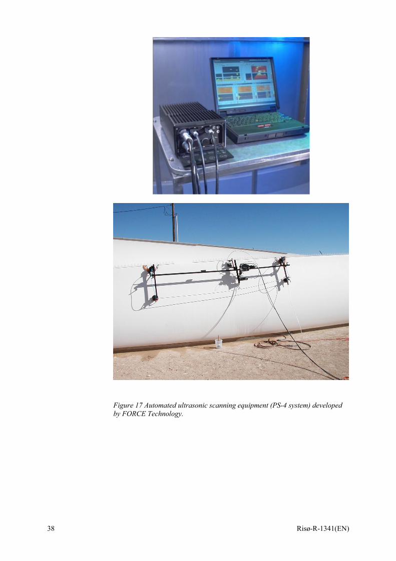
38 Risø-R-1341(EN)
Figure 17 Automated ultrasonic scanning equipment (PS-4 system) developed by FORCE Technology.
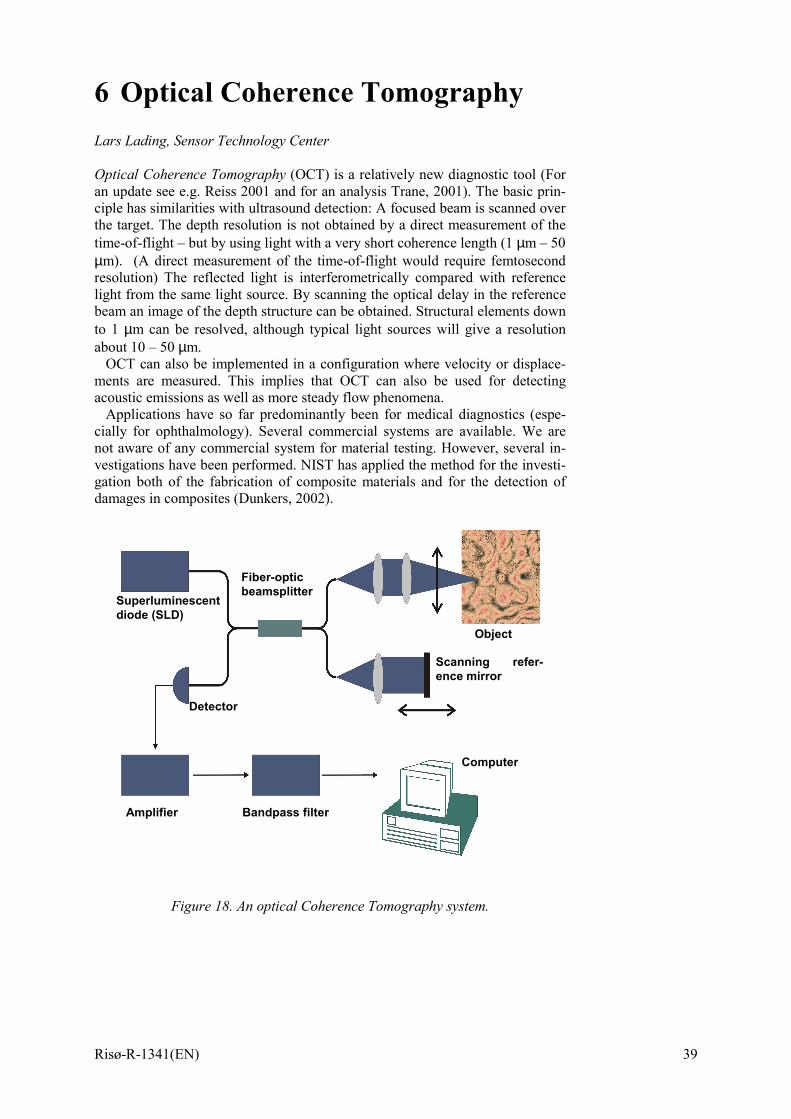
Risø-R-1341(EN) 39
6 Optical Coherence Tomography Lars Lading, Sensor Technology Center Optical Coherence Tomography (OCT) is a relatively new diagnostic tool (For an update see e.g. Reiss 2001 and for an analysis Trane, 2001). The basic prin-ciple has similarities with ultrasound detection: A focused beam is scanned over the target. The depth resolution is not obtained by a direct measurement of the time-of-flight – but by using light with a very short coherence length (1 µm – 50 µm). (A direct measurement of the time-of-flight would require femtosecond resolution) The reflected light is interferometrically compared with reference light from the same light source. By scanning the optical delay in the reference beam an image of the depth structure can be obtained. Structural elements down to 1 µm can be resolved, although typical light sources will give a resolution about 10 – 50 µm.
OCT can also be implemented in a configuration where velocity or displace-ments are measured. This implies that OCT can also be used for detecting acoustic emissions as well as more steady flow phenomena.
Applications have so far predominantly been for medical diagnostics (espe-cially for ophthalmology). Several commercial systems are available. We are not aware of any commercial system for material testing. However, several in-vestigations have been performed. NIST has applied the method for the investi-gation both of the fabrication of composite materials and for the detection of damages in composites (Dunkers, 2002).
Figure 18. An optical Coherence Tomography system.
Superluminescent diode (SLD)
Detector
Fiber-optic beamsplitter
Object
Scanning refer-ence mirror
Computer
Amplifier Bandpass filter

40 Risø-R-1341(EN)
References
Reiss, S. M., 2001, “OCT Update”, Biophotonics International, Dec. 2001, 40-45. Thrane, L., 2001, “Optical Coherence Tomography: Modeling and Applica-tions”, Ph.D. thesis, Technical University of Denmark, Risø National Labora-tory 76 p., ISBN 87-550-2882-9. Dunkers, J, “Optical Coherence Tomography Facility”, http://polymers.nist.gov/facilities/optical/index.html.
Risø-R-1341(EN) 41
7 Comparing Sensors for Damage Detection in Wind Turbine Blades Lars Lading, Sensor Technology Center Acoustic emission sensors (AE) with piezoelectric transducers and fiber optic displacement sensors were experimentally investigated in this project. Several other sensing schemes have been considered. We have made an initial compari-son of the different schemes and summarized the results in Table 1.
A complete sensing scheme based on acoustic emission could be based on 20 transducers. Commercial off-the-shelf prices for the components of the system described in section 1. is in the range of 300 to 400 thousand DKK. We antici-pate that in larger volumes a reduction of at least 50% in cost is possible. The electronics is relatively expensive. This is caused by the fact that AE transduc-ers generate a high bandwidth signal where initial signal processing is required. The preprocessing should preferably be done close to the transducers. However, placing signal processors in the turbine wings requires special prcations and is relatively expensive.
Acoustic emissions may also be detected with fiber optics: If the tip of the fi-ber is terminated with a tiny cavity (Fabry Perot) then the reflected signal will be perturbed by acoustic signals. Fiber systems are not readily available. How-ever, they would make it possible to avoid both signal processors and electrical cabling in the wings.
Inertial sensors will detect acceleration (linear and or rotation). Inertial sen-sors may utilize MEMS (micro electro-mechanical systems) devises as trans-ducers. However, inertial sensors may also be based on optics. This applies both to linear acceleration and rotation. MEMS devices with on-chip preprocessing have been developed for use in automobile safety systems. Thus, these devices are available at a very low price. The fiber optic counter parts are also being manufactured, but at much higher price than the MEMS devices. We have been informed that some companies are currently developing low cost versions to be used for car navigation equipment.
A dedicated fiber optic transducer was developed for this project (Annex C). Assuming that cracks in the trailing edge must be detected if they exceed 1 m we assumed that 40 transducers would be necessary. The cost of the fibers themselves could be made negligible. The rest of the transducer has been as-sumed to be made by mechanical processing of metal pieces. Injection molding based on polymers would provide for a much lower production cost, but a higher tooling cost.
Semiconductor strain gauges may also be applied. However, we did not find that they could form the basis for a viable sensor system. A combination of in-adequate robustness, electrical wiring has (initially) disqualified them.
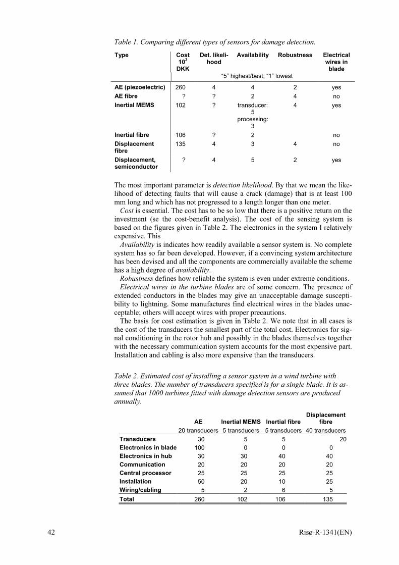
42 Risø-R-1341(EN)
Table 1. Comparing different types of sensors for damage detection.
Type Cost103
DKK
Det. likeli-hood
Availability Robustness Electrical wires in
blade “5” highest/best; “1” lowest
AE (piezoelectric) 260 4 4 2 yes AE fibre ? ? 2 4 no Inertial MEMS 102 ? transducer:
5 processing:
3
4 yes
Inertial fibre 106 ? 2 no Displacement fibre
135 4 3 4 no
Displacement, semiconductor
? 4 5 2 yes
The most important parameter is detection likelihood. By that we mean the like-lihood of detecting faults that will cause a crack (damage) that is at least 100 mm long and which has not progressed to a length longer than one meter.
Cost is essential. The cost has to be so low that there is a positive return on the investment (se the cost-benefit analysis). The cost of the sensing system is based on the figures given in Table 2. The electronics in the system I relatively expensive. This
Availability is indicates how readily available a sensor system is. No complete system has so far been developed. However, if a convincing system architecture has been devised and all the components are commercially available the scheme has a high degree of availability.
Robustness defines how reliable the system is even under extreme conditions. Electrical wires in the turbine blades are of some concern. The presence of
extended conductors in the blades may give an unacceptable damage suscepti-bility to lightning. Some manufactures find electrical wires in the blades unac-ceptable; others will accept wires with proper precautions.
The basis for cost estimation is given in Table 2. We note that in all cases is the cost of the transducers the smallest part of the total cost. Electronics for sig-nal conditioning in the rotor hub and possibly in the blades themselves together with the necessary communication system accounts for the most expensive part. Installation and cabling is also more expensive than the transducers.
Table 2. Estimated cost of installing a sensor system in a wind turbine with three blades. The number of transducers specified is for a single blade. It is as-sumed that 1000 turbines fitted with damage detection sensors are produced annually.
AE Inertial MEMS Inertial fibre Displacement
fibre 20 transducers 5 transducers 5 transducers 40 transducers Transducers 30 5 5 20Electronics in blade 100 0 0 0 Electronics in hub 30 30 40 40 Communication 20 20 20 20 Central processor 25 25 25 25 Installation 50 20 10 25 Wiring/cabling 5 2 6 5 Total 260 102 106 135

Risø-R-1341(EN) 43

Mission To promote an innovative and environmentally sustainable technological development within the areas of energy, industrial technology and bioproduction through research, innovation and advisory services.
Vision Risø’s research shall extend the boundaries for the understanding of nature’s processes and interactions right down to the molecular nanoscale. The results obtained shall set new trends for the development of sustainable technologies within the fields of energy, industrial technology and biotechnology. The efforts made shall benefit Danish society and lead to the development of new multi-billion industries. ISBN 87-550-3056-4 ISBN 87-550-3057-2 (Internet) ISSN 0106-2840 Risø National Laboratory Information Service Department P.O. Box 49 DK-4000 Roskilde Denmark Telephone +45 4677 4004 [email protected] Fax +45 4677 4013 Website www.risoe.dk
Bibliographic Data Sheet Risø-R-1341(EN) Title and authors Fundamentals for Remote Structural Health Monitoring of Wind Turbine Blades – a Preproject Annex B - Sensors and Non-Destructive Testing Methods for Damage Detec-tion in Wind Turbine Blades Lars Lading, Malcolm McGugan, Peder Sendrup, Jørgen Rheinländer, Jens Rusborg ISBN ISSN ISBN 87-550-3056-4 ISBN 87-550-3057-2 (Internet) 0106-2840 Department or group Date Materials Research Department May 2002 Groups own reg. number(s) Project/contract No(s) PSO Funding Through ELKRAFT System Bro-91.055 FU nr. 1102 Sponsorship Pages Tables Illustrations References 43 2 18 143 Abstract (max. 2000 characters) This annex provides a description of the sensor schemes and the non-destructive testing (NDT) methods that have been investigated in this project. Acoustic emission and fibre optic sensors are described in some detail whereas only the key features of well-established NDT methods are presented. Estimates of the cost of different sensor systems are given and the advantages and disadvantages of the different schemes is discussed. Descriptors INIS/EDB ACOUSTIC EMISSION TESTING; COMPARATIVE EVALUATIONS; COST ESTIMATION; DAMAGE; FIBER OPTICS; NONDESTRUCTIVE TESTING; REMOTE SENSING; STRAIN GAGES; TURBINE BLADES; WIND TURBINES