Fundamentals Digital Design Overview - Amazon S3 · Digital Design Overview ... nMidterms (2) 20%...
13
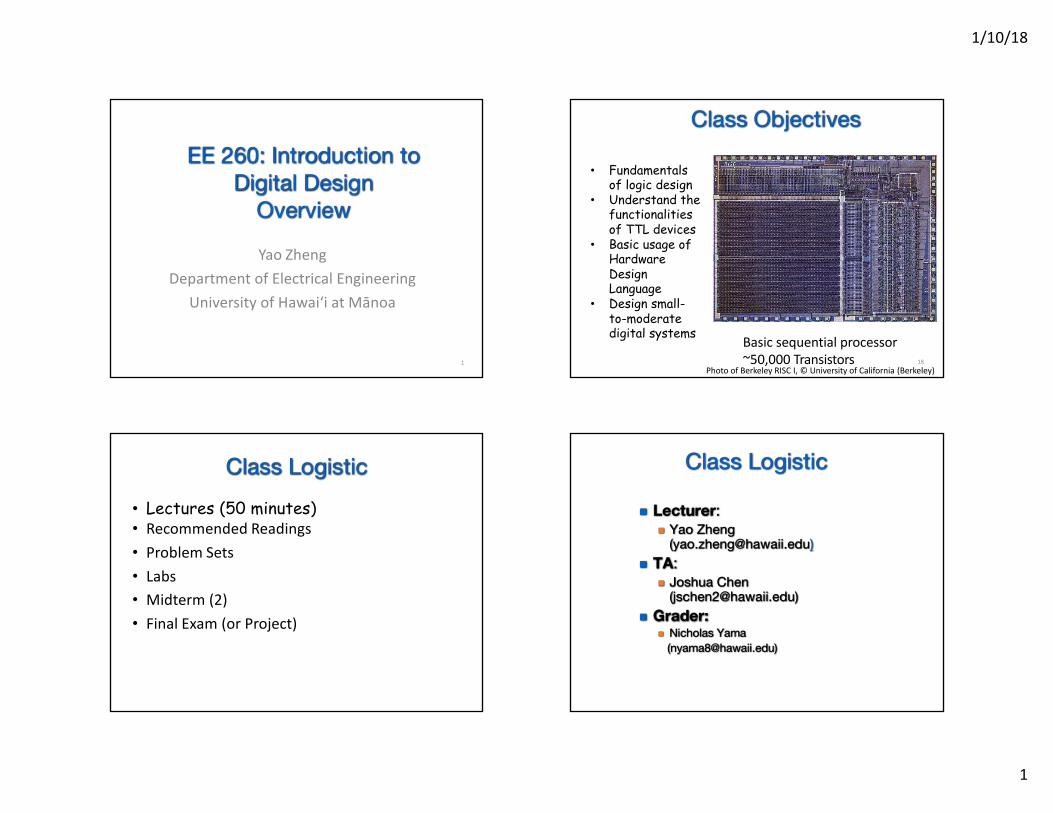
1/10/18 1 EE 2 60 : Introduction to Digital Design Overview Yao Zheng Department of Electrical Engineering University of Hawaiʻi at Mānoa 1 Class Objectives Basic sequential processor ~50,000 Transistors 18 Photo of Berkeley RISC I, © University of California (Berkeley) • Fundamentals of logic design • Understand the functionalities of TTL devices • Basic usage of Hardware Design Language • Design small- to-moderate digital systems Class Logistic • Lectures (50 minutes) • Recommended Readings • Problem Sets • Labs • Midterm (2) • Final Exam (or Project) Class Logistic n Lecturer : n Yao Zheng ([email protected] ) n TA : n Joshua Chen ([email protected]) n Grader: n Nicholas Yama ( [email protected])
Transcript of Fundamentals Digital Design Overview - Amazon S3 · Digital Design Overview ... nMidterms (2) 20%...
1/10/18
1
EE 260: Introduction toDigital Design
Overview
Yao ZhengDepartmentofElectrical Engineering
UniversityofHawaiʻiat Mānoa
1
Class Objectives
Basicsequentialprocessor~50,000 Transistors 18
PhotoofBerkeleyRISCI,©UniversityofCalifornia (Berkeley)
• Fundamentals of logic design
• Understand the functionalities of TTL devices
• Basic usage of Hardware Design Language
• Design small-to-moderate digital systems
Class Logistic• Lectures (50 minutes)• Recommended Readings• Problem Sets• Labs• Midterm (2)• Final Exam(orProject)
Class Logistic
n Lecturer:n Yao Zheng
([email protected])n TA:
n Joshua Chen ([email protected])
n Grader:n Nicholas Yama

1/10/18
2
Class Logisticn Lecture:
Mondays, Wednesdays, and Fridays 9:30am-10:20am, Marine Science Building 100.
n Laboratory:Tuesdays 9:00am-11:45am, Holmes Hall 451.
n Office hours:Mondays and Wednesdays 14:00pm-
16:00pm or email for appointment, Holmes Hall 437.
Class Logisticn Course website:
n http://www2.hawaii.edu/~yaozheng/course/ee260_spring_2018/
n Piazza:n https://piazza.com/hawaii/spring2018/ee260
n Github Classroomn https://ee260-2018-spring-
signup.herokuapp.com
Course Logisticn Textbook:
Required: Digital Design Principles and Practice with Verilog (5th Edition):
n Interactive Digital Access Program (through Laulima)
n Bookstore
n Optional: FPGA Prototyping By Verilog Examples: Xilinx Spartan-3 Version
n Amazon
Course Logisticn Grading:
Homework 25%n Discussion 10%n Midterms (2) 20%n Final Exam 20%n Lab Work 25%

1/10/18
3
Course Logisticn Basic Topics:
n Boolean algebran Combinational logicn Sequential building blocksn Finite state machine
n Advanced Topics:n Arithmetic structuresn Pipelinen Cache and Memory
n Hardware Description Languagen Verilog
Know What you are Getting into
~700,000,000Transistors
The materials in this class
The state-of-the-art
Application
11
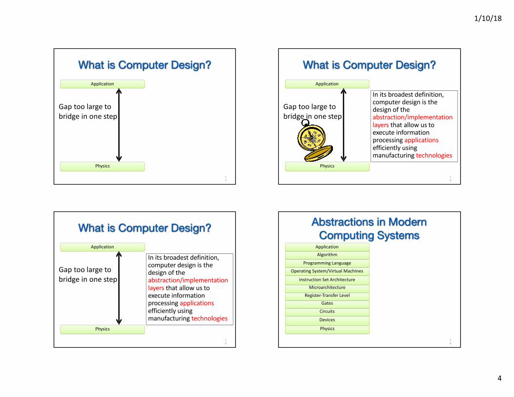
What is Computer Design? What is Computer Design?
Physics
Application
12
1/10/18
4
What is Computer Design?
Physics
Application
Gaptoolargetobridgeinone step
13
What is Computer Design?
Initsbroadestdefinition,computerdesign isthedesignoftheabstraction/implementationlayers that allow us toexecuteinformationprocessingapplicationsefficientlyusingmanufacturing technologies
Physics
Application
Gaptoolargetobridgeinone step
14
What is Computer Design?
Initsbroadestdefinition,computerdesign isthedesignoftheabstraction/implementationlayers that allow us toexecuteinformationprocessingapplicationsefficientlyusingmanufacturing technologies
Physics
Application
Gaptoolargetobridgeinone step
15
Abstractions in ModernComputing Systems
ApplicationAlgorithm
Programming Language
OperatingSystem/Virtual Machines
InstructionSet ArchitectureMicroarchitecture
Register-Transfer LevelGates
Circuits
Devices
Physics
16

1/10/18
5
Abstractions in ModernComputing Systems
ApplicationAlgorithm
Programming Language
OperatingSystem/Virtual Machines
InstructionSet ArchitectureMicroarchitecture
Register-Transfer LevelGates
Circuits
Devices
Physics
17
What is an Application
18
• The first digital systems were mechanical and used base-10 representation.
• Most popular applications: arithmetic and scientific computation
The Babbage Difference Engine (1834)25,000 parts cost: £17,470
Why Digital
19
• 1854: George Boole shows that logic is math, not just philosophy!
• Boolean algebra: the mathematics of binary values
000
01
10
0
0
11 1
0 1
1 0
AND OR NOT
000
01
10
1
1
11 1
Digital Electronics
Key Link Between Logic and Circuits
• Despite existence of relays and introduction of vacuum tube in 1906 digital electronics did not emerge for thirty years!
• Claude Shannon notices similarities between Boolean and electronic telephone switches
• Shannon’s 1937 MIT Master’s Thesis introduces the world to binary digital electronics
01 0
10 1
+
Lee de Forest, 1906
The Vacuum
Tube
Claude ShannonCourtesy of Jonah Sacks. Used with permission.

1/10/18
6
Evolution of Digital Electronics
UNIVAC, 1951
1900 adds/sec
Vacuum Tubes
ENIAC, 1946
IBM System/360, 1964
500,000 adds/sec
Transistors
First Transistor Bell Labs, 1948
VLSI Circuits
Intel Itanium, 2003
2,000,000,000adds/sec
4004, 1971
[from Kurzweil]
13
Major Technolog
y Generation
sBipolar
CMOS
nMOS
pMOS
Relays
VacuumTubes
Electromechanical
Sequential ProcessorPerformance
23FromHennessyandPattersonEd.5ImageCopyright©2011,ElsevierInc.Allrights Reserved.
RISC
24FromHennessyandPattersonEd.5ImageCopyright©2011,ElsevierInc.Allrights Reserved.
Sequential ProcessorPerformance

1/10/18
7
Sequential ProcessorPerformance
RISC
Move to multi-processor
25FromHennessyandPattersonEd.5ImageCopyright©2011,ElsevierInc.Allrights Reserved.
Hardware Implementation
Boolean Logic and State
Building Digital Systems• Goal: Building binary digital solutions to computational
problems
Behavioral Description
conversion to binary, Booelan algebra
device selectionand wiring
algorithm selection, flowcharts, etc.
Problem Statement• Labs & Design project• Product specs
• Algorithms, RTL, etc.• Flowcharts• State transition diagram
• Logic equations• Circuit schematics
• TTL Gates (AND,OR,XOR…)• Modules (counter, shifter)• Programmable Logic
Hardware Implementation
HDL Description
Building Digital Systems
Behavioral Descriptionsoftware-like programming
automated synthesis
algorithm selection, flowcharts, etc.
Problem Statement• Labs & Design project
Product specs
• Algorithms, RTL, etc.• Flowcharts• State transition diagram
• Verilog code• VHDL code
• Programmable logic• Custom ASICs
• Logic synthesis using a Hardware Description Language (HDL)automates the most tedious and error-prone aspects of design
A/D
Sync.
digitize
Digital System Model
• Digital processing systems consist of a datapath, memory, and control Early machines for arithmetic had insufficient memory, and often depended on users for control
• Today’s digital systems are increasingly embedded into everyday places and things
• Richer interaction with the user and environment
Data Processing
Controlsynchronize
MemoryAnalog Inputs
(sensors, audio, video, tablet)
Digital Inputs(peripherals,
buses, switches)
D/A
Digital Outputs
(peripherals, buses, lights)
Analog Outputs
(actuators, motors, multimedia)

1/10/18
8
Digital System Model
29
Memory: stores programs, i/o dataDatapath: perform arithmetic and other data-processing operationsControl Unit: supervises the flow of informationI/O: places program into memoryCPU: executes program from memory instruction by instruction. Control unit manipulates datapath to execute instructions.
Processor: contains CPU, FPU and MMUFPU (Floating Point Unit) : perform f-p operationsMMU (Memory Management Unit): layers of memory that helps instruction fetching and data I/O. Internal/external cache (very fast), RAM (between disk and cache)
Example Digital Systemsn Digital Computer
n Usually design to maximize performance. "Optimized for speed"
- Usually designed to minimize cost. “Optimized for low cost”
- Of course, low cost comes at the expense of speed.
• Handheld Calculator
Example Digital Systemsn Digital Watch
n Low power operation comes at the expense of:n lower speedn higher cost Designed to minimize power.
Single battery must last for years.
Basic Design Tradeoffs
n You can improve on one at the expense of worsening one or both of the others.
n These tradeoffs exist at every level in the system design - every sub-piece and component.
n Design Specification -n Functional Description. n Performance, cost, power constraints.
n As a designer you must make the tradeoffs necessary to achieve the function within the constraints.

1/10/18
9
Cost vs Speed vs Energy
• X86Instruction Set• QuadCore• 125W• Decode3 Instructions/Cycle/Core• 64KBL1ICache,64KBL1D Cache• 512KBL2 Cache• Out-of-order• 2.6GHz
AMD PhenomX4 Intel Atom• X86Instruction Set• Single Core• 2W• Decode2 Instructions/Cycle/Core• 32KBL1ICache,24KBL1D Cache• 512KBL2 Cache• In-order• 1.6GHz
ImageCredit: Intel
ImageCredit: AMD35
Cost vs Speed vs Energy
• X86Instruction Set• QuadCore• 125W• Decode3 Instructions/Cycle/Core• 64KBL1ICache,64KBL1D Cache• 512KBL2 Cache• Out-of-order• 2.6GHz
AMD PhenomX4 IBM POWER7• PowerInstruction Set• Eight Core• 200W• Decode6 Instructions/Cycle/Core• 32KBL1ICache,32KBL1D Cache• 256KBL2 Cache• Out-of-order• 4.25GHz
ImageCredit: AMD
ImageCredit: IBMCourtesyofInternationalBusinessMachinesCorporation,©InternationalBusinessMachines Corporation.
36
Design Representation Hierarchy in Designsn Helps control complexity -
n by hiding details and reducing the total number of things to handle at any time.
n Modulalizes the design -n divide and conquer n simplifies implementation and debugging
n Top-Down Design n Starts at the top (root) and works down by
successive refinement. n Bottom-up Design
n Starts at the leaves & puts pieces together to build up the design.
n Which is better?n In practice both are needed & used.
n Need top-down divide and conquer to handle the complexity.
n Need bottom-up because in a well designed system, the structure is influence by what primitves are available.

1/10/18
10
Software Aspects of Design
n In computer-aided design (CAD) various tools are available today to improve productivity, correctness and the quality of designs.
n Ways of digital design in CAD:n Schematic entry: schematic diagrams to
be drawn on screen.n HDLs : Hardware description languagesn Simulators: debug and check
37
Hardware structures can be modeled effectively in either VHDL and Verilog. Verilog is similar to c and a bit easier to learn.
Verilog and VHDL
38
• Created by GatewayDesign Automation in 1985;now an IEEE standard
• Initially an interpreted language for gate-level simulation
• Less explicit typing (e.g., compiler will pad arguments of different widths)
• No special extensions for large designs
• Commissioned in 1981 by Department of Defense; now an IEEE standard
• Initially created for ASICsynthesis
• Strongly typed;potentiallyverbose code
• Strong support for package management and large designs
VHDL Verilog
Verilog• Behavioral or Algorithmic Level
D Highest level in the Verilog HDLD Design specified in terms of algorithm (functionality) without hardware
details. Similar to “c” type specificationD Most common level of description
• Dataflow LevelD The flow of data through components is specified based on the idea of how
data is processed• Gate Level
D Specified as wiring between logic gatesD Not practical for large examples
• Switch LevelD Description in terms of switching (modeling a transistor)D No useful in general logic design – we won’t use it
A design mix and match all levels in one design is possible.In general Register Transfer Level (RTL) is used for a combination of Behavioral and Dataflow descriptions
Verilog• Misconceptions
D The coding style or clarity does not matter as long as it worksD Two different Verilog encodings that simulate the same way will
synthesize to the same set of gatesD Synthesis just can’t be as good as a design done by humans
• Shades of assembly language versus a higher level language
• What can be SynthesizedD Combinational Functions
• Multiplexors, Encoders, Decoders, Comparators, Parity Generator Adders, Subtractors, ALUs, Multipliers
• Random logicD Control Logic
• FSMs
• What can’t be SynthesizedD Precise timing blocks (e.g., delay a signal by 2ns)D Large memory blocks (can be done, but very inefficient)
Understand what constructs are used in simulation vs. hardware mapping
1/10/18
11
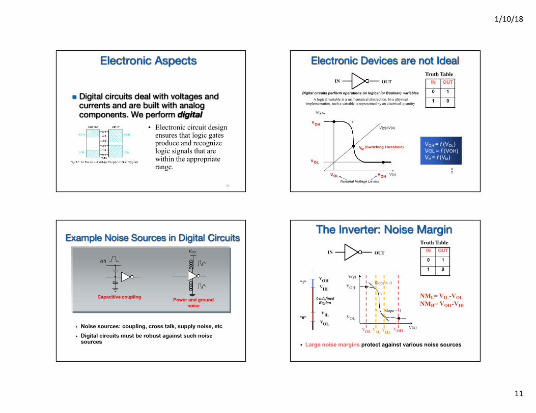
Electronic Aspects
n Digital circuits deal with voltages and currents and are built with analog components. We perform digital abstraction only.
41
• Electronic circuit design ensures that logic gates produce and recognize logic signals that are within the appropriate range.
Electronic Devices are not Ideal
42
VOH = f (VOL) VOL = f (VOH) VM = f (VM)
IN OUT IN OUT
0 1
1 0
Truth Table
V(x)
Digital circuits perform operations on logical (or Boolean) variables
A logical variable is a mathematical abstraction. In a physical implementation, such a variable is represented by an electrical quantity
V(y)
VOH
VOL
VM
VOL
fV(y)=V(x)
(Switching Threshold)
VOHNominal Voltage Levels
Example Noise Sources in Digital Circuits
Capacitive coupling
v(t)
Power and ground noise
VDD
• Noise sources: coupling, cross talk, supply noise, etc• Digital circuits must be robust against such noise
sources
The Inverter: Noise Margin
IN OUT IN OUT
0 1
1 0
V(x)
V(y)
VOH
VOL
VIL IH
Slope = -1
Slope = -1
VOL V VOH
"1"
"0"
VOHVIH
VILVOL
Undefined Region
• Large noise margins protect against various noise sources
NML= VIL -VOL NMH= VOH-VIH
Truth Table

1/10/18
12
Regenerative PropertyA chain of inverters
v0 v1 v2 v3 v4 v5 v6
V(V
olt) v0
v1v2
1
3
5
2 1 0 2 4 6 8 10
Simulated response
v2
v1
f (v)
finv(v)
outv3
v0 int (nsec)
| Voltage gain | should be > 1 between logic states
Verification and Testing• Design can be fun. Verification/testing is hard work.• Verification by simulation (and formally through test
benches) is a critical part of the design process.• The physical hardware must be tested to debug
tested mapping process and manufacturingdefects.
• Physical realizations often do not allow access to internalsignals. Need special tool to observe and control internalstate.
Verification and Design for Test (DFT) are important components of digital design
B3 B2 B1 B0 Val0 0 0 0 00 0 0 1 10 0 1 0 20 0 1 1 30 1 0 0 40 1 0 1 50 1 1 0 60 1 1 1 71 0 0 0 81 0 0 1 9
L1
L6
L2
L3
L7
L4
L5
Case Study of a Simple Logic Design:Seven Segment Display
n Chip to drive digital display
B3 B2 B1 B0 Val L1 L2 L3 L4 L5 L6 L7
0 0 0 0 0 1 0 1 1 1 1 1
0 0 0 1 1 0 0 0 0 0 1 1
0 0 1 0 2 1 1 1 0 1 1 0
0 0 1 1 3 1 1 1 0 0 1 1
0 1 0 0 4 0 1 0 1 0 1 1
0 1 0 1 5 1 1 1 1 0 0 1
0 1 1 0 6 1 1 1 1 1 0 1
0 1 1 1 7 1 0 0 0 0 1 1
1 0 0 0 8 1 1 1 1 1 1 1
1 0 0 1 9 1 1 1 1 0 1 1
L1
L6
L2
L3
L7
L4
L5
Case Study (cont.)

1/10/18
13
Case Study (cont.)
n Implement L4:B3 B2 B1 B0 L4
0 0 0 0 1
0 0 0 1 0
0 0 1 0 0
0 0 1 1 0
0 1 0 0 1
0 1 0 1 1
0 1 1 0 1
0 1 1 1 0
1 0 0 0 1
1 0 0 1 1 Some gate level implementationof the Boolean function for L4
Case Study (cont.)
n Verilog Code: