FUNDAMENTAL SAFETY OVERVIEW UK-EPR …epr-reactor.co.uk/ssmod/liblocal/docs/V3/Volume 2...CHAPTER: A...
35
CHAPTER: A PAGE : 1 / 35 UK-EPR FUNDAMENTAL SAFETY OVERVIEW VOLUME 2: DESIGN AND SAFETY REPORT CHAPTER A: INTRODUCTION AND GLOSSARY - Copyright © 2007 AREVA NP & EDF All Rights Reserved This document is the property of AREVA NP and EDF. It contains proprietary information and, except for affiliate companies of AREVA NP and/or EDF, may not be reproduced or copied in whole or in part nor may it be furnished to others without the prior written permission of AREVA NP and EDF. In any case, any re-exportation of the document shall be subject to the prior written permission of AREVA NP and EDF. It may not be used in any way that is or may be injurious to AREVA NP or EDF. This document and any copies that may have been made must be returned on request. The design, engineering and other information contained in this document have been prepared by or on behalf of AREVA NP and EDF in connection with their request for generic design assessment of the EPR TM design by the UK nuclear regulatory authorities. No use of or right to copy any of this information, other than by the UK nuclear regulatory authorities and their contractors in support of generic design assessment of AREVA NP’s and EDF’s joint submittal, is authorized. Trade Mark EPR TM is an AREVA Trade Mark. For information address: AREVA NP SAS An AREVA and Siemens Company Tour AREVA 92084 Paris La Défense Cedex France EDF Division Ingéniérie Nucléaire Centre National d'Equipement Nucléaire 165-173, avenue Pierre Brossolette BP900 92542 Montrouge France
-
Upload
truongkhanh -
Category
Documents
-
view
216 -
download
2
Transcript of FUNDAMENTAL SAFETY OVERVIEW UK-EPR …epr-reactor.co.uk/ssmod/liblocal/docs/V3/Volume 2...CHAPTER: A...
CHAPTER: A
PAGE : 1 / 35
UK-EPR
FUNDAMENTAL SAFETY OVERVIEW VOLUME 2: DESIGN AND SAFETY REPORT
CHAPTER A: INTRODUCTION AND GLOSSARY
-
Copyright © 2007 AREVA NP & EDF
All Rights Reserved
This document is the property of AREVA NP and EDF. It contains proprietary information and, except for affiliate companies of AREVA NP and/or EDF, may not be reproduced or copied in whole or in part nor may it be furnished to others without the prior written permission of AREVA NP and EDF. In any case, any re-exportation of the document shall be subject to the prior written permission of AREVA NP and EDF. It may not be used in any way that is or may be injurious to AREVA NP or EDF. This document and any copies that may have been made must be returned on request.
The design, engineering and other information contained in this document have been prepared by or on behalf of AREVA NP and EDF in connection with their request for generic design assessment of the EPRTM design by the UK nuclear regulatory authorities. No use of or right to copy any of this information, other than by the UK nuclear regulatory authorities and their contractors in support of generic design assessment of AREVA NP’s and EDF’s joint submittal, is authorized.
Trade Mark EPRTM is an AREVA Trade Mark.
For information address:
AREVA NP SAS
An AREVA and Siemens Company Tour AREVA
92084 Paris La Défense Cedex France
EDF
Division Ingéniérie Nucléaire Centre National d'Equipement
Nucléaire
165-173, avenue Pierre Brossolette BP900
92542 Montrouge France
CHAPTER: A
PAGE : 2 / 35 UK-EPR
FUNDAMENTAL SAFETY OVERVIEW VOLUME 2: DESIGN AND SAFETY REPORT
CHAPTER A: INTRODUCTION AND GLOSSARY -
1. GENERAL REMARKS
This Design and Safety report forms Volume 2 of the submission produced by EDF and Areva as part of the Generic Design Assessment process for the UK EPR. The material presented in this Volume is extracted from the public version of the preliminary safety report (PSAR) submitted to the French Public Authorities in support of the application to construct the Flamanville-3 (FA3) EPR unit in France. Information specific to the FA3 site that would not be applicable or relevant to a UK sited EPR has been removed.
This chapter provides the definitions of the terms employed and the abbreviations used in the Volume 2 Design and Safety Report. To maintain consistency with the FA3 EPR preliminary safety report, French abbreviations are retained throughout Volume 2, but where applicable, the equivalent English abbreviation is also given, identified by a square bracket. Where the English abbreviation is the same as the French, or where there is no English abbreviation in common use, the English abbreviation is omitted.

CHAPTER: A
PAGE : 3 / 35 UK-EPR
FUNDAMENTAL SAFETY OVERVIEW VOLUME 2: DESIGN AND SAFETY REPORT
CHAPTER A: INTRODUCTION AND GLOSSARY -
2. DEFINITIONS
Activity (Radioactive)-
The activity is the number of nuclear disintegrations in a radionuclide per unit of time
In the SI system, the unit of activity of a radiation source is the becquerel (Bq), which is equal to the activity of a quantity of radionuclide for which the mean number of nuclear disintegrations per second is 1.
1 Bq = 1 s-1
Conversion of the activity values into the non-SI unit, the curie (Ci), is such that:
1 Bq = 2,7027 x 10⁻¹¹ Ci
1 Ci = 3,7 x 10¹⁰ Bq
Activity, specific
The activity of a material per unit mass.
Activity concentration
The activity concentration is the activity per unit of volume of a material or a fluid (liquid or gaseous) in a system or a portion of a system
ALARA (As Low As Reasonably Achievable)
An approach whereby the protective measures against ionising radiation are designed and implemented so that exposure of personnel, in terms of probability and magnitude, are at the lowest level that can be reasonably attained, taking into account economic and social factors. This approach is required by the CIPR [ICRP] (Commission Internationale de Protection Radiologique=International Commission for Radiological Protection).
Alarm
An alarm is an alert signal produced by the instrumentation and control systems which is retransmitted to the control room to notify the operators of the occurrence of a operational fault or a change in the plant state which requires one or more actions by the operating team.
Area dose rate
The intensity of radiation in vicinity of detectors that is considered representative of the general level.
Area dose rate monitoring
This is performed by the local measuring equipment including the detection head (for example scintillation counter) and its signal transmitter.
Barrier
CHAPTER: A
PAGE : 4 / 35 UK-EPR
FUNDAMENTAL SAFETY OVERVIEW VOLUME 2: DESIGN AND SAFETY REPORT
CHAPTER A: INTRODUCTION AND GLOSSARY -
Any device placed between radioactive substances and the environment in order to prevent or restrict dispersal.
Guillotine Break
A guillotine break refers to a break involving complete severance of a pipe.
Break (Rupture) Preclusion
Break (Rupture) Preclusion is a deterministic concept, which assures by preventative measures (requirements on design, materials, product forms, manufacturing, quality assurance, analysis of fatigue crack growth) and surveillance measures (requirements on transient and water chemistry monitoring, leakage detection, in-service inspection) that rupture of a pipe can be ruled out.
Burnup ratio
The ratio, usually expressed as a percentage, of the number of nuclei of one or more chemical elements which disappear through burnup in relation to the initial number of nuclei.
Busbar, bus
Busbar, or bus, is a generic term designating connection devices or switchboards used to distribute a voltage level.
Civil Steel Structure
Set of steel structures which do not act as an equipment support but rather are used for access to equipment, for example platforms, columns and stairwells.
Common cause failure
The failure of at least two structures, systems or components in the execution of their function due to a single specific event or cause
Component
A component is a clearly defined part of a system capable of performing specific sub-functions. Examples of mechanical components are tanks, heat exchangers, pipes, pumps and valves.
Component, active
An active component is a component operated or controlled externally and activated manually or automatically with the assistance of transfer and driving media (e.g. electric current, or hydraulic or pneumatic actuation system). A self-acting component (i.e. one that operates without an external power or control) is considered to be an active component if its position changes when fulfilling its intended function (e.g. a pressure relief valve).
Components, high-energy
High-energy components are those water-, steam carrying components the pressure of which during normal operating conditions of the plant is equal or greater than 20 bar or the temperature of which during normal operating conditions of the plant is equal or greater than 100°C. Gas carrying components with a pressure beyond atmospheric pressure are always considered as High-Energy Components. All other components are referred to as low-energy.
CHAPTER: A
PAGE : 5 / 35 UK-EPR
FUNDAMENTAL SAFETY OVERVIEW VOLUME 2: DESIGN AND SAFETY REPORT
CHAPTER A: INTRODUCTION AND GLOSSARY -
Component, passive
Passive components need no actuation and energy supply to perform their function (e.g. pipes, heat exchangers, capacities, simple non-return valve).
Construction work
Everything that is constructed or results from construction operations. It covers civil engineering work and other engineering works. It refers to the complete construction including both structural and non-structural elements.
Controlled area
Area in which workers are likely to receive an annual dose higher than 6 mSv under normal working conditions Controlled areas are divided into four zones: green, yellow, orange and red, according to the relevant dose rate.
Controlled state
For type PCC-2 to PCC-4 events, the controlled state is defined as a state when the fast transient is finished and the plant is stabilised. This corresponds to:
− the core has been made sub-critical (short term re-criticality, before operator actions with only low power can be accepted , on a case by case basis),
− Decay heat is being removed (for example by steam generators),
− the core cooling water inventory is stable,
− activity releases remain at an acceptable level.
For PCC-2 to PCC-4 type events affecting the spent-fuel pool, the controlled state is defined as a state characterised by the establishment of decay heat removal from fuel stored in the pool.
Core damage, conditional frequency
The conditional frequency of core damage is conditional upon certain initiating event. The frequency is calculated by rerunning the probabilistic safety analysis model after setting the unavailability of basic events associated with the inoperable components to “True”, and also adjusting the relevant common cause failure parameters, to take account of equipment unavailability due to the initiating event.
Core meltdown, conditional probability
The conditional probability of core meltdown is conditional upon some event. This probability is calculated by rerunning the probabilistic safety analysis code after setting the unavailability of basic events associated with inoperable equipment components equal to “True”, and configuring the appropriate common cause failure parameters, to take account of equipment inoperability due to the initiating event.
Core meltdown, probability
The probability of core meltdown within a time interval is obtained by multiplying the frequency of core meltdown by the length of the time interval.

CHAPTER: A
PAGE : 6 / 35 UK-EPR
FUNDAMENTAL SAFETY OVERVIEW VOLUME 2: DESIGN AND SAFETY REPORT
CHAPTER A: INTRODUCTION AND GLOSSARY -
Corium
Corium refers to the agglomeration of materials produced by core meltdown. Its detailed composition will depend on the core meltdown scenario, but it will normally contain UO2, fuel element cladding material (Zr and ZrO2), materials of absorber rods (Cd, B, Ag and steel), steel from core components and from the pressure vessel, and fission products.
Crack, stable
A stable (or sub-critical) crack is a longitudinal or circumferential crack whose size does not increase under a given stress or only propagates slowly when it is subjected to a fluctuating stress. The length of a stable crack at the specified stress is less than the critical crack’s length.
Crack, critical size
The critical crack size is the length of the crack beyond which spontaneous crack propagation occurs (at a high propagation rate). The critical crack size depends for example on the stress applied, the material properties and the operating temperatures, and is determined with the aid of fracture mechanics.
2% criterion
The 2% criterion is a criterion which allows to rule out breaks. It applies to qualified piping systems of more than 50mm nominal diameter which are in operations as high energy systems, only for period of demands less than or equal to 2% of the plant lifetime.
Critical Heat Flux ratio
Within the reactor core, the critical heat flux ratio is the ratio between the critical heat flux and the actual heat flux at a given point of the surface of the fuel cladding.
Criticality
A medium containing a fissionable nuclear material is critical if a nuclear chain reaction is automatically maintained, i.e. if the number of neutrons is stable (production rate = disappearance rate by absorption and external leakages).
Crust formation
An oxidation crust is formed on the surface of the corium when it cools down. Owing to the low heat conductivity of the crust, the subsequent cooling process can be retarded or even terminated.
Design
The design of a component (or of an elementary part) includes the definition of the function or process performed by the component, the role played by the component in performing the function, the layout, the choice of materials and the design of the component.
Direct containment heating [DCH]
The phenomenon of the direct transfer of thermal energy from corium into the containment atmosphere by dispersing the corium droplets or aerosol during corium discharge from the pressure vessel.
CHAPTER: A
PAGE : 7 / 35 UK-EPR
FUNDAMENTAL SAFETY OVERVIEW VOLUME 2: DESIGN AND SAFETY REPORT
CHAPTER A: INTRODUCTION AND GLOSSARY -
Diversity
Diversity is the existence of redundant systems, structures or components capable of performing an identified function, which have different attributes so as to reduce common cause failure (including common mode failure) following an initiating event.
Division
This term concerns the layout or the configuration of buildings. The divisions are segregated so that the systems within each division are separated by distance or a barrier and thus maintain physical, electrical and functional independence from other redundant systems performing the same function in the other divisions.
Dose / absorbed dose
The dose/absorbed dose is the energy imparted to matter by ionising radiation when it passes through an inert material. In the SI system, the unit of absorbed dose is the gray (Gy), the absorbed dose in a 1-kilogram mass of matter to which ionising radiation imparts uniformly on average an energy of 1 Joule:
1 Gy = 1 J/kg
As a reminder, the conversion of values of absorbed dose to rad, which is the old unit, is as follows:
1 rad = 10-2 Gy
1 Gy = 100 rad
Dose / Dosimetric impact
The dosimetric impact is the total effective dose received during a 50 years period by a whole organism (adult or child) due to 4 types of exposure: radioactive plume, inhalation, exposure to deposited activity and ingestion.
Dose / Effective dose
The effective dose takes into account the different sensitivity of various organs and tissues to ionising radiation. The effective dose is the sum of the equivalent doses transmitted to the various organs and tissues weighted by factors specific to each organ or tissue.
The unit of effective dose is the Sievert (Sv).
As a reminder, the conversion of the equivalent dose to rad, which is the old unit, is as follows:
1 Sv = 1 J/kg = 100 rem
Dose / Equivalent dose in an organ or tissue
The equivalent dose is the product of the dose absorbed in an organ or tissue by a weighting factor which depends on the type of radiation.
In the SI system, the unit of equivalent dose is the Sievert (Sv), which corresponds to an absorbed dose of 1 J/kg for photons.

CHAPTER: A
PAGE : 8 / 35 UK-EPR
FUNDAMENTAL SAFETY OVERVIEW VOLUME 2: DESIGN AND SAFETY REPORT
CHAPTER A: INTRODUCTION AND GLOSSARY -
As a reminder, the conversion of the equivalent dose to rad, which is the old unit, is as follows:
1 Sv = 1 J/kg = 100 rem
Earthquake design (SDD)
This term refers to the design of the civil engineering structures or equipment against seismic events. Seismic parameters (ground spectrum, level and characteristics) are specified under the generic term design spectrum, which specifies each of the components of the horizontal acceleration in the design basis earthquake. The installation must be designed against loads enveloping those caused by movements associated with the safe shutdown earthquake (SMS) [SSE]. (See safe shutdown earthquake)
Electrical Power division
The electrical power division is an independent functional part of the normal electrical distribution network.
Electrical supply train
An electricity supply train includes all the components required for the distribution of electricity. Electricity supply trains are independent, and are each allocated to a section within the conventional island or a division within the nuclear island.
Embedded steel parts
This term refers to steel components embedded within a reinforced concrete wall which ensure the interface between the supports and the construction works. Examples are anchor plates, studs and bolts.
Emergency power supply mode
Operating state of the power plant during which electrical equipment is supplied by the emergency diesel generators only.
Equipment
The term equipment designates all the devices, mechanisms, means or resources (except staff) enabling a system to fulfil its function.
Ergonomics
Ergonomics (or the study of Human Factors) is a scientific discipline dealing with the interactions between humans and system components, and applying it to design theories, principles, methods and relevant data in order to improve the welfare of man and the global effectiveness of systems.
Exclusion
The exclusion of a particular event is the result of a demonstration showing that such an event can be ruled out from the general scope of events addressed in the design basis of the unit. In practice, exclusion mainly applies to accident sequences that could lead to large early releases. (See Practical elimination).
Ex-vessel cooling
CHAPTER: A
PAGE : 9 / 35 UK-EPR
FUNDAMENTAL SAFETY OVERVIEW VOLUME 2: DESIGN AND SAFETY REPORT
CHAPTER A: INTRODUCTION AND GLOSSARY -
This refers to stabilising / cooling of a molten pool of corium outside the reactor pressure vessel.
Fault
A fault is a defect in hardware, software or system component. Random faults can be caused by hardware wearing out. Systematic faults may occur due to design errors or to initial equipment imperfections etc. In the case of software, systematic faults may occur due to coding and specification errors.
Final state for RCC-A Analysis
For RRC-A accidents involving multiple failures, the final state is defined as:
− core sub-critical, − decay heat removed by primary or secondary systems, − activity release maintained at an acceptable level.
Fire barrier
Fire barriers are fire resistant structures and components such as walls, floors, ceilings, ducts and closures such as doors, smoke dampers, fire dampers, air locks and penetration sealing of the cable trays and pipes.
Fire zone
A fire zone is a subdivision of a fire compartment, delimited by partitions or boundaries that guarantee that a fire arising inside cannot spread outside or that one arising outside cannot spread inside.
Fire compartment
A fire compartment is a building or part of a building comprising one or more rooms, delimited by partitions whose fire resistance guarantees that a fire arising inside cannot spread outside or that one arising outside cannot spread inside. All the partitions of a fire compartment must be fire resistant.
Fire volume
One of the ways to prevent the spread of fire is to keep it in a confined space, either by using physical partitions such as fire compartments, or by defining virtual boundaries based on the distance between components, and by using active protection systems (sprinklers) and passive protection systems (structural elements and enclosures), to delimit a fire zone.
Fragmentation
This term designates the disintegration of the corium into small particles. This phenomenon can be achieved by corium falling into water, or by water, steam or gas injection into the corium.
Functional capability
The ability of all the pressure-bearing parts of a component (active or passive), to withstand the specified loading without experiencing a deformation large enough to impair its safety function or reduce its capacity.
Generator circuit breaker
CHAPTER: A
PAGE : 10 / 35 UK-EPR
FUNDAMENTAL SAFETY OVERVIEW VOLUME 2: DESIGN AND SAFETY REPORT
CHAPTER A: INTRODUCTION AND GLOSSARY -
The circuit breaker located between the step-down transformers (on the high or low voltage side of the main transformer) used to isolate the generator from the station electrical network, for example on normal unit start-up.
Grid breaker
The grid breaker is a circuit breaker located between the power plant and the external grid and is used, for example. to isolate the plant from the grid during house load operation.
Grid connection, Alternative
This refers to the connection of the plant to the external grid in order to receive the required energy for plant shutdown, in the event of the loss of main grid connection containing all elements between auxiliary lines and low voltage terminal of auxiliary [station] transformer.
Grid connection, main
This refers to the connection of the plant to the external high voltage (HTB >50kV) system in order to transmit electrical energy produced by the plant on to the grid network. The connections include all elements between the HTB terminals of the main transformer and the HTB terminals of the step-down [unit] transformers.
H2 deflagration
Deflagrations are combustion waves in which the unburned gases are heated by thermal conduction across the wave-front to temperatures high enough to produce a chemical reaction. Deflagration waves normally propagate at subsonic speeds and result in quasi-static (nearly steady state) loads being applied to the containment.
H2 detonation
Detonations are combustion waves in which heating of the unburned gases is caused by shock wave compression. Detonation waves travel at supersonic speed and produce impulsive or dynamic loads on the containment which are additional to quasi-static loads.
H2 Recombiner
A piece of equipment in which hydrogen reacts with oxygen below the self-ignition temperature in the presence of a catalyst, to form water.
Hazards
Internal hazards are events that originate on the plant site which have the potential to cause adverse conditions or damage on the inside of safety classified buildings (e.g. internal fires or flooding, internal missiles or explosions, etc.). Such effects can result in common cause failures within systems used to reach or maintain the unit in a safe state.
External hazards are natural or man induced events originating outside the plant with the potential of adversely affecting the safety of the plant, and of leading to radiological consequences. Such hazards include earthquakes, aircraft crash, external explosions and external flooding etc.
Heat sink
CHAPTER: A
PAGE : 11 / 35 UK-EPR
FUNDAMENTAL SAFETY OVERVIEW VOLUME 2: DESIGN AND SAFETY REPORT
CHAPTER A: INTRODUCTION AND GLOSSARY -
The atmosphere, a body of water, or a combination of both, into which residual heat is transferred.
Heat sink, Main Removal
The mechanical system necessary for keeping the steam generators and the main condenser in operation to evacuate heat produced by the reactor (e.g. circulating water, start-up and shutdown feed pumps and condensate extraction pump).
Heat sink, ultimate
Heat sink to which heat is transferred by the Essential Service Water System [ESWS].
Heat sink (Ultimate Cooling Water System) [UCWS], Reserve Ultimate
Heat sink into which residual heat can be transferred in the event of unavailability of the ultimate heat sink.
High-pressure core meltdown / High Pressure Path
A type of core meltdown scenario which causes high pressure failure of the primary circuit.
House load operation
Mode of operation of the plant, following a grid problem, where the electrical energy produced is used only to supply its own electrical auxiliaries, without a link to the grid.
Human Factors Engineering [HFE]
A term used by analogy with the term engineering, to designate the consideration of Human Factors into applied design engineering. This terminology covers objectives, a method, a field of application and a programme. A Human Factors Integration Programme is also referred to.
Human-machine interface [HMI]
The methods by which the operator interacts with a process. The human-machine interface includes the use of conventional or computerised methods for the control and monitoring of the installation (indicators, recordings, alarm windows, displays, controls, etc.)
Ionizing radiation
Radiation composed of photons or particles which are capable of causing the formation of ions either directly or indirectly when passing through matter.
Independence
A system or equipment is independent if it has both the following characteristics:
− the ability to perform its required function is not affected by the operation or failure of other equipment;
− The ability to perform its function is not affected by the presence or the effects resulting from the postulated initiating event for which it is required to function;
Initiating event (or postulated initiating event [PIE])
CHAPTER: A
PAGE : 12 / 35 UK-EPR
FUNDAMENTAL SAFETY OVERVIEW VOLUME 2: DESIGN AND SAFETY REPORT
CHAPTER A: INTRODUCTION AND GLOSSARY -
An event potentially affecting the power, the reactivity control, reactor heat removal or containment of radioactive material (PCC-2 to PCC-4 or RRC).
Inspection earthquake (level of)
After the occurrence of an earthquake up to this level, no verification and inspection of the components important to safety would be needed prior to return or to maintain the plant to normal operation. Adequate provisions must be made at the design stage to allow appropriate inspection and testing to be carried out should an earthquake occur which exceeds the Inspection Earthquake level.
Integrity
Integrity is the ability of all elementary pressure-bearing parts of a component to withstand the specified loadings at a given frequency of occurrence during the lifetime of the component.
Late water injection
The injection of water in a core meltdown accident after the core is already severely damaged.
Leakage
Leakage results from a total localised loss of wall thickness in a pressurized component, either due to a stable (sub-critical) wall crack, or to the loss of wall thickness (erosion-corrosion). A leak results in the loss of containment capability for the pressurised component without occurrence of a break in the pressure boundary.
Leak before break [LBB]
Leak before break describes the situation in which a leak occurs before a complete double-ended break of a component. Although not considered by itself as sufficient to demonstrate rupture preclusion, which is dependent on the component integrity, it can provide one element of the safety argument to limit the potential consequences associated with the loss of integrity and provide information on the strength of the pipework.
Limitation
An automatic function of a preventative nature intended to introduce gradual corrective actions to avoid actuating a protection system, thereby improving plant availability.
N.B.: Limitations are not taken into account in carrying out deterministic safety analyses. (See LCO)
LCO [Limiting Condition of Operation]
The LCO concept combines several ideas, namely:
− the LCO bounding value which corresponds to the value assumed in accident analyses,
− LCO monitoring function, which involves controlling parameters within their normal operating range (around their set points),
− LCO function, which designates the control command functions specifically implemented to initiate (manually or automatically) counter-measures in the event of a parameter departing from its normal operating range.
CHAPTER: A
PAGE : 13 / 35 UK-EPR
FUNDAMENTAL SAFETY OVERVIEW VOLUME 2: DESIGN AND SAFETY REPORT
CHAPTER A: INTRODUCTION AND GLOSSARY -
Liquefaction
Liquefaction is a sudden loss of ground rigidity and of ground resistance to shearing when an earthquake occurs, due to ground saturation and loss of cohesion.
Loss of primary coolant accident (APRP) [LOCA]
APRP [LOCA] is characterised by a leak or a break in a primary system pipe or by the inadvertent opening of a pressure relief valve or of an isolation valve which results in a loss of primary coolant beyond the capability of the primary circuit water makeup system. APRP [LOCA] covers break sizes as defined below:
- Small break [SBLOCA]: a break with an equivalent diameter less than or equal to 50 mm;
- Intermediate break [IBLOCA]: a break with an equivalent diameter greater than 50 mm (equivalent cross-sectional area greater than 20 cm2), which is smaller than a large APRP [LOCA] break;
- Large break [LBLOCA]: a “guillotine” type break of the largest pipe connected to an RCP [RCS] Loop. This corresponds to a surge line break on the hot leg side or an RIS [SIS] line break on the cold leg side.
- APRP 2A [2A LOCA]: a double ended break of a reactor coolant system Loop pipe: ‘A’ designates the cross-sectional area of the piping.
Main secondary system (CSP) [MSS]
The main secondary system of the nuclear steam-supply system comprises the secondary volumes within the steam generators and the all the pipework which cannot be safely isolated from them, including safety equipment and pressurized equipment which performs an isolating role.
Maintenance
Maintenance includes all the actions, technical, administrative and managerial carried out during the life cycle of an equipment item, to maintain it or to restore it to a state in which it can accomplish its required function.
Maintenance, corrective
Corrective maintenance refers to actions performed on a failed item of equipment, to restore its functional capability.
As the purpose of corrective maintenance is to correct functional failures, it is always fortuitous in nature.
Maintenance, preventative
CHAPTER: A
PAGE : 14 / 35 UK-EPR
FUNDAMENTAL SAFETY OVERVIEW VOLUME 2: DESIGN AND SAFETY REPORT
CHAPTER A: INTRODUCTION AND GLOSSARY -
Preventative maintenance refers to actions performed on an item of equipment with the aim of reducing the likelihood of functional failure. It aims to prevent failures and therefore to achieve a desired availability for the equipment over a fixed period. Preventative maintenance is always scheduled (which does not mean that it is necessarily periodic) and can be either systematic or conditional.
Maximum historically probable earthquake (SMHV)
This is defined as the most severe earthquake that is likely to have occurred over a period comparable to the historical period, that is the previous 1,000 years.
Mechanical stability
Mechanical stability is the ability of a component to resist loads tending to modify its alignment or positioning (for example by causing it to fall, topple,, slip or to shearing off parts). The mechanical stability of a component requires the strength and stability of its supports
Molten Corium-Concrete Interaction [MCCI]
Concrete ablation / decomposition following direct contact with molten corium.
Monitored area
Area in which workers are likely to receive an annual dose between 1 and 6 mSv under normal working conditions.
Normal operation
Normal operation refers to the state of a nuclear plant when it is within its normal operational range. This includes normal power operation, shutting down starting-up, maintenance, testing and refuelling.
Nuclide
A nuclide is a nuclear species characterized by a certain number of protons and neutrons that every atomic nucleus of this species contains. Two atoms of the same nuclide therefore have the same atomic number and same mass number.
Operability
Operability is the capability of an active component and its auxiliary and electrical supporting systems to fulfil the functions essential for achieve its safety objective.
Operating procedures
The set of written and/or electronic documents specifying the tasks to be performed in order to attain the required functional objectives during normal and abnormal unit operation
PCC-1 Normal operating events
These are events occurring during operation of the nuclear plant in its normal operational range, including operation at normal power levels, shutdown operation, and operation during start-up, maintenance, testing and reloading phases.
PCC-2 Anticipated Operational Occurrences

CHAPTER: A
PAGE : 15 / 35 UK-EPR
FUNDAMENTAL SAFETY OVERVIEW VOLUME 2: DESIGN AND SAFETY REPORT
CHAPTER A: INTRODUCTION AND GLOSSARY -
These are anticipated operational events in which there is a departure from normal operating (PCC-1) conditions, and which might be expected to occur one or more times during the lifetime of the unit. Design provisions ensure that such processes should not cause significant damage to the safety significant equipment or fission product barriers, or escalate into more serious category PCC-3, PCC-4 or RRC events.
PCC-3 Reference incidents
These are initiating events that are more severe than PCC-2 transients, whose frequency of occurrence is low enough that they would not be expected to occur during the lifetime of a single unit, but for which the possibility of occurrence cannot be excluded during the lifetime of a group of similar plants.
PCC-4 Reference accidents
These are initiating events considered in the plant design basis whose frequency of occurrence is so low that they would not be expected to occur during the lifetime of any plant in a group of similar units.
Peak stress
The peak stress at a given point is the difference between the total stress and the stress corresponding to the linear distribution with the same moment and the same average value.
The basic characteristic of a peak stress is that it cannot cause any general distortion. Peak Stress is therefore taken into account only if fatigue or fast fracture is considered. In fact, it is the total stress at a given point resulting from all applied loads which are taken into account in the determination of resistance to fatigue and fast fracture.
Plant condition: categories PCC-1 to PCC-4
The PCCs are initiating events which are used as the design basis for the safety systems, structures and components that are provided to reduce the radiological risk due to the EPR installation. The PCCs are grouped into Categories 1-4 depending on their anticipated frequency of occurrence, as follows:
PCC-1: Normal operation events
PCC-2: Transients events
PCC-3: Incidents events
PCC-4: Accidents events
Plant power supply system
The set of items necessary for the supply of power to the plant’s electrical equipment between the high voltage terminals of the step-down [unit] and auxiliary [station] transformers (HTA, 50kV) and the terminals of the receivers. The normal power supply system is divided into normal and emergency electrical supply systems.
Power supply system, emergency
CHAPTER: A
PAGE : 16 / 35 UK-EPR
FUNDAMENTAL SAFETY OVERVIEW VOLUME 2: DESIGN AND SAFETY REPORT
CHAPTER A: INTRODUCTION AND GLOSSARY -
The emergency electrical supply system is part of the plant’s electrical system and includes all the electrical systems and equipment necessary to supply the power-consuming equipment in carrying out the safety functions (e.g. establishment of a safe shutdown state, removal of residual heat and prevention of radioactive release). Power for the emergency electrical supply system is supplied by the emergency diesel generators in the event of unavailability of the normal power supply system.
Power supply system, off-site
The off-site power supply system contains the main and auxiliary systems grid connections.
Power supply system, on-site
The on-site power supply system refers to all the power sources installed inside the plant (except for the main alternator) that are available to supply emergency power to the plant engineered safety features.
Power supply system, normal
The normal power supply system is part of the plant’s electrical system. It includes all the electrical systems and equipment necessary for the supply to the auxiliaries.
Practical elimination
Practical elimination is a demonstration showing that an accident which could potentially lead to large early releases of radioactive material to atmosphere can be ruled out from the list of severe accidents addressed in the unit design. The practical elimination of accident situations involves judgment and a separate examination of each type of sequence. Practical elimination of accident sequences may involve deterministic and/or probabilistic considerations, and takes into account uncertainties due to the limited knowledge of certain physical phenomena. It is emphasized that practical elimination cannot be demonstrated simply by applying a generic probabilistic cut-off value. (See Exclusion)
Primary stress
Primary stresses are the category of stresses that contribute directly to satisfying equilibrium of mechanical loads. For this reason, they continue to exist in the event of plastic deformation and a further increase of the external loads will cause a significant increase in deformation which is not self-limiting. When the primary stresses exceed the yield strength of the material, there is a risk of excessive deformation.
Protected evacuation route
A protected evacuation route is a transit area protected from the effects of fire. Such routes are principally protected corridors or protected stairwells.
Protected rescue route
A protected rescue route is an area protected against the effects of a fire. Protected rescue routes are protected corridors or stairwells.
Qualification

CHAPTER: A
PAGE : 17 / 35 UK-EPR
FUNDAMENTAL SAFETY OVERVIEW VOLUME 2: DESIGN AND SAFETY REPORT
CHAPTER A: INTRODUCTION AND GLOSSARY -
A process of verification ensuring that an item of equipment required to meet certain performance demands will function correctly and sufficiently reliably on demand, taking into account the environmental conditions to which it will be exposed, including severe accident conditions.
Quenching
The rapid cool down of a hot liquid or solid by immersion into or contact with water
Radioactive period (or half-life) of a radioactive nuclide
The half-life is the period at the end of which half of the initial quantity of a radionuclide has disintegrated. It is a fixed characteristic of a radionuclide.
Radioactivity
The phenomenon of spontaneous transformation of a nuclide with the emission of ionizing radiation.
Radionuclide
A radionuclide is a radioactive nuclide.
Reactor Coolant Pressure Boundary (CPP) [RCPB]
The Reactor Coolant Pressure Boundary consists of the primary circuit and all connecting lines up to and including the second isolation valve or the second pilot-operated safety valve.
Reactor states, standard
In defining initiating events considered in the design basis for the unit, standard reactor states A- F are defined as follows:
− State A: at-power condition or hot or intermediate shutdown condition with all the reactor’s automatic protection functions available. (Certain functions can be unavailable at low pressure),
− State B: intermediate shutdown above 120° C, shutdown cooling system not connected. (Certain of the reactor’s automatic protection functions can be unavailable),
− State C: intermediate shutdown and cold shutdown with the shutdown cooling system operational and an intact primary circuit or capable of being quickly made intact,
− State D: cold shutdown with primary circuit open (i.e. not intact),
− State E: cold shutdown with filled reactor pool,
− State F: cold shutdown with reactor core completely unloaded.
Redundancy

CHAPTER: A
PAGE : 18 / 35 UK-EPR
FUNDAMENTAL SAFETY OVERVIEW VOLUME 2: DESIGN AND SAFETY REPORT
CHAPTER A: INTRODUCTION AND GLOSSARY -
The provision of a number of systems, structures or components (identical or diverse), so that any one can perform the required function, regardless of the state of operation or failure of any other.
Release target
Target for maximum fission product release into the environment allowable during a severe accident. In general this target is initially set one order of magnitude below the value one strives for to meet a certain environmental dose rate during a severe accident.
Risk Reduction: categories RRC-A and RRC-B
Event sequences involving multiple failures, which extend the design and safety assessment of the NI against the Plant Initiating Events, are categorized into two Risk Reduction Categories. These are:
RRC – A: Prevention of core melt
RRC – B: Prevention of large releases in core melt cases
(RRC-B sequences are referred to as severe accidents)
Sacrificial material
Sacrificial material refers to special concrete which is provided to be consumed after contact with molten corium, in order to promote physical and chemical mechanisms aimed at ensuring the long-term retention of the corium.
Safe shutdown earthquake (SMS) [SSE]
The intensity of the safe shutdown earthquake is taken as equal to that of the SMHV (maximum historically probable earthquake) increased by one unit (MSK scale).
Safe shutdown State
For PCC 2-4 type events, the safe shutdown state is defined as:
− core sub-critical, − decay heat removed, − activity release maintained at an acceptable level.
For PCC 2-4 type events affecting the spent-fuel pool, safe shutdown is defined as being a state in which decay heat is being removed from the fuel stored in the pool by at least one train of PTR [FPCS] cooling.
Scabbing
Scabbing is the ejection of irregularly shaped fragments due to degradation of a target area on the side opposite to the point of impact of a missile.
Secondary stress
These are stresses that must be limited in order to ensure general structural adaptation.
CHAPTER: A
PAGE : 19 / 35 UK-EPR
FUNDAMENTAL SAFETY OVERVIEW VOLUME 2: DESIGN AND SAFETY REPORT
CHAPTER A: INTRODUCTION AND GLOSSARY -
Secondary stresses are associated with the relative deformations in adjacent parts of a component (or zone) analysed when the component (or zone) is subjected to mechanical loads or thermal expansion. Secondary stresses are characterised by the production of self-limiting plastic deformations when the yield stress is exceeded.
Segregation
The physical separation of components and systems, by distance or by some form of barrier, that reduces the likelihood of common cause failure.
Separation, geographical
Achievement of geographical separation of two items of equipment requires installing at a distance, or aligning them sufficiently differently, that their simultaneous loss in the event of hazard or an initiating event need not be considered. The value of ‘sufficient separation distance’ depends on the hazard or initiating event [PIE] under consideration.
Separation, physical
Physical separation of two items of equipment refers to their separation by means of an appropriate barrier (e.g. a wall).
Severe accident
A severe accident or RCC-B sequence refers to any sequence leading to at least partial core meltdown, which could consequently result in a large radiological release to the environment.
Single failure
A single failure is postulated as an independent failure and results in the loss of capability of a component to perform its intended safety function.
Source term
The source term is the inventory of radioactive products inside and outside the containment, which must be considered in the calculation of the radiological consequences of accidents.
Stratification
Stratification describes the phenomenon of local separation of gaseous or non-miscible liquid components into regions/layers of different compositions and temperatures.
Sub-assembly
A sub-assembly is a part of a component composed of elementary parts.
Support
Supports are metal structures or non-integrated pieces of them. Movable supports allow relative motion between the supported equipment and the supporting structure in the directions of the action. Rigid supports lead the action from the equipment into the construction works.
They include for example: metal structures with support functions for mechanical equipment, pipe whip restraints, hangers and dampers.
CHAPTER: A
PAGE : 20 / 35 UK-EPR
FUNDAMENTAL SAFETY OVERVIEW VOLUME 2: DESIGN AND SAFETY REPORT
CHAPTER A: INTRODUCTION AND GLOSSARY -
Support, integral
Supports which are bolted, pinned or clamped to the pressure retaining component, or which are mechanically attached to an integral mounting cast or forged integrally with the pressure retaining component.
Supports which can directly support components.
Switchgear
The switchgear encompasses all the electrical connection components installed in cubicles, including in particular: connection terminals, incoming and outgoing feeders, circuit breakers, earthing switches, copper busbars, measuring devices, auxiliary relays, etc.
System
A system is a set of components which form a unit capable of performing specific functions within the plant.
System, safety classified
A system is defined as being safety classified if it is classified according to functional requirements (F1 or F2) or mechanical requirements (M1, M2 or M3).
Note: If only restricted parts of the system are classified according to functional or barrier requirements (e.g. containment isolation, RCPB (CPP) isolation, secondary side isolation), the system is not called safety classified.
System, protection
A protection system comprises all the electrical and mechanical devices and circuitry, from sensors to actuation device, input terminals, involved in the monitoring of safety parameters and generating signals associated with the protective function, whatever the state of the unit.
Systems or equipment, operational
The operational systems or equipment refer to the systems or equipment that are used for the normal operation of the plant and are not safety classified (NC).
System, support
A support system enables the main function of a safety or operating system, for example: electric power supply, cooling, lubrication or control.
System software
System software is software designed for a specific computer based system or for a family of computer systems to facilitate operation and maintenance of the computer system and of its associated programmes.
Thermal and mechanical loadings
Mechanical and thermal loadings are forces and moments, imposed deformations and non-uniform temperature distributions, in so far as they induce stresses and strains within a component.

CHAPTER: A
PAGE : 21 / 35 UK-EPR
FUNDAMENTAL SAFETY OVERVIEW VOLUME 2: DESIGN AND SAFETY REPORT
CHAPTER A: INTRODUCTION AND GLOSSARY -
Mechanical loadings (including thermal expansion loadings) can produce primary or secondary stresses; thermal loadings only produce secondary stresses.
Total loss of internal and external electrical power supplies (Station Black Out)
This refers to a loss of the external (off-site) electrical power supplies combined with coincident failure of all 4 emergency diesel generators, which results in a total loss of power to the emergency and non-emergency 10kV busbars.
Transformer, auxiliary [station]
Transformer to supply power to the HTA (<50kV) electrical networks which enables plant shutdown when the main grid and the alternator are unavailable.
Transformer, step down [unit]
Transformer to supply power to the HTA (<50kV) electrical networks in all operation states when the main grid or the alternator are supplying a voltage within the admissible limits.
Transformer, main
Transformer used to adapt the main generator voltage to the high voltage (HTB) of the main grid.
Type C (partial) leak resistance test
Type C (partial) leak resistance tests are tests designed to detect and measure localised leaks by means of specific containment isolating valves.
Validation
The testing and evaluation of an integrated computer system (hardware and software) to ensure compliance with its functional, performance and interface requirements.
Verification
A process which determines whether, at a given stage of development, a product fulfils all the requirements set by the previous stage.
Voltage, nominal
The nominal voltage is the voltage between phases for which a network is designed.
Voltage, operational
The operational voltage is the adjusted voltage at the busbars during normal operation.
CHAPTER: A
PAGE : 22 / 35 UK-EPR
FUNDAMENTAL SAFETY OVERVIEW VOLUME 2: DESIGN AND SAFETY REPORT
CHAPTER A: INTRODUCTION AND GLOSSARY -
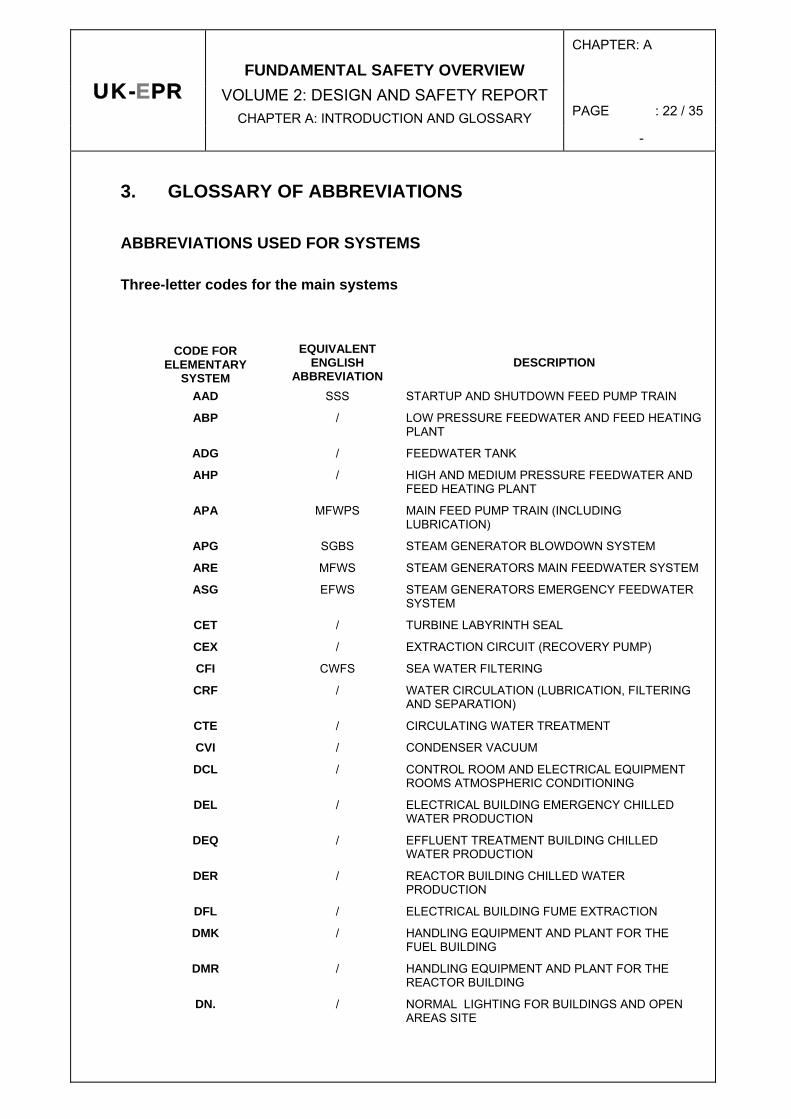
3. GLOSSARY OF ABBREVIATIONS
ABBREVIATIONS USED FOR SYSTEMS
Three-letter codes for the main systems
CODE FOR ELEMENTARY
SYSTEM
EQUIVALENT ENGLISH
ABBREVIATION DESCRIPTION
AAD SSS STARTUP AND SHUTDOWN FEED PUMP TRAIN
ABP / LOW PRESSURE FEEDWATER AND FEED HEATING PLANT
ADG / FEEDWATER TANK
AHP / HIGH AND MEDIUM PRESSURE FEEDWATER AND FEED HEATING PLANT
APA MFWPS MAIN FEED PUMP TRAIN (INCLUDING LUBRICATION)
APG SGBS STEAM GENERATOR BLOWDOWN SYSTEM
ARE MFWS STEAM GENERATORS MAIN FEEDWATER SYSTEM
ASG EFWS STEAM GENERATORS EMERGENCY FEEDWATER SYSTEM
CET / TURBINE LABYRINTH SEAL
CEX / EXTRACTION CIRCUIT (RECOVERY PUMP)
CFI CWFS SEA WATER FILTERING
CRF / WATER CIRCULATION (LUBRICATION, FILTERING AND SEPARATION)
CTE / CIRCULATING WATER TREATMENT
CVI / CONDENSER VACUUM
DCL / CONTROL ROOM AND ELECTRICAL EQUIPMENT ROOMS ATMOSPHERIC CONDITIONING
DEL / ELECTRICAL BUILDING EMERGENCY CHILLED WATER PRODUCTION
DEQ / EFFLUENT TREATMENT BUILDING CHILLED WATER PRODUCTION
DER / REACTOR BUILDING CHILLED WATER PRODUCTION
DFL / ELECTRICAL BUILDING FUME EXTRACTION
DMK / HANDLING EQUIPMENT AND PLANT FOR THE FUEL BUILDING
DMR / HANDLING EQUIPMENT AND PLANT FOR THE REACTOR BUILDING
DN. / NORMAL LIGHTING FOR BUILDINGS AND OPEN AREAS SITE

CHAPTER: A
PAGE : 23 / 35 UK-EPR
FUNDAMENTAL SAFETY OVERVIEW VOLUME 2: DESIGN AND SAFETY REPORT
CHAPTER A: INTRODUCTION AND GLOSSARY -
CODE FOR ELEMENTARY
SYSTEM
EQUIVALENT ENGLISH
ABBREVIATION DESCRIPTION
DNX / POWER OUTLET DISTRIBUTION
DS. / EMERGENCY LIGHTING FOR BUILDINGS AND OPEN AREAS OF SITE
DVB / VENTILATION AND AIR-CONDITIONING OF ADMINISTRATIVE OFFICES
DVD / VENTILATION AND HEATING OF DIESEL BUILDINGS
DVL / VENTILATION OF ELECTRICAL ROOMS IN THE ELECTRICAL BUILDING
DVP / VENTILATION OF THE PUMPING STATION
DWB / VENTILATION OF THE CONTAMINABLE ROOMS IN THE OPERATIONAL PRODUCTION CENTRE
DWK / VENTILATION OF THE FUEL BUILDING
DWL CSBVS VENTILATION FOR THE SAFEGUARD AUXILIARY BUILDING AND THE ELECTRICAL BUILDING
DWN / VENTILATION OF THE NUCLEAR AUXILIARY BUILDING
DWQ / VENTILATION OF THE EFFLUENT TREATMENT BUILDING
DWW / VENTILATION OF CONTAMINABLE ROOMS IN THE ACCESS TOWER
EBA CSVS PURGING OF THE REACTOR BUILDING
EDE AVS ANNULUS VENTILATION SYSTEM
EPP / SEALING AND CONTROL OF CONTAINMENT LEAKS (AIR LOCKS, BUSHINGS, BUFFERS, ETC.)
ETY CGCS CONTAINMENT H2 CONTROL (COMBUSTIBLE GAS COMBUSTION CONTROL)
EVF / INTERNAL CONTAINMENT FILTRATION
EVR CCVS CONTAINMENT COOLING AND VENTILATION
EVU CHRS CONTAINMENT HEAT REMOVAL
GCT MSB MAIN STEAM BYPASS (TO CONDENSER)
GEA / AUXILIARY TRANSFORMER
GEV / POWER TRANSMISSION SYSTEM (INCLUDING STEP DOWN TRANFORMER)
GEX / ALTERNATOR EXCITATION AND REGULATION
GPV / MAIN TURBINE STEAM AND BLOWDOWN SYSTEM
GRE / TURBINE GOVERNING SYSTEM
GRV / ALTERNATOR H2 SUPPLY
GSE / TURBINE SAFETY DEVICES (PROTECTION)
GSS / MOISTURE SEPARATORS/REHEATERS
JAC / CLASSIFIED FIRE-FIGHTING WATER PRODUCTION
JDT FDS FIRE DETECTION
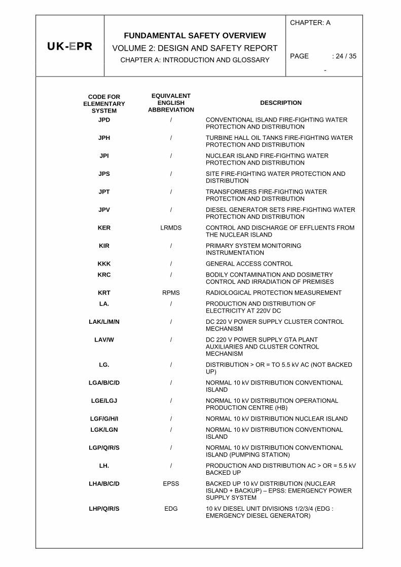
CHAPTER: A
PAGE : 24 / 35 UK-EPR
FUNDAMENTAL SAFETY OVERVIEW VOLUME 2: DESIGN AND SAFETY REPORT
CHAPTER A: INTRODUCTION AND GLOSSARY -
CODE FOR ELEMENTARY
SYSTEM
EQUIVALENT ENGLISH
ABBREVIATION DESCRIPTION
JPD / CONVENTIONAL ISLAND FIRE-FIGHTING WATER PROTECTION AND DISTRIBUTION
JPH / TURBINE HALL OIL TANKS FIRE-FIGHTING WATER PROTECTION AND DISTRIBUTION
JPI / NUCLEAR ISLAND FIRE-FIGHTING WATER PROTECTION AND DISTRIBUTION
JPS / SITE FIRE-FIGHTING WATER PROTECTION AND DISTRIBUTION
JPT / TRANSFORMERS FIRE-FIGHTING WATER PROTECTION AND DISTRIBUTION
JPV / DIESEL GENERATOR SETS FIRE-FIGHTING WATER PROTECTION AND DISTRIBUTION
KER LRMDS CONTROL AND DISCHARGE OF EFFLUENTS FROM THE NUCLEAR ISLAND
KIR / PRIMARY SYSTEM MONITORING INSTRUMENTATION
KKK / GENERAL ACCESS CONTROL
KRC / BODILY CONTAMINATION AND DOSIMETRY CONTROL AND IRRADIATION OF PREMISES
KRT RPMS RADIOLOGICAL PROTECTION MEASUREMENT
LA. / PRODUCTION AND DISTRIBUTION OF ELECTRICITY AT 220V DC
LAK/L/M/N / DC 220 V POWER SUPPLY CLUSTER CONTROL MECHANISM
LAV/W / DC 220 V POWER SUPPLY GTA PLANT AUXILIARIES AND CLUSTER CONTROL MECHANISM
LG. / DISTRIBUTION > OR = TO 5.5 kV AC (NOT BACKED UP)
LGA/B/C/D / NORMAL 10 kV DISTRIBUTION CONVENTIONAL ISLAND
LGE/LGJ / NORMAL 10 kV DISTRIBUTION OPERATIONAL PRODUCTION CENTRE (HB)
LGF/G/H/I / NORMAL 10 kV DISTRIBUTION NUCLEAR ISLAND
LGK/LGN / NORMAL 10 kV DISTRIBUTION CONVENTIONAL ISLAND
LGP/Q/R/S / NORMAL 10 kV DISTRIBUTION CONVENTIONAL ISLAND (PUMPING STATION)
LH. / PRODUCTION AND DISTRIBUTION AC > OR = 5.5 kV BACKED UP
LHA/B/C/D EPSS BACKED UP 10 kV DISTRIBUTION (NUCLEAR ISLAND + BACKUP) – EPSS: EMERGENCY POWER SUPPLY SYSTEM
LHP/Q/R/S EDG 10 kV DIESEL UNIT DIVISIONS 1/2/3/4 (EDG : EMERGENCY DIESEL GENERATOR)
CHAPTER: A
PAGE : 25 / 35 UK-EPR
FUNDAMENTAL SAFETY OVERVIEW VOLUME 2: DESIGN AND SAFETY REPORT
CHAPTER A: INTRODUCTION AND GLOSSARY -
CODE FOR ELEMENTARY
SYSTEM
EQUIVALENT ENGLISH
ABBREVIATION DESCRIPTION
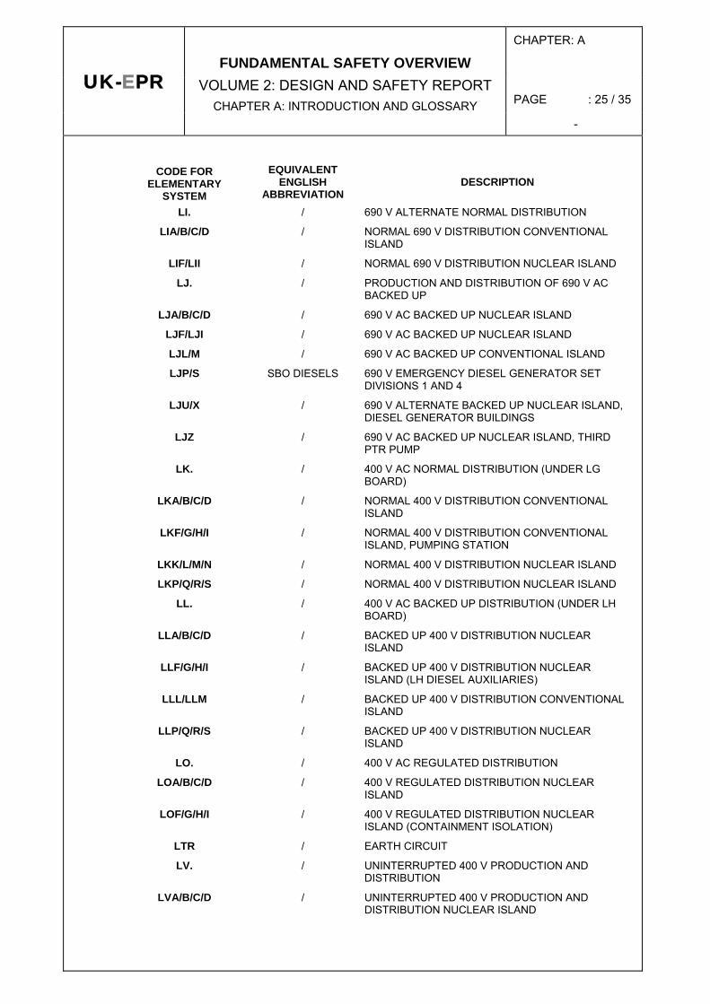
LI. / 690 V ALTERNATE NORMAL DISTRIBUTION
LIA/B/C/D / NORMAL 690 V DISTRIBUTION CONVENTIONAL ISLAND
LIF/LII / NORMAL 690 V DISTRIBUTION NUCLEAR ISLAND
LJ. / PRODUCTION AND DISTRIBUTION OF 690 V AC BACKED UP
LJA/B/C/D / 690 V AC BACKED UP NUCLEAR ISLAND
LJF/LJI / 690 V AC BACKED UP NUCLEAR ISLAND
LJL/M / 690 V AC BACKED UP CONVENTIONAL ISLAND
LJP/S SBO DIESELS 690 V EMERGENCY DIESEL GENERATOR SET DIVISIONS 1 AND 4
LJU/X / 690 V ALTERNATE BACKED UP NUCLEAR ISLAND, DIESEL GENERATOR BUILDINGS
LJZ / 690 V AC BACKED UP NUCLEAR ISLAND, THIRD PTR PUMP
LK. / 400 V AC NORMAL DISTRIBUTION (UNDER LG BOARD)
LKA/B/C/D / NORMAL 400 V DISTRIBUTION CONVENTIONAL ISLAND
LKF/G/H/I / NORMAL 400 V DISTRIBUTION CONVENTIONAL ISLAND, PUMPING STATION
LKK/L/M/N / NORMAL 400 V DISTRIBUTION NUCLEAR ISLAND
LKP/Q/R/S / NORMAL 400 V DISTRIBUTION NUCLEAR ISLAND
LL. / 400 V AC BACKED UP DISTRIBUTION (UNDER LH BOARD)
LLA/B/C/D / BACKED UP 400 V DISTRIBUTION NUCLEAR ISLAND
LLF/G/H/I / BACKED UP 400 V DISTRIBUTION NUCLEAR ISLAND (LH DIESEL AUXILIARIES)
LLL/LLM / BACKED UP 400 V DISTRIBUTION CONVENTIONAL ISLAND
LLP/Q/R/S / BACKED UP 400 V DISTRIBUTION NUCLEAR ISLAND
LO. / 400 V AC REGULATED DISTRIBUTION
LOA/B/C/D / 400 V REGULATED DISTRIBUTION NUCLEAR ISLAND
LOF/G/H/I / 400 V REGULATED DISTRIBUTION NUCLEAR ISLAND (CONTAINMENT ISOLATION)
LTR / EARTH CIRCUIT
LV. / UNINTERRUPTED 400 V PRODUCTION AND DISTRIBUTION
LVA/B/C/D / UNINTERRUPTED 400 V PRODUCTION AND DISTRIBUTION NUCLEAR ISLAND
CHAPTER: A
PAGE : 26 / 35 UK-EPR
FUNDAMENTAL SAFETY OVERVIEW VOLUME 2: DESIGN AND SAFETY REPORT
CHAPTER A: INTRODUCTION AND GLOSSARY -
CODE FOR ELEMENTARY
SYSTEM
EQUIVALENT ENGLISH
ABBREVIATION DESCRIPTION
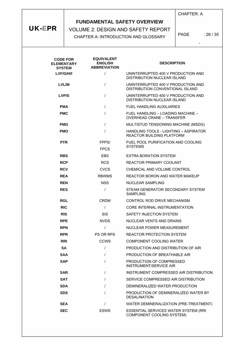
LVF/G/H/I / UNINTERRUPTED 400 V PRODUCTION AND DISTRIBUTION NUCLEAR ISLAND
LVL/M / UNINTERRUPTED 400 V PRODUCTION AND DISTRIBUTION CONVENTIONAL ISLAND
LVP/S / UNINTERRUPTED 400 V PRODUCTION AND DISTRIBUTION NUCLEAR ISLAND
PMA / FUEL HANDLING AUXILIARIES
PMC / FUEL HANDLING – LOADING MACHINE – OVERHEAD CRANE – TRANSFER
PMG / MULTISTUD TENSIONING MACHINE (MSDG)
PMO / HANDLING TOOLS - LIGHTING – ASPIRATOR REACTOR BUILDING PLATFORM
PTR FPPS/
FPCS
FUEL POOL PURIFICATION AND COOLING SYSTEMS
RBS EBS EXTRA BORATION SYSTEM
RCP RCS REACTOR PRIMARY COOLANT
RCV CVCS CHEMICAL AND VOLUME CONTROL
REA RBWMS REACTOR BORON AND WATER MAKEUP
REN NSS NUCLEAR SAMPLING
RES / STEAM GENERATOR SECONDARY SYSTEM SAMPLING
RGL CRDM CONTROL ROD DRIVE MECHANISM
RIC / CORE INTERNAL INSTRUMENTATION
RIS SIS SAFETY INJECTION SYSTEM
RPE NVDS NUCLEAR VENTS AND DRAINS
RPN / NUCLEAR POWER MEASUREMENT
RPR PS OR RPS REACTOR PROTECTION SYSTEM
RRI CCWS COMPONENT COOLING WATER
SA / PRODUCTION AND DISTRIBUTION OF AIR
SAA / PRODUCTION OF BREATHABLE AIR
SAP / PRODUCTION OF COMPRESSED INSTRUMENT/SERVICE AIR
SAR / INSTRUMENT COMPRESSED AIR DISTRIBUTION
SAT / SERVICE COMPRESSED AIR DISTRIBUTION
SDA / DEMINERALIZED WATER PRODUCTION
SDS / PRODUCTION OF DEMINERALIZED WATER BY DESALINATION
SEA / WATER DEMINERALIZATION (PRE-TREATMENT)
SEC ESWS ESSENTIAL SERVICES WATER SYSTEM (RRI COMPONENT COOLING SYSTEM)
CHAPTER: A
PAGE : 27 / 35 UK-EPR
FUNDAMENTAL SAFETY OVERVIEW VOLUME 2: DESIGN AND SAFETY REPORT
CHAPTER A: INTRODUCTION AND GLOSSARY -
CODE FOR ELEMENTARY
SYSTEM
EQUIVALENT ENGLISH
ABBREVIATION DESCRIPTION
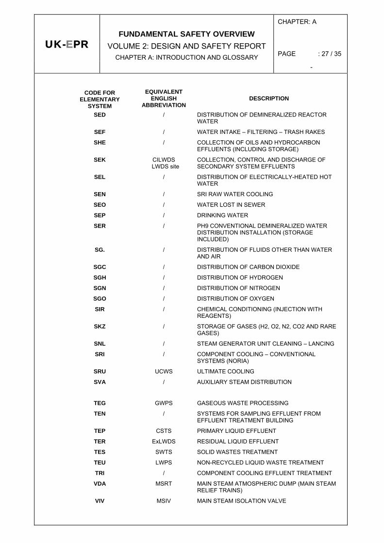
SED / DISTRIBUTION OF DEMINERALIZED REACTOR WATER
SEF / WATER INTAKE – FILTERING – TRASH RAKES
SHE / COLLECTION OF OILS AND HYDROCARBON EFFLUENTS (INCLUDING STORAGE)
SEK CILWDS LWDS site
COLLECTION, CONTROL AND DISCHARGE OF SECONDARY SYSTEM EFFLUENTS
SEL / DISTRIBUTION OF ELECTRICALLY-HEATED HOT WATER
SEN / SRI RAW WATER COOLING
SEO / WATER LOST IN SEWER
SEP / DRINKING WATER
SER / PH9 CONVENTIONAL DEMINERALIZED WATER DISTRIBUTION INSTALLATION (STORAGE INCLUDED)
SG. / DISTRIBUTION OF FLUIDS OTHER THAN WATER AND AIR
SGC / DISTRIBUTION OF CARBON DIOXIDE
SGH / DISTRIBUTION OF HYDROGEN
SGN / DISTRIBUTION OF NITROGEN
SGO / DISTRIBUTION OF OXYGEN
SIR / CHEMICAL CONDITIONING (INJECTION WITH REAGENTS)
SKZ / STORAGE OF GASES (H2, O2, N2, CO2 AND RARE GASES)
SNL / STEAM GENERATOR UNIT CLEANING – LANCING
SRI / COMPONENT COOLING – CONVENTIONAL SYSTEMS (NORIA)
SRU UCWS ULTIMATE COOLING
SVA / AUXILIARY STEAM DISTRIBUTION
TEG GWPS GASEOUS WASTE PROCESSING
TEN / SYSTEMS FOR SAMPLING EFFLUENT FROM EFFLUENT TREATMENT BUILDING
TEP CSTS PRIMARY LIQUID EFFLUENT
TER ExLWDS RESIDUAL LIQUID EFFLUENT
TES SWTS SOLID WASTES TREATMENT
TEU LWPS NON-RECYCLED LIQUID WASTE TREATMENT
TRI / COMPONENT COOLING EFFLUENT TREATMENT
VDA MSRT MAIN STEAM ATMOSPHERIC DUMP (MAIN STEAM RELIEF TRAINS)
VIV MSIV MAIN STEAM ISOLATION VALVE
CHAPTER: A
PAGE : 28 / 35 UK-EPR
FUNDAMENTAL SAFETY OVERVIEW VOLUME 2: DESIGN AND SAFETY REPORT
CHAPTER A: INTRODUCTION AND GLOSSARY -
CODE FOR ELEMENTARY
SYSTEM
EQUIVALENT ENGLISH
ABBREVIATION DESCRIPTION
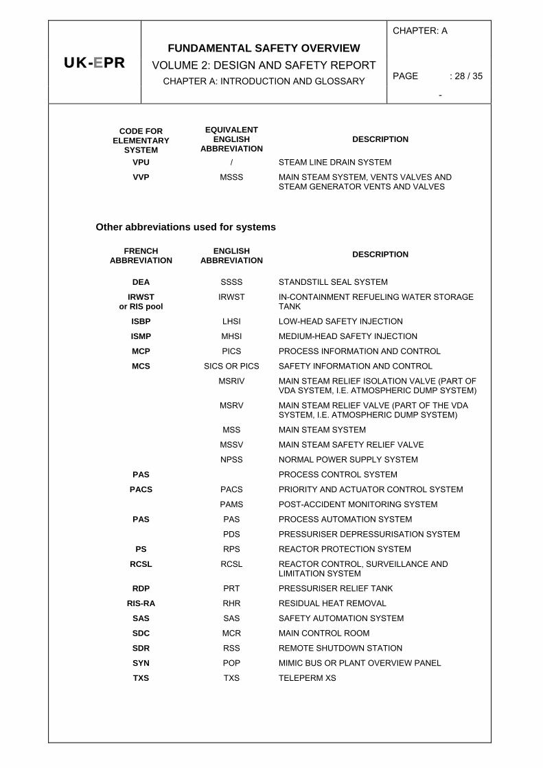
VPU / STEAM LINE DRAIN SYSTEM
VVP MSSS MAIN STEAM SYSTEM, VENTS VALVES AND STEAM GENERATOR VENTS AND VALVES
Other abbreviations used for systems
FRENCH ABBREVIATION
ENGLISH ABBREVIATION
DESCRIPTION
DEA SSSS STANDSTILL SEAL SYSTEM
IRWST or RIS pool
IRWST IN-CONTAINMENT REFUELING WATER STORAGE TANK
ISBP LHSI LOW-HEAD SAFETY INJECTION
ISMP MHSI MEDIUM-HEAD SAFETY INJECTION
MCP PICS PROCESS INFORMATION AND CONTROL
MCS SICS OR PICS SAFETY INFORMATION AND CONTROL
MSRIV MAIN STEAM RELIEF ISOLATION VALVE (PART OF VDA SYSTEM, I.E. ATMOSPHERIC DUMP SYSTEM)
MSRV MAIN STEAM RELIEF VALVE (PART OF THE VDA SYSTEM, I.E. ATMOSPHERIC DUMP SYSTEM)
MSS MAIN STEAM SYSTEM
MSSV MAIN STEAM SAFETY RELIEF VALVE
NPSS NORMAL POWER SUPPLY SYSTEM
PAS PROCESS CONTROL SYSTEM
PACS PACS PRIORITY AND ACTUATOR CONTROL SYSTEM
PAMS POST-ACCIDENT MONITORING SYSTEM
PAS PAS PROCESS AUTOMATION SYSTEM
PDS PRESSURISER DEPRESSURISATION SYSTEM
PS RPS REACTOR PROTECTION SYSTEM
RCSL RCSL REACTOR CONTROL, SURVEILLANCE AND LIMITATION SYSTEM
RDP PRT PRESSURISER RELIEF TANK
RIS-RA RHR RESIDUAL HEAT REMOVAL
SAS SAS SAFETY AUTOMATION SYSTEM
SDC MCR MAIN CONTROL ROOM
SDR RSS REMOTE SHUTDOWN STATION
SYN POP MIMIC BUS OR PLANT OVERVIEW PANEL
TXS TXS TELEPERM XS
CHAPTER: A
PAGE : 29 / 35 UK-EPR
FUNDAMENTAL SAFETY OVERVIEW VOLUME 2: DESIGN AND SAFETY REPORT
CHAPTER A: INTRODUCTION AND GLOSSARY -
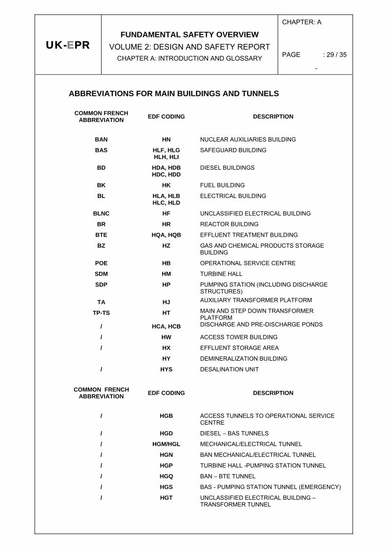
ABBREVIATIONS FOR MAIN BUILDINGS AND TUNNELS
COMMON FRENCH ABBREVIATION EDF CODING DESCRIPTION
BAN HN NUCLEAR AUXILIARIES BUILDING
BAS HLF, HLG HLH, HLI
SAFEGUARD BUILDING
BD HDA, HDB HDC, HDD
DIESEL BUILDINGS
BK HK FUEL BUILDING
BL HLA, HLB HLC, HLD
ELECTRICAL BUILDING
BLNC HF UNCLASSIFIED ELECTRICAL BUILDING
BR HR REACTOR BUILDING
BTE HQA, HQB EFFLUENT TREATMENT BUILDING
BZ HZ GAS AND CHEMICAL PRODUCTS STORAGE BUILDING
POE HB OPERATIONAL SERVICE CENTRE
SDM HM TURBINE HALL
SDP HP PUMPING STATION (INCLUDING DISCHARGE STRUCTURES)
TA HJ AUXILIARY TRANSFORMER PLATFORM
TP-TS HT MAIN AND STEP DOWN TRANSFORMER PLATFORM
/ HCA, HCB DISCHARGE AND PRE-DISCHARGE PONDS
/ HW ACCESS TOWER BUILDING
/ HX EFFLUENT STORAGE AREA
HY DEMINERALIZATION BUILDING
/ HYS DESALINATION UNIT
COMMON FRENCH ABBREVIATION EDF CODING DESCRIPTION
/ HGB ACCESS TUNNELS TO OPERATIONAL SERVICE
CENTRE
/ HGD DIESEL – BAS TUNNELS
/ HGM/HGL MECHANICAL/ELECTRICAL TUNNEL
/ HGN BAN MECHANICAL/ELECTRICAL TUNNEL
/ HGP TURBINE HALL -PUMPING STATION TUNNEL
/ HGQ BAN – BTE TUNNEL
/ HGS BAS - PUMPING STATION TUNNEL (EMERGENCY)
/ HGT UNCLASSIFIED ELECTRICAL BUILDING – TRANSFORMER TUNNEL

CHAPTER: A
PAGE : 30 / 35 UK-EPR
FUNDAMENTAL SAFETY OVERVIEW VOLUME 2: DESIGN AND SAFETY REPORT
CHAPTER A: INTRODUCTION AND GLOSSARY -
COMMON FRENCH ABBREVIATION EDF CODING DESCRIPTION
/ HGW OPERATIONAL SERVICE CENTRE – ACCESS
TOWER TUNNEL
OTHER ABBREVIATIONS (ENGLISH ABBREVIATION NOT GIVEN IF NOT USED OR SAME AS THE SO-CALLED COMMON ABBREVIATION)
COMMON ABBREVIATION
ENGLISH ABBREVIATION DESCRIPTION
AAC HOT SHUTDOWN
AAF COLD SHUTDOWN
AAR AUTOMATIC REACTOR SHUTDOWN
AC ALTERNATING CURRENT
AG SEVERE ACCIDENT
- AP ACTIVATION PRODUCT
AIEA IAEA INTERNATIONAL ATOMIC ENERGY AGENCY
ALARA AS LOW AS REASONABLY ACHIEVABLE
ALARP AS LOW AS REASONABLY PRACTICABLE
APE STATE-ORIENTED APPROACH
API SHUTDOWN FOR MAINTENANCE
APR SHUTDOWN FOR FUEL RELOADING
APRP LOCA LOSS OF PRIMARY COOLANT ACCIDENT
AQ QA QUALITY ASSURANCE
AN/GV NORMAL SHUTDOWN WITH HEAT REMOVAL BY STEAM GENERATORS
AN/RRA NORMAL SHUTDOWN WITH HEAT REMOVAL BY RIS/RRA
AO AXIAL OFFSET
ASR SHUTDOWN FOR SIMPLE RELOADING
ATWS ANTICIPATED TRANSIENT WITHOUT SCRAM
ATWT ANTICIPATED TRANSIENT WITHOUT TRIP
BAE WATER BOX
BC HL HOT LEG
BDOP BASIC DESIGN OPTIMIZATION PHASE
BDR 99 BASIC DESIGN REPORT (EDITION 1999)
BF CL COLD LEG
BI INTERMEDIATE LEG

CHAPTER: A
PAGE : 31 / 35 UK-EPR
FUNDAMENTAL SAFETY OVERVIEW VOLUME 2: DESIGN AND SAFETY REPORT
CHAPTER A: INTRODUCTION AND GLOSSARY -
COMMON ABBREVIATION
ENGLISH ABBREVIATION DESCRIPTION
BNI NUCLEAR ISLAND APART FROM NUCLEAR STEAM SUPPLY SYSTEM (BALANCE OF NUCLEAR ISLAND)
BOP BALANCE OF PLANT (PLANT OUTSIDE CONVENTIONAL AND NUCLEAR ISLANDS)
CAD CAD COMPUTER-AIDED DESIGN
CB BORON CONCENTRATION
CC I&C INSTRUMENTATION AND CONTROL SYSTEM
CDF CORE DAMAGE FREQUENCY
CDU SFC SINGLE FAILURE CRITERION
CIPR ICRP INTERNATIONAL COMMISSION ON RADIOLOGICAL PROTECTION
CNEN NATIONAL CENTRE FOR NUCLEAR EQUIPMENT
CNEPE NATIONAL CENTRE FOR NUCLEAR PRODUCTION EQUIPMENT
CNPE NATIONAL CENTRE FOR ELECTRICITY PRODUCTION
CPP RCPB REACTOR COOLANT PRESSURE BOUNDARY
CREDOC RESEARCH CENTRE FOR THE STUDY AND OBSERVATION OF LIVING CONDITIONS
CSP SSPB SECONDARY SYSTEM PRESSURE BOUNDARY DAC
CREATION AUTHORISATION REQUEST
DARPE AUTHORISATION REQUEST FOR WATER EXTRACTION AND DISCHARGES
DBC DESIGN BASED CONDITION
DC DIRECT CURRENT
DCC CCF COMMON CAUSE FAILURE
DCH DIRECT CONTAINMENT HEATING
DDC BOC BEGINNING OF CYCLE
DDV BOL BEGINNING OF LIFE
DGSNR FRENCH GENERAL DIRECTORATE FOR NUCLEAR SAFETY AND RADIOLOGICAL PROTECTION (DIRECTION GENERALE DE LA SURETE NUCLEAIRE ET DE LA RADIOPROTECTION)
DN NOMINAL DIAMETER
DNB(R) DEPARTURE FROM NUCLEATE BOILING (RATIO)
DT TURBINE TRIP
DT TECHNICAL DIRECTIVES
EDF ELECTRICITE DE FRANCE
ECS EDF CODING SYSTEM
EDS ELECTRICAL DISTRIBUTION SYSTEM
CHAPTER: A
PAGE : 32 / 35 UK-EPR
FUNDAMENTAL SAFETY OVERVIEW VOLUME 2: DESIGN AND SAFETY REPORT
CHAPTER A: INTRODUCTION AND GLOSSARY -
COMMON ABBREVIATION
ENGLISH ABBREVIATION DESCRIPTION
EP PERIODIC TESTS
EPR EUROPEAN PRESSURIZED WATER REACTOR
EPRI ELECTRIC POWER RESEARCH INSTITUTE (USA)
EPS PSA PROBABILISTIC SAFETY ANALYSES
EPW EXPLOSION PRESSURE WAVE
ESP PRESSURE-RETAINING BOUNDARY
ESPN TECHNICAL CODE FOR PRESSURE RETAINING BOUNDARY FOR NUCLEAR EQUIPMENT
ETC-C EPR TECHNICAL CODE FOR CIVIL WORKS
ETC-F EPR TECHNICAL CODE FOR FIRE PROTECTION
EUR EUROPEAN UTILITY REQUIREMENTS
FAC CHAIN FILTER
FAR LBB LEAK BEFORE RUPTURE
FDC EOC END OF CYCLE
FDV EOL END OF LIFE
FH HF HUMAN FACTOR
- FP FISSION PRODUCT
GEMMES - FUEL MANAGEMENT SCHEME FOR 1300MWE ENRICHED UO2 UNITS
GMPP RCP REACTOR COOLANT PUMP
GPR REACTOR SAFETY ADVISORY GROUP OF DGSNR
GV SG STEAM GENERATOR
HEPA HIGH EFFICIENCY PARTICULATE AIR (FILTER)
HTA HVA HIGH VOLTAGE (UP TO 50 kV)
HTB HIGH VOLTAGE (OVER 50 kV)
HVAC HEATING VENTILATION AND AIR CONDITIONING
I&C C&I INSTRUMENTATION AND CONTROL
ICB CCI CORIUM-CONCRETE INTERACTION
ICPE CLASSIFIED INSTALLATION FOR ENVIRONMENTAL PROTECTION
IEG GENERAL ELECTRICAL LAYOUT
IFH HFE HUMAN FACTORS ENGINEERING
IJPP RCPSWI RCP SEAL INJECTION
IHM HMI OR MMI HUMAN-MACHINE INTERFACE
INB BASIC NUCLEAR INSTALLATION (INSTALLATION NUCLEAIRE DE BASE)
INSAG INTERNATIONAL NUCLEAR SAFETY ADVISORY GROUP
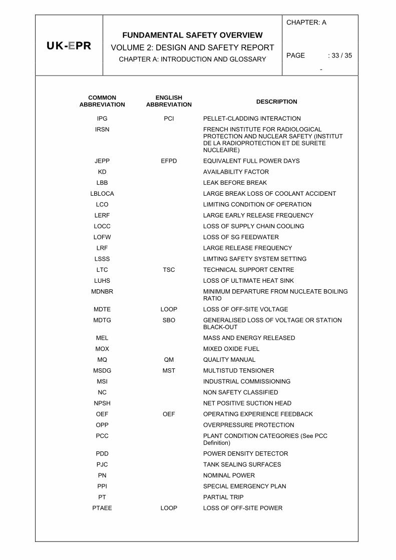
CHAPTER: A
PAGE : 33 / 35 UK-EPR
FUNDAMENTAL SAFETY OVERVIEW VOLUME 2: DESIGN AND SAFETY REPORT
CHAPTER A: INTRODUCTION AND GLOSSARY -
COMMON ABBREVIATION
ENGLISH ABBREVIATION DESCRIPTION
IPG PCI PELLET-CLADDING INTERACTION
IRSN FRENCH INSTITUTE FOR RADIOLOGICAL PROTECTION AND NUCLEAR SAFETY (INSTITUT DE LA RADIOPROTECTION ET DE SURETE NUCLEAIRE)
JEPP EFPD EQUIVALENT FULL POWER DAYS
KD AVAILABILITY FACTOR
LBB LEAK BEFORE BREAK
LBLOCA LARGE BREAK LOSS OF COOLANT ACCIDENT
LCO LIMITING CONDITION OF OPERATION
LERF LARGE EARLY RELEASE FREQUENCY
LOCC LOSS OF SUPPLY CHAIN COOLING
LOFW LOSS OF SG FEEDWATER
LRF LARGE RELEASE FREQUENCY
LSSS LIMTING SAFETY SYSTEM SETTING
LTC TSC TECHNICAL SUPPORT CENTRE
LUHS LOSS OF ULTIMATE HEAT SINK
MDNBR MINIMUM DEPARTURE FROM NUCLEATE BOILING RATIO
MDTE LOOP LOSS OF OFF-SITE VOLTAGE
MDTG SBO GENERALISED LOSS OF VOLTAGE OR STATION BLACK-OUT
MEL MASS AND ENERGY RELEASED
MOX MIXED OXIDE FUEL
MQ QM QUALITY MANUAL
MSDG MST MULTISTUD TENSIONER
MSI INDUSTRIAL COMMISSIONING
NC NON SAFETY CLASSIFIED
NPSH NET POSITIVE SUCTION HEAD
OEF OEF OPERATING EXPERIENCE FEEDBACK
OPP OVERPRESSURE PROTECTION
PCC PLANT CONDITION CATEGORIES (See PCC Definition)
PDD POWER DENSITY DETECTOR
PJC TANK SEALING SURFACES
PN NOMINAL POWER
PPI SPECIAL EMERGENCY PLAN
PT PARTIAL TRIP
PTAEE LOOP LOSS OF OFF-SITE POWER
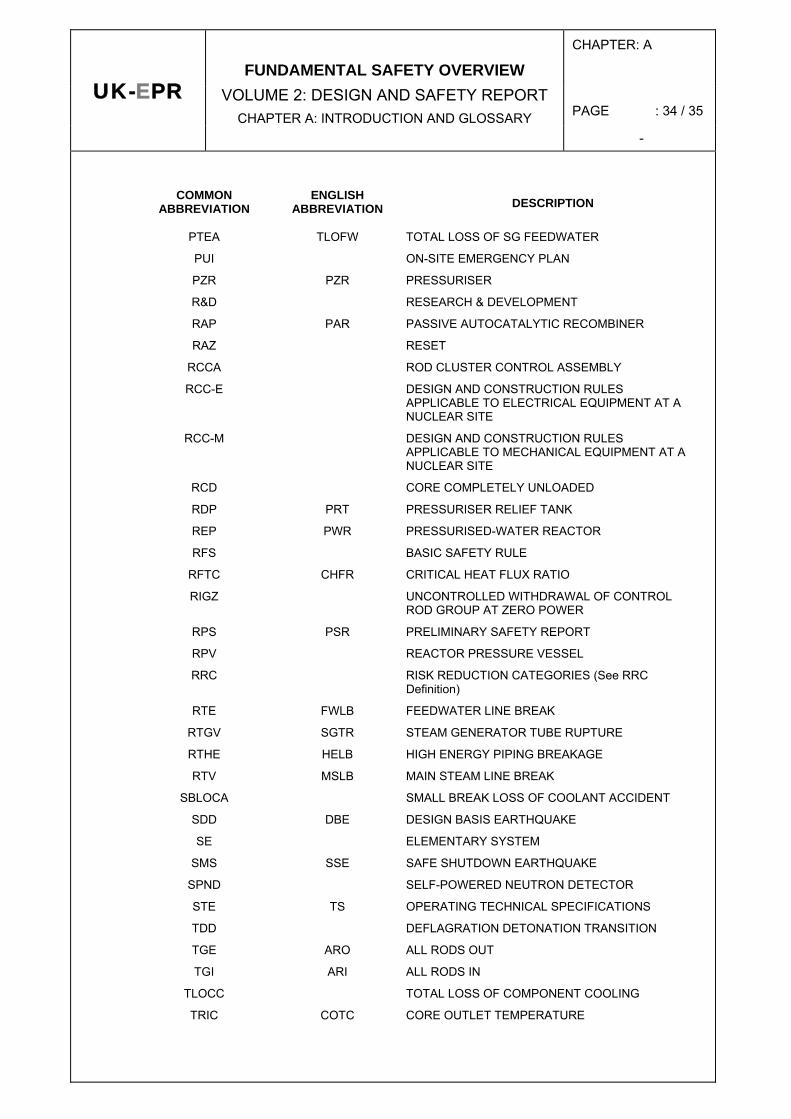
CHAPTER: A
PAGE : 34 / 35 UK-EPR
FUNDAMENTAL SAFETY OVERVIEW VOLUME 2: DESIGN AND SAFETY REPORT
CHAPTER A: INTRODUCTION AND GLOSSARY -
COMMON ABBREVIATION
ENGLISH ABBREVIATION DESCRIPTION
PTEA TLOFW TOTAL LOSS OF SG FEEDWATER
PUI ON-SITE EMERGENCY PLAN
PZR PZR PRESSURISER
R&D RESEARCH & DEVELOPMENT
RAP PAR PASSIVE AUTOCATALYTIC RECOMBINER
RAZ RESET
RCCA ROD CLUSTER CONTROL ASSEMBLY
RCC-E DESIGN AND CONSTRUCTION RULES APPLICABLE TO ELECTRICAL EQUIPMENT AT A NUCLEAR SITE
RCC-M DESIGN AND CONSTRUCTION RULES APPLICABLE TO MECHANICAL EQUIPMENT AT A NUCLEAR SITE
RCD CORE COMPLETELY UNLOADED
RDP PRT PRESSURISER RELIEF TANK
REP PWR PRESSURISED-WATER REACTOR
RFS BASIC SAFETY RULE
RFTC CHFR CRITICAL HEAT FLUX RATIO
RIGZ UNCONTROLLED WITHDRAWAL OF CONTROL ROD GROUP AT ZERO POWER
RPS PSR PRELIMINARY SAFETY REPORT
RPV REACTOR PRESSURE VESSEL
RRC RISK REDUCTION CATEGORIES (See RRC Definition)
RTE FWLB FEEDWATER LINE BREAK
RTGV SGTR STEAM GENERATOR TUBE RUPTURE
RTHE HELB HIGH ENERGY PIPING BREAKAGE
RTV MSLB MAIN STEAM LINE BREAK
SBLOCA SMALL BREAK LOSS OF COOLANT ACCIDENT
SDD DBE DESIGN BASIS EARTHQUAKE
SE ELEMENTARY SYSTEM
SMS SSE SAFE SHUTDOWN EARTHQUAKE
SPND SELF-POWERED NEUTRON DETECTOR
STE TS OPERATING TECHNICAL SPECIFICATIONS
TDD DEFLAGRATION DETONATION TRANSITION
TGE ARO ALL RODS OUT
TGI ARI ALL RODS IN
TLOCC TOTAL LOSS OF COMPONENT COOLING
TRIC COTC CORE OUTLET TEMPERATURE

CHAPTER: A
PAGE : 35 / 35 UK-EPR
FUNDAMENTAL SAFETY OVERVIEW VOLUME 2: DESIGN AND SAFETY REPORT
CHAPTER A: INTRODUCTION AND GLOSSARY -
COMMON ABBREVIATION
ENGLISH ABBREVIATION DESCRIPTION
UCP UPPER CORE PLATE
UPS UNINTERRUPTIBLE POWER SUPPLY
USP UPPER SUPPORT PLATE
VCT VOLUME CONTROL TANK
VD 10-YEARLY IN-SERVICE INSPECTION
VP OUTAGE INSPECTION