Fundamental challenges in electrowetting: from equilibrium shapes to contact angle saturation and...
8
Fundamental challenges in electrowetting: from equilibrium shapes to contact angle saturation and drop dynamics Frieder Mugele * DOI: 10.1039/b904493k Electrowetting is a versatile tool for manipulating typically submillimetre-sized drops in various microfluidic applications. In recent years the microscopic understanding of the electrowetting effect has substantially improved leading to a detailed description of the drop shape and the (singular) distribution of the electric field in the vicinity of the contact line. Based on these findings, novel quantitative models of contact angle saturation, the most important and longstanding fundamental problem in the field, have recently been developed. Future challenges arise in the context of dynamic electrowetting: neither the translational motion of drops nor the generation of internal flow patterns are currently well understood. Introduction Electrowetting is arguably the most flex- ible method to actively control the wetting behavior of conductive liquids on partially wetting surfaces. By applying a voltage between the drop and an elec- trode submerged in the substrate, contact reductions in excess of 90 can be ach- ieved with actuation speeds on the milli- second timescale, determined solely by hydrodynamic response times. Hundreds of thousands of actuation cycles can be applied without any appreciable sign of degradation. The rapidly growing appli- cations of electrowetting (EW) include the areas of optics (e.g. liquid lenses, 1–3 various beam steering devices, 4 reflec- tors), displays, 5–7 reserve batteries, 8,9 as well as lab-on-a-chip systems. 10–12 In the latter area, EW has become the most popular platform for so-called ‘digital’ microfluidic systems that are based on the manipulation of discrete drops in a mi- crofluidic chip. Using a large number of individually addressable electrodes, EW allows for generating, moving, merging, splitting, mixing, etc. of individual drops. Each application area has its own chal- lenges, which are discussed in various specifically targeted review articles in recent years. 5,10,11 For a general review on electrowetting, see ref. 13. In this article, I highlight the recent progress on selected fundamental aspects relevant to all applications of EW. I discuss how EW arises from the interac- tion of conductive liquid drops with externally applied electric fields. Numer- ical calculations of equilibrium drop shapes will be presented describing the distribution of the electric field and its divergence in the vicinity of the contact line. Based on these findings, progress with respect to the longstanding problem of contact angle saturation will be dis- cussed. Finally, I briefly address a few open problems and challenges for the near future: drop dynamics and contact line motion, mixing and internal flow patterns, and novel configurations for electrowetting. Basic electrowetting and its interpretation The electrowetting equation The generic configuration of an electro- wetting setup consists of a sessile drop of a partially wetting conductive liquid on an electrically insulating dielectric layer covering a flat electrode, as shown in Fig. 1. In typical experiments, the drop size ranges from a 0.1 to 1 mm and the dielectric layer has a thickness d between a fraction of a micrometre and a few micrometres. Since electrowetting can only reduce contact angles, one chooses dielectric layers (e.g. fluoropolymers) that display a high contact angle at zero voltage. Upon applying a (not too high) voltage between the electrode on the substrate and the drop the contact angle decreases following the so-called electro- wetting equation Frieder Mugele Prof. Frieder Mugele studied physics and obtained his PhD in physics at the University of Konstanz with Prof. Paul Leiderer. After postdoc and research assistant employments at the Lawrence Berkeley National Laboratory and at the University of Ulm he was ap- pointed Chair of Physics of Complex Fluids at the University of Twente in 2004. In his current research he focuses on three main directions: i) nanofluidics: mechanical studies (Atomic Force Microscopy, Surface Forces Apparatus) of confined molecular fluids. ii) microfluidics and (electro)wetting: two-phase flows and wetting on structured and functionalized surfaces. iii) soft matter mechanics: rheology of complex fluids from colloids to living cells. University of Twente, Physics of Complex Fluids, Enschede, The Netherlands This journal is ª The Royal Society of Chemistry 2009 Soft Matter , 2009, 5, 3377–3384 | 3377 HIGHLIGHT www.rsc.org/softmatter | Soft Matter Published on 01 July 2009. Downloaded by St. Petersburg State University on 14/12/2013 13:04:57. View Article Online / Journal Homepage / Table of Contents for this issue
Transcript of Fundamental challenges in electrowetting: from equilibrium shapes to contact angle saturation and...
HIGHLIGHT www.rsc.org/softmatter | Soft Matter
Publ
ishe
d on
01
July
200
9. D
ownl
oade
d by
St.
Pete
rsbu
rg S
tate
Uni
vers
ity o
n 14
/12/
2013
13:
04:5
7.
View Article Online / Journal Homepage / Table of Contents for this issue
Fundamental challenges in electrowetting:from equilibrium shapes to contact anglesaturation and drop dynamicsFrieder Mugele*
DOI: 10.1039/b904493k
Electrowetting is a versatile tool for manipulating typically submillimetre-sized drops in variousmicrofluidic applications. In recent years the microscopic understanding of the electrowettingeffect has substantially improved leading to a detailed description of the drop shape and the(singular) distribution of the electric field in the vicinity of the contact line. Based on thesefindings, novel quantitative models of contact angle saturation, the most important andlongstanding fundamental problem in the field, have recently been developed. Futurechallenges arise in the context of dynamic electrowetting: neither the translational motion ofdrops nor the generation of internal flow patterns are currently well understood.
Introduction
Electrowetting is arguably the most flex-
ible method to actively control the wetting
behavior of conductive liquids on
partially wetting surfaces. By applying
a voltage between the drop and an elec-
trode submerged in the substrate, contact
reductions in excess of 90� can be ach-
ieved with actuation speeds on the milli-
second timescale, determined solely by
hydrodynamic response times. Hundreds
of thousands of actuation cycles can be
applied without any appreciable sign of
degradation. The rapidly growing appli-
cations of electrowetting (EW) include the
areas of optics (e.g. liquid lenses,1–3
various beam steering devices,4 reflec-
Frieder Mugele
Prof. Frieder
PhD in physi
Paul Leidere
employments
Laboratory a
pointed Cha
University of
focuses on
mechanical s
Forces Appa
microfluidics
wetting on s
soft matter m
colloids to liv
University of Twente, Physics of ComplexFluids, Enschede, The Netherlands
This journal is ª The Royal Society of Chemistry
tors), displays,5–7 reserve batteries,8,9 as
well as lab-on-a-chip systems.10–12 In the
latter area, EW has become the most
popular platform for so-called ‘digital’
microfluidic systems that are based on the
manipulation of discrete drops in a mi-
crofluidic chip. Using a large number of
individually addressable electrodes, EW
allows for generating, moving, merging,
splitting, mixing, etc. of individual drops.
Each application area has its own chal-
lenges, which are discussed in various
specifically targeted review articles in
recent years.5,10,11 For a general review on
electrowetting, see ref. 13.
In this article, I highlight the recent
progress on selected fundamental aspects
relevant to all applications of EW. I
discuss how EW arises from the interac-
tion of conductive liquid drops with
externally applied electric fields. Numer-
Mugele studied physics and obtained his
cs at the University of Konstanz with Prof.
r. After postdoc and research assistant
at the Lawrence Berkeley National
nd at the University of Ulm he was ap-
ir of Physics of Complex Fluids at the
Twente in 2004. In his current research he
three main directions: i) nanofluidics:
tudies (Atomic Force Microscopy, Surface
ratus) of confined molecular fluids. ii)
and (electro)wetting: two-phase flows and
tructured and functionalized surfaces. iii)
echanics: rheology of complex fluids from
ing cells.
2009
ical calculations of equilibrium drop
shapes will be presented describing the
distribution of the electric field and its
divergence in the vicinity of the contact
line. Based on these findings, progress
with respect to the longstanding problem
of contact angle saturation will be dis-
cussed. Finally, I briefly address a few
open problems and challenges for the near
future: drop dynamics and contact line
motion, mixing and internal flow
patterns, and novel configurations for
electrowetting.
Basic electrowetting and itsinterpretation
The electrowetting equation
The generic configuration of an electro-
wetting setup consists of a sessile drop of
a partially wetting conductive liquid on
an electrically insulating dielectric layer
covering a flat electrode, as shown in
Fig. 1. In typical experiments, the drop
size ranges from a 0.1 to 1 mm and the
dielectric layer has a thickness d between
a fraction of a micrometre and a few
micrometres. Since electrowetting can
only reduce contact angles, one chooses
dielectric layers (e.g. fluoropolymers) that
display a high contact angle at zero
voltage. Upon applying a (not too high)
voltage between the electrode on the
substrate and the drop the contact angle
decreases following the so-called electro-
wetting equation
Soft Matter, 2009, 5, 3377–3384 | 3377

Publ
ishe
d on
01
July
200
9. D
ownl
oade
d by
St.
Pete
rsbu
rg S
tate
Uni
vers
ity o
n 14
/12/
2013
13:
04:5
7.
View Article Online
cosq ¼ cosqY + cU2/2s ¼ cosqY + h (1)
in which q and qY are the voltage-depen-
dent contact angle in EW and Young’s
angle of the system at zero voltage,
respectively. s is the interfacial tension
between the drop and the ambient
medium—typically either air or inert oil.
c ¼ 330/d is the capacitance per unit area
between the drop and the electrode on the
substrate (3: dielectric constant of insu-
lator; 30: permittivity of vacuum). The
dimensionless EW number h ¼ cU2/2s
measures the relative strength of electro-
static and surface tension forces in the
system. Fig. 2 illustrates the linear rela-
tion between cosq and h for a series of
drops with variable surface tension. The
collapse of the data shown in the main
panel demonstrates that EW also
provides a convenient way to measure
interfacial tensions for a wide range of
materials, as shown in ref. 14.
Fig. 1 Generic electrowetting setup showing a dro
voltage (solid). The zoomed view shows the bent su
the vicinity of the contact line. Arrows indicate the
Fig. 2 Electrowetting curves. Inset: cosq vs. U2 f
proteins) in ambient oil with increasing interfacial t
Main panel: master curve cosq demonstrating the co
from ref. 14.)
3378 | Soft Matter, 2009, 5, 3377–3384
The EW equation is frequently denoted
as the Young–Lippmann equation
because it can be obtained by combining
Young’s equation, cosqY ¼ (ssv � ssl)/s,
relating the contact angle to the inter-
facial tensions of the system (sv: solid–
vapor; sl: solid–liquid) and Lippmann’s
equation rsl ¼ �vssl/vU (rsl: interfacial
charge density), which yields an effec-
tive reduction of the solid–liquid inter-
facial tension with increasing voltage
according to seffsl (U) ¼ ssl � cU2/2.
Inserting the latter into Young’s equa-
tion leads to eqn (1). This ‘electro-
chemical’ picture of EW is appropriate
on macroscopic scales and provides
correct answers in many practical
considerations on EW. However, when
local properties near the three-phase
contact line matter, as for instance in
the context of contact angle saturation
and contact line motion, a more
detailed description is required.
p at zero voltage (dashed) and with an applied
rface profile and the diverging charge density in
electric field.
or a series of aqueous solutions (surfactants,
ension from 5 to 38 mN/m from top to bottom.
llapse of the data when plotted vs. h. (Adapted
This journ
Equilibrium surface profiles and
electromechanical model of EW
A series of numerical and theoretical
studies15–22 recently addressed this issue. It
was shown that the reduction of the
contact angle in EW can be understood
completely in terms of an electrome-
chanical force balance at the drop surface
while keeping all interfacial tensions
constant. All of these studies follow the
same basic reasoning: the voltage applied
in EW gives rise to electric fringe fields
close to the contact line and thus results in
a Maxwell stress, which pulls on the liquid
surface (see Fig. 1 top). In order to
balance this stress, the shape of the drop
surface has to be curved in such a way that
the Laplace pressure DPL balances the
Maxwell stress pel everywhere along the
surface:
pel ¼3a30
2~Eð~r Þ2¼ 2skð~r Þ ¼ DPL (2)
Here 3a is the dielectric constant of the
ambient medium and k is the local mean
curvature of the drop surface. The calcu-
lations yield the following main results:
(i) the Maxwell stress (and hence the
curvature of the surface) diverges alge-
braically upon approaching the contact
line. This divergence arises from the
‘sharp edge’ or ‘lightning rod’ effect well-
known from basic electrostatics.24 In the
EW geometry, these fields are localized
within a distance of order d from the
contact line. Beyond that, the Maxwell
stress is negligible and the curvature
approaches the asymptotic value corre-
sponding to the global shape of the drop.
(ii) The divergence is sufficiently weak
such that the net force acting on the
contact line vanishes. (iii) Integrating the
horizontal component of the Maxwell
stress over a distance $d yields a net
horizontal force fel ¼ cU2/2. (This result
has in fact been obtained earlier by Jones
using either the stress tensor formalism or
a lumped parameter model.25)
These results imply (i) that the local
contact angle at the contact line is not
affected by the electric fields in EW and
(ii) that the contact angle that does follow
the EW equation is the apparent contact
angle q measured at a distance zd away
from the contact line. This is in contrast
to the electrochemical approach, which
implies a decrease of the local contact
angle because it assumes a voltage-
dependent solid–liquid interfacial
al is ª The Royal Society of Chemistry 2009

Publ
ishe
d on
01
July
200
9. D
ownl
oade
d by
St.
Pete
rsbu
rg S
tate
Uni
vers
ity o
n 14
/12/
2013
13:
04:5
7.
View Article Online
tension. The controversy between the two
competing models can thus be settled by
simultaneously measuring both the local
and the apparent contact angle as a func-
tion of the applied voltage. The length
scale separating local from apparent
behavior is given by d/3, which can be
chosen according to the experimental
needs. Using insulators with a thickness
between 10 and 150 mm, Buehrle and
Mugele23 could visualize the drop surface
down to a scale smaller that d. As shown
in Fig. 3, the global shape of the drop
remains spherical and the apparent
contact angle indeed decreases for all
insulator thicknesses as expected from the
EW equation. For sufficiently thick insu-
lators, however, a clear cross over is
visible from the apparent behavior at
large scales to the local behavior on
a scale <d. As predicted by the numerical
calculations, the drop shape was found to
be consistent with a voltage-independent
local contact angle: the ‘true’ interfacial
tensions is thus indeed independent of the
applied voltage within the experimental
resolution. The contact angle reduction
can thus be explained exclusively in terms
of the electrostatic forces pulling on the
drop surface.
Relation between electromechanical
and electrochemical picture of EW
In order to appreciate the differences
between the two different models of EW,
it is useful to recapitulate the basic steps
Fig. 3 Video snapshots of sessile drops of an aque
lator thickness is d¼ 10, 50, and 150 mm from top to
to right: h¼ 0, 0.5, and 1. Note in particular the diff
the right hand column. (Reproduced with permissio
This journal is ª The Royal Society of Chemistry
of the electrochemical approach. (A very
useful derivation can be found in ref. 26.)
In this approach, one equates the change
in Helmholtz free energy released upon
charging the drop-substrate interface with
the reduction of interfacial tension. For
simple metal–electrolyte interfaces, this
variation is given by the electrostatic
energy involved in charging the electric
double layer. In the typical EW configu-
ration, however, the electrolyte is sepa-
rated from the electrode on the substrate
by the insulating layer (see Fig. 1). In that
case, most of the electrostatic energy
involved in charging the drop-substrate
interface is stored in the insulating layer,
since the capacitance of the latter is typi-
cally three to four orders of magnitude
smaller than the one of the electric double
layer.27 This implies that the ‘true’ (e.g.
water–teflon) solid–liquid interfacial
tension consisting of the chemical contri-
butions and the electrostatic energy
stored in the electric double layer is
constant up to a correction factor of order
3lD/3l d (lD: Debye length; 3l: dielectric
constant of liquid). This automatically
leads to the observed invariance of the
local contact angle. Within the electro-
chemical approach, the total electrostatic
energy is nevertheless incorporated into
an ‘effective’ solid–liquid interfacial
tension, which would more appropriately
be denoted as effective drop-substrate
interfacial tension. Treating the insulating
layer as a part of the composite drop-
substrate interface, the electrochemical
ous salt solution in ambient silicone. The insu-
bottom and the EW number increases from left
erences in drop shape close to the contact line in
n from ref. 23.)
2009
approach describes the physics of the
systems only on scales large compared to
its thickness d. In contrast, the electro-
mechanical picture treats the electrostatic
energy in this layer (or equivalently: the
resulting forces) explicitly. Therefore it
describes the physics of the system both
on scales larger and smaller than d.
The electromechanical picture is thus
the more advanced model: it contains the
predictions of the electrochemical picture
as a limiting case (d / 0) and in addition
it provides predictions about the local
properties in the vicinity of the contact
line, which have been verified experi-
mentally (see Fig. 3). As we will see, these
predictions are crucial for understanding
important practical problems such as
contact angle saturation at high voltage
and contact line dynamics.
Another interesting aspect of the elec-
tromechanical approach has been pointed
out explicitly by Jones:25,28 the total force
fel per unit length of the contact line
experienced by the drop is independent of
the surface profile. The reduction of the
(apparent) contact angle is therefore
‘merely’ a characteristic of the response of
conductive liquids to such forces. This
observation implies that contact angle
saturation does not necessarily limit the
maximum force that can be applied to
a drop.
Contact angle saturation inelectrowetting
The EW equation is generally found to be
fairly well obeyed at low voltage. Above
some system-dependent threshold
voltage, however, contact angle satura-
tion sets in and q eventually becomes
independent of the applied voltage (see
Fig. 4a). For generic materials such as
oxide-covered Si with a (nanometre) thin
hydrophobic top coating the saturation
value of q can be as high as 70–80�, which
is a serious limitation in various applica-
tions. Early observations and tentative
explanations of contact angle saturation
have been discussed in ref. 13. A generally
accepted picture of the phenomenon of
contact angle saturation is still lacking,
yet the recent advances discussed in the
previous section provide important clues.
At first glance, one might suspect that
the divergence of the electric field at the
contact line alone would cause deviations
from the EW equation. Yet, the numerical
Soft Matter, 2009, 5, 3377–3384 | 3379
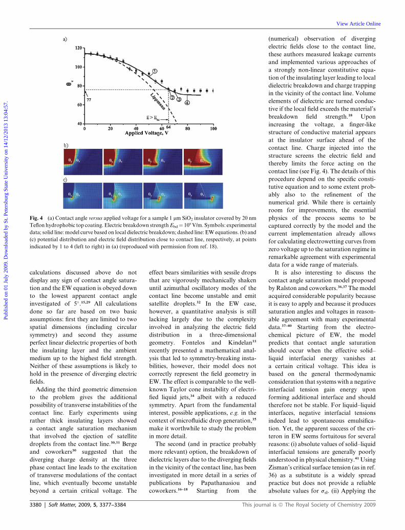
Fig. 4 (a) Contact angle versus applied voltage for a sample 1 mm SiO2 insulator covered by 20 nm
Teflon hydrophobic top coating. Electric breakdown strength Ebd¼ 109 V/m. Symbols: experimental
data; solid line: model curve based on local dielectric breakdown; dashed line: EW equations. (b) and
(c) potential distribution and electric field distribution close to contact line, respectively, at points
indicated by 1 to 4 (left to right) in (a) (reproduced with permission from ref. 18).
Publ
ishe
d on
01
July
200
9. D
ownl
oade
d by
St.
Pete
rsbu
rg S
tate
Uni
vers
ity o
n 14
/12/
2013
13:
04:5
7.
View Article Online
calculations discussed above do not
display any sign of contact angle satura-
tion and the EW equation is obeyed down
to the lowest apparent contact angle
investigated of 5�.15,29 All calculations
done so far are based on two basic
assumptions: first they are limited to two
spatial dimensions (including circular
symmetry) and second they assume
perfect linear dielectric properties of both
the insulating layer and the ambient
medium up to the highest field strength.
Neither of these assumptions is likely to
hold in the presence of diverging electric
fields.
Adding the third geometric dimension
to the problem gives the additional
possibility of transverse instabilities of the
contact line. Early experiments using
rather thick insulating layers showed
a contact angle saturation mechanism
that involved the ejection of satellite
droplets from the contact line.30,31 Berge
and coworkers30 suggested that the
diverging charge density at the three
phase contact line leads to the excitation
of transverse modulations of the contact
line, which eventually become unstable
beyond a certain critical voltage. The
3380 | Soft Matter, 2009, 5, 3377–3384
effect bears similarities with sessile drops
that are vigorously mechanically shaken
until azimuthal oscillatory modes of the
contact line become unstable and emit
satellite droplets.32 In the EW case,
however, a quantitative analysis is still
lacking largely due to the complexity
involved in analyzing the electric field
distribution in a three-dimensional
geometry. Fontelos and Kindelan33
recently presented a mathematical anal-
ysis that led to symmetry-breaking insta-
bilities, however, their model does not
correctly represent the field geometry in
EW. The effect is comparable to the well-
known Taylor cone instability of electri-
fied liquid jets,34 albeit with a reduced
symmetry. Apart from the fundamental
interest, possible applications, e.g. in the
context of microfluidic drop generation,35
make it worthwhile to study the problem
in more detail.
The second (and in practice probably
more relevant) option, the breakdown of
dielectric layers due to the diverging fields
in the vicinity of the contact line, has been
investigated in more detail in a series of
publications by Papathanasiou and
coworkers.16–18 Starting from the
This journ
(numerical) observation of diverging
electric fields close to the contact line,
these authors measured leakage currents
and implemented various approaches of
a strongly non-linear constitutive equa-
tion of the insulating layer leading to local
dielectric breakdown and charge trapping
in the vicinity of the contact line. Volume
elements of dielectric are turned conduc-
tive if the local field exceeds the material’s
breakdown field strength.18 Upon
increasing the voltage, a finger-like
structure of conductive material appears
at the insulator surface ahead of the
contact line. Charge injected into the
structure screens the electric field and
thereby limits the force acting on the
contact line (see Fig. 4). The details of this
procedure depend on the specific consti-
tutive equation and to some extent prob-
ably also to the refinement of the
numerical grid. While there is certainly
room for improvements, the essential
physics of the process seems to be
captured correctly by the model and the
current implementation already allows
for calculating electrowetting curves from
zero voltage up to the saturation regime in
remarkable agreement with experimental
data for a wide range of materials.
It is also interesting to discuss the
contact angle saturation model proposed
by Ralston and coworkers.36,37 The model
acquired considerable popularity because
it is easy to apply and because it produces
saturation angles and voltages in reason-
able agreement with many experimental
data.37–40 Starting from the electro-
chemical picture of EW, the model
predicts that contact angle saturation
should occur when the effective solid–
liquid interfacial energy vanishes at
a certain critical voltage. This idea is
based on the general thermodynamic
consideration that systems with a negative
interfacial tension gain energy upon
forming additional interface and should
therefore not be stable. For liquid–liquid
interfaces, negative interfacial tensions
indeed lead to spontaneous emulsifica-
tion. Yet, the apparent success of the cri-
teron in EW seems fortuitous for several
reasons: (i) absolute values of solid–liquid
interfacial tensions are generally poorly
understood in physical chemistry.41 Using
Zisman’s critical surface tension (as in ref.
36) as a substitute is a widely spread
practice but does not provide a reliable
absolute values for ssl. (ii) Applying the
al is ª The Royal Society of Chemistry 2009

Publ
ishe
d on
01
July
200
9. D
ownl
oade
d by
St.
Pete
rsbu
rg S
tate
Uni
vers
ity o
n 14
/12/
2013
13:
04:5
7.
View Article Online
criterion to the effective interfacial
tension requires a mechanism destabiliz-
ing the solid–liquid interface. So far no
such mechanism has been proposed for
rigid solid surfaces. Effects like the
contact line instability discussed above
may be cast into a negative effective (line)
tension. However, the corresponding
critical voltage will probably be deter-
mined by other criteria than the vanishing
of Lippmann’s effective solid–liquid
interfacial tension. (iii) Finally, and most
importantly, the discussion in the
preceding section showed that the true
solid–liquid interfacial tension does not
change at all in EW.
Overall, the calculations of the micro-
scopic field distributions have improved
our understanding of the EW effect
tremendously. Approaches based on non-
linearities due to the divergence of electric
fields at the contact line such as the one by
Drygiannakis et al.18 seem to capture the
relevant physics of contact angle satura-
tion and are likely to ultimately resolve
this long standing mystery of electro-
wetting. Improving the dielectric strength
and the chemical inertness of the insu-
lating layers will remain the key approach
for achieving better devices. Yet, the
current models also provide some other
clues of how contact angle saturation can
be postponed. The divergence of the
electric field is weaker the larger qY and
ultimately vanishes for qY / p.15 The use
of (very) thick insulators—which is of
course often undesirable for other
reasons—allows for distributing the elec-
tric field over a wider region and should
thereby also postpone contact angle
saturation. The particularly low satura-
tion angle observed on 50 mm thick
Teflon18,30 supports this idea. Petrin22
recently pointed out that the use of
dielectric fluids instead of electrically
conductive ones removes the singularity
for certain values of qY. In view of the
wide variety of (partially non-conductive)
solvents used in lab-on-a-chip devices,42
this option may be of interest in certain
cases. Similarly, the finite penetration
depth of AC electric fields at either high
frequency or low conductivity, which
have been analyzed extensively in the
context of ‘apparent’ contact angle satu-
ration,43–46 also leads to a distribution of
the electric fields over a wider range,
which should help to alleviate the detri-
mental effects of the local fields. Finally,
This journal is ª The Royal Society of Chemistry
the distinction between the contact angle
saturation and maximum electrostatic
force raised by Jones28 opens up another
possible pathway: voltage pulses with an
amplitude beyond the static saturation
voltage but with a duration shorter that
the typical time required for some non-
linear process to develop may allow for
applying higher average forces than the
maximum continuous voltage.
Open frontiers in electrowetting
Drop and contact line dynamics
A quantitative description of the
dynamics of drop motion and the various
other drop manipulation operations such
as drop splitting and merging has been
a long standing concern in EW research.
The dynamics are controlled by the
balance between the driving electrostatic
forces and viscous dissipation. The latter
includes contributions arising from the
bulk and from the moving contact line.
Depending on the ambient conditions,
dynamic EW is either a problem of two-
phase fluid dynamics (ambient oil) or
a problem of motion of a three-phase
contact line (ambient air).
In the former case, several studies
reported that the ambient oil can
become entrapped underneath the
moving drop48–51 leading to smooth,
lubricated contact line motion. Experi-
ments by Staicu and Mugele52 revealed
that the phenomenon can be understood
along the lines of the classical lubrication
flow problems of Landau-Levich and
Bretherton53 The thickness of the
entrapped oil layer was found to be
hzðdffiffiffi
RpÞ2=3ðCa=hÞ2=3, where R is the
three dimensional radius of curvature of
the drop and Ca ¼ mv/s is the capillary
number (m: oil viscosity; v: contact line
velocity). The experiments also showed
that the entrapped oil layers subsequently
break up into drops under the destabiliz-
ing influence of the electric field following
a spinodal dewetting scenario.52
For the problem of EW-driven drop
motion in ambient air, estimates indicate
that the dissipation from the bulk and
from the moving contact line are of the
same order of magnitude.54,55 EW
dynamics is therefore directly related to
the general problem of contact line
motion, which has been a major challenge
in fluid dynamics since the 1970s.56–58
2009
According to classical hydrodynamics the
viscous dissipation diverges in the vicinity
of the moving contact line. This diver-
gence can only be resolved by some
molecular scale process, such as slip at the
solid–liquid interface, disjoining pressure
effects, or local shear thinning. Alterna-
tively, molecular scale hopping processes
such as evaporation and condensation of
liquid have been invoked to explain the
dynamics and dissipation of moving
contact lines.59,60 In addition to these
intrinsic problems, contact angle hyster-
esis and contact line pinning due to
surface heterogeneity poses additional
challenges (see ref. 61 for a review).
Independent of these fundamental prob-
lems, various computational fluid
dynamics studies investigated the basic
processes of drop motion, splitting, and
control.47,62–66 Qualitatively, these studies
typically reproduce the experimentally
observed behavior, as shown in Fig. 5.
Quantitative agreement, however, relies
on empirical correction factors
accounting for the unknown contact line
friction.
Experimentally, it was recently found
that AC voltage dramatically reduces the
effective hysteresis experienced by a drop
in electrowetting.67 Alternating local
electric fields help to detach the contact
line from pinning sites and thereby
mobilize the drop in the same spirit as
mechanical shaking.68 To the extent that
increasingly complex fluids are being
manipulated on increasingly complex
surfaces, a better understanding of
pinning and depinning on heterogeneous
surfaces will become increasingly impor-
tant.
Internal flows and mixing
Efficient mixing is a general concern in
microfluidics.69 In the typical sandwich
configuration of EW-driven lab-on-a-
chip devices, the no-slip boundary
condition on the top and bottom surfaces
produce a parabolic flow profile deep
inside the drop, which leads to mixing due
to Taylor-Aris dispersion.69 To prevent
the time-reversal symmetry of Stokes
flow from cancelling this effect, it has been
suggested to move drops along e.g.
squared or figure eight-shaped closed
paths rather than linearly translating
them back and forth.70,71 Only
recently, the first PIV based analyses of
Soft Matter, 2009, 5, 3377–3384 | 3381

Fig. 5 Drop splitting process in EW device. (a) Experimental data. (b)–(d) Numerical simulation
for decreasing electric driving force (top to bottom). Note the discrepancy in either the absolute
time scale or the drop morphology between simulation and experiment, which is attributed to
contact line friction. (Reproduced with permission from ref. 47.)
Publ
ishe
d on
01
July
200
9. D
ownl
oade
d by
St.
Pete
rsbu
rg S
tate
Uni
vers
ity o
n 14
/12/
2013
13:
04:5
7.
View Article Online
three-dimensional flow fields have been
presented.72,73 In particular for the
increasingly popular configurations of
sessile drops on a single substrate40,76–80
with a large free surface even the origins
of the internal flow patterns are only
poorly understood. In the case of AC-
EW, Ko et al.73 concluded from the
dependence of the observed flow patterns
on the AC frequency and on the salt
concentration that electrokinetic effects
play an important role at high frequency,
whereas low frequency flows were attrib-
uted to hydrodynamic viscous streaming.
Interestingly, however, the low frequency
flow patterns of Ko et al. display the
opposite orientation compared to earlier
dye visualization experiments77 (see
Fig. 6). While these specific differences
may be resolved within the picture of
hydrodynamic streaming, additional
driving mechanisms for internal flows
such as surface tension gradients arising
from either local heating or from
3382 | Soft Matter, 2009, 5, 3377–3384
concentration gradients of surface-active
species81 as well as tangential electrical
stresses82 deserve more attention in the
future.
Alternative approaches in
electrowetting
Two variants of the classical EW config-
uration have attracted some—primarily
theoretical—attention in recent years.
First, Jones et al.83 reported some time
ago the ejection of a liquid finger from
a liquid drop deposited by two parallel
insulator-covered electrodes separated by
a thin slit upon applying high frequency
AC voltage. They explained this
phenomenon in terms of dielectrophoretic
forces. In a series of recent publications,
Yeo et al.84,85 provided a detailed theo-
retical analysis of this phenomenon.
Coupling the electrostatic and the fluid
dynamic problem in lubrication approxi-
mation, they derived scaling relations
This journ
describing the ejection of the liquid finger.
They point out that the high speed of this
actuation method is related to a body
force due to gradients of the electric fields
parallel to the drop surface. In contrast to
the normal electric fields in the standard
EW geometry, these fields do not diverge
upon approaching the contact line, which
might allow for high speed actuation
without dielectric breakdown.
Second, Monroe et al.86–88 theoretically
explored the use of interfaces between two
immiscible electrolytic solutions (ITIES)
for manipulating wetting properties. In
contrast to conventional EW systems, this
approach is based on two conductive
liquids with different dielectric properties
and conductivity. The drop is in direct
contact with a metal electrode and the
electric potential of the ambient fluid is
also externally controlled. The system is
characterized by two back-to-back elec-
tric double layers at the liquid–liquid
interface. The properties of these double
layers can be controlled by varying the
applied potentials. Substantial variations
of the interfacial energies and hence the
contact angles can be achieved upon
applying as little as a few hundred milli-
volts.89 As a consequence of the complex
behavior of the electrolyte solutions, the
contact angle can either increase or
decrease upon applying a voltage and
extremely low contact angles may—at
least in theory—be achieved.
More experimental research to test the
practical usefulness of these two
approaches as well as the predictions of
the models would be desirable.
Conclusions
In summary, detailed analyses of the
electric field distribution in the vicinity of
the three phase contact line in recent years
greatly improved our understanding of
the equilibrium electrowetting effect. The
invariance of the local contact angle upon
applying a voltage as well as the algebraic
divergence of the electric field close to the
contact line have become widely accepted.
Promising approaches to solve the long
standing problem of contact angle satu-
ration have been formulated based on the
non-linear response of the materials
exposed to these high local fields.
With respect to dynamics, important
open issues remain. In particular, the
dynamics of three phase contact lines and
al is ª The Royal Society of Chemistry 2009
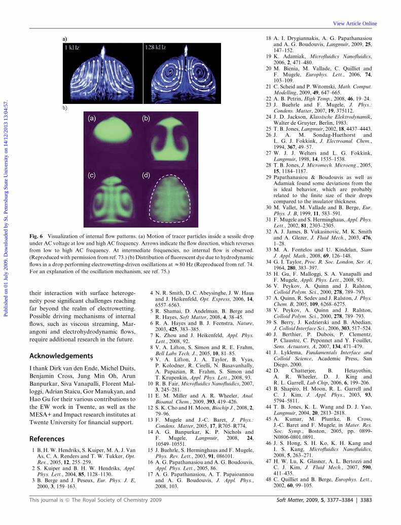
Fig. 6 Visualization of internal flow patterns. (a) Motion of tracer particles inside a sessile drop
under AC voltage at low and high AC frequency. Arrows indicate the flow direction, which reverses
from low to high AC frequency. At intermediate frequencies, no internal flow is observed.
(Reproduced with permission from ref. 73.) (b) Distribution of fluorescent dye due to hydrodynamic
flows in a drop performing electrowetting-driven oscillations at z80 Hz (Reproduced from ref. 74.
For an explanation of the oscillation mechanism, see ref. 75.)
Publ
ishe
d on
01
July
200
9. D
ownl
oade
d by
St.
Pete
rsbu
rg S
tate
Uni
vers
ity o
n 14
/12/
2013
13:
04:5
7.
View Article Online
their interaction with surface heteroge-
neity pose significant challenges reaching
far beyond the realm of electrowetting.
Possible driving mechanisms of internal
flows, such as viscous streaming, Mar-
angoni and electrohydrodynamic flows,
require additional research in the future.
Acknowledgements
I thank Dirk van den Ende, Michel Duits,
Benjamin Cross, Jung Min Oh, Arun
Banpurkar, Siva Vanapalli, Florent Mal-
loggi, Adrian Staicu, Gor Manukyan, and
Hao Gu for their various contributions to
the EW work in Twente, as well as the
MESA+ and Impact research institutes at
Twente University for financial support.
References
1 B. H. W. Hendriks, S. Kuiper, M. A. J. VanAs, C. A. Renders and T. W. Tukker, Opt.Rev., 2005, 12, 255–259.
2 S. Kuiper and B. H. W. Hendriks, Appl.Phys. Lett., 2004, 85, 1128–1130.
3 B. Berge and J. Peseux, Eur. Phys. J. E,2000, 3, 159–163.
This journal is ª The Royal Society of Chemistry
4 N. R. Smith, D. C. Abeysinghe, J. W. Hausand J. Heikenfeld, Opt. Express, 2006, 14,6557–6563.
5 R. Shamai, D. Andelman, B. Berge andR. Hayes, Soft Matter, 2008, 4, 38–45.
6 R. A. Hayes and B. J. Feenstra, Nature,2003, 425, 383–385.
7 K. Zhou and J. Heikenfeld, Appl. Phys.Lett., 2008, 92.
8 V. A. Lifton, S. Simon and R. E. Frahm,Bell Labs Tech. J., 2005, 10, 81–85.
9 V. A. Lifton, J. A. Taylor, B. Vyas,P. Kolodner, R. Cirelli, N. Basavanhally,A. Papazian, R. Frahm, S. Simon andT. Krupenkin, Appl. Phys. Lett., 2008, 93.
10 R. B. Fair, Microfluidics Nanofluidics, 2007,3, 245–281.
11 E. M. Miller and A. R. Wheeler, Anal.Bioanal. Chem., 2009, 393, 419–426.
12 S. K. Cho and H. Moon, Biochip J., 2008, 2,79–96.
13 F. Mugele and J.-C. Baret, J. Phys.:Condens. Matter, 2005, 17, R705–R774.
14 A. G. Banpurkar, K. P. Nichols andF. Mugele, Langmuir, 2008, 24,10549–10551.
15 J. Buehrle, S. Herminghaus and F. Mugele,Phys. Rev. Lett., 2003, 91, 086101.
16 A. G. Papathanasiou and A. G. Boudouvis,Appl. Phys. Lett., 2005, 86.
17 A. G. Papathanasiou, A. T. Papaioannouand A. G. Boudouvis, J. Appl. Phys.,2008, 103.
2009
18 A. I. Drygiannakis, A. G. Papathanasiouand A. G. Boudouvis, Langmuir, 2009, 25,147–152.
19 K. Adamiak, Microfluidics Nanofluidics,2006, 2, 471–480.
20 M. Bienia, M. Vallade, C. Quilliet andF. Mugele, Europhys. Lett., 2006, 74,103–109.
21 C. Scheid and P. Witomski, Math. Comput.Modelling, 2009, 49, 647–665.
22 A. B. Petrin, High Temp., 2008, 46, 19–24.23 J. Buehrle and F. Mugele, J. Phys.:
Condens. Matter, 2007, 19, 375112.24 J. D. Jackson, Klassische Elektrodynamik,
Walter de Gruyter, Berlin, 1983.25 T. B. Jones, Langmuir, 2002, 18, 4437–4443.26 J. A. M. Sondag-Huethorst and
L. G. J. Fokkink, J. Electroanal. Chem.,1994, 367, 49–57.
27 W. J. J. Welters and L. G. Fokkink,Langmuir, 1998, 14, 1535–1538.
28 T. B. Jones, J. Micromech. Microeng., 2005,15, 1184–1187.
29 Papathanasiou & Boudouvis as well asAdamiak found some deviations from theis ideal behavior, which are probablyrelated to the finite size of their dropscompared to the insulator thickness.
30 M. Vallet, M. Vallade and B. Berge, Eur.Phys. J. B, 1999, 11, 583–591.
31 F. Mugele and S. Herminghaus, Appl. Phys.Lett., 2002, 81, 2303–2305.
32 A. J. James, B. Vukasinovic, M. K. Smithand A. Glezer, J. Fluid Mech., 2003, 476,1–28.
33 M. A. Fontelos and U. Kindelan, SiamJ. Appl. Math., 2008, 69, 126–148.
34 G. I. Taylor, Proc. R. Soc. London, Ser. A,1964, 280, 383–397.
35 H. Gu, F. Malloggi, S. A. Vanapalli andF. Mugele, Appli. Phys. Lett., 2008, 93.
36 V. Peykov, A. Quinn and J. Ralston,Colloid Polym. Sci., 2000, 278, 789–793.
37 A. Quinn, R. Sedev and J. Ralston, J. Phys.Chem. B, 2005, 109, 6268–6275.
38 V. Peykov, A. Quinn and J. Ralston,Colloid Polym. Sci., 2000, 278, 789–793.
39 S. Berry, J. Kedzierski and B. Abedian,J. Colloid Interface Sci., 2006, 303, 517–524.
40 J. Berthier, P. Dubois, P. Clementz,P. Claustre, C. Peponnet and Y. Fouillet,Sens. Actuators, A, 2007, 134, 471–479.
41 J. Lyklema, Fundamentals Interface andColloid Science, Academic Press, SanDiego, 2000.
42 D. Chatterjee, B. Hetayothin,A. R. Wheeler, D. J. King andR. L. Garrell, Lab Chip, 2006, 6, 199–206.
43 B. Shapiro, H. Moon, R. L. Garrell andC. J. Kim, J. Appl. Phys., 2003, 93,5794–5811.
44 T. B. Jones, K. L. Wang and D. J. Yao,Langmuir, 2004, 20, 2813–2818.
45 A. Kumar, M. Pluntke, B. Cross,J.-C. Baret and F. Mugele, in Mater. Res.Soc. Symp., Boston, 2005, pp. 0899-N0806-0801.0891.
46 J. S. Hong, S. H. Ko, K. H. Kang andI. S. Kang, Microfluidics Nanofluidics,2008, 5, 263–271.
47 H. W. Lu, K. Glasner, A. L. Bertozzi andC. J. Kim, J. Fluid Mech., 2007, 590,411–435.
48 C. Quilliet and B. Berge, Europhys. Lett.,2002, 60, 99–105.
Soft Matter, 2009, 5, 3377–3384 | 3383

Publ
ishe
d on
01
July
200
9. D
ownl
oade
d by
St.
Pete
rsbu
rg S
tate
Uni
vers
ity o
n 14
/12/
2013
13:
04:5
7.
View Article Online
49 J. S. Kuo, P. Spicar-Mihalic, I. Rodriguezand D. T. Chiu, Langmuir, 2003, 19,250–255.
50 V. Srinivasan, V. K. Pamula and R. B. Fair,Lab Chip, 2004, 4, 310–315.
51 M. Bienia, F. Mugele, C. Quilliet andP. Ballet, Physica A, 2004, 339, 72–79.
52 A. Staicu and F. Mugele, Phys. Rev. Lett.,2006, 97.
53 F. P. Bretherton, J. Fluid Mech., 1961, 10,166.
54 H. Ren, R. B. Fair, M. G. Pollack andE. J. Shaughnessy, Sens. Actuators, B,2002, 87, 201–206.
55 K. L. Wang and T. B. Jones, Langmuir,2005, 21, 4211–4217.
56 C. Huh and L. E. Scriven, J. ColloidInterface Sci., 1971, 35, 85.
57 O. V. Voinov, Fluid Dynamics, 1976, 11,714–721.
58 E. B. Dussan, Ann. Rev. Fluid Mech., 1979,11, 371–400.
59 T. D. Blake and J. M. Haynes, J. ColloidInterface Sci., 1969, 30, 421.
60 T. D. Blake, J. Colloid Interface Sci., 2006,299, 1–13.
61 P. G. deGennes, Rev. Mod. Phys., 1985, 57,827–863.
62 S. W. Walker and B. Shapiro,J. Microelectromech. Syst., 2006, 15,986–1000.
63 S. Walker and B. Shapiro, Lab Chip, 2005,5, 1404–1407.
3384 | Soft Matter, 2009, 5, 3377–3384
64 L. S. Jang, G. H. Lin, Y. L. Lin, C. Y. Hsu,W. H. Kan and C. H. Chen, Biomed.Microdevices, 2007, 9, 777–786.
65 A. Dolatabadi, K. Mohseni andA. Arzpeyma, Can. J. Chem. Eng., 2006,84, 17–21.
66 J. Zeng and T. Korsmeyer, Lab Chip, 2004,4, 265–277.
67 F. Li and F. Mugele, Appl. Phys. Lett.,2008, 92.
68 R. E. Johnson and R. H. Dettre, J. Phys.Chem., 1964, 68, 1744–1750.
69 T. M. Squires and S. R. Quake, Rev. Mod.Phys., 2005, 77, 977–1026.
70 J. Fowler, H. Moon and C. J. Kim, inIEEE Conf. MEMS, Las Vegas, 2002, pp.97–100.
71 P. Paik, V. K. Pamula and R. B. Fair, LabChip, 2003, 3, 253–259.
72 H. W. Lu, F. Bottausci, J. D. Fowler,A. L. Bertozzi, C. Meinhart andC. J. Kim, Lab Chip, 2008, 8, 456–461.
73 S. H. Ko, H. Lee and K. H. Kang,Langmuir, 2008, 24, 1094–1101.
74 F. Mugele, J. C. Baret and D. Steinhauser,Appl. Phys. Lett., 2006, 88.
75 J. C. Baret and F. Mugele, Phys. Rev. Lett.,2006, 96.
76 C. G. Cooney, C. Y. Chen, M. R. Emerling,A. Nadim and J. D. Sterling, MicrofluidicsNanofluidics, 2006, 2, 435–446.
77 F. Mugele, J.-C. Baret and D. Steinhauser,Appl. Phys. Lett., 2006, 88, 204106.
This journ
78 M. Abdelgawad, S. L. S. Freire, H. Yangand A. R. Wheeler, Lab Chip, 2008, 8,672–677.
79 H. L. Ricks-Laskoski, M. A. Buckley andA. W. Snow, J. Appl. Polym. Sci., 2008,110, 3865–3870.
80 K. P. Nichols and H. Gardeniers, Anal.Chem., 2007, 79, 8699–8704.
81 A. A. Darhuber and S. M. Troian, Annu.Rev. Fluid Mech., 2005, 37, 425–455.
82 O. Raccurt, J. Berthier, P. Clementz,M. Borella and M. Plissonnier,J. Micromech. Microeng., 2007, 17,2217–2223.
83 T. B. Jones, M. Gunji, M. Washizu andM. J. Feldman, J. Appl. Phys., 2001, 89,1441–1448.
84 L. Y. Yeo and H. C. Chang, Phys. Rev. E,2006, 73.
85 L. Y. Yeo and H. C. Chang, Mod. Phys.Lett. B, 2005, 19, 549–569.
86 C. W. Monroe, M. Urbakh andA. A. Kornyshev, J. Phys.: Condens.Matter, 2007, 19.
87 C. W. Monroe, L. I. Daikhin, M. Urbakhand A. A. Kornyshev, Phys. Rev. Lett.,2006, 97.
88 C. W. Monroe, L. I. Daikhin, M. Urbakhand A. A. Kornyshev, J. Phys.: Condens.Matter, 2006, 18, 2837–2869.
89 Since there is no insulating layer, it isindeed the ‘true’ interfacial tension thatis varied.
al is ª The Royal Society of Chemistry 2009