Fundamental Aeronautics Program
19
1 National Aeronautics and Space Administration www.nasa.gov Fundamental Aeronautics Program 2012 Technical Conference March 13-15, 2012 Dr. Gary D. Roberts Technical Lead, Advanced Materials RXP/GRC Task Leads: Dr. Robert Miller Mr. Michael Halbig Dr. Christopher Dellacorte Mr. Lee Kohlman Mr. Charles Ruggeri Subsonic Rotary Wing Project Overview of Advanced Materials for Rotorcraft Engines and Drive Systems
Transcript of Fundamental Aeronautics Program

1
National Aeronautics and Space Administration
www.nasa.gov
Fundamental Aeronautics Program
2012 Technical Conference March 13-15, 2012
Dr. Gary D. Roberts Technical Lead, Advanced Materials RXP/GRC Task Leads: Dr. Robert Miller Mr. Michael Halbig Dr. Christopher Dellacorte Mr. Lee Kohlman Mr. Charles Ruggeri
Subsonic Rotary Wing Project
Overview of Advanced Materials for Rotorcraft Engines and Drive Systems
SRW Project Organization
Project Manager: Susan Gorton Deputy Project Manager: Isaac López
Project Scientist: Colin Theodore
Deputy Project Manager For
ARC: Bob Kufeld
Deputy Project Manager For
GRC: Susan Johnson
Deputy Project Manager For
LaRC: Ben Lunsford
Aeromechanics Aeromechanics
Engines & High Temp Materials
Aeromechanics
FD&C
MDATD
Experimental Capabilities: L. Jenkins
Aeromechanics: T. Norman
Engines: J. Welch; G. Roberts
Drive Trains: R. Handschuh
PR
OJE
CT
LEV
EL
SU
B-P
RO
JEC
T LE
VE
L
Flight Dynamics and Control: C. Theodore
Multi-disciplinary Concepts: G. Yamauchi
Business Support Team (Lead Analyst: D. Findley)
Scheduler: J. Moran
Business Support Team (Center Analyst: P. Stacy)
Structures: K. Jackson; K. O’Brien
Acoustics: D. Boyd; R. Cabell
ExCap ExCap
Drive Train & CBM
MDATD
Crashworthiness; D&DT
Ext Acoustics; Cabin Noise
AR
C
GR
C
LaR
C
Technical Challenges
02/08/2012
Business Support Team (Center Analyst: Tony Ou)
2

3
Overview
3
• Engine materials – Update on engine cycle studies
(POC: Dr. Robert Bruckner)
– Erosion resistant thermal barrier coatings (TBC’s) for turbine blades (POC: Dr. Robert Miller)
– Ceramic matrix composites (CMC’s) for turbine vanes and blades (POC: Mr. Michael Halbig)
• Drive system materials and structures – Composite material applications
(POC’s: Mr. Lee Kohlman; Mr. Charles Ruggeri) • Hybrid metal/composite gear • Dynamic test method development
– Super-elastic alloy for bearings (POC: Dr. Christopher Dellacorte)

4
Overview
4
• Engine materials – Update on engine cycle studies – Erosion resistant thermal barrier coatings (TBC’s) for turbine blades – Ceramic matrix composites (CMC’s) for turbine vanes and blades
• Drive system materials and structures – Composite material applications
• Hybrid metal/composite gear • Dynamic test method development
– Super-elastic alloy for bearings

Engine cycle studies
5
• Current work on TBC’s and CMC’s addresses the need for higher T4
• Recent studies indicate that fuel burn continues to improve with OPR ~45 and T4~3200.
• Impeller technologies needed to achieve the required OPR (higher T3) are being considered
T4 T3

Erosion resistant thermal barrier coatings
6
• New TBC’s can enable an additional 200ºF (111ºC) increase in surface temperature compared to current TBC’s, but erosion and impact resistance become a greater issue
• Goal is to improve erosion resistance of coatings and demonstrate performance of the new coatings in future engine tests (SRW project demo tests or industry collaborations)
0 10 20 mm
Data needed before future engine qualification tests • Erosion tests with high fidelity rig • Impact (rig under construction) • Furnace cyclic life • High heat flux performance • Thermal conductivity
FY11 accomplishments • Improved burner rig design produced a more
uniform erosion area in button specimens • 4 new TBC’s were down-selected for further work
(see next chart) • A roadmap was developed to take advantage of
possible future engine test opportunities

Erosion resistant thermal barrier coatings
Composition: • Current TBC’s are 2 component • 4 component coatings have improved erosion resistance with lower thermal conductivity • 6 component coatings should be tougher (Ti and Ta additions), but are harder to deposit by
vapor deposition techniques (vapor pressure differences) Process: • EB-PVD is the baseline process • Directed vapor process has shown promising results for 4 and 6 component compositions • Plasma Spray-PVD has potential, but is currently at low TRL 7

8
Ceramic matrix composites (CMC’s)
8
Joining Performance Requirements • Strength of 25 Mpa • Temperature capability to 1200ºC • Uniform and leak free bonds • FT11 Accomplishments
– Joining approaches developed • Diffusion bonding with Ti and B-Mo metallic foils
– Good bond quality - but requires use of a hot press and flat geometries • Brazing with eutectic phase powders (Si-Cr, Si-Ti, and Si-Hf)
– Paste interlayers gave non-uniform bonds with gaps/voids – Developed a green tape interlayer for brazing (Si-Hf) which gave very
good bonds. Approach down-selected. – Shear strength tests at R.T. and elevated temperatures conducted
Joining of Vane Segments
Joint Microstructures
Joint from Si-Hf tape
SA-Tyrannohex
SA-Tyrannohex
Joint from Si-Hf tape
SiC/SiC
SiC/SiC ROOM TEMP 750° C 1200° C
Substrate Number of Si-Hf Tape Layers
Average Apparent Shear Strength, MPa
Average Apparent Shear Strength, MPa
Average Apparent Shear Strength, MPa
┴ SA -Tyrannohex 1 95.2 (±18.7) 65.6 (±3.4) 75.7 (±13.8)
┴ SA -Tyrannohex 2 102.1 (±15.9) 70.9 (±5.2) 56.9 (±12.1)
Joining of airfoil and endcaps

9
Ceramic matrix composites (CMC’s)
9
• Airfoils fabricated by Hyper-Therm High-Temperature Composites, Inc.
– Material details: two sets of SiC/SiC airfoils with Sylramic and Hi-Nicalon-S SiC fibers, CVI SiC matrix, and SiC foam core
• Challenges include: – Fabrication of a small airfoils: 1”x1”
(vane cord length x height) – Internal cooling schemes and external
film cooling – High inter-laminar strength and robust
leading and trailing edges. • Planned testing
– High pressure burner rig – Laser high heat flux thermal gradient rig
Fabrication Ability of Small CMC High Pressure Turbine Vanes Concept #1 – Internally Cooled Vane
NASA environmental barrier coating applied
1.25” (32mm)
SiC Foam SiC / SiC Composite
Axial Cooling Holes

10
Overview
10
• Engine materials – Update on engine cycle studies – Erosion resistant thermal barrier coatings (TBC’s) for turbine blades – Ceramic matrix composites (CMC’s) for turbine vanes and blades
• Drive system materials and structures – Composite material applications
• Hybrid metal/composite gear • Dynamic test method development
– Super-elastic alloy for bearings

11
Hybrid gear fabrication at A&P Technology
11
Baseline metal spur gear • 12 pitch spur gear (42 teeth) • AISI 9310 gear steel • 25 degree pressure angle • 3.5’’ pitch diameter • ¼’’ face width
0.8847 lb
0.7081 lb (22% reduction)
Hybrid gear (NASA patent pending) 3.5 in
• Contract completed to fabricate small test gears • New SBIR Phase 1 contract awarded for larger gears

12
Hybrid gear testing at NASA
12
Current test results • 300x106 cycles, 553 in-lb torque, 10,000 RPM
with no damage • Possible noise and vibration reduction • Detailed results to be presented
(Handschuh et al., AHS Forum, May 1-3, Ft Worth, TX)
Driving Gear Driven Gear
Accelerometers
Spur gear test rig Loss of oil test (steel gears)
Future plans • Endurance testing to 109 cycles • Torque overload • Single tooth loading • Loss of oil • Large gears

Dynamic test method development Shaft used as a test article in a closed loop gear test rig
13
• Detailed results to be presented (Kohlman et al., AHS Forum, May 1-3, Ft Worth, TX)
• High speed cameras are triggered to capture multiple images per revolution
• Digital image correlation is used to measure deformation
• Pulsed lighting approaches are being developed for better time and spatial resolution

Angular displacement measurements
14
Y (load direction)
X
• Currently working to reduce noise and improve resolution (shutter time, light intensity, lens aperture, pulsed lighting, field of view, static reference)
• Goal is to measure local deformation at resolutions similar to previous work with low speed cameras
-0.50
-0.40
-0.30
-0.20
-0.10
0.00
0.10
0 200 400 600 800 1000
Rot
atio
n an
gle
( Deg
)
Dynamic No-Damage
Dynamic Damage
Static damage
RPM
Torque (in-lb)
5,000 0
0
5,000
10,000 0 0 0
0
Cycle count
Static – undamaged Dynamic – undamaged Dynamic – impact damage
θ Reference point
Strain pattern during a pressurization test observed with low speed cameras
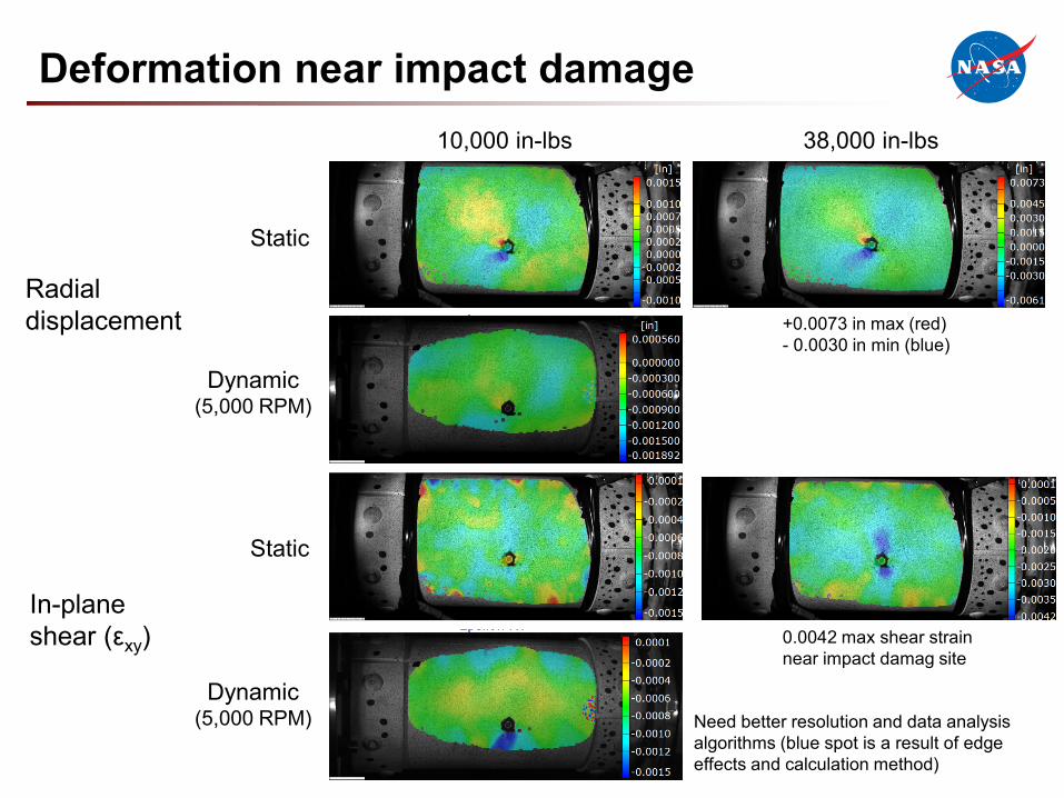
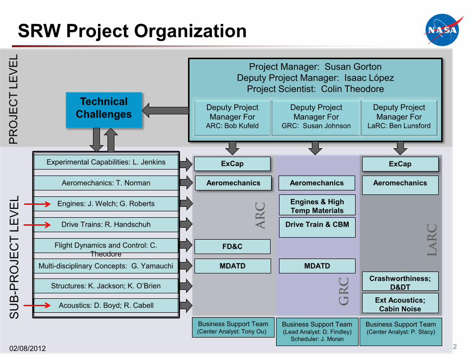
Deformation near impact damage
In-plane shear (εxy)
Radial displacement
10,000 in-lbs 38,000 in-lbs
Static
Dynamic (5,000 RPM)
Static
Dynamic (5,000 RPM)
+0.0073 in max (red) - 0.0030 in min (blue)
0.0042 max shear strain near impact damag site
Need better resolution and data analysis algorithms (blue spot is a result of edge effects and calculation method)

Super-elastic bearing material - NiTiNOL
• Material – Non-ferrous intermetallic, 60NiTi (60wt% Ni + 40wt% Ti) – Invented by W.J. Buehler (late 1950’s) at the Naval Ordinance Laboratory (NiTiNOL
stands for Nickel-Titanium Naval Ordinance Lab) – Similar composition to 55NiTi shape memory alloy
• Key material properties – 15% lighter than steel – Super-elastic (high elastic strain to failure, low modulus) – High hardness – Corrosion resistant
• Potential benefits for bearing performance – Lighter weight – Higher power density – Higher transient load capability – Debris tolerant
16

Super-elastic bearing material • Some critical bearing material requirements
– High hardness (>Rockwell C58) – Wear resistant and compatible with existing lubricants – Resistant to rolling contact fatigue (RCF) – Capable of fabrication into ultra-smooth surfaces – Dimensionally stable and easy to manufacture
17
NiTi-60 NiTi-55 440C M-50
Density (g/cm3) 6.7 6.5 7.7 8.0
Hardness (HRC) 56-62 35-40 58-62 60-65
Young’s modulus (Gpa) 95 100 200 210
Fracture toughness (MPa/m½) TBD TBD 22 20-23
High hardness, low modulus, and high elasticity for NiTi-60are an unusual combination of properties that could resulting in improved bearing performance

Super-elastic bearing material
• Accomplishments for FY11 – Demonstrated 60NiTi and 61 NiTi hardness >62 HRC using heat
treatment above 900ºC – Ongoing investigation of processing methods to achieve a fine
microstructure and minimize precipitates – Performed fabrication trials for bearing smooth, round, straight rods
for measurement of rolling contact fatigue (RCF) • RCF data is critical to evaluate use in highly loaded, high speed,
long duration bearings
18

19 Your Title Here 19