Functionality of Arduino MEGA2560 (REV3) Peripheral Circuitry
2
Functionality of Arduino MEGA2560 (REV3) Peripheral Circuitry Thalagala B.P. 180631J April 29, 2020 The Arduino MEGA2560 is a microcontroller board based on the ATmega2560. It has 54 digital input/output pins (of which 15 can be used as PWM outputs), 16 analog inputs, 4 UARTs (hardware serial ports), a 16 MHz crystal oscillator, a USB connection, a power jack, an ICSP header, and a reset button[1]. Figure 1: Top view of the Arduino MEGA 2560 REV3 board[1] 1 Power Regulator Circuit Power regular circuit is used to regulate the input voltage of the board form a voltage in range of 7V-12V to lower +5V, as this is the operating voltage of the Arduino MEGA board.It consists of following electronic components. Figure 2: Power regulator schematic diagram[1] 1.1 Barrel connector This barrel type connector is used to supply DC power (6V-12V is recommended ) to the board from an external power source. 1.2 Reverse Voltage Protection Diode If the polarity of input supply voltage is accidentally reversed the board may get damaged. This M7 diode (SMD version of 1N4007 diode ) provides the protection at such situations. 1.3 Electrolytic Capacitors Polarized capacitors are used to reduce possible small fluctuations(electrical noise) in the input voltage/current. Capacitors with fairly high capacitance (47μF) is used for this purpose as they can store high electric charge. 1.4 Non-polarized Capacitors Although electrolytic capacitors have high capacitance it is considerably slow in discharging process due to its high series resistance (capacitive reactance). As a solution for this draw back,electrolytic capacitor is discharged through a non-polar capacitor with very low capacitance(100nF) and an extremely small discharging time. 1.5 LD1117S50CTR Voltage Regulator IC This IC continues to work although the input voltage is very close to the required output, and able to handle currents up to 800 mA. Also it can regulate voltages in the range 6.5V to 15V to lower 5V level[3]. 2 Clock Circuit Micro-controllers use clock signal to trigger events and keep track of time as everything happens with respect to time. clock Circuitry is responsible of generating this clock signal which is basically an electronic signal periodically toggle between two states like a Square wave[5]. Figure 3: External oscillator schematic diagram[1] 1
Transcript of Functionality of Arduino MEGA2560 (REV3) Peripheral Circuitry
Functionality of Arduino MEGA2560 (REV3) Peripheral Circuitry
Thalagala B.P. 180631J
April 29, 2020
The Arduino MEGA2560 is a microcontroller boardbased on the ATmega2560. It has 54 digital input/outputpins (of which 15 can be used as PWM outputs), 16analog inputs, 4 UARTs (hardware serial ports), a 16MHz crystal oscillator, a USB connection, a power jack,an ICSP header, and a reset button[1].
Figure 1: Top view of the Arduino MEGA 2560 REV3board[1]
1 Power Regulator Circuit
Power regular circuit is used to regulate the inputvoltage of the board form a voltage in range of 7V-12Vto lower +5V, as this is the operating voltage of theArduino MEGA board.It consists of following electroniccomponents.
Figure 2: Power regulator schematic diagram[1]
1.1 Barrel connector
This barrel type connector is used to supply DC power(6V-12V is recommended) to the board from an externalpower source.
1.2 Reverse Voltage Protection Diode
If the polarity of input supply voltage is accidentallyreversed the board may get damaged. This M7 diode(SMD version of 1N4007 diode) provides the protectionat such situations.
1.3 Electrolytic Capacitors
Polarized capacitors are used to reduce possible smallfluctuations(electrical noise) in the input voltage/current.Capacitors with fairly high capacitance (47µF) is used forthis purpose as they can store high electric charge.
1.4 Non-polarized Capacitors
Although electrolytic capacitors have high capacitanceit is considerably slow in discharging process due toits high series resistance (capacitive reactance). Asa solution for this draw back,electrolytic capacitor isdischarged through a non-polar capacitor with very lowcapacitance(100nF) and an extremely small dischargingtime.
1.5 LD1117S50CTR Voltage Regulator IC
This IC continues to work although the input voltageis very close to the required output, and able to handlecurrents up to 800 mA. Also it can regulate voltages inthe range 6.5V to 15V to lower 5V level[3].
2 Clock Circuit
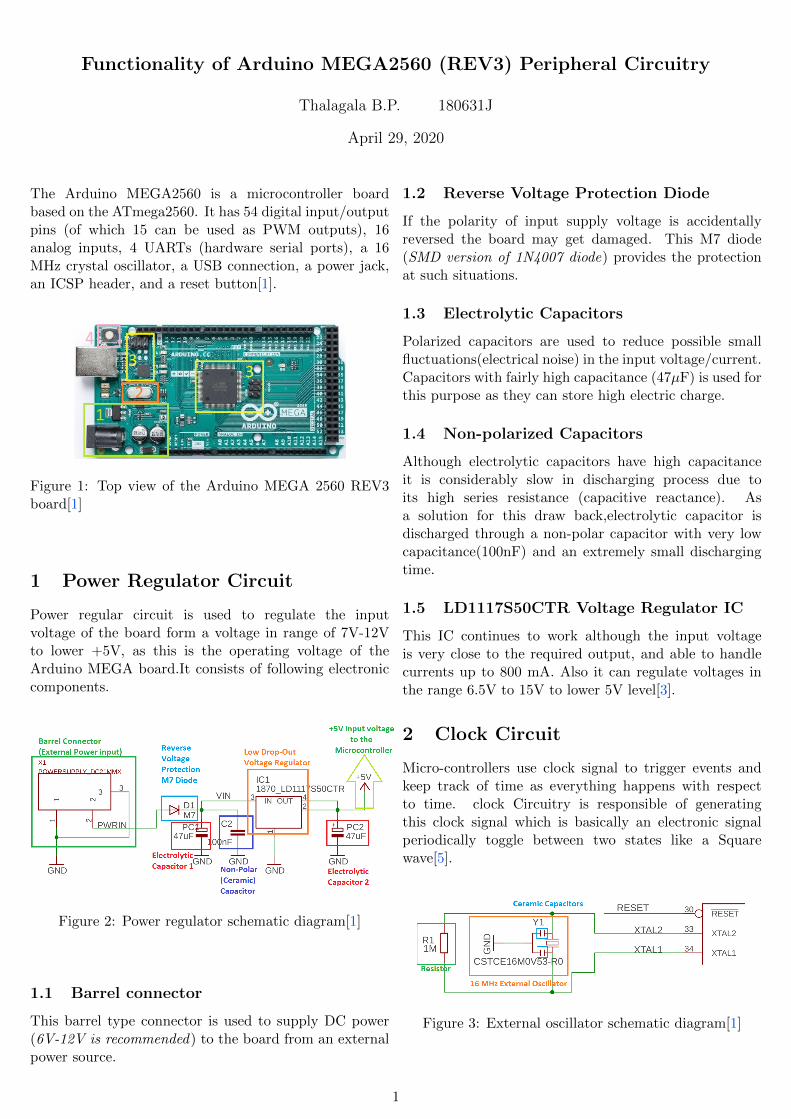
Micro-controllers use clock signal to trigger events andkeep track of time as everything happens with respectto time. clock Circuitry is responsible of generatingthis clock signal which is basically an electronic signalperiodically toggle between two states like a Squarewave[5].
Figure 3: External oscillator schematic diagram[1]
1

2.1 Crystal Oscillator
Arduino MEGA 2560 uses 16 MHz oscillator to generatethis clock signal. It consists of a piezoelectric Crystalresonator [4] and two ceramic capacitors in order to adjustresonance frequency.
3 In-system Programming/In-circuit Serial ProgrammingCircuit
Arduino MEGA2560 board has two ICSP headers namedas ICSP1 and ICSP. Both headers have 6 pins and arearranged in 2 * 3 arrays. 6 pins are named as MISO,MOSI, SCK, V+(+5V), Ground, and Reset[2].
Figure 4: ICSP headers in an Arduino MEGA2560board[1]
3.1 ATMEGA16U2 microcontroller
Programs related to USB to serial conversion are storedhere. This supports to upload the programs into mainATMEGA2560 microcontroller, simply through the USBcable.
3.2 ICSP1
ICSP1 header is used to implement the USB to serialconverter micro-controller(ATMEGA16U2 ).
3.3 ICSP
ICSP header is used to directly program the mainmicrocontroller of the Arduino MEGA2560 board,whenever the USB to serial converter can not beused to program the microcontroller due to anyfailure of converter. To do this additional ISP/ICSPprogrammer(an electronic circuitry) is needed.
4 Reset Circuit
There are two mechanisms to reset the ArduinoMEGA2560 board. One of them is manual while the
other one is done by the USB to serial converter chip.Here the reset pin is active low, i.e. microcontroller getreset whenever the pin receives a low state signal.
4.1 Manual Method
To reset the microcontroller there is a TS42 type pressbutton switch on the board. When it is pressed, reset pinis grounded. This process resets the microcontroller.
Figure 5: Manual resetting[1]
4.2 Reset through the ATMEGA16U2
In this method microcontroller get reset whenever aconnection is made with the Arduino IDE throughits USB cable. The required DTR(Data TerminalReady)signal is sent by the ATMEGA16U2 to the RESETpin of the ATMEGA2560 at the beginning of eachconnecting.
Figure 6: Automatic resetting[1]
Bibliography[1] Arduino Mega 2560 Rev3 | Arduino Official Store. https://store.
arduino.cc/usa/mega-2560-r3.
[2] arduino uno - ICSP pin, what is it actually?https://arduino.stackexchange.com/questions/40098/
icsp-pin-what-is-it-actually.
[3] LD1117xx Datasheet - STMicroelectronics | DigiKey.https://www.digikey.com/en/datasheets/stmicroelectronics/
stmicroelectronics-en-cd00000544#pfd.
[4] Crystal Oscillator : Working and Its VariousApplications. https://www.watelectronics.com/
crystal-oscillator-circuit-working-applications/, September2019.
[5] Wikipedia contributors. Electronic oscillator — Wikipedia, thefree encyclopedia. https://en.wikipedia.org/w/index.php?title=
Electronic_oscillator&oldid=953594751, 2020. [Online; accessed28-April-2020 ].
2