Functional Safety Manual RMA42 - Endress+Hauser
20
Products Solutions Services SD00025R/09/EN/15.14 71251943 Functional Safety Manual RMA42 Process transmitter Application 1- to 2-channel transmitter power supply with intrinsically safe current inputs, temperature inputs, limit value monitoring with 2 changeover contacts, maths functions and 1 to 2 analog outputs that have to meet the particular requirements for safety-related systems in accordance with IEC 61508:2010 (Edition 2.0) and IEC 61511. The measuring unit fulfils the requirements concerning • Functional safety according to IEC 61508:2010 (Edition 2.0) and IEC 61511 • Explosion protection (depending on version) • Electromagnetic compatibility in accordance with EN 61326 and NAMUR recommendation NE 21 • Electrical safety in accordance with IEC/EN 61010-1 Your benefits • Used in a safety-related protection function up to SIL 2, independently assessed and certified by TÜV NORD CERT in accordance with IEC 61508:2010 (Edition 2.0) and IEC 61511:2003 Corrigendum 2004 Chapter 11.4.
Transcript of Functional Safety Manual RMA42 - Endress+Hauser

Products Solutions ServicesSD00025R/09/EN/15.1471251943
Functional Safety ManualRMA42
Process transmitter
Application1- to 2-channel transmitter power supply with intrinsically safe current inputs, temperature inputs, limit value monitoring with 2 changeover contacts, maths functions and 1 to 2 analog outputs that have to meet the particular requirements for safety-related systems in accordance with IEC 61508:2010 (Edition 2.0) and IEC 61511.
The measuring unit fulfils the requirements concerning• Functional safety according to IEC 61508:2010 (Edition 2.0) and IEC 61511• Explosion protection (depending on version)• Electromagnetic compatibility in accordance with EN 61326 and NAMUR
recommendation NE 21• Electrical safety in accordance with IEC/EN 61010-1
Your benefits
• Used in a safety-related protection function up to SIL 2, independently assessed and certified by TÜV NORD CERT in accordance with IEC 61508:2010 (Edition 2.0) and IEC 61511:2003 Corrigendum 2004 Chapter 11.4.


3 Endress+Hauser
RMA42
Table of Contents
SIL Declaration of Conformity . . . . . . . . . . . . . . . . . . . . 4
General information . . . . . . . . . . . . . . . . . . . . . . . . . . . . 5
Measuring system design. . . . . . . . . . . . . . . . . . . . . . . . 5System components . . . . . . . . . . . . . . . . . . . . . . . . . . . . . . . . . . . . 5Description of the application as a safety-instrumented system . 5Permitted device types . . . . . . . . . . . . . . . . . . . . . . . . . . . . . . . . . 5Further applicable device documentation . . . . . . . . . . . . . . . . . . 6
Description of safety requirements and boundary conditions . . . . . . . . . . . . . . . . . . . . . . . . . . . . . . . . . . . . . 6Safety function . . . . . . . . . . . . . . . . . . . . . . . . . . . . . . . . . . . . . . . . 6Safety-related signal . . . . . . . . . . . . . . . . . . . . . . . . . . . . . . . . . . . 7Restrictions for use in safety-related applications . . . . . . . . . . . 7Functional safety parameters . . . . . . . . . . . . . . . . . . . . . . . . . . . . 8Proof-test interval . . . . . . . . . . . . . . . . . . . . . . . . . . . . . . . . . . . . . 9Behavior of device when in operation or in the event of a fault . 9Installation . . . . . . . . . . . . . . . . . . . . . . . . . . . . . . . . . . . . . . . . . . . 9Orientation . . . . . . . . . . . . . . . . . . . . . . . . . . . . . . . . . . . . . . . . . . . 9Operation . . . . . . . . . . . . . . . . . . . . . . . . . . . . . . . . . . . . . . . . . . . . 9Maintenance . . . . . . . . . . . . . . . . . . . . . . . . . . . . . . . . . . . . . . . . . 11
Proof tests . . . . . . . . . . . . . . . . . . . . . . . . . . . . . . . . . . . . 12Procedure for proof test . . . . . . . . . . . . . . . . . . . . . . . . . . . . . . . 12
Repair . . . . . . . . . . . . . . . . . . . . . . . . . . . . . . . . . . . . . . . 12Repair . . . . . . . . . . . . . . . . . . . . . . . . . . . . . . . . . . . . . . . . . . . . . . 12
Appendix . . . . . . . . . . . . . . . . . . . . . . . . . . . . . . . . . . . . . 13Commissioning or proof-test protocol . . . . . . . . . . . . . . . . . . . . 13
TÜV Certificate. . . . . . . . . . . . . . . . . . . . . . . . . . . . . . . . 14
Declaration of Hazardous Material and De-Contamination . . . . . . . . . . . . . . . . . . . . . . . . . . . . . . . . 17

RMA42
4 Endress+Hauser
SIL Declaration of Conformity
SIL-Konformitätserklärung Funktionale Sicherheit nach IEC 61508 / IEC 61511
SIL Declaration of Conformity Functional safety according to IEC 61508 / IEC 61511 Endress+Hauser Wetzer GmbH+Co. KG, Obere Wank 1, 87484 Nesselwang erklärt als Hersteller, dass das Gerät declares as manufacturer, that the device
Seite 1 von 1 Page 1 of 1
RMA42
für den Einsatz in Schutzeinrichtungen entsprechend der IEC 61508 Edition 2.0/IEC 61511 geeignet ist, wenn das Handbuch zur Funktionalen Sicherheit und die Kenngrößen in der folgenden Tabelle beachtet werden: is suitable for the use in safety-instrumented systems according to IEC 61508 Edition 2.0/IEC 61511, if the functional safety manual and the characteristics specified in the following table are observed:
Spannungsausgang / Voltage output x x
Relaisausgang / Relay output x x
Stromausgang / Current output x x
Eingang / Input 1 2 1 2 1 2
Handbuch zur Funktionalen Sicherheit/ Functional safety manual SD00025R
Empfohlenes Intervall für Wiederholungsprüfungen / recommended proof test interval
T1 = 1 Jahr / year
SIL 4) 2
HFT 0
Gerätetyp / Device type B
Betriebsart / Mode Low demand mode
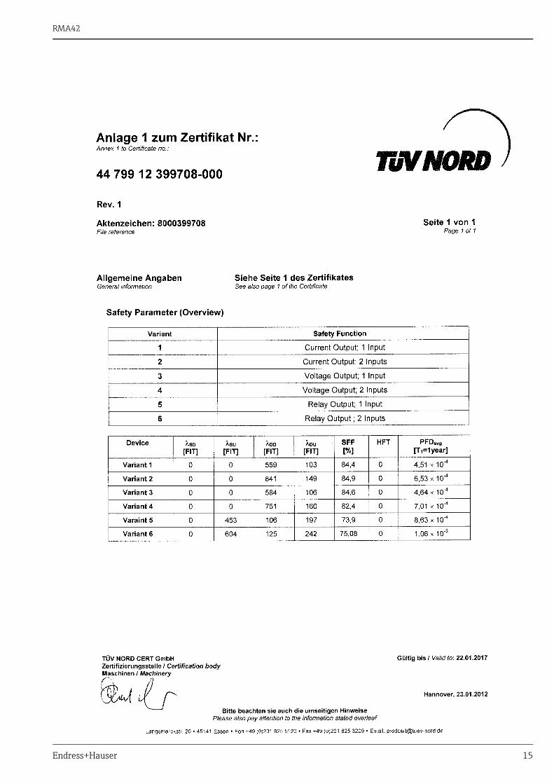
MTBFtot 3) / Jahre / years 95 58 89 60 80 57
SFF 84.4 % 84.9 % 84.6 % 82.4 % 73.9 % 75 %
λSD2) 0 FIT 0 FIT 0 FIT 0 FIT 0 FIT 0 FIT
λSU2) 0 FIT 0 FIT 0 FIT 0 FIT 453 FIT 604 FIT
λDD2) 559 FIT 841 FIT 584 FIT 751 FIT 106 FIT 125 FIT
λDU2) 103 FIT 149 FIT 106 FIT 160 FIT 197 FIT 242 FIT
PFDavg *1) T1 = 1 Jahr / year 4.51 x10⁻⁴ 6.53 x10⁻⁴ 4.64 x10⁻⁴ 7.01 x 10⁻⁴ 8.63 x10⁻⁴ 1.06 x10⁻³
1) Die Werte entsprechen SIL 2 nach ISA S84.01. PFD-Werte für andere T1-Werte siehe Handbuch zur Funktionalen Sicherheit. / The values comply with SIL 2 according to ISA S84.01. PFD values for other T1-values see Functional Safety Manual. 2) Gemäß Siemens SN 29500 / According to Siemens SN 29500 3) Gemäß Siemens SN29500, einschließlich Fehlern, die außerhalb der Sicherheitsfunktion liegen. / According to Siemens SN29500, including faults outside the safety function. 4) Betrachtung gemäß IEC 61511-1 Abschnitt 11.4.4. / Consideration according to IEC 61511-1 clause 11.4.4. Das Gerät einschließlich Software und Änderungsprozess wurde auf Basis der Betriebsbewährung bewertet. The device including the software and the modification process was assessed on the basis of proven-in-use. Nesselwang, 13.03.2012
________________ Wilfried Meissner Chief Executive Officer
SIL-12002b/09/a2

RMA42
Endress+Hauser 5
General informationGeneral information on functional safety (SIL) is available at: www.de.endress.com/SIL (German) or www.endress.com/SIL (English) and in the Competence Brochure CP01008Z "Functional Safety – SIL".
Measuring system design
System components The diagram below displays a measuring system with exemplary devices.
a0012632-en
Part of the process transmitter at the "average probability of failure on demand of a safety-related system" (PFDAVG)
Description of the application as a safety-instrumented system
a0012631-en
Example for "differential pressure" application
Powered by process transmitter RMA42, the sensors generate an analog signal (4 to 20 mA) that is proportional to the measured value. Maths functions enable the generation of a new process variable. The process transmitter sends the analog signals that are proportional to the new process variable to a downstream logic unit, e.g. a PLC. Limit values can also be monitored directly with the RMA42 via 2 changeover contacts.
Permitted device types The functional safety assessment described in this manual applies to the device versions listed below and is valid from the stated software and hardware versions. Valid hardware version (electronics): from 01.00.00Valid firmware software version: from 01.03.03
This document treats the RMA42 as part of a safety function.Together, the sensor, process transmitter, logic unit and actuator form a safety-related system, which carries out a safety function. The "average probability of failure on demand of the entire safety-related system" (PFDavg) is divided among the sensor, process transmitter, logic unit and actuator sub-systems.

RMA42
6 Endress+Hauser
In the event of device modifications, a modification process compliant with IEC 61508 is applied. Unless otherwise indicated, all subsequent versions can also be used for safety-instrumented systems.
Device versions valid for use in safety-related applications:
Further applicable device documentation
Description of safety requirements and boundary conditions
Safety function Description of the safety function performed by the device as part of a safety-instrumented system.An analog output or a limit relay can be used when the device is part of a safety function. The following table shows which settings are permitted or not when the RMA42 is used in a safety-related application:
RMA42 with current or voltage output:
Feature Designation Version
010 Approval All
020 Input; Output All
550 Calibration F1
570 Service All
590 Additional approval H3
620 Accessory All
Documentation Contents Comment
Technical InformationTI00150R/09(RMA42 process transmitter)
• Technical data• Information on accessories
Operating InstructionsBA00287R/09(RMA42 process transmitter)
• Identification• Installation• Wiring• Operation• Commissioning• Maintenance• Accessories• Troubleshooting• Technical data• Appendix: menu diagram
Safety instructions depending on the selected version "Certificate"
• Safety, installation and operating instructions for devices, which are suitable for use in potentially explosive atmospheres or as overfill protection (WHG, German Water Resources Act).
Additional safety instructions (XA, XB, XC, ZE, ZD) are supplied with certified device versions. Please refer to the nameplate for the relevant safety instructions.
Setup menuAnalog Out 1*Analog Out 2*
Setting options(Signal type*)
Setting for safety function
Assignment of analog output(Assignment*)Analog 1*Analog 2*
4 to 20 mA Permitted
0 to 20 mA Not permitted
0 to 10 V Not permitted
2 to 10 V Permitted
0 to 5 V Not permitted
1 to 5 V Not permitted
± 1 V Not permitted

RMA42
Endress+Hauser 7
RMA42 with relay for limit value monitoring:
*) Display in the Setup menu of the device software**) Display in the Expert menu of the device softwareFor further information, refer to the Operating Instructions BA00287R/09.
Safety-related signal The safety-related signal is the 4 to 20 mA or 2-10 V analog output signal or the limit relay.All safety functions solely refer to these output signals.The safety-related output signal or the limit relays are sent to a downstream logic unit, e.g. a programmable logic controller or a limit signal transmitter, and monitored there to establish if:• A specified limit has been overshot• A fault has occurred, e.g. error current in accordance with Namur recommendation 43 (≤ 3.6 mA,
≥ 21.0 mA, signal cable disconnection or short-circuit).
Restrictions for use in safety-related applications
• The measuring system must be used correctly taking into consideration the ambient conditions.• Information on critical process situations and installation conditions from the Operating Instructions
(cf. section 3.2) must be observed.• Application-specific limits must be complied with.• Specifications from the Operating Instructions must not be exceeded. The accuracy of the safety-
related output signal 4 to 20 mA is ± 2% of the measuring range.• Device start-up time: The safety functions are available after an initialization period of 20 seconds
following device start-up.• The device must be locked after configuration.• A complete function test of the safety-related functions must be carried out during commissioning.• Only vertical orientation is permitted.
± 10 V Not permitted
± 30 V Not permitted
± 100 mV Not permitted
30 to 3000 Ohm Not permitted
Response in the event of an error
hold Not permitted
min Permitted
max Permitted
Expert menuOutput**
Setting of response to error event(Failure mode**)
Setting for safety function
Analog Out 1**Analog Out 2**
Fixed value Not permitted
Min Permitted
Max Permitted
Setup menuRelay 1*Relay 2*
Setting options(Function*)
Setting for safety function
Assignment of value to be monitored by relay(Assignment*)Analog input 1*Analog input 2*
Off Not permitted
Min Permitted
Max Permitted
Gradient Permitted
OutBand Permitted
InBand Permitted
Setup menuAnalog Out 1*Analog Out 2*
Setting options(Signal type*)
Setting for safety function

RMA42
8 Endress+Hauser
Functional safety parameters The table shows specific parameters relating to functional safety:
Parameter as per IEC 61508 Value, version 1 Value, version 2 Value, version 3 Value, version 4
Protection function Current output1 input
Current output2 inputs
Voltage output1 input
Voltage output2 inputs
SIL 2 2 2 2
HFT 0 0 0 0
Device type B B B B
Operating mode Low demand mode Low demand mode Low demand mode Low demand mode
MTTR 24 hours 24 hours 24 hours 24 hours
Recommended proof-test interval T1 1 year 1 year 1 year 1 year
SFF 84.4 % 84.9 % 84.6 % 82.4 %
λSD 0 FIT 0 FIT 0 FIT 0 FIT
λSU 0 FIT 0 FIT 0 FIT 0 FIT
λDD 559 FIT 841 FIT 584 FIT 751 FIT
λDU 103 FIT 149 FIT 106 FIT 160 FIT
λTotal *1 662 FIT 990 FIT 690 FIT 911 FIT
PFDavg (for T1 = 1 year) *2 4.51 x 10⁻⁴ 6.53 x 10⁻⁴ 4.64 x 10⁻⁴ 7.01 x 10⁻⁴
MTBF *1 95 years 58 years 89 years 60 years
Fault reaction time *3 5 seconds 5 seconds 5 seconds 5 seconds
Parameter as per IEC 61508 Value, version 5 Value, version 6
Protection function Limit relay1 input
Limit relay2 inputs
SIL 2 2
HFT 0 0
Device type B B
Operating mode Low demand mode Low demand mode
MTTR 24 hours 24 hours
Recommended proof-test interval T1 1 year 1 year
SFF 73.9 % 75.08 %
λSD 0 FIT 0 FIT
λSU 453 FIT 604 FIT
λDD 106 FIT 125 FIT
λDU 197 FIT 242 FIT
λTotal *1 756 FIT 971 FIT
PFDavg (for T1 = 1 year) *2 8.63 x 10⁻⁴ 1.06 x 10⁻³
MTBF *1 80 years 57 years
Fault reaction time *3 5 seconds 5 seconds
*1
*2
*3
This value takes into account all failure types. Failure rates of electronics components in accordance with Siemens SN29500. (see "Management summary - optional")Where the average temperature when in continuous use is in the region of 50°C, a factor of 1.3 should be taken into account. For further information, see
"Management summary - optional".
Time between fault detection and fault reaction.

RMA42
Endress+Hauser 9
Proof-test interval
A0023232-EN
Proof-test interval depending on the PFDavg
Dangerous undetected failures in this scenario
An incorrect output signal that deviates from the actual measured value by more than 2 %, whereby the output signal is still within the range of 4 to 20 mA, is considered to be a dangerous undetected failure.
Operating life of electrical components
The underlying failure rates of electrical components apply within the usable operating life in accordance with
IEC 61508-2:2010, Section 7.4.7.4, Note 3.
Behavior of device when in operation or in the event of a fault
The behavior during operation and in the event of a fault is described in the Operating Instructions BA00287R/09.
Installation Installation, wiring and commissioning of the device are described in the Operating Instructions BA00287R/09.All relay outputs must be protected by a 2 A fuse in order to prevent the contacts from being damaged.
Orientation The permitted orientation of the device is described in Operating Instructions BA00287R/09.
Operation Device behavior when switched on
The device runs through a diagnostic phase of maximum 20 seconds after it is switched on. During this time, the current output is set to error current ≤ 3.6 mA, the voltage output to 0 V and the limit relays are de-energized.Communication via the PC interface is not possible during this diagnostic phase.The output signal can only be viewed as safe on successful completion of the diagnostic function.
Behavior of device in the event of alarms or warnings
Analog output:
A fault exists at the output when the assigned input or maths channel delivers an error status.Failsafe mode of the output can be configured. The following options can be configured:
PF
DA
VG
1 2 3 4 5 6 7 8 9 10
1.20E-02
1.00E-02
8.00E-03
6.00E-03
4.00E-03
2.00E-03
0E+00
Years
Current output Voltage output Relay outputPFDAVG vs. Proof Test Interval
According to DIN EN 61508-2:2011 Note 3N3), longer operating life spans can be reached through suitable measures by the manufacturer and the operator.
Setting Current output Voltage output
Min < 3.6 mA (3.5 mA)1)
1) actual output value
0 V
Max > 21 mA (22 mA)1) 11 V
RMA42
10 Endress+Hauser
Limit relay:
A fault exists when the assigned input or maths channel delivers an error status. The limit relays are de-energized in the event of a fault.
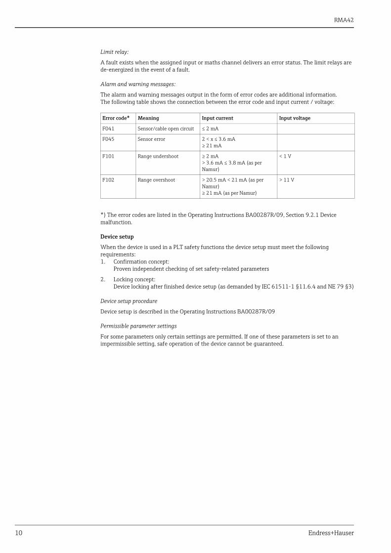
Alarm and warning messages:
The alarm and warning messages output in the form of error codes are additional information.The following table shows the connection between the error code and input current / voltage:
*) The error codes are listed in the Operating Instructions BA00287R/09, Section 9.2.1 Device malfunction.
Device setup
When the device is used in a PLT safety functions the device setup must meet the following requirements:1. Confirmation concept:
Proven independent checking of set safety-related parameters
2. Locking concept:Device locking after finished device setup (as demanded by IEC 61511-1 §11.6.4 and NE 79 §3)
Device setup procedure
Device setup is described in the Operating Instructions BA00287R/09
Permissible parameter settings
For some parameters only certain settings are permitted. If one of these parameters is set to an impermissible setting, safe operation of the device cannot be guaranteed.
Error code* Meaning Input current Input voltage
F041 Sensor/cable open circuit ≤ 2 mA
F045 Sensor error 2 < x ≤ 3.6 mA≥ 21 mA
F101 Range undershoot ≥ 2 mA> 3.6 mA ≤ 3.8 mA (as per Namur)
< 1 V
F102 Range overshoot > 20.5 mA < 21 mA (as per Namur)≥ 21 mA (as per Namur)
> 11 V

RMA42
Endress+Hauser 11
Check
NOTICECheck of the complete safety function is required‣ When all parameters have been set, the safety function must be checked before locking the device!
E.g. using the parameter "Simulation" (→ Operating Instructions BA00287R/09 "Simulation").‣ When the device is used as part of a safety function, the complete safety function must be checked
when the device has been changed, e.g. altered parameter setting.
Locking
CAUTION!
Setup of the device must be locked‣ When all parameters have been set and the safety function been checked, the device must be
locked since changing the measurement system or parameters could be impaired. (→ Section 6.4.6 Operating Instructions BA00287R/09 "Access protection").
Locking the device has to be realized in the following way:• The device has to be protected from unauthorized changes:
User Code protects the set parameters (as in Step 6, → p. 30 in BA00287R/09): Enter 4-digit code: Choose digit with '+' or '-' and confirm the individual digits with 'E';when the digit has been confirmed, the cursor jumps to the next digit or, after the fourth digit, back to the menu item 'System'.The lock symbol is displayed.
• Setup → System → Overfill protect: Select German WHG.
Maintenance No special maintenance work is required on the device.
Function group (menu mapping) Parameter and setting
Expert → Input → Analog In 1/2 → Failure mode Invalid
Expert → Application → Calc value 1/2 → Failure mode Invalid
Expert → Output → Analog output 1/2 → Failure mode MinMax
Expert → Input → Analog In 1/2 → Namur On
Expert → Output → Relay 1/2 → Operating mode norm closed (relay opens when the set point is violated; default setting)
Expert → Output → Relay 1/2 → Failure mode norm closed (relay opens in the event of a fault; default setting)
Expert → Diagnostics → Simulation → Simulation AO1/2
Off
Expert → Diagnostics → Simulation → Simu relay 1/2 Off
Parameter setup using FieldCare PC software via CDI interface requires changing the device status, i.e. WHG must be deactivated in order to change parameters.

RMA42
12 Endress+Hauser
Proof testsSafety functions must be tested at appropriate intervals to ensure that they are functioning correctly and are safe.The intervals must be specified by the operator.The "Proof-test interval depending on the PFDavg" graphic (→ ä 9) can be used for this purpose.The device proof test can be performed as follows:
Procedure for proof test 1. Bypass the logic unit or take other suitable measures to prevent an unwanted reaction in the process.
2. Simulate several defined limit values across the entire range and verify that the output or the limit relays go to a safe state.
3. Restore the complete operational capability of the loop.
4. Disable bypassing of the logic unit or restore normal operation in some other way. This test detects approx. 99% of all possible "du" (dangerous undetected) failures of the RMA42 process transmitter.
Repair
Repair All repairs to the device must be carried out by Endress+Hauser only.Please read the information in the Section "Return" of the appropriate Operating Instructions.
The device may no longer be used as part of a safety-instrumented system if one of the criteria of the test procedures described above is not fulfilled.The proof test is used to detect random device failures. It does not cover the influence of systematic faults on the safety function, which must be checked separately. Operating conditions or corrosion, for example, can cause systematic faults.
In the event of failure of a SIL-labeled E+H device, which has been used in a safety-instrumented system, the "Declaration of Hazardous Material and De-contamination", with the corresponding note "Used as SIL device in a Safety Instrumented System", must be enclosed when the defective device is returned.You will find the "Declaration of Hazardous Material and De-contamination" in the Appendix at the end of this functional safety manual.

RMA42
Endress+Hauser 13
Appendix
Commissioning or proof-test protocol
System-specific data
Company
Measuring points / TAG no.
System
Device type / order code
Serial number of device
Name
Date
Password (if device-specific)
Signature
Device-specific commissioning parameters
Empty value
Full value
Proof test protocol
Test stage Analog output / Limit relay
Set point Actual value
Jumper current input Current: <3.6 mA or > 21 mAVoltage: 0.0 V or 11.0 VRelay: de-energized
Connect multimeter (accuracy class 1) to current/voltage output
Impress a current value of x mA on current input
Read the current/voltage value at the output and record it (set point e.g. x mA +/- 0.1 mA)

RMA42
14 Endress+Hauser
TÜV Certificate
RMA42
Endress+Hauser 15

RMA42
16 Endress+Hauser

RMA42
Endress+Hauser 17
Declaration of Hazardous Material and De-Contamination
RMA42
18 Endress+Hauser

RMA42
Endress+Hauser 19

www.addresses.endress.com