Implementation of Advanced Metering Infrastructure (AMI)/ Smart Metering System Under IPDS
1
Functional Requirements of
Advanced Metering Infrastructure (AMI)
In
India
CENTRAL ELECTRICITY AUTHORITY
August, 2016
2
1 . Functional Requirements for Advanced Metering Infrastructure (AMI) These functional requirements define the minimum functionalities and
performance for AMI system proposed to be developed in India. The main
objective of AMI is to enable two way communication between smart energy meter
and Head End System(HES) to enable remote reading, monitoring & control of
electrical energy meters (consumer, feeder, DT meters etc.) to serve as
repository of record for all raw, validated and edited data. The sanitized data may
be subscribed by other utility function for higher order analysis and billing and
collection engine etc.
2. Basic Functions of AMI
The AMI system shall help utility to manage their resource and business process efficiently. AMI system shall support the following minimum functionalities:
a) Remote Meter data reading at configurable intervals(push/pull)
b) Time of day (TOD)/TOU metering
c) Pre paid functionality
d) Net Metering/Billing
e) Alarm/Event detection, notification and reporting
f) Remote Load Limiter and connection/ disconnection at defined/on demand conditions
g) Remote firmware upgrade
h) Integration with other existing systems like IVRS, Billing & collection software,
GIS mapping, consumer indexing, new connections & disconnection, analysis software, Outage Management System etc.
i) Import of legacy data from existing modules/ MDAS of RAPDRP where ever
possible. The extent and modalities of integration with the existing system including RAPDRP has to be worked out by the bidder.
j) Security features to prevent unauthorized access to the AMI including Smart
meter & meter data etc. and to ensure authentication of all AMI elements by
third party.
This is only an indicative but not exhaustive list. The system should be capable to
support the other functionalities as per the requirement of utilities.
The System should accurately maintain system time synchronization across all
devices to ensure accuracy of data. The system should support the interfacing with
the future Smart Grid functionalities like outage management system, distribution
automation including self-healing system, distribution transformer monitoring units,
Electric vehicle, distributed energy resources etc. The communication network
shall preferably be able to support multiple applications.
3
The Bidder shall submit an approach paper describing overall architecture and
operational philosophy of the proposed AMI solution and methodology for
achieving different functionalities, specified in this document and also highlight
additional features, if any.
3. General AMI System Requirement Smart Meter (Single phase whole current, Three phase whole current, CT & PT
operated three phase meters and CT operated three phase meters) for
consumers/ system shall be provided based on Radio Frequency (RF) mesh in
license free frequency band/ Power Line Carrier Communication (PLCC) or
GPRS/3G/4G communication technology or combination of these technologies as
per the site requirement and to ensure the performance level given in this
document. The smart meter data using RF mesh/PLCC shall be collected by
Data Concentrator Units(DCUs)/Access point and transported to HES through
WAN while the data from smart meters using GPRS/3G/4G technology shall be
transported directly to HES through WAN. The AMI Implementing Agency (AIA)
shall be responsible for proper data exchange among Smart meter, DCU, MDM,
HES and other operational/requisite software as part of fully functional AMI system.
AIA shall adhere with the appropriate security algorithm for encryption and decryption. For smooth functioning of the entire system, it is essential that the details of such algorithm including the mechanism of security key generation be kept in a secured escrow account which shall be used by the utility only in case of termination of the contract for reasons whatsoever.
AIA may design appropriate architecture for providing end to end metering solution. AIA is free to decide upon the best solution out of all the available options. However, the entire responsibility of fully functional AMI system shall rest with one agency i.e. AIA in order to meet the performance levels as given in this document. The communication provider may adopt Radio Frequency (RF) mesh in license free frequency band/ Power Line Carrier Communication (PLCC) or GPRS/3G/4G communication technology or RF based canopy system or a combination of these technologies as per the site requirement adopting best available technology in the proposed area of implementation.
The following core components of AMI system shall be provided:
a) Smart Meters b) Communication infrastructure c) Head End System(HES) d) Meter Data Management System (MDM) e) Web application with updated on-line data of consumers etc. f) Mobile app: AMI Implementing Agency (AIA) shall provide a mobile app through which consumer shall be able to log in through android/iOS/Window based mobile app to see information related to his/her energy consumption. App shall also provide platform for implementation of peak load management functionality by providing existing tariff & incentives rates, participation options etc. This mobile
4
app shall be part of complete system and therefore no additional cost shall be payable for upgradation / maintenance separately. 4. Smart Meters (Single phase & Three phase)
Single Phase & Three Phase whole current smart meters shall comply with the enclosed Technical Specifications. Three Phase CT operated meter shall comply IS 14697 till the relevant IS for CT operated smart meters is available. The supplier / manufacturer would furnish valid BIS certification before supply of meters.
The Smart meter installation shall be done by the AMI Implementing
Agency (AIA) as per the rules and regulations and practices of Utility.
After meter installation, customer identification no., meter ID, its hardware & software configuration, name plate details, make, type i.e. 1 Phase or 3 Phase, etc.( as per requirement of utility) shall be updated in DCU/HES/MDM. The information would also be updated on the portal/app for providing information to consumers. 5. Communication infrastructure
The communication infrastructure should either be based on RF mesh network /
PLC or cellular network or a combination of these. The communication network
shall be based on suitable standards from ITU/IEC/IEEE/CEN/ CENELEC/ ETSI
for NAN and WAN network. Communication network shall provide reliable medium
for two-way communication between various nodes (smart meter) & HES. RF
based network should use license free frequency band available in India. The
engagement of network service provider would be in the scope of AMI
Implementing Agency to meet the performance level as given in the document.
5.1. General Requirement
The AMI Implementing Agency (AIA) shall design a reliable, interference free &
robust communication network keeping in view the site conditions. It shall be
flexible in terms of providing communication in variable terrain & urban density.
The AIA shall design the network architecture keeping in view the existing and
planned infrastructure of the utility. During designing, suitable consideration shall
be kept for future expansion as per requirement of Utility. Before designing the
communication network, the AMI Implementing Agency (AIA) shall do the site
survey and would provide the most efficient communication infrastructure.
The entire infrastructure & associated civil works required for installation &
commissioning of equipment/devices like DCUs, repeaters, routers & access
points etc. shall be in the scope of AMI Implementing Agency (AIA). The
operational testing of all the network elements has to be demonstrated by the
bidder to the satisfaction of the utility.
5
The network solution offered by the bidder should have disaster recovery
mechanism in place. The redundancy mechanism of HES and MDM and their
disaster recovery plan shall also be described by the Bidder.
The quality of installation of the various equipment & power supply wiring to all
field equipment shall be as per standards/ regulations/prevailing practices of the
utility. The supply of electricity needed for operation and maintenance of entire AMI
system shall be the provided by the utility free of cost.
A suitable network management system (NMS) shall be provided to monitor the
performance of the communication network round the clock. The NMS shall
provide viewing of all the networking elements deployed at site and enable
configuration & parameterization of the networking devices and the nodes.
5.2 Network Security The Network shall have adequate cyber security measures not limited to the
measures as described below. The network security would be extended to all the
interfaces also.
Secure Access Controls: The system shall include mechanisms for
defining and controlling user access to the operating system environment and
applications. Best practices from enterprise security including password strength,
password aging, password history, reuse prevention etc. must be followed for
access control.
Authorization Controls: A least-privilege concept such that users are only
allowed to use or access functions for which they have been given authorization
shall be available.
Logging: Logs must be maintained for all attempts to log on (both
successful and unsuccessful), any privilege change requests (both successful and
unsuccessful), user actions affecting security (such as password changes),
attempts to perform actions not authorized by the authorization controls, all
configuration changes etc. Additionally, the access to such logs must be controlled
in accordance to the least-privilege concept mentioned above, so that entries may
not be deleted, accidentally or maliciously.
Hardening: All unnecessary packages must be removed and/or disabled
from the system. Additionally, all unused operating system services and unused
networking ports must be disabled or blocked. Only secure maintenance access
shall be permitted and all known insecure protocols shall be disabled.
Malicious Software Prevention: Implementation of anti-virus software
and other malicious software prevention tools shall be supported for all
applications, servers, data bases etc.
Network Security: The network architecture of the HES must be secure
with support for firewalls and encryption. The system shall also allow host-based
firewalls to be configured, as an additional layer of security if the network firewall
were to fail.
6
5.3. Communication Network Elements (DCU based or Router Based): 5.3.1. Data Concentrator Unit (DCU) based Communication Network
The Data Concentrator Unit is a gateway for communication of data between the
Smart Meters and the HES. The Data Concentrator Unit receives information from
the Smart Meter on a scheduled / need basis and stores the data, which can be
accessed by HES for onward transfer to MDM. The DCU provides the central link between Smart Meters and HES, enabling
continuous/periodic meter read and control. DCU shall exchange data from smart
meters on RF / PLC communication and with HES on WAN.
If communication system is DCU based RF network, then following requirement shall be met. 5.3.1.1 Hardware & Power Supply of DCU
• Enclosure/box of DCU shall be min imum IP55 or bet ter compliant. A
suitable mounting arrangement required for DCU installation shall also be provided. • A suitable and optimum power supply shall be provided keeping in view
that even in case of outage in one or two phases, DCU can be powered. DCU
should be capable of withstanding surges & voltage spikes of 6KV as per IEC
61000-4-5 standards. Power supply shall be terminated on suitable sized MCB
to facilitate isolation during on-site maintenance. • DCU shall have battery with backup for 1 hour for normal meter reading,
to push tamper event, carry out on demand reading and the network health status
/ connectivity continuity & check. DCU should have the suitable feature to send
power outage and restoration message to the HES. The battery shall have a
guaranteed life of 10 years. • DCU shall have built in Real Time Clock (RTC) with separate battery
backup. The battery shall have a guaranteed life of 10 years. It shall have self-
diagnostic feature for RTC, memory, battery, communication module, etc.
Alternatively, Software driven RTC may also be used as per agreement between
supplier and utility.
5.3.1.2 Configuration, Functionality & Interface of DCU DCU shall have following configuration functionalities: • It shall be able to configure the communication with underlying nodes/meters. • It shall pull data from the field devices and push the data at configured intervals
to the HES. It should also support the HES in pulling data from the field devises/meters. The data acquisition (Push/Pull) frequency shall be programmable. DCU shall be capable to prioritize control commands.
• DCU shall ensure a secure communication to HES and shall have internal
memory for storing interval data for at least 5 days. • DCU shall support on demand read and ping of individual/group of meters.
7
• It shall support IPv4 / IPv6 network addressing.
DCU shall push events like tamper, power off etc. to HES immediately on
occurrence/receipt from field devices/meters.
The equipment shall be weatherproof, dustproof and constructed for outdoor
installation on poles (minimum rating: IP-55). A suitable mounting provision shall
be made for the equipment.
Enclosure: Provision for security sealing shall be provided and in case the
gasket of the cover is used for protection against moisture, dust and insects, the
gasket shall be made of weather and aging resistant material.
The list of standards followed in all the devices/equipment used in
communication network shall be furnished
5.3.1.3 DCU Communication • The communication architecture shall be any, as defined under IS 16444.
The DCU shall ensure the appropriate backhaul for secure transfer of data
to HES. In case of GPRS/3G/4G backhaul, it shall support SIM card from any
service provider. It shall have Wide Area Network (WAN) connectivity to the
HES through suitable means.
• DCU shall be able to communicate with meters either on RF mesh (license
free band) or PLC. • DCU shall periodically monitor meter reads/downstream commands and shall
retry and reconnect in case of failed events/reads.
• It shall push events like tamper, power off etc. to HES immediately on occurrence/receipt from field devices/meters. DCU shall be able to acquire and send data to HES for full capacity (as per designed for no. of meters/field devices) to ensure the performance level. Full capacity of DCU is required to be indicated in the offer.
After Power Interruption, on restoration of power supply, DCU shall establish communication with underlying devices as well as upstream application automatically.
• DCU shall be able to communicate with the nearest meters depending on
topographical features. For further communication among the meters, distance
of the other meters with the DCU shall not be a constraint as
communication of the nearest meters shall be established with other meters
through appropriate mesh formation / other formation. • Remote Firmware Upgrade: The DCU shall support remote firmware
upgrades as well as remote configuration from the control center.
Configuration of programmable parameters of smart meters shall be done
through HES.

8
All meters falling under one DCU shall be commissioned and checked for
proper communication in presence of utility in-charge.
DCU shall keep the records of minimum of the following events:
No of packet failures
Retry attempts
Missed periodic readings
Failure to connect
Tamper events
5.3.2 Router based RF Mesh Network If communication system is router based RF mesh network, then following
requirement shall be met. In this type of communication network, different nodes
(smart meters) shall interconnect with each other using RF mesh network and they
shall communicate with nearby routers to transfer the data to access points. In
such communication network, if any routers/repeaters/access points fail, then
nodes connected on that device shall automatically reconfigure the mesh with
available nearby nodes.
5.3.2.1 General Requirement of Router based RF Mesh Network: The general requirements for the Router based RF network are specified below:
i) The communication network shall have dynamic & self-healing capability.
If one of the communication element like router or access point fails then nodes
connecting to that element shall switch to best available element for
communication of data to HES.
ii) It shall support IPv4 / IPv6 network addressing.
iii) Each node shall keep a track of best available nearby nodes.
iv) The communication network equipment shall use licence free frequency
spectrum as defined by Government of India.
v) All the communication network equipment shall be certified by WPC,
Government of India for operation in licence free frequency band.
vi) Suitable network management system (NMS) shall be available to monitor
the performance of the communication network round the clock. The NMS shall
provide viewing of all the networking elements deployed at site and enable
configuration, parameterization of the networking devices and the nodes.
vii) It shall support remote firmware upgrading
viii) It shall be secure enough to avoid all cyber threats like DDoS, spoofing,
malwares etc.
ix) The communication network shall ensure secure communication of data to
HES.
x) The equipment shall be weatherproof, dustproof and constructed for
outdoor installation on poles (minimum rating: IP-55). A suitable mounting
provision shall be made for the equipment.
9
xi) Enclosure: Provision for security sealing shall be provided and in case the
gasket of the cover is used for protection against moisture, dust and insects, the
gasket shall be made of weather and aging resistant material.
xii) The list of standards followed in all the devices/equipment used in
communication network shall be furnished.
xiii) Routers / Access Points shall have suitable power supply arrangements.
Provision of battery backup for at least 1 hour shall be there to continue operation
in case of power supply failure. The life expectancy of battery shall be 5 years or
more.
5.3.2.2 Configuration, Functionality & Interface Access points shall have following configuration functionalities:
It shall be able to configure the communication with underlying nodes/end
points.
It shall support on demand read and ping of individual/group of meters.
It shall push events like tamper, power off etc. to HES immediately on
occurrence/receipt from field devices/meters.
It shall have Wide Area Network (WAN) connectivity to the HES through
suitable means.
It shall communicate with routers/nodes/end points on RF mesh (license
free band).
It shall periodically monitor meter reads/downstream commands and shall
retry and reconnect in case of failed events/reads.
After power Interruption, on restoration of power supply, it shall establish
communication with underlying devices as well as upstream application (HES)
automatically.
Access point shall facilitate recording of
o No of packet failures
o Retry attempts
o Missed periodic reading
o Failure to connect
o Tamper events
It shall be capable to handle interval data of suitable nos. of any type of
smart meter (1ph/3ph). Access point shall be able to acquire and send data to HES
for full capacity (No. of meters/field devices it is designed for) within a suitable time
period to achieve the performance level. Full capacity of access point is required
to be indicated in the offer.
Access point shall support remote firmware upgrades as well as remote
configuration from the control center.
10
5.3.3 Testing of the DCU /Access Point
DCU/Access Point shall be tested for the following:
Radio interference measurement (CIS PR 22)
Surge test (IEC 610004-5)
Fast transient burst test (IEC 61000-4-4)
Test of immunity to electrostatic discharges (IEC 61000-4-2)
Test of immunity to electromagnetic HF field (IEC 61000-4-3)
Resistance to heat and fire
The bidder shall provide IP-55 compliance test certificate for DUC/Access Point.
6. Head End System (HES) The main objective of HES is to acquire meter data automatically avoiding any
human intervention and monitor parameters acquired from meters.
The AMI Implementing Agency (AIA) shall provide the HES suitable to support the
collection and storage of data as per performance level for a defined no. of smart
meters with facility of future expansion as per the requirement of the utility.
(NOTE: The no of smart meters/future expansion may be provided by utility as per
their requirement) HES would perform all the requisite functions as per the defined functionalities of AMI and i t is the responsibility of the AMI Implementing Agency (AIA)/ System Integrator to supply the requisite software and hardware to achieve the defined functionalities of AMI. HES shall ensure data integrity checks, for example, checksum, time check, pulse, overflow, etc. on all metered data. HES shall be developed on open platform based on distributed architecture for
scalability without degradation of the performance using additional hardware. HES
shall support storage of raw meter data, alarms and alerts for minimum 3 days.
Adequate data base and security features for storage of data at HES need to be
ensured.
The suggested functions of HES (not exhaustive) may be : • Acquisition of meter data on demand & at user selectable periodicity • Two way communication with meter/ DCU • Signals for connect & disconnect of switches present in end points like meter • Audit trail and Event & Alarm Logging • Encryption of data for secure communication • Maintain time sync with DCU / meter • Store raw data for defined duration

11
• Handling of Control signals / event messages on priority
Setting of Smart meter configurable parameters
Communication device status and history
Network information in case more than one technology is deployed in field between the two devices
Critical and non-critical reporting functionality. The suggestive critical events may be alarms and event log for meter events like tamper/power failures etc., if data is not received from DCU/Meter, if relay does not operate for connect / disconnect or there is communication link failure with DCU/Meter or network failure while non critical events may be retry attempts on communication failure, periodic reading missing and failure to connect etc.
6.1 Configuration HES shall facilitate programming of following meter parameters: • Load profile capture period • Demand integration period
• Setting of parameters for time of day (TOD/TOU) billing
Prepaid function
Net metering • Billing date • Clock setting/time synchronization • Load curtailment limit • Event setting for connect/disconnect • Number of auto reconnection attempt • Time interval between auto reconnection attempt • Lock out period for relay • Remote firmware upgrade • Password setting • Push schedule • Setting threshold limits for monitored parameters • Provision for adding more programming features in future (The AIA may suggest more parameters as per the requirement) 6.2. Integration
HES shall preferably interface with MDM on standard interfaces and the data
exchange models and interfaces shall comply with CIM / XML / IEC 61968 or any
other open standard. The solution shall be Service Oriented Architecture (SOA)
enabled.
12
7. Meter Data Management System (MDM) The Meter Data Management System shall support storage, archiving, retrieval &
analysis of meter data and various other MIS along with validation & verification
algorithms. It shall act as a central data repository. MDM shall have capability to
import raw or validated data in defined formats and export the processed and
validated data to various other systems sources and services in the agreed format.
It shall provide validated data for upstream systems such as billing, consumer
Information system, customer care, analytics, reporting, Network planning &
analysis, load analysis/forecasting, Peak Load Management, Outage management
etc.
MDM should also support the future requirement of utility and should support the
integration of other smart grid functionalities like Distribution Transformer Health
Monitoring system, self-healing system etc. as and when implemented by the
utility. The vendor shall specify and deliver an initial system that supports the collection
and storage of data for meeting the performance level for the defined no of
consumers/ smart meters (The exact Number have to be defined by the utility
as per no of consumers of city/town/village) with facility of future expansion.
The MDM shall have the ability to selectively choose which data to be maintained
and which to be purged or archived as per requirement of Utility (user selectable).
7.1. Functional Requirements 7.1.1 Asset Management • The MDM shall maintain information and relationships between the
current installed meter location (apartment, shop, industry/ address etc.),
Consumer information (Name etc.), Consumer account no, Meter ID, Type of
Meter (type of consumer, 1 phase/3phase, with o r w i t hou t relay, etc.), Meter
configuration ( Demand integration period, Load profile capture period etc.), GIS
supplied information (longitude, latitude , connection with feeder/ transformer/ pole
etc.) etc.
• The software should support tracking the status of meters and
communication equipment from the date when they are installed in the field. The
history of in-service asset location is maintained throughout the device life with
start and end dates associated with each in-service location reference. • Ability to report and log any damage / deterioration in the meter attributable to consumer /utility.
13
7.1.2 AMI Installation Support • The MDM shall also support device lifecycle management from device
registration, installation, provisioning, operations and maintenance to
decommissioning etc. The MDM shall generate exceptions for meter or modules
not delivering the correct meter data after installation. • The MDM shall provide a reconciliation report that identifies the meters
that have been installed but not communicating for a designated (configurable)
period. MDM shall generate reports on the number of meters installed in
comparison to the number of meters successfully communicating.
7.1.3 Meter Data • The MDM shall accept input, process, store, and analyze Meter data from
HES and meter data collected through hand held meter reading instruments and
manual meter reads. In case of manual reads, provision should be there to insert
associated notes like assessed energy, etc.
The MDM should accept input, process, store, and analyze non-billing
meter data such voltage and power quality data ( like under/over voltage etc) as
they are available from AMI Head End Systems. The MDM should also support
schedule and on-demand meter reads and pinging of meter energized states by
authorized users and by other utility systems. • The MDM shall provide storage of all collected Meter Data, events and
alarm. It shall have capacity of storing 5 years data or more via archiving. • Correctly track & resolve energy usage across meter changes with no loss
of individual meter data. • Provide complete history and audit trail for all data collected from meters
including commands sent to meters and other devices for 30 days (configurable
period). • Execute on-demand read processes. • Handle special metering configurations like net metering/multiple meters at same premises. • The MDM shall have the ability to manage at a minimum 15 minute interval data. • Data Integrity- AMI Implementing Agency (AIA) shall ensure data integrity
checks on all metered data received from data collection systems.
7.1.4 Data Validation, Estimation, and Editing (VEE) The validation and estimation of metered data shall be based on standard
estimation methods. The MDM should also support and maintain following data-
a. Registered Read Data including register reads, daily billing cycle, as well
as derived billing determinants like TOU
14
b. Interval Data channels with variable intervals and variable units of
measure
c. Calculated Data that is derived or computed such as billing determinants
and aggregated loads.
d. Event data storage of all collected event and alarm data from meters,
network equipment, and MDMS itself
• MDM shall flag, alarm and trigger an estimating process including but not
limited to when the following anomalies occur in the cumulative (“CUM”) register
reads o CUM Decrements within a billing cycle (except net-metering) o CUM reads increments more than configurable threshold o Future or old read dates o Number of digits exceeds number of meter dials • MDM shall detect, flag, alarm and trigger an estimating process including but not limited to when the following anomalies occur in Time of Use (TOU) register reads o Register Decrements (except net-metering) o Resets (to zero) (except net-metering) o CUM reads increments more than configurable threshold o Future or old read dates o Erratic compared to CUM read (sum of TOU reads minus CUM read) • MDM shall detect, flag, alarm and trigger an estimating process including
but not limited to when the following anomalies occur in Demand register reads o Do not reset on cycle o Do not reset coincident with customer move-out or move-in o Reset off cycle inappropriately o Too high • All data shall be transferred to billing system after meter data validation
and estimation including transformer / feeder station wise energy audit. • MDM shall estimate usage for non-metered service points such as street
lights, farm lights, traffic signals, etc. • The MDM shall maintain both the original received raw data in a non-
manipulated state, in addition to VEE data. • Notwithstanding the latency of data collection via the AMI system, once
the MDM receives meter read data, the VEE process occurs in real-time and the
post-VEE data is then immediately available to user or external systems. • The MDM shall be able to automatically flag data changes from manual
edits, VEE (Validating, Editing and Estimating) rules and data source corrections
and electronically generate audit trail with timestamps and user-ids.
15
7.1.5 Billing Determinants Calculations The MDM- • Shall allow configuring multiple TOU/TOD options (e.g. the number and
duration of TOU rate periods) by customer type, tariffs and day type (weekend,
weekdays, and holidays) and by season. • Shall support the processing of interval data into billing determinants
to include the following at a minimum: o Total Consumption o Consumption in different time blocks for ToU billing o Maximum Demand (in kW and kVA)
o Number of tamper counts o Average power factor • Shall process interval data and frame it into the appropriate TOU periods
for consumption and demand; for example, roll up 15/30 minute data intervals into
hourly data. • Shall have the ability to properly account for special metering situations
such as check metering, sub metering, prepaid metering and net metering when
calculating billing determinants and sending them to billing and other systems. • Shall have the ability to properly account for special situations including,
but not limited to, curtailment requests, demand response scenarios when
calculating billing determinants and sending them to billing software.
7.1.6 Exception Management • Ability to capture and log data exceptions, problems and failures and to
generate management reports, provide trend analysis, automate generation of
service requests and track corrective actions. • Ability to group, prioritize, filter and send system generated alarms
and events to predetermined email addresses, cellular text messages to phone
numbers/SMS/customer care etc. • Exception Generation - MDM shall generate exceptions based on
configurable business rules including but not limited to the following: • Meter tamper alerts • Communication module health alerts for Meter/DCU • If the consumption is less/more than pre-defined average consumption • Negative Consumption (not for net-metering) • Power outage indications received from the Smart meter

16
7.1.7 Service Orders
The MDM shall generate service orders based on configurable rules for
various events and alarms such as stop meter, tampers, problem in
communication networks, AMI host server, etc.
MDM shall send service orders via SMS, email, etc. with the email
addresses / phone numbers being configurable. MDM shall receive feedback on
action taken on the service order and track the status of service orders.
7.1.8 Customer Service Support The solution shall provide customers with access to current and historical
consumption and interval data, outage flags, voltage and power quality
indications. The data shall be displayed in graphical and tabular form depending
on user choice. The Customer may also access data through customer portal. The
solution shall integrate via a user friendly graphical interface.
MDM shall support email/SMS notification of configured alarms & events to selected users.
The MDM shall support the web portal or shall have the ability to interface
with the 3rd party portal/utility portal to provide the consumer near real time online
views of both usage and cost and helping consumers to understand electricity
usage and cost information, alerts and notifications and energy savings tips with
different levels of detail. The portal should support the view for past electricity
usage, last week’s, yesterday’s, current days or other period etc. as per selection.
The portal should provide user friendly access to consumer for their data via
colorful graphs and charts and can download the data into a spreadsheet.
Shall support mobile app through which consumer shall be able to log in
through android/iOS/Window based mobile app to see information related to his
energy consumption. App shall also provide platform for implementation of peak
load management functionality by providing existing tariff & incentives rates,
participation options etc.
7.1.9 Analysis The MDM shall have analysis capability based on configurable business
rules including but not limited to the following: • Display consumption/load profiles by configurable period (15/30 min, hour,
day, month, year etc.) day type (weekday, weekend, holiday, festival wise etc.)
and by tariff, customer type, or any user specified collection of meters. • Generate peak & off-peak load patterns by aggregating all loads of
DT/Feeder/consumer group. • Perform DT/feeder wise energy audit. • Perform load analysis for different groups and categories of consumers. • Ability to provide the data to load forecasting, load research or demand
response applications and perform error management like: Missed reads and
17
intermittent meter reads before taking into forecasting, load research or demand
response • Ability to configure the system to effectively visualize consumption
trends, identify unusual patterns, and visualize load analysis to understand which
assets are being over utilized. • Analyzing data to identify new patterns of usage, Setting fraud alert /
transformer overload alerts / demand – supply gap alert etc. • Ability to receive and store outage and restoration event data from smart
meters and outage systems and to log all such events for analysis. 7.1.10 Reporting
The solution shall include a list of the standard reports that are provided with the
MDM including but not limited to following:
Daily data collection report
Usage exceptions • VEE validation failures • Missing interval Read date and times (on hourly, daily, weekly & monthly
basis) • Physical meter events (install, remove, connect, disconnect) & meter reset
report • Meter flags • Meter inventory • defective meters • AMI performance measurements • Threshold Exception The solution shall support users modifying standard reports to better
meet specific reporting requirements. • The MDM shall enable the Utility to deliver reports in standard digital format
such as PDF, Excel, etc.
• Ability for GUI (Graphical User Interface) to set up or change report delivery to
configurable email addresses, network file directories, ftp sites or printer
systems without modifying source program code and without any proprietary
language skills. • All queries shall be generated through user driven drop down menu in GUI.
The Bidder shall provide example queries to support internal report generation
needs. • Ability to provide daily & weekly interface exception reports between
MDM and other subsystems e.g. billing, outage, etc.
18
• In case more than one technology of AMI (example PLC and RF between
Smart Meter & DCU) deployed in the field The MDM shall generate report on
the performance and availability of data being delivered per AMI technology. 7.1.11 Revenue Protection Support • Ability to analyze meter tampering flags, power outages, usage trends and
usage profiles to identify potential energy diversion situations, and produce
daily reports, monthly reports and service order requests for investigation. • The business rules for revenue protection alerts shall be configurable via
a user-friendly interface. • The MDM shall filter out revenue protection alerts that may be caused by field
activities if the field activity information is provided to the MDM. • The MDM shall support the analytics/investigation (i.e. view current and
historical usage patterns) to valid suspected revenue protection issues. 7.1.12 Demand Control/Demand Response Support
Bidder shall describe how its MDM supports Smart Grid Demand Response
programs involving Demand Response (DR) systems as part of PLM. The solution
shall support the following analysis:
Totaling the actual consumption during the DR event.
Totaling the actual consumption of different groups that participated in the DR
event.
Comparing the actual to baseline consumption for the groups in above.
The MDM shall support the tracking, monitoring and managing of Smart Meter
and events, and monitors customer response to facilitate payment of customer
incentives.
7.1.13 OMS/ other smart grid functionality support MDM shall support Smart Grid OMS system as per the requirement of the utility. MDM shall suppor t the interfacing with OMS software for providing AMI meter data needed for fault location identification and other requisite services like updating the data after attending the fault etc.
MDM should also support the interfacing of other smart grid functionalities like
Distribution Transformer Health Monitoring system, self-healing system, electric
vehicle etc. as and when implemented by the utility.
19
7.1.14. Additional Features Net-Metering
MDM shall flag, alarm and trigger an estimating process including but not
limited to when the following anomalies occur:
o CUM decrements of forward energy within a billing cycle
o Register decrements for Time of Use (ToU) of forward energy
o Power generated(exported) by any net-metering consumer more than the
installed capacity of solar PV rooftop system
o Energy exported(exported) in any given day by any net-metering consumer
more than the programmable threshold value
Prepaid functionality
The prepaid functionality can either be availed at smart meter level or through
MDM. In case of MDM, following shall apply
The MDM should support pre-payment metering and capability to interface
with pre-payment application.
The prepayment should support the system that payment and connection
parameters are stored centrally and the details are being updated to consumer
portal/ app.
The system should periodically monitor the energy consumption of prepaid
consumer and decrease the available credit based on consumption.
The system should send connect/disconnect command on the basis of
available credit as per notified rules & regulations.
The system should send low-credit notifications to the consumer when their
balance approaches a threshold.
7.2 User Interface
The AMI Implementing Agency (AIA) shall provide user interface for the following:
Utility:
User interface for utility shall have ability for at least the following functionality:
Compare total energy costs on one rate schedule vs. one or many
alternative rates.
Enable the user to see how different options within a rate affect costs.
Enable the user to see how adjusting load or consumption levels or shifting
them to different time periods influences costs.
Compare multiple facilities against each other based on costs, average
spend, cost per area and cost by weather.
20
Display meter data at a user defined configurable cycle through a GUI that
allows authorized users to view energy usage patterns and the data behind them
for selected customers.
Allow authorized users to view metered data, initiate and view reports,
modify configurations, and initiate and update service requests via a GUI.
Display via a GUI the energy usage profile for a single meter or group of
meters. The load profile shall illustrate energy consumption and peak demand in
user defined intervals for a user-specified time period.
Display via a GUI the energy usage profile for a single meter or group of
meters according to Time of Use (ToU) tariff.
Access to a minimum of 5 years of historical energy usage and meter reads
through the GUI.
GUI to clearly and visually distinguish between metered, estimated,
allocated and substituted data.
GUI to provide role-based access based on user identity and user role.
Shall have following types of users:
o Administrator
o Operator
o Field staff
o Viewer/Guest
Configure the look, feel, and functionality of the MDM in accordance with
business needs, business processes, and business conventions. (e.g. GUI,
content, look and feel of screens, validation rules, exception handling, etc.).
Ability for utility through user interface to set up alarm and event
notifications that can be directed to a combination of configurable email addresses,
cellular text messages or phone numbers.
User interface for utility to update the credit amount of prepaid consumers
to MDM. Such type of user interface before login shall require password & login
i.d. for authentication. User interface after getting information like consumer i.d.,
mobile number & recharge amount etc. shall update the same to MDM. The details
of payment information shall also update to consumer through SMS, email etc.
Consumer:
User interface for all authorized consumers shall have ability for at least the
following functionality:
o View metered data, initiate and view reports
o View data according to Time of Use(ToU) tariff
o Can make request for connection/disconnection
o User can update mobile number/email
21
o Can initiate service requests for maximum demand updating, meter
checking etc.
o In case on net-metering consumers, user can view data for both import &
export
o In case of prepaid consumers, consumers can view recharge history &
present balance.
o Prepaid consumers shall be provided facility to recharge their account by
logging on user interface. User interface shall require consumer id., mobile number
& password for secure login. This user interface shall be integrated with the
present online payment gateway of utility.
7.3 Integration with other Systems
MDM shall preferably interface with other systems on standard interfaces and the
data exchange models and interfaces shall comply with CIM / XML / IEC
61968/IS15959/ Indian Companion Specification/ any other open standard. MDM
solution shall be Service Oriented Architecture (SOA) enabled. MDM integration with other systems shall include but not limited to the following: • HES for data exchange from other AMI solutions • Utility Administration • Existing other Data Collection Systems • IVR system, CRM, Consumer Portal • Billing and collection system • GIS Systems integration with CIS and with MDM system
Support of interface with HHU or manual reading system etc. AMI Implementing Agency(AIA) should provide suitable number of HHUs to read and update the data in MDM in case of any communication failure between meter and HES/MDM. 8. Performance Levels (a) These performance levels shall apply to the complete AMI system.
(b) AMI system include the communications links provided by Network
Provider /third parties such as telecommunications companies and AMI
Implementing Agency (AIA) has to ensure the desired performance level.
(c) The performance levels are average performance levels over the period of
a year and exclude force majeure events.
The following are the required performance levels -
22
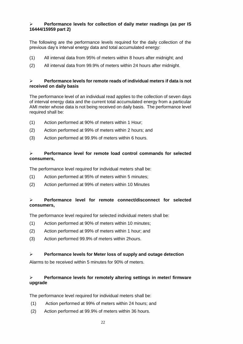
Performance levels for collection of daily meter readings (as per IS 16444/15959 part 2)
The following are the performance levels required for the daily collection of the previous day’s interval energy data and total accumulated energy: (1) All interval data from 95% of meters within 8 hours after midnight; and
(2) All interval data from 99.9% of meters within 24 hours after midnight.
Performance levels for remote reads of individual meters if data is not received on daily basis The performance level of an individual read applies to the collection of seven days of interval energy data and the current total accumulated energy from a particular AMI meter whose data is not being received on daily basis. The performance level required shall be: (1) Action performed at 90% of meters within 1 Hour;
(2) Action performed at 99% of meters within 2 hours; and
(3) Action performed at 99.9% of meters within 6 hours.
Performance level for remote load control commands for selected consumers, The performance level required for individual meters shall be:
(1) Action performed at 95% of meters within 5 minutes;
(2) Action performed at 99% of meters within 10 Minutes
Performance level for remote connect/disconnect for selected consumers, The performance level required for selected individual meters shall be:
(1) Action performed at 90% of meters within 10 minutes;
(2) Action performed at 99% of meters within 1 hour; and
(3) Action performed 99.9% of meters within 2hours.
Performance levels for Meter loss of supply and outage detection
Alarms to be received within 5 minutes for 90% of meters.
Performance levels for remotely altering settings in meter/ firmware upgrade
The performance level required for individual meters shall be:
(1) Action performed at 99% of meters within 24 hours; and
(2) Action performed at 99.9% of meters within 36 hours.
23
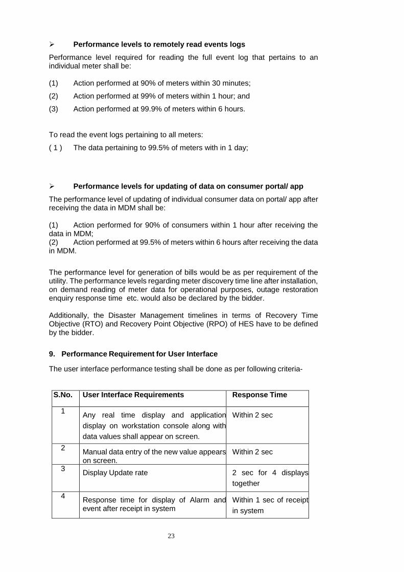
Performance levels to remotely read events logs
Performance level required for reading the full event log that pertains to an individual meter shall be: (1) Action performed at 90% of meters within 30 minutes;
(2) Action performed at 99% of meters within 1 hour; and
(3) Action performed at 99.9% of meters within 6 hours.
To read the event logs pertaining to all meters:
( 1 ) The data pertaining to 99.5% of meters with in 1 day;
Performance levels for updating of data on consumer portal/ app
The performance level of updating of individual consumer data on portal/ app after receiving the data in MDM shall be: (1) Action performed for 90% of consumers within 1 hour after receiving the data in MDM; (2) Action performed at 99.5% of meters within 6 hours after receiving the data in MDM.
The performance level for generation of bills would be as per requirement of the utility. The performance levels regarding meter discovery time line after installation, on demand reading of meter data for operational purposes, outage restoration enquiry response time etc. would also be declared by the bidder. Additionally, the Disaster Management timelines in terms of Recovery Time Objective (RTO) and Recovery Point Objective (RPO) of HES have to be defined by the bidder.
9. Performance Requirement for User Interface The user interface performance testing shall be done as per following criteria-
S.No. User Interface Requirements Response Time
1 Any real time display and application
display on workstation console along with
data values shall appear on screen.
Within 2 sec
2 Manual data entry of the new value appears on screen.
Within 2 sec
3 Display Update rate
2 sec for 4 displays
together
4 Response time for display of Alarm and event after receipt in system
Within 1 sec of receipt
in system
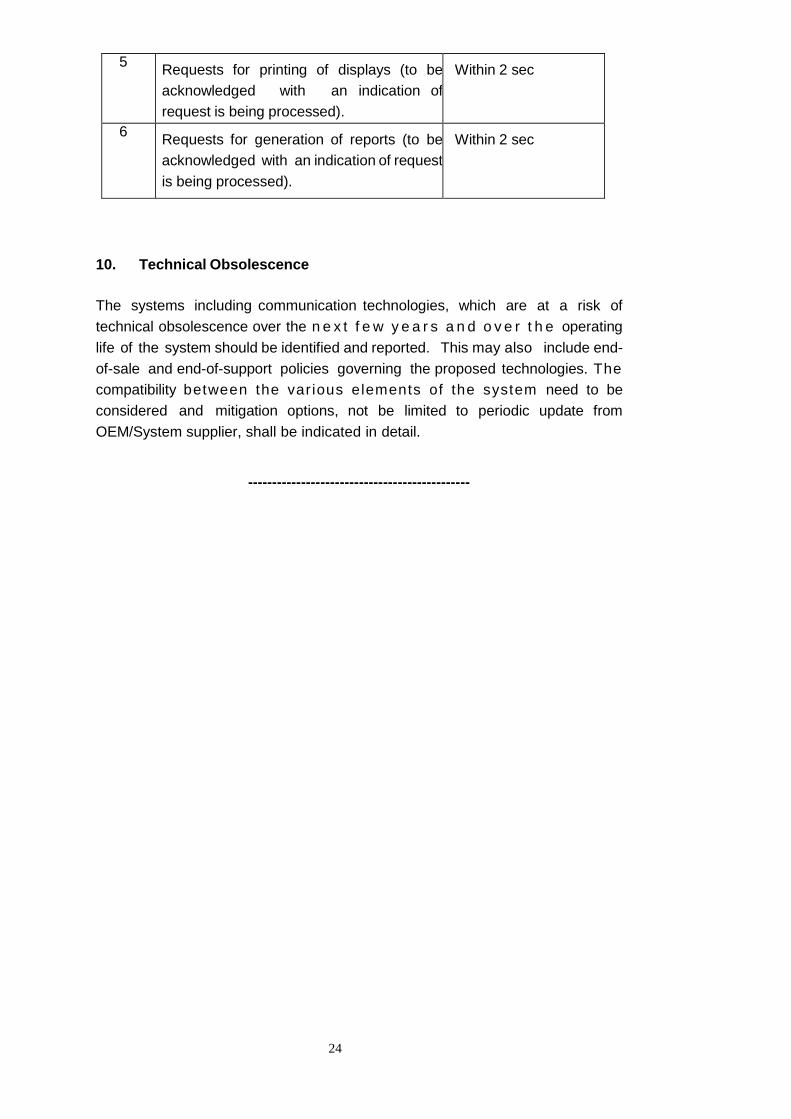
24
5 Requests for printing of displays (to be
acknowledged with an indication of
request is being processed).
Within 2 sec
6 Requests for generation of reports (to be
acknowledged with an indication of request
is being processed).
Within 2 sec
10. Technical Obsolescence The systems including communication technologies, which are at a risk of
technical obsolescence over the n e x t f e w y e a r s a n d o v e r t h e operating
life of the system should be identified and reported. This may also include end-
of-sale and end-of-support policies governing the proposed technologies. The
compatibility between the var ious elements of the system need to be
considered and mitigation options, not be limited to periodic update from
OEM/System supplier, shall be indicated in detail.
----------------------------------------------
25
Technical Specification of
Single phase whole current Smart Meter
26
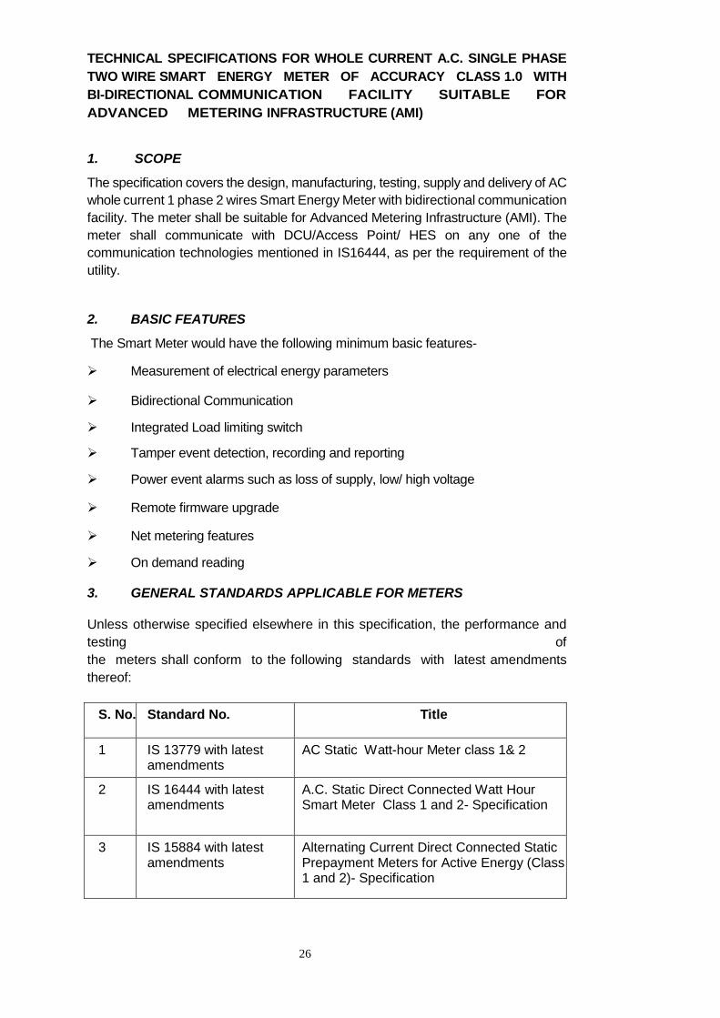
TECHNICAL SPECIFICATIONS FOR WHOLE CURRENT A.C. SINGLE PHASE
TWO WIRE SMART ENERGY METER OF ACCURACY CLASS 1.0 WITH
BI-DIRECTIONAL COMMUNICATION FACILITY SUITABLE FOR
ADVANCED METERING INFRASTRUCTURE (AMI)
1. SCOPE
The specification covers the design, manufacturing, testing, supply and delivery of AC
whole current 1 phase 2 wires Smart Energy Meter with bidirectional communication
facility. The meter shall be suitable for Advanced Metering Infrastructure (AMI). The
meter shall communicate with DCU/Access Point/ HES on any one of the
communication technologies mentioned in IS16444, as per the requirement of the
utility.
2. BASIC FEATURES
The Smart Meter would have the following minimum basic features-
Measurement of electrical energy parameters
Bidirectional Communication
Integrated Load limiting switch
Tamper event detection, recording and reporting
Power event alarms such as loss of supply, low/ high voltage
Remote firmware upgrade
Net metering features
On demand reading
3. GENERAL STANDARDS APPLICABLE FOR METERS
Unless otherwise specified elsewhere in this specification, the performance and
testing of
the meters shall conform to the following standards with latest amendments
thereof:
S. No. Standard No. Title
1 IS 13779 with latest amendments
AC Static Watt-hour Meter class 1& 2
2 IS 16444 with latest amendments
A.C. Static Direct Connected Watt Hour Smart Meter Class 1 and 2- Specification
3 IS 15884 with latest amendments
Alternating Current Direct Connected Static Prepayment Meters for Active Energy (Class 1 and 2)- Specification
27
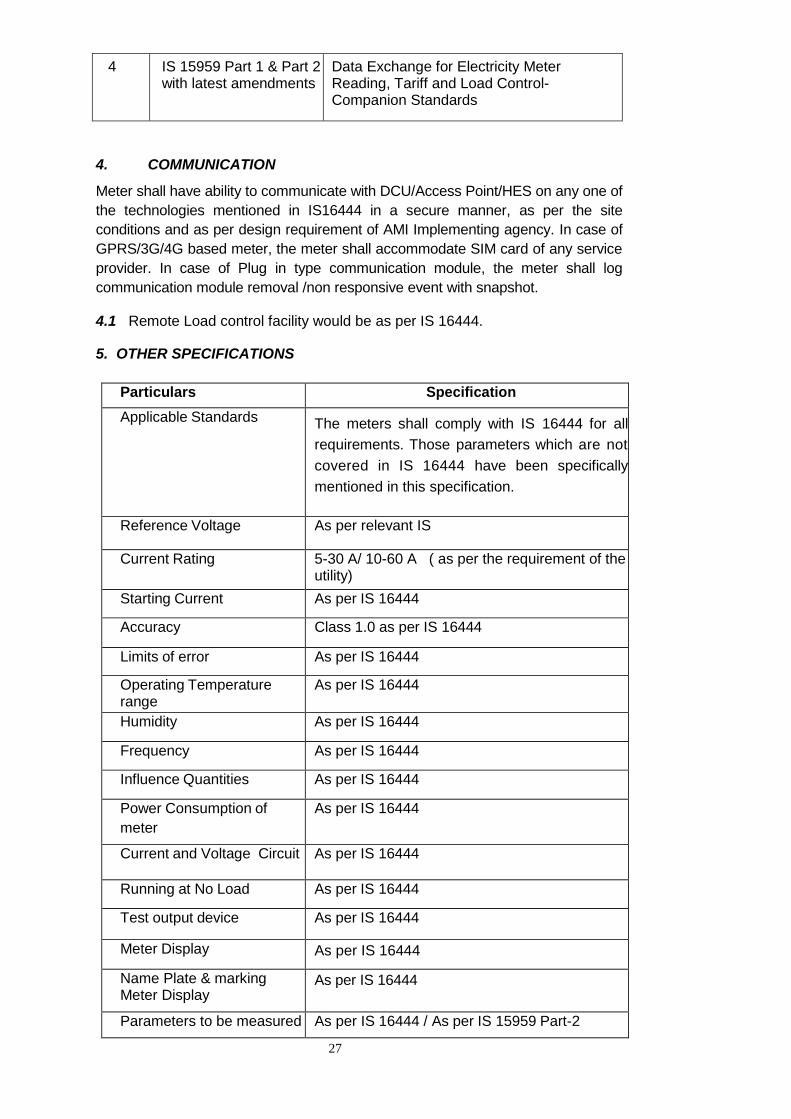
4 IS 15959 Part 1 & Part 2 with latest amendments
Data Exchange for Electricity Meter Reading, Tariff and Load Control-Companion Standards
4. COMMUNICATION
Meter shall have ability to communicate with DCU/Access Point/HES on any one of
the technologies mentioned in IS16444 in a secure manner, as per the site
conditions and as per design requirement of AMI Implementing agency. In case of
GPRS/3G/4G based meter, the meter shall accommodate SIM card of any service
provider. In case of Plug in type communication module, the meter shall log
communication module removal /non responsive event with snapshot.
4.1 Remote Load control facility would be as per IS 16444.
5. OTHER SPECIFICATIONS
Particulars Specification
Applicable Standards The meters shall comply with IS 16444 for all
requirements. Those parameters which are not
covered in IS 16444 have been specifically
mentioned in this specification.
Reference Voltage As per relevant IS
Current Rating 5-30 A/ 10-60 A ( as per the requirement of the utility)
Starting Current As per IS 16444
Accuracy Class 1.0 as per IS 16444
Limits of error As per IS 16444
Operating Temperature range
As per IS 16444
Humidity As per IS 16444
Frequency As per IS 16444
Influence Quantities As per IS 16444
Power Consumption of
meter
As per IS 16444
Current and Voltage Circuit As per IS 16444
Running at No Load As per IS 16444
Test output device As per IS 16444
Meter Display As per IS 16444
Name Plate & marking Meter Display
As per IS 16444
Parameters to be measured As per IS 16444 / As per IS 15959 Part-2
28
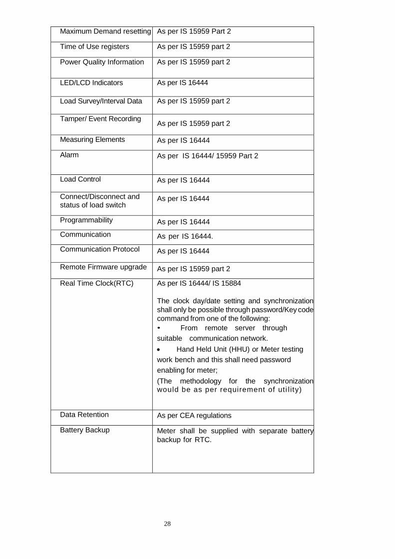
Maximum Demand resetting As per IS 15959 Part 2
Time of Use registers As per IS 15959 part 2
Power Quality Information As per IS 15959 part 2
LED/LCD Indicators As per IS 16444
Load Survey/Interval Data As per IS 15959 part 2
Tamper/ Event Recording As per IS 15959 part 2
Measuring Elements As per IS 16444
Alarm As per IS 16444/ 15959 Part 2
Load Control As per IS 16444
Connect/Disconnect and status of load switch
As per IS 16444
Programmability As per IS 16444
Communication As per IS 16444.
Communication Protocol As per IS 16444
Remote Firmware upgrade As per IS 15959 part 2
Real Time Clock(RTC) As per IS 16444/ IS 15884
The clock day/date setting and synchronization
shall only be possible through password/Key code
command from one of the following:
• From remote server through
suitable communication network.
Hand Held Unit (HHU) or Meter testing
work bench and this shall need password
enabling for meter;
(The methodology for the synchronization would be as per requirement of uti l ity)
Data Retention As per CEA regulations
Battery Backup Meter shall be supplied with separate battery
backup for RTC.
29
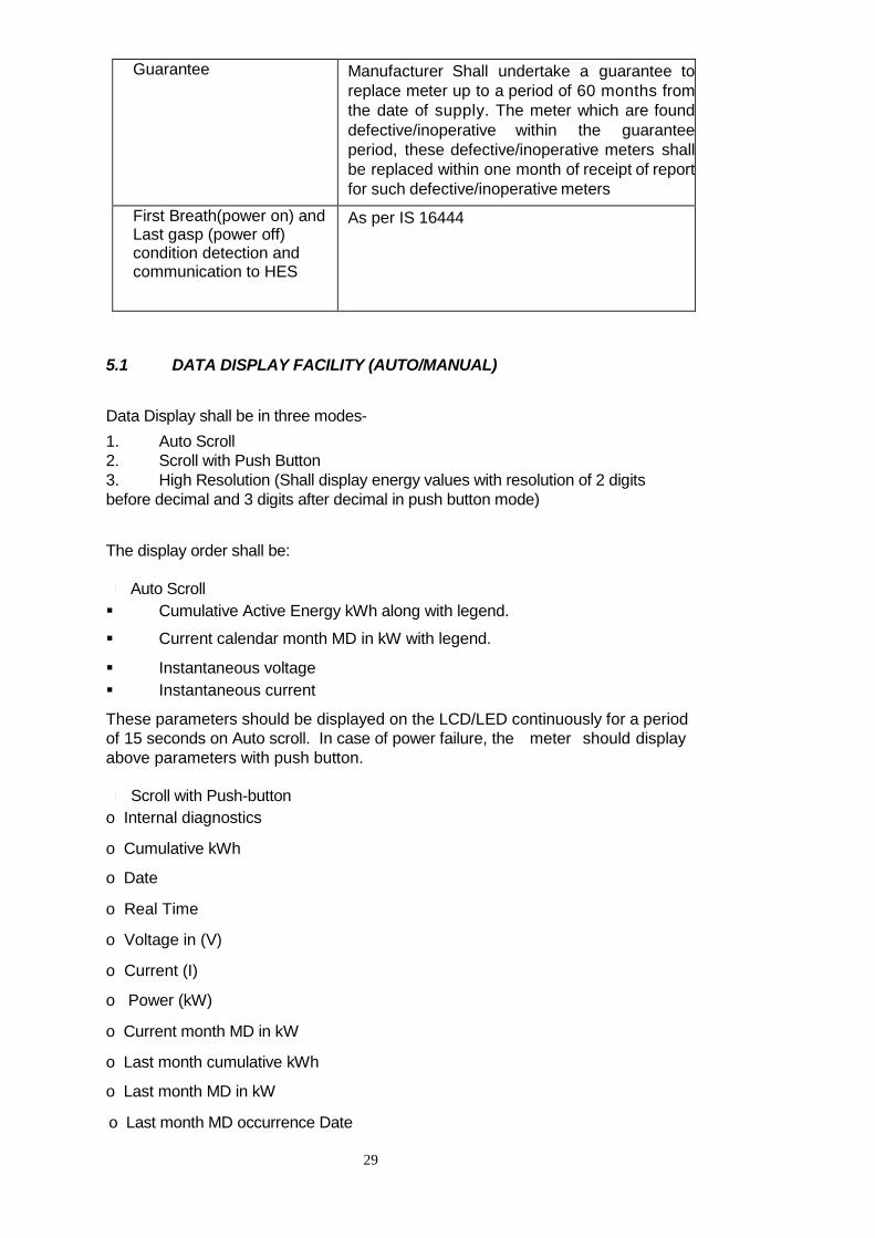
Guarantee Manufacturer Shall undertake a guarantee to
replace meter up to a period of 60 months from
the date of supply. The meter which are found
defective/inoperative within the guarantee
period, these defective/inoperative meters shall
be replaced within one month of receipt of report
for such defective/inoperative meters
First Breath(power on) and Last gasp (power off) condition detection and communication to HES
As per IS 16444
5.1 DATA DISPLAY FACILITY (AUTO/MANUAL)
Data Display shall be in three modes-
1. Auto Scroll
2. Scroll with Push Button
3. High Resolution (Shall display energy values with resolution of 2 digits
before decimal and 3 digits after decimal in push button mode)
The display order shall be:
Auto Scroll
Cumulative Active Energy kWh along with legend.
Current calendar month MD in kW with legend.
Instantaneous voltage
Instantaneous current
These parameters should be displayed on the LCD/LED continuously for a period
of 15 seconds on Auto scroll. In case of power failure, the meter should display
above parameters with push button.
Scroll with Push-button
o Internal diagnostics
o Cumulative kWh
o Date
o Real Time
o Voltage in (V)
o Current (I)
o Power (kW)
o Current month MD in kW
o Last month cumulative kWh
o Last month MD in kW
o Last month MD occurrence Date
30
o Last month MD occurrence Time
o Meter Serial Number
The meter’s display should return to default display mode (continues auto scroll) if
push button is not operated for more than 10 seconds. (The order of display may
be revised as per requirement of the utility)
6. ANTI TAMPER FEATURES
The meter shall continue recording energy under any tamper condition and
would log the event and send alarm at Head End System after detection of the
defined theft features as per IS 15959 Part 2.
(Optional test as per requirement of utility: The Meter shall be immune under external magnetic influences as per CBIP 325. Meter shall be tested for high voltage discharge (Spark) up to 35 KV as per CBIP 325. ) 7. TESTS 7.1 Type Tests & Test Certificates
Smart meter shall be type tested for all the type tests as per IS: 16444 (latest
version) in a third party independent lab. The number of sampling for testing of
meters and criteria for conformity would be as per IS 16444. Necessary copies of test certificates shall be submitted as per agreement with the
utility.
7.2 Routine & Acceptance Tests
The Factory Acceptance and Routine tests shall be carried out as per IS 16444.
Apart from above test, meter shall be also be tested for all functional requirement
through communication as part of acceptance test
8. GENERAL & CONSTRUCTIONAL REQUIREMENTS
8.1 Meter Shall be BIS marked as per IS 16444.
8.2 General & construction requirement shall be as per IS 16444/IS 13779
8.3 In Home Display (IHD) shall be optional and the specifications of the same
would be as per agreement between the bidder and the utility.
9. METER BASE & COVER- Meter base & cover shall be as per IS 16444/ IS 13779. The meter Base & cover shall be break to open design. The material for meter base and cover shall be made of high grade polycarbonate.
10. TERMINAL BLOCK & COVER - As per IS 16444/IS 13779
31
11. DESIGN Voltage circuit, sealing arrangement, terminal block, terminal cover and nameplate
etc. shall be in accordance with IS-16444 (latest version).
The meter shall be compact and reliable in design, easy to transport and immune
to vibration and shock involved in transportation and handling.
12. CIRCUITRY - as per IS 16444
The supplier should submit the details of source/agencies from whom purchase
of various components of meters used by them to the utility/purchaser.
13. NAME PLATE AND MARKING
The meter should bear a name plate clearly visible, effectively secured against
removal and indelibly/distinctly marked in accordance with relevant IS. In
addition, in the middle of the name plate the words “Name of the Utility”, purchase
order no. & year/month of manufacturing shall either be punched or marked
indelibly. The rating plate information shall be as per relevant IS.
14. CONNECTION DIAGRAM: As per IS 16444 15. FIXING ARRANGEMENTS: The meter shall be mounted type. The Meter should have three fixing holes, one
at top and two at the bottom. The Top hole should be such that the holding screw
is not accessible to the consumer after fixing the meters. The lower screws
should be provided under sealable terminal cover. The requisite fixing screws
shall be supplied with each meter.
16. SEALING ARRANGEMENT: Arrangements shall be provided for proper sealing of the meter cover so that access to the working parts shall not be possible without breaking the seal. The sea l ing a r rangement and number o f sea ls sha l l be as pe r re levan t IS / requ i rement o f u t i l i t y .
17. METER BOX: The Meter Box would be provided as per requirement of the utility/ purchaser. 18. PACKING The meters shall be suitably packed for vertical/horizontal support to withstand
handling during transportation. The meter shall be packed appropriately to
ensure safe transportation, handling, identification and storage. All packing
materials shall be as per environment law in force. The primary packing shall
ensure protection against humidity, dust, grease and safeguard the meter’s
performance until its installation. The secondary packing shall provide protection
during transportation. The packing case shall indicate “Fragile in nature” and

32
direction of placement of box. Each packing shall indicate marking details like
Manufacturer’s name, S.No. of meters, quantity etc. 19. TRANSPORTATION
The meter shall be compact in design. The meter block unit shall be capable of
withstanding stresses likely to occur in actual service and rough handling during
transportation. The meter shall be convenient to transport and immune to shock
and vibration during transportation and handling.
The meter should not be exposed to undue shock and mishandling during
transportation. The stacking of box inside transport media should be such as to
avoid their free movement. The packing should also be protected from rain and
dust by transport media. The Bidder shall be responsible for any damage during
transit due to inadequate or improper packing.
20. TESTING AND MANUFACTURING FACILITIES AT MANUFACTURER’S PLACE The manufacturer shall have NABL accredited laboratory to ensure accurate testing calibration as per IS 13779 for acceptance test. 21. INSPECTION All meters shall be duly tested and sealed by the firm at their premises
prior to inspection. Manufacturer seal may be provided on one side of meter. For
the other side, the seal with engrave as Utility name may be sent in a pack for
provision by utility after completion of test by the utility & after receipt of the meter. The ut i l i ty/ purchaser may inspect the meter randomly as per
sampling plan for acceptance test as per IS 16444. The meters shall be tested
for all functional requirements as part of acceptance test as per IS 16444. After
testing, these sample meters shall be additionally sealed and would be kept in
safe lock for verification if needed.
****************************************************
33
Technical Specification of
Three phase whole current Smart Meter
34
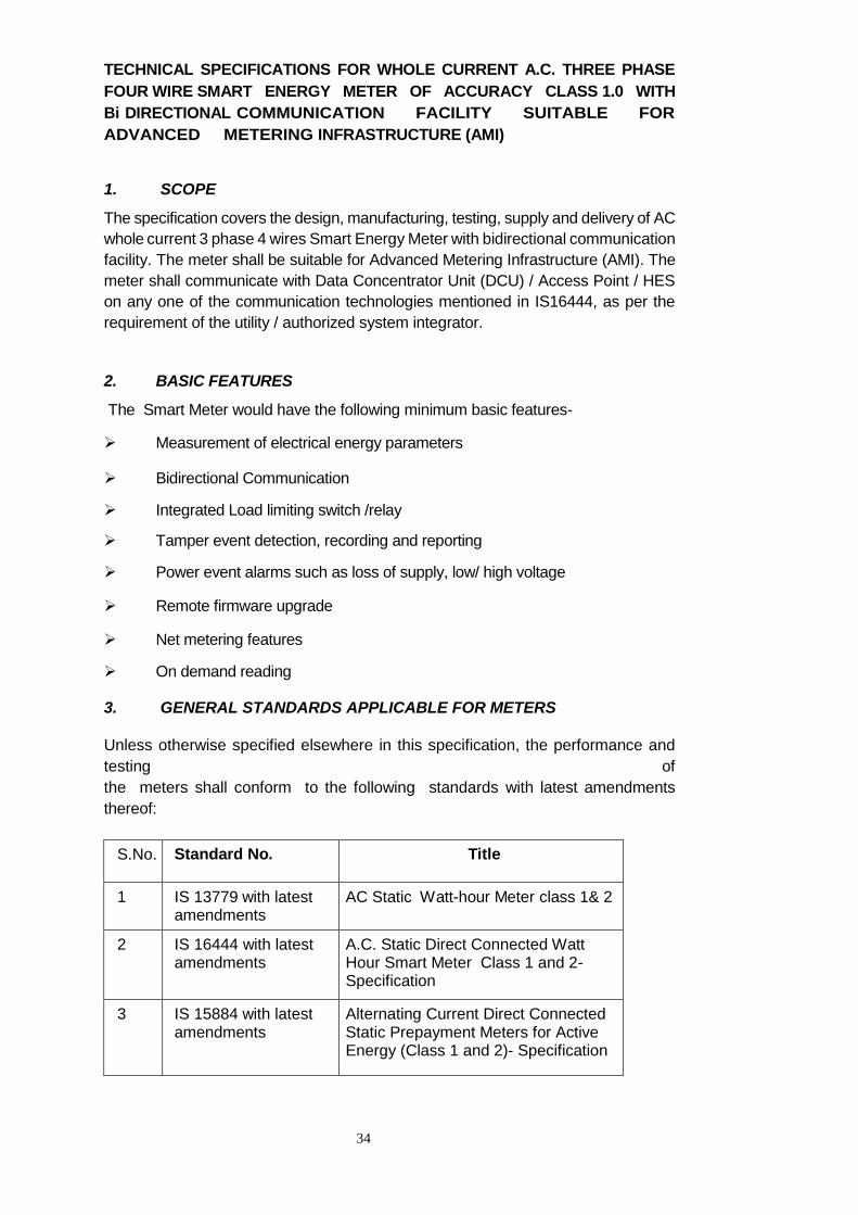
TECHNICAL SPECIFICATIONS FOR WHOLE CURRENT A.C. THREE PHASE
FOUR WIRE SMART ENERGY METER OF ACCURACY CLASS 1.0 WITH
Bi DIRECTIONAL COMMUNICATION FACILITY SUITABLE FOR
ADVANCED METERING INFRASTRUCTURE (AMI)
1. SCOPE
The specification covers the design, manufacturing, testing, supply and delivery of AC
whole current 3 phase 4 wires Smart Energy Meter with bidirectional communication
facility. The meter shall be suitable for Advanced Metering Infrastructure (AMI). The
meter shall communicate with Data Concentrator Unit (DCU) / Access Point / HES
on any one of the communication technologies mentioned in IS16444, as per the
requirement of the utility / authorized system integrator.
2. BASIC FEATURES
The Smart Meter would have the following minimum basic features-
Measurement of electrical energy parameters
Bidirectional Communication
Integrated Load limiting switch /relay
Tamper event detection, recording and reporting
Power event alarms such as loss of supply, low/ high voltage
Remote firmware upgrade
Net metering features
On demand reading
3. GENERAL STANDARDS APPLICABLE FOR METERS
Unless otherwise specified elsewhere in this specification, the performance and
testing of
the meters shall conform to the following standards with latest amendments
thereof:
S.No. Standard No. Title
1 IS 13779 with latest amendments
AC Static Watt-hour Meter class 1& 2
2 IS 16444 with latest amendments
A.C. Static Direct Connected Watt Hour Smart Meter Class 1 and 2- Specification
3 IS 15884 with latest amendments
Alternating Current Direct Connected Static Prepayment Meters for Active Energy (Class 1 and 2)- Specification
35
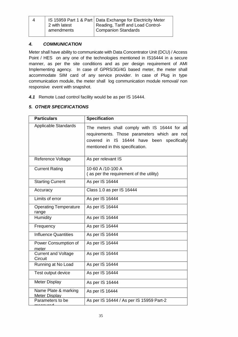
4. COMMUNICATION
Meter shall have ability to communicate with Data Concentrator Unit (DCU) / Access
Point / HES on any one of the technologies mentioned in IS16444 in a secure
manner, as per the site conditions and as per design requirement of AMI
Implementing agency. In case of GPRS/3G/4G based meter, the meter shall
accommodate SIM card of any service provider. In case of Plug in type
communication module, the meter shall log communication module removal/ non
responsive event with snapshot.
4.1 Remote Load control facility would be as per IS 16444.
5. OTHER SPECIFICATIONS
Particulars Specification
Applicable Standards The meters shall comply with IS 16444 for all
requirements. Those parameters which are not
covered in IS 16444 have been specifically
mentioned in this specification.
Reference Voltage As per relevant IS
Current Rating 10-60 A /10-100 A ( as per the requirement of the utility)
Starting Current As per IS 16444
Accuracy Class 1.0 as per IS 16444
Limits of error As per IS 16444
Operating Temperature range
As per IS 16444
Humidity As per IS 16444
Frequency As per IS 16444
Influence Quantities As per IS 16444
Power Consumption of
meter
As per IS 16444
Current and Voltage Circuit
As per IS 16444
Running at No Load As per IS 16444
Test output device As per IS 16444
Meter Display As per IS 16444
Name Plate & marking Meter Display
As per IS 16444
Parameters to be measured
As per IS 16444 / As per IS 15959 Part-2
4 IS 15959 Part 1 & Part 2 with latest amendments
Data Exchange for Electricity Meter Reading, Tariff and Load Control-Companion Standards
36
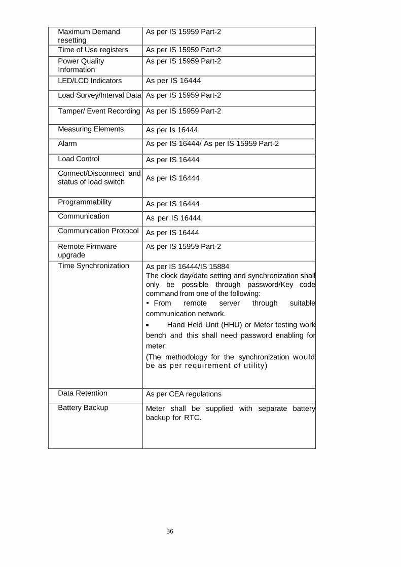
Maximum Demand resetting
As per IS 15959 Part-2
Time of Use registers As per IS 15959 Part-2
Power Quality Information
As per IS 15959 Part-2
LED/LCD Indicators As per IS 16444
Load Survey/Interval Data As per IS 15959 Part-2
Tamper/ Event Recording As per IS 15959 Part-2
Measuring Elements As per Is 16444
Alarm As per IS 16444/ As per IS 15959 Part-2
Load Control As per IS 16444
Connect/Disconnect and status of load switch
As per IS 16444
Programmability As per IS 16444
Communication As per IS 16444.
Communication Protocol As per IS 16444
Remote Firmware upgrade
As per IS 15959 Part-2
Time Synchronization As per IS 16444/IS 15884
The clock day/date setting and synchronization shall
only be possible through password/Key code
command from one of the following:
• From remote server through suitable
communication network.
Hand Held Unit (HHU) or Meter testing work
bench and this shall need password enabling for
meter;
(The methodology for the synchronization would be as per requirement of ut i lity)
Data Retention As per CEA regulations
Battery Backup Meter shall be supplied with separate battery
backup for RTC.
37
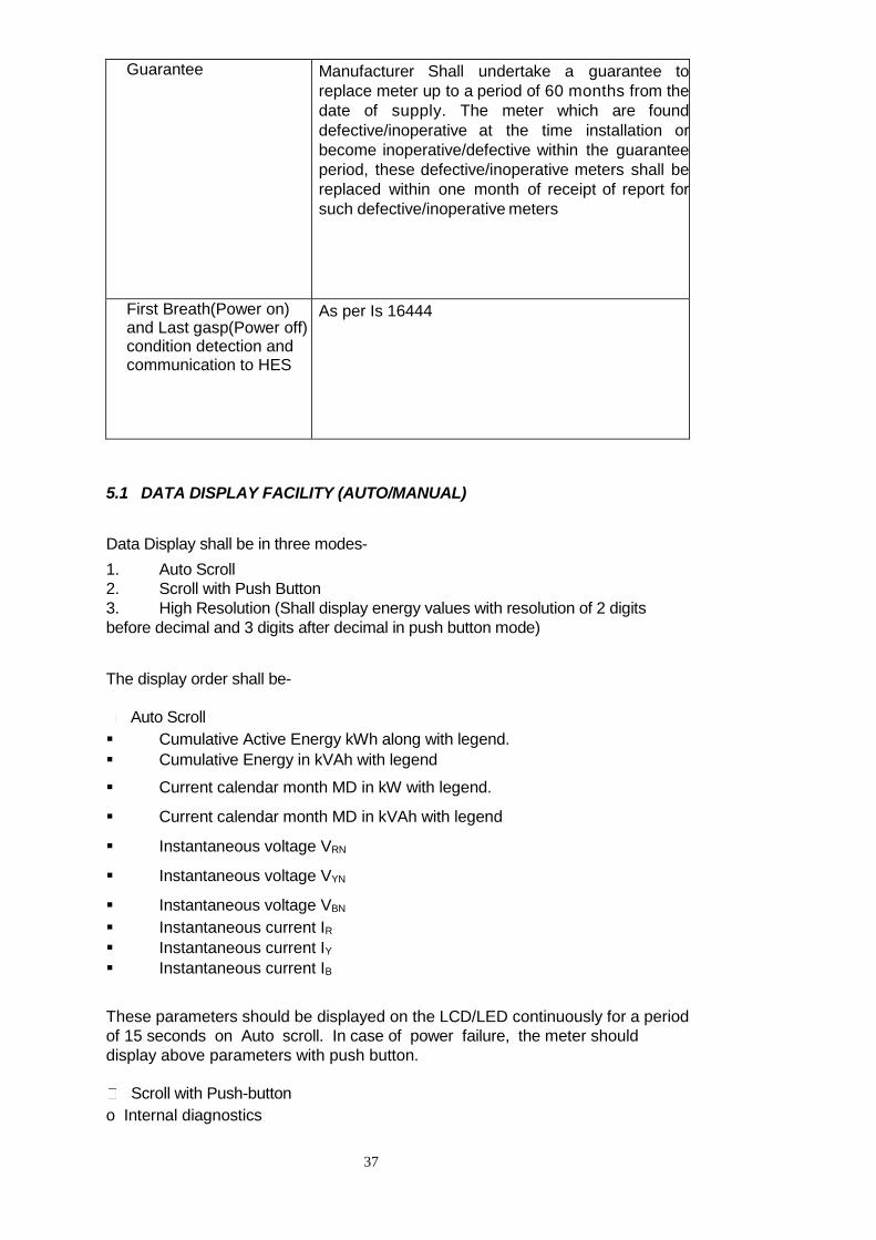
Guarantee Manufacturer Shall undertake a guarantee to
replace meter up to a period of 60 months from the
date of supply. The meter which are found
defective/inoperative at the time installation or
become inoperative/defective within the guarantee
period, these defective/inoperative meters shall be
replaced within one month of receipt of report for
such defective/inoperative meters
First Breath(Power on) and Last gasp(Power off) condition detection and communication to HES
As per Is 16444
5.1 DATA DISPLAY FACILITY (AUTO/MANUAL)
Data Display shall be in three modes-
1. Auto Scroll
2. Scroll with Push Button
3. High Resolution (Shall display energy values with resolution of 2 digits
before decimal and 3 digits after decimal in push button mode)
The display order shall be-
Auto Scroll
Cumulative Active Energy kWh along with legend.
Cumulative Energy in kVAh with legend
Current calendar month MD in kW with legend.
Current calendar month MD in kVAh with legend
Instantaneous voltage VRN
Instantaneous voltage VYN
Instantaneous voltage VBN
Instantaneous current IR
Instantaneous current IY
Instantaneous current IB
These parameters should be displayed on the LCD/LED continuously for a period
of 15 seconds on Auto scroll. In case of power failure, the meter should
display above parameters with push button.
Scroll with Push-button
o Internal diagnostics
38
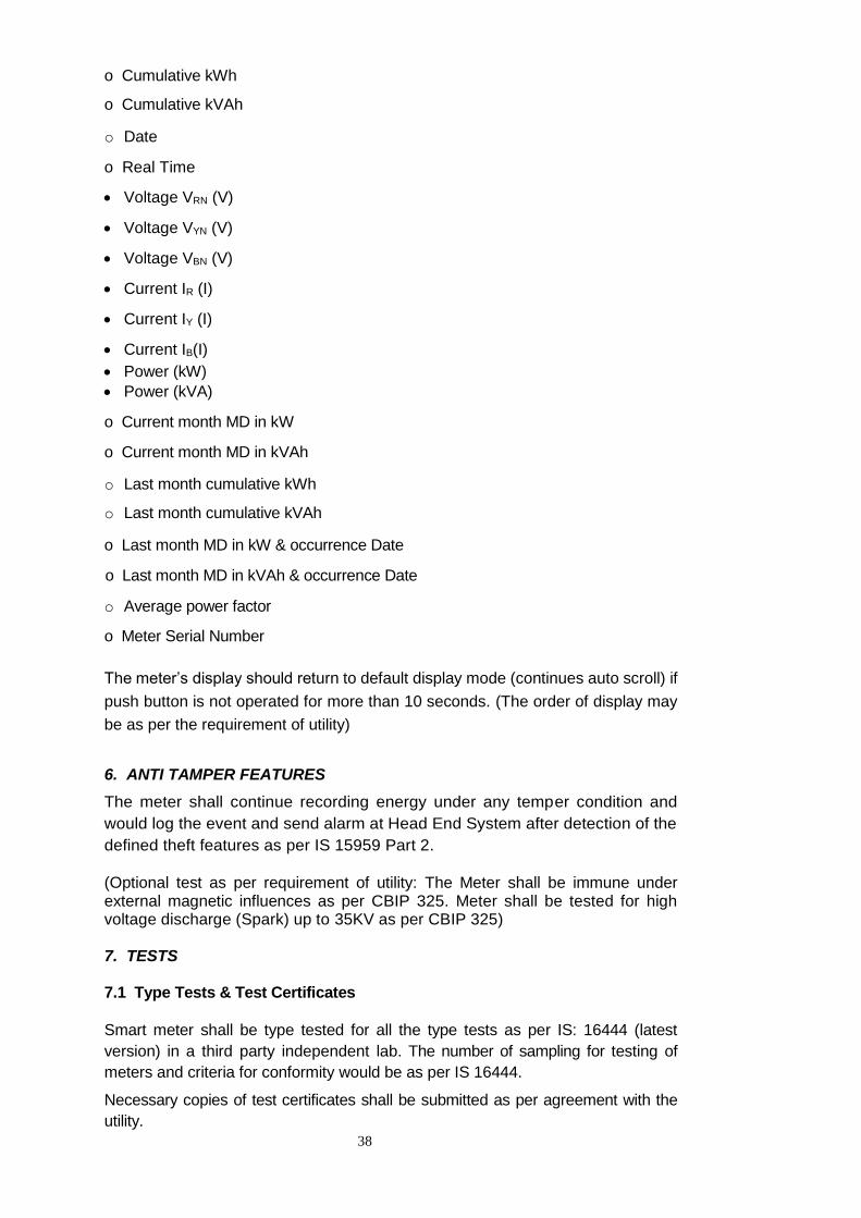
o Cumulative kWh
o Cumulative kVAh
o Date
o Real Time
Voltage VRN (V)
Voltage VYN (V)
Voltage VBN (V)
Current IR (I)
Current IY (I)
Current IB(I)
Power (kW)
Power (kVA)
o Current month MD in kW
o Current month MD in kVAh
o Last month cumulative kWh
o Last month cumulative kVAh
o Last month MD in kW & occurrence Date
o Last month MD in kVAh & occurrence Date
o Average power factor
o Meter Serial Number
The meter’s display should return to default display mode (continues auto scroll) if
push button is not operated for more than 10 seconds. (The order of display may
be as per the requirement of utility)
6. ANTI TAMPER FEATURES
The meter shall continue recording energy under any temper condition and
would log the event and send alarm at Head End System after detection of the
defined theft features as per IS 15959 Part 2.
(Optional test as per requirement of utility: The Meter shall be immune under external magnetic influences as per CBIP 325. Meter shall be tested for high voltage discharge (Spark) up to 35KV as per CBIP 325) 7. TESTS 7.1 Type Tests & Test Certificates
Smart meter shall be type tested for all the type tests as per IS: 16444 (latest
version) in a third party independent lab. The number of sampling for testing of
meters and criteria for conformity would be as per IS 16444. Necessary copies of test certificates shall be submitted as per agreement with the
utility.
39
7.2 Routine & Acceptance Tests
The Factory Acceptance and Routine tests shall be carried out as per IS 16444.
Apart from above test, meter shall also be tested for all functional requirement
through communication as part of acceptance test.
8. GENERAL & CONSTRUCTIONAL REQUIREMENTS
8.1 Meter Shall be BIS marked as per IS 16444.
8.2 General & construction requirement shall be as per IS 16444/IS 13779.
8.3 In Home Display(IHD) shall be optional and the specifications of the same would
be as per agreement between the bidder and the utility.
9. METER BASE & COVER-
The meter Base & cover shall be as per IS 16444/IS 13779. The meter base and
cover break to open design. The material for meter base and cover shall be made
of high grade polycarbonate.
10. TERMINAL BLOCK & COVER - As per IS 16444/IS 13779
11. DESIGN Voltage circuit, sealing arrangement, terminal block, terminal cover and nameplate
etc. shall be in accordance with IS-16444 (latest version).
The meter shall be compact and reliable in design, easy to transport and immune
to vibration and shock involved in transportation and handling.
12. CIRCUITRY – As per IS 16444
The supplier should submit the details of source/agencies from whom purchase
of various components of meters used by them to the utility/purchaser.
13. NAME PLATE AND MARKING
The meter should bear a name plate clearly visible, effectively secured against
removal and indelibly/distinctly marked in accordance with relevant IS. In
addition, in the middle of the name plate the words “Name of the Utility”, purchase
order no. & year/month of manufacturing shall either be punched or marked
indelibly. The rating plate information shall be as per relevant IS.
14. CONNECTION DIAGRAM: As per IS 16444
40
15. FIXING ARRANGEMENTS: The meter shall be mounted type. The Meter should have three fixing holes, one
at top and two at the bottom. The Top hole should be such that the holding screw
is not accessible to the consumer after fixing the meters. The lower screws
should be provided under sealable terminal cover. The requisite fixing screws
shall be supplied with each meter.
16. SEALING ARRANGEMENT: Arrangements shall be provided for proper sealing of the meter cover so that
access to the working parts shall not be possible without breaking the seal. The
sealing arrangement and number of seals shall be as per relevant IS/ requirement
of utility.
17. METER BOX: The Meter Box would be provided as per requirement of the utility. 18. PACKING The meters shall be suitably packed for vertical/horizontal support to withstand
handling during transportation.
The meter shall be packed appropriately to ensure safe transportation,
handling, identification and storage.
All packing materials shall be as per environment law in force. The primary
packing shall ensure protection against humidity, dust, grease and safeguard
the meter’s performance until its installation.
The secondary packing shall provide protection during transportation.
The packing case shall indicate “Fragile in nature” and direction of placement
of box.
Each packing shall indicate marking details like Manufacturer’s name, S.No. of
meters, quantity etc.
19. TRANSPORTATION
The meter shall be compact in design. The meter block unit shall be capable
of withstanding stresses likely to occur in actual service and rough handling
during transportation.
The meter shall be convenient to transport and immune to shock and vibration
during transportation and handling.
The meter should not be exposed to undue shock and mishandling during
transportation.
The stacking of box inside transport media should be such as to avoid their
free movement.
The packing should also be protected from rain and dust by transport media.
41
The Bidder shall be responsible for any damage during transit due to
inadequate or improper packing.
20. TESTING AND MANUFACTURING FACILITIES AT MANUFACTURER’S PLACE The manufacturer shall have NABL accredited laboratory to ensure accurate testing calibration as per IS 13779 for acceptance test. 21. INSPECTION All meters shall be duly tested and sealed by the firm at their premises
prior to inspection. Manufacturer seal may be provided on one side of meter. For
the other side, the seal with engrave as Utility name may be sent in a pack for
provision by utility after completion of test by the utility & after receipt of the meter. The utility/ purchaser may inspect the meter randomly as per sampling
plan for acceptance test as per IS 16444. The meters shall be tested for all
functional requirements as part of acceptance test as per IS 16444. After testing,
these sample meters shall be additionally sealed and kept in a safe lock for
verification, if needed.
****************************************************