FUNCTIONAL DESCRIPTION UMC22 ACT02 - ABB Group · Functional Unit UMC22_Act02 Functional...
39
We reserve all rights in this document and in the information contained therein. Reproduction, use or disclosure to third parties without express authority is strictly forbidden. ABB Prep. / 10-11-30 Function Description No. of p. Appr. AT/PA/RS/ Bengt Persson Approved 39 Resp. dept. UMC22_Act02 Functional Description Doc. no. Lang. Rev. ind. Page ABB AB 3AST 001 599D004 en C 1 Functional Descr UMC22_Act02RevC.doc; TECHN_DOC_STAND_P.DOT; 2010-11-29 20:44 FUNCTIONAL DESCRIPTION UMC22_ACT02 Position Motorized Valve
Transcript of FUNCTIONAL DESCRIPTION UMC22 ACT02 - ABB Group · Functional Unit UMC22_Act02 Functional...

We reserve all rights in this document and in the information contained therein. Reproduction, use or disclosure to third parties without express authority is strictly forbidden. ABB
Prep. / 10-11-30 Function Description No. of p.
Appr. AT/PA/RS/ Bengt Persson Approved 39
Resp. dept.
UMC22_Act02 Functional Description
Doc. no. Lang. Rev. ind. Page
ABB AB 3AST 001 599D004 en C 1
Functional Descr UMC22_Act02RevC.doc; TECHN_DOC_STAND_P.DOT; 2010-11-29 20:44
FUNCTIONAL DESCRIPTION
UMC22_ACT02 Position Motorized Valve

Functional Unit UMC22_Act02 Functional Description
Doc. no. Lang. Rev. ind. Page
ABB AB 3AST 001 599D004 en C 2
Contents
1 General ..................................................................................................................... 4
2 Configuration ........................................................................................................... 4
3 Function Block UMC22_Act02................................................................................. 5
4 UMC22_ACT Datatypes ........................................................................................... 8
4.1 UMC22_ACT_InPar...................................................................................... 8 4.2 UMC22_ACT_OutPar................................................................................... 9 4.3 UMC22_ACT_Opr ...................................................................................... 10
5 Function.................................................................................................................. 11
5.1 Basic properties.......................................................................................... 11 5.2 Control Modes............................................................................................ 11 5.3 Ready for Start ........................................................................................... 11 5.4 Start-up ...................................................................................................... 12 5.5 lnterlocks.................................................................................................... 12 5.6 Control Modes............................................................................................ 12
5.6.1 Control mode JOG........................................................................ 12 5.6.2 Control mode LOCAL.................................................................... 13 5.6.3 Control mode AUTO ..................................................................... 14 5.6.4 Control mode MANUAL ................................................................ 14 5.6.5 Control mode EXTERNAL 1.......................................................... 14 5.6.6 Control mode EXTERNAL 2.......................................................... 14 5.6.7 Control mode EXTERNAL 3.......................................................... 15 5.6.8 Control mode DISABLED.............................................................. 15 5.6.9 Control mode Panel Mode ............................................................ 15 5.6.10 Operator Order and Order Blocking .............................................. 15
5.7 Open, Close and Stop ................................................................................ 15 5.7.1 Open and Close on Torque........................................................... 16 5.7.2 Open, Close and Stop Order at Different Control Modes .............. 17 5.7.3 Start Order Selection .................................................................... 18
5.8 Fault Evaluation in the Control Circuit......................................................... 19 5.9 Supervision of Motor Current...................................................................... 19 5.10 Alarm Handling........................................................................................... 19 5.11 Event handling............................................................................................ 19
5.11.1 UMC22_ACT02 Interaction Window ............................................. 20 5.11.2 General Parameters ..................................................................... 20 5.11.3 Order Block................................................................................... 21 5.11.4 Alarm and Event Block.................................................................. 21 5.11.5 Interlock Settings .......................................................................... 22 5.11.6 Current settings ............................................................................ 23 5.11.7 Actuator Alarm Settings ................................................................ 24 5.11.8 Texts............................................................................................. 24 5.11.9 Limits & Control ............................................................................ 24
6 Operator Functions................................................................................................ 26
6.1 Presentation ............................................................................................... 26 6.1.1 Display Elements.......................................................................... 26 6.1.2 Time-logged Properties................................................................. 30
6.2 Faceplate(Dialog) ....................................................................................... 31 6.3 Alarm and Event Handling.......................................................................... 33
6.3.1 General......................................................................................... 33 6.3.2 Alarm and Event Message............................................................ 34 6.3.3 Diagnostic events ......................................................................... 35

Functional Unit UMC22_Act02 Functional Description
Doc. no. Lang. Rev. ind. Page
ABB AB 3AST 001 599D004 en C 3
6.4 Faceplate tabs............................................................................................ 36 6.4.1 Alarm and Event Blocking............................................................. 36 6.4.2 Limits ............................................................................................ 37 6.4.3 Info Text ....................................................................................... 38

Functional Unit UMC22_Act02 Functional Description
Doc. no. Lang. Rev. ind. Page
ABB AB 3AST 001 599D004 en C 4
1 General
UMC22_Act02 is a functional unit designed for the control of position- motorized valves in different processes.
The functional unit is standardized to a high degree to simplify the work of designing presentation, dialog and control logic. UMC22_ Act02 normally performs its control function without help from other elements.
UMC22_ Act02 is used in the control of motorized valves from various locations such as:
OperateIT Operator Stations
Control desks
Switch Gear
Local control stations
The valves can also be controlled from a master control function e.g. Group Start or Other higher level control functions.
2 Configuration
UMC22_ Act02 comprises a function block type for control and logic functions in ControlIT, a faceplate and an object display in OperateIT for operator functions and control parameters.
MOTOR CONTROL CORE- start/stop logic- interlockings- current calculation
I/O INTERFACE
HSI INTERFACE
VDU Op. Panel Local
Comm. InterfaceN/AP
ARAMETERS
DIAGN.
- alarms
(fault,
warning)
- events
- loggers
HSI
PROCESS OBJECT
Figure 2-1. The Structure of the Functional Unit

Functional Unit UMC22_Act02 Functional Description
Doc. no. Lang. Rev. ind. Page
ABB AB 3AST 001 599D004 en C 5
3 Function Block UMC22_Act02
FUNCTION OF INPUT TERMINALS UMC22_Act02 FUNCTION OF OUTPUT TERMINALS
Object name Name
Object description Description
Enable object Enable
Connection to MCC …………….MCC……………..
UMC22 unit status UMCUnitStatus NoInt No Interlocks
Profibus status UnitStatus NoICInt No Safety Interlocks (IC)
Actuator type ActuatorType NoIBInt No Process Interlocks (IB)
Enable control circuit alarm ME NoIAInt No Sequence Interlocks (IA)
Control voltage M1 Trip Trip
Overload M2 Blk Standby
Motor breaker M3 RFS Ready for start
Emergency stop M4 IPOS Intermediate position
Short Circuit M5 LSOpn Limit Switch Open
Safety Interlock 1 IC1 LSCls Limit Switch Close
Safety Interlock 2 IC2 TorqOpn Torque Limit Switch Open
Safety Interlocks ICs TorqCls Torque Limit Switch Close
Process Interlock 1 IB1 OPN Open order
Process Interlock 2 IB2 OPNL Limit switch open is reached
Process Interlock 3 IB3 CLS Close order
Process Interlock 4 IB4 CLSL Limit switch close is reached
Process Interlocks IBs SAck Start order acknowledgement
Sequence Interlock 1 IA1 Ack1 Main contactor acknowledge open
Sequence Interlock 2 IA2 Ack2 Main contactor acknowledge close
Sequence Interlocks IAs Run Running
Maximum travelling Time T1 TestMode Test mode
Supervision Time T2 PanelMode Panel mode
Reverse lock-out time TRevLockOut JogInd Jog mode
External reference setpoint in E1 mode Ext1Ref NoJogInt No Jog Interlocks
External reference setpoint in E2 mode Ext2Ref LocalInd Local mode
Open order in E3 mode E3Opn ManInd Man mode
Close order in E3 mode E3Cls AutoInd Auto mode
Stop order in external mode Stop E1Ind E1 mode
Actuator position ActPos E2Ind E2 mode
Position transmitter error PosErr E3Ind E3 mode
Order mode to Jog JogEnbl AutoSP Auto setpoint
Open order in Jog mode JogOpn WSP Working setpoint
Close order in Jog mode JogCls Deviation Deviation
Jog start hold function JogFunc PosError Position Error
Order mode to Local LEnbl NormCurr Normal current (%)
Open order in Local mode LOpn Curr Actual current (%)
Close order in Local mode LCls Current Actual current (in unit)
Local Stop order LStop OutPar Out Parameter
Order mode to Man SeqMan Opr Operator order
Order mode to Auto SeqAuto
Order mode to E1 SeqE1
Order mode to E2 SeqE2
Order mode to E3 SeqE3
Set Test Mode from MCC SetTest
Auto setpoint tracking Ext1 or Ext2 TrackA
Max Auto setpoint change rate when tranfer from E1 or E2 (unit/s)
SpeedA
Deviation between setpoint and position transmitter
DevDB
Pulse frequency factor in the CON_PU1 PF
Pulse length factor in the CON_PU1 K
DeadBand in the CON_PU1 DeadB
Block alarm AlcBlk
Acknowledge alarm AlarmAck
Actuator position alarm configuration ActPosAlarms

Functional Unit UMC22_Act02 Functional Description
Doc. no. Lang. Rev. ind. Page
ABB AB 3AST 001 599D004 en C 6
In Parameter InPar
Event name EventName
Figure 3-1. UMC22_ACT02 Function Block, Complete symbol
Table 3-1 below illustrates the default properties of each terminal of the UMC22_ACT02 function block.
Name Data Type Attributes Direction FD
Port Initial value Description
Name string coldretain in yes 'UMC22_Act02'
Object name
Description string coldretain in yes 'Descr' Object description
Enable bool coldretain in yes true Enable object
MCC UMC22_DP in_out yes Communication with MCC
UMCUnitStatus HwStatus by_ref in yes UMC22 unit status
UnitStatus dint retain in yes Profibus status
ActuatorType dint coldretain in yes 1 Actuator type
ME bool retain in yes true Enable control circuit alarm
M1 bool retain in yes true Control voltage
M2 bool retain in yes true Overload
M3 bool retain in yes true Motor breaker
M4 bool retain in yes true Emergency stop
M5 bool retain in yes true Short Circuit
IC1 bool retain in yes true Safety Interlock 1
IC2 bool retain in yes true Safety Interlock 2
ICs ICConn by_ref in yes Safety Interlocks
IB1 bool retain in yes true Process Interlock 1
IB2 bool retain in yes true Process Interlock 2
IB3 bool retain in yes true Process Interlock 3
IB4 bool retain in yes true Process Interlock 4
IBs IBConn by_ref in yes Process Interlocks
IA1 bool retain in yes true Sequence Interlock 1
IA2 bool retain in yes true Sequence Interlock 2
IAs IAConn by_ref in yes Sequence Interlocks
T1 time coldretain in yes 60s Maximum travelling Time
T2 time coldretain in yes 4s Supervision Time
TRevLockOut time coldretain in yes 2s Reverse lock-out time
Ext1Ref real retain in yes External reference setpoint in E1 mode
Ext2Ref real retain in yes External reference setpoint in E2 mode
E3Opn bool retain in yes Open order in E3 mode
E3Cls bool retain in yes Close order in E3 mode
Stop bool retain in yes Stop order in external mode
ActPos real retain in yes Actuator position
PosErr bool retain in yes Position transmitter error
JogEnbl bool retain in yes Order mode to Jog
JogOpn bool retain in yes Open order in Jog mode
JogCls bool retain in yes Close order in Jog mode
JogFunc bool retain in yes Jog start hold function
LEnbl bool retain in yes Order mode to Local
LOpn bool retain in yes Open order in Local mode
LCls bool retain in yes Close order in Local mode
LStop bool retain in yes true Local Stop order
SeqMan bool retain in yes Order mode to Man
SeqAuto bool retain in yes Order mode to Auto
SeqE1 bool retain in yes Order mode to E1
SeqE2 bool retain in yes Order mode to E2
SeqE3 bool retain in yes Order mode to E3
SetTest dint coldretain in yes -1 Set Test Mode from MCC (0 = DI0, 1 = DI1, 2 = DI2, 3 = DI3, 4 = DI4, 5 = DI5)
TrackA bool coldretain in yes true Auto setpoint tracking Ext1 or Ext2
SpeedA real coldretain in yes 1.0 Max Auto setpoint change rate

Functional Unit UMC22_Act02 Functional Description
Doc. no. Lang. Rev. ind. Page
ABB AB 3AST 001 599D004 en C 7
Name Data Type Attributes Direction FD
Port Initial value Description
when tranfer from E1 or E2 (unit/s)
DevDB real coldretain in yes 5.0 Deviation between setpoint and position transmitter
PF dint coldretain in yes 1 Pulse frequency factor in the CON_PU1
K real coldretain in yes 0.5 Pulse length factor in the CON_PU1
DeadB real coldretain in yes 0.7 DeadBand in the CON_PU1
AlcBlk bool retain in yes Block alarm
AlarmAck bool retain in yes Acknowledge alarm
ActPosAlarms Alarm2Limit by_ref in yes Actuator position alarm configuration
InPar UMC22_Act02_InPar
by_ref in yes In Parameter
EventName string coldretain in yes '||UMC22Act2_'
Event name
NoInt bool retain out yes No Interlocks
NoICInt bool retain out yes No Safety Interlocks (IC)
NoIBInt bool retain out yes No Process Interlocks (IB)
NoIAInt bool retain out yes No Sequence Interlocks (IA)
Trip bool retain out yes Trip
Blk bool retain out yes Standby
RFS bool retain out yes Ready for start
IPOS bool retain out yes Intermediate position
LSOpn bool retain out yes Limit Switch Open
LSCls bool retain out yes Limit Switch Close
TorqOpn bool retain out yes Torque Limit Switch Open
TorqCls bool retain out yes Torque Limit Switch Close
OPN bool retain out yes Open order
OPNL bool retain out yes Limit switch open is reached
CLS bool retain out yes Close order
CLSL bool retain out yes Limit switch close is reached
SAck bool retain out yes Start order acknowledgement
Ack1 bool retain out yes Main contactor acknowledge open
Ack2 bool retain out yes Main contactor acknowledge close
Run bool retain out yes Running
TestMode bool retain out yes Test mode
PanelMode bool retain out yes Panel mode
JogInd bool retain out yes Jog mode
NoJogInt bool retain out yes No Jog Interlocks
LocalInd bool retain out yes Local mode
ManInd bool retain out yes Man mode
AutoInd bool retain out yes Auto mode
E1Ind bool retain out yes E1 mode
E2Ind bool retain out yes E2 mode
E3Ind bool retain out yes E3 mode
AutoSP real retain out yes Auto setpoint
WSP real retain out yes Working setpoint
Deviation real retain out yes Deviation
PosError bool retain out yes Position Error
NormCurr real retain out yes Normal current (%)
Curr real retain out yes Actual current (%)
Current real retain out yes Actual current (in unit)
OutPar UMC22_Act02_OutPar
by_ref out yes Out Parameter
Opr UMC22_Act02_Opr
by_ref out yes Operator order
Table 3-1. Terminal properties.

Functional Unit UMC22_Act02 Functional Description
Doc. no. Lang. Rev. ind. Page
ABB AB 3AST 001 599D004 en C 8
4 UMC22_ACT Datatypes
4.1 UMC22_ACT_InPar
Name Data Type Attributes Initial value
ISP value
Description
Class dint coldretain 500 AE class
Severity dint coldretain 1000 AE severity
ActPosRange RangeReal coldretain Actuator Range
InitMode dint coldretain 5 Init mode (5 = Man ; 6 = Auto ; 7 = E1 ; 8 = E2 ; 9 = E3)
JogBlk bool coldretain false Block operator order Jog mode
LocalBlk bool coldretain false Block operator order Local mode
ManBlk bool coldretain false Block operator order Man mode
AutoBlk bool coldretain false Block operator order Auto mode
E1Blk bool coldretain false Block operator order E1 mode
E2Blk bool coldretain false Block operator order E2 mode
E3Blk bool coldretain false Block operator order E3 mode
OpenBlk bool coldretain false Block operator order Open command
CloseBlk bool coldretain false Block operator order Close command
StopBlk bool coldretain false Block operator order Stop command
AlcBlkEvBlk bool coldretain true Block event for AlcBlk
LEnblEvBlk bool coldretain true Block event for LEnbl
JogEnblEvBlk bool coldretain true Block event for JogEnbl
SeqManEvBlk bool coldretain true Block event for SeqMan
SeqAutoEvBlk bool coldretain true Block event for SeqAuto
SeqE1EvBlk bool coldretain true Block event for SeqE1
SeqE2EvBlk bool coldretain true Block event for SeqE2
SeqE3EvBlk bool coldretain true Block event for SeqE3
PanelEvBlk bool coldretain true Block event for Panel
LSOpnEvBlk bool coldretain true Block event for LSOpn
LSClsEvBlk bool coldretain true Block event for LSCls
ExtOpenEvBlk bool coldretain true Block event for ExtOpen
ExtCloseEvBlk bool coldretain true Block event for ExtClose
ExtStopEvBlk bool coldretain true Block event for ExtStop
IABlockNotExtMode bool coldretain true IA blocked when not in E1 or E2 mode
IA1 IAInParType2 coldretain Configuration for IA1
IA2 IAInParType2 coldretain Configuration for IA2
IAs1 IAInParType2 coldretain Configuration for IAs.IA1
IAs2 IAInParType2 coldretain Configuration for IAs.IA2
IB1 IBInParType2 coldretain Configuration for IB1
IB2 IBInParType2 coldretain Configuration for IB2
IB3 IBInParType2 coldretain Configuration for IB3
IB4 IBInParType2 coldretain Configuration for IB4
IBs1 IBInParType2 coldretain Configuration for IBs.IB1
IBs2 IBInParType2 coldretain Configuration for IBs.IB2
IBs3 IBInParType2 coldretain Configuration for IBs.IB3
IBs4 IBInParType2 coldretain Configuration for IBs.IB4
IBs5 IBInParType2 coldretain Configuration for IBs.IB5
IBs6 IBInParType2 coldretain Configuration for IBs.IB6
IBs7 IBInParType2 coldretain Configuration for IBs.IB7
IBs8 IBInParType2 coldretain Configuration for IBs.IB8
IC1 ICInParType2 coldretain Configuration for IC1
IC2 ICInParType2 coldretain Configuration for IC2
ICs1 ICInParType2 coldretain Configuration for ICs.IC1
ICs2 ICInParType2 coldretain Configuration for ICs.IC2
RatedCurr real coldretain 100.0 Rated current (in CurrUnit)
NormalCurr real coldretain 50.0 Normal current (in CurrUnit)
CurrUnit string coldretain 'A' Current unit
ShowCurrent bool coldretain false Show current presentation
AEConfigCommErr dint coldretain 1 AE configuration for Communication Error
AEConfigFault dint coldretain 1 AE configuration for Fault
AEConfigM1 dint coldretain 1 AE configuration for M1

Functional Unit UMC22_Act02 Functional Description
Doc. no. Lang. Rev. ind. Page
ABB AB 3AST 001 599D004 en C 9
Name Data Type Attributes Initial value
ISP value
Description
AEConfigM2 dint coldretain 1 AE configuration for M2
AEConfigM3 dint coldretain 1 AE configuration for M3
AEConfigM4 dint coldretain 1 AE configuration for M4
AEConfigM5 dint coldretain 1 AE configuration for M5
AEConfigMCErr dint coldretain 1 AE configuration for Main Contactor Error
AEConfigPosErr dint coldretain 1 AE configuration for Position Error
AEConfigWarning dint coldretain 1 AE configuration for Warning
OUTIncDec real coldretain 2.0 Increase/Decrease step of output (in seconds)
SPIncDec real coldretain 1.0 Increase/Decrease step of setpoint (In percentage of range)
4.2 UMC22_ACT_OutPar
Name Data Type Attributes Initial value
ISP value
Description
AlarmBlk bool retain Alarm blocked
IntlkBlk bool retain Interlock blocked
IntlkBlkActive bool retain Interlock blocked active
EnOverrideAll bool retain Override All button enabled
Mode dint retain Active mode
NormalMode bool retain Normal mode (Active mode = Init mode)
IA1Ind bool retain IA1 interlocked
IA2Ind bool retain IA2 interlocked
IAs1Ind bool retain IAs1 interlocked
IAs2Ind bool retain IAs2 interlocked
IB1Ind bool retain IB1 interlocked
IB2Ind bool retain IB2 interlocked
IB3Ind bool retain IB3 interlocked
IB4Ind bool retain IB4 interlocked
IBs1Ind bool retain IBs1 interlocked
IBs2Ind bool retain IBs2 interlocked
IBs3Ind bool retain IBs3 interlocked
IBs4Ind bool retain IBs4 interlocked
IBs5Ind bool retain IBs5 interlocked
IBs6Ind bool retain IBs6 interlocked
IBs7Ind bool retain IBs7 interlocked
IBs8Ind bool retain IBs8 interlocked
IC1Ind bool retain IC1 interlocked
IC2Ind bool retain IC2 interlocked
ICs1Ind bool retain ICs1 interlocked
ICs2Ind bool retain ICs2 interlocked
ActPosH AlarmInd retain Alarm Indication for ActPosH
ActPosL AlarmInd retain Alarm Indication for ActPosL
CommErr AlarmInd retain Alarm Indication for CommErr
Fault AlarmInd retain Alarm Indication for Fault
M1 AlarmInd retain Alarm Indication for M1
M2 AlarmInd retain Alarm Indication for M2
M3 AlarmInd retain Alarm Indication for M3
M4 AlarmInd retain Alarm Indication for M4
M5 AlarmInd retain Alarm Indication for M5
MCErr AlarmInd retain Alarm Indication for MCErr
PosErr AlarmInd retain Alarm Indication for PosErr
Warning AlarmInd retain Alarm Indication for Warning
RevLockOut bool retain Reverse lock out

Functional Unit UMC22_Act02 Functional Description
Doc. no. Lang. Rev. ind. Page
ABB AB 3AST 001 599D004 en C 10
4.3 UMC22_ACT_Opr
Name Data Type Attributes Initial value
ISP value
Description
BlockAlarm bool retain Operator block alarms
Jog bool retain Operator order Jog mode
Local bool retain Operator order Local mode
Man bool retain Operator order Manual mode
Auto bool retain Operator order Auto mode
E1 bool retain Operator order E1 mode
E2 bool retain Operator order E2 mode
E3 bool retain Operator order E3 mode
Open bool retain Operator order Open command
Close bool retain Operator order Close command
Stop bool retain Operator order Stop command
Incr real retain Operator order Increase SP command
Decr real retain Operator order Decrease SP command
Reset bool retain Operator order Reset command
SelfTest bool retain Operator order Self Test
EmergencyStart bool retain Operator order Emergency Start
OverrideAll bool retain Operator override all interlocks
IB1Override bool retain Operator override IB1 interlock
IB2Override bool retain Operator override IB2 interlock
IB3Override bool retain Operator override IB3 interlock
IB4Override bool retain Operator override IB4 interlock
IBs1Override bool retain Operator override IBs.IB1 interlock
IBs2Override bool retain Operator override IBs.IB2 interlock
IBs3Override bool retain Operator override IBs.IB3 interlock
IBs4Override bool retain Operator override IBs.IB4 interlock
IBs5Override bool retain Operator override IBs.IB5 interlock
IBs6Override bool retain Operator override IBs.IB6 interlock
IBs7Override bool retain Operator override IBs.IB7 interlock
IBs8Override bool retain Operator override IBs.IB8 interlock
IA1Override bool retain Operator override IA1 interlock
IA2Override bool retain Operator override IA2 interlock
IAs1Override bool retain Operator override IAs.IA1 interlock
IAs2Override bool retain Operator override IAs.IA2 interlock
AutoSP real coldretain 0.0 Operator enter auto SP

Functional Unit UMC22_Act02 Functional Description
Doc. no. Lang. Rev. ind. Page
ABB AB 3AST 001 599D004 en C 11
5 Function
5.1 Basic properties
The UMC22_ACT02 functional unit is designed for control of position motorized valves.
UMC22_ACT02 units consist of the following basic functions.
• Supervision of control circuits
• Evaluation of interlocks
• Control of on/off
• Supervision of motor current
• Running of tests from the valve site
• Control from the local operator's panel
• Manual/External running
• Supervision of operations via OperateIT
Operator Station
5.2 Control Modes
UMC22_ACT02 is intended for control from OperateIT
Operator Station, i.e. from a central
control room. However, it is also possible to select other modes of control and thus control UMC22_ACT02 from other locations.
All the control modes can be selected from the central operator station. The LOCAL control mode may also be selected from the local control station.
The different modes of control are as follows:
• Jog
• Local
• Auto
• Manual
• External 1
• External 2
• External 3
5.3 Ready for Start
Ready for start means that all the interlocks are satisfied, that there are no alarms and that the control mode is not JOG or that the control is DISABLED.
Ready for start is indicated by the UMC22_ACT02 displays in the OperateIT
Operator
Station and by the output terminal :RFS (Ready For Start).

Functional Unit UMC22_Act02 Functional Description
Doc. no. Lang. Rev. ind. Page
ABB AB 3AST 001 599D004 en C 12
5.4 Start-up
An initialization phase begins at start of the system. The result of this becomes:
The outputs are reset (to zero) except for the ManInd terminal, which is set (to 1).
Manual is the default control mode at system initialization. With an additional circuit it is possible to force the control mode to other modes at system initialization.
5.5 lnterlocks
The motor operated valve control can be interlocked by signals from the process and also by signals from the control logic. The interlocks are divided into four groups with the following designations and functions.
Safety Interlocks, which interlock the object for safety purposes. The two safety interlocks, IC1Opn and IC2Cls, cannot be blocked. IC1Opn is used to force open the valve when interlock occurs and IC2Cls is used to force close the valve when interlock occurs.
Process Interlocks. There are 4 normal process interlocks, IB1 - IB4. All four interlocks can be configured to accept blocking by the operator. In the same scheme all four can be configured as start interlocks. Start interlock prevents the valve from opening, but does not close an open valve.
External (Sequence) Interlocks. These interlocks (Function block input :IA1Opn and :IA2Cls) are used if the object is to be interlocked against other objects such as a pump motor or a group start or other conditions in an automatic sequence. The interlocks cannot be blocked and the interlocks are not included in the conditions for indication of Ready for start. IA1Opn is used to force open the valve when interlock occurs and IA2Cls is used to force close the valve when interlock occurs.
If IA blocked when not Ext is equal to 1
The IA1Opn is effective in E1 mode and IA2Cls is effective in E2 mode.
If IA blocked when not Ext is equal to 0
IA1Opn and IA2Cls is effective in all mode except in Jog Mode.
5.6 Control Modes
By selecting control mode, the operator decides from which location the valve is to be
controlled. All control modes may be selected through dialog in OperateIT
Operator
Station. However, the LOCAL control mode may also be selected from the local control station through the Function Block input :LEnbl, provided that the current control mode is neither JOG, nor DISABLE.
For the different control modes, UMC22_ACT02 is controlled as follows. For a summary of the control modes, see Table 2-1.
5.6.1 Control mode JOG
The control mode JOG is suitable for testing the motor operated valve in the field. The valve is supposed to be controlled from an open/close station adjacent to the valve. Control from other locations is blocked.
The supervision of interlocks is limited. Only the safety interlocks IC1Opn and IC2Cls as well as faults in the control voltage chain (the inputs :M1 - :M4) prevent starting.
Functional Unit UMC22_Act02 Functional Description
Doc. no. Lang. Rev. ind. Page
ABB AB 3AST 001 599D004 en C 13
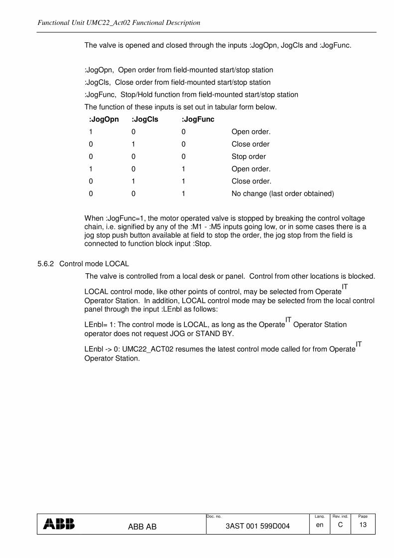
The valve is opened and closed through the inputs :JogOpn, JogCls and :JogFunc.
:JogOpn, Open order from field-mounted start/stop station
:JogCls, Close order from field-mounted start/stop station
:JogFunc, Stop/Hold function from field-mounted start/stop station
The function of these inputs is set out in tabular form below.
:JogOpn :JogCls :JogFunc
1 0 0 Open order.
0 1 0 Close order
0 0 0 Stop order
1 0 1 Open order.
0 1 1 Close order.
0 0 1 No change (last order obtained)
When :JogFunc=1, the motor operated valve is stopped by breaking the control voltage chain, i.e. signified by any of the :M1 - :M5 inputs going low, or in some cases there is a jog stop push button available at field to stop the order, the jog stop from the field is connected to function block input :Stop.
5.6.2 Control mode LOCAL
The valve is controlled from a local desk or panel. Control from other locations is blocked.
LOCAL control mode, like other points of control, may be selected from OperateIT
Operator Station. In addition, LOCAL control mode may be selected from the local control panel through the input :LEnbl as follows:
LEnbl= 1: The control mode is LOCAL, as long as the OperateIT
Operator Station
operator does not request JOG or STAND BY.
LEnbl -> 0: UMC22_ACT02 resumes the latest control mode called for from OperateIT
Operator Station.

Functional Unit UMC22_Act02 Functional Description
Doc. no. Lang. Rev. ind. Page
ABB AB 3AST 001 599D004 en C 14
The operator controls the valve through the inputs :LOpn, LCls and :LStop.
:LStop Local stop order (active low)
:LOpn Local Open order
:LCls Local Close order
The function of these inputs is set out in tabular form below.
:LStop :LOpn :LCls
0 X X Stop order. Note In order for the valve to start when LStop has been low, LStop must be set high and LOPN must make a low-to-high transition
1 0 0 No change (Last order obtained)
1 1 0 Open order
1 0 1 Close order
5.6.3 Control mode AUTO
The valve is controlled from OperateIT
Operator Station. Control from other locations is
blocked. In this mode operator controls the opening of the valve by entering the setpoint value. The valve will open and close automatically until the position reaches the setpoint value.
5.6.4 Control mode MANUAL
The valve is controlled from OperateIT
Operator Station. Control from other locations is
blocked. This is the default control mode. To open, the operator has to press the key Open. To close, operator has to press the key Close. To stop the valve, the key STOP has to be pressed.
5.6.5 Control mode EXTERNAL 1
The valve is controlled from an external signal, e.g. from a process signal. Control from other locations is blocked. This mode is e.g. used for open/close control of levels and for automatic startup and shutdown of valves.
The process controls the valve through the inputs :E1Opn, E1Cls and Stop. The operator
is able to stop the valve by issuing stop order from OperateIT
Operator Station. The control mode then changes to Manual, to prevent that the valve is reopened.
5.6.6 Control mode EXTERNAL 2
The valve is controlled from a superior program, e.g. from a group start, sequence or a process signal. Control from other locations is blocked. This mode is e.g. used for open/close control of levels and for automatic startup and shutdown of valves
The process controls the valve through the inputs: E2Opn, E2Cls and Stop. The operator
is able to stop the valve by issuing stop order from OperateIT
Operator Station. The control mode then changes to Manual, to prevent that the valve is reopened.

Functional Unit UMC22_Act02 Functional Description
Doc. no. Lang. Rev. ind. Page
ABB AB 3AST 001 599D004 en C 15
5.6.7 Control mode EXTERNAL 3
The valve si controlled from an external signal, e.g. from a group start, sequence or a process signal. Control from other locations is blocked. This mode is e.g. used for open/close control of levels and for automatic startup and shutdown of valves.
The process controls the valuve through the inputs : E3Opn, E3Cls and Stop. The
operator is able to stop the valve by issuing stop order from OperateIT
Operator Station. The control mode then changes to Manual, to prevent that the valve is reopened.
The inputs used for open, close and stop orders in control mode External 3 are:
:Stop Stop order (active low)
:E3Opn Open order
:E3Cls Close order
The function of these inputs is set out in tabular form below:
:Stop :E3Opn :E3Cls
0 X X Stop order
1 0 -> 1 0 Open order
1 0 0 ->1 Close order
:E3Opn and :E3Cls are dynamic inputs, i.e. it triggers on the rising edge.
5.6.8 Control mode DISABLED
The valve is stopped and all orders to it are blocked.
5.6.9 Control mode Panel Mode
Panel Mode is activated when the valve control is switched to Panel. The Operator Station will no longer hold any control. However operator still capable of stopping the valve or reset the alarm / fault. When the panel mode is released, the control mode will go to Manual.
5.6.10 Operator Order and Order Blocking
The different orders given by the operator can be read at the output terminal :OprOrder.
Blocking of operator order also possible from the control program by setting the corresponding bits in the terminal :OrdBlk.
5.7 Open, Close and Stop
Open, Close and stop commands for UMC22_ACT02 may originate from dialog with
OperateIT
Operator Station or from Function Block inputs, depending on the control mode
selected (See Section 5.6 Control Modes, and Table 2-1).

Functional Unit UMC22_Act02 Functional Description
Doc. no. Lang. Rev. ind. Page
ABB AB 3AST 001 599D004 en C 16
When an Open or a Close command is issued to UMC22_ACT02, it is forwarded to the motor through the Function Block output :OPN (Open order, Forwards/High/Up) and it is reversed the motor through Function Block output :CLS (Close order, Reverse/Low/Down). See Section 5.7.3 Start Order Selection. The open order on the output :OPN and the close order on the output :CLS are continuous outputs.
The main contactor of the motor acknowledges the open order :OPN or close order :CLS by setting the input :ACK1 high for Open and :ACK2 high for Close. The main contactor must acknowledge within the time determined by the input :T2.
There are certain MCC circuits which connect the ACK1 and ACK2 inside the MCC and only send one feedback to DCS system as open and close acknowledges, in this case the ACK1 on the Function Block input :ACK1 to be set to high or 1.
If the main contactor acknowledges the open order :OPN within the time T2, UMC22_ACT02 sets the open order output :OPN high and keeps it high
If the main contactor does not acknowledge the start order within the time T2, the start attempt is deemed abortive. Consequently, UMC22_ACT02 issues an alarm about the contactor failure (Main Contactor Err.) and a new attempt at starting may be made.
The contactor failure alarm indication on the object display of UMC22_ACT02 disappears when the operator acknowledges the alarm.
UMC22_ACT02 also issues an alarm about main contactor failure when the contactor acknowledges open or close orders falsely, i.e. when it sets the inputs :ACK1 high without any open order being issued. UMC22_ACT02 transmits the alarm the time T2 after the input having been set.
5.7.1 Open and Close on Torque
Inputs :ActuatorType selects opening and/or closing function (Limit sw. or Torque sw and Limit sw.)
Open �� Close Control Function
Torque Open Limit Open Limit Close Torque Close
ActuatorType = 1 - Stop Stop -
ActuatorType = 2 Stop Prepare Prepare Stop
ActuatorType = 3 - Stop Prepare Stop
ActuatorType = 4 Stop Prepare Stop -

Functional Unit UMC22_Act02 Functional Description
Doc. no. Lang. Rev. ind. Page
ABB AB 3AST 001 599D004 en C 17
5.7.2 Open, Close and Stop Order at Different Control Modes
The table below describes the commands, which can be given at the different control modes of UMC22_ACT02.
Table 2-1. Relation between commands and control modes
Order Jog Auto Manual Local Ext1 Ext2 Ext3
Input JogOpn
Open Stop
-
-
-
-
-
-
Input JogCls
Close Stop
-
-
-
-
-
-
Input Lopn
-
-
-
Open -
-
-
Input LCls
-
-
-
Close -
-
-
Input Lstop
-
-
-
Stop -
-
-
Operator Setpoint
-
0-100% -
-
-
-
-
Operator Open
-
-
Open -
-
-
-
Operator Close
-
-
Close -
-
-
-
Operator stop
Stop
Stop
Stop
Stop* Stop Stop Stop
Input E1Ref
-
-
-
-
0-100% -
-
Input E2Ref
-
-
-
-
-
0-100% -
Input E3Opn
-
-
-
-
-
-
Open
Input E3Cls
-
-
-
-
-
-
Close
Input Stop
Stop Stop - - Stop Stop Stop
* Only when local mode is selected from Operate IT keyboard

Functional Unit UMC22_Act02 Functional Description
Doc. no. Lang. Rev. ind. Page
ABB AB 3AST 001 599D004 en C 18
5.7.3 Start Order Selection
The Function Block UMC22_ACT02 has one open order and one close order outputs:
:OPN Open order, Forwards/High/up
:CLS Close order, Reverse/Low/Down
The activation of the outputs is determined as follows from the different points of control.
Control mode JOG
FB input :JogOpn
FB input :JogCls
Control mode LOCAL
FB input :LOpn
FB input :LCls
Control mode AUTO
The operator set the setpoint from OperateIT
Operator Station.
Control mode MAN
The operator issues a Start order from OperateIT
Operator Station.
Control mode Ext 1
FB Input : Ext1Ref.
Control mode Ext 2
FB Input : Ext2Ref.
Control mode Ext 3
A superior control program sets the input :E3Opn or ExCls to issue a new open or close order.
See the table below.
:E3Opn :E3Cls Stop Descr
0 0 1 No change.
1 0 1 Open order.
0 1 1 Close order
X X 0 Stop order

Functional Unit UMC22_Act02 Functional Description
Doc. no. Lang. Rev. ind. Page
ABB AB 3AST 001 599D004 en C 19
Control mode DISABLE
The valve cannot be opened.
5.8 Fault Evaluation in the Control Circuit
Evaluation is performed in the priority order M1, M2, M5, M3 and M4. This means that if the Input :M1 =0, the inputs :M2 - :M5 are not regarded etc. The signal ME interlocks the complete evaluation. ME=0 is used to prevent incorrect alarms with, for example, a total control voltage failure. The inputs M1 to M5 are to be TRUE when there are no errors. The evaluation presupposes that the control circuit consists of a number of breaking contacts in series.
5.9 Supervision of Motor Current
The input 2 in the profibus interface has information for motor current. The current supervision is obtain directly from UMC.
5.10 Alarm Handling
The alarm handling for UMC22_ACT02 can be controlled individually for the different types of fault, which can develop. For example, it is possible to block the alarms for one or more of the monitoring in the control voltage chain M1 to M5. If a dynamic blocking of certain alarms is necessary because of the requirements of the control mode, it is possible to create in the control program a suitable value and connect this to the variables in the function block.
Note, however that the FB-element itself blocks certain alarms in a number of situations.
5.11 Event handling
Event are generated for status change on the signals defined in interaction window in chapter 5.11.4 Alarm and Event Block
All Operator Events are reported by Audit Trail Functionality and not included in the FunctionBlock.
The individual text string for each event is stored in the Alarm and Event Translator aspect. This text can be NLS handled.
Functional Unit UMC22_Act02 Functional Description
Doc. no. Lang. Rev. ind. Page
ABB AB 3AST 001 599D004 en C 20
Interaction Window
The interaction window is available in the ControlIT
Control Builder. The interaction window is an engineering aid used to simplify configuration and blocking of signals not available on the faceplates. Changes to values in the Interaction window are only available in ‘Online’ mode in Control IT.
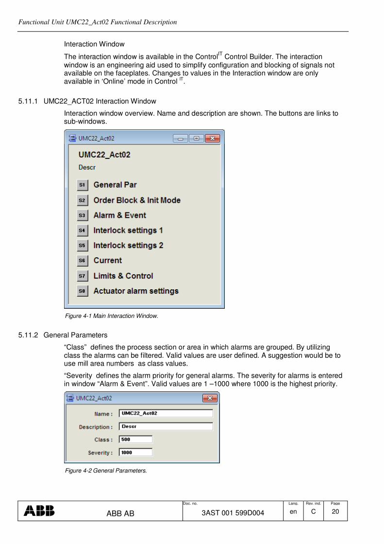
5.11.1 UMC22_ACT02 Interaction Window
Interaction window overview. Name and description are shown. The buttons are links to sub-windows.
Figure 4-1 Main Interaction Window.
5.11.2 General Parameters
“Class” defines the process section or area in which alarms are grouped. By utilizing class the alarms can be filtered. Valid values are user defined. A suggestion would be to use mill area numbers as class values.
“Severity defines the alarm priority for general alarms. The severity for alarms is entered in window “Alarm & Event”. Valid values are 1 –1000 where 1000 is the highest priority.
Figure 4-2 General Parameters.

Functional Unit UMC22_Act02 Functional Description
Doc. no. Lang. Rev. ind. Page
ABB AB 3AST 001 599D004 en C 21
5.11.3 Order Block
Blocking of operator order are entered in this window.
Figure 4-3 Order Block.
5.11.4 Alarm and Event Block
Alarm and Event blocking are entered in this window.
Alarm and Events are generated for status change on the signals defined in interaction window.
All Operator Events are reported by Audit Trail Functionality and not included in the FunctionBlock.
The individual text string for each event is stored in the Alarm and Event Translator aspect. This text can be NLS handled.
For Alarm Configuration the following values are valid
0 No Alarm or Event are generated
1 Alarm and Event are generated
2 Event is generated

Functional Unit UMC22_Act02 Functional Description
Doc. no. Lang. Rev. ind. Page
ABB AB 3AST 001 599D004 en C 22
Figure 4-4 Indication Event Block.
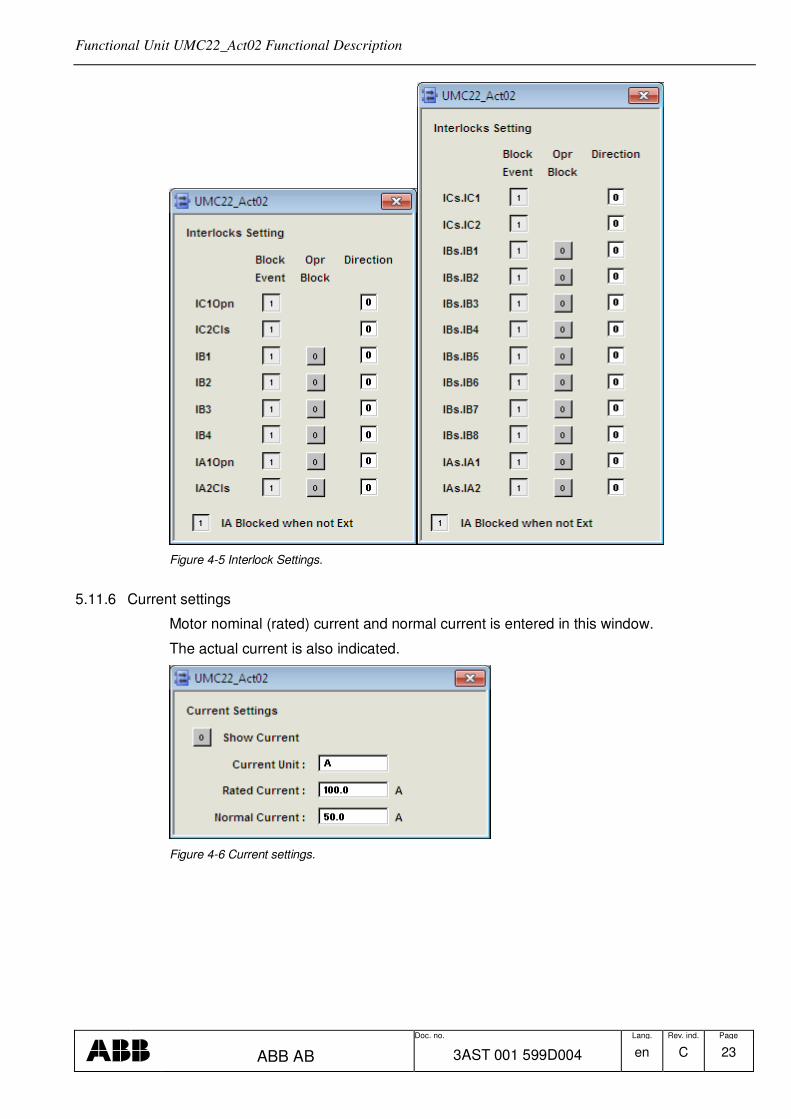
5.11.5 Interlock Settings
The different settings for interlocks are entered in this window.
Functional Unit UMC22_Act02 Functional Description
Doc. no. Lang. Rev. ind. Page
ABB AB 3AST 001 599D004 en C 23
Figure 4-5 Interlock Settings.
5.11.6 Current settings
Motor nominal (rated) current and normal current is entered in this window.
The actual current is also indicated.
Figure 4-6 Current settings.

Functional Unit UMC22_Act02 Functional Description
Doc. no. Lang. Rev. ind. Page
ABB AB 3AST 001 599D004 en C 24
5.11.7 Actuator Alarm Settings
5.11.8 Texts
The different interlock and information texts are entered in the aspect Text Properties. The length of the text is limited to about 60 characters, by the size of presentation element in the Interlock Display.
Figure 4-7 Texts.
5.11.9 Limits & Control
Max, min ranges and units are entered in this window.

Functional Unit UMC22_Act02 Functional Description
Doc. no. Lang. Rev. ind. Page
ABB AB 3AST 001 599D004 en C 25
Figure 4-9 Limits & Control.

Functional Unit UMC22_Act02 Functional Description
Doc. no. Lang. Rev. ind. Page
ABB AB 3AST 001 599D004 en C 26
6 Operator Functions
The Operator functions are divided in principle into 3 parts:
• Presentation (Display elements, Time logged properties)
• Faceplate (Dialog)
• Alarm and Event handling
• Faceplate tabs
6.1 Presentation
6.1.1 Display Elements
Display elements, which can be used for different display types, are available for use in the functional unit UMC22_ACT02.
The display elements show the status and the controls of the process with different degrees of detail and are intended for the following displays:
• Object display
• Process display
• Diagnostic display
• Interlock display
Examples of different display elements, which could be used, are given in the following sections.

Functional Unit UMC22_Act02 Functional Description
Doc. no. Lang. Rev. ind. Page
ABB AB 3AST 001 599D004 en C 27
6.1.1.1 Object Display
Figure 5-1. Object Display.

Functional Unit UMC22_Act02 Functional Description
Doc. no. Lang. Rev. ind. Page
ABB AB 3AST 001 599D004 en C 28
6.1.1.2 Process Display
Figure 5-2. UMC22_ACT02 Graphic elements
6.1.1.3 Diagnostic Display

Functional Unit UMC22_Act02 Functional Description
Doc. no. Lang. Rev. ind. Page
ABB AB 3AST 001 599D004 en C 29
6.1.1.4 Diagnostic configuration
6.1.1.5 Interlock Display
This display shows the actual status of all Interlock. The operator can override individual interlocks or all interlock.
Interlocks that can be overrided must be set to Blockable. This can be done from this display it the user has permission Configure or from the Interaction Window see chapter 5.11.5.
Start Interlock, Block Event and IA Blocked when no in E1 or E2 mode are parameters that can be set from this display if the user has Permission Configure or from Interaction Window.

Functional Unit UMC22_Act02 Functional Description
Doc. no. Lang. Rev. ind. Page
ABB AB 3AST 001 599D004 en C 30
6.1.2 Time-logged Properties
Measured values stored can be presented graphically in the form of curves on the display screen. Such a display, a Trend display, can consist of 1- 4 curves. All properties for the object UMC22_ACT02 are available to be logged on the trend curves.

Functional Unit UMC22_Act02 Functional Description
Doc. no. Lang. Rev. ind. Page
ABB AB 3AST 001 599D004 en C 31
Figure 5-3 Trend Curve
Figure 5-4 Extended Faceplate (T Curve)
6.2 Faceplate(Dialog)
The display screen is supplemented with a mouse and keyboard for operator communication with the functional unit/object.
By using OperateIT
Operator Station the operator can view and control the process through faceplates. The dialogue consists of buttons, indicators and graphic presentations within a Faceplate. A faceplate has three levels of dialogue, which are presented by the following three runtime views:
• Reduced Faceplate, where the size and contents typically have been optimized to cover most of the normal process operator actions. Minimum dialogue. This is the default view.
• Faceplate, which typically covers all normal process operator actions. This view is disabled as default.

Functional Unit UMC22_Act02 Functional Description
Doc. no. Lang. Rev. ind. Page
ABB AB 3AST 001 599D004 en C 32
• Extended Faceplate, with functions and information intended for the process engineer or the advanced operator. Maximum dialogue.

Functional Unit UMC22_Act02 Functional Description
Doc. no. Lang. Rev. ind. Page
ABB AB 3AST 001 599D004 en C 33
6.3 Alarm and Event Handling
6.3.1 General
This section contains a description of all alarms and events in the functional unit UMC22_ACT02.
When a measured value deviates from the controllers limits or fails an alarm and an event
is generated and can be viewed on the OperateIT
Operator Station. The alarms are indicated in the faceplate, object display and in the alarm and event list.
The alarm limits for UMC22_ACT02 can be controlled individually
The time stamping of the alarm is done when the function block is executed.
Functional Unit UMC22_Act02 Functional Description
Doc. no. Lang. Rev. ind. Page
ABB AB 3AST 001 599D004 en C 34
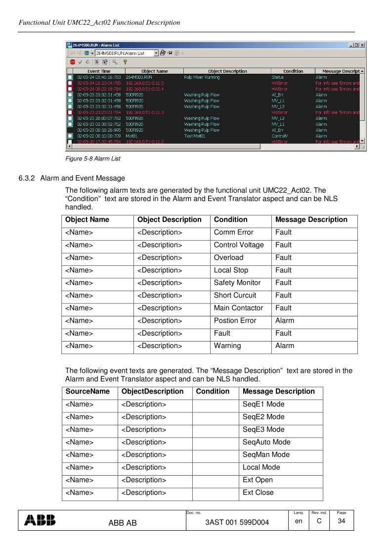
Figure 5-8 Alarm List
6.3.2 Alarm and Event Message
The following alarm texts are generated by the functional unit UMC22_Act02. The “Condition” text are stored in the Alarm and Event Translator aspect and can be NLS handled.
Object Name Object Description Condition Message Description
<Name> <Description> Comm Error Fault
<Name> <Description> Control Voltage Fault
<Name> <Description> Overload Fault
<Name> <Description> Local Stop Fault
<Name> <Description> Safety Monitor Fault
<Name> <Description> Short Curcuit Fault
<Name> <Description> Main Contactor Fault
<Name> <Description> Postion Error Alarm
<Name> <Description> Fault Fault
<Name> <Description> Warning Alarm
The following event texts are generated. The “Message Description” text are stored in the Alarm and Event Translator aspect and can be NLS handled.
SourceName ObjectDescription Condition Message Description
<Name> <Description> SeqE1 Mode
<Name> <Description> SeqE2 Mode
<Name> <Description> SeqE3 Mode
<Name> <Description> SeqAuto Mode
<Name> <Description> SeqMan Mode
<Name> <Description> Local Mode
<Name> <Description> Ext Open
<Name> <Description> Ext Close

Functional Unit UMC22_Act02 Functional Description
Doc. no. Lang. Rev. ind. Page
ABB AB 3AST 001 599D004 en C 35
<Name> <Description> Ext Stop
<Name> <Description> IC1 On
<Name> <Description> IC1 Off
<Name> <Description> IC2 On
<Name> <Description> IC2 Off
<Name> <Description> IB1 On
<Name> <Description> IB1 Off
<Name> <Description> IB2 On
<Name> <Description> IB2 Off
<Name> <Description> IB3 On
<Name> <Description> IB3 Off
<Name> <Description> IB4 On
<Name> <Description> IB4 Off
<Name> <Description> IA1 Opn On
<Name> <Description> IA1 Opn Off
<Name> <Description> IA2 Cls On
<Name> <Description> IA2 Cls Off
<Name> <Description> Limit Sw Open
<Name> <Description> Limit Sw Close
<Name> <Description> Alarm Acknowledge
<Name> <Description> Alarm Control Block
6.3.3 Diagnostic events
This event can not be blocked.
SourceName ObjectDescription Condition Message Description
<Name> <Description> Fault Input Signal
<Name> <Description> Self Test Failed
<Name> <Description> Relay 0 Check-back Fault
<Name> <Description> Relay 1 Check-back Fault
<Name> <Description> Relay 2 Check-back Fault
<Name> <Description> Current Check-back Fault
<Name> <Description> Parameter out of Range
<Name> <Description> Communication Fault

Functional Unit UMC22_Act02 Functional Description
Doc. no. Lang. Rev. ind. Page
ABB AB 3AST 001 599D004 en C 36
<Name> <Description> Motor Blocked
<Name> <Description> Overload (trip) Fault
<Name> <Description> Reversing Lockout Time Running
<Name> <Description> Cooling Time Running
<Name> <Description> Motor Current Low Threshold
<Name> <Description> Motor Current High Threshold
<Name> <Description> Sametime Open LS and Close LS
<Name> <Description> Run-time exceeded
<Name> <Description> Open TS ->0 but not Open LS
<Name> <Description> Close LS ->0 not within 3s after Open cmd
<Name> <Description> Open LS ->0 not within 3s after Close cmd
<Name> <Description> Close LS disappear without Open cmd
<Name> <Description> Open LS disappear without Close cmd
<Name> <Description> PTC Temperature
<Name> <Description> PTC Wire Break
<Name> <Description> PTC Short Circuit
<Name> <Description> Earth Fault
<Name> <Description> Wrong Device Address
<Name> <Description> Fault on DI0
<Name> <Description> Fault on DI1
<Name> <Description> Fault on DI2
<Name> <Description> Emergency Start Prepared
<Name> <Description> Self Test Running
<Name> <Description> Parameter Unknown
6.4 Faceplate tabs
6.4.1 Alarm and Event Blocking
By using the extended faceplate it is possible for the process engineer to block alarms and alarm printouts. When the block alarm and block printout check boxes are active then

Functional Unit UMC22_Act02 Functional Description
Doc. no. Lang. Rev. ind. Page
ABB AB 3AST 001 599D004 en C 37
all alarms are blocked as indicated by the yellow text in the indicator button row and by the limit indicator on the bar graph.
Figure 5-9 Extended Faceplate (Block) Figure 5-10 Extended Faceplate (Signals)
6.4.2 Limits
Figure 5-11 Extended Faceplate (Limits)

Functional Unit UMC22_Act02 Functional Description
Doc. no. Lang. Rev. ind. Page
ABB AB 3AST 001 599D004 en C 38
6.4.3 Info Text
Figure 5-12 Extended Faceplate Element (Info text).

Functional Unit UMC22_Act02 Functional Description
Doc. no. Lang. Rev. ind. Page
ABB AB 3AST 001 599D004 en C 39
REVISION
Rev. Page (P) Chapt. (C)
Description Date Dept./Init.
A First version B Rev 5.0-1 Interlock functionality is updated 081205/BP C Update Rev 5.1/0 101103/BP