
FumeFX
172
-
Upload
marcin-steplowski -
Category
Documents
-
view
5.159 -
download
6
Transcript of FumeFX


iii
Table Of Contents Introduction............................................................................................................................1
Welcome.............................................................................................................................1 Welcome.............................................................................................................................3 FumeFX Overview................................................................................................................8 Getting Started..................................................................................................................11 Support and Contact Information........................................................................................15
Stay in Contact...............................................................................................................15 Technical Support Information ........................................................................................16
Reference.............................................................................................................................19 The FumeFX Grid...............................................................................................................19 The FumeFX Grid...............................................................................................................25 FumeFX UI Dialog..............................................................................................................31
FumeFX UI Overview......................................................................................................31 General..........................................................................................................................34 Simulation......................................................................................................................38 Rendering ......................................................................................................................42 Illumination ...................................................................................................................50 Objects, Sources and Warps ...........................................................................................53
FumeFX Sources................................................................................................................70 Source Basics.................................................................................................................70 FumeFX Simple Source ...................................................................................................72 FumeFX Object Source ...................................................................................................76 FumeFX Particle Source ..................................................................................................80 FumeFX Source Controllers .............................................................................................84
FumeFX Output Preview Window........................................................................................86 Preview Window.............................................................................................................86
Gravity Vectors ..................................................................................................................88 Gravity Vectors...............................................................................................................88
FumeFX Particle Flow Operators .........................................................................................89 FumeFX Particle Flow Operators......................................................................................89
FumeFX Thinking Particle Operators ...................................................................................95 FumeFX Thinking Particles Operators...............................................................................95
FumeFX Preferences ..........................................................................................................98 Preferences....................................................................................................................98
FusionWorks Renderer ..................................................................................................... 101 FusionWorks Renderer.................................................................................................. 101
Render Elements ............................................................................................................. 103 Render Elements .......................................................................................................... 103
MAXScripting FumeFX ...................................................................................................... 104 MAXScript & FumeFX.................................................................................................... 104
Tips and Tricks ................................................................................................................ 114 Tips and Tricks............................................................................................................. 114
AFC and Gradient Control................................................................................................. 116 AFC and Gradient Control ............................................................................................. 116
Tutorials ............................................................................................................................. 121 Tutorial 1: Candle Flame .................................................................................................. 121 Tutorial 1: Candle Flame .................................................................................................. 132 Tutorial 02: Plasma Vent .................................................................................................. 143 Tutorial 03: Cigarette Smoke............................................................................................ 153 Tutorial 04: Burning Tea .................................................................................................. 158

Printed Documentation
iv
Index ................................................................................................................................. 165
1
Introduction
Welcome
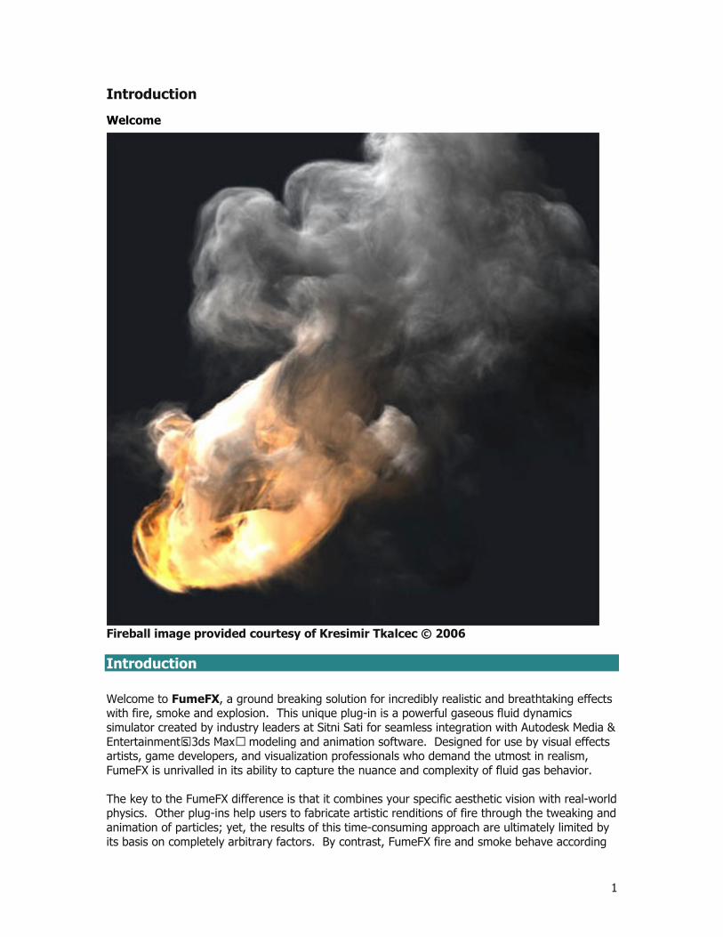
Fireball image provided courtesy of Kresimir Tkalcec © 2006 Introduction Welcome to FumeFX, a ground breaking solution for incredibly realistic and breathtaking effects with fire, smoke and explosion. This unique plug-in is a powerful gaseous fluid dynamics simulator created by industry leaders at Sitni Sati for seamless integration with Autodesk Media & Entertainment’s 3ds Max™ modeling and animation software. Designed for use by visual effects artists, game developers, and visualization professionals who demand the utmost in realism, FumeFX is unrivalled in its ability to capture the nuance and complexity of fluid gas behavior. The key to the FumeFX difference is that it combines your specific aesthetic vision with real-world physics. Other plug-ins help users to fabricate artistic renditions of fire through the tweaking and animation of particles; yet, the results of this time-consuming approach are ultimately limited by its basis on completely arbitrary factors. By contrast, FumeFX fire and smoke behave according

Printed Documentation
2
to the laws of fluid dynamics and react to relevant physical forces, such as temperature and gravity. This means you can produce realistic voxel-based simulations with greater speed and ease than ever before. Furthermore, the combination of a dynamic feature set, intuitive user interface, and open architecture offer the performance and flexibility to enhance virtually any pipeline. Simply put, there is no other combustion effects tool that can compete with physics simulation power in this plug-in. This reference guide is organized mainly by functional areas:
For new users of FumeFX, the best place to begin is the Introduction. Here you'll get a brief computational fluid dynamics lesson and the thought processes you should go through when setting up scenes for simulations. It is strongly recommended that you go through this section prior to doing the main tutorials.
For specific information about FumeFX’s various controls and settings, you should go to the Reference Section. This section will give you detailed explanations of what each component within the FumeFX user interface does, and how each one relates to the entire system.
Finally, within this document is a complete set of Tutorialsto help get you up to speed with FumeFX quickly.

Introduction
3
Welcome
Fireball image provided courtesy of Kresimir Tkalcec © 2006 Introduction Welcome to FumeFX, a ground breaking solution for incredibly realistic and breathtaking effects with fire, smoke and explosion. This unique plug-in is a powerful gaseous fluid dynamics simulator created by industry leaders at Sitni Sati for seamless integration with Autodesk Media & Entertainment’s 3ds Max™ modeling and animation software. Designed for use by visual effects artists, game developers, and visualization professionals who demand the utmost in realism, FumeFX is unrivalled in its ability to capture the nuance and complexity of fluid gas behavior. The key to the FumeFX difference is that it combines your specific aesthetic vision with real-world physics. Other plug-ins help users to fabricate artistic renditions of fire through the tweaking and animation of particles; yet, the results of this time-consuming approach are ultimately limited by its basis on completely arbitrary factors. By contrast, FumeFX fire and smoke behave according to the laws of fluid dynamics and react to relevant physical forces, such as temperature and
Printed Documentation
4
gravity. This means you can produce realistic voxel-based simulations with greater speed and ease than ever before. Furthermore, the combination of a dynamic feature set, intuitive user interface, and open architecture offer the performance and flexibility to enhance virtually any pipeline. Simply put, there is no other combustion effects tool that can compete with physics simulation power in this plug-in. This reference guide is organized mainly by functional areas:
For new users of FumeFX, the best place to begin is the Introduction. Here you'll get a brief computational fluid dynamics lesson and the thought processes you should go through when setting up scenes for simulations. It is strongly recommended that you go through this section prior to doing the main tutorials.
For specific information about FumeFX’s various controls and settings, you should go to the Reference Section. This section will give you detailed explanations of what each component within the FumeFX user interface does, and how each one relates to the entire system.
Finally, within this document is a complete set of Tutorialsto help get you up to speed with FumeFX quickly.

Introduction
5
License Agreement Sitni Sati d.o.o End User License Agreement (EULA) for FumeFX IMPORTANT -- READ CAREFULLY: This Sitni Sati d.o.o End User License Agreement ("License Agreement") is a legal agreement between you (either an individual or an entity) and Sitni Sati d.o.o, a company under Croatian law with residence in Zagreb, Croatia. By clicking on the "Accept" button, installing, copying or otherwise using FumeFX, you agree to be bound by the terms of this License Agreement. If you do not agree to the terms of this License Agreement, click on the "Cancel" button and/or do not install FumeFX. ******************************************************** NOTE: THIS PRODUCT MUST BE REGISTERED WITHIN 30 DAYS BEFORE YOU CAN CONTINUE USING THE SOFTWARE FOR AN UNLIMITED TIME ******************************************************** 1. General This is a license agreement and NOT an agreement for sale. Under this contract Sitni Sati d.o.o grants to you a non-exclusive license to use FumeFX, which is software and documentation. FumeFX itself as well as the copy of FumeFX or any other copy you are authorized to make under this contract remain the property of Sitni Sati d.o.o at all times. 2. Use of FumeFX (1) Sitni Sati d.o.o grants you a nonexclusive, nontransferable license to use FumeFX and its manual and other accompanying printed material and “online” or electronic documentation with equipment owned by you or under your control, according to the terms and conditions of this Agreement. This Agreement permits a single user to install and use FumeFX on only one computer at one location at any one time. (2) If FumeFX is identified as a demonstration, evaluation, or NFR version, you may use it only for the purpose of commercial evaluation and demonstration. Such licenses are generated for a specific fixed time period. After a NFR license has been expired, all related documentation and data must be destroyed or sent back to Sitni Sati d.o.o or the reseller who handled the NFR version. You may not use it for commercial, professional, or for-profit purposes. 3. Multiple use and network operation If this Software is a Network Version, you may use it only over an internal local area network environment with a Floating License Tool, and you may install and operate FumeFX on a single server computer in a single location which may be accessed by other computers, or on an individual computer, as a multiple-user installation with either: (1) The maximum number of concurrent users being one (1), so that multiple individuals may access or use FumeFX, but that only one person at a time may do so, or (2) The maximum number of concurrent users being more than one (1), in which case you must purchase single seat licenses for each additional concurrent user.
Printed Documentation
6
The use of software or any device that reduces the number of computers/devices which access FumeFX's licensing tool when used in a Server configuration may interfere or damage the licensing tool or prevent FumeFX from running properly. In no case will such a device "reduce" or prevent you from buying the number of single seat licenses required. 4. Transfer (1) You may not rent, sell, lease, sublicense or lend FumeFX or documentation. 5. You May Not: (1) Copy or use FumeFX or Documentation except as permitted by this Agreement. (2) Reverse engineer, decompile, or disassemble FumeFX except to the extent permitted by law where this is indispensable to obtain the information necessary to achieve interoperability of an independently created program with FumeFX or with another program and such information is not readily available from Sitni Sati d.o.o or elsewhere. (3) Install or use FumeFX on the Internet or over a wide area network, including, without limitation, use in connection with a Web based render farm or similar service. (4) Remove, alter, or obscure any proprietary notices, labels, or marks from FumeFX or documentation. (5) Utilize any equipment, device, software, or other means designed to circumvent or remove any form of copy protection used by Sitni Sati d.o.o in connection with FumeFX, or use FumeFX together with any authorization code, serial number, or other copy protection device not supplied by Sitni Sati d.o.o directly or through an authorized reseller. 6. Limited warranty (1) SPECIAL EFFECTS AND RENDERING PLUG-INS ARE TOOLS INTENDED TO BE USED BY TRAINED PROFESSIONALS ONLY. SITNI SATI D.O.O WARRANTS THAT FumeFX WILL PERFORM IN ACCORDANCE WITH THE DOCUMENTATION. SITNI SATI D.O.O CANNOT WARRANT THAT FumeFX WILL WORK TOGETHER WITH OTHER SOFTWARE AND PLUG-INS FROM OTHER 3RD PARTY DEVELOPERS, BECAUSE OF THE COMPLEXITY OF SUCH INTERACTIONS BETWEEN DIFFERENT OPERATING SYSTEMS OR SOFTWARE PACKAGES. THE USER MAY HOWEVER IMMEDIATELY REPORT SUCH INCOMPATIBILITIES FOR FURTHER INSPECTION BY SITNI SATI D.O.O SUCH A REPORT HAS TO BE DONE IN WRITING. 7. Warranty Disclaimer THE INFORMATION IS PROVIDED "AS IS" WITHOUT WARRANTY OF ANY KIND. SITNI SATI D.O.O DISCLAIMS ALL WARRANTIES, EITHER EXPRESSED OR IMPLIED, INCLUDING THE WARRANTIES OF MERCHANTABILITY AND FITNESS FOR A PARTICULAR PURPOSE. IN NO EVENT SHALL SITNI SATI D.O.O, ITS SUPPLIERS, TURBO SQUID, INC., OR AUTODESK MEDIA & ENTERTAINMENT, A DIVISION OF AUTODESK BE LIABLE FOR ANY DAMAGES WHATSOEVER INCLUDING DIRECT, INDIRECT, INCIDENTAL, CONSEQUENTIAL, LOSS OF BUSINESS PROFITS OR SPECIAL DAMAGES, EVEN IF SITNI SATI D.O.O OR ITS SUPPLIERS, TURBO SQUID, INC., OR AUTODESK MEDIA & ENTERTAINMENT, A DIVISION OF AUTODESK HAVE BEEN ADVISED OF THE POSSIBILITY OF SUCH DAMAGES. SOME STATES DO NOT ALLOW THE EXCLUSION OR LIMITATION OF LIABILITY FOR CONSEQUENTIAL OR INCIDENTAL DAMAGES SO THE FOREGOING LIMITATION MAY NOT APPLY. 8. Confidentially
Introduction
7
All Licensing information, including license files, descriptions of code activation and written instructions of any kind created by SITNI SATI D.O.O are only intended for the licensed user of FumeFX and no one else. Such information may not be spread or distributed in any form to other users. 9. Registration Data For the purpose of customer registration and control of proper use of the programs Sitni Sati d.o.o and TurboSquid inc. will store personal data of the users in accordance with the Croatian law on Personal Privacy and Data Protection. This data may only be used for the above-mentioned purposes and will not be accessible to third parties 10. Other If any provision of this Agreement is found to be invalid or otherwise unenforceable, the further conditions of this Agreement will remain fully effective and the parties will be bound by obligations which approximate, as closely as possible, the effect of the provision found invalid or unenforceable, without being themselves invalid or unenforceable. BY INSTALLING AND AUTHORIZING THIS SOFTWARE, YOU HEREBY AGREE TO THE TERMS AND CONDITIONS PRESENTED ABOVE. 3ds Max is a registered trademark of Autodesk Media & Entertainment, a division of Autodesk Inc.

Printed Documentation
8
FumeFX Overview
Thank you for investing in FumeFX, the latest innovative and powerful plug-in designed for 3ds Max by Sitni Sati. FumeFX is a gaseous fluid dynamics simulator that allows you to create the ultimate in realistic fiery effects by putting the power of physics at your fingertips. Whether you need a flickering candle, smoldering campfire, rolling inferno, or violent explosion, your results with this plug-in will defy the viewer’s eye. We hope you will find that FumeFX is everything you have been looking for. Our software policy has always been to integrate powerful software design with ease-of-use so that you can begin to utilize our products quickly and easily. To achieve this, we have included timesaving features, such as an intuitive user interface and a simulation preview window. Another key feature is our new FusionWorks renderer – essentially a fast blender for atmospheric effects that you can use to blend the results of all AfterWorks plug-ins. And, for those who want to get the most out of FumeFX: the plug-in’s open functionality allows you to MAXScript almost anything. FumeFX is undoubtedly different from other plug-ins you may have tried. So, before you begin, we highly recommend that you read the following section, which summarizes some of the high-level concepts and physics behind FumeFX. We have also provided an excellent set of tutorials that demonstrates basic workflow, tips, and techniques. These resources will quickly prepare you to make the most of this tool’s extraordinary potential. We hope you will enjoy using this powerful new tool! How FumeFX Works As earlier mentioned, the reason that FumeFX can accurately simulate the behavior of fire and smoke is because it is based on the laws of fluid dynamics. This means that you can now mimic real combustion without studying physics. Still, in order to understand the basic concepts behind

Introduction
9
FumeFX, it may help to spend a brief moment to consider the influence of physics on the program’s design. To begin, fluid gases, such as fire and smoke, do not have a set size or shape. So, in physics, a fluid is generally regarded as a continuum, rather than as a bunch of individual molecules. FumeFX approaches fluid from the same viewpoint; it operates on an adaptive 3D grid of voxels (volumetric pixels), which mimics a continuum of fluid. This grid expands and shrinks with the movement or absence of fluid. Also, in the real world combustion is a combination of fuel, temperature, smoke, and velocity; accordingly these are the same properties that affect your simulation in FumeFX. Their values are defined in each voxel of the FumeFX grid. And, of course, external forces, such as gravity or solid objects, can also be used to influence your effects. These combined parameters will determine how your simulation behaves. So, for example, smoke is affected by gravity and temperature is affected by buoyancy. The higher the temperature of the smoke, the faster it will rise, depending on buoyancy parameter. And, the denser the smoke is, the faster it will fall, depending on the force of gravity. Of course, physics aside, FumeFX also includes a wide array of options that allow you control the rendered appearance of your simulation. These include parameters such as colors, opacity, and shadows, all of which allow you to tailor your effect to your aesthetic needs. The FumeFX Grid The FumeFX grid is a core element of FumeFX. It consists of an area of voxels that will be affected by simulation. By choosing the size of this grid, you set the maximum limits for the simulation area. Within the boundaries of this space, an adaptive grid expands and shrinks to contain just those voxels that are producing fluid. Grid detail level is set with grid spacing. If you cut the spacing in half, you will increase detail, but also dramatically increase the size, memory, and time required for simulation. You add this grid into your scene from the main Command Panel in 3ds Max. To do this, first choose the Create Geometry icon; then, select FumeFX from the drop down menu of categories. Now you can click and drag in the active viewport to create the grid. . Simulation Simulations are created through the calculations of the FumeFX solver. This proceeds in steps that correspond to 3ds Max frames; or, if you require greater accuracy and stability, it can also simulate in multiple steps per frame. Simulation stems from whatever object that you pick as your FumeFX Object Source. In the parameters for this source, you will choose the values for smoke, temperature, fire, and velocity – the main elements of simulation. During simulation these values are set at every voxel that the source touches. At the beginning of each step, the FumeFX solver applies any external influences that are within the boundaries of the grid. These can be FumeFX sources that add fire, smoke or movement; space warps that will force fluid movement similar to the way in which they force particles; or even solid objects that block or interrupt fluid movement. Then, forces such as gravity and buoyancy are applied. And finally, “post-processing” is done; this is where forces such as dissipation and diffusion are applied, fuel is burned and smoke is created.
Printed Documentation
10
The results of the simulation are saved at the end of each step in files – with the extension “.fxd” – that remember the values for each voxel. Simulation is done with floating point precision; output files are saved with half that precision. You will need a lot of disk space for long and detailed simulations, perhaps tens of Gigabytes (see Memory Requirements for more details). Memory requirements and recommendations FumeFX operates on three-dimensional grid of voxels; accordingly, a grid of 10x10x10 means 1000 voxels. Each voxel requires one float (4 bytes) per Smoke, Temperature, or Fuel/Fire channel, or three floats (12 bytes) per Velocity or Fluid Mapping channel. During simulation, FumeFX uses approximately double the memory than is needed for output of the results. And, you will need roughly twice that amount, should you choose to export texture coordinates. Memory usage of the simulation is displayed on the status window while the simulation runs. 64-bit Windows 32-bit Windows limits the memory available per process to 2GB (or 3GB). That limit does not exist on 64-bit Windows. So, 64-bit 3ds Max will have to be used as well. 3GB address space Before starting, users of 32-bit Microsoft Windows XP with 2GB of Memory can modify their boot.ini with /3Gb to allow FumeFX to use 3GB of space instead of just 2. More information is available at the following link: http://support.microsoft.com/kb/833721#XSLTH3253121121120121120120 Swapping to disk FumeFX can swap simulation of practically any size to disk. However, since disk swapping can increase simulation times by up to 10-20x, it is highly recommended to keep within 150% of available RAM. The disk must have enough space to hold the entire simulation step while it is being processed. Additionally, make sure that you select a path for temporary files in the FumeFX preferences. Getting Started with FumeFX

Introduction
11
Getting Started
Fireball image provided courtesy of Roman Schmidt © 2006 FumeFX operates within the 3ds Max environment as an integrated set of floating dialogs and viewport gizmos that define a complex, computational fluid dynamic simulation. However, instead of forcing users to deal with foreign concepts and difficult physics, FumeFX has been designed with artists in mind. We know that everyone dreads learning a new interface, so we've tried to make it as familiar and intuitive as possible, and anyone who's used another Sitni Sati plug-in (like AfterBurn or DreamScape) should feel right at home in no time. There are four main parts to using FumeFX:
The FumeFX Grid The FumeFX Sources The FumeFX UI floating dialog The Interactive Preview Window
The following is a breakdown of these major interface elements, where they are, and how to find key information on them. The FumeFX Grid The FumeFX Grid is the heart of the entire FumeFX system. It is the part of FumeFX that manages all of the simulation parameters, where you add objects, particle systems, forces and sources that will participate in the simulation and then calculates and outputs all of the data for final render. It exists as a simple, non-rendering primitive that defines the volume within which the simulation is going to be run.

Printed Documentation
12
The FumeFX Grid To learn more about the FumeFX Grid and it's controls, click HERE. FumeFX Sources Where the FumeFX Grid handles all of the heavy lifting once a scene has been set up and is ready for simulation, the system can't do anything without sources to simulate with. Sources in FumeFX define everything from a point of origin for the simulation to begin (the "fire starter"), to more complex collision objects and forces (like Wind and Gravity) that will react with the simulation as it progresses. Unlike particle based effects which fake smoke and fire behavior, FumeFX uses true physics so that selected objects can spontaneously burst into flame and react to other scene elements without the need for cheats. These sources are the building blocks upon which simulations are built. In order to associate objects with FumeFX, you create helpers to make the simulation engine "aware" of the selected objects within the FumeFX Grid volume. These non-rendering helpers have additional parameters associated with them so that users can fine tune how the source will affect the final simulation.
Simple, Object & Particle Source Helpers To learn more about FumeFX Sources, click HERE.
Introduction
13
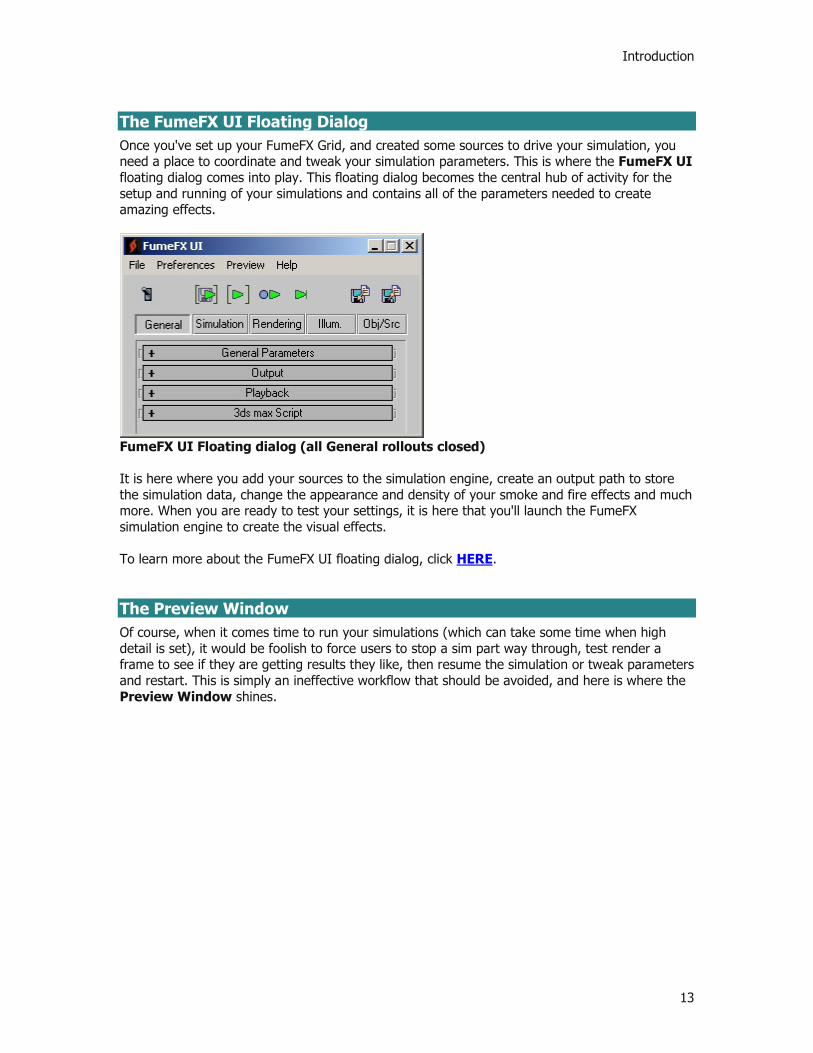
The FumeFX UI Floating Dialog Once you've set up your FumeFX Grid, and created some sources to drive your simulation, you need a place to coordinate and tweak your simulation parameters. This is where the FumeFX UI floating dialog comes into play. This floating dialog becomes the central hub of activity for the setup and running of your simulations and contains all of the parameters needed to create amazing effects.
FumeFX UI Floating dialog (all General rollouts closed) It is here where you add your sources to the simulation engine, create an output path to store the simulation data, change the appearance and density of your smoke and fire effects and much more. When you are ready to test your settings, it is here that you'll launch the FumeFX simulation engine to create the visual effects. To learn more about the FumeFX UI floating dialog, click HERE. The Preview Window Of course, when it comes time to run your simulations (which can take some time when high detail is set), it would be foolish to force users to stop a sim part way through, test render a frame to see if they are getting results they like, then resume the simulation or tweak parameters and restart. This is simply an ineffective workflow that should be avoided, and here is where the Preview Window shines.

Printed Documentation
14
Instead of having to wait, the FumeFX Preview window lets you see a quick render of the simulated frames as they calculate. What's more, is that once a simulation has finished, instead of having to tweak parameters (such as color and density) blindly, the FumeFX Preview Window will let you see how your changes will affect the resultant frame. Since the simulation data for the frames in the Preview Window is stored on hard disk, it makes tweaking a very interactive process, which ultimately will speed your workflow and output. To learn more about the FumeFX Preview Window, click HERE.
Introduction
15
Support and Contact Information
Stay in Contact
FumeFX is under constant development and we need your help to improve it. If you think of features you'd like to see within FumeFX, please let us know. We'd love to hear from you and we will always answer your emails. It doesn't matter if you just want to write in to give us your opinion. Tell us what you think and what you would like to see in upcoming releases. The easiest way to contact us is by email. Our contact information is as follows: Sitni Sati d.o.o. Kutnjacki put 15, Zagreb 10000, Croatia Ph: +385 (0)1 3865 284 Fx: +385 (0)1 3865 287 http://www.afterworks.com Email: [email protected]
NOTE: If you are looking for technical support for FumeFX, then please go HERE. Copyright Notice The copyright of FumeFX and the manual is owned by Sitni Sati d.o.o. Reproduction of the software or associated digital information of this manual is forbidden, unless confirmed and signed in writing by Sitni Sati d.o.o. All Rights are Reserved. FumeFX, AfterBurn, DreamScape, Enlight, and ScatterVL Pro are trademarks of Sitni Sati d.o.o. FumeFX © Sitni Sati d.o.o 2006 This software is designed to work as a plug-in only for 3ds Max™.

Printed Documentation
16
Technical Support Information
General Technical Support Turbo Squid, Inc. is pleased to have been chosen as Autodesk Media & Entertainment's partner for the Autodesk Certified Animation Plug-in Program, and as part of our commitment to the 3ds Max users and our development partners, we are proud to announce that we are offering free email-based technical support for all Autodesk Certified Animation Plug-in tools. The most important goal behind our technical support endeavors is to ensure that you have a good experience with your software, and in those cases where there are problems, that you have a good experience with Turbo Squid in getting your issues resolved quickly. If you are having any difficulties with your Autodesk Certified Animation Plug-in products, then feel free to contact our support team at the following online site:
Online Web-based Support System: http://www.turbosquid.com/Support From this section of our website, fill out an online Product Support Ticket, so our technical support staff can get you an answer. Please be sure to include as much specific information as possible when reporting errors including the following:
The Autodesk Certified Animation Plug-in tool that is giving you trouble along with your product Serial Number (without your serial number, Turbo Squid will NOT be able to assist you)
Hardware configuration (single / dual motherboard, amount of RAM, etc.) Operating System (including language and Service Packs) Version of 3ds Max you are using Step-by-step description to reproduce the problem Other miscellaneous notes, plug-ins present and observations A *.max file that shows the problem A daytime phone and return email address (if different from the one sent in on)
When sending files for diagnosis, please be sure to compress them with a Windows utility like WinZip or WinAce. This will make transfer a much faster, and simpler process. Online Forums You are also encouraged to visit the Turbo Squid forums to get answers from fellow users and from the developers directly. This online community has been set up specifically to make sure that you get the help you need, when you need it. Additionally, a new dedicated forum for FumeFX is being set up at www.cgfluids.com - here you can get answers from industry veterans who have used FumeFX in production. FAQs Within the Turbo Squid website are FAQs for all of the Autodesk Certified Animation Plug-ins, including FumeFX. Check here for answers to common questions. As problems are reported and solved, answers to these issues will also be added to this FAQ area, so check back often.

Introduction
17
Installation & Authorization Support If you’re having difficulty installing or authorizing your new Autodesk Certified Animation Plug-in software, then you may also choose to call our technical support staff directly so that we can get you up and running quickly. If you decide to call, be sure that you have your Product Serial Number available. If you do not have it, our staff won't be able to assist you.
Phone: (504) 525-0990 Please understand this phone line is for Installation support only, and all other technical and usage support questions will be referred to email or to our support forums for assistance. Other Options Sitni Sati will continue to enhance FumeFX as part of the Autodesk Certified Animation Plug-in program. When there are new releases or updates to FumeFX, you will be informed by your authorized reseller and through direct contact from Sitni Sati, Autodesk Media & Entertainment and Turbo Squid. To best keep you informed about new releases and free updates you must be a registered user.

19
Reference
The FumeFX Grid
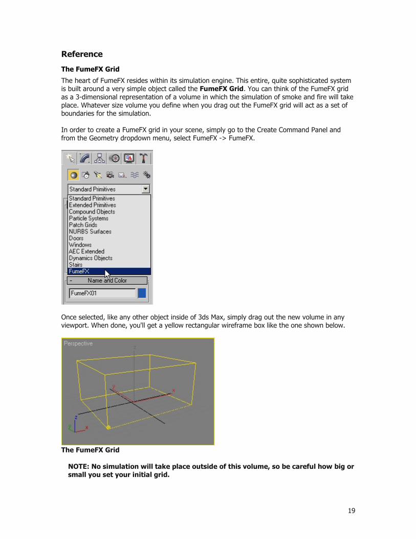
The heart of FumeFX resides within its simulation engine. This entire, quite sophisticated system is built around a very simple object called the FumeFX Grid. You can think of the FumeFX grid as a 3-dimensional representation of a volume in which the simulation of smoke and fire will take place. Whatever size volume you define when you drag out the FumeFX grid will act as a set of boundaries for the simulation. In order to create a FumeFX grid in your scene, simply go to the Create Command Panel and from the Geometry dropdown menu, select FumeFX -> FumeFX.
Once selected, like any other object inside of 3ds Max, simply drag out the new volume in any viewport. When done, you'll get a yellow rectangular wireframe box like the one shown below.
The FumeFX Grid
NOTE: No simulation will take place outside of this volume, so be careful how big or small you set your initial grid.

Printed Documentation
20
Since FumeFX is based on real-world computational fluid dynamics, something to consider is the scale of your scene. Just like other simulation engines, you will get unpredictable results if your scenes are microscopic or gigantic in scale. Imagine a matchstick simulation where the geometry is over a mile long in real-world unit - the precision and accuracy of the simulation would not be to the correct scale of the desired result, so be sure to watch the scale of your scenes. It is important to realize that within the Grid is a set of voxels (Volumetric Pixels), and the density of this volume can be manipulated to get higher or lower precision within the same space. The volume within the FumeFX container is automatically sub-divided into a set of equal sized rectangular "cells", stacked on top of one another, and each one is designed to contain data pertaining to the simulation within them. Since artists are visual by nature, users can visualize this grid at any time to get a better idea of how much detail their simulation will have.
FumeFX Volume Grid display (lower resolution)
FumeFX Volume Grid display (higher resolution)
IMPORTANT: It is important to remember that the higher the detail within the volume, the longer the amount of time it will take to run the simulation and the larger the amount of storage it will require. See the System Requirement explanation in the Overview to help you determine your storage requirements.
Once you've gotten your FumeFX Grid placed within your 3ds Max viewports, then its time to go to the Modify Command Panel. With the FumeFX Grid selected, you'll be presented with the controls and rollouts necessary to access the power within FumeFX, and also serves as a starting point for your interaction with

Reference
21
FumeFX. It contains two rollouts: General Parameters and Viewport. From these rollouts you can access other parts of the interface, edit your preferences, modify parameters of the FumeFX Grid, or control the way that your simulation appears in the 3ds Max viewports.
NOTE: You can also access the FumeFX rollouts in the Create Command Panel during the initial creation of any FumeFX Grdi object; you can use these rollouts as long as the object remains your current selection.
General Parameters Rollout The General Parameters rollout contains the parameters of your simulation area and the overall grid size. This group of controls is also available in the Floater Window; one difference is that in the Modify panel, this rollout also includes the main toolbar – your gateway to other parts of the interface.
Icon Toolbar
This group of controls lets you quickly access the basic set of FumeFX dialogs and information.
Preview - Selecting this button opens the output Preview Window. You can open the Preview Window at any time from this toolbar, the FumeFX Floater, or the FumeFX Status Window. If you open it during simulation you may have to wait until the current frame is calculated for the window to refresh.
FumeFX UI/Floater - This button opens the main part of the FumeFX user interface – the FumeFX UI floating window.
Preferences - This button opens the Preferences dialog box, which lets you quickly configure local or global parameters.
About FumeFX - Selecting this icon opens a dialog box that displays your FumeFX version and plug-in ID. You can also reauthorize the plug-in, or see if there is any news by clicking on the “Search for updates” button.
Simulation Area Group of Controls

Printed Documentation
22
In this rollout you will also find a group of controls for FumeFX grid dimensions and detail. You can also access these controls under the General tab of the FumeFX UI floating dialog. Spacing - This parameter directly affects the detail level in your simulation. Type in or use the spinner to set the spacing of the voxel-based grid. The chosen value defines voxel size; smaller voxel size allows for more voxels in simulation, which produces greater detail. Width, Length, Height - These three values set the volumetric dimensions of the FumeFX Grid, thereby establishing the boundaries for simulation within the scene. Adaptive - While enabled, the grid will expand and shrink with the movement or absence of fluid to use only the necessary portion of the overall grid space. It is highly recommended to leave this enabled because it reduces simulation time and file size. Sensitivity - When the Adaptive option is enabled, this parameter defines the boundary’s sensitivity to the production of smoke/fuel/fire. The larger the number, the tighter the adaptive box. Leave this value between 0.1 and 0.01.
NOTE: If there is a source that does not emit any matter, but just produces wind, and you want FumeFX to enlarge grid accordingly to the wind strength, set the Sensitivity value to zero.
Viewport Rollout By default, your simulation will not appear in the 3ds Max viewports. The FumeFX Preview Window is intended to give you the most accurate representation of what your simulation will look like after rendering. However, for scene layout purposes, it is sometimes helpful to view the simulation in the viewports. In the Viewport rollout, you can enable and adjust this viewport display. Enable Display - The large Enable Display button toggles the viewport display on or off. Next to this, there is a small checkbox marked with a plus sign. If this button is selected, FumeFX will continue displaying its data in the viewport even if the FumeFX object is not selected. Display Optimize Group of Controls
Reduce - Use the spinner to set the level of detail; the viewport will display every nth voxel across all 3 axes. Threshold Scale - This value acts as a multiplier for the individual threshold values of each channel. For each channel, the corresponding threshold spinner sets the minimum value that will be displayed, in FumeFX units (Smoke, Fire and Fuel), or world units (Velocities and Forces). Channel/Threshold Group of Controls
Reference
23
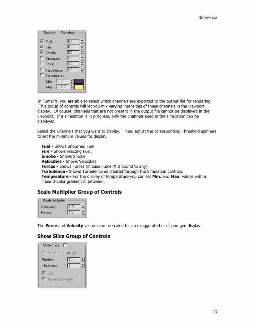
In FumeFX, you are able to select which channels are exported to the output file for rendering. This group of controls will let you mix varying intensities of these channels in the viewport display. Of course, channels that are not present in the output file cannot be displayed in the viewport. If a simulation is in progress, only the channels used in the simulation can be displayed. Select the Channels that you want to display. Then, adjust the corresponding Threshold spinners to set the minimum values for display.
Fuel - Shows unburned Fuel. Fire - Shows reacting Fuel. Smoke - Shows Smoke. Velocities - Shows Velocities. Forces - Shows Forces (in case FumeFX is bound to any). Turbulence - Shows Turbulence as created through the Simulation controls. Temperature - For the display of temperature you can set Min. and Max. values with a linear 2-color gradient in between.
Scale Multiplier Group of Controls
The Force and Velocity vectors can be scaled for an exaggerated or disparaged display. Show Slice Group of Controls
Printed Documentation
24
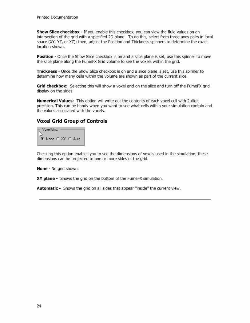
Show Slice checkbox - If you enable this checkbox, you can view the fluid values on an intersection of the grid with a specified 2D plane. To do this, select from three axes pairs in local space (XY, YZ, or XZ); then, adjust the Position and Thickness spinners to determine the exact location shown. Position - Once the Show Slice checkbox is on and a slice plane is set, use this spinner to move the slice plane along the FumeFX Grid volume to see the voxels within the grid. Thickness - Once the Show Slice checkbox is on and a slice plane is set, use this spinner to determine how many cells within the volume are shown as part of the current slice. Grid checkbox: Selecting this will show a voxel grid on the slice and turn off the FumeFX grid display on the sides. Numerical Values: This option will write out the contents of each voxel cell with 2-digit precision. This can be handy when you want to see what cells within your simulation contain and the values associated with the voxels. Voxel Grid Group of Controls
Checking this option enables you to see the dimensions of voxels used in the simulation; these dimensions can be projected to one or more sides of the grid. None - No grid shown. XY plane - Shows the grid on the bottom of the FumeFX simulation. Automatic - Shows the grid on all sides that appear "inside" the current view.
Reference
25
The FumeFX Grid
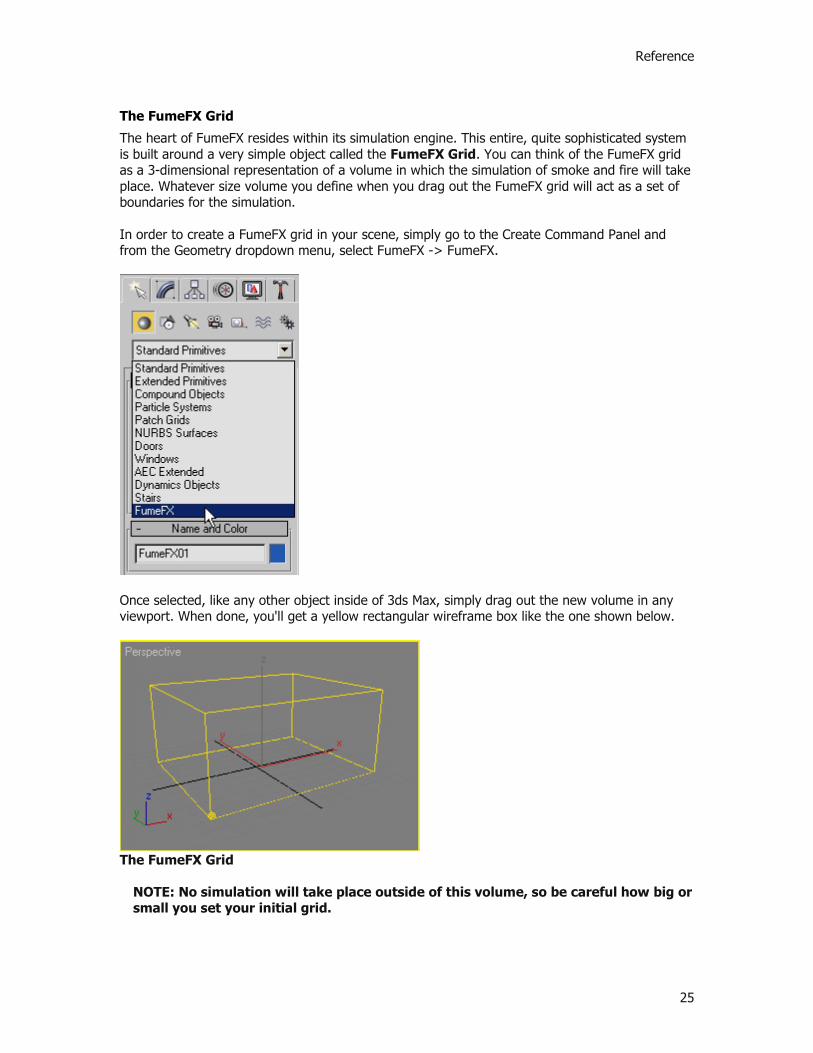
The heart of FumeFX resides within its simulation engine. This entire, quite sophisticated system is built around a very simple object called the FumeFX Grid. You can think of the FumeFX grid as a 3-dimensional representation of a volume in which the simulation of smoke and fire will take place. Whatever size volume you define when you drag out the FumeFX grid will act as a set of boundaries for the simulation. In order to create a FumeFX grid in your scene, simply go to the Create Command Panel and from the Geometry dropdown menu, select FumeFX -> FumeFX.
Once selected, like any other object inside of 3ds Max, simply drag out the new volume in any viewport. When done, you'll get a yellow rectangular wireframe box like the one shown below.
The FumeFX Grid
NOTE: No simulation will take place outside of this volume, so be careful how big or small you set your initial grid.

Printed Documentation
26
Since FumeFX is based on real-world computational fluid dynamics, something to consider is the scale of your scene. Just like other simulation engines, you will get unpredictable results if your scenes are microscopic or gigantic in scale. Imagine a matchstick simulation where the geometry is over a mile long in real-world unit - the precision and accuracy of the simulation would not be to the correct scale of the desired result, so be sure to watch the scale of your scenes. It is important to realize that within the Grid is a set of voxels (Volumetric Pixels), and the density of this volume can be manipulated to get higher or lower precision within the same space. The volume within the FumeFX container is automatically sub-divided into a set of equal sized rectangular "cells", stacked on top of one another, and each one is designed to contain data pertaining to the simulation within them. Since artists are visual by nature, users can visualize this grid at any time to get a better idea of how much detail their simulation will have.
FumeFX Volume Grid display (lower resolution)
FumeFX Volume Grid display (higher resolution)
IMPORTANT: It is important to remember that the higher the detail within the volume, the longer the amount of time it will take to run the simulation and the larger the amount of storage it will require. See the System Requirement explanation in the Overview to help you determine your storage requirements.
Once you've gotten your FumeFX Grid placed within your 3ds Max viewports, then its time to go to the Modify Command Panel. With the FumeFX Grid selected, you'll be presented with the controls and rollouts necessary to access the power within FumeFX, and also serves as a starting point for your interaction with

Reference
27
FumeFX. It contains two rollouts: General Parameters and Viewport. From these rollouts you can access other parts of the interface, edit your preferences, modify parameters of the FumeFX Grid, or control the way that your simulation appears in the 3ds Max viewports.
NOTE: You can also access the FumeFX rollouts in the Create Command Panel during the initial creation of any FumeFX Grdi object; you can use these rollouts as long as the object remains your current selection.
General Parameters Rollout The General Parameters rollout contains the parameters of your simulation area and the overall grid size. This group of controls is also available in the Floater Window; one difference is that in the Modify panel, this rollout also includes the main toolbar – your gateway to other parts of the interface.
Icon Toolbar
This group of controls lets you quickly access the basic set of FumeFX dialogs and information.
Preview - Selecting this button opens the output Preview Window. You can open the Preview Window at any time from this toolbar, the FumeFX Floater, or the FumeFX Status Window. If you open it during simulation you may have to wait until the current frame is calculated for the window to refresh.
FumeFX UI/Floater - This button opens the main part of the FumeFX user interface – the FumeFX UI floating window.
Preferences - This button opens the Preferences dialog box, which lets you quickly configure local or global parameters.
About FumeFX - Selecting this icon opens a dialog box that displays your FumeFX version and plug-in ID. You can also reauthorize the plug-in, or see if there is any news by clicking on the “Search for updates” button.
Simulation Area Group of Controls

Printed Documentation
28
In this rollout you will also find a group of controls for FumeFX grid dimensions and detail. You can also access these controls under the General tab of the FumeFX UI floating dialog. Spacing - This parameter directly affects the detail level in your simulation. Type in or use the spinner to set the spacing of the voxel-based grid. The chosen value defines voxel size; smaller voxel size allows for more voxels in simulation, which produces greater detail. Width, Length, Height - These three values set the volumetric dimensions of the FumeFX Grid, thereby establishing the boundaries for simulation within the scene. Adaptive - While enabled, the grid will expand and shrink with the movement or absence of fluid to use only the necessary portion of the overall grid space. It is highly recommended to leave this enabled because it reduces simulation time and file size. Sensitivity - When the Adaptive option is enabled, this parameter defines the boundary’s sensitivity to the production of smoke/fuel/fire. The larger the number, the tighter the adaptive box. Leave this value between 0.1 and 0.01.
NOTE: If there is a source that does not emit any matter, but just produces wind, and you want FumeFX to enlarge grid accordingly to the wind strength, set the Sensitivity value to zero.
Viewport Rollout By default, your simulation will not appear in the 3ds Max viewports. The FumeFX Preview Window is intended to give you the most accurate representation of what your simulation will look like after rendering. However, for scene layout purposes, it is sometimes helpful to view the simulation in the viewports. In the Viewport rollout, you can enable and adjust this viewport display. Enable Display - The large Enable Display button toggles the viewport display on or off. Next to this, there is a small checkbox marked with a plus sign. If this button is selected, FumeFX will continue displaying its data in the viewport even if the FumeFX object is not selected. Display Optimize Group of Controls
Reduce - Use the spinner to set the level of detail; the viewport will display every nth voxel across all 3 axes. Threshold Scale - This value acts as a multiplier for the individual threshold values of each channel. For each channel, the corresponding threshold spinner sets the minimum value that will be displayed, in FumeFX units (Smoke, Fire and Fuel), or world units (Velocities and Forces). Channel/Threshold Group of Controls

Reference
29
In FumeFX, you are able to select which channels are exported to the output file for rendering. This group of controls will let you mix varying intensities of these channels in the viewport display. Of course, channels that are not present in the output file cannot be displayed in the viewport. If a simulation is in progress, only the channels used in the simulation can be displayed. Select the Channels that you want to display. Then, adjust the corresponding Threshold spinners to set the minimum values for display.
Fuel - Shows unburned Fuel. Fire - Shows reacting Fuel. Smoke - Shows Smoke. Velocities - Shows Velocities. Forces - Shows Forces (in case FumeFX is bound to any). Turbulence - Shows Turbulence as created through the Simulation controls. Temperature - For the display of temperature you can set Min. and Max. values with a linear 2-color gradient in between.
Scale Multiplier Group of Controls
The Force and Velocity vectors can be scaled for an exaggerated or disparaged display. Show Slice Group of Controls

Printed Documentation
30
Show Slice checkbox - If you enable this checkbox, you can view the fluid values on an intersection of the grid with a specified 2D plane. To do this, select from three axes pairs in local space (XY, YZ, or XZ); then, adjust the Position and Thickness spinners to determine the exact location shown. Position - Once the Show Slice checkbox is on and a slice plane is set, use this spinner to move the slice plane along the FumeFX Grid volume to see the voxels within the grid. Thickness - Once the Show Slice checkbox is on and a slice plane is set, use this spinner to determine how many cells within the volume are shown as part of the current slice. Grid checkbox: Selecting this will show a voxel grid on the slice and turn off the FumeFX grid display on the sides. Numerical Values: This option will write out the contents of each voxel cell with 2-digit precision. This can be handy when you want to see what cells within your simulation contain and the values associated with the voxels. Voxel Grid Group of Controls
Checking this option enables you to see the dimensions of voxels used in the simulation; these dimensions can be projected to one or more sides of the grid. None - No grid shown. XY plane - Shows the grid on the bottom of the FumeFX simulation. Automatic - Shows the grid on all sides that appear "inside" the current view.
Reference
31
FumeFX UI Dialog
FumeFX UI Overview
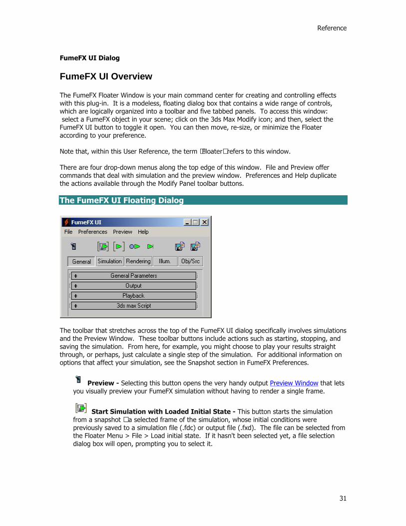
The FumeFX Floater Window is your main command center for creating and controlling effects with this plug-in. It is a modeless, floating dialog box that contains a wide range of controls, which are logically organized into a toolbar and five tabbed panels. To access this window: select a FumeFX object in your scene; click on the 3ds Max Modify icon; and then, select the FumeFX UI button to toggle it open. You can then move, re-size, or minimize the Floater according to your preference. Note that, within this User Reference, the term “Floater” refers to this window. There are four drop-down menus along the top edge of this window. File and Preview offer commands that deal with simulation and the preview window. Preferences and Help duplicate the actions available through the Modify Panel toolbar buttons. The FumeFX UI Floating Dialog
The toolbar that stretches across the top of the FumeFX UI dialog specifically involves simulations and the Preview Window. These toolbar buttons include actions such as starting, stopping, and saving the simulation. From here, for example, you might choose to play your results straight through, or perhaps, just calculate a single step of the simulation. For additional information on options that affect your simulation, see the Snapshot section in FumeFX Preferences.
Preview - Selecting this button opens the very handy output Preview Window that lets you visually preview your FumeFX simulation without having to render a single frame.
Start Simulation with Loaded Initial State - This button starts the simulation from a snapshot – a selected frame of the simulation, whose initial conditions were previously saved to a simulation file (.fdc) or output file (.fxd). The file can be selected from the Floater Menu > File > Load initial state. If it hasn't been selected yet, a file selection dialog box will open, prompting you to select it.
Printed Documentation
32
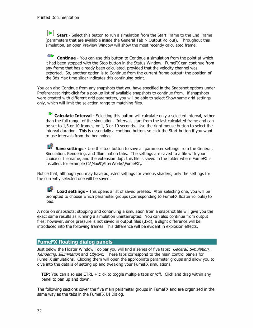
Start - Select this button to run a simulation from the Start Frame to the End Frame (parameters that are available inside the General Tab > Output Rollout). Throughout this simulation, an open Preview Window will show the most recently calculated frame.
Continue - You can use this button to Continue a simulation from the point at which it had been stopped with the Stop button in the Status Window. FumeFX can continue from any frame that has already been calculated, provided that the velocity channel was exported. So, another option is to Continue from the current frame output; the position of the 3ds Max time slider indicates this continuing point.
You can also Continue from any snapshots that you have specified in the Snapshot options under Preferences; right-click for a pop-up list of available snapshots to continue from. If snapshots were created with different grid parameters, you will be able to select Show same grid settings only, which will limit the selection range to matching files.
Calculate Interval - Selecting this button will calculate only a selected interval, rather than the full range, of the simulation. Intervals start from the last calculated frame and can be set to 1,3 or 10 frames, or 1, 3 or 10 seconds. Use the right mouse button to select the interval duration. This is essentially a continue button, so click the Start button if you want to use intervals from the beginning.
Save settings - Use this tool button to save all parameter settings from the General, Simulation, Rendering, and Illumination tabs. The settings are saved to a file with your choice of file name, and the extension .fxp; this file is saved in the folder where FumeFX is installed, for example C:\Max9\AfterWorks\FumeFX\.
Notice that, although you may have adjusted settings for various shaders, only the settings for the currently selected one will be saved.
Load settings - This opens a list of saved presets. After selecting one, you will be prompted to choose which parameter groups (corresponding to FumeFX floater rollouts) to load.
A note on snapshots: stopping and continuing a simulation from a snapshot file will give you the exact same results as running a simulation uninterrupted. You can also continue from output files; however, since pressure is not saved in output files (.fxd), a slight difference will be introduced into the following frames. This difference will be evident in explosion effects. FumeFX floating dialog panels Just below the Floater Window Toolbar you will find a series of five tabs: General, Simulation, Rendering, Illumination and Obj/Src. These tabs correspond to the main control panels for FumeFX simulations. Clicking them will open the appropriate parameter groups and allow you to dive into the details of setting up and tweaking your FumeFX simulations.
TIP: You can also use CTRL + click to toggle multiple tabs on/off. Click and drag within any panel to pan up and down.
The following sections cover the five main parameter groups in FumeFX and are organized in the same way as the tabs in the FumeFX UI Dialog.

Reference
33
General Simulation Rendering Illumination Objects/Sources
Printed Documentation
34
General
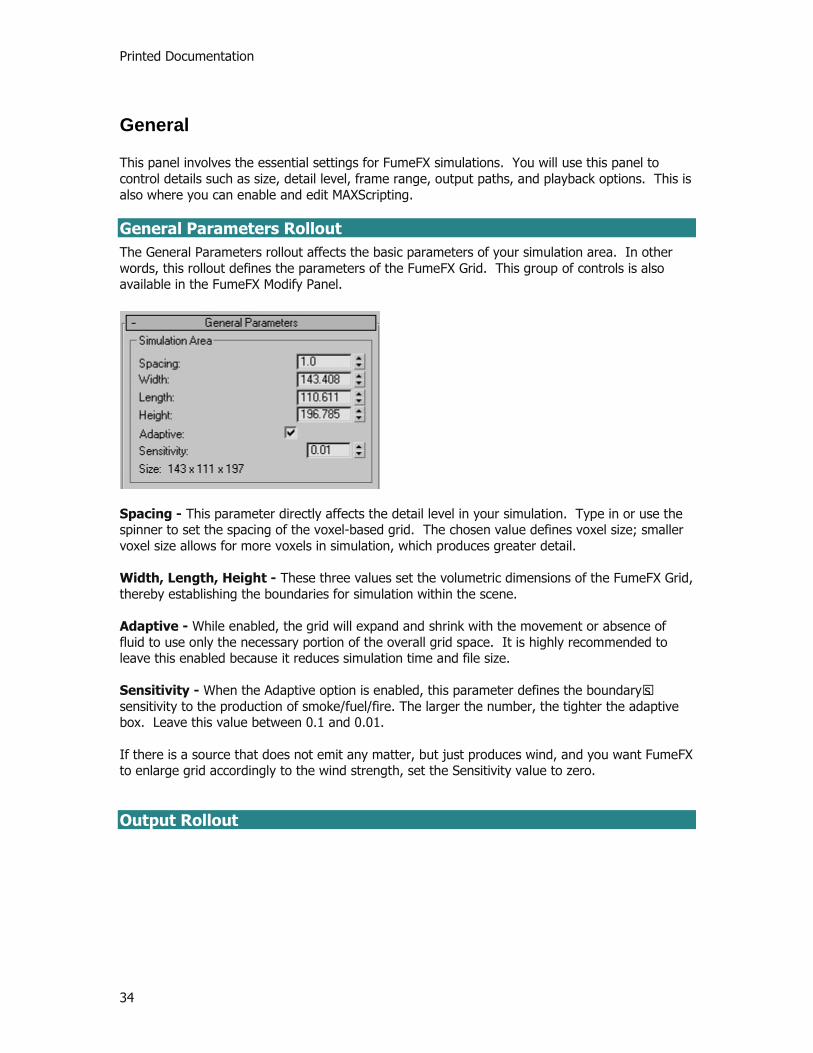
This panel involves the essential settings for FumeFX simulations. You will use this panel to control details such as size, detail level, frame range, output paths, and playback options. This is also where you can enable and edit MAXScripting. General Parameters Rollout The General Parameters rollout affects the basic parameters of your simulation area. In other words, this rollout defines the parameters of the FumeFX Grid. This group of controls is also available in the FumeFX Modify Panel.
Spacing - This parameter directly affects the detail level in your simulation. Type in or use the spinner to set the spacing of the voxel-based grid. The chosen value defines voxel size; smaller voxel size allows for more voxels in simulation, which produces greater detail. Width, Length, Height - These three values set the volumetric dimensions of the FumeFX Grid, thereby establishing the boundaries for simulation within the scene. Adaptive - While enabled, the grid will expand and shrink with the movement or absence of fluid to use only the necessary portion of the overall grid space. It is highly recommended to leave this enabled because it reduces simulation time and file size. Sensitivity - When the Adaptive option is enabled, this parameter defines the boundary’s sensitivity to the production of smoke/fuel/fire. The larger the number, the tighter the adaptive box. Leave this value between 0.1 and 0.01.
If there is a source that does not emit any matter, but just produces wind, and you want FumeFX to enlarge grid accordingly to the wind strength, set the Sensitivity value to zero. Output Rollout

Reference
35
Range Group of Controls:
Start Frame - Select the first frame of the simulation. End Frame - Select the last frame of the simulation. Viewport Update - FumeFX will display current simulation results every nth frame. If this value is 0, the viewport will not be updated during simulation. Exporting Channels - This lists the channels to be written to the output files. You can change these selections in the dialog box that is opened by the Set button.
As can be seen above, one list shows channels to be exported, and the other shows available channels that are currently excluded from export. This dialog functions much like 3ds Max's exclude dialog box; select a channel, then move it from one side of the list window to the other using the arrow buttons. Clicking on any single item will show you a short description. Channels marked with * are required for rendering with current shader and FusionWorks settings. For your reference, an updated maximum output file size is calculated (assuming that whole grid volume is used).

Printed Documentation
36
Output Path - This is the path where all outputs for the simulation will be stored (output files, snapshots, and illumination maps). This path is automatically generated when you create a FumeFX object, but it can be changed by selecting the “…” button. Playback Rollout
Playback Range Group of Controls:
Play From - This value is an output files offset. For example, if you set it to 5, the output will start playing from the 5th computed frame of the simulation (the first 4 will be skipped). Play To - This value defines output files end frame. If it is shorter than the number of all computed frames, all the remaining frames will be skipped. Any set of output frames that are clipped with Play From and Play To define a segment. Start Frame - FumeFX will not play output until 3ds Max’s frame number reaches this value. Use this to synchronize a FumeFX segment within a 3ds Max animation. Out-of-Range Types Group of Controls:
These settings define the behavior of the animation before and after the segment. Click on the button to choose from the following list of types: None - If this is chosen, no behavior information is selected. Start Frame - This holds the first frame of the segment. End Frame - This holds the last frame of the segment. Cycle - This repeats the segment. PingPong - This repeats the segment, first forward, then backward. 3ds Max Script Rollout

Reference
37
If you select the Use checkbox, you can write a script that will execute either during the simulation, or after loading the output. The Edit Script button will open the MAXScript editor. You can use MaxScripting to add forces to the simulation, or add or diminish fire or smoke, or even alter the whole simulation process. Refer to the MAXScript section of this manual for more information.

Printed Documentation
38
Simulation
As the name would indicate, this is the panel you use to regulate the parameters of your simulation. Simulation Rollout
Simulation Group of Controls
Solver - The Conjugate Gradient solver calculates the results of your simulation. For now this is the only solver that comes with FumeFX, however the architecture has been designed to incorporate other solvers as they are developed in the future. Quality - This defines simulation realism. Higher quality increases realism, but means more computation and slower simulation performance. This is sometimes necessary; for example, it is advisable to increase quality for fast moving objects. Another way to look at Quality is that this number represents how many times the the Maximum Iterations will be used to determine the simulation. Maximum Iterations - Use this to set the maximum possible amount of iterations that the solver should complete. The solver will automatically stop when it reaches an acceptable level of accuracy. The CG solver does not need many iterations to achieve good results (10-15 for small grids, 100 for bigger grids, or fast sources/objects). Simulation Steps - If the simulation becomes unstable due to very fast flows (objects, sources or forces), each frame can be divided in two or more simulation steps. Note that this will increase simulation times.

Reference
39
Advection Stride - The lower this stride is, the less dissipation of velocity and smoke will happen. It is a more or less inverse proportion to simulation time.
TIP: For smoke with many small curls you may want to decrease this number to 0.1 or less. Cubic interpolation - If you need maximum quality, you will want to check this option. Simulation times will rise considerably, but less dissipation will occur and more swirls will be created. Time Scale - Use this to speed up or slow down the passage of time during simulation. If you set it to 0, the simulation comes to a halt; set a higher value to increase speed. If you accelerate time by some significant amount (>1.5x), you will have to increase the simulation steps as well to preserve stability and continuity. Also, note that you can animate this parameter. System Group of Controls
Gravity - This value defines gravity strength. Note that this affects smoke, based on the smoke’s density value. Buoyancy - This value defines how much the fluids will rise in correspondence with the temperature. Vorticity - This parameter is very useful for coarse grids, where simulations lack detail. When you increase grid detail then the need for vorticity is lowered, since the simulation itself will result in more detail. Higher vorticity will increase the number and strength of small vortices in the fluid. Velocity Damping - This gradually slows down the speed of flow, simulating internal friction. Turbulence amounts - Add artificial disturbance to smoke and fire, as controlled by the following parameter group. X/Y/Z Turbulence - Add artificial disturbance to smoke and fire on each axis separately or on all together. The Turbulence Noise Group offers further modification. Turbulence Noise Group of Controls
Scale - Set the scale for Noise, in world units. Detail - Detail is equivalent to fractal noise levels. Set to a value greater than one if you do not see enough detail. This will, of course, slow down the simulation. Frames - This value functions as a measure of speed for each phase change. Less frames means faster turbulence. Blocking Sides Group of Controls

Printed Documentation
40
On each grid axis, you can choose to have zero, one, or two blocking sides. For example, if you set the Z-axis to "+Z" then top of the grid will act as a ceiling. If you set it back to none, the top of the grid will act as open space, letting smoke exit freely. Fuel Rollout
Select the Simulate Fuel checkbox to include it in the simulation. Then, adjust it with the following parameters: Ignition Temperature - Fuel will burn in each voxel with a temperature equal to, or greater, than this value. Burn Rate - The percentage of fuel in each voxel that is burned with each frame. Heat production and Expansion depend on the amount of burned fuel. Burn Rate Variation - This is the maximum variation allowed in the burn rate, expressed as fraction. Heat production - This determines the rate of temperature increase per burned fuel. With high heat production, temperature in the grid will increase, causing fluid to rise faster (due to the buoyancy parameter). Expansion - This determines the rate of pressure increase per burned fuel. Excessive expansion can create extreme velocities and cause simulation times to increase significantly. Fuel Creates Smoke checkbox - If you enable this option, smoke will be created on the surface of the flame; usually, it is created on the source. Smoke Density - This amount of smoke density is added to the voxel when fuel approaches zero. Smoke Rollout

Reference
41
Select the Simulate Smoke checkbox to include it in the simulation. Then, adjust it with the following parameters. Dissipation Min. Dens - If smoke density goes below this value, it will fade according to the Dissipation Strength amount. Dissipation Strength - The higher this value, the more rapidly smoke will diminish. This parameter is expressed as percentage of voxel value that will be lost. These two parameters are useful if you want to constrain smoke to a smaller volume. Restricting computations to a certain volume helps keep the adaptive grid as tight as possible, which, in turn, improves simulation speed. This may be most helpful in situations where temperature is invisible and can be clipped. Diffusion - Set the rate of smoke diffusion. Temperature Rollout
Select the Simulate Temperature checkbox to include it in the simulation. Adjust it with the following parameters, which are analogous to Smoke. FumeFX burns unreacted fuel based on Ignition Temperature; and, Temperature Diffusion is the only way to realistically spread the temperature across volume and thus, to help fire propagation. Dissipation Min. Temp - If temperature goes below this value, it will fade according to the Dissipation Strength amount. Dissipation Strength - The higher this value, the more rapidly temperature will diminish. Diffusion - This value sets the rate of temperature diffusion. At very high values, temperature inside the grid can drop dramatically. Consequently, if you are simulating burning fuel, the fuel may stop burning; if so, you might need to increase the Heat Production value.
Printed Documentation
42
Rendering
Rendering
FumeFX Rendering is controlled by the parameters in this panel of the Floater Window. For information on how to blend FumeFX results with other effects, see the FusionWorks Renderer section of this reference. Rendering Parameters Rollout
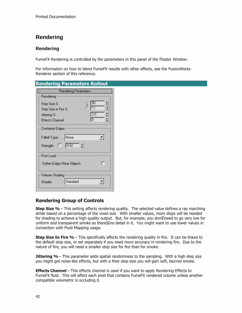
Rendering Group of Controls
Step Size % - This setting affects rendering quality. The selected value defines a ray marching stride based on a percentage of the voxel size. With smaller values, more steps will be needed for shading to achieve a high quality output. But, for example, you don’t need to go very low for uniform and transparent smoke as there’s no detail in it. You might want to use lower values in connection with Fluid Mapping usage. Step Size In Fire % - This specifically affects the rendering quality in fire. It can be linked to the default step size, or set separately if you need more accuracy in rendering fire. Due to the nature of fire, you will need a smaller step size for fire than for smoke. Jittering % - This parameter adds spatial randomness to the sampling. With a high step size you might get noise-like effects, but with a finer step size you will gain soft, blurred smoke. Effects Channel - This effects channel is used if you want to apply Rendering Effects to FumeFX fluid. This will affect each pixel that contains FumeFX rendered volume unless another compatible volumetric is occluding it.

Reference
43
Container Edges Group of Controls Falloff Type - This selection defines the method that will be used to attenuate smoke and/or fire near the edges of the simulation area. Strength - This adjusts the strength of falloff. Post Load Group of Controls Soften Edges Near Objects - By default, FumeFX assumes that all objects affecting simulation will remain visible in the rendering, so it alters the Fire and Smoke values accordingly before saving. This is intended to improve the visual output of the rendering; however, if you choose to render without those objects, this default action may make the Fire and Smoke near those objects appear coarse or aliased. In such instances, enabling this Soften Edges option will help to soften these edges. Volume Shading Group of Controls FumeFX supports specific shaders to render the visual data obtained through simulation. You can adjust the parameters of a shader to control the rendered appearance of your fiery effects. Shader - Choose an available shader from this dropdown list. Currently, FumeFX offers two choices: Standard and Channel Data. When either of these shaders is chosen, a set of rollouts specific to the shader are displayed for manipulation. To learn more on how these Volume Shaders function, click on the links below. Standard Shader Channel Data Shader
Printed Documentation
44
Standard Shader
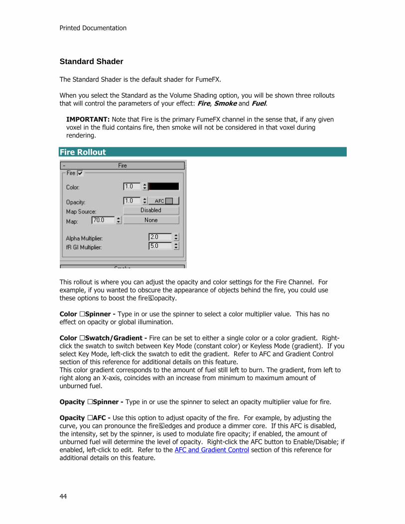
The Standard Shader is the default shader for FumeFX. When you select the Standard as the Volume Shading option, you will be shown three rollouts that will control the parameters of your effect: Fire, Smoke and Fuel.
IMPORTANT: Note that Fire is the primary FumeFX channel in the sense that, if any given voxel in the fluid contains fire, then smoke will not be considered in that voxel during rendering.
Fire Rollout
This rollout is where you can adjust the opacity and color settings for the Fire Channel. For example, if you wanted to obscure the appearance of objects behind the fire, you could use these options to boost the fire’s opacity. Color – Spinner - Type in or use the spinner to select a color multiplier value. This has no effect on opacity or global illumination. Color – Swatch/Gradient - Fire can be set to either a single color or a color gradient. Right-click the swatch to switch between Key Mode (constant color) or Keyless Mode (gradient). If you select Key Mode, left-click the swatch to edit the gradient. Refer to AFC and Gradient Control section of this reference for additional details on this feature. This color gradient corresponds to the amount of fuel still left to burn. The gradient, from left to right along an X-axis, coincides with an increase from minimum to maximum amount of unburned fuel. Opacity – Spinner - Type in or use the spinner to select an opacity multiplier value for fire. Opacity – AFC - Use this option to adjust opacity of the fire. For example, by adjusting the curve, you can pronounce the fire’s edges and produce a dimmer core. If this AFC is disabled, the intensity, set by the spinner, is used to modulate fire opacity; if enabled, the amount of unburned fuel will determine the level of opacity. Right-click the AFC button to Enable/Disable; if enabled, left-click to edit. Refer to the AFC and Gradient Control section of this reference for additional details on this feature.
Reference
45
In the AFC, the level of opacity, from left to right along an X-axis, corresponds to an increase from minimum to maximum fuel. Map Source - When there is a need for additional subtle details in the rendered output, two fluid mapping types are provided. Click this button to enable/disable Fluid Mapping, or World/Object Coordinates. Fluid Mapping is good for animations since the viewer will get an impression of small details from a procedural map following the flow. A drawback of Fluid Mapping is that it has to be computed during the simulation; consequently, it requires more memory and slows down simulation (though not significantly). The World/Object Coordinates option is excellent for still images. It requires neither computation nor memory during the simulation. Map - Click on the button to choose a map from the Material/Map Browser. Use only 3D procedural maps for texturing a fluid. Since this map will have to be evaluated at each pixel, expect slower rendering times. Alpha Multiplier - This adjusts the overall alpha channel of fire. You can use it, for example, to darken the objects behind the fire. fR GI multiplier - This option works with finalRender to adjust the fire’s global illumination intensity. Smoke Rollout
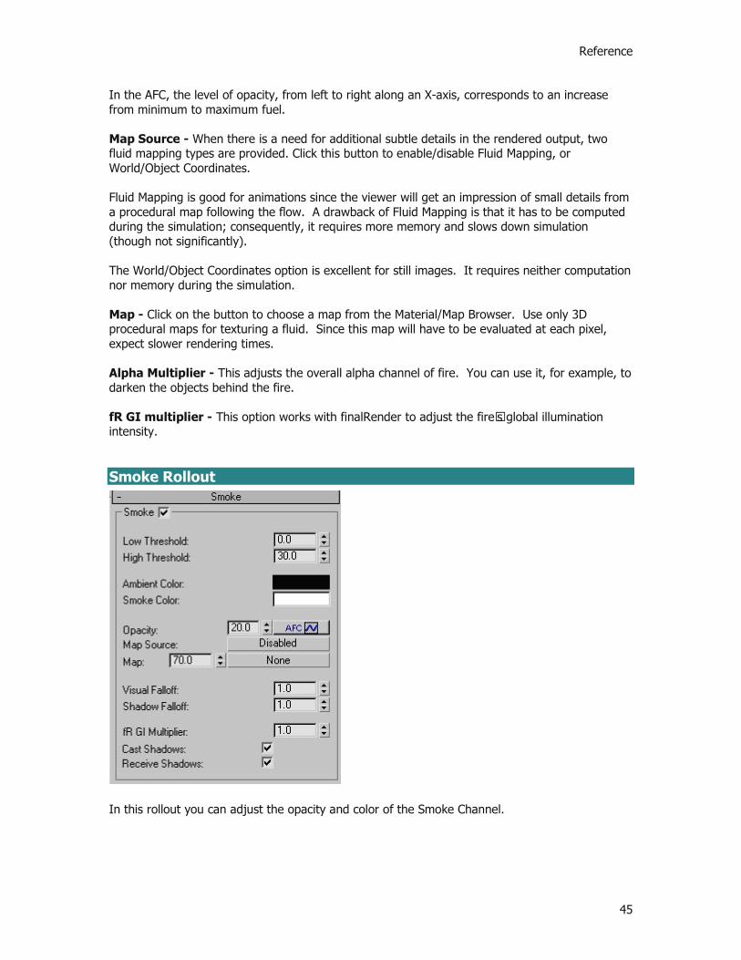
In this rollout you can adjust the opacity and color of the Smoke Channel.
Printed Documentation
46
Min. Density and Max. Density - These parameters define the limits for the Smoke Channel’s Color Gradient and Opacity AFC. If smoke density is below the Min. Density value, it will not be visible; and, if it is above Max. Density, it will have the color that corresponds to Max. Density. Color Gradient - Smoke color can be set to a solid color or to a gradient. This gradient is dependent on smoke density; i.e., a linear progression from left to right reflects a relative progression from minimum to maximum density. Right-click the swatch to switch between Key Mode (constant color) or Keyless Mode (gradient). If you select Key mode, left-click the swatch to edit the gradient. The position on the gradient depends on the level of smoke density. Refer to AFC and Gradient Control section of this reference for additional details on this feature. Ambient Color - Ambient Color in the 3ds Max Environment Panel does not affect FumeFX. Within FumeFX you can use this shader option instead. Note, though, that it only affects smoke Opacity – Spinner - This value affects the intensity of opacity that smoke will have in rendering. Use the spinner to set this value. Opacity AFC - Use this option to adjust opacity of the smoke in proportion with the amount of unburned fuel. Right-click it to Enable/Disable; left-click to edit the gradient. When Opacity AFC is disabled, the intensity of the smoke gradient is used to modulate smoke opacity. Map Source - When there is a need for additional subtle details in the rendered output, two fluid mapping types are provided. Click this button to enable/disable Fluid Mapping, or World/Object Coordinates. Fluid Mapping is good for animations since the viewer will get an impression of small details from a procedural map that follows the flow. A drawback of Fluid Mapping is that it has to be computed during the simulation; consequently, it requires more memory and slows down simulation (though not significantly). The World/Object Coordinates option is excellent for still images. It requires neither computation nor memory during the simulation. Map - Click on the button to choose a map from the Material/Map Browser. Use only 3D procedural maps for texturing a fluid. Since this map will have to be evaluated at each pixel, expect slower rendering times. Visual Falloff - This controls the rate of light drop-off inside the smoke from the camera’s view; i.e., it affects visibility into the smoke. Shadow Falloff - This controls the rate of light drop-off inside the smoke for shadows, i.e., it controls how far shadows will extend into the smoke. A higher value creates the impression of thicker smoke. fR GI multiplier - This option works with finalRender to adjust the smoke’s global illumination intensity. Cast Shadows - If on, smoke will cast shadows on the surrounding geometry and, if Receive Shadows is on, onto itself. Receive Shadows - If on, smoke will receive shadows created by surrounding geometry and, if Cast Shadows is on, from itself.

Reference
47
Fuel Rollout
Color - Fuel can only be a solid color. Opacity - Fuel opacity depends on the amount of fuel still left to burn, and is multiplied by this parameter. Visual Falloff - This value controls how far light can penetrate into fuel. fR GI multiplier - This option works with finalRender to adjust the global illumination intensity of fuel. Cast Shadows - If on, smoke will cast shadows on the surrounding geometry and, if Receive Shadows is on, onto itself. Receive Shadows - If on, smoke will receive shadows created by surrounding geometry and, if Cast Shadows is on, from itself.
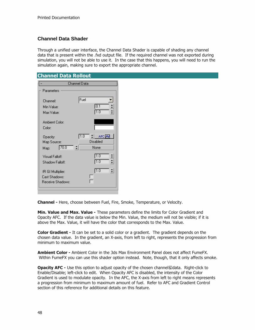
Printed Documentation
48
Channel Data Shader
Through a unified user interface, the Channel Data Shader is capable of shading any channel data that is present within the .fxd output file. If the required channel was not exported during simulation, you will not be able to use it. In the case that this happens, you will need to run the simulation again, making sure to export the appropriate channel. Channel Data Rollout
Channel - Here, choose between Fuel, Fire, Smoke, Temperature, or Velocity. Min. Value and Max. Value - These parameters define the limits for Color Gradient and Opacity AFC. If the data value is below the Min. Value, the medium will not be visible; if it is above the Max. Value, it will have the color that corresponds to the Max. Value. Color Gradient - It can be set to a solid color or a gradient. The gradient depends on the chosen data value. In the gradient, an X-axis, from left to right, represents the progression from minimum to maximum value. Ambient Color - Ambient Color in the 3ds Max Environment Panel does not affect FumeFX. Within FumeFX you can use this shader option instead. Note, though, that it only affects smoke. Opacity AFC - Use this option to adjust opacity of the chosen channel’s data. Right-click to Enable/Disable; left-click to edit. When Opacity AFC is disabled, the intensity of the Color Gradient is used to modulate opacity. In the AFC, the X-axis from left to right means represents a progression from minimum to maximum amount of fuel. Refer to AFC and Gradient Control section of this reference for additional details on this feature.

Reference
49
Map Source - When there is a need for additional subtle details in the rendered output, two fluid mapping types are provided. Click this button to enable/disable Fluid Mapping, or World/Object Coordinates. Fluid Mapping is good for animations since the viewer will get an impression of small details from a procedural map that follows the flow. A drawback of Fluid Mapping is that it has to be computed during the simulation; consequently, it requires more memory and slows down simulation (though not significantly). The World/Object Coordinates option is excellent for still images. It requires neither computation nor memory during the simulation. Map - Click on the button to choose a map from the Material/Map Browser. Use only 3D procedural maps for texturing a fluid. Since this map will have to be evaluated at each pixel, expect slower rendering times. Visual Falloff - This value controls the rate of light drop-off inside the medium. Shadow Falloff - This value controls the rate of light drop-off inside the medium for shadows. A higher value creates the impression of a thicker medium. fR GI multiplier - This option works with finalRender to adjust smoke’s global illumination intensity. Cast Shadows checkbox - If on, the medium will cast shadows onto surrounding geometry and, if Receive Shadows is on, onto itself, as well. Receive Shadows checkbox - If on, the medium will receive shadows created by surrounding geometry and, if Cast Shadows is on, from itself, as well.
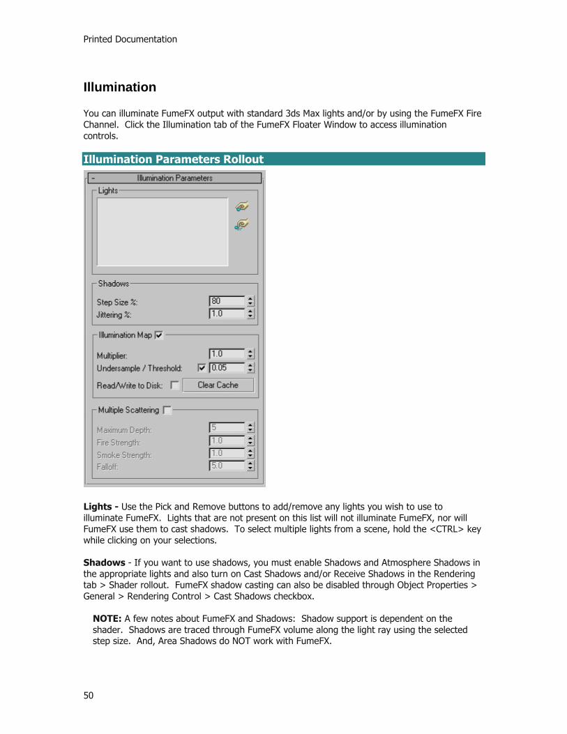
Printed Documentation
50
Illumination
You can illuminate FumeFX output with standard 3ds Max lights and/or by using the FumeFX Fire Channel. Click the Illumination tab of the FumeFX Floater Window to access illumination controls. Illumination Parameters Rollout
Lights - Use the Pick and Remove buttons to add/remove any lights you wish to use to illuminate FumeFX. Lights that are not present on this list will not illuminate FumeFX, nor will FumeFX use them to cast shadows. To select multiple lights from a scene, hold the <CTRL> key while clicking on your selections. Shadows - If you want to use shadows, you must enable Shadows and Atmosphere Shadows in the appropriate lights and also turn on Cast Shadows and/or Receive Shadows in the Rendering tab > Shader rollout. FumeFX shadow casting can also be disabled through Object Properties > General > Rendering Control > Cast Shadows checkbox.
NOTE: A few notes about FumeFX and Shadows: Shadow support is dependent on the shader. Shadows are traced through FumeFX volume along the light ray using the selected step size. And, Area Shadows do NOT work with FumeFX.

Reference
51
Step Size - This value is a percentage of voxel size. 75% is good for most uses; for transparent smoke you may use up to 300%. Less than 25% should never be needed, except when attempting an effective use of Jittering. Jittering - This value is a percentage of voxel size. It can help to reduce possible artifacts and/or soften shadows. Transparency for a volume of smoke is not taken precisely along the ray that is being traced, but rather, with a random offset whose maximum is set by this parameter. It has to be combined with small Step Size (5% - 50%) to be effective. Illumination Map Group of Controls
To accelerate rendering, FumeFX uses an illumination map, which is a per-voxel, pre-computed light map that includes shadows. It is created at rendering time, before any actual rendering takes place. A progress window will pop up if creation takes longer than a second. Caching of illumination maps to disk is an option that will accelerate subsequent renderings. Cache files are named just like simulation output files, but with the extension .fim. You invalidate a cache by deleting it or starting the simulation again. In the latter case, only the frames that have been simulated will be invalidated. Illumination Map - If you turn this checkbox off, the rendering process will be much slower. It is provided for the rare cases in which you need extreme accuracy of the shadows received by FumeFX. It does not influence shadows cast by FumeFX on other objects. Multiplier - This is a convenient way to affect all lights at once. A value of 0 creates no illumination, 2 creates twice the illumination, etc. Once the illumination map has been calculated and cached to a disk, you can tweak its intensity through this parameter without having to re-calculate. Undersample/Threshold - To speed up the illumination map calculation, you can instruct FumeFX to evaluate every 2nd voxel over each axis. This means it would only have to process 1/8 of the total number of voxels. Other voxels will only be evaluated if the difference in neighboring voxels’ illumination is greater than the Threshold parameter value. This will not reduce the illumination map file size and will have no effect if the illumination map is loaded from disk. So long as you do not notice rendering artifacts, you can set this value as high as you like. Cache Map To Disk - During rendering, the illumination map is saved to disk as illumination is pre-computed for each frame. The saved map is unaffected by the Multiplier parameter. While this option is selected, the map cache is automatically used for subsequent renderings, regardless of any changes to light settings. The only exception to this is that the cache map will not be used if the grid dimensions have been changed. This data will be saved to the folder you have selected for output and will overwrite any existing file of the same name. The Illumination Map filename is a combination of an output filename and name of the FumeFX scene object. Note that if you rename FumeFX object, cache will become unusable.
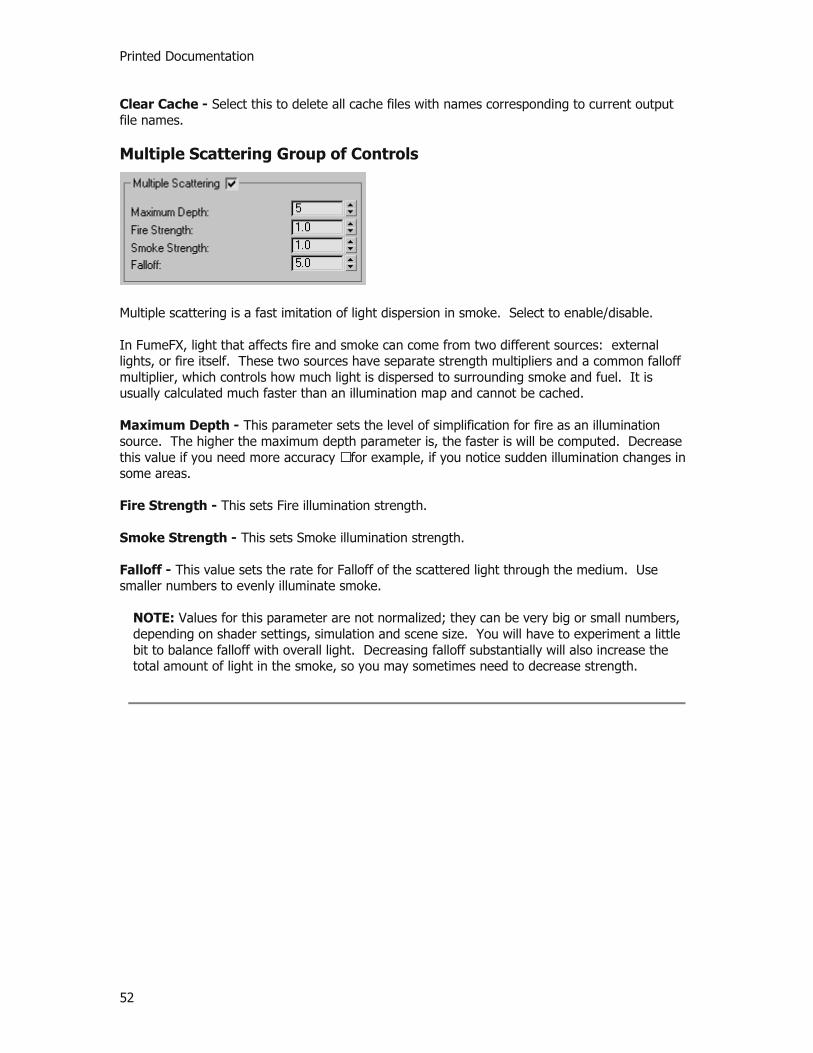
Printed Documentation
52
Clear Cache - Select this to delete all cache files with names corresponding to current output file names. Multiple Scattering Group of Controls
Multiple scattering is a fast imitation of light dispersion in smoke. Select to enable/disable. In FumeFX, light that affects fire and smoke can come from two different sources: external lights, or fire itself. These two sources have separate strength multipliers and a common falloff multiplier, which controls how much light is dispersed to surrounding smoke and fuel. It is usually calculated much faster than an illumination map and cannot be cached. Maximum Depth - This parameter sets the level of simplification for fire as an illumination source. The higher the maximum depth parameter is, the faster is will be computed. Decrease this value if you need more accuracy – for example, if you notice sudden illumination changes in some areas. Fire Strength - This sets Fire illumination strength. Smoke Strength - This sets Smoke illumination strength. Falloff - This value sets the rate for Falloff of the scattered light through the medium. Use smaller numbers to evenly illuminate smoke.
NOTE: Values for this parameter are not normalized; they can be very big or small numbers, depending on shader settings, simulation and scene size. You will have to experiment a little bit to balance falloff with overall light. Decreasing falloff substantially will also increase the total amount of light in the smoke, so you may sometimes need to decrease strength.

Reference
53
Objects, Sources and Warps
Objects, Sources and Warps
Objects, Sources, and Warps can all affect FumeFX simulations. You can access controls for all three by clicking the Obj/Src. tab in the FumeFX Floater Window. Any geometry that can be converted to mesh can be used as an object that affects FumeFX fluid. To do this, the geometry has to be picked so that its speed multiplier and volume type can be set. Then, any movement it makes through the fluid will displace the fluid. Note that there is no way that the fluid can affect the object (unless you script the object’s behavior). If the object moves too fast, the simulation may become inaccurate. It may even “eat” any smoke and fire that are on its path. These problems will be more pronounced if you have set the number of solver steps too low. To ease these problems, you can increase the number of Simulation Steps in Simulation tab. Or, if the object is just consuming smoke, you can increase the object’s Speed Multiplier, which will increase the force of its push on the fluid. Sources are explained in the section FumeFX Sources of this manual. Objects Rollout
Pick and Remove - Use these buttons to add any of the following: Objects (any geometry that can be converted to a mesh); Sources (Simple Source, Particle Source, or Object Source); or, Forces (forces that can influence Particle Systems, such as Wind or Vortex. Others like Bomb
Printed Documentation
54
and Path Follow cannot be used with FumeFX. Once selected, each is shown in the dialog with a descriptive letter to indicate if it is a Source (S), an Object (O), or a Force (W - for Warp). To remove any of the entries, simply highlight it and hit the remove icon. When you select a node within this dialog, you will be presented with an additional rollout to work with depending on the type of node you've chosen. Below is a list of the various types of rollouts you can get when adding Objects and Sources to your simulation.
Standard Object (geometry) - Object Parameters Rollout FumeFX Simple Source - Simple Source Parameters rollout FumeFX Object Source - Object Source Parameters rollout FumeFX Particle Source - Particle Source Parameters rollout Force (Gravity, Wind, Vortex, etc.) - No additional rollout FumeFX Gravity Vector - No additional rollout
NOTE: It is important to mention that the parameter controls within each of these rollouts within the FumeFX UI are identical to their gizmo counterparts. Therefore, if you select a FumeFX Source within the 3ds Max user interface and go to the Modify Panel, you will see the exact same controls in there as well, just in a different layout.

Reference
55
Object Parameters Rollout
This is a very simple dialog and is presented when the user chooses a standard piece of geometry to be used within the FumeFX simulation. In most cases, these nodes are to be used as collision objects that will block and otherwise interact with the FumeFX simulation.
Object Parameters Rollout Shell - The object has a hollow interior. Solid - The object has a filled interior. Free Flow - The object has no substance; only the Velocity Channel next to its shell will be affected. SpeedMul - The Speed Multiplier value changes the speed of an object that is used in computations. Increase this value if you want the object to push the fluid more forcefully, or decrease if you want the object to have less impact on fluid movement.

Printed Documentation
56
Simple Source Parameters Rollout
This is the basic source type, which assumes a predefined geometric shape (box, cylinder or sphere). In many cases, if you just want to create simple collision objects, it is easier to build Simple Sources into your scene rather than create real geometry and create Object Sources. To create a Simple Source, go to the Create Command Panel, and from the Helpers menu, select FumeFX -> Simple Src. Then click and drag in any 3ds Max viewport to create this Source. When done, you will be presented with a number of options. Once chosen in the FumeFX UI, the following rollout will appear. As mentioned before, it is available in both the Create/Modify Command Panel (by selecting the Simple Source gizmo), as well as here within the FumeFX UI floating dialog.
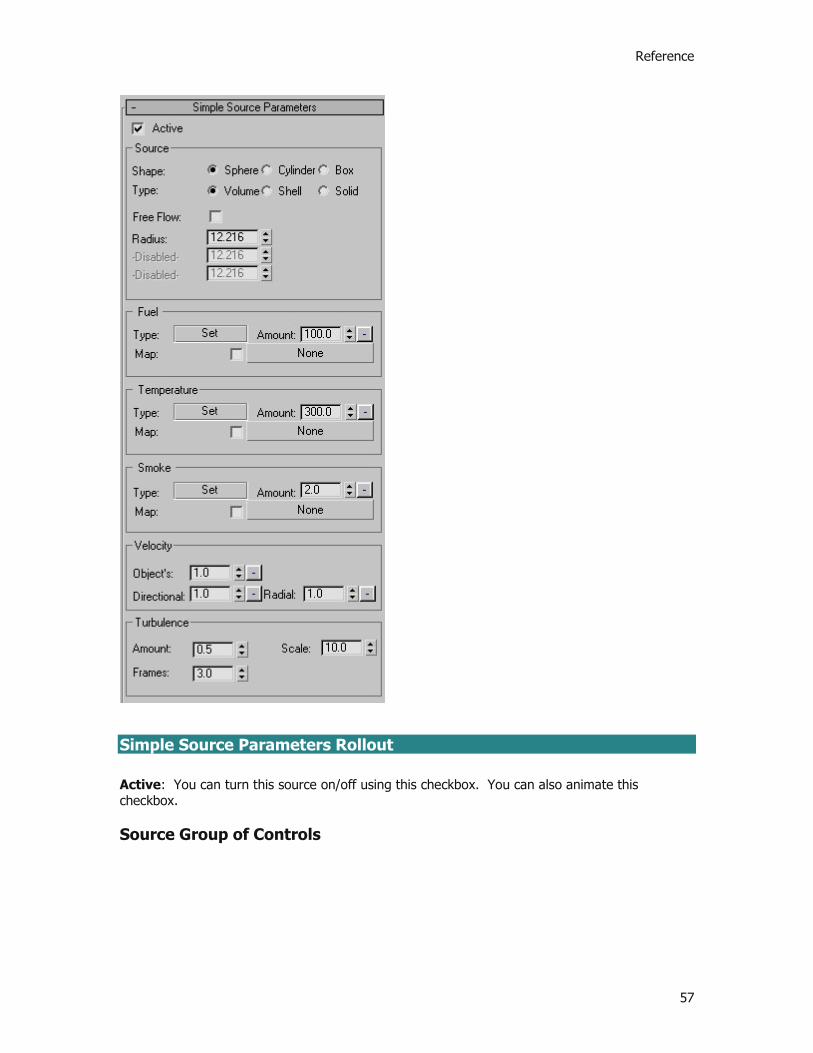
Reference
57
Simple Source Parameters Rollout Active: You can turn this source on/off using this checkbox. You can also animate this checkbox. Source Group of Controls

Printed Documentation
58
Shape - Here, choose between three basic geometries: Sphere, Cube, or Cylinder. Type - The type chosen affects how the source volume is treated:
Volume fills the entire volume of the source. Shell fills only the surface of the source. Solid fills only the surface of the source; the interior is interpreted as a solid object, so nothing can pass through it.
Free Flow checkbox - If you check this, source parameters will still influence channel values, but the source, itself, will behave just like fluid. As a result, the source’s velocity will not interrupt fluid movement in any way. Dimension Parameters - Depending on selected Shape, you can set dimensions, such as Radius, or Width, Length, and Height. Fuel, Temperature and Smoke Groups of Controls
Each of these groups has same set of parameters. These parameters work as a kind of mixing board, allowing you to balance and adjust the basic way in which different channels will affect your FumeFX simulation. Type - Click the Set button to choose the type of affect that the source will have on that channel. When you click on it, you will get the following pop-up menu:
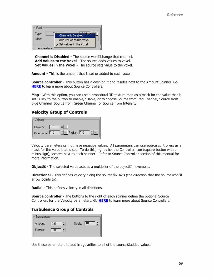
Reference
59
Channel is Disabled - The source won’t change that channel. Add Values to the Voxel - The source adds values to voxel. Set Values in the Voxel - The source sets value to the voxel.
Amount - This is the amount that is set or added to each voxel. Source controller - This button has a dash on it and resides next to the Amount Spinner. Go HERE to learn more about Source Controllers. Map - With this option, you can use a procedural 3D texture map as a mask for the value that is set. Click to the button to enable/disable, or to choose Source from Red Channel, Source from Blue Channel, Source from Green Channel, or Source from Intensity. Velocity Group of Controls
Velocity parameters cannot have negative values. All parameters can use source controllers as a mask for the value that is set. To do this, right-click the Controller icon (square button with a minus sign), located next to each spinner. Refer to Source Controller section of this manual for more information. Object’s - The selected value acts as a multiplier of the object’s movement. Directional - This defines velocity along the source’s Z-axis (the direction that the source icon’s arrow points to). Radial - This defines velocity in all directions. Source controller - The buttons to the right of each spinner define the optional Source Controllers for the Velocity parameters. Go HERE to learn more about Source Controllers. Turbulence Group of Controls
Use these parameters to add irregularities to all of the source’s added values.
Printed Documentation
60
Amount - This sets the overall amount of irregularities on a scale from 0-1. Scale - This value defines noise scale. A good initial value would be in the range of source dimensions. So, if source size is 10, then Scale should be in the range of 1 to 10. Frames - This value sets the rate of change, expressed as a number of frames for one turbulence cycle.

Reference
61
Object Source Parameters Rollout
The FumeFX Object Source lets the user build any geometry within their scene to be used as a component within their FumeFX simulation. In many cases, the objects selected within the Object Source gizmo are going to be the ignition source of the fire and smoke. Other times, they will be used to affect other fuel sources within the simulation.
NOTE: Be aware that this source type only works with geometry. You cannot select particle systems with this source type, nor can you choose forces, other helpers or non-geometry types. NURBS, Patches and Polys are all acceptable.
Once chosen in the FumeFX UI, the following rollout will appear. As mentioned before, it is available in both the Create/Modify Command Panel (by selecting the Object Source gizmo), as well as here within the FumeFX UI floating dialog.

Printed Documentation
62
Object Source Parameters Rollout Active - You can turn this source on/off using this checkbox. You can also animate this checkbox. Pick / Remove - When you create a FumeFX Object Source, the first thing you want to do is select the geometry that will become part of the simulation. Click on the Pick icon to choose an object. This basically links the geometry to the source icon, which will provide all of the parameters for the simulation.
NOTE: If you have objects that are grouped together in 3ds Max, when you use the Pick button it will select only one sub-component object from the group. It cannot operate on
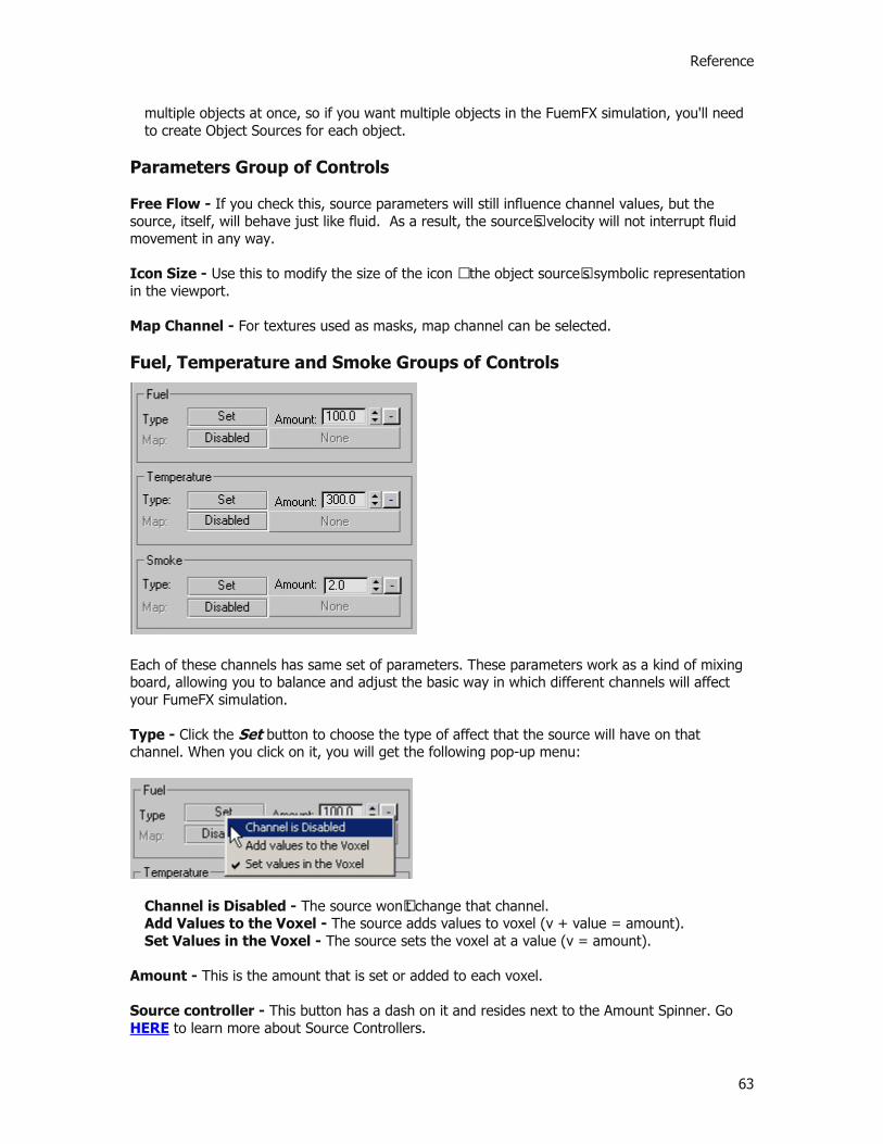
Reference
63
multiple objects at once, so if you want multiple objects in the FuemFX simulation, you'll need to create Object Sources for each object.
Parameters Group of Controls Free Flow - If you check this, source parameters will still influence channel values, but the source, itself, will behave just like fluid. As a result, the source’s velocity will not interrupt fluid movement in any way. Icon Size - Use this to modify the size of the icon – the object source’s symbolic representation in the viewport. Map Channel - For textures used as masks, map channel can be selected.
Fuel, Temperature and Smoke Groups of Controls
Each of these channels has same set of parameters. These parameters work as a kind of mixing board, allowing you to balance and adjust the basic way in which different channels will affect your FumeFX simulation. Type - Click the Set button to choose the type of affect that the source will have on that channel. When you click on it, you will get the following pop-up menu:
Channel is Disabled - The source won’t change that channel. Add Values to the Voxel - The source adds values to voxel (v + value = amount). Set Values in the Voxel - The source sets the voxel at a value (v = amount).
Amount - This is the amount that is set or added to each voxel. Source controller - This button has a dash on it and resides next to the Amount Spinner. Go HERE to learn more about Source Controllers.

Printed Documentation
64
Map - With this option, you can use a procedural 3D texture map as a mask for the value that is set. Click the Disabled button to enable/disable, or to choose Source from Red Channel, Source from Blue Channel, Source from Green Channel, or Source from Intensity as shown below. Once active, the map slot below this button will become active and ready for the user to select the map.
Velocity Group of Controls
Object’s - Use the spinner to select a multiplier value for the object’s movement. Extra - This value defines velocity in the direction of the object’s normals.
NOTE: Velocity parameters cannot have negative values. Map - With this option, you can use a procedural 3D texture map as a mask for the value that is set. Click the Disabled button to enable/disable, or to choose Source from Red Channel, Source from Blue Channel, Source from Green Channel, or Source from Intensity as shown below. Once active, the map slot below this button will become active and ready for the user to select the map.
Source controller - To the right of the Velocity spinners is a button with a dash on it. This is where you can access the Source Controller options for the velocity parameters. In this way, you can mask the values that are set. Go HERE to learn more about Source Controllers.

Reference
65
Turbulence Group of Controls
Use these parameters to add irregularities to all source added values. Amount - This sets the overall amount of irregularities on a scale from 0-1. Scale - This value defines noise scale. Frames - This value sets the speed of change per amount of Frames.
Printed Documentation
66
Particle Source Parameters Rollout
The FumeFX Particle Source lets the user create any particle system within their scene to be used as a component within their FumeFX simulation. To create a Particle Source, go to the Create Command Panel, and from the Helpers menu, select FumeFX -> Particle Src. Then click and drag in any 3ds Max viewport to create this Source. When done, you will be presented with a number of options, including which particle system to use as part of the FumeFX simulation. Additionally, AFC controllers make it possible to adjust particle parameters based on particle age.
NOTE: Be aware that this source type only works with particle systems. You cannot select geometry with this source type, nor can you choose forces, other helpers or non-geometry types. All of the built-in particle systems as well as cebas' ThinkingParticles 2 are all acceptable systems that work with FumeFX.
Once chosen in the FumeFX UI, the following rollout will appear. As mentioned before, it is available in both the Create/Modify Command Panel (by selecting the Particle Source gizmo), as well as here within the FumeFX UI floating dialog.

Reference
67
Particle Source Parameters Rollout Active - You can turn this source on/off using this checkbox.
NOTE: You can also animate this checkbox. Pick / Remove - Choose one or more particle systems that you want to use as sources within your FumeFX simulation by clicking on the Pick icon. To remove a particle system from the list, simply highlight it and hit the Remove icon.
Parameters Group of Controls
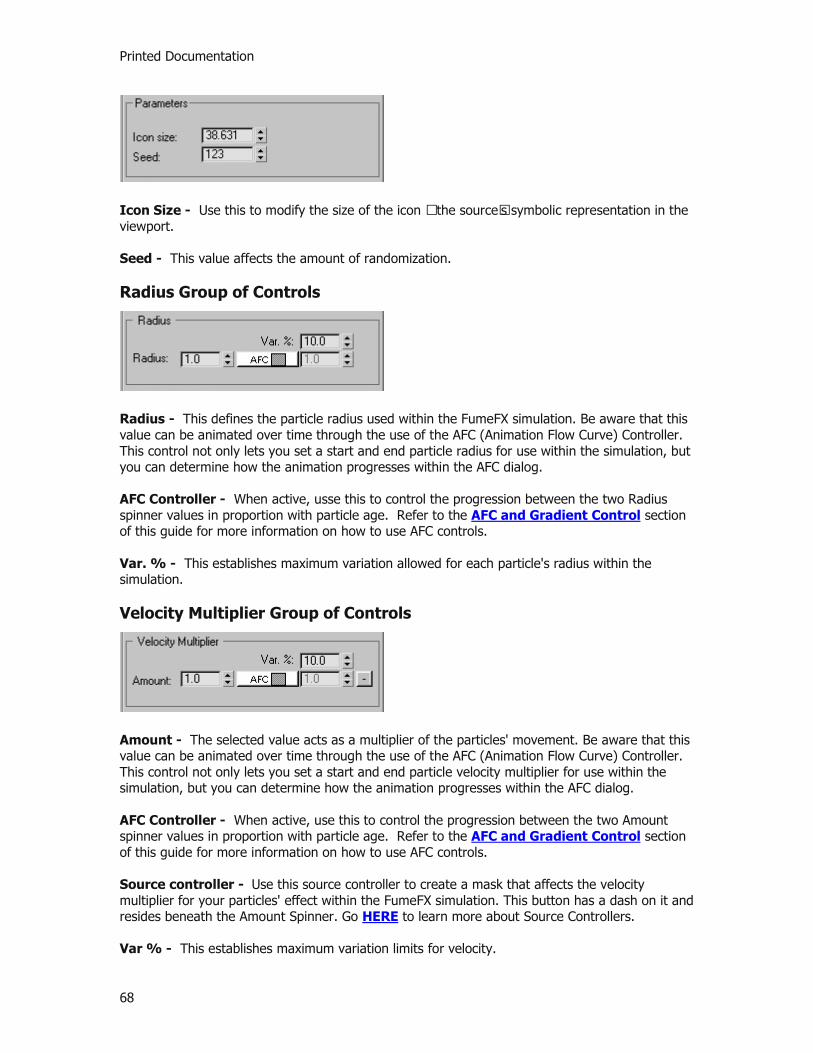
Printed Documentation
68
Icon Size - Use this to modify the size of the icon – the source’s symbolic representation in the viewport. Seed - This value affects the amount of randomization.
Radius Group of Controls
Radius - This defines the particle radius used within the FumeFX simulation. Be aware that this value can be animated over time through the use of the AFC (Animation Flow Curve) Controller. This control not only lets you set a start and end particle radius for use within the simulation, but you can determine how the animation progresses within the AFC dialog. AFC Controller - When active, usse this to control the progression between the two Radius spinner values in proportion with particle age. Refer to the AFC and Gradient Control section of this guide for more information on how to use AFC controls. Var. % - This establishes maximum variation allowed for each particle's radius within the simulation. Velocity Multiplier Group of Controls
Amount - The selected value acts as a multiplier of the particles' movement. Be aware that this value can be animated over time through the use of the AFC (Animation Flow Curve) Controller. This control not only lets you set a start and end particle velocity multiplier for use within the simulation, but you can determine how the animation progresses within the AFC dialog. AFC Controller - When active, use this to control the progression between the two Amount spinner values in proportion with particle age. Refer to the AFC and Gradient Control section of this guide for more information on how to use AFC controls. Source controller - Use this source controller to create a mask that affects the velocity multiplier for your particles' effect within the FumeFX simulation. This button has a dash on it and resides beneath the Amount Spinner. Go HERE to learn more about Source Controllers. Var % - This establishes maximum variation limits for velocity.

Reference
69
Fuel, Temperature and Smoke Groups of Controls
Each of these channels has same set of parameters. These parameters work as a kind of mixing board, allowing you to set the values of the Fuel, Smoke and Temperature Channels in your source. One notable feature of Particle Sources is that you can use an AFC (Animated Flow Curve) as a mask. For each AFC, the X-axis represents a progression of particle age, while the Y-axis represents the amount of masking that is taking place. Type - Click the Add button to choose the type of affect that the source will have on that channel. When you click on it, you will get the following pop-up menu:
Channel is Disabled - The source won’t change that channel. Add Values to the Voxel - The source adds values to voxel (v + value = amount). Set Values in the Voxel - The source sets the voxel at a value (v = amount).
Amount - This is the amount that is set or added to each voxel. Be aware that this value can be animated over time through the use of the AFC (Animation Flow Curve) Controller. This control not only lets you set a start and end particle velocity multiplier for use within the simulation, but you can determine how the animation progresses within the AFC dialog. AFC Controller - Use this to control the channel’s progression in proportion with particle age. Refer to the AFC and Gradient Control section of this reference for more information. Source controller - Use this source controller to create masks that affects the various aspects of your particles' effect within the FumeFX simulation. This button has a dash on it and resides beneath the Amount Spinner. Go HERE to learn more about Source Controllers.

Printed Documentation
70
FumeFX Sources
Source Basics
Smoke and fire effects have to be created somehow and come from somewhere. This is where FumeFX Sources come into play. A source is a helper object that serves as a point of origin. This is where your simulation and all of its essential characteristics stem from. To create a FumeFX Source, go to the 3ds Max Create tab > Helpers category and select FumeFX from the drop-down list. An Object Type Rollout will appear, prompting you to choose from Simple Src, Object Src, Particle Src or GravityVector (each source type is explained further in the following sections). Select the type of source you want and then click in a viewport to create the source. Each source appears in your scene as an icon, which you can move, re-name, or re-size. Depending on the Source type, the icon can function as the actual source, or be linked to a particle system or object that will act as the source.
Sources have equivalent user interfaces in both the 3ds Max Create panel and the FumeFX UI floating dialog. Within the 3ds Max Create and Modify Command Panels, you can adjust the source’s parameters in order to control the basic output of the Fire, Smoke, Temperature or Velocity Channels. Any item that you have chosen to use as a source will take on these parameters. Sources operate on a per-voxel basis; so, every voxel that the source touches is defined by the parameters of the source. Source parameters can also be set to negative values. Negative values will not propagate through the grid like normal smoke or fire; they can only take effect in the volume that the source itself occupies. Negative values in the Fuel Channel will extinguish fuel or fire, whichever is in the affected voxel.
IMPORTANT: Be aware that the FumeFX simulation treats the source differently than the fluid surrounding it. This may not always be what you want. For example, if you want the source to add smoke into the system, but not to affect the fluid velocity in any way, you must check the Free Flow option so that it simply creates smoke without affecting the other aspects of your simulation.
Simple Sources FumeFX Object Sources

Reference
71
FumeFX Particle Sources
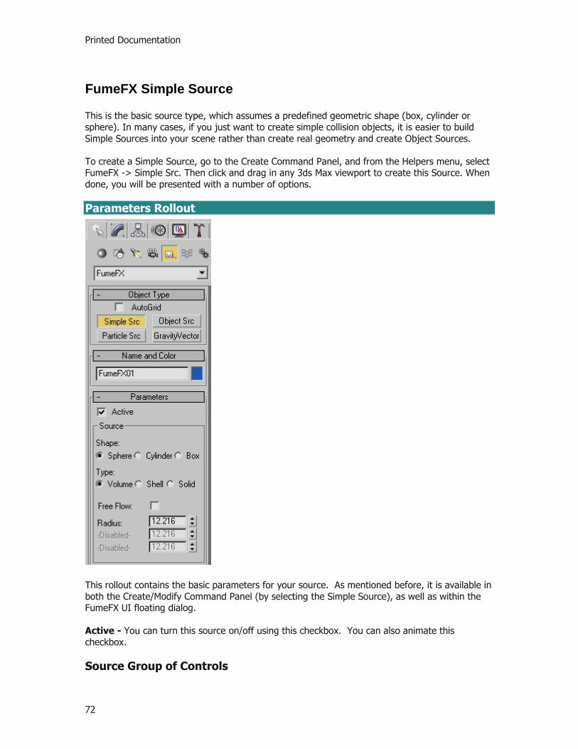
Printed Documentation
72
FumeFX Simple Source
This is the basic source type, which assumes a predefined geometric shape (box, cylinder or sphere). In many cases, if you just want to create simple collision objects, it is easier to build Simple Sources into your scene rather than create real geometry and create Object Sources. To create a Simple Source, go to the Create Command Panel, and from the Helpers menu, select FumeFX -> Simple Src. Then click and drag in any 3ds Max viewport to create this Source. When done, you will be presented with a number of options. Parameters Rollout
This rollout contains the basic parameters for your source. As mentioned before, it is available in both the Create/Modify Command Panel (by selecting the Simple Source), as well as within the FumeFX UI floating dialog. Active - You can turn this source on/off using this checkbox. You can also animate this checkbox. Source Group of Controls

Reference
73
Shape - Here, choose between three basic geometries: Sphere, Cube, or Cylinder. Type - The type chosen affects how the source volume is treated:
Volume fills the entire volume of the source. Shell fills only the surface of the source. Solid fills only the surface of the source; the interior is interpreted as a solid object, so nothing can pass through it.
Free Flow checkbox - If you check this, source parameters will still influence channel values, but the source, itself, will behave just like fluid. As a result, the source’s velocity will not interrupt fluid movement in any way. Dimension Parameters - Depending on selected Shape, you can set dimensions, such as Radius, or Width, Length, and Height. Fuel, Temperature and Smoke Groups of Controls
Each of these groups has same set of parameters. These parameters work as a kind of mixing board, allowing you to balance and adjust the basic way in which different channels will affect your FumeFX simulation. Type - Click the Set button to choose the type of affect that the source will have on that channel. When you click on it, you will get the following pop-up menu:
Channel is Disabled - The source won’t change that channel. Add Values to the Voxel - The source adds values to voxel. Set Values in the Voxel - The source sets value to the voxel.

Printed Documentation
74
Amount - This is the amount that is set or added to each voxel. Source controller - This button has a dash on it and resides next to the Amount Spinner. Go HERE to learn more about Source Controllers. Map - With this option, you can use a procedural 3D texture map as a mask for the value that is set. Click to the button to enable/disable, or to choose Source from Red Channel, Source from Blue Channel, Source from Green Channel, or Source from Intensity. Turbulence Group of Controls
Use these parameters to add irregularities to all of the source’s added values. Amount - This sets the overall amount of irregularities on a scale from 0-1. Scale - This value defines noise scale. A good initial value would be in the range of source dimensions. So, if source size is 10, then Scale should be in the range of 1 to 10. Frames - This value sets the rate of change, expressed as a number of frames for one turbulence cycle. Velocity Group of Controls
Velocity parameters cannot have negative values. All parameters can use source controllers as a mask for the value that is set. To do this, right-click the Controller icon (square button with a minus sign), located next to each spinner. Refer to Source Controller section of this manual for more information. Object’s - The selected value acts as a multiplier of the object’s movement. Directional - This defines velocity along the source’s Z-axis (the direction that the source icon’s arrow points to). Radial - This defines velocity in all directions. Source controller - To the right of the Velocity spinners is a button with a dash on it. This is where you can access the Source Controller options for the velocity parameters. Go HERE to learn more about Source Controllers.

Reference
75

Printed Documentation
76
FumeFX Object Source
The FumeFX Object Source lets the user build any geometry within their scene to be used as a component within their FumeFX simulation. In many cases, the objects selected within the Object Source gizmo are going to be the ignition source of the fire and smoke. Other times, they will be used to affect other fuel sources within the simulation. To create an Object Source, go to the Create Command Panel, and from the Helpers menu, select FumeFX -> Object Src. Then click and drag in any 3ds Max viewport to create this Source. When done, you will be presented with a number of options, including which geometric object to use as part of the FumeFX simulation.
NOTE: Be aware that this source type only works with geometry. You cannot select particle systems with this source type, nor can you choose forces, other helpers or non-geometry types. NURBS, Patches and Polys are all acceptable.
Parameters Rollout
This rollout contains the basic parameters for your object source. As mentioned before, all of its controls are available in both the Create/Modify Command Panel (by selecting the Object Source gizmo), as well as within the FumeFX UI floating dialog.
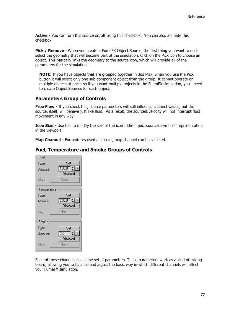
Reference
77
Active - You can turn this source on/off using this checkbox. You can also animate this checkbox. Pick / Remove - When you create a FumeFX Object Source, the first thing you want to do is select the geometry that will become part of the simulation. Click on the Pick icon to choose an object. This basically links the geometry to the source icon, which will provide all of the parameters for the simulation.
NOTE: If you have objects that are grouped together in 3ds Max, when you use the Pick button it will select only one sub-component object from the group. It cannot operate on multiple objects at once, so if you want multiple objects in the FuemFX simulation, you'll need to create Object Sources for each object.
Parameters Group of Controls
Free Flow - If you check this, source parameters will still influence channel values, but the source, itself, will behave just like fluid. As a result, the source’s velocity will not interrupt fluid movement in any way. Icon Size - Use this to modify the size of the icon – the object source’s symbolic representation in the viewport. Map Channel - For textures used as masks, map channel can be selected.
Fuel, Temperature and Smoke Groups of Controls
Each of these channels has same set of parameters. These parameters work as a kind of mixing board, allowing you to balance and adjust the basic way in which different channels will affect your FumeFX simulation.

Printed Documentation
78
Type - Click the Set button to choose the type of affect that the source will have on that channel. When you click on it, you will get the following pop-up menu:
Channel is Disabled - The source won’t change that channel. Add Values to the Voxel - The source adds values to voxel (v + value = amount). Set Values in the Voxel - The source sets the voxel at a value (v = amount).
Amount - This is the amount that is set or added to each voxel. Source controller - This button has a dash on it and resides next to the Amount Spinner. Go HERE to learn more about Source Controllers. Map - With this option, you can use a procedural 3D texture map as a mask for the value that is set. Click the Disabled button to enable/disable, or to choose Source from Red Channel, Source from Blue Channel, Source from Green Channel, or Source from Intensity as shown below. Once active, the map slot below this button will become active and ready for the user to select the map.
Velocity Group of Controls
Object’s - Use the spinner to select a multiplier value for the object’s movement. Extra - This value defines velocity in the direction of the object’s normals.
NOTE: Velocity parameters cannot have negative values.
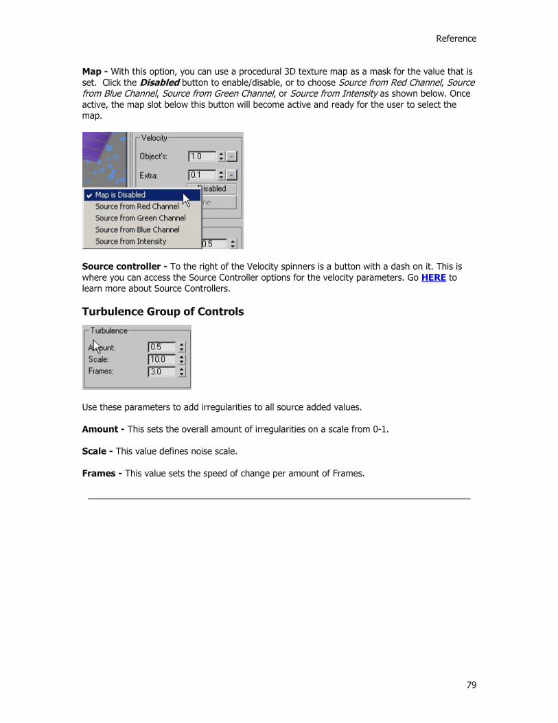
Reference
79
Map - With this option, you can use a procedural 3D texture map as a mask for the value that is set. Click the Disabled button to enable/disable, or to choose Source from Red Channel, Source from Blue Channel, Source from Green Channel, or Source from Intensity as shown below. Once active, the map slot below this button will become active and ready for the user to select the map.
Source controller - To the right of the Velocity spinners is a button with a dash on it. This is where you can access the Source Controller options for the velocity parameters. Go HERE to learn more about Source Controllers. Turbulence Group of Controls
Use these parameters to add irregularities to all source added values. Amount - This sets the overall amount of irregularities on a scale from 0-1. Scale - This value defines noise scale. Frames - This value sets the speed of change per amount of Frames.

Printed Documentation
80
FumeFX Particle Source
The FumeFX Particle Source lets the user create any particle system within their scene to be used as a component within their FumeFX simulation. To create a Particle Source, go to the Create Command Panel, and from the Helpers menu, select FumeFX -> Particle Src. Then click and drag in any 3ds Max viewport to create this Source. When done, you will be presented with a number of options, including which particle system to use as part of the FumeFX simulation. Additionally, AFC controllers make it possible to adjust particle parameters based on particle age.
NOTE: Be aware that this source type only works with particle systems. You cannot select geometry with this source type, nor can you choose forces, other helpers or non-geometry types. All of the built-in particle systems as well as cebas' ThinkingParticles 2 are all acceptable systems that work with FumeFX.
Parameters Rollout
This rollout contains the basic parameters for your particle source. As mentioned before, all of its controls are available in both the Create/Modify Command Panel (by selecting the Particle Source gizmo), as well as within the FumeFX UI floating dialog.
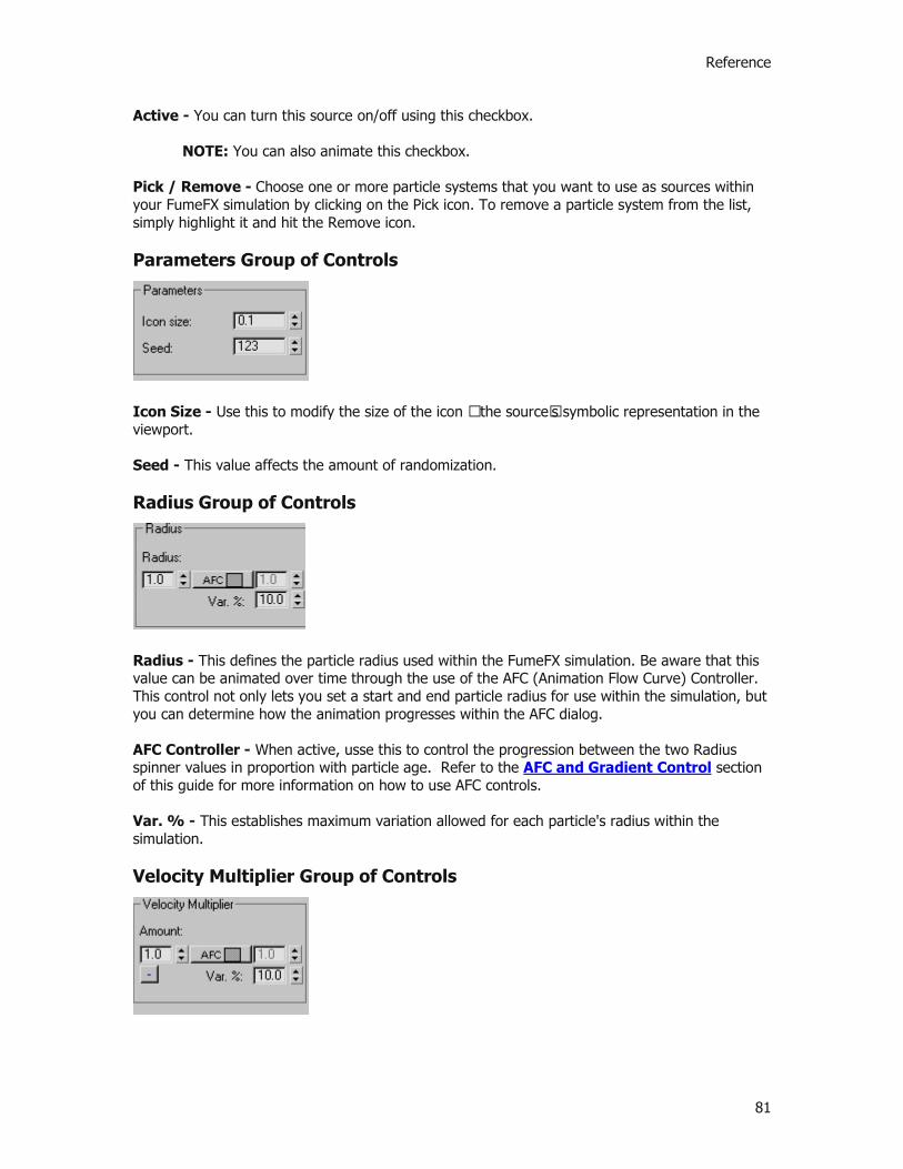
Reference
81
Active - You can turn this source on/off using this checkbox.
NOTE: You can also animate this checkbox. Pick / Remove - Choose one or more particle systems that you want to use as sources within your FumeFX simulation by clicking on the Pick icon. To remove a particle system from the list, simply highlight it and hit the Remove icon.
Parameters Group of Controls
Icon Size - Use this to modify the size of the icon – the source’s symbolic representation in the viewport. Seed - This value affects the amount of randomization.
Radius Group of Controls
Radius - This defines the particle radius used within the FumeFX simulation. Be aware that this value can be animated over time through the use of the AFC (Animation Flow Curve) Controller. This control not only lets you set a start and end particle radius for use within the simulation, but you can determine how the animation progresses within the AFC dialog. AFC Controller - When active, usse this to control the progression between the two Radius spinner values in proportion with particle age. Refer to the AFC and Gradient Control section of this guide for more information on how to use AFC controls. Var. % - This establishes maximum variation allowed for each particle's radius within the simulation. Velocity Multiplier Group of Controls
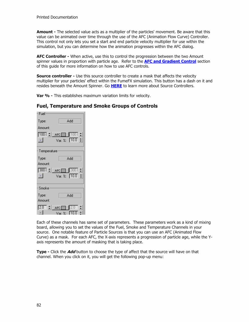
Printed Documentation
82
Amount - The selected value acts as a multiplier of the particles' movement. Be aware that this value can be animated over time through the use of the AFC (Animation Flow Curve) Controller. This control not only lets you set a start and end particle velocity multiplier for use within the simulation, but you can determine how the animation progresses within the AFC dialog. AFC Controller - When active, use this to control the progression between the two Amount spinner values in proportion with particle age. Refer to the AFC and Gradient Control section of this guide for more information on how to use AFC controls. Source controller - Use this source controller to create a mask that affects the velocity multiplier for your particles' effect within the FumeFX simulation. This button has a dash on it and resides beneath the Amount Spinner. Go HERE to learn more about Source Controllers. Var % - This establishes maximum variation limits for velocity.
Fuel, Temperature and Smoke Groups of Controls
Each of these channels has same set of parameters. These parameters work as a kind of mixing board, allowing you to set the values of the Fuel, Smoke and Temperature Channels in your source. One notable feature of Particle Sources is that you can use an AFC (Animated Flow Curve) as a mask. For each AFC, the X-axis represents a progression of particle age, while the Y-axis represents the amount of masking that is taking place. Type - Click the Add button to choose the type of affect that the source will have on that channel. When you click on it, you will get the following pop-up menu:
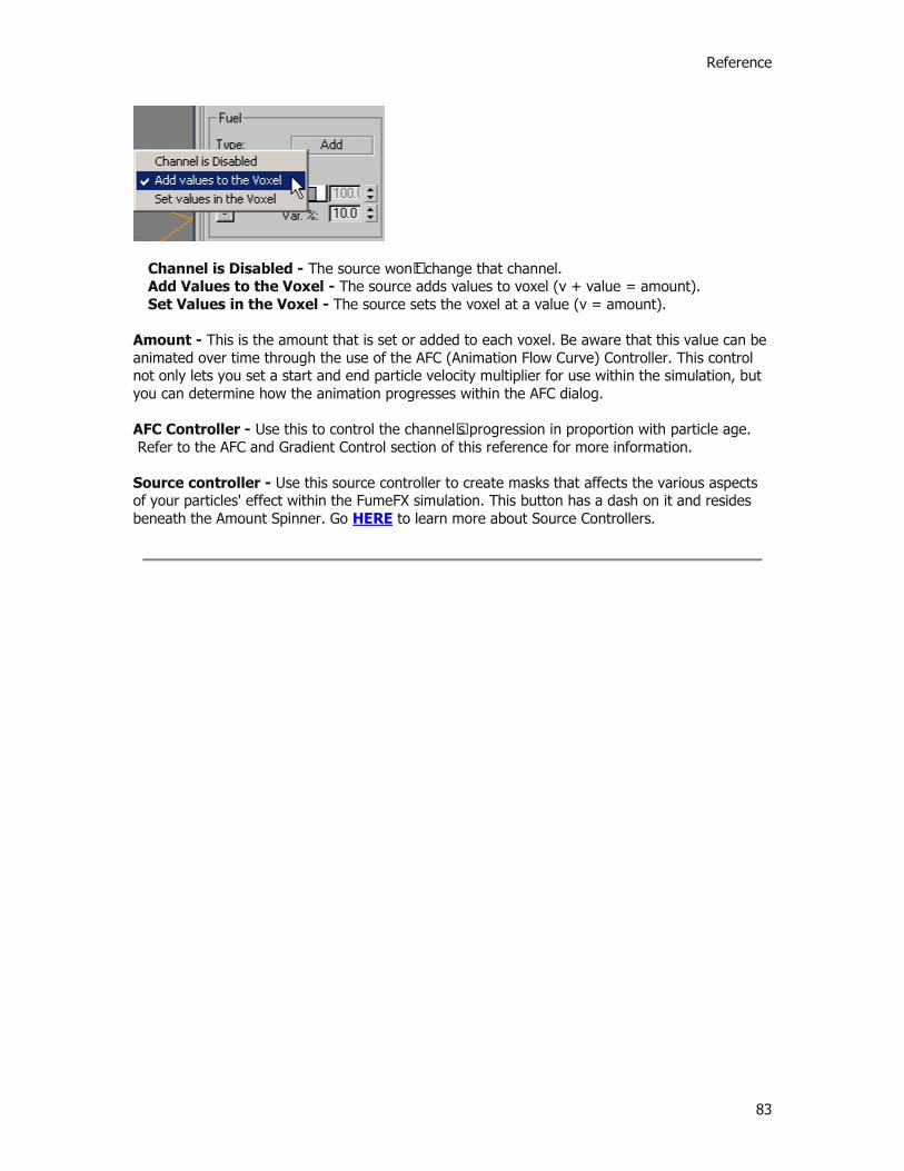
Reference
83
Channel is Disabled - The source won’t change that channel. Add Values to the Voxel - The source adds values to voxel (v + value = amount). Set Values in the Voxel - The source sets the voxel at a value (v = amount).
Amount - This is the amount that is set or added to each voxel. Be aware that this value can be animated over time through the use of the AFC (Animation Flow Curve) Controller. This control not only lets you set a start and end particle velocity multiplier for use within the simulation, but you can determine how the animation progresses within the AFC dialog. AFC Controller - Use this to control the channel’s progression in proportion with particle age. Refer to the AFC and Gradient Control section of this reference for more information. Source controller - Use this source controller to create masks that affects the various aspects of your particles' effect within the FumeFX simulation. This button has a dash on it and resides beneath the Amount Spinner. Go HERE to learn more about Source Controllers.
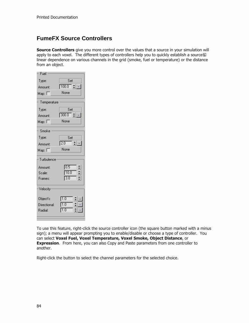
Printed Documentation
84
FumeFX Source Controllers
Source Controllers give you more control over the values that a source in your simulation will apply to each voxel. The different types of controllers help you to quickly establish a source’s linear dependence on various channels in the grid (smoke, fuel or temperature) or the distance from an object.
To use this feature, right-click the source controller icon (the square button marked with a minus sign); a menu will appear prompting you to enable/disable or choose a type of controller. You can select Voxel Fuel, Voxel Temperature, Voxel Smoke, Object Distance, or Expression. From here, you can also Copy and Paste parameters from one controller to another. Right-click the button to select the channel parameters for the selected choice.
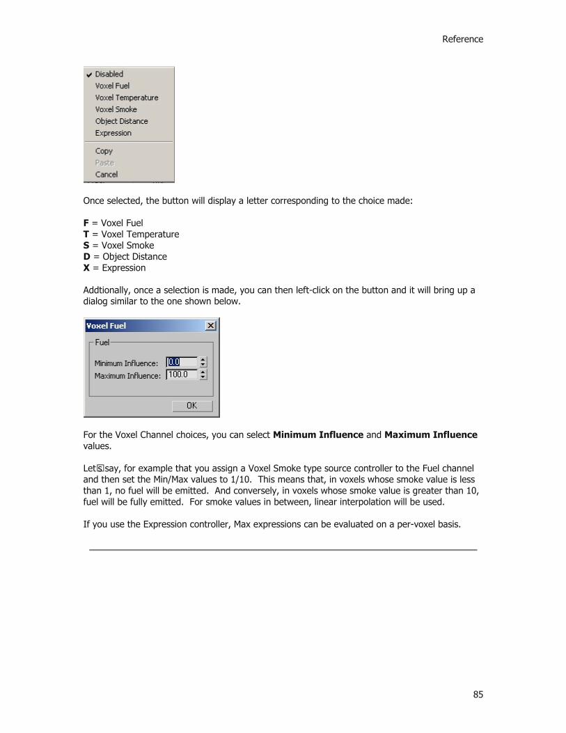
Reference
85
Once selected, the button will display a letter corresponding to the choice made: F = Voxel Fuel T = Voxel Temperature S = Voxel Smoke D = Object Distance X = Expression Addtionally, once a selection is made, you can then left-click on the button and it will bring up a dialog similar to the one shown below.
For the Voxel Channel choices, you can select Minimum Influence and Maximum Influence values. Let’s say, for example that you assign a Voxel Smoke type source controller to the Fuel channel and then set the Min/Max values to 1/10. This means that, in voxels whose smoke value is less than 1, no fuel will be emitted. And conversely, in voxels whose smoke value is greater than 10, fuel will be fully emitted. For smoke values in between, linear interpolation will be used. If you use the Expression controller, Max expressions can be evaluated on a per-voxel basis.

Printed Documentation
86
FumeFX Output Preview Window
Preview Window
FumeFX’s Output Preview Window is an incredibly helpful and timesaving part of the interface. It is an interactive window that displays a high quality draft of your simulation results; this means that you can gauge the affect of your adjustments without having to repeatedly stop and render. Key features of the Preview Window are its scalable dimensions, interactive auto-refresh, and channel display. You can open the Preview Window at any time from the Preview icons in either the FumeFX UI floating dialog, the Modify Panel (with the FumeFX Grid selected) or Status window (shown below).. Once opened, you can position the window anywhere on the screen, and scale its size by clicking and dragging on any corner.
When you begin any simulation preview, a secondary window, the FumeFX Dynamics Status Window, will open, as shown below.

Reference
87
This window displays current statistics, such as RAM usage, estimated time to completion, and frame-by-frame simulation information. You can use the control buttons on this window to Stop, or Pause and Resume a simulation as well as launch the Preview Window from any point during the simulation. This window will automatically close when you stop the simulation unless you select the Hold open checkbox. If you press Cancel, no data will be saved and you will not be able to continue simulation from that point.
NOTE: If you open the Preview Window during simulation you may have to wait until the current frame is calculated for the window to refresh.

Printed Documentation
88
Gravity Vectors
Gravity Vectors
Gravity Vectors are FumeFX helper objects, but function differently than previously mentioned Sources. You can attach one of these helpers to FumeFX grid in order to direct gravitational (and buoyant) forces in a direction other then global Z-axis. There are no parameters for this helper; it simply takes effect if, when and where it is attached.

Reference
89
FumeFX Particle Flow Operators
FumeFX Particle Flow Operators
One of the many options that you have with FumeFX is that you can use a Particle System as the source of your simulations (as explained in the FumeFX Particle Source section of this reference). Particle Flow operators offer a way to control any such particle system over the course of its life. Although Particle Flow is an element of 3ds Max, FumeFX comes with operators that allow you to employ several of its features. These operators are: FumeFX Birth, FumeFX Follow, and FumeFX Test. It is highly recommended that you use the Cache operator that comes with Particle Flow; this will help you to avoid any delays caused when PF has to re-compute the particle positions. For example, if you move the time slider one frame backwards without using the Cache operator, PF would have to update the particles starting from the Birth Event’s start time. Furthermore, FumeFX would have to load its output for each frame, as well. FumeFX can immediately affect Particle Flow during simulation, which allows you to track progress in viewport. The most significant feature is that, through the use of Particle Sources, FumeFX and Particle Flow can dynamically affect each other during simulation! After the simulation is complete, particles can be cached to produce the same behavior as they did during FumeFX simulation. The majority of your Particle Flow options are located in the Preview Window. In order to access this, you first need to create a Particle System. Then, while the Particle emitter icon is selected, click on the Particle View button that appears in the 3ds Max control panel. In the Depot pane of this window, select FumeFX to access the appropriate controls. FumeFX Test This operator selects particles that match one or all of the conditions that you have set on a per-channel basis. These conditions refer to the fluid properties of a selected FumeFX object at a given particle position. To use this: select the channels that you want to test; set the span of values that will be considered a match for that channel (or invert if you want to select values outside of that span); and, relax the test area with the Variation parameter. Then, choose whether you would like all or just a certain condition(s) to be met. As with many Particle Flow operators and tests, you can choose to interpret parameter keying in 3ds Max time, particle age, or event duration.
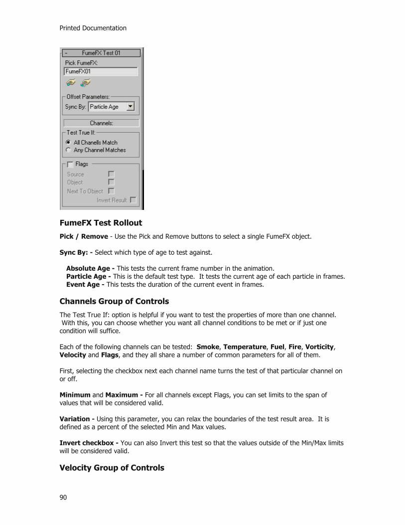
Printed Documentation
90
FumeFX Test Rollout
Pick / Remove - Use the Pick and Remove buttons to select a single FumeFX object.
Sync By: - Select which type of age to test against.
Absolute Age - This tests the current frame number in the animation. Particle Age - This is the default test type. It tests the current age of each particle in frames. Event Age - This tests the duration of the current event in frames.
Channels Group of Controls
The Test True If: option is helpful if you want to test the properties of more than one channel. With this, you can choose whether you want all channel conditions to be met or if just one condition will suffice. Each of the following channels can be tested: Smoke, Temperature, Fuel, Fire, Vorticity, Velocity and Flags, and they all share a number of common parameters for all of them. First, selecting the checkbox next each channel name turns the test of that particular channel on or off.
Minimum and Maximum - For all channels except Flags, you can set limits to the span of values that will be considered valid. Variation - Using this parameter, you can relax the boundaries of the test result area. It is defined as a percent of the selected Min and Max values. Invert checkbox - You can also Invert this test so that the values outside of the Min/Max limits will be considered valid. Velocity Group of Controls

Reference
91
The Velocity group has an additional option that lets you select which particular component of velocity will be tested. Select from the dropdown list. Planes and axes are local to the FumeFX object. Units are defined as world units per frame. Also, you cannot differentiate the positive or negative direction.
If you select Velocity X, Y or Z, the test will only check the velocity component that is situated across the selected axis. If you select Velocity XY, YZ or XZ, the test will apply to the velocity component across the selected plane. If you select Velocity Magnitude, the overall velocity will be tested.
Vorticity Defined
Vorticity is a virtual channel, dependent on the Velocity channel – similar to the way in which Fire is stored in the Fuel channel. Vorticity is calculated from the velocities of nearby voxels. Accordingly, this test will have no effect if the FumeFX output doesn't contain the Velocity channel. Vorticity refers to the small vortices, or curls in the fluid. So, with PF, you can test for particles in areas where smoke is curled. The amounts for the Vorticity channel depend on the velocities in the grid and the type of scene units; so the Min. and Max. values that you choose are highly dependent on the specifics of your scene/simulation. Experiment to find appropriate values. Flags Defined
The Flags channel is used to mark the presence of objects or sources in the fluid. This is not a test of all current scene objects and FumeFX Sources; rather, it only tests for objects that were used during FumeFX simulation. Even if these objects and sources have been deleted or moved or removed, their information remains stored in the Flags channel. You can use this channel to test for the following:
Source - This tests whether a FumeFX Source occupies a certain voxel. Object - This tests whether an object occupies a certain voxel. Next to Object - This tests whether a neighboring voxel is occupied by an object.
FumeFX Birth Operator FumeFX Birth is derived from a FumeFX PF Fluid Test. This operator enables you to create particles in only those areas of the fluid that you have selected through per-channel conditions.

Printed Documentation
92
Creation Group of Controls
Emit Start and Emit Stop - Select frame numbers to schedule the action of your particles. Rate - This determines how many particles per second will be created. By Volume checkbox - If selected, the amount of particles created will depend on the size of the area where they can appear in proportion to the entire FumeFX Object volume. So, if you set this value to 1% of the Birth Rate parameter, then particles will only appear in 1% of the total volume. If it seems that a disproportionately small number of particles are being created, you probably need to increase the birth rate. Jitter % - Use bigger values to relax test results area. For example, if this is set to 0, particles will appear only in center of each affected voxel. Conversely, if you raise this to 50%, particles will appear randomly within a voxel. Inherit From FumeFX Group of Controls
Created particles inherit their initial speed and orientation from the FumeFX fluid. You can tweak those attributes through the following two parameters. Speed Multiplier - At the default value of 1, particles will maintain the exact speed of the FumeFX fluid. At 0, the particles will have no speed at all. Also, since negative values are supported, you can make particles move in opposition to the FumeFX fluid. Speed Variation - This value represents a percentage of the fluid speed.
Channels Group of Controls
All parameters in the Channel group are identical to those of the Fluid Test; refer to the FumeFX Test section of this reference for more information.

Reference
93
Subframe Sampling - By default, his option is enabled. Use this feature to reduce or avoid a puffy appearance in particles. "Puffing" occurs when particles are released in separate clusters (i.e., “puffs”) of particles, rather than in a continuous stream. This option remedies this by emitting particles throughout the frame at a much higher subframe resolution. Uniqueness - This group lets you alter the randomization of creation points within a valid test area.
Seed - This specifies a randomization value. New - This option will randomly select a new seed.
FumeFX Follow Operator Basically, the FumeFX Follow Operator forces particles to move in the same way as fluid does throughout the simulation. This will makes it seem as though the particles are part of the fluid, and can be used to add detail to the simulation. This operator only acts on particles that are inside the fluid – all other particles are ignored.
Affect Position checkbox - This option is on by default. It will make particles move in the same way that fluid does during the simulation. If you change the Velocity Multiplier from the default value of 1, particles will respectively faster or slower than the fluid, but still in the same direction. Negative values are supported, so particles can move in opposition to the fluid.

Printed Documentation
94
Affect Orientation checkbox - This option is on by default. It will make the particles move in the direction of the fluid’s movement. Max Ang. Vel - The Maximum Angular Velocity value can limit the turning velocity for the particles. This value is set in radians per second.
Delete Particles Group of Controls
If a particle leaves the FumeFX grid – whether permanently or temporarily – you can choose to delete it by turning on the If Out Of Grid checkbox. Likewise You can also delete particles that enter areas in simulation that are occupied by an object by activating the In Contact With Object checkbox. If the particle is not deleted it will continue its movement uninterrupted by FumeFX.

Reference
95
FumeFX Thinking Particle Operators
FumeFX Thinking Particles Operators
Particle Flow (PF) and Thinking Particles (TP) are similar in that both allow you to control the characteristics of particles over the course of their life at a very granular level. So, in order to enhance your use of Particle Sources, FumeFX comes equipped with several common operators for each of these systems. You can achieve fantastic results with either; however, there are certain instances in which Thinking Particles is your better option. In Particle Flow, particle changes are generally triggered by time related events, which must happen in order for a change to take place. Unfortunately, this event-driven system can sometimes be cumbersome to manage. Thinking Particles, on the other hand, is rule-based and offers you an advanced approach to handling particles. In this system, changes in particle behavior are governed by simple rules, regardless of their timing. The operators for Thinking Particles are Birth, Follow, Probe, and Test. To create a FumeFX Birth, Follow or Probe, go to Create panel in the TP user interface > Operators, and then select AfterWorks in drop-down list. To create a FumeFX Test, go to Create panel in the TP user interface > Conditions, and then select AfterWorks group in drop-down list. The user interfaces for TP and PF operators are essentially the same, so you can refer to FumeFX PF Operators section for basic interface information. There are a few differences, including the fact that TP operators include a few additional features that are customary in their use. For example, the parameters of each operator can be connected to and from other TP operators. Test Operator One feature in TP that is not available through PFlow is the ability to perform tests on any point in world space, instead of just particle position. Radio Button - Use this to select what you want the operator to test. Choose either Use Particle Input (particle position) or Use Position Input (world position). This selection must be directly selected in the user interface; it cannot be connected as input. Another benefit is TP’s extended test outputs. Besides outputting the final test result, TP also outputs test results for each channel. These outputs are named Channel Name Test, e.g., Smoke Test. Values found for each channel are also outputted and named Channel Name Value, e.g., Smoke Value. And, in the case that some of the channels were not exported by FumeFX simulation or the point in question is outside of FumeFX grid, you can test to see if the channel values are valid. These outputs are named Channel Name Valid, e.g., Smoke Valid.
Birth Operator This is organized into two rollouts: one for Birth parameters and one for Test parameters. Test Rollout: These are the same as test-related parameters found in PFlow Birth Operator, except that here there are no Uniqueness or Sub-frame sampling controls. Birth Rollout:

Printed Documentation
96
Creation group of controls Group - Here, select which particles group newborn particles will belong to. Birth rate, Per Volume, and Jitter - refer to PFlow Birth operator.
Inherit From FumeFX - Refer to the Particle Flow Birth operator for more information. Particle Values - This group uses the same layout as the default TP operator, Position Born. Here, you can set the Life span, Speed, Direction Vector, Size, and Mass of particles along with a variation parameter for each. The Emit distance parameter has not been included as it is not necessary in FumeFX. Please refer to TP manual’s section on Position Born for details on how to use these options. Follow Operator Basically, the FumeFX Follow Operator forces particles to move in the same way as fluid does throughout the simulation. This will makes it seem as though the particles are part of the fluid, and can be used to add detail to the simulation. This operator only acts on particles that are inside the fluid – all other particles are ignored. Speed - This option is on by default. It will make particles move in the same way that fluid does during the simulation. If you change the Force Multipier from the default value of 1, particles will move respectively faster or slower than the fluid, but still in the same direction. Negative values are supported, so particles can move in opposition to the fluid. Influence % - refers to the percentage of FumeFX’s velocity (multiplied with the above multiplier) blended over the existing particle velocity in one frame. Thus 100% means that the particle follows FumeFX velocity completely; anything less gives wind-like effects. Orientation - This option is on by default. It will make the particles move in the direction of the fluid’s movement. Max Ang. Vel - The Maximum Angular Velocity value can limit the turning velocity for the particles. This value is set in radians per second. Out Of Grid - If a particle leaves the FumeFX grid – whether permanently or temporarily – you can choose to delete it. You can also delete particles that enter areas in simulation that are occupied by an object. If the particle is not deleted it will continue its movement uninterrupted by FumeFX. Refer to the Particle Flow Follow operator for more information. Probe Operator This operator is unique to Thinking Particles. It isolates some of the abilities available through the Test operator and primarily exists for simplicity. Its user interface only allows you to pick a FumeFX object and select whether you want to extract values from either a point in world space or a particle position. Radio Button - Use this, just as you would in the Test operator, to select what you want the operator to test. Choose either Use Particle Input (particle position) or Use Position Input (world position). This selection must be directly selected in the user interface; it cannot be connected as input.

Reference
97
NOTE: You must connect a particle stream if you use particle input, or a point3 value if you use position input.
Outputs from this operator are: Point in Grid (bool) - This tells you whether the particle or point3 is inside current FumeFX adaptive grid limits or not. Channel values - This yields values for Smoke (float), Temperature (float), Fire (float), Fuel (float), Vorticity (float) and Velocity (point3). They are all set to zero if the point is outside of FumeFX grid.
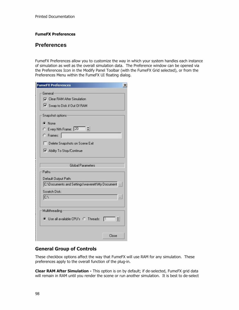
Printed Documentation
98
FumeFX Preferences
Preferences
FumeFX Preferences allow you to customize the way in which your system handles each instance of simulation as well as the overall simulation data. The Preference window can be opened via the Preferences Icon in the Modify Panel Toolbar (with the FumeFX Grid selected), or from the Preferences Menu within the FumeFX UI floating dialog.
General Group of Controls
These checkbox options affect the way that FumeFX will use RAM for any simulation. These preferences apply to the overall function of the plug-in. Clear RAM After Simulation - This option is on by default; if de-selected, FumeFX grid data will remain in RAM until you render the scene or run another simulation. It is best to de-select
Reference
99
this option if you want to run a simulation by one, or a few, steps at a time. This will save time since FumeFX won’t to save and load the simulation from disk with every simulation step. Another reason to turn this option off would be in order to save the fluid state in the snapshot file after the simulation has ended. Swap to Disk if Out of RAM - It is highly recommended that you keep simulation sizes within the available RAM. If this is not possible, this option makes FumeFX swap the simulation data to disk, resulting in about a tenfold increase in simulation times. Snapshot Options Group of Controls
These options affect the way you manage data from the individual states of a given simulation. These are local parameters, which are saved with each FumeFX instance. None - If checked, FumeFX will not save any simulation states. Ability to Stop/Continue checkbox - With this option enabled, all necessary data needed for FumeFX to stop and continue a simulation will be saved to disk. This means that once you have stopped your simulation, you can change any parameters and then continue from the frame that you stopped at.
The following options save the state of the simulation at specified frames, under the same name and path as output files, but with a different extension (.fdc). This makes it possible to continue the simulation from those frames, or use them as starting point for other simulations with the same grid size. Every Nth frame - This option saves the state of the simulation every N frames, relative to frame 0 on the time slider. Frames - With this option, you can save simulation states at specific frames. Enter your chosen frame numbers, separated by commas. Delete Snapshots on Scene Exit - This option will delete all “Nth frame” and “Selected frame” files when closing the scene or deleting the FumeFX object.
Global Parameters Group of Controls The preferences in this group define how FumeFX simulation files are handled. These parameters, like 3ds Max preferences, are independent of scene and FumeFX instances.
Path Options The parameters in this group affect the configuration of output files. Default Output Path - Here, the output path and file name will be automatically generated whenever a new FumeFX object is created. Inside the default output path, a directory will be created based on the scene name. Output file names will be generated as “FumeFX_Object_Name_FrameNumber.fxd.” If the scene is still untitled, a folder is created with a random file name, such as “FumeFX24345656.fxd.” Scratch Disk: This is where FumeFX will store all temporary information during simulations. It will default to your hard drive, although you can specify another location to use. You should
Printed Documentation
100
reserve a few GB of space on that drive, depending on the size of simulations you will run. Any files found there when you are not working with FumeFX are okay to delete.
Multithreading Group of Controls Multithreading options define the resources you use during simulation. You can choose whether to Use all available CPU's, or manually set the number of simulation Threads up to the current maximum of 16.

Reference
101
FusionWorks Renderer
FusionWorks Renderer
The FusionWorks Renderer is required for rendering and also serves to seamlessly blend between two or more overlapping FumeFX instances. It works not only within FumeFX, but also in combination with all other Sitni Sati volumetric plug-ins, such as DreamScape, AfterBurn and ScatterVL Pro. The FusionWorks Renderer is automatically added to the Environment list after you create the first instance of FumeFX in a scene. FusionWorks collects atmospheric samples from all of the compatible volumetric effects that the rendering ray traverses. Samples are collected separately for each object instance (FumeFX, for example) or each volumetric effect instance (e.g., AfterBurn). The sample step size for each is set by the corresponding plug-in. These samples are then sorted and blended together.
Parameters Rollout Global Step Scale - With this parameter you can change the rendering step size of all FusionWorks compatible plug-ins at once. Increase to accelerate the rendering, decrease if you experience rendering artifacts. Create Channels - Creates any of the following channels, which might be specific to a particular plug-in:
Particle Age - This applies only to AfterBurn.

Printed Documentation
102
Effect Channel - This allows you to apply rendering effects to compatible volumetrics. You must set the Effect ID in the compatible plug-in (AfterBurn and FumeFX). Image Motion Blur - This channel allows image motion blur on compatible volumetrics (AfterBurn, FumeFX).

Reference
103
Render Elements
Render Elements
Beyond standard rendering, FumeFX also supports 3ds Max's built-in Render Elements functionality. There are three available Render Element options for FumeFX: FumeFX Smoke, FumeFX: Fire and FusionWorks Z Depth passes. The first two export the simulated Smoke and Fire channels into separate passes. They have no additional parameters; and if there is more than one instance of FumeFX within the scene, their results will be blended into a single result. So ALL of the FumeFX Smoke effects would go onto a single layer, etc.
The FusionWorks Z Depth Render Element does have Min. and Max. spinners so that the user can input the scene depth that FumeFX should calculate it's pass on.
Printed Documentation
104
MAXScripting FumeFX
MAXScript & FumeFX
MAXScript is a powerful 3ds Max language that allows users to customize their interface, automate tasks, or increase functionality. FumeFX’s open architecture facilitates the use of this tool, which means you can tailor FumeFX to meet your own needs. Refer to the 3ds Max Reference Guide for general information on how to use this tool. Functions Exposed by FumeFX 3ds Max Objects Saving and Loading Presets
SavePresets <filename>presetFile This saves all current FumeFX settings to a preset file “presetFile.fxp” in default preset folder. The output returns false on error. LoadPresets <filename>presetFile <rollout_names_array>rollouts Use this to load all or some of the controls from the preset file “presetFile.fxp”. The output returns false upon error.
The Rollouts parameter is an array with some of the following values:
all: load all rollouts grid: load all rollouts from Grid Tab sim: load all rollouts from Simulation Tab render: load all rollouts from Render Tab illum: load all rollouts from Illumination Tab grid_dim: load Grid Tab / General Parameters Rollout grid_play: load Grid Tab / Playback Rollout grid_rec: load Grid Tab / Recording Param eters Rollout sim_main: load Simulation Tab / Simulation Rollout sim_smoke: load Simulation Tab / Smoke Rollout sim_fuel: load Simulation Tab / Fuel Rollout sim_temp: load Simulation Tab / Temperature Rollout sim_fm: load Simulation Tab / Fluid Mapping Rollout render_main: load Rendering Tab / Rendering Parameters
Reference
105
shader: load Rendering Tab / Shader Rollout
Examples:
-- have FumeFX01 save its settings to file mypreset.fxp in default presets folder $FumeFX01.SavePresets “mypreset1”
-- have selected FumeFX object load Render Tab > Render parameters rollup and Simulation Tab > Fuel rollup from file mypreset1.fxd.
$.LoadPresets "mypreset1" #(#render_main, #sim_fuel) -- have FumeFX01 load all rollouts in Grid Tab from file mypreset.fxd.
$FumeFX01.LoadPresets "mypreset" #grid
Simulation Control
RunSimulation() This does exactly the same as hitting the start button on the FumeFX Floater. Simulation will run from StartFrame to EndFrame.
SaveOutput <filename>outputFile This saves a .fxd type output file; note, you must enter the full file name. Output returns false on error.
SaveSim <filename>presetFile This saves a .fdc type simulation file; note, you must enter full file name. Output returns false on error.
GetPath() This returns the current base output file name without the frame number suffix. SetPath <filename>outputFile This sets output file name. You must enter the path and base file name; the extension is not necessary. $FumeFX01.SetPath “F:/temp/FumeFX/aa” $FumeFX01.SetPath “F:/temp/FumeFX/aa.fxd” AddSource <node>source Use this to attach FumeFX Sources to FumeFX. It is quivalent to picking a Source object in the Objects panel of the Floater Window.
RemoveSource <node>source Use this to remove Force FumeFX Sources from FumeFX. It is equivalent to removing a Source object in the Objects panel of the Floater Window.
AddForce <node>force Use this to attach Force objects like Wind to FumeFX. It is equivalent to picking a Force object in Objects panel of the Floater Window.
RemoveForce <node> force Use this to remove Force objects like Wind from FumeFX. It is equivalent to removing a Force object in Objects panel of the Floater Window.

Printed Documentation
106
FumeFX MAXScript Functions for Accessing the Simulation By learning to use FumeFX functions created for MAXScript, you can do almost anything that you want with FumeFX – including things not provided for in the default user interface. It is possible for you to plug in script between all significant phases of the simulation or even disable some simulation steps altogether. In this version of FumeFX, MAXScript cannot be called from the Listener, Macro Scripts, or in other way except from within FumeFX while the simulation is running or the output is being loaded. Preparation of the scripts takes place in the General panel of the Floater Window. You can access this by clicking the Edit Script button in the MAXScript rollout. If you create a script that will modify all of the voxels in a simulation (which could be tens of millions), it will execute at reasonable speeds, measured in seconds.
To get the feel of it, here is an example script: fn PostObjects = ( for i in 0 to (nx - 1) do for j in 0 to (ny - 1) do for k in 0 to (nz - 1) do SetSmoke i j k k/nz )
PostObjects is a “callback” function that FumeFX will call in every frame of the simulation after it has applied all sources and objects. It will go though all voxels in the adaptive grid (nx, ny and nz are global variables provided by FumeFX) and initialize the Smoke channel with a vertical gradient going from 0 to 1 over the local Z-axis. Channel is a set using voxel coordinates. MAXScript in FumeFX Simulation How it works: When you click Edit Script in the Simulation group, you will see a template in which to write your scripts. In it there are certain MAXScript functions that FumeFX will call during simulation. All of them are called once for each step of the simulation, unless otherwise noted. Callback Functions Note: Currently, the PostAdvection and PostPressure functions are for experimental use only, but are provided for those who are familiar with their use.
PreSim: Called once – at the beginning of simulation, before the first step has started, but after possible snapshot or stop/continue data has been loaded. PostSim: Called once - after the last step of the simulation has ended and while the simulation results are still in memory. PostObjects: Think of this as a scripted Source. It is called after the Adaptive grid has adjusted and FumeFX Sources, objects, and forces have all been applied. Here, you can additionally initialize the grid any way you like. Vorticity: This is the only place where Vorticity can be customized. The AddVort function allows every voxel can have its own Vorticity strength. Be aware that the stability of simulation can become unreliable when using values greater than 1.

Reference
107
PostForces: Buoyancy, Gravity, Vorticity, Motion Drag have been applied. Here you can apply custom forces such as: radial gravity, motion drag dependent on object distance, etc… PostAdvection: This is called after Velocities have moved through one step. If you have disabled FumeFX's Advection phase, you could theoretically write your own version in this function.
PostDiffuse: This is called after movement of Smoke and Fuel and their diffusion and dissipation. This is the proper time to set Fuel and Temperature values to control fires. PostStep: This is called following a whole simulation step, after the Fuel has been burned and diffusion and dissipation applied. You can set any kind of influence between channels here. If you have disabled FumeFX’s Burn phase, you could use this to burn Fuel your way.
Skipping FumeFX Simulation Phases If you want to skip certain FumeFX simulation phases completely, uncomment in the template, or write the following statements on the global level of the script:
skipForces = true skipAdvection = true skipPressure = true skipBurn = true
This is not recommended unless you have experience. A few examples of when you can skip certain phases are: You can skip Pressure and Advection phase if you simulate only the effects of diffusion. You can skip the Burn phase if you want to burn Fuel some other way. You can skip Forces if you want to apply buoyancy, gravity or motion drag in some specific way, such as depending on position or distance from objects. So, what can you do within these functions? Basically, you can get and set values for the main channels: Smoke, Fuel, Temperature and Velocity. You can also stop or cancel simulation and write messages to the FumeFX status window. Simulation Control Functions
ffxPrintToStatus <string>message This prints message to FumeFX status window during simulation. ffxStopSimulation() This is equivalent to pressing the Stop button in the status window. ffxCancelSimulation() This is equivalent to pressing the Cancel button in the status window. ffxHoldWindowOnce()

Printed Documentation
108
If this function is called during simulation, then after the simulation has stopped or cancelled, the simulation window will stay open, regardless of Hold Window checkbox selection.
Get Channel Functions Smoke is used in this example; however, all other channels are analogous. The ways to get Smoke values are:
GetSmoke <integer>i <integer>j <integer>k In this function, i, j, and k respectively represent the X, Y, and Z-axis coordinates in an adaptive grid. Voxel coordinates can range from 0 to nx-1 for i, 0 to ny–1 for j, and 0 to nz-1 for k. So, to get the smoke value in first voxel you would write
GetSmoke 0 0 0 Or, to get it from the top center voxel you would write: GetSmoke (nx/2) (ny/2) (nz)
GetSmokeByIndex <integer>index This is slightly faster than the form GetSmoke i j k. It uses only one parameter, voxel index, which is computed (i*ny + j)*nz + k.
To get the average value of smoke average = 0.0 for ind in 0 to (voxels-1) do (average += GetSmokeByIndex ind) average /= voxels
GetSmokeLocal <point3>lpt Here lpt is a point in a FumeFX object or local space. Unless the pivot is moved, the center of that coordinate system is the bottom center point of the FumeFX object. FumeFX dimensions are exposed through FumeFX nodes: Width, Length, and Height.
GetSmokeLocal [10.0, 10.0, $FumeFX01.Heigth/2]
GetSmokeWorld <point3>wpt <matrix3>FumeFXt Here wWpt is a position in world coordinates. You must also provide a FumeFX transformation matrix.
To get Smoke density at some object’s position wpt = $sensor01.position tm = $FumeFX01.transform if ((GetSmokeWorld wpt tm) > threshold) then myfunction()
These functions will return undefined if you ask for non-existing coordinates or coordinates outside of the grid. They will also return undefined if the channel has not been allocated – for example GetFuel() if Simulate Fire has been turned off in the Simulation tab. A complete list of set functions is:
float GetSmoke float GetSmokeByIndex float GetSmokeLocal

Reference
109
float GetSmokeWorld float GetTemp float GetTempByIndex float GetTempLocal float GetTempWorld float GetFuel float GetFuelByIndex float GetFuelLocal float GetFuelWorld point3 GetVel point3 GetVelByIndex point3 GetVelLocal point3 GetVelWorld
Usage of functions:
GetChannel i j k
GetChannelByIndex index GetChannelLocal lpt GetChannelWorld wpt TM
Index and i,j,k coordinates must be passed as integers. Set Channel Functions To set channel values, functions are provided that are analogous to the Get functions. They only have one additional parameter – value to set. Input ranges are not checked – so accuracy is important. The output can return true or false even if the value was, for some reason, not set. These functions set value at one voxel only – the voxel that the point belongs to.
SetSmoke <integer>i <integer>j <integer>k <float>value This uses adaptive grid voxel coordinates. SetSmokeByIndex <integer>index <float>value This uses voxel index.

Printed Documentation
110
SetSmokeLocal <point3>lpt <float>value This uses FumeFX local coordinates. SetSmokeWorld <point3>wpt <matrix3>FumeFXtm <float>value This uses world coordinates.
A complete list of set functions is:
float SetSmoke float SetSmokeByIndex float SetSmokeLocal float SetSmokeWorld float SetTemp float SetTempByIndex float SetTempLocal float SetTempWorld float SetFuel float SetFuelByIndex float SetFuelLocal float SetFuelWorld point3 SetVel point3 SetVelByIndex point3 SetVelLocal point3 SetVelWorld
Usage of functions:
SetChannel i j k value SetChannelByIndex index value SetChannelLocal lpt value SetChannelWorld wpt TM value

Reference
111
Smoke, Fuel and Temperature are float channels, and Velocity is a point3 channel. Remember to set the point3 channels with the point3 values, for example:
SetVelByIndex index [x,y,z]
More Channel Functions There are also functions for Vorticity and Turbulence. Used in simulation, they are cumulative with UI defined global Vorticity and Turbulence. If you wish to use only the scripted values, you must set Vorticity and Turbulence strength in the UI to 0. Note: Vorticity strengths above 1 may, in rare cases, make the simulation unstable. To add Turbulence, you can use:
AddTurb <integer>i <integer>j <integer>k <float>value AddTurbByIndex <integer>index <float>value AddVort functions can only be used during Vorticity callback. AddVort <integer>i <integer>j <integer>k <float>value AddVortByIndex <integer>index <float>value
You can fill the entire channel with a given value using the following functions:
FillSmoke <float>value FillFuel <float>value FillTemp <float>value FillVel <point3>value
MAXScript after Loading Output It is possible to post-process FumeFX output files at the time of loading. Here, for example, you can change the displayed result or the result used by the particles without affecting the simulation. Appropriate callback is called PostLoad. Example: To set smoke to any given minimum value throughout the entire grid, achieving a fog-like effect, enter the following script.
fn PostLoad = ( sm = 1.0 -- desired minimum smoke value
for i in 0 to (voxels-1) do (
s = GetSmokeByIndex if (s < sm) then ( SetSmokeByIndex sm )
)
Printed Documentation
112
)
Switching between Coordinates If you want to make modifications to FumeFX voxels, you will most often run loops in voxel space or index range. However, you may need to do some calculations in local or world space for some modifications. For this and similar cases, converter functions exist between various coordinate spaces that FumeFX uses. List of functions:
<integer> ffxVoxelPtToIndex <point3>vpt <point3> ffxVoxelPtToLocal <point3>vpt <point3> ffxVoxelPtToWorld <point3>vpt <point3> ffxIndexToVoxel <integer>ind <point3> ffxIndexToLocal <integer>ind <point3> ffxIndexToWorld <integer>ind <integer> ffxLocalPtToIndex <point3>lpt <point3> ffxLocalPtToVoxel <point3>lpt <point3> ffxLocalPtToWorld <point3>lpt <integer> ffxWorldPtToIndex <point3>wpt <point3> ffxWorldPtToVoxel <point3>wpt <point3> ffxWorldPtToLocal <point3>wpt VoxelPtTo… functions take point3 as argument, in adaptive grid coordinates, ranging [0.,0.,0.] – [nx, ny, nz]. IndexTo… functions take integer as argument, ranging from 0 to (voxels-1). LocalPtTo… functions take point3 as argument, in FumeFX local coordinates, ranging from [-Width/2, -Length/2, 0.] - [Width/2, Length/2, Height] for values inside the FumeFX grid. WorldPtTo… functions take point3 as argument, in world coordinates. IndexTo… functions must get valid index or they return undefined, other functions will convert between spaces regardless of whether the point is within FumeFX grid or not.
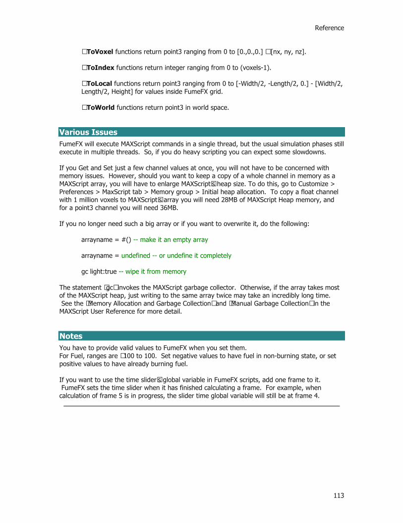
Reference
113
…ToVoxel functions return point3 ranging from 0 to [0.,0.,0.] – [nx, ny, nz]. …ToIndex functions return integer ranging from 0 to (voxels-1). …ToLocal functions return point3 ranging from 0 to [-Width/2, -Length/2, 0.] - [Width/2, Length/2, Height] for values inside FumeFX grid. …ToWorld functions return point3 in world space.
Various Issues FumeFX will execute MAXScript commands in a single thread, but the usual simulation phases still execute in multiple threads. So, if you do heavy scripting you can expect some slowdowns. If you Get and Set just a few channel values at once, you will not have to be concerned with memory issues. However, should you want to keep a copy of a whole channel in memory as a MAXScript array, you will have to enlarge MAXScript’s heap size. To do this, go to Customize > Preferences > MaxScript tab > Memory group > Initial heap allocation. To copy a float channel with 1 million voxels to MAXScript’s array you will need 28MB of MAXScript Heap memory, and for a point3 channel you will need 36MB. If you no longer need such a big array or if you want to overwrite it, do the following:
arrayname = #() -- make it an empty array arrayname = undefined -- or undefine it completely gc light:true -- wipe it from memory
The statement “gc” invokes the MAXScript garbage collector. Otherwise, if the array takes most of the MAXScript heap, just writing to the same array twice may take an incredibly long time. See the “Memory Allocation and Garbage Collection” and “Manual Garbage Collection” in the MAXScript User Reference for more detail. Notes You have to provide valid values to FumeFX when you set them. For Fuel, ranges are –100 to 100. Set negative values to have fuel in non-burning state, or set positive values to have already burning fuel. If you want to use the time slider’s global variable in FumeFX scripts, add one frame to it. FumeFX sets the time slider when it has finished calculating a frame. For example, when calculation of frame 5 is in progress, the slider time global variable will still be at frame 4.
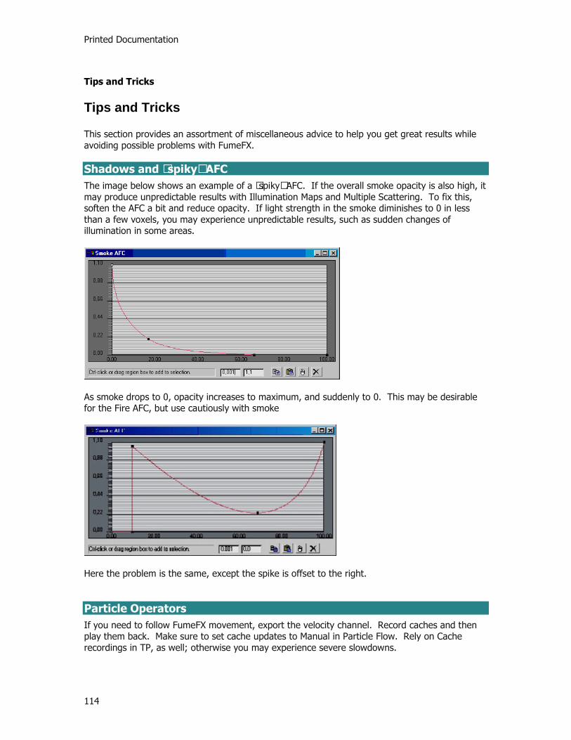
Printed Documentation
114
Tips and Tricks
Tips and Tricks
This section provides an assortment of miscellaneous advice to help you get great results while avoiding possible problems with FumeFX. Shadows and “spiky” AFC The image below shows an example of a “spiky” AFC. If the overall smoke opacity is also high, it may produce unpredictable results with Illumination Maps and Multiple Scattering. To fix this, soften the AFC a bit and reduce opacity. If light strength in the smoke diminishes to 0 in less than a few voxels, you may experience unpredictable results, such as sudden changes of illumination in some areas.
As smoke drops to 0, opacity increases to maximum, and suddenly to 0. This may be desirable for the Fire AFC, but use cautiously with smoke
Here the problem is the same, except the spike is offset to the right. Particle Operators If you need to follow FumeFX movement, export the velocity channel. Record caches and then play them back. Make sure to set cache updates to Manual in Particle Flow. Rely on Cache recordings in TP, as well; otherwise you may experience severe slowdowns.

Reference
115
Adaptive Grid Practices Adaptive Grid #1 If there is a source (Simple, Object, or Particle) that has no effect over a specific time range, set its Active key to off in that range. If you don’t, then in every frame FumeFX will repeatedly stretch its adaptive grid over the area, only to immediately shrink it back again when no values are applied. This obviously results in a waste of memory and time. Adaptive Grid #2 If you are using Object or Particle Sources, and that source’s bounding box stretches beyond FumeFX’ bounding box, FumeFX will, at every step, stretch the adaptive grid over the source and then, if no values are applied, shrink it back again. This results in a waste of memory and time. Adaptive Grid #3 How do you enlarge the adaptive grid through forces or turbulence? Set the grid’s adaptive sensitivity to 0,0. If there are no active sources in the grid, you will have to create one FumeFX Source. Set the source to Free Flow and set all its values to 0 (so it won’t change anything). Attach the source to FumeFX and the adaptive grid will start growing from that source’s location. Max 9 & Light Tracer You may get an assertion error in point3.h if you use Light Tracer with bounces set to a value of 1 or more. You can safely ignore this message. Simply click “Don’t show me this message again” and then “Continue”.
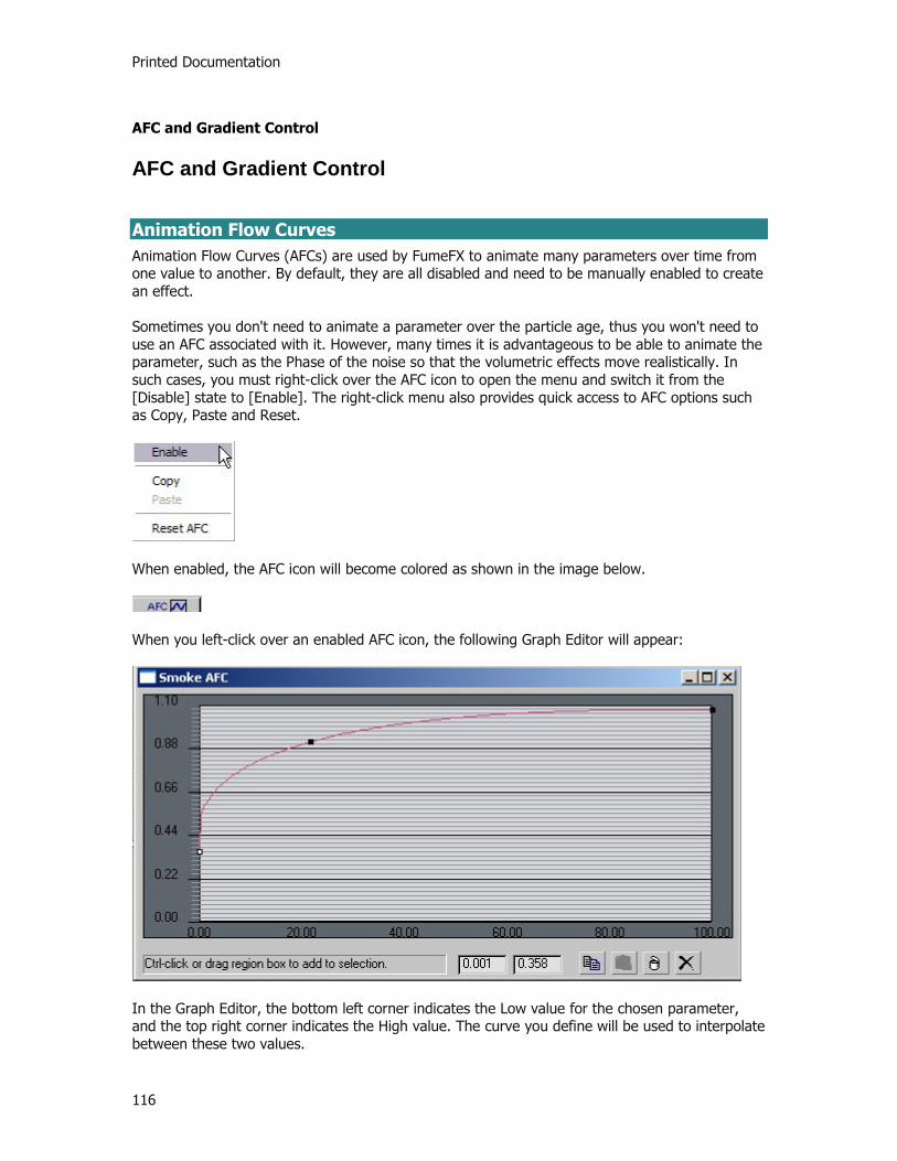
Printed Documentation
116
AFC and Gradient Control
AFC and Gradient Control
Animation Flow Curves Animation Flow Curves (AFCs) are used by FumeFX to animate many parameters over time from one value to another. By default, they are all disabled and need to be manually enabled to create an effect. Sometimes you don't need to animate a parameter over the particle age, thus you won't need to use an AFC associated with it. However, many times it is advantageous to be able to animate the parameter, such as the Phase of the noise so that the volumetric effects move realistically. In such cases, you must right-click over the AFC icon to open the menu and switch it from the [Disable] state to [Enable]. The right-click menu also provides quick access to AFC options such as Copy, Paste and Reset.
When enabled, the AFC icon will become colored as shown in the image below.
When you left-click over an enabled AFC icon, the following Graph Editor will appear:
In the Graph Editor, the bottom left corner indicates the Low value for the chosen parameter, and the top right corner indicates the High value. The curve you define will be used to interpolate between these two values.

Reference
117
You can change the key type by right-clicking on the points as shown below. Be aware that when you click on a point, it turns white to indicate it is active.
When you do you get another pop-up where you can choose the type of curve you want applied to that point.
Smooth – Creates a smooth curve, which has automatic tangent adjustment. Corner – Parts of the segment that are closer to the point will have linear characteristics. Bezier – Enables you to adjust the handles, which represent the curve slope at the point location.
There’s also a toolbar in the bottom right corner; its buttons are described below.
Copy - Allows you to copy all keys. Paste - Lets you paste keys from any other AFC. Delete - Removes all selected points. Reset - Resets the layout.
Keyboard Shortcuts when over a curve point:
Shift + left mouse button drag - restricts the movement to X-axis Ctrl + left mouse button drag - restricts the movement to Y-axis right mouse button - Pops up a menu (smooth, corner, delete key)
Gradient Controls Gradients are used to change the specific colors over the particle age. Gradients are accessible by clicking the small icon located on the FumeFX User Interface.

Printed Documentation
118
Some of the frequently used gradient options are accessible through the menu which is available by right-clicking the Gradient’s icon as shown below.
Keyless mode - In this mode the Gradient will behave as a single color picker where the color is constant throughout the particle life. Copy - Copy the selected gradient. Paste - Paste a selected gradient. Load - Load a previously saved gradient .AGT file. Save - Saves the selected gradient to an .AGT file. Reset - Clears all the keys and sets the Gradient’s state to the default.
When you left-click on the small gradient icon within the AfterBurn dialog, a larger dialog box will appear.
The left edge of the gradient is equivalent to the particle’s birth, while the right edge of the gradient is equivalent to the particle’s death. The status line is located above the gradient and shows the ID number of the currently edited key, with its color and position expressed as the particle age. To get the best accuracy out of a particle age status line, you must manually adjust the particle life (the default is 100) in the AfterBurn Particles Property dialog box. There are two types of the Gradient: Linear and TCB.
Linear - This gradient type uses the linear interpolation between the color keys. TCB - Tension, Continuity, Bias, Ease To (eT) and Ease From (eF) parameters provide a lot more flexibility than the Linear gradient type. By using these parameters, you can change the influence of each color key on the color interpolation along the segment.
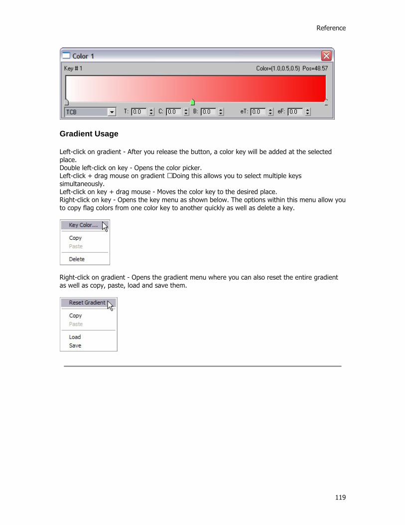
Reference
119
Gradient Usage
Left-click on gradient - After you release the button, a color key will be added at the selected place. Double left-click on key - Opens the color picker. Left-click + drag mouse on gradient – Doing this allows you to select multiple keys simultaneously. Left-click on key + drag mouse - Moves the color key to the desired place. Right-click on key - Opens the key menu as shown below. The options within this menu allow you to copy flag colors from one color key to another quickly as well as delete a key.
Right-click on gradient - Opens the gradient menu where you can also reset the entire gradient as well as copy, paste, load and save them.


121
Tutorials
Tutorial 1: Candle Flame
In this introductory tutorial you will learn how to use FumeFX at a basic level. It will also introduce you to the FumeFx UI.
1. In 3ds Max, select File->Open, and from your /Scenes/FumeFX/ Tutorials folder, select the file Tut_01_start.max.
This scene is nothing more than simple candle geometry. We're going to add the flame to the wick.
2. After the file loads, go to the Create Command Panel, select FumeFX from the dropdown list, then click on FumeFX.
3. From within the Top viewport, draw out a FumeFX Grid as shown below to roughly match the size of the simulation area at the top of the candle. Then in any viewport, move the FumeFX Grid gizmo into position at the top of the candle geometry.
NOTE: Make the FumeFX grid only as large as the simulation area you need. This will effect your simulation times in a big way. . Now that you have a FumeFX Grid in place, you need to create a Source to help drive the simulation.
4. Back within the Create Command Panel, go to the Helpers section, choose FumeFX from the dropdown menu, then select Object Src.
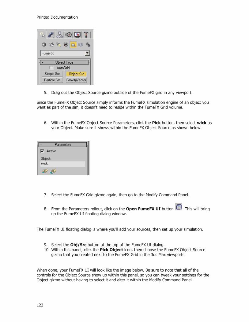
Printed Documentation
122
5. Drag out the Object Source gizmo outside of the FumeFX grid in any viewport. Since the FumeFX Object Source simply informs the FumeFX simulation engine of an object you want as part of the sim, it doesn't need to reside within the FumeFX Grid volume.
6. Within the FumeFX Object Source Parameters, click the Pick button, then select wick as your Object. Make sure it shows within the FumeFX Object Source as shown below.
7. Select the FumeFX Grid gizmo again, then go to the Modify Command Panel.
8. From the Parameters rollout, click on the Open FumeFX UI button . This will bring up the FumeFX UI floating dialog window.
The FumeFX UI floating dialog is where you'll add your sources, then set up your simulation.
9. Select the Obj/Src button at the top of the FumeFX UI dialog. 10. Within this panel, click the Pick Object icon, then choose the FumeFX Object Source
gizmo that you created next to the FumeFX Grid in the 3ds Max viewports.
When done, your FumeFX UI will look like the image below. Be sure to note that all of the controls for the Object Source show up within this panel, so you can tweak your settings for the Object gizmo without having to select it and alter it within the Modify Command Panel.

Tutorials
123
11. Under the FFX Object Source Parameters rollout make sure the amount of Fuel is set to 100 and the amount of Temperature is set to 300.
12. Next, click on the General button in the FumeFX UI.
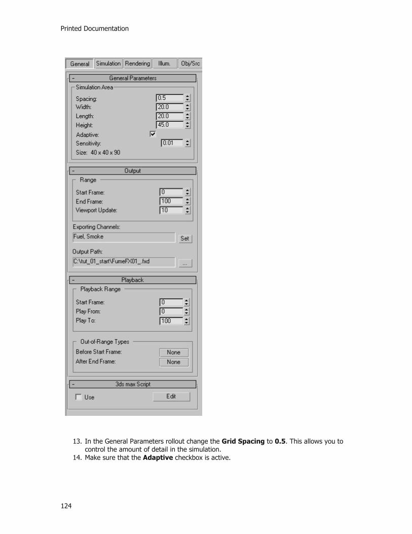
Printed Documentation
124
13. In the General Parameters rollout change the Grid Spacing to 0.5. This allows you to control the amount of detail in the simulation.
14. Make sure that the Adaptive checkbox is active.
Tutorials
125
15. Under the Output rollout you need to set an output path to store the simulation data. Click on the ellipsis (...) button next to the path and then create and set a new folder location on your hard disk to store the date.
A good option would be to put your simulation data into individual folders. Something on the order of creating a main folder \FumeFXSimData, and then creating new sub-folders for your different sims. You can create a new sub-folder for this one called \FFXTut01.
16. Now lets move on and select the Simulation tab.

Printed Documentation
126
17. Under the Simulation rollout make sure that Quality is set to 5, Maximum Iterations is set to 200 and the Time Scale is set to 1.
18. Under the System rollout, change Gravity to 0 and Buoyancy to 2.

Tutorials
127
19. Under the Fuel rollout, change the Ignition Temperature to 100, Burn Rate to 40 and the Burn Rate Variation to 0.1.
20. Now lets select the Rendering tab.
21. Under the Fire rollout set the Color spinner to 1.25, then right-click on the Color swatch and choose Key Mode.
22. Next, we want to build a gradient for the fire color. Since a candle's flame goes from orange to yellow to blue to black(transparent), that's our goal. Double-click on the gradient swatch to open up the Gradient dialog. Try and match your Fire Gradient to the image below.

Printed Documentation
128
23. Once the Gradient is set, close that dialog and check to make sure the Fire Opacity is set to 2.0.
24. Under the Smoke rollout change the Ambient Color to a dark Gray (RGB: 30, 30, 30) and the Opacity to 1.
25. Now we are all set to run the simulation.
26. Choose the start Simulation button from the top of the FumeFX UI dialog.
At this point, the simulation begins and you will see a progress dialog pop up.
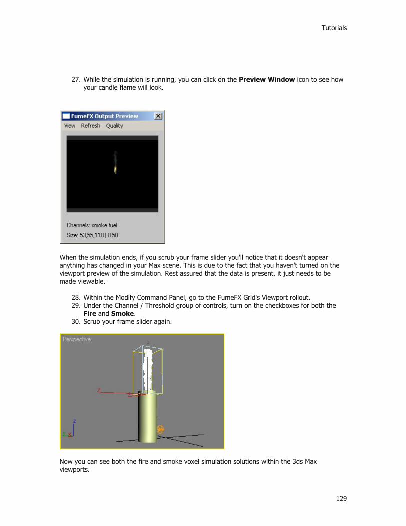
Tutorials
129
27. While the simulation is running, you can click on the Preview Window icon to see how your candle flame will look.
When the simulation ends, if you scrub your frame slider you'll notice that it doesn't appear anything has changed in your Max scene. This is due to the fact that you haven't turned on the viewport preview of the simulation. Rest assured that the data is present, it just needs to be made viewable.
28. Within the Modify Command Panel, go to the FumeFX Grid's Viewport rollout. 29. Under the Channel / Threshold group of controls, turn on the checkboxes for both the
Fire and Smoke. 30. Scrub your frame slider again.
Now you can see both the fire and smoke voxel simulation solutions within the 3ds Max viewports.

Printed Documentation
130
31. Next, turn the Smoke channel off from the Command Panel.
You're left with only the Fire channel's solution displayed in the 3ds Max viewports. What's more, is that you should be able to see the color gradient you set earlier displayed in the voxel viewport representation. This can be a VERY handy way to see how the various aspects of your simulation are reacting. What's more, it means if you want to tweak the coloration, you can do so now and see how it affects your calculated simulation without having to re-run it. Also, depending on how much height you gave your FumeFX Grid, you will most likely see the smoke hitting the top part of the volume and disappearing. Keep the boundary edges in mind when setting up your scenes. Depending on what effect you're after, you'll want to make sure you have enough room to let your simulations run naturally without hitting the boundaries of the volume.
32. Finally, make sure your Perspective viewport is active and render a frame.

Tutorials
131
On your own, you should render out the entire animation to see how the flame behaves. Also, experiment with the Gravity and Buoyancy spinners and re-run the simulation to see how these affect the movement and height of the flame and surrounding smoke. While fairly simple, this first tutorial should have given you some ideas of the potential and power within FumeFX. We're not done yet - there's still more to come. Continue to Tutorial 2

Printed Documentation
132
Tutorial 1: Candle Flame
In this introductory tutorial you will learn how to use FumeFX at a basic level. It will also introduce you to the FumeFx UI.
1. In 3ds Max, select File->Open, and from your /Scenes/FumeFX/ Tutorials folder, select the file Tut_01_start.max.
This scene is nothing more than simple candle geometry. We're going to add the flame to the wick.
2. After the file loads, go to the Create Command Panel, select FumeFX from the dropdown list, then click on FumeFX.
3. From within the Top viewport, draw out a FumeFX Grid as shown below to roughly match the size of the simulation area at the top of the candle. Then in any viewport, move the FumeFX Grid gizmo into position at the top of the candle geometry.
NOTE: Make the FumeFX grid only as large as the simulation area you need. This will effect your simulation times in a big way. . Now that you have a FumeFX Grid in place, you need to create a Source to help drive the simulation.
4. Back within the Create Command Panel, go to the Helpers section, choose FumeFX from the dropdown menu, then select Object Src.

Tutorials
133
5. Drag out the Object Source gizmo outside of the FumeFX grid in any viewport. Since the FumeFX Object Source simply informs the FumeFX simulation engine of an object you want as part of the sim, it doesn't need to reside within the FumeFX Grid volume.
6. Within the FumeFX Object Source Parameters, click the Pick button, then select wick as your Object. Make sure it shows within the FumeFX Object Source as shown below.
7. Select the FumeFX Grid gizmo again, then go to the Modify Command Panel.
8. From the Parameters rollout, click on the Open FumeFX UI button . This will bring up the FumeFX UI floating dialog window.
The FumeFX UI floating dialog is where you'll add your sources, then set up your simulation.
9. Select the Obj/Src button at the top of the FumeFX UI dialog. 10. Within this panel, click the Pick Object icon, then choose the FumeFX Object Source
gizmo that you created next to the FumeFX Grid in the 3ds Max viewports.
When done, your FumeFX UI will look like the image below. Be sure to note that all of the controls for the Object Source show up within this panel, so you can tweak your settings for the Object gizmo without having to select it and alter it within the Modify Command Panel.
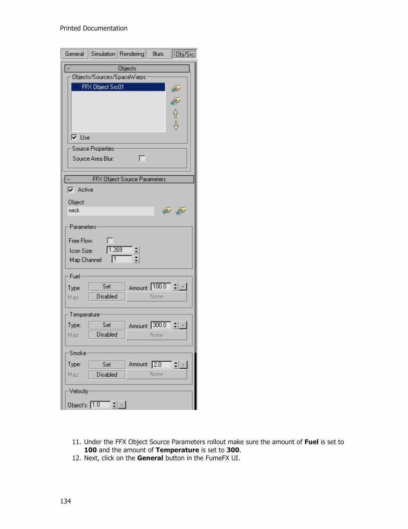
Printed Documentation
134
11. Under the FFX Object Source Parameters rollout make sure the amount of Fuel is set to 100 and the amount of Temperature is set to 300.
12. Next, click on the General button in the FumeFX UI.

Tutorials
135
13. In the General Parameters rollout change the Grid Spacing to 0.5. This allows you to control the amount of detail in the simulation.
14. Make sure that the Adaptive checkbox is active.
Printed Documentation
136
15. Under the Output rollout you need to set an output path to store the simulation data. Click on the ellipsis (...) button next to the path and then create and set a new folder location on your hard disk to store the date.
A good option would be to put your simulation data into individual folders. Something on the order of creating a main folder \FumeFXSimData, and then creating new sub-folders for your different sims. You can create a new sub-folder for this one called \FFXTut01.
16. Now lets move on and select the Simulation tab.

Tutorials
137
17. Under the Simulation rollout make sure that Quality is set to 5, Maximum Iterations is set to 200 and the Time Scale is set to 1.
18. Under the System rollout, change Gravity to 0 and Buoyancy to 2.
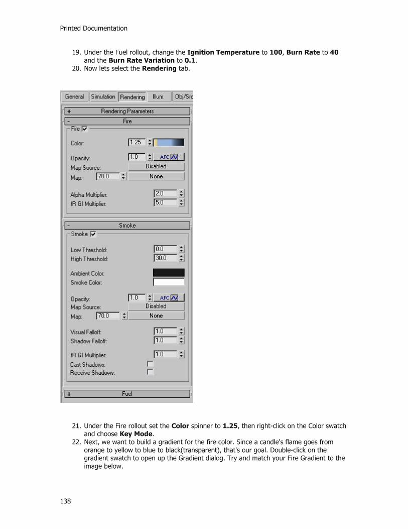
Printed Documentation
138
19. Under the Fuel rollout, change the Ignition Temperature to 100, Burn Rate to 40 and the Burn Rate Variation to 0.1.
20. Now lets select the Rendering tab.
21. Under the Fire rollout set the Color spinner to 1.25, then right-click on the Color swatch and choose Key Mode.
22. Next, we want to build a gradient for the fire color. Since a candle's flame goes from orange to yellow to blue to black(transparent), that's our goal. Double-click on the gradient swatch to open up the Gradient dialog. Try and match your Fire Gradient to the image below.
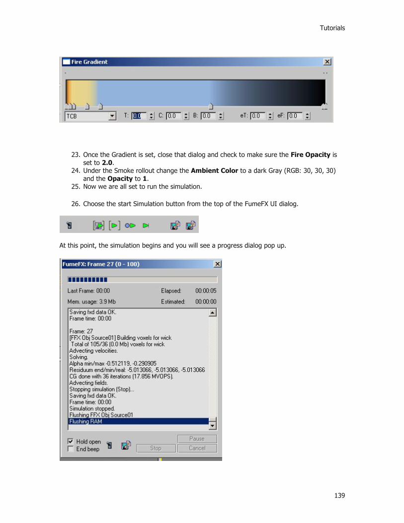
Tutorials
139
23. Once the Gradient is set, close that dialog and check to make sure the Fire Opacity is set to 2.0.
24. Under the Smoke rollout change the Ambient Color to a dark Gray (RGB: 30, 30, 30) and the Opacity to 1.
25. Now we are all set to run the simulation.
26. Choose the start Simulation button from the top of the FumeFX UI dialog.
At this point, the simulation begins and you will see a progress dialog pop up.

Printed Documentation
140
27. While the simulation is running, you can click on the Preview Window icon to see how your candle flame will look.
When the simulation ends, if you scrub your frame slider you'll notice that it doesn't appear anything has changed in your Max scene. This is due to the fact that you haven't turned on the viewport preview of the simulation. Rest assured that the data is present, it just needs to be made viewable.
28. Within the Modify Command Panel, go to the FumeFX Grid's Viewport rollout. 29. Under the Channel / Threshold group of controls, turn on the checkboxes for both the
Fire and Smoke. 30. Scrub your frame slider again.
Now you can see both the fire and smoke voxel simulation solutions within the 3ds Max viewports.

Tutorials
141
31. Next, turn the Smoke channel off from the Command Panel.
You're left with only the Fire channel's solution displayed in the 3ds Max viewports. What's more, is that you should be able to see the color gradient you set earlier displayed in the voxel viewport representation. This can be a VERY handy way to see how the various aspects of your simulation are reacting. What's more, it means if you want to tweak the coloration, you can do so now and see how it affects your calculated simulation without having to re-run it. Also, depending on how much height you gave your FumeFX Grid, you will most likely see the smoke hitting the top part of the volume and disappearing. Keep the boundary edges in mind when setting up your scenes. Depending on what effect you're after, you'll want to make sure you have enough room to let your simulations run naturally without hitting the boundaries of the volume.
32. Finally, make sure your Perspective viewport is active and render a frame.

Printed Documentation
142
On your own, you should render out the entire animation to see how the flame behaves. Also, experiment with the Gravity and Buoyancy spinners and re-run the simulation to see how these affect the movement and height of the flame and surrounding smoke. While fairly simple, this first tutorial should have given you some ideas of the potential and power within FumeFX. We're not done yet - there's still more to come. Continue to Tutorial 2
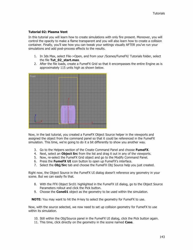
Tutorials
143
Tutorial 02: Plasma Vent
In this tutorial you will learn how to create simulations with only fire present. Moreover, you will control the opacity to make a flame transparent and you will also learn how to create a collision container. Finally, you'll see how you can tweak your settings visually AFTER you've run your simulations and add post-process effects to the results.
1. In 3ds Max, select File->Open, and from your /Scenes/FumeFX/ Tutorials folder, select the file Tut_02_start.max.
2. After the file loads, create a FumeFX Grid so that it encompasses the entire Engine as is approximately 115 units high as shown below.
Now, in the last tutorial, you created a FumeFX Object Source helper in the viewports and assigned the object from the command panel so that it could be referenced in the FumeFX simulation. This time, we're going to do it a bit differently to show you another way.
3. Go to the Helpers section of the Create Command Panel and choose FumeFX. 4. Next, select an Object Src from the list and drag it out in any of the viewports. 5. Now, re-select the FumeFX Grid object and go to the Modify Command Panel. 6. Press the FumeFX UI icon button to open up FumeFX's interface. 7. Select the Obj/Src tab and choose the FumeFX Obj Source help you just created.
Right now, the Object Source in the FumeFX UI dialog doesn't reference any geometry in your scene. But we can easily fix that.
8. With the FFX Object Src01 highlighted in the FumeFX UI dialog, go to the Object Source Parameters rollout and click the Pick button.
9. Choose the Cone01 object as the geometry to be used within the simulation.
NOTE: You may want to hit the H-key to select the geometry for FumeFX to use. Now, with the source selected, we now need to set up collision geometry for FumeFX to use within its simulation.
10. Still within the Obj/Source panel in the FumeFX UI dialog, click the Pick button again. 11. This time, click directly on the geometry in the scene named Case.
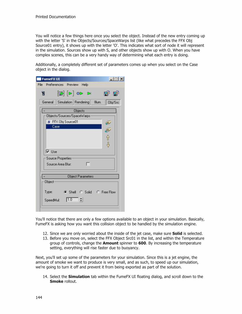
Printed Documentation
144
You will notice a few things here once you select the object. Instead of the new entry coming up with the letter 'S' in the Objects/Sources/SpaceWarps list (like what precedes the FFX Obj Source01 entry), it shows up with the letter 'O'. This indicates what sort of node it will represent in the simulation. Sources show up with S, and other objects show up with O. When you have complex scenes, this can be a very handy way of determining what each entry is doing. Additionally, a completely different set of parameters comes up when you select on the Case object in the dialog.
You'll notice that there are only a few options available to an object in your simulation. Basically, FumeFX is asking how you want this collision object to be handled by the simulation engine.
12. Since we are only worried about the inside of the jet case, make sure Solid is selected. 13. Before you move on, select the FFX Object Src01 in the list, and within the Temperature
group of controls, change the Amount spinner to 600. By increasing the temperature setting, everything will rise faster due to buoyancy.
Next, you'll set up some of the parameters for your simulation. Since this is a jet engine, the amount of smoke we want to produce is very small, and as such, to speed up our simulation, we're going to turn it off and prevent it from being exported as part of the solution.
14. Select the Simulation tab within the FumeFX UI floating dialog, and scroll down to the Smoke rollout.

Tutorials
145
15. Click on the Simulate Smoke checkbox to de-activate it. This will allow us to exclude smoke calculation from the simulation.
16. Next, within the Simulation group of controls, make sure that Advection Stride is set to 0.3.
These settings will help make sure that the flames coming from the vent do not slow down too much as they move away from the source and dissipate.
17. Under the System group of controls, set the Vorticity spinner to 0.4 and set the X Turbulence spinner to 0.4 as well. This will give the plasma flames some subtle waves and natural motion.
18. After this, go to the Fuel rollout and set the Ignition Temperature to 0, Burn Rate to 12, Burn Rate Variation to 0.2 and Expansion to 0.6.
These settings work in concert to determine how fast and hot the fuel will burn and how much pressure it puts on the simulation volume.
19. Next, select the General Tab and set an output path from the Output rollout. If you followed our suggestion from the first tutorial, simply create a new folder called \Tut02 under the \FFXSimData folder and use it for the jet engine simulation data. While you are in the General tab, make sure the Spacing spinner is set to 2.0. We don't want super detailed plasma flames, and this setting will also help keep sim times low.
20. Next, click the Set button within the Exporting Channels: section to bring up the Select Channels For Output dialog.
21. If it isn't already in the Excluded Channels window, select the Smoke entry in the Exported Channels window, and click the double-arrow button so it moves into the Excluded Channels window.
22. Then click OK to close this dialog.
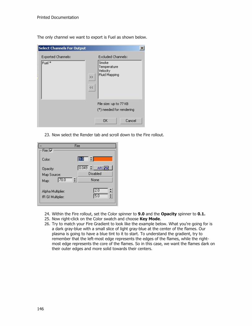
Printed Documentation
146
The only channel we want to export is Fuel as shown below.
23. Now select the Render tab and scroll down to the Fire rollout.
24. Within the Fire rollout, set the Color spinner to 9.0 and the Opacity spinner to 0.1. 25. Now right-click on the Color swatch and choose Key Mode. 26. Try to match your Fire Gradient to look like the example below. What you're going for is
a dark gray-blue with a small slice of light gray-blue at the center of the flames. Our plasma is going to have a blue tint to it to start. To understand the gradient, try to remember that the left-most edge represents the edges of the flames, while the right-most edge represents the core of the flames. So in this case, we want the flames dark on their outer edges and more solid towards their centers.

Tutorials
147
Next, you need to create an Animation Flow Curve to control how the Opacity of the flame is handled.
27. Click on the AFC button (it is active by default) to open the curve editor. 28. Now the default curve is not waht we want, so click the Delete button (the small X) to
reset the AFC curve to it's default linear state. 29. Next, move the two end points of the curve to match the position of the curve shown
below, and then add a point roughly in the middle to give it some curvature.
When done, close the Fire AFC dialog. Now, let's do a quick check:
FumeFX UI placed where we want the simulation to occur? CHECK. FumeFX Source object helper created to reference our scene geometry to be used as a
fuel source? CHECK. Other scene geometry selected to be used as a collision object in simulation? CHECK. Simulation channels determined and set up (remember turning off the Smoke channel)?
CHECK. Simulation parameters adjusted for a sample run? CHECK.
Alrighty then - you are ready to run your simulation and see what you've got.
30. Before you start your simulation, let's open the Preview Window by clicking on it's button in the FumeFX UI (the light switch icon).
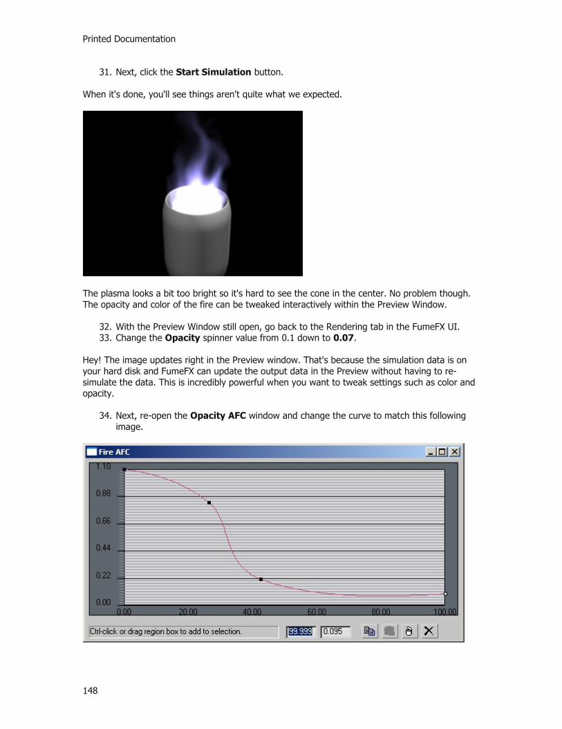
Printed Documentation
148
31. Next, click the Start Simulation button. When it's done, you'll see things aren't quite what we expected.
The plasma looks a bit too bright so it's hard to see the cone in the center. No problem though. The opacity and color of the fire can be tweaked interactively within the Preview Window.
32. With the Preview Window still open, go back to the Rendering tab in the FumeFX UI. 33. Change the Opacity spinner value from 0.1 down to 0.07.
Hey! The image updates right in the Preview window. That's because the simulation data is on your hard disk and FumeFX can update the output data in the Preview without having to re-simulate the data. This is incredibly powerful when you want to tweak settings such as color and opacity.
34. Next, re-open the Opacity AFC window and change the curve to match this following image.

Tutorials
149
Again, the Preview Window will update to show you the changes to your flames as you add and move the knots in the Opacity gradient around. Now, let's say that the client decides that blue isn't the color they really want - they want it to be green. No problem.
35. Click on the Color gradient swatch again, and change it as follows:
When you render again, the plasma fire will have changed color, and you didn't have to re-sim!
What makes this SO powerful is that it frees you to make changes to various aspects of your simulation after you've run it. This should unleash your creative side and let you tweak until you've got it just how you envisioned the effect looking. Adding Post Effects Next, we're going to add a Lens Effects glow to this plasma to give it some "bloom" in a final render. In order to do this, you'll need to do a few things:
Assign an Effects Channel to the simulation. Tell Fusionworks to generate Effects Channels. Build the Lens Effects Glow effect and make it key off of the Effect channel set in
FumeFX. Let's get started.
1. Within the FumeFX UI floating dialog, go to the Rendering tab. 2. Under the Rendering Parameters rollout, change the Effects Channel spinner value to
1. 3. Now, go to your 3ds Max environment tab (hit '8' as a quick shortcut to get to it).

Printed Documentation
150
Within this dialog, you'll find the FusionWorks renderer listed under the Atmospheric effects. It is placed there automatically when you start working with FumeFX. In order to get a glow effect to work, you FusionWorks needs to generate channels for use by other post process effects like glows.
4. Highlight the Fusionworks renderer and from the Parameters rollout, click in the Create Channels checkbox to activate it.
5. Next, activate the Effects Channel checkbox as well.
Now that the effect channel can be created, it's time to add the Lens Effects Glow to your FumeFX output.
6. Click on the Effects tab in the Environment and Effects dialog, and hit Add. Choose Lens Effects from the pop-up dialog.
7. Now, within the Lens Effects Parameters rollout, highlight the Glow element and hit the arrow to add it to the active effects.
8. Next, scroll down to the Glow Element rollout, and click on the Options tab. 9. Within the Apply Element To: group of controls, choose Image. Turn the other
checkboxes off if they are on. 10. Now under the Image Sources group of controls, activate the checkbox for Material
ID, and change it's spinner value to 1. This will match the Effects Channel you set earlier inside of the FumeFX UI floating dialog.
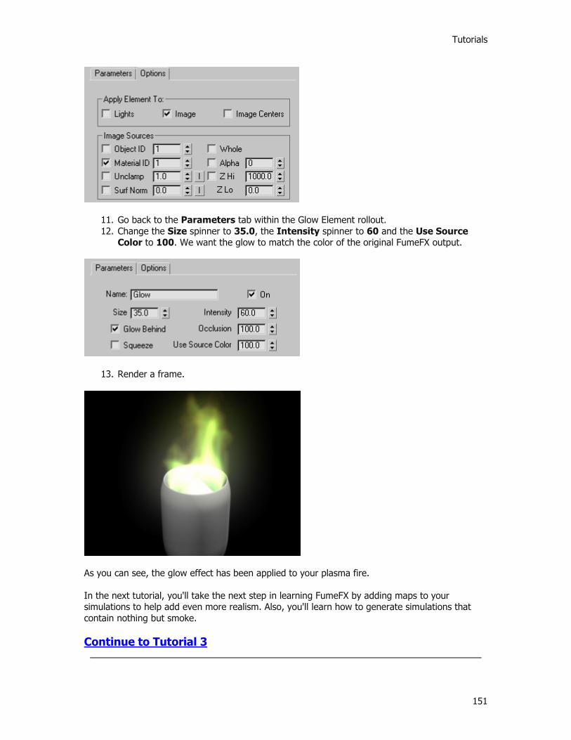
Tutorials
151
11. Go back to the Parameters tab within the Glow Element rollout. 12. Change the Size spinner to 35.0, the Intensity spinner to 60 and the Use Source
Color to 100. We want the glow to match the color of the original FumeFX output.
13. Render a frame.
As you can see, the glow effect has been applied to your plasma fire. In the next tutorial, you'll take the next step in learning FumeFX by adding maps to your simulations to help add even more realism. Also, you'll learn how to generate simulations that contain nothing but smoke. Continue to Tutorial 3

Printed Documentation
152

Tutorials
153
Tutorial 03: Cigarette Smoke
In this next tutorial you will learn how to use noise maps to control the look of your smoke.
1. In 3ds Max, select File->Open, and from your /Scenes/FumeFX/ Tutorials folder, select the file Tut_03_Start.max.
2. Create a FumeFX Grid over the cigarette in the Top or Perspective viewport. Make sure the height of the FumeFX Grid volume is about 115 units.
3. Next, create a FumeFX Source Object helper in any viewport then select the object named fire for your object source (this is the tip of the cigarette).
4. Re-select your FumeFX Grid and go to the Modify Command Panel, then open the FumeFX UI floating dialog.
5. As you have done in previous tutorials, Go to the General tab and set your output path for the simulation to be stored. If you've followed our suggestion, simply create a new sub-folder called \Tut03 beneath the \FumeFXSimData folder.
Now that the path is set up, let's start setting our smoke up for our cigarette.
6. Still within the General tab, go to the Simulation Area group of controls and set the Spacing value to 0.4.
This will result in a denser simulation grid of voxels, and will result in a more detailed simulation. Understand this will also take up more disk space to store and longer to sim. But since we're going for realism here, this should do the trick.
7. Next set the Sensitivity spinner to 0.05. 8. Once complete, select the Simulation tab in the FumeFX UI floating dialog. 9. Under the Simulation group of controls set the spinners to the following values:
Quality spinner to 4. Maximum Iterations spinner to 100. Advection Stride spinner to 0.3 Time Scale spinner to 2.

Printed Documentation
154
10. Next, go to the System group of controls and change the following spinners to values provided:
Buoyancy spinner to 1.5. Vorticity spinner to 0.1. X Turbulence spinner to 0.03. (NOTE: that this value will affect X, Y and Z
turbulence values since they are currently linked)
Once these parameters are set for our smoke, we need to tell FumeFX NOT to generate any fuel, which would create fire as well. Obviously, for a cigarette, we don't want the end burning like a match or candle. We just want the smoke to be simulated and emitted from the tip.
11. Under the Fuel group of controls, click on the Simulate Fuel checkbox to de-select it. 12. To continue this process of turning off Fuel and Fire, go to the Rendering tab next and
within the Fire rollout, click on the Fire checkbox to de-select it as well. 13. Still within the Rendering tab, under the Smoke rollout change the Opacity spinner to 5.
This will help give you more visible cigarette smoke. Once complete, the only thing that will generate within this scene is Smoke. Now you need to tweak the smoke parameters directly. This involves adding all of your sources and objects to the simulation engine.
14. Select the Obj/Src tab in the FumeFX UI floating dialog. 15. Click on the Pick button, and within the 3ds Max viewports, choose the FFX Object
Src01 you created earlier. This will act as the smoke generation source. 16. Click the Pick button again, and this time choose both the Cylinder and butt objects
from within the 3ds Max viewports. They will show up as Objects (prefaced with the letter 'O') within the simulation and will collide with the smoke as the cigarette animates.

Tutorials
155
Okay, so you have your sources now for the simulation. Let's now look at some of the advanced controls for your sources.
17. Highlight the FFX Object Src01 within the list. 18. Next, go to the Fuel group of controls and click the button that says Set (next to the
Type label). Choose Channel is Disabled from the pop-up list. Again, we want to turn off fuel calculations in this sim.
Next, you'll add a procedural Noise texture map as a mask for the smoke to help control the look.
19. Within the Smoke group of controls, click on the button labeled Disabled and choose Source from Intensity from the pop-up list. This will activate the Map slot next to it.
20. Now click on the Map slot button that says None. This will bring up the standard Material/Map browser.
21. Choose Noise in the Material/Map browser so that it shows in the map slot in the FumeFX UI floating dialog.
22. Next, open the 3ds Max Material Editor so you can edit the Noise map. 23. Simply drag and drop the Noise map from the Smoke group of controls in FumeFX to a
blank material slot in the Material Editor. 24. Under the Noise Parameters rollout, make sure that Regular is the Noise Type and
change the Size spinner to 6.35. 25. Close the Material Editor.

Printed Documentation
156
At this point, let's go through our checklist for a smoke-only simulation:
FumeFX UI placed where we want the simulation to occur? CHECK. FumeFX Source object helper created to reference our scene geometry to be used as a
smoke source? CHECK. Other scene geometry selected to be used as a collision objects in simulation? CHECK. All Fuel and Fire creation checkboxes de-activated? CHECK. Simulation parameters adjusted for a sample run? CHECK.
Now you are ready to run a test simulation.
26. Open the Preview Window so you can monitor the output. 27. Click on the Start Simulation button within the FumeFX UI floating dialog.
NOTE: This simulation may take between 20-40 minutes to simulate depending on your machine's processing power, and will take up approximately 800MB of disk space for the data storage as designed. If you would prefer, you can knock down the Quality spinner from 4 to 2, and adjust the Spacing spinner from 0.4 to 0.8 to help reduce the time and space required. 28. Once the simulation is complete, render the animation out to see your result.
Within the Preview Window, simply by scrubbing the frame slider after the simulation is complete, you should notice the smoke moving with the cigarette source and how the base of the cigarette acts as a collision object. You can see how the noise map is affecting the smoke patterns. On your own, you can play with different map types to see how they affect the smoke generation. If you want, turn off the Noise map and re-simulate to see exactly how much detail
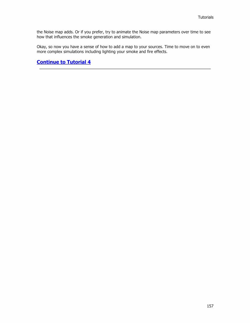
Tutorials
157
the Noise map adds. Or if you prefer, try to animate the Noise map parameters over time to see how that influences the smoke generation and simulation. Okay, so now you have a sense of how to add a map to your sources. Time to move on to even more complex simulations including lighting your smoke and fire effects. Continue to Tutorial 4
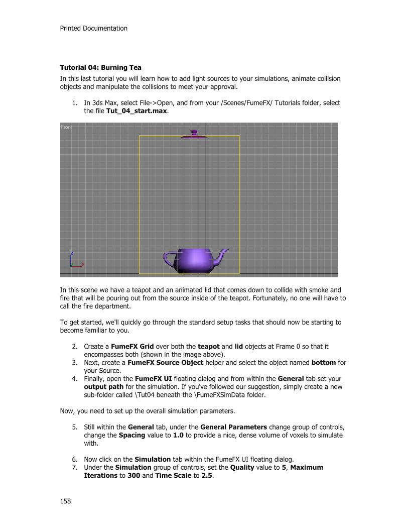
Printed Documentation
158
Tutorial 04: Burning Tea
In this last tutorial you will learn how to add light sources to your simulations, animate collision objects and manipulate the collisions to meet your approval.
1. In 3ds Max, select File->Open, and from your /Scenes/FumeFX/ Tutorials folder, select the file Tut_04_start.max.
In this scene we have a teapot and an animated lid that comes down to collide with smoke and fire that will be pouring out from the source inside of the teapot. Fortunately, no one will have to call the fire department. To get started, we'll quickly go through the standard setup tasks that should now be starting to become familiar to you.
2. Create a FumeFX Grid over both the teapot and lid objects at Frame 0 so that it encompasses both (shown in the image above).
3. Next, create a FumeFX Source Object helper and select the object named bottom for your Source.
4. Finally, open the FumeFX UI floating dialog and from within the General tab set your output path for the simulation. If you've followed our suggestion, simply create a new sub-folder called \Tut04 beneath the \FumeFXSimData folder.
Now, you need to set up the overall simulation parameters.
5. Still within the General tab, under the General Parameters change group of controls, change the Spacing value to 1.0 to provide a nice, dense volume of voxels to simulate with.
6. Now click on the Simulation tab within the FumeFX UI floating dialog. 7. Under the Simulation group of controls, set the Quality value to 5, Maximum
Iterations to 300 and Time Scale to 2.5.

Tutorials
159
8. Within the System group of controls, set Gravity to 0, Buoyancy to 0.7 and Vorticity to 1.0.
9. Now go to the Fuel rollout and set the following parameters: Ignition Temperature spinner to 0 Burn Rate spinner to 10.0 Burn Rate Variation spinner to 1.0. Expansion spinner to 2.0.
10. After those are set, click on the Rendering tab in the FumeFX UI floating dialog. 11. Go to the Fire rollout, and then right-click on the Fire Gradient color swatch. Choose Key
Mode to turn it into a gradient. 12. Change the Fire Gradient colors to roughly match the image below. This will give the fire
a nice warm color.
13. Move further down the Rendering tab to the Smoke rollout and change the Smoke Opacity spinner value to 20.0.
With many of the parameters set for the fire and smoke, it's time to move onto lighting. Lights can be added directly into the FumeFX simulation in order to have them affect the coloration and illumination of the smoke within the final rendered output. This includes support for multiple scattering, which gives smoke nice softness when it interacts with other scene objects.
14. Select the Illumination tab in the FumeFX UI. There is currently one Omni light in the scene with standard 3ds Max shadow maps, and we'll use this to illuminate the smoke and fire (and the teapot) in the simulation.
15. Click on the Pick button and then select the Onmi01 as your light source.

Printed Documentation
160
Just as is the case with the Obj/Src list window, the Omni light will now show within the window.
16. Still within the Illumination tab, make sure that the Multiple Scattering checkbox is activated so we can manipulate how the lighting will blend into the smoke and fire.
17. Next, change the Multiple Scattering parameters as follows: Maximum Depth spinner to 5 Fire Strength spinner to 0.7 Smoke Strength spinner to 0.01 Falloff spinner to 5.0
Finally, it's time to add our Sources and collisions to the FumeFX simulation system.
18. Select the Obj/SRC tab in the FumeFX UI floating dialog and click the Pick button. 19. In the 3ds Max viewports, select the FFX Object Src01 you created earlier as your
Source. 20. Next, click the Pick button again, and select the teapot bottom (named body). Change
the collision type to Shell. This will tell FumeFX that the object is hollow and it will allow internal interactions with the simulation as such as the teapot bursts into flames.
21. Finally, click the Pick button one more time and choose the teapot top (named top surprisingly enough) and change its collision type to Shell just as you did with the body. Then change the SpeedMul spinner value to 3.0. This gives the collision object a little force around it to collide with the smoke and fire.
At this point, you should have all three of your objects in the scene as shown below.
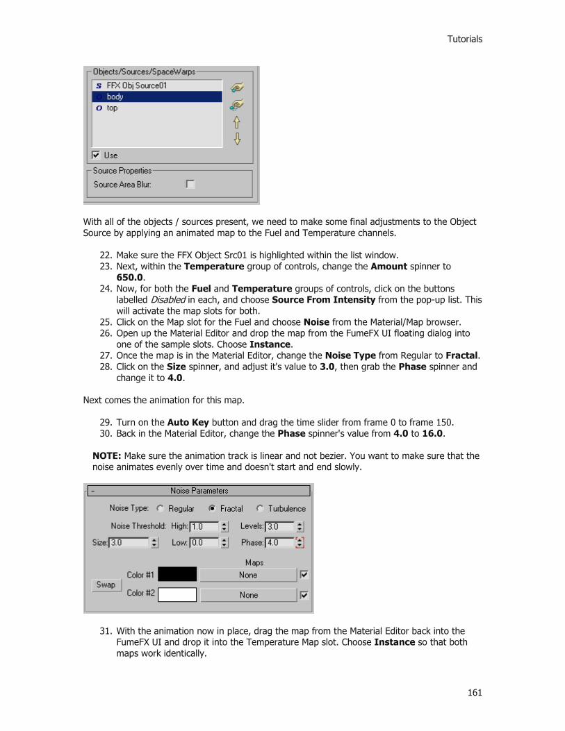
Tutorials
161
With all of the objects / sources present, we need to make some final adjustments to the Object Source by applying an animated map to the Fuel and Temperature channels.
22. Make sure the FFX Object Src01 is highlighted within the list window. 23. Next, within the Temperature group of controls, change the Amount spinner to
650.0. 24. Now, for both the Fuel and Temperature groups of controls, click on the buttons
labelled Disabled in each, and choose Source From Intensity from the pop-up list. This will activate the map slots for both.
25. Click on the Map slot for the Fuel and choose Noise from the Material/Map browser. 26. Open up the Material Editor and drop the map from the FumeFX UI floating dialog into
one of the sample slots. Choose Instance. 27. Once the map is in the Material Editor, change the Noise Type from Regular to Fractal. 28. Click on the Size spinner, and adjust it's value to 3.0, then grab the Phase spinner and
change it to 4.0. Next comes the animation for this map.
29. Turn on the Auto Key button and drag the time slider from frame 0 to frame 150. 30. Back in the Material Editor, change the Phase spinner's value from 4.0 to 16.0.
NOTE: Make sure the animation track is linear and not bezier. You want to make sure that the noise animates evenly over time and doesn't start and end slowly.
31. With the animation now in place, drag the map from the Material Editor back into the FumeFX UI and drop it into the Temperature Map slot. Choose Instance so that both maps work identically.
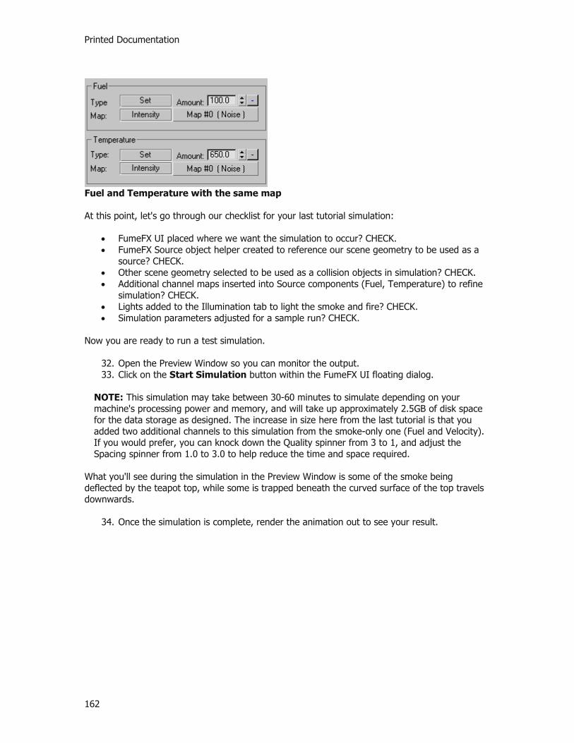
Printed Documentation
162
Fuel and Temperature with the same map At this point, let's go through our checklist for your last tutorial simulation:
FumeFX UI placed where we want the simulation to occur? CHECK. FumeFX Source object helper created to reference our scene geometry to be used as a
source? CHECK. Other scene geometry selected to be used as a collision objects in simulation? CHECK. Additional channel maps inserted into Source components (Fuel, Temperature) to refine
simulation? CHECK. Lights added to the Illumination tab to light the smoke and fire? CHECK. Simulation parameters adjusted for a sample run? CHECK.
Now you are ready to run a test simulation.
32. Open the Preview Window so you can monitor the output. 33. Click on the Start Simulation button within the FumeFX UI floating dialog.
NOTE: This simulation may take between 30-60 minutes to simulate depending on your machine's processing power and memory, and will take up approximately 2.5GB of disk space for the data storage as designed. The increase in size here from the last tutorial is that you added two additional channels to this simulation from the smoke-only one (Fuel and Velocity). If you would prefer, you can knock down the Quality spinner from 3 to 1, and adjust the Spacing spinner from 1.0 to 3.0 to help reduce the time and space required.
What you'll see during the simulation in the Preview Window is some of the smoke being deflected by the teapot top, while some is trapped beneath the curved surface of the top travels downwards.
34. Once the simulation is complete, render the animation out to see your result.
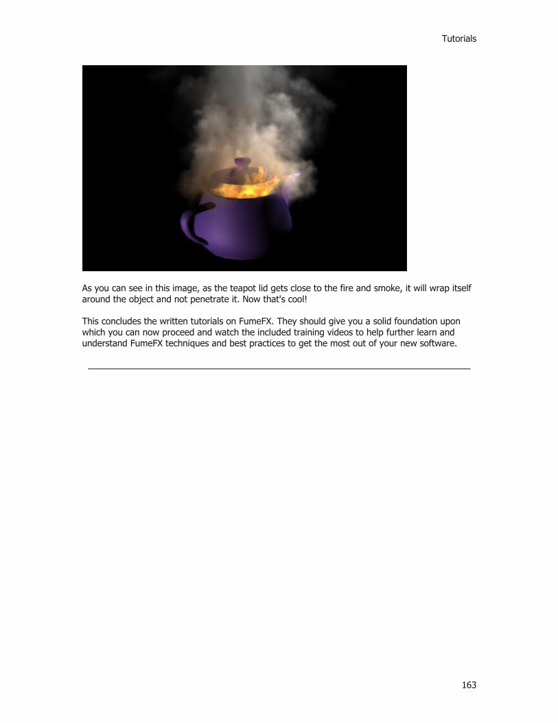
Tutorials
163
As you can see in this image, as the teapot lid gets close to the fire and smoke, it will wrap itself around the object and not penetrate it. Now that's cool! This concludes the written tutorials on FumeFX. They should give you a solid foundation upon which you can now proceed and watch the included training videos to help further learn and understand FumeFX techniques and best practices to get the most out of your new software.

165
Index 3 3ds Max Script 34 6 64-bit 8 A Ability to Stop/Continue 98 About FumeFX 19, 25 Absolute Age 89 Active 56, 66, 72, 76, 80 Adaptive 19, 25, 34 Adaptive Grid Practices 114 Add 66, 80 Add Values to the Voxel 56, 66, 72, 76, 80 Advection Stride 38 AFC 44, 116 AFC Controller 66, 80 Affect Orientation checkbox 89 Affect Position 89 Alpha Multiplier 42, 44 Ambient Color 44, 48 Amount 56, 66, 72, 76, 80 Animation Flow Curves 116 Authorization 16 Automatic 19, 25 B Bezier 116 Birth Operator 95 Blocking Sides 38 Buoyancy 38 Burn Rate 38 Burn Rate Variation 38 By Volume 89 C Cache Map To Disk 50 Calculate Interval 31 Cast Shadows 44, 48 Channel 19, 25, 48 Channel Data 48 Channel Data Shader 48 Channel is Disabled 56, 66, 72, 76, 80 Channel values 95 Channel/Threshold 19, 25 Channels 89 Clear Cache 50 Clear RAM After Simulation 98 Color 44 Color – Spinner 42 Color – Swatch/Gradient 42 Color Gradient 44, 48 Container Edges 42 Continue 31 Copy 116
Corner 116 Cubic interpolation 38 Cycle 34 D Default Output Path 98 Delete 116 Delete Particles 89 Delete Snapshots on Scene Exit 98 Detail 38 Diffusion 38 Dimension Parameters 56, 72 Directional 56, 72 Disabled 76 Display Optimize 19, 25 Dissipation Min. Dens 38 Dissipation Strength 38 Dynamics Status 86 E Effects Channel 42 Emit Start 89 Emit Stop 89 Enable Display 19, 25 End Frame 34 Event Age 89 Every Nth frame 98 Expansion 38 Export Channels 34 Exporting Channels 34 Expression 84 Extra 76 F Falloff 50 Falloff Type 42 Fire 19, 25, 44, 89 Fire multiplier 50 Fire Strength 50 Flags 89 Follow Operator 95 Force 19, 25, 53 Forces 19, 25 fR GI multiplier 42, 44, 48 Frames 38, 56, 72, 76, 98 Free Flow 72, 76 Free Flow checkbox 56 Fuel 19, 25, 38, 44, 56, 66, 72, 76, 80, 89 Fuel Creates Smoke 38 FumeFX
Fire 103 FumeFX Birth Operator 89 FumeFX Dynamics Status Window 86 FumeFX Floater 31 FumeFX Follow Operator 89
Printed Documentation
166
FumeFX Gravity Vector 53 FumeFX Grid 19, 25 FumeFX Object Source 53, 76 FumeFX Particle Source 53, 80 FumeFX Simple Source 53 FumeFX Smoke 103 FumeFX Source Controllers 84 FumeFX Test 89 FumeFX UI 19, 25 Functions Exposed by FumeFX 104 FusionWorks Z Depth 103 G General 98 General Parameters 19, 25, 34 Global Parameters 98 Gradient Controls 116 Gradient Usage 116 Gravity 38 Grid 19, 25 H Heat production 38 Height 19, 25, 34 I Icon Size 66, 76, 80 If Out Of Grid 89 Ignition Temperature 38 Illumination 50 Illumination Map 50 Illumination Parameters 50 In Contact With Object 89 Influence % 95 Inherit From FumeFX 89, 95 Installation 16 Invert 89 J Jitter % 89 Jittering 50 Jittering % 42 K Keyless mode 116 L Length 19, 25, 34 Light Tracer 114 Lights 50 Linear 116 Load 116 Load settings 31 M Map 42, 44, 48, 56, 72, 76 Map Channel 76 Map Source 42, 44, 48 Max Ang. Vel 89 Max. 19, 25, 103 Max. Density 44
Max. Value 48 Maximum 89 Maximum Depth 50 Maximum Influence 84 Maximum Stride 38 MAXScript 104 Min. 19, 25, 103 Min. Density 44 Min. Value 48 Minimum 89 Minimum Influence 84 Multiple Scattering 50 Multiplier 50 Multithreading 98 N New 89 Next to Object 89 None 19, 25, 34, 98 Numerical Values 19, 25 O Object 89 Object Distance 84 Object Source 76 Object Source Parameters 61 Object’s 56, 72, 76 Objects / Sources 114 Objects / Sources Workflows 114 Opacity 44 Opacity – Spinner 42 Opacity AFC 48 Operators 89 Out Of Grid 95 Out-of-Range Types 34 Output Path 34, 98 Output Rollout 34 P Parameters 80 Particle 80 Particle Age 89 Particle Flow 89 Particle Flow Operators 89 Particle Source 80 Particle Source Parameters 66 Paste 116 Path 98 Path Options 98 Pick / Remove 66, 76, 80, 89 PingPong 34 Play From 34 Play To 34 Playback 34 Point in Grid (bool) 95 Position 19, 25

Index
167
Post Load 42 Preferences 19, 25, 98 Preview 19, 25, 31 Preview Window 86 Probe Operator 95 Q Quality 38 R Radial 56, 72 Radio Button 95 Radius 66, 80 Rate 89 Receive Shadows 44, 48 Reduce 19, 25 Render Elements 103 Rendering Parameters 42 Reset 116 S Save 116 Save settings 31 Scale 38, 56, 72, 76 Scale Multiplier 19, 25 Scratch Disk 98 Seed 66, 80, 89 Sensitivity 19, 25, 34 Set 56, 72 Set Values in the Voxel 56, 66, 72, 76, 80 Shader 42 Shadow Falloff 44, 48 Shadows 50 Shape 56, 72 Shell 56, 72 Show Slice 19, 25 Simple Source 72 Simulation 31, 38 Simulation Area 19, 25 Simulation Steps 38 Smoke 19, 25, 38, 44, 56, 66, 72, 76, 80, 89 Smoke Density 38 Smoke Strength 50 Smooth 116 Snapshot 98 Snapshot Options 98 Soften Edges Near Objects 42 Solid 56, 72 Solver 38 Solver Maximum Iterations 38 Source 56, 72, 84, 89 Source controller 56, 66, 72, 76, 80 Source Controllers 84 Spacing 19, 25, 34 Speed Multiplier 89 Speed Variation 89
Standard Shader 44 Start 31 Start Frame 34 Start Simulation 31 Start Simulation with Loaded Initial State 31 Step Size 50 Step Size % 42 Step Size In Fire % 42 Strength 42 Subframe Sampling 89 Swap to Disk if Out of RAM 98 Sync By T TCB 116 Technical Support 16 Temperature 19, 25, 38, 56, 66, 72, 76, 80,
89 Test Operator 95 Thickness 19, 25 Thinking Particles 95 Thinking Particles Operators 95 Threads 98 Threshold 19, 25 Threshold Scale 19, 25 Time Scale 38 Tips and Tricks 114 Turbulence 19, 25, 56, 72, 76 Turbulence amounts 38 Turbulence Noise 38 Type 56, 66, 72, 76, 80 U Undersample/Threshold 50 Uniqueness 89 Use 34 Use all available CPU's 98 V Var. % 66, 80 Variation 89 Velocities 19, 25 Velocity 19, 25, 56, 72, 76, 89 Velocity Damping 38 Velocity Magnitude 89 Velocity Multipier 89 Velocity Multiplier 66, 80, 89 Viewport 19, 25 Viewport Update 34 Visual Falloff 44, 48 Volume 56, 72 Volume Shading 42 Vorticity 38, 89 Voxel Fuel 84 Voxel Grid 19, 25 Voxel Smoke 84

Printed Documentation
168
Voxel Temperature 84 W Width 19, 25, 34
X X/Y/Z Turbulence 38 XY plane 19, 25


