
Fully-Online, Multi-Command Brain Computer Interface … · Interface with Visual Neurofeedback...
28
Fully-Online, Multi-Command Brain Computer Interface with Visual Neurofeedback Using SSVEP Paradigm Pablo Martinez, Hovagim Bakardjian and Andrzej Cichocki Laboratory for Advanced Brain Signal Processing, RIKEN Brain Science Institute Abstract: We propose a new multi-stage procedure for a real time brain machine/computer interface (BCI). The developed system allows a BCI user to navigate a small car (or any other object) on the computer screen in real time, in any of the four directions and to stop it if necessary. Extensive experiments with 5 young healthy subjects confirmed the high performance of the proposed on-line BCI system. The modular structure, high speed and the optimal frequency-band characteristics of the BCI platform are features which allow an extension to a substantially higher number of commands in the near future. Indexing terms: Brain Computer Interface (BCI), Real-time signal processing and neural computation, Steady State Visual Evoked Potentials (SSVEP), Blind Source Separation (BSS).
Transcript of Fully-Online, Multi-Command Brain Computer Interface … · Interface with Visual Neurofeedback...

Fully-Online, Multi-Command Brain Computer
Interface with Visual Neurofeedback Using
SSVEP Paradigm
Pablo Martinez, Hovagim Bakardjian and Andrzej Cichocki
Laboratory for Advanced Brain Signal Processing,
RIKEN Brain Science Institute
Abstract:
We propose a new multi-stage procedure for a real time brain machine/computer
interface (BCI). The developed system allows a BCI user to navigate a small car
(or any other object) on the computer screen in real time, in any of the four
directions and to stop it if necessary. Extensive experiments with 5 young
healthy subjects confirmed the high performance of the proposed on-line BCI
system. The modular structure, high speed and the optimal frequency-band
characteristics of the BCI platform are features which allow an extension to a
substantially higher number of commands in the near future.
Indexing terms: Brain Computer Interface (BCI), Real-time signal processing
and neural computation, Steady State Visual Evoked Potentials (SSVEP), Blind
Source Separation (BSS).

1. Introduction
A brain-computer interface (BCI), or a brain-machine interface (BMI), is a
system that acquires and analyzes brain signals to create a high-bandwidth
communication channel in real-time between the human brain and the computer
or machine [1-5]. In other words, brain computer interfaces (BCI), are systems
that use brain activity (as reflected by electric, magnetic or metabolic signals) to
control external devices such as computers, switches, wheelchairs, or
neuroprosthetic extensions [6-12]. While BCI research hopes to create new
communication channels for disabled or elderly persons using their brain signals
[1,2], recently efforts has been focused on developing potential applications in
rehabilitation, multimedia communication and relaxation (such as immersive
virtual reality control) [17-18] . Today, BCI research is an interdisciplinary
endeavor involving neuroscience, engineering, signal processing and clinical
rehabilitation, and lies at the intersection of several emerging technologies such
as Machine Learning (ML) and Artificial Intelligence (AI) among others. BCI is
considered as a new frontier in science and technology, especially in multimedia
communication [1-18].
The various BCI systems use different methods to extract the user’s intentions
from her/his brain electrical activity, for example:
(i) Measuring the brain activity over the primary motor cortex that results
from imaginary limbs and tongue movements [3,5],

(ii) Detecting the presence of EEG periodic waveforms, called steady-
state visual evoked potentials (SSVEP), elicited by multiple flashing
light sources (e.g., LEDs or phase-reversing checkerboards) [6-18],
(iii) Identifying characteristic event related potentials (ERP) in EEG that
follow an event noticed by the user (or his/her intention), e.g., P300
peak waveforms after a flash of a character the user focused attention
on [1-3].
In the first approach, the usually exploited features of the brain signals are their
temporal/spatial changes and/or the spectral characteristics of the SMR
(sensorimotor rhythm) oscillations, or the mu-rhythm (8-12 Hz), and the beta
rhythm (18-25 Hz). These oscillations typically decrease during movement or
when preparing for movement (event related desynchronization, ERD) and
increase after movement and in relaxation (event-related synchronization, ERS).
ERD and ERS help identify those EEG features associated with the task of motor
imagery EEG classification [3, 5]
While the first example (i) relies on imaginary actions to activate the
corresponding parts of the motor cortex, the second (ii) and third (iii) examples
involve actual selective stimulation in order to increase the information transfer
bit rates [3].
Steady-State Visual Evoked Potentials are the elicited exogenous responses of
the brain under visual stimulations at specific frequencies. Repetitive stimulation

evokes responses of constant amplitude and frequency. Each potential overlaps
another so that no individual response can be related to any particular stimulus
cycle. It is presumed therefore that the brain has achieved a steady-state of
excitability [20].
Applications of SSVEP on BCI were proposed by Middendorf et al. [6] and
applied later by other groups [7-19]. Previously cited methods, except the
approach by Materka and Byczuk [10], have in common that are based on
spectrum techniques for feature extraction, and all have the sources of the stimuli
(flickering patterns, LED…) in a fixed position.
Comparing to previous SSVEP-BCI, our system is based mainly on the temporal
domain: combining of a Blind Source Separation (BSS) algorithm for artifact
rejection and tuned micro-batch-filtering to estimate the features to be used with
a classifier in our case a fuzzy neural network classifier.
Also, in our design the sources of stimulus are moving (adding extra complexity),
and we have shown that it is possible to perform a robust BCI also for moving
flickering targets.
In general, the SSVEP-BCI paradigm has the following potential advantages and
perspectives:
1. It offers the possibility of high performance (information rate) with
minimal training time and low requirements form the subject.

2 The carefully designed SSVEP-BCI system can be relatively robust in
respect to noise and artifacts. Artifacts may cause performance degradation;
however they can be removed or reduced using advanced signal processing
techniques like BSS. Also blink movement and electrocardiographic
artifacts are confined to much lower frequencies and do not make serious
problem to accurate feature extraction.
3. SSVEP-BCI systems are relatively easy to extend to more commands.
4. Usually BCI systems have higher information transfer rates.
5. Short training phase is required and application almost does not require
special training.
However, SSVEP-BCI may have also some disadvantages:
1 The flickering visual stimuli visual may cause some fatigue or tiredness if
subject use it for a long time. This fatigue is cause from the stimulation
while other BCI systems as P300 can cause fatigue due to the required
concentration, while SSVEP does not.
2. The flickering stimuli at some frequencies, patterns, colors, etc. may not
be appropriate for subjects with photo-sensitive neurological disorders
3. SSVEP-based BCIs depend on muscular control of gaze direction for
their operation, whereas other kinds of BCI systems do not depend on the
brain’s normal output pathways of peripheral nerves and muscles. Due to
this reason this paradigm may not work for some seriously disable patients.

In other words, evoked potentials, especially SSVEP, require stable control
of the eye muscles so that such an approach may not be applicable to all
users.
In this paper we present a BCI platform based on the SSVEP paradigm.
Although the SSVEP paradigm has been exploited in a number of studies [4, 6-
19], our design of experiments and signal preprocessing and classification tools
are innovative and moreover, they are suitable for real-time applications with
visual neurofeedback.
2. BCI System Based on SSVEP Paradigm: Design and Implementation
2.1 Stimulator design
In this paper we present a new BCI system with a visual stimulation unit
designed as a smart multiple choice table in the form of an array of four small
checkerboard images flickering with different frequencies and moving along
with the controlled object (see Fig.1). When a BCI user focuses his/her attention
or gazes on a specific flickering image, a corresponding periodic component
(SSVEP) can be observed in the EEG signals notably over the occipital (visual)
cortex [20],

Fig. 1 Four small checkerboards flickering at different but fixed frequencies move along with a navigated car. The subject is able to control the direction of movement of the car by focusing her/his attention on a specific checkerboard. Two sets of flickering frequencies were used: (i) Low-frequency range {UP: 5 Hz, LEFT: 6 Hz, DOWN: 7 Hz, RIGHT: 8 Hz} and (ii) Medium-frequency range {UP: 12 Hz, LEFT: 13.3Hz, DOWN: 15Hz, RIGHT: 17Hz}
When a BCI user focuses his/her attention or gaze on a specific flickering image,
its corresponding weak quasi-periodic component (SSVEP) is elicited mainly
over the occipital (visual) cortex.[20]. In addition, they are buried in a large noise
and therefore it is a challenge to extract them reliably in real-time. For this
purpose, we developed and applied multi-stage online (real-time) signals
processing tools described in detail below.
a. Analysis system overview
The signal analysis unit of our BCI system consists (see Fig. 2) of a data
acquisition module, an enhanced signal pre-processing unit including online
blind-source separation (BSS) for artifact rejection and noise reduction, a bank of

narrow band-pass filters, a multiple-feature extraction system with Savitzky-
Golay (S-G) smoothing, energy normalization and an Adaptive-Network Fuzzy
Inference System (ANFIS)[28].
S-GS-GFeature Extraction(Power Band…)
FeatureExtraction
(Energy)ANFIS
COMMAND OUTPUT
COMMAND OUTPUT
XXBSS
Bank of FiltersBank of Filters
N :Number of electrodes(6)M :Number of bands(4)
nEEG
n .n x m .n x m mS-GS-GS-GS-GFeature Extraction(Power Band…)
FeatureExtraction
(Energy)
Feature Extraction(Power Band…)
FeatureExtraction
(Energy)ANFISANFIS
COMMAND OUTPUT
COMMAND OUTPUT
XXXXBSS
Bank of FiltersBank of FiltersBank of FiltersBank of Filters
N :Number of electrodes(6)M :Number of bands(4)
nEEG
n .n x m .n x m m
Fig. 2 Conceptual scheme of the proposed real –time BCI system. The system consists of a BSS (Blind Source Separation) module for automatic rejection of artifacts and noise, a bank of (narrow band pass) filters to enhance the first harmonics of the SSVEP responses, a Feature Extraction block with S-G (Sawitzky-Golay) smoothing and energy normalization and ANFIS (Adaptive-Network Fuzzy Inference System) for a final classification.
To perform all signal processing tasks in real time, the analysis unit was
implemented in Labview® and C/C++, while the stimulation unit was based on
speed-optimized Matlab code.
A general platform overview of our BCI system is shown in Fig.3.
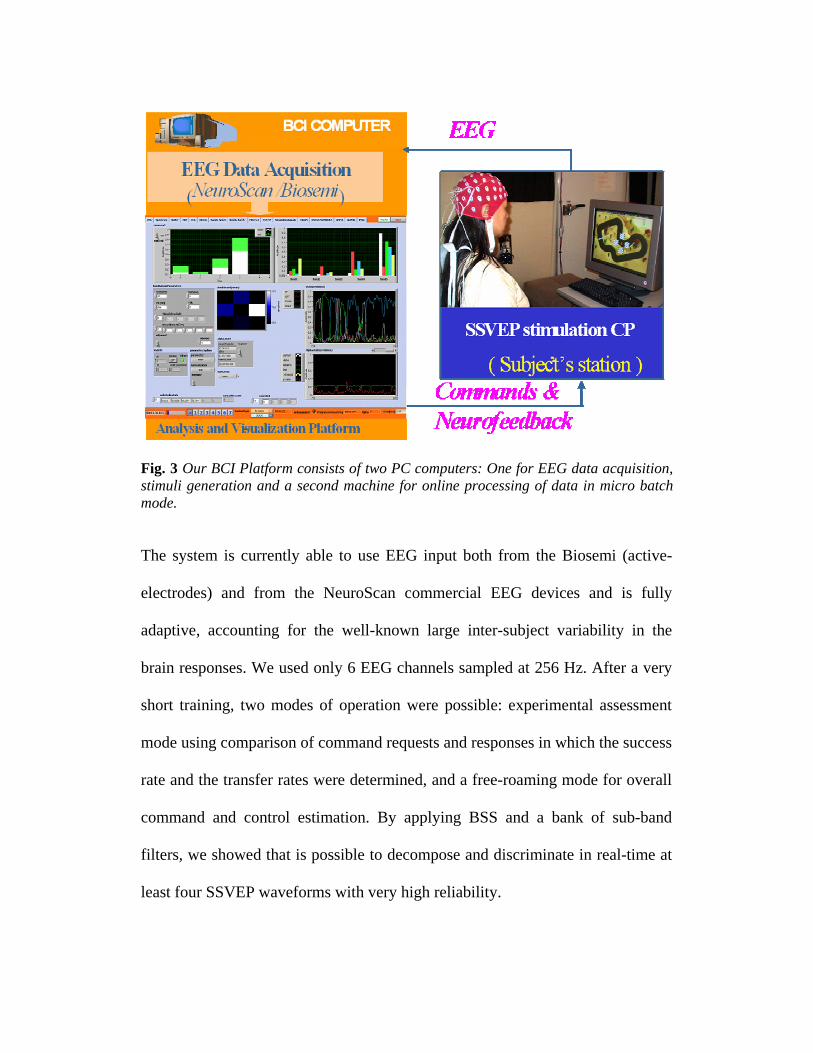
Fig. 3 Our BCI Platform consists of two PC computers: One for EEG data acquisition, stimuli generation and a second machine for online processing of data in micro batch mode. The system is currently able to use EEG input both from the Biosemi (active-
electrodes) and from the NeuroScan commercial EEG devices and is fully
adaptive, accounting for the well-known large inter-subject variability in the
brain responses. We used only 6 EEG channels sampled at 256 Hz. After a very
short training, two modes of operation were possible: experimental assessment
mode using comparison of command requests and responses in which the success
rate and the transfer rates were determined, and a free-roaming mode for overall
command and control estimation. By applying BSS and a bank of sub-band
filters, we showed that is possible to decompose and discriminate in real-time at
least four SSVEP waveforms with very high reliability.

In this study we applied a set of five electrodes placed over the occipital area
{CPZ, PZ, POZ, P1, P2} and one electrode placed over the frontal cortex {FZ},
as illustrated in Fig. 4 (left).
Occipital electrode configuration
Occipital electrode configuration
Fig. 4 Electrode configuration. 5 electrodes placed over the occipital area {CPZ, PZ, POZ, P1, P2} and one over the frontal cortex {FZ}.
2.3 Artifact rejection by blind source separation
A second-order Blind Source Separation (BSS) algorithm was applied to enhance
the signal and to attenuate artifacts [26]. It was characterized by a continuous
working system in micro-batch mode with sliding time window of 4 seconds and
with a discrete time shifts of 120 milliseconds. This means that the system was
able to refresh the incoming data every 120 ms and to take into account the EEG
signals from the last 4s. The presence of artifacts, especially eye movement
related artifacts, can decrease the performance of the system substantially. In the
case of SSVEP stimulation and analysis, their very specific response frequencies

(corresponding to the observed pattern flicker frequencies) could be erroneously
detected in the presence of artifacts if online BSS is not applied.
For the BSS procedure, we applied a modified and improved real-time AMUSE
algorithm with a time sliding windows, since such an algorithm allows a very fast
(few milliseconds) and reliable estimate of the independent components with
automatic ranking (sorting) according to their increasing frequency contents
and/or decreased linear predictability. The implemented BSS-AMUSE algorithm
can be considered as consisting of two consecutive PCA (principal component
analysis) blocks: First, PCA is applied to the input data; and then a second PCA
(SVD) is applied to the time-delayed covariance matrix (in our case the delay is
set to one sample or 4 ms) of the output from the previous stage. In the first step
standard or robust pre-whitening (sphering) is applied as a linear transformation
[26]
( ) ( )t t=z Qx (1)
where 12
x−=Q R of the standard covariance matrix
( ) ( ){ }Tx t t=R x xE (2)
and ( )tx is a vector of observed data for time instant t. Next, SVD is applied to a
time-delayed covariance matrix of pre-whitened data:
( ) ( ){ }1T Tz t t= − =R z z USVE , (3)
where S is a diagonal matrix with decreasing singular values and U, V are
matrices of eigenvectors. Then, an unmixing (separating) matrix is estimated as
1ˆ T−= =W A U Q (4)
The estimated independent components are obtained as
=Y WX (5)
where X = [x(1),x(2), …,x(N)]
1x
Wn
y��
mx̂
mx
2x
1y
2y 2x̂
1x̂
�
W
SensorSignals
DemixingSystem
BSS/ICA
InverseSystem
ReconstructedSensorsSignals
ExpertDecision
�
Hardswitches
0 or 1
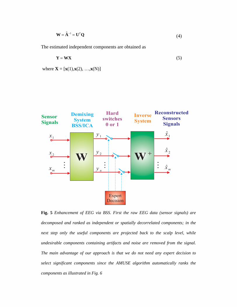
Fig. 5 Enhancement of EEG via BSS. First the raw EEG data (sensor signals) are
decomposed and ranked as independent or spatially decorrelated components; in the
next step only the useful components are projected back to the scalp level, while
undesirable components containing artifacts and noise are removed from the signal.
The main advantage of our approach is that we do not need any expert decision to
select significant components since the AMUSE algorithm automatically ranks the
components as illustrated in Fig. 6

The AMUSE BSS algorithm allowed us to automatically rank the EEG
components. The undesired components corresponding to artifacts were removed
and the rest of the useful (significant) components were projected back to scalp
level using the pseudo inverse of W.
ˆ = +X W X (6)
The 6 EEG channels were high pass filtered with a cutoff frequency of 2 Hz
before the AMUSE algorithm was applied.
Fig. 6 Illustration of the on-line preprocessing module – artifact rejection: actual EEG
data (left), estimated automatically-ranked independent components - the first and the
last components were rejected as artifacts (center), back-projected (enhanced) EEG
signals (right) which serve as the input for the bank of band-pass filters.(4 seconds
window)

The rejection of the first and the last components had two implications: (1) the
EEG signal was enhanced as some oscillations were removed which were due to
ocular and other artifacts but included frequencies similar to the target flicker
responses. Without this procedure the performance of the system would have
deteriorated substantially since blinking could not be avoided by the
experimental subjects; (2) at the same time we ensured that the control of the car
in our BCI system was strictly due to the SSVEP responses elicited by the cortex,
and not simply due to eye movements.
2.4 Bank of band pass filters and features extractions
We designed a bank of third-order elliptic IIR (Infinite Impulse Response) filters
with bandwidth 0.5 Hz and with center frequencies corresponding to the
flickering frequencies of the checkerboards. The fundamental frequencies of the
SSVEP responses were detected by estimating the power of the output signals of
the filters. We should mention here that using another type of filters could also be
appropriate, under the assumption that the overlap of the bandwidths of the sub-
bands would be small enough. As we were interested only in the power of signals,
their phase had no relevance in this case.

Four time series representing the fluctuations of the energies over time were
obtained and subsequently smoothed by means of a Savitzky-Golay(S-G) filter
[27]
Instead of smoothing each time series’ power contents in each sub-band with a
standard Moving Average (MA) filter, we propose using a Savitzky-Golay filter
with a second-order polynomial smoothing. The main advantage of this approach
is that it tends to preserve fundamental features such as relative maxima, minima
and width of the peaks, which are usually distorted by other filtering methods,
like MA. The S-G smoother approximates the time series within the moving
average window not by a constant (estimate of which is the average, as in MA),
but by a polynomial of higher order. In other words, this method essentially
performs a local polynomial regression (of degree M=2) on a distribution, of at
least k=nR+nL+1 points, to determine the smoothed value for each point.
The general mathematical expression of the Savitzky-Golay smoothing filter can
be described as follows.
[ ] [ ]nR
nk nL
y n c x n k=−
= +∑ (7)
1
0 0,
( )M
T mn
m m
c A A n−
=
⎡ ⎤= ⎣ ⎦∑ (8)
Where
,..., 0,...,jijA i i nL nR j M= = − = (9)

The signal is smoothed by nL points before, and by nR points after each
considered time point - according to equation (7), where the weighting
coefficients cn are obtained by means of equation (8). If the filter is casual then
nR = 0. We set nR>0 to enhance the smoothing although it introduced a small
delay. For online purposes nR<<nL. A moving average filter MA is a S-G filter
with M = 0.
In figure 7, it is shown as an example the performance of the S-G filter compared
with a Moving average filter for a simulated signal with added noise.
Fig. 7.Simulated data was used in this example to show a comparison of (a) Moving average smoothing (nR=30, nL=5) vs.(b) a S-G filter (nR=30, nL=5, order 2). MA is not able to track short time changes having high time response. S-G moving average has similar noise cancellation but better track of changes. In BCI it is important to find a good balance between enhanced smoothing and at the same time to be able to follow fast changes in the signal. The S-G was applied separately for each band pass filter and electrode.
After S-G filtering we performed also a standard normalization of the smoothed
energy as follows

Nje
eE N
j
M
iij
M
iij
j ..1 1..M i
1 1
1 ===
∑∑
∑
= =
= (10),
where M is the number of the electrodes, N is the number of the band pass filters
and eij is the estimated energy of electrode i and band pass filter j.
11
=∑=
M
jjE
(11)
As the stimulation frequencies are close to each other no need of compensation is
need it for each frequency. In case of using more frequencies it is better to send
to the classifier normalized values, although this is not the case in this paper.
Therefore Ej was the relative energy per band and these energy values were used
as input parameters for the ANFIS classifier, see Fig. 8.
(a)
L U L D U R L D U R
U = up L = left D = down R = right
Eval. Mode: Request

(b) Fig. 8 Normalized multi-band signals Ej during evaluation mode: (a) A good example case with one of the subjects, and (b) A suboptimal example in another subject where ANFIS was essential in enhancing the final performance of the system.
2.5 ANFIS Classifier
One of the most complicated problems with the BCI systems is the classification
of very noisy EEG signals. For this purpose we have applied an adaptive,
subject-specific classifier to recognize different SSVEPs.
The standard Adaptive Network Based Fuzzy Inference System (ANFIS)
architecture network was used. This system consists of a Fuzzy Inference System
(FIS) whose membership function parameters are tuned (adjusted) using a back
propagation algorithm alone in combination with a least squares type of method
(Jang, 1993) [28]. Using a hybrid learning procedure, the ANFIS can learn an
input-output mapping based on some a priori knowledge (in the form of if-then
fuzzy rules).
R U R D U L D U R LL
U = up L = left D = down R = right
Eval. Mode: Request

The applied ANFIS has four inputs consisted in a Sugeno type FIS with two
Membership functions (generalized bell function) per input and the output as a
constant membership function [28]
21( | , , )
| |1bf x a b c
x ca
=−⎛ ⎞+⎜ ⎟
⎝ ⎠ (12)
Four features of EEG signals were used as input patterns (normalized energy
values) for the ANFIS system, corresponding to each checkerboard.
3. Operating Modes
To overcome the problem of the inter-subject variability, some short-term
preparatory activities were necessary for the BCI system before the final real-
time practical evaluations or applications could be initiated. For this purpose, our
BCI system was implemented to work in three separate modes:
• Training mode.
• Evaluation (testing) mode.
• Free racing (unsupervised) mode.
The training- and if necessary the evaluation modes allowed us to find the
optimal parameters for each specific subject. In that way, these parameters could
be used later in the free-racing (unsupervised mode).

3.1 Training Mode
In order to train the classifier the computer requested the subject to fix their
attention on each checkerboard {UP, LEFT, RIGHT, LEFT} during time
intervals of 6-s duration each, using voice-message requests. These requests to
execute specific directions were presented in random order.
A fifth, additional, request required no stimulus and involved removing all
checkerboard patterns from the screen during the 6 s interval to measure the
control non-SSVEP responses.
The corresponding values of the normalized energies were extracted for each
command in the time interval between 3 and 6 seconds after each command
request. In this time interval it was considered that the subject was reaching a
stable steady-state for each corresponding event.
During the training mode the neurofeedback was disconnected and the car was
fixed in the center of the screen to facilitate the subject to focus her/his attention
to each flickering checkerboard board.
3.2 Evaluation Mode
After the training, we asked the subject first to move the car as its own in order
to confirm that he or she had the full ability to control the car in any direction.
Then, to evaluate the BCI performance for this subject, including time responses
and percentage of success (see results bellow), the computer generated in random

order requests for movement in each direction using voice messages, similarly to
the training mode. The subject was requested to move the car in one of the 4
directions at intervals of 9 s in 32 trials (8 trials per direction). It was assumed
that the subject successfully performed a task if she/he moved the car properly in
a time window between 1 second and up to a maximum of 6 seconds after the
onset of the voice-request command. During the evaluation mode the
neurofeedback was fully enabled and the car was able to move freely, responding
to the subject’s commands.
3.3. Free race (unsupervised) mode In this mode the user could move the car freely within the racing course (Fig. 1),
and we asked all the subjects to complete at least one lap to evaluate their overall
control of the car by performing this task without any external voice commands.
This typically took to each subject between 90 to 150 seconds to achieve this
complex goal, also depending on the flicker frequency range.
4. Experimental Setting and Results We tested our SSVEP-based BCI system with 5 subjects (two female and 3 male)
and for two different ranges of flicker frequencies: Low-Frequency (LF) range -
5,6,7,8 Hz and Medium-Frequency (MF) range - 12, 13.3, 15, 17 Hz.
The subjects sat on a chair approximately 90 cm from the center of a 21-inch
cathode-ray tube (CRT) monitor screen using a refresh rate of 120 Hz.

Six electrodes were used: five placed over the occipital cortex {CPZ, PZ, POZ,
P1, P2} and one over the frontal cortex {Fz}, see Fig. 2.
The performance of the BCI system was measured during the evaluation mode,
as described in the previous section.
Table 1. Experimental results for Occipital configuration(Mean values). Subject #1 #2 #3 #4 #5
LF (5 – 8 Hz) Success (%) 100 77.5 94.8 92.3 100
Delay Time[s] 3.6 ± 0.4 3.8 ± 1.7 3.3 ± 1 3.3 ± 1.1 4.8 ± 1 MF (12 – 17 Hz)
Success (%) 100 100 100 100 82.3 Delay Time [s] 3.6 ± 0.3 3.9 ± 0.8 3.2 ± 0.4 3.1 ± 1.1 3.7 ± 1.3
The results are shown in Table 1 (subject-specific results) and Table 2 (mean
results). The data obtained in this study indicated that the performance for the
medium-frequency range flicker was slightly higher when compared to the low-
frequency range flicker responses, in terms of controllability of the car and
execution time delay.
Table 2. Experimental results for Occipital configuration (Mean values and mean bit rate).
Flicker Range
(Frequency)
LF
(5 – 8 Hz)
MF
(12 – 17 Hz)
Success Rate 93 % 96.5 %
Execution Delay 3.7 ± 1.0 s 3.5 ± 0.8 s
Bit rate 26 bits/min 30 bits/min
Only one of the subjects was more comfortable with, and felt that his car control
was better when using the low-frequency–range flicker.

The subjects performed the BCI experiments just a single time for each
frequency range (LF, MF), including classifier training and evaluation (results)
modes. After the experiment each subject was asked to demonstrate her/his
overall control of the car for each frequency range by completing a full lap as
quickly as possible in free racing mode.
5. Conclusion and Discussions
Although the SSVEP paradigm is well known in the BCI community since the
studies performed by several research groups [6-19], especially Shangkai Gao
group at Tshinghua University [8,9,10,16] and NASA research group of Trejo et
al[7], we believe that our system offers several novel points for improved
usability and efficiency, such as the integrated moving checkerboards patterns to
maximize selective attention and to minimize eye movements in respect to the
controlled target, as well as an online BSS module to reduce automatically
artifacts and noise, improved feature selection algorithm with efficient smoothing
and filtering and an adaptive fuzzy neural network classifier ANFIS. All of our
EEG signal processing modules and algorithms are carefully optimized to work
on-line in real time. This proposed method and BCI platform could be easily
extended for various BCI paradigms, as well as for other types of brain analysis
in which real-time processing and dynamic visualization of features are crucial.
Paradigms based on steady-state visual and other evoked potentials are among
the most reliable modes of communication for implementation of a fast

noninvasive EEG BCI system that can discriminate in near real time a very high
number of unique commands or symbols. The capability of a BCI system to issue
more commands in a more reliable way has significant advantages such as
allowing better control of semi-autonomous remote navigation devices in
hazardous environments, or navigating precisely a cursor on a computer screen
(or the realization of a virtual joystick). However, in our experimental design we
have incorporated a number of original elements and ideas as compared to the
typical SSVEP paradigm. In addition to our new dynamic visual stimulation
approach, we have developed and implemented novel and efficient real-time
signal preprocessing tools and feature extraction algorithms. Although using our
dynamic pattern movement design may require some eye movement control by
the subjects, as well as sustained short-term attention, the control of the object
(car) could be easily changed to static for completely disabled subjects.
According to our tests and to previous reports Mueller and Hilvard [24] and
Kelly et al [9]), eye movement could be avoided altogether in SSVEP (possibly
at some performance cost) so that selective attention (with a fixed gaze between
the flicker patterns) could be used for flicker response gating / enhancement
corresponding to the requested commands.
The ability of our SSVEP BCI system to operate not only in the medium
frequency flicker range, but also in the low frequency range, shows its
advantages in comparison to the traditionally-used FFT-based methods, which
usually require the usage of the higher harmonics when the visual stimulation is

in the low frequency range. In contrast, our algorithm estimates the normalized
energy of each flickering frequency directly by using a dedicated tuned filter,
allowing us to discriminate easily between a stimulation-driven frequency and its
higher harmonics. In multiple-command BCI experimental designs, the flickering
pattern frequencies could be set to be very close and limited by the minimal
overlapping band-passes of the applied filters under the physiological constraints
of discerning between cortical responses to two close stimulation frequencies.
In summary, we successfully demonstrated the application of a fast online BSS
algorithm for automatic rejection of artifacts and noise reduction, a bank of band-
pass filters with non-stationary smoothing, and an adaptive fuzzy classifier.
6. References
1. Birmbaumer N., Kubler A., Ghanayim N., Hinterberger T., Perelmouter J., Kaiser J., Iversen I., Kotchoubey B., Neumann N., and Flor H.: “The Thought Translation Device for Completely Paralysed Patients”, IEEE Transactions on Rehabilitation Engineering, 8, 190-193, 2000.
2. Wolpaw J., Birmbaumer N., McFarland D., Pfurtscheller G., Vaughan T.: “Brain computer interfaces for communication and control”, Clinical Neurophysiology, 113, 767-791, 2002.
3. Pfurtscheller G., Neuper C., Guger C., Harkam W., Ramoser H., Schlögl A., Obermaier B., and Pregenzer M.:. “Current trends in Graz brain-computer Interface (BCI) research”, IEEE Transactions on Rehabilitation Engineering, 8, (2), 216-219, 2000.
4. Mueller-Putz G., Scherer G., Brauneis R.C. , and Pfurtscheller G.,: “Steady state visual evoked potential (SSVEP)-based communication: impact of harmonic frequency components,” J. Neural Eng., vol. 2, no. 4, pp. 123– 130, 2005.
5. Lee H, Cichocki A., and Choi S., "Nonnegative matrix factorization for motor imagery EEG classification", In Proc. Int’l Conf. Artificial Neural Networks (ICANN), Athens, Greece, Sept. 2006, Springer Lectures Notes in Computer Science, LNCS 4132, pp 250-259, 2006.

6. Middendorf, M., McMillan, G.R., Calhoun, G. L., and Jones, K. S.: "Brain-computer interfaces based on the steady-state visual-evoked response." Neural Systems and Rehabilitation Engineering, IEEE Transactions on, Vol. 8, No. 2, pp. 211-214, 2000.
7. Trejo, L.J., Rosipal, R., and Matthews, B.: “Brain–Computer Interfaces for 1-D and 2-D Cursor Control: Designs Using Volitional Control of the EEG Spectrum or Steady-State Visual Evoked Potentials”, IEEE Transactions of Neural Systems and Rehabilitation Engineering, vol. 14, No 2, June 2006.
8. Cheng M., Gao X., Gao S., and Xu D.: "Design and implementation of a brain-computer interface with high transfer rates." Biomedical Engineering, IEEE Transactions on, Vol. 49, No. 10, pp. 1181-1186., 2002.
9. Kelly, S. P., Lalor, E., Finucane, C. McDarby, G., and Reilly, R. B., “Visual spatial attention tracking using high-density SSVEP data for independent brain-computer communication”, IEEE Trans. Rehabilitation. Eng., 2005, 13, (2), pp. 172–178.
10. Materka, A. and Byczuk, M.: “Using Comb Filter to Enhance SSVEP for BCI Applications” The 3rd International Conference on Advances in Medical, Signal and Information Processing (MEDSIP 2006) 17 – 19 July 2006, Glasgow, Scotland.
11. Lin, Z.; Zhang, C.; Wu, W.; Gao, X.;”Frequency Recognition Based on Canonical Correlation Analysis for SSVEP-Based BCIs”, Transactions IEEE on Biomedical Engineering, IEEE Volume 53, Issue 12, Part 2, Dec. 2006, Page(s):2610 – 2614.
12. Friman O. ; Volosyak I. ; Graser A. “Multiple Channel Detection of Steady-State Visual Evoked Potentials for Brain-Computer Interfaces”, IEEE Transactions on Biomedical Engineering : Accepted for publication Volume PP, Issue 99, 2006 (in print).
13. Yijun Wang; Ruiping Wang; Xiaorong Gao; Bo Hong; Shangkai Gao; A practical VEP-based brain-computer interface”, Neural Systems and Rehabilitation Engineering, IEEE Transactions on [see also IEEE Trans. on Rehabilitation Engineering], Volume 14, Issue 2, June 2006 Page(s):234 – 240.
14. Nielsen, K.D.; Cabrera, A.F.; Omar Feix do Nascimento; “EEG based BCI-towards a better control. Brain-computer interface research at Aalborg University”, Neural Systems and Rehabilitation Engineering, IEEE Transactions on [see also IEEE Trans. on Rehabilitation Engineering] Volume 14, Issue 2, June 2006 Page(s):202 – 204.
15. Jaganathan, V.; Mukesh, T.M.S.; Reddy, M.R.; “Design and implementation of High Performance Visual Stimulator for Brain Computer Interfaces”, Conference of the Engineering in Medicine and Biology Society, 2005. IEEE-EMBS 2005. 27th Annual International 01-04 Sept. 2005 Page(s):5381 – 5383.

16. Xiaorong Gao; Dingfeng Xu; Ming Chen; Shangkai Gao; “A BCI-based environmental controlled for motion-disabled.”, IEEE Transaction on Neural Systems and Rehabilitation Engineering, Vol.11, No.2, p137-140, 2003. (Special issue on Brain –Computer Interfaces)
17. E. C. Lalor, S. P. Kelly, C. Finucane, R. Burke, R. Smith, R. B. Reilly, and G..McDarby,"Steady-State VEP-Based Brain-Computer InterfaceControl in an Immersive 3D Gaming Environment", EURASIP Journal on Applied Signal Processing 2005:19, 3156–3164.
18. L. Piccini, S. Parini, L. Maggi and G. Andreoni: "A Wearable Home BCI system: preliminary results with SSVEPprotocol", Proceedings of the 2005 IEEE Engineering in Medicine and Biology 27th Annual Conference Shanghai, China, September 1-4, 2005, pp. 5384-5387.
19. F. Beverina, G. Palmas, S. Silvoni, F. Piccione,Silvio Giove: "User adaptive BCIs: "SSVEP and P300 based interfaces", PsychNology Journal, 2003 Volume 1, Number 4, 331 - 354
20. E. Niedermeyer; F.L Lopes da Silva “Electroencephalography: Basic Principles, Clinical Applications and Related Fields”, Chapter 54, 1982 Williams & Wilkings.
21. Davila, C.E.; Azmoodeh, M.;”Adaptive eigenfiltering of steady-state VEPs”, Engineering in Medicine and Biology Society, 1994. Engineering Advances: New Opportunities for Biomedical Engineers. Proceedings of the 16th Annual International Conference of the IEEE, 3-6 Nov. 1994, Page(s):207 - 208 vol.1.
22. Ruiping Wang; Xiaorong Gao; Shangkai Gao; “Frequency Selection for SSVEP-based Binocular Rivalry”, Conference Proceedings. 2nd International IEEE EMBS Conference on Neural Engineering, 2005., March 16-19, 2005 Page(s):600 – 603.
23. Jie Cui; Willy Wong; “The adaptive chirplet transform and visual evoked potentials”, IEEE Transactions on Biomedical Engineering, Volume 53, Issue 7, July Page(s):1378 – 1384, 2006.
24. Müller, M.M., Hillyard, S.: "Concurrent recording of steady-state and transient event-related potentials as indices of visual-spatial selective attention." Clinical Neurophysiology, Vol. 111, Issue 9, pp.1544-1552, 2000.
25. Burkitt, G.R., Silberstein, R.B., Cadusch, P.J., and Wood, A.W: "Steady-state visual evoked potentials and traveling waves." Clinical Neurophysiology, Vol. 111, Issue 2, pp. 246-258, 2000.
26. Cichocki A. and S.Amari S., Adaptive Blind Signal and Image Processing: Learning Algorithms and Applications, West Sussex, UK: John Wiley & Sons, 2003.
27. Savitzky A. and Golay Marcel J.E.: “Smoothing and Differentiation of Data by Simplified Least Squares Procedures”. Analytical Chemistry, 1964. 36: 1627-1639.

28. Jang, J.: “ANFIS: Adaptive-Network-based Fuzzy Inference systems”, IEEE
Transactions on Systems, Man, and Cybernetics, Vol. 23, No. 3, pp. 665-685, May 1993.


![Symbolic Verification of Message Passing Interface Programs · lems [11]. The Message Passing Interface (MPI) [78] is the current defacto standard programming paradigm for developing](https://static.fdocuments.us/doc/165x107/5ec5b9deed4e1c12ba7d114d/symbolic-verification-of-message-passing-interface-programs-lems-11-the-message.jpg)