
Fuller Heavy Duty Transmissions TRSM0507 - Road Rangerpub/@eaton/@roadranger/... · Service Manual...
92
Service Manual Fuller Heavy Duty Transmissions TRSM0507 October 2007 RTX-11509 RTX-12509 RTXF-11509 RTXF-12509
Transcript of Fuller Heavy Duty Transmissions TRSM0507 - Road Rangerpub/@eaton/@roadranger/... · Service Manual...

Service Manual
Fuller Heavy Duty Transmissions TRSM0507October 2007
RTX-11509RTX-12509RTXF-11509RTXF-12509

Contents
SpecificationsL u b r i c a t i o nDisassembly PrecautionsInspectionReassembly PrecautionsShifting Controls
Air SystemsAir ValvesFilter/RegulatorGear Shift Lever Housing Shift Bar Housing
Auxiliary SectionsRemoval & InstallationRT-12509 DisassemblyRT-12509 ReassemblyRTO-1258LL DisassemblyRTO-1258LL ReassemblyRT-12513 DisassemblyRT-12513 Reassembly
Front Section-All ModelsD i s a s s e m b l yReassembly
Torque Recommendations Changing Input ShaftTools
2

Letter and Model Designations
EXAMPLE: RTOF-12513"R" - Roadranger Transmission"T" - Twin Countershaft"O" - O v e r d r i v e"F" - Denotes special shift bar housing which has the gear shift lever mounted forward of the normal position"125" - Number x 10 = Torque Capacity: 125 x 10 = 1250 lbs./ft. Torque Capacity"13" - Number of’ Forward Speeds
RTO-1258LL - Roadranger, Twin Countershaft, Overdrive, 1250 lbs./ft. Torque Capacity, 8 ProgressiveForward Speeds plus a Low Gear and a Low-Low Gear
R T - 1 2 5 0 9 - Roadranger, Twin Countershaft, 1250 lbs./ft. Torque Capacity, 9 Forward SpeedsRTO-12509 - Same as above but with an Overdrive Ratio
RT-12513 - Roadranger, Twin Countershaft, 1250 lbs./ft. Torque Capacity, 13 Forward SpeedsRTO-12513 - Same as above but with an Overdrive Ratio
Order No.
P-539 - Illustrated Parts List - RTO-1258LLP-518 - Illustrated Parts List - RT-12509 SeriesP-509 - Illustrated Parts List - RT-12513 Series102 - Trouble Shooting Guide121 - Lubrication Recommendations52059 - Driver Instructions - RTO-1258LL52067 - Driver Instructions - RT/RTO-1250952068 - Driver Instructions - RTO-12513 3-position Splitter Knob52069 - Driver Instructions - RT-12513 2-position Splitter Knob52070 - Driver Instructions - RTO-12513 2-position Splitter Knob

Specifications
Specifications RTO-1258LLPower Take-Of f - R ight S ide , SAE Clutch Housing Size - SAE No. 1 caststandard 6-bolt regular duty type, short iron.length. Bottom, SAE standard 13-bolt Installation Dimensions - From face ofheavy-duty type. clutch housing to front (bottoming) face of
companion flange hub 33.6" (854mm).PTO Drive Gear Speeds - Right Side, 45- Weight - RTO-1258LL, 770 lbs. (350tooth 6/8 pitch gear. Bottom, 47-tooth 6/8 Kg. )pitch gear. Both turning at .944 engine Oil Capacity - Approximately 28 pintsspeed. (13.2 litres).
Specifications RT-12509 SeriesPower Take-Off - Two SAE standard Clutch Housing Size - SAE standard No.openings, short length. 1 cast iron for push or pull type clutches.
Right Side: Regular duty, 6-bolt type. PTOgear is 45-tooth, 6/8 pitch turning at .700engine speed on RT-12509 models, .944 onRTO 12509 models.
Bottom: Heavy-duty, 8-bolt type. PTOgear is 47-tooth, 6/8 pitch turning at .700engine speed on RT-12509 models, .944 onRTO-12509 models.
Weight - 680 lbs. (308 Kg. )Installation Dimensions - From face ofclutch housing to front (bottoming) face ofcompanion flange hub 29.5" (749mm).Oil Capacity - 25 pints (12 litres), depend-ing upon inclination of engine and trans-mission.
Specifications RT-12513 SeriesPower Take-Off - Two SAE standardopenings for 6/8 pitch gears.Right Side: Regular duty type, 6-bolt, shortlength with 4.5-tooth PTO gear turning at.700 engine speed.Bottom: Heavy duty type, 8-bolt, with 47-tooth PTO gear turning at .700 enginespeed.
Clutch Housing Size - For flush or pulltype two-plate clutches. SAE NO. 1 castiron.
Weight - 725 lbs. (329 Kg).Installation Dimensions - From face of’clutch housing to front (bottoming) face of’companion flange hub 32.4" (823mm).Oil Capacity - Approximately 27 pints(13 litres), depending upon inclination of’engine and transmission.
4

Lubrication
Proper Oil LevelMake sure oil is level with filler opening. Because you
can reach oil with your finger does not mean oil is atproper level.
Draining Oil
Operating Temperature
It is important that the transmission operating tem-perature does not exceed 250oF. ( 120oC.) for an ex-tended period of time. Operating temperatures above2 5 0oF: will cause breakdown of the oil and shortentransmission life.
Drain transmission while oil is warm. To drain oil re-move the drain plug at bottom of case. Clean the drainplug before re-installing.
RefillingClean area around filler plug and remove plug from
side of case. Fill transmission to the level of the filleropening.
The exact amount of oil will depend on the transmis-sion inclination and model. In every instance, fill to thelevel of the filler opening.
Do not over fill - this will cause oil to be forced outof the case through mainshaft openings.
Adding OilIt is recommended that types and brands of oil not
be intermixed because of possible incompatibility.
I Type Grade Temperature IHeavy Duty Engine Oil SAE 50 or SAE 40 Above + 10oF .MIL-L-2104C, or MIL-L-46152, ( - 1 2 . 5oC . )or AP1-SE, or AP1-CC SAE 30 Below + 10oF .
Mineral Gear Oil SAE 90 Above + 10oF .R and O Type SAE 80W Below + 10oF .
Heavy Duty Engine Oil SAE 50 or SAE 40 Above + 10oF .MIL-2104C, or MIL-L-46152,or API-SE, or AP1-CC SAE 30 Below + 10oF .
Special Recommendation - For extreme cold weatherwhere temperature is consistently below 0oF.
Heavy Duty Engine Oil SAE 20WMIL-L-2104C, or MIL-L-46152,or AP1-SE, or API-CC
Below 0oF .( - 1 8oC . )
The following conditions in any combination cancause operating temperatures of over 250oF: (1) Oper-ating consistently at roadspeeds under 20 MPH, (2)high engine RPM, (3) high ambient temperature, (4)restricted air flow around transmission, (5) exhaust sys-tem too close to transmission, (6) high horsepower, over-drive operation. High operating temperatures may re-quire more frequent oil changes.
External cooler kits are available to keep the transmis-sion operating temperature under 250° F. when the con-ditions described above are encountered.
If the transmission operating angle is more than 12degrees, improper lubrication can occur. The operatingangle is the transmission mounting angle in the chassisplus the percent of upgrade (expressed in degrees ).
Anytime the transmission operating angle of 12 de-grees is exceeded for an extended period of time thetransmission should be equipped with an oil pump orcooler kit to insure proper lubrication.
Note the effect low oil levels can have on safe operat-ing angles. Allowing the oil level to fall 1/2" below thefiller plug hole reduces the degree of grade by approxi-mately 3 degrees (5.5 percent).
Every 5,000 miles (8045 Km) Inspect oil level. Check for leaks.
Every 50,000 miles (80450 Km) Change transmission oil.
I First 30 hours Change transmission oil on new units. II Every 40 hours Inspect oil level. Check for leaks. II Every 500 hours Change transmission oil where severe dirt
conditions exist. II Every 1,000 hours Change transmission oil (Normal off-highway use). I
Change oil filter element, if so equipped, at each oil change.
5
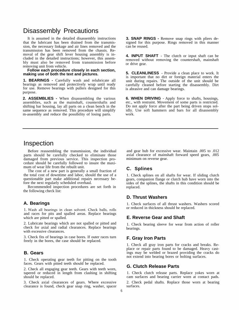
Disassembly PrecautionsIt is assumed in the detailed disassembly instructions
that the lubricant has been drained from the transmis-sion, the necessary linkage and air lines removed and thetransmission has been removed from the chassis. Re-moval of the gear shift lever housing assembly is in-cluded in the detailed instructions; however, this assem-bly must also be removed from transmission beforeremoving unit from vehicle.
Follow each procedure closely in each section,making use of both the text and pictures.
1. BEARINGS - Carefully wash and relubricate allbearings as removed and protectively wrap until readyfor use. Remove bearings with pullers designed for thispurpose.
2. ASSEMBLIES - When disassembling the variousassemblies, such as the mainshaft, countershafts andshifting bar housing, lay all parts on a clean bench in thesame sequence as removed. This procedure will simplifym-assembly and reduce the possibility of losing parts.
3. SNAP RINGS - Remove snap rings with pliers de-signed for this purpose. Rings removed in this mannercan be reused.
4. INPUT SHAFT - The clutch or input shaft can beremoved without removing the countershaft, mainshaftor drive gear.
5. CLEANLINESS - Provide a clean place to work. Itis important that no dirt or foreign material enters theunit during repairs. The outside of the unit should becarefully cleaned before starting the disassembly. Dirtis abrasive and can damage bearings.
6. WHEN DRIVING - Apply force to shafts, housings,etc., with restraint. Movement of some parts is restricted.Do not apply force after the part being driven stops sol-idly. Use soft hammers and bars for all disassemblywork.
InspectionBefore reassembling the transmission, the individual
parts should be carefully checked to eliminate thosedamaged from previous service. This inspection pro-cedure should be carefully followed to insure the maxi-mum of wear life from the rebuilt unit.
The cost of a new part is generally a small fraction ofthe total cost of downtime and labor, should the use of aquestionable part make additional repairs necessary be-fore the next regularly scheduled overhaul.
Recommended inspection procedures are set forth inthe following check list:
A. Bearings1. Wash all bearings in clean solvent. Check balls, rollsand races for pits and spalled areas. Replace bearingswhich are pitted or spalled.
2. Lubricate bearings which are not spalled or pitted andcheck for axial and radial clearances. Replace bearingswith excessive clearances.
3. Check fits of bearings in case bores. If outer races turnfreely in the bores, the case should be replaced.
B. Gears1. Check operating gear teeth for pitting on the toothfaces. Gears with pitted teeth should be replaced.
2. Check all engaging gear teeth. Gears with teeth worn,tapered or reduced in length from clashing in shiftingshould be replaced.3. Check axial clearances of gears. Where excessiveclearance is found, check gear snap ring, washer, spacer
and gear hub for excessive wear. Maintain .005 to .012axial clearance of mainshaft forward speed gears, .005minimum on reverse gear.
C. Splines1. Check splines on all shafts for wear. If sliding clutchgears, companion flange or clutch hub have worn into thesides of the splines, the shafts in this condition should bereplaced.
D. Thrust Washers1. Check surfaces of all thrust washers. Washers scoredor reduced in thickness should be replaced.
E. Reverse Gear and Shaft1. Check bearing sleeve for wear from action of rollerbearings.
F. Gray Iron Parts1. Check all gray iron parts for cracks and breaks. Re-place or repair parts found to be damaged. Heavy cast-ings may be welded or brazed providing the cracks donot extend into bearing bores or bolting surfaces.
G. Clutch Release Parts1. Check clutch release parts. Replace yokes worn atcam surfaces and bearing carrier worn at contact pads.
2. Check pedal shafts. Replace those worn at bearingsurfaces.
6

H. Shifting Bar Housing Assembly1. Check yokes and blocks for wear at pads and leverslot. Replace worn parts.
2. Check yokes for alignment. Straighten those which arcsprung.
3. Check yokes for excessive wear; replace worn yokes.
4. Check lockscrews in yokes and blocks. Tighten and re-wire those found loose.
5. If housing has been dismantled, check neutral notchesof shifting bars for wear from interlock balls. Bars in-dented at points adjacent to the neutral notch should bereplaced.
1. Gear Shift Lever Housing Assembly1. Check spring tension on shift lever. Replace tensionspring and washer if lever moves too freely.
2. If housing is dismantled, check pivot or spade pin andcorresponding slot in lever for wear. Replace both partsif worn.
J. Bearing Covers1. Check covers for wear from thrust of adjacent bear-ing. Replace covers worn and grooved from thrust ofbearing outer race.
2. Check bores of covers for wear. Replace those wornoversize.
K. Oil Return Threads and Seals1. Check oil return threads in front bearing cover. If seal-ing action of threads has been destroyed by contact withinput shaft, replace the cover.
2. Check oil seal in mainshaft rear bearing cover. If scal-ing action of lip has been destroyed, replace seal.
L. Synchronizers1. Check high and low range synchronizers for burrs, un-even and excessive wear at contact surface, and metalparticles.
2. Check blocker pins for excessive wear or looscness.
3. Check synchronizer contact surfaces on the high andlow range gears for excessive wear.
M. Sliding Clutches1. Check all yokes and yoke slots in sliding clutches forextreme wear or discoloration from heat.
2. Check engaging teeth of sliding clutches for partialengagement pattern.
N. Front Bearing Cover1. Check inside hub of front bearing cover for wearcaused by backing off of drive gear bearing nut.
O. O-Rings1. Check all O-rings for cracks or distortion. Replace ifworn.
Reassembly PrecautionsMake sure that interiors of case and housings arc
clean. It is important that dirt be kept out of transmis-sion during reassembly. Dirt is abrasive and can dam-age polished surfaces of bearings and washers. Use cer-tain precautions, as listed below, during reassembly.
1. GASKETS - Use new gaskets throughout the trans-mission as it is being rebuilt. Make sure all gaskets areinstalled, as omission of gasket can result in oil leakageor misalignment of bearing covers, See "Location ofGaskets" heading.
2. CAPSCREWS - To prevent oil leakage, use threadsealant on all capscrews. See torque rating chart forrecommended torque.
3. O-RINGS - Lubricate all O-rings with siliconelubricant.
4. ASSEMBLY - Refer to the disassembly illustrationsas a guide to reassembly.
5. INITIAL LUBRICATION - Coat all thrust washersand splints of shafts with Lubriplate during installation
to provide initial lubrication, preventing scoring andgalling.
6. AXIAL CLEARANCES - Maintain original axialclearances of mainshaft forward speed gears of .005" to.012". Mainshaft reverse gear clearance is a minimum of.005".
7. BEARINGS - Use of flanged-end bearing drivers isrecommended for the installation of bearings. Thesedrivers apply equal force to both races of bearing, pre-venting damage to balls and races and maintaining cor-rect bearing alignment with shaft and bore. If tubular orsleeve type driver is used, apply force only to inner race.
8. UNIVERSAL JOINT COMPANION FLANGE - Pullthe companion flange tightly into place with the main-shaft nut, using 450-500 foot-pounds of torque. Makesure the speedometer gear has been installed on yoke. Ifa speedometer gear is not used, a replaement spacer ofthe same width must be used. Failure to pull the yoke orflange tightly into place will permits the shaft to moveaxially with resultant damage to rear bearing.
7

Shifting Controls
I. Deep Reduction Air Lines - RTO-1258LL
(Range Shift Air Lines Omitted for Clarity)
A. REMOVAL
1. Disconnect the signal air line (A) and the supplyair line (B) from between the transmission and thedeep reduction control valve mounted in the cab.
2. Disconnect the 1/4" ID deep reduction shift cylindersupply air line (C) from between the shift cylinder andthe tee fitting forward of the regulator.
3. Disconnect the 1/4" ID slave air valve supply line(D) from between the slave air valve and the tee fittingforward of the regulator.
B. INSTALLATION
1. Install the 18" 1/4" ID slave air valve supply line(D) between the slave air valve and the tee fitting for-ward of the regulator.
2. Install the 17" supply air line (C) between the fittingforward of the regulator and the deep reduction shiftcylinder.
3. Install the control valve supply air line (B) betweenthe slave air valve and the "IN" port of the controlvalve.
4. Install the signal air line (A) between the deep re-duction shift cylinder and the "OUT" port of the con-trol valve.
8

II. Splitter Gear Air Lines - RT-12513 Series (Two Position Valve)
(Range Shift Air Lines Omitted for Clarity)
A. REMOVAL
1. Disconnect the white 1/8" OD supply air line (A)from between the tee fitting on the slave air valve andthe "S" port on the selector valve.
2. Disconnect the black 1/8" OD signal air line (B)from between the splitter shift cylinder and the "D"port of the selector valve.
3. Disconnect the 1/4" ID supply air line (C) frombetween the tee fitting forward of the regulator and thesplitter shift cylinder.
4. Disconnect the 18" 1/4" ID slave air valve supplyline (D) from between the air valve and the tee fittingforward of the regulator.
B. INSTALLATION
1. Connect the 18" 1/4" ID supply air line (D) betweenthe slave air valve and the tee fitting forward of theregulator.
2. Connect the 1/4" ID supply air line (C) betweenthe splitter shift cylinder and the tee fitting forward ofthe regulator.
3. Connect the black 1/8" OD signal air line (B) be-tween the splitter shift cylinder and the "D" port ofthe selector valve.
4. Connect the white 1/8" ID supply air line (A) be-tween the tee fitting on the slave air valve and the "S"port on the selector valve.
9

Shifting Controls - continued
III. Splitter Gear Air Lines - RT-12513 Series (Three position valve)
(Range Shift Air Lines Omitted for Clarity)
A. REMOVAL1. Disconnect the white 1/8" OD supply air line (A)from between the slave air valve and the selector valve.
2. Disconnect the black 1/8" OD range shift signal airline (B) from between the slave air valve and theselector valve.
3. Disconnect the black 1/8" OD splitter shift signalair line (C) from between the selector valve and thesplitter shift cylinder.
4. Disconnect the "A" OD supply air line (D) frombetween the splitter shift cylinder and the tee fittingforward of the regulator.
5. Disconnect the 1/4" ID slave air valve supply line(E) from between the slave air valve and the tee fittingforward of the regulator.
10
B. INSTALLATION1. Install the 18" 1/4" ID supply air line (E) betweenthe slave air valve and the tee fitting forward of theregulator.
2. Install the 17" 1/4" ID supply air line (D) betweenthe splitter shift cylinder and the tee fitting forward ofthe regulator.
3. lnstall the 1/8" OD signal air line (C) between thesplitter shift cylinder and the "R" port of the selectorvalve.
4. Install the 1/8" OD signal air line (B) between theslave air valve and the "F" port of the selector valve.
5. Install the 1/8" OD supply air line (A) between theslave air valve and the "S" port of the selector valve. !

—
IV. Range Shift Air Lines - All Models
A. REMOVAL
1. Disconnect the black and white 1/8" OD air lines(A and B) from between the slave air valve and therange shift control valve.
2. Disconnect the two 1/4" ID air lines from betweenthe slave air valve side cap and the range shift cylinder.
B. INSTALLATION
1. Disconnect the black and white 1/8" OD supply airline between the forward port on the slave air valveand the rear port on the range shift control valve.
2. Install the black 1/8" OD signal air line between therear port on the slave air valve and the forward porton the range control valve.
3. Use the chart to install the "A" ID air lines betweenthe slave air valve side cap and the range shift cylinder.
11

Shifting Controls - continued
V. Two and Three Position Selector Valves
A. REMOVAL AND DISASSEMBLY
1. Disconnect all air lines to the valve. Loosen the jamnut securing the valve to the gear shift lever and turnthe valve from the lever.
2. Remove the three screws on the bottom of the valveand lift the top cover from the body.
3. Remove the actuator from the top cover post andremove the springs, seals, O-rings and detent partsfrom the actuator.
B. REASSEMBLYAND INSTALLATION1. Refer to the drawing for proper assembly of thesprings, seals, O-ring and detent parts. Use a VERYSMALL amount of silicone lubricant on the O-rings toavoid clogging the valve ports.
2. Install the air lines with their sheathing and O-ringson the gear shift lever.
3. Install the jam nut on the lever and install the selec-tor valve. Use the jam nut to lock the valve in positionwith the actuator button facing the driver's seat.
4. Install the 1/8" OD air lines.
12

VI. Range Control Valve
.
A. REMOVAL AND DISASSEMBLY
1. Disconnect the air lines and loosen the clamp secur-ing the valve to the gear shift lever. Remove valve.
2. Remove the four screws to separate the front andrear housings and remove the slide and two sets ofposition springs and balls.
3. Remove the valve plate, insert O-rings and wavewasher from the valve bodies.
4. If necessary, remove the two felt seals. Punch outthe roll pin to remove the button from the slide.
13
B. REASSEMBLYAND INSTALLATION1. Refer to the drawing for proper reassembly. Use aVERY SMALL amount of silicone lubricant on theO-rings to avoid clogging the ports. A small amount ofgrease on the position springs and balls will help tohold them in place during reassembly.
2. Install the air lines with their sheathing and O-ringson the gear shift lever.
3. Secure the valve on the gear shift lever with theclamp. The control button should face to the front andbe approximately 6“ below the centerline of the shiftknob or selector valve.
4. Attach the air lines.

Shifting Controls - continued
VII. Slave Air Valve - All Models
1 4

A. REMOVAL AND DISASSEMBLY
1. Turn out the four capscrews, jar lightly to break thegasket seal and remove the air valve from the adapterplate.
2. Remove the alignment sleeve which will be either inthe adapter plate bore or on the back of the air valve.
3. Chuck the valve in a vise by the top and bottom andremove all brass fittings if necessary. Turn out the twoscrews and remove the side cap.
4. Remove the valve insert from the piston and removethe O-ring from the valve insert.
5. Remove the insert spring from the piston.
6. Turn the end cap from the valve body and removethe piston from the bore.
7. Remove the two O-rings from the piston.
8. Remove the nylon plug from the piston and removethe O-ring from the plug.
9. Remove the actuating spring and plunger from theadapter plate or case bore.
10. If so equipped, turn out the two Allen head screwsand two capscrews and remove the adapter plate fromthe transmission side.
15

Shifting Controls - continued
VII. Slave Air Valve - All ModelsB. REASSEMBLY AND INSTALLATION
I 11. If so equipped, install the adapter plate and gasketon the transmission with the two Allen head screws andtwo capscrews. Use the alignment sleeve to make surethat the bore in the adapter plate lines up properly withthe case bore.
2. Install the actuating plunger in the plate bore withthe small end facing out.
3. Install the actuating spring over the plunger.
4. Install the O-rings on the piston and apply a thincoat of silicone lubricant. Install the piston in the valvebody with the large end facing out and the piston borelined up with the slot in the side cap mounting surface.
5. Install the O-ring on the plug and apply a thin coatof silicone lubricant. Insert the plug into the pistonbore with the flat surface facing out.
6. Install the insert spring in the bore. Install the O-ringon the valve insert and apply a thin coat of siliconelubricant. Install the valve insert in the bore with thelarge end facing out.
7. Apply a thin coat of Lubriplate to the machined face ofthe side cap and install the side cap on the valve body.
8. Install the end cap on the valve body. DO NOT usemore than 40 lbs.-ft. of torque or the end cap will bindthe piston.
9. Install the alignment sleeve in the bore in the back ofthe valve and install the valve and gasket on the adapterplate. If previously removed, install the brass fittings onthe valve.
16

VII. Filter/Regulator Assembly - All Models
* Not used with RT-12509 Series Transmissions
A. REMOVAL AND DISASSEMBLY
1. Turn out the two retaining capscrews and removethe assembly from the transmission.
2. Turn out the two clamp nuts and remove the filter/regulator assembly from the bracket.
3. Remove the fittings and if necessary, turn the regu-lator from the filter.
4. If necessary, turn the end cap from the filter to re-move the filter core. Use caution as the end cap isspring loaded.
B. REASSEMBLYAND INSTALLATION1. Refer to the drawing for reassembly of the air filter.
2. Secure the nipple and regulator to the "OUTLET"port of the filter. Note that the larger of the two boreson the regulator attaches to the filter.
3. Secure the filter to the bracket with the "U" clamp,nuts and lockwashers.
4. Install the two range shift air lines between the slaveair valve and the range shift cylinder and secure thefilter/regulator assembly to the auxiliary housing withthe two capscrews.
17

Shifting Controls - continued
IX. Gear Shift Lever Housing - All Models
OLD STYLE NEW STYLE
18

A. REMOVAL AND DISASSEMBLY
1. Turn out the capscrews, jar lightly to break the gas-ket seal and remove the gear shift lever housing fromthe shift bar housing.
2. Secure the housing in a vise and use a large screw-driver to twist between the spring and side of the hous-ing, forcing the spring from under the three lugs. Doone coil at a time. Remove the spring.
3. Remove the washer and gear shift lever.
4. Remove the spade pin or pivot pin, nut and washerfrom the bore in the housing. If necessary, remove theO-ring from the housing.
B. REASSEMBLYAND INSTALLATION
1. Install the spade pin or pivot pin, nut and washer inthe bore in the housing. If previously removed, installthe O-ring in the groove.
2. Install the gear shift lever in the housing, fitting theslot in the lever ball over the spade pin.
3. Place the tension spring washer over the lever ballwith the dished side up:
4. Seat the tension spring under the lugs in the housing,seating one coil at a time. Use of a spring driving toolis recommended.
5. Make sure that the three tension springs and ballsare in the shift bar housing bores and install the gearshift lever housing and gasket on the shift bar housing.
19
Shifting Controls - continued
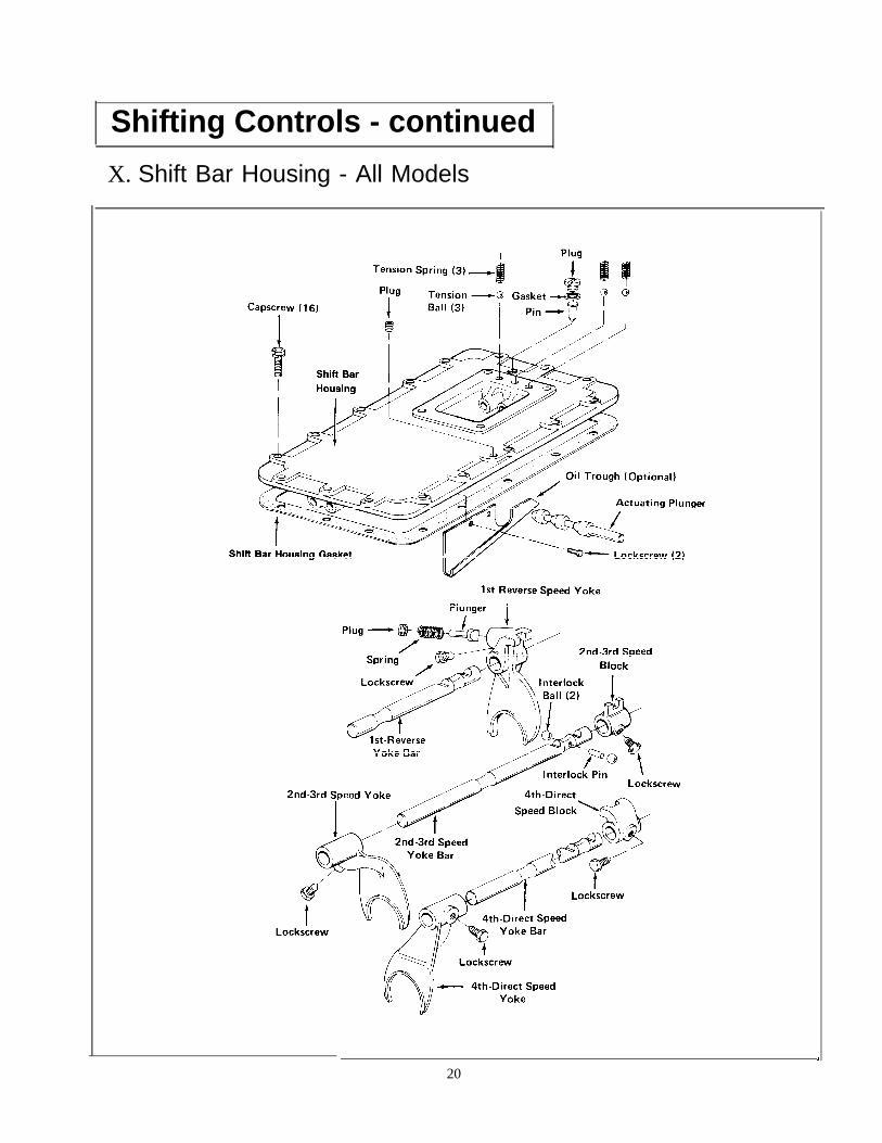
X. Shift Bar Housing - All Models
20

A. REMOVAL AND DISASSEMBLY
1. Make sure that the shift bars are in the neutral posi-tion. Remove the three tension springs, (arrow ). Turnout the retaining capscrews, jar lightly to break the gas-ket seal and lift the shift bar housing from the frontcase. Remove the three tension balls from the housingbores by tipping the housing slightly.
4. Remove the actuating plunger.
2. Mount the housing in a vise using caution to avoidmarring the machined mounting surface. If so equipped,remove the oil trough. Cut and remove all of- t h elockwires. Turn out the lockscrews and remove the di-rect speed shift bar, yoke and block.
5. Turn out the lockscrew and remove the reverse speedshift bar and yoke. If necessary, turn out the plug onthe yoke and remove the spring and plunger. Use cau-tion as the plug is spring loaded.
3. Turn out the lockscrews and remove the 2nd speedshift bar, yoke and block. As the notch clears the hous-ing boss, remove the interlock pin, (arrow).
6. Remove the two interlock balls from the bore in thehousing boss.
21

Shifting Controls - continued
X. Shift Bar HousingB. REASSEMBLY AND INSTALLATION
1. If previously removed, install the reverse-stopplunger in the reverse yoke. Make sure that the plungeris fully seated in the bore.
2. Install the spring in the bore and on the plunger.
3. Apply adhesive sealant to the plug threads and partiallyinstall the plug. Use the tip of the gear shift lever to pushthe plunger back into the bore to compress the spring.Tighten the plug fully and then back off 1/2 - 1-1/2 turns.Stake the plug threads in the hole.
4. Install the reverse shift bar and yoke. Install the yokelockscrew; tighten and wire securely.
5. Install the actuating plunger.
6. Install one of the two interlock balls in the housingbore, making sure that the ball goes all the way to thebottom of the bore and rests on the reverse shift bar.
22

7. Install the 2nd speed shift bar, yoke and block, in-serting the interlock- pin in the neutral notch of the bar,(arrow). Install the yoke and block lockscrews; tightenand wire securely. On "F" model transmissions, use theshort lockscrew in the shift block.
8. Install the remaining interlock ball,
9. Install the direct speed shift bar, yoke and block. In-stall lockscrews and wire securely. If so equipped, installthe oil trough with the two lockscrews and wire securely.
.
10. Install the three tension balls; one in each bore.
11. Install the shift bar housing and gasket on thefront case, fitting the yoke slots into the mainshaftsliding clutch gears. The shift bars and clutches mustbe in the neutral position. Install the three tensionsprings in the bores.
.
12. Secure the housing with the retaining capscrews.I
23

Auxiliary Sections
I. Removal and lnstallation -All ModelsA. REMOVAL FROM FRONT CASE
NOTE:The RT-12513 auxiliary section is shown inthe following steps. However, the procedure isthe same for RT-12509 series and RTO-1258LL transmissions.
1. If not previously removed, use two clutches in thefront case to lock the transmission in two gears and usea large breaker bar to turn the output shaft nut fromthe output shaft.
2. Remove the stop nut washer and companion flange oryoke from the splines of the output shaft.
3. Turn out the capscrews securing the auxiliary sec-tion to the front case.
4. insert three puller screws in the tapped holes in theauxiliary section flange and tighten evenly to move theauxiliary approximately 1/2" to the rear.
5. Attach a lifting bracket at the top center of the auxil-iary section. Move the auxiliary to the rear and off thefront case dowel pins. Mount the auxiliary in a viseusing caution to avoid damage to the machined surfaceof the flange.
2 4

B. INSTALLATION ON THE FRONT CASE
1. Install the gasket on the front case. Attach a liftingbracket and chain hoist to the top center of the auxiliarysection and guide the section on to the front case dowelpins. The two auxiliary countershafts will mesh withthe drive gear and the front of each shaft will seat inthe two bearings installed in the front section. Movethe assembly evenly, rotating the drive gear, if neces-sary, to properly mesh gears.
3. Install the speedometer drive gear or replacementspacer on the hub of the flange or yoke. Install theflange on the splines of the output shaft.
NOTE:The auxiliary section can also be installed bysetting the front section vertically on woodblocks and lowering the auxiliary section ontothe front case with a chain hoist attached to anoutput shaft lifting bracket. This procedure isrecommended for installation of the RTO-1258LL auxiliary section due to the extremelength and weight of the countershaft as-semblies.
2. With the auxiliary section fully into position against thefront case, install the capscrews.
4. Lock the front case by engaging two sliding clutchesand secure the flange or yoke with the elastic stop nut,using 450-500 lbs./ft. or torque. The nut should bepre-lubricated.
25

Auxiliary Sections - continued
II. RT-12509 Auxiliary Section DisassemblyA. REMOVAL AND DISASSEMBLY
OF THE RANGE SHIFT CYLINDER ASSEMBLY
1. Turn out the four capscrews and remove the shiftcylinder cover. Remove the nut from the end of theyoke bar.
2. Cut the lockwire and turn out the two yoke lock-screws.
3. Pull the yoke bar forward and out of the housing. Re-move the piston from the cylinder bore and if necessary,remove the O-rings from the ID and OD of the piston.
4. Remove the shift yoke, turn out the four capscrewsand remove the cylinder housing from the auxiliaryplate. If necessary, remove the O-ring from the bore inthe housing.
26

B. REMOVAL OF THEAUXILIARY COUNTERSHAFTS
C. REMOVAL AND DISASSEMBLYOF THE SYNCHRONIZERASSEMBLY
1. Turn out the capscrews and remove the two counter-shaft rear bearing covers. Remove the snap ring fromthe rear of each countershaft.
2. Pull the synchronizer assembly forward and from thesplines of the output shaft.
2. Use a soft bar and mall to drive the countershaftsforward and from the rear bearings. Use a soft bar totap the bearings to the rear and from the auxiliaryplate. Tap on the outer race to avoid damaging thebearings.
2. Pull the direct ring from the blocker pins of the lowspeed ring; cover the assembly with a cloth during this step toavoid losing the three springs which will be released fromthe direct ring. Remove the sliding clutch gear fromthe low speed ring.
27

Auxiliary Sections - continued
II. RT-12509 Auxiliary Section DisassemblyD. REMOVAL AND DISASSEMBLY
OF THE LOW SPEED GEAR AND OUTPUT SHAFT
1. Use a soft bar and mall to drive the output shaft for-ward and from the rear bearing. 2. Remove the bearing inner spacer from the shaft.
28

5. Remove the two bearing cups and outer spacer fromthe auxiliary plate bore.
3. Using the front face of the low speed gear as a base,press the shaft through the gear and bearing. If neces-sary, remove the snap ring from the ID of the gear.
4. Turn out the cpascrews and remove the rear bearinghousing. If necessary, remove the oil seal from the hous-ing. Remove the rear bearing cone from the housing.
29

Auxiliary Sections - continued
III. RT-12509 Auxiliary Section ReassemblyA. REASSEMBLY OF THE LOW SPEED GEAR AND OUTPUT SHAFT
1. Place the output shaft on a bench with the threadedend up and install the splined spacer on the shaft, largediameter down.
3. Install the low speed gear on the shaft with the clutch-ing teeth down and engaging the splines of the spacer.
2. Mark any two adjacent teeth on the low speed gearand then mark the two teeth directly opposite.
4. Install the washer on the shaft, flat surface down.
30

5. Heat and install the front bearing cone on the shaftand against the washer, taper up. The two bearingcones and cups are a matched set. Make sure that thecorrect cone for cup is used as indicated by markings.
NOTE: IHeating of the bearing cones is recommend-cd, provided the bearing is not heated over275oF. Heat lamps are recommended as aheating source.
6. Install the bearing inner spacer on the shaft andagainst the bearing cone.
7. Place the front cup into the housing bore with thethick end up.
8. Stack the outer spacer and i-car cup, shoulder up,on the front cup and tap all three evenly into the boreuntil the shoulder of the rear cup seats against theauxiliary plate.
31
Auxiliary Sections - continued
III. RT-12509 Auxiliary Section ReassemblyA. REASSEMBLY OF THE LOW SPEED GEAR AND OUTPUT SHAFT.
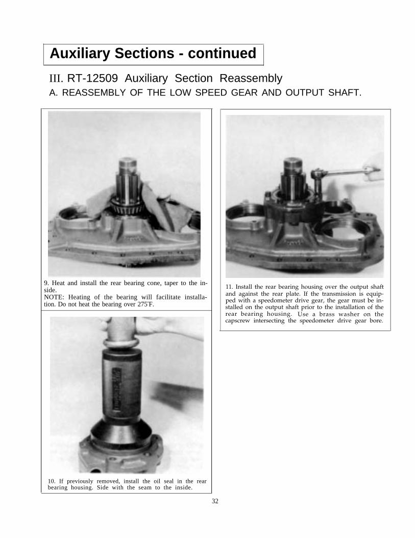
9. Heat and install the rear bearing cone, taper to the in-side.NOTE: Heating of the bearing will facilitate installa-tion. Do not heat the bearing over 275oF.
11. Install the rear bearing housing over the output shaftand against the rear plate. If the transmission is equip-ped with a speedometer drive gear, the gear must be in-stalled on the output shaft prior to the installation of therear bearing housing. Use a brass washer on thecapscrew intersecting the speedometer drive gear bore.
10. If previously removed, install the oil seal in the rearbearing housing. Side with the seam to the inside.
32

B. REASSEMBLY OF THE SYNCHRONIZER ASSEMBLY
1. Place the larger (low speed) brass synchronizer ringon a bench with the pins facing up and install thesliding clutch gear over the ring, protruding clutchingteeth down.
I4. Apply pressure to the direct ring while twistingcounterclockwise to fully seat the direct ring on thelow speed ring pins.
2. Install the three springs in the direct ring,
I
5. Mount the auxiliary plate in a vise in the uprightposition and install the synchronizer assembly on theoutput.
3. Install the direct ring on the low speed ring pins,seating the springs against the pins.
33

Auxiliary Sections - continued1
III. RT-12509 Auxiliary Section ReassemblyC. TIMING AND INSTALLATION OF THE AUXILIARY
COUNTERSHAFT ASSEMBLIES
1. On the small diameter low range gear of each counter-shaft, mark the tooth which is stamped with an "O".
3. Install the snap ring on the rear of each countershaft.
2. Place one of the countershafts into position in the rearplate, meshing the marked tooth on the countershaft be-tween two of the marked teeth on the low speed gear. Usea soft bar to start the rear bearing onto the shaft and intothe case bore and use a bearing driver to complete theinstallation. Check the synchronizer assembly duringbearing installation to make sure that the springs do notpop out. Repeat the procedure for the remaining coun-tershaft.NOTE: Make sure that the bearing inner race is in-stalled on teh front of each auxiliary countershaft.
4. Install the countershaft rear bearing covers.
34

D. INSTALLATION OF THE RANGE SHIFT CYLINDER ASSEMBLY
1. Install the cylinder housing and gasket in the rearplate with the air fitting facing up. If previously re-moved, install the O-ring in the bore in the cylinder andcoat the O-ring with a thin application of silicone lubri-c a n t .
3. Install the O-rings in the OD and ID of the piston,apply a thin coat of silicone lubricant to the O-ringsand install the piston on the yoke bar and in the cyl-inder housing bore with the flat side facing out.
2. Install the shift yoke on the sliding clutch gear of thesynchronizer and insert the yoke bar through the yokeand cylinder housing. Secure the yoke to the bar withthe two yoke lockscrews; tighten and wire securely. 4. Secure the piston to the yoke bar with the nut. In-
stall the gasket and voer with the air fitting to the top.
35

Auxiliary Sections - continued
IV. RTO-1258LL Auxiliary Section DisassemblyA. REMOVAL AND DISASSEMBLY
OF THE RANGE SHIFT CYLINDER ASSEMBLY
,1. Turn out the four capscrews and remove the rangeshift cylinder cover. Remove the nut from the end ofthe yoke bar.
2. Cut the lockwire and turn out the two yoke lock-screws.
3. Remove the piston from the yoke bar and if necessary,remove the O-rings from the ID and OD of the piston. Pushthe yoke bar forward and from the housing.
4. Remove the shift yoke, turn out the four capscrewsand remove the cylinder housing from the auxiliaryhousing. If necessary, remove the O-ring from the borein the cylinder housing.
63

B. REMOVAL OF THEAUXILIARY COUNTERSHAFTS
C. REMOVAL ANDDISASSEMBLY OF THESYNCHRONIZER ASSEMBLY
1. Turn out the capscrews and remove the two counter-shaft rear bearing covers. Remove the snap ring fromthe rear of each countershaft.
l. Pull the synchronizer assembly from the splincs ofthe range mainshaft.
2. Use a soft bar and mall to drive each countershaftforward and from the rear bearing. Use a soft bar to tapthe bearings to the rear and from the housing bores.Tap on the outer races to avoid damaging the bearings.
NOTE:When driving the countershafts, check thesynchronizer assembly periodically to makesure that the direct ring is not moving for-ward. If the direct ring is allowed to slide offthe low speed ring blocker pins, the threesprings in the assembly could jump out of thebores and get lost.
2. Pull the direct ring from the blocker pins of the lowspeed ring. Cover with a cloth as the three pins will bereleased at the blocker pin locations. Remove the slid-ing clutch gear from the pins of the low speed ring.
37
Auxiliary Sections - continued
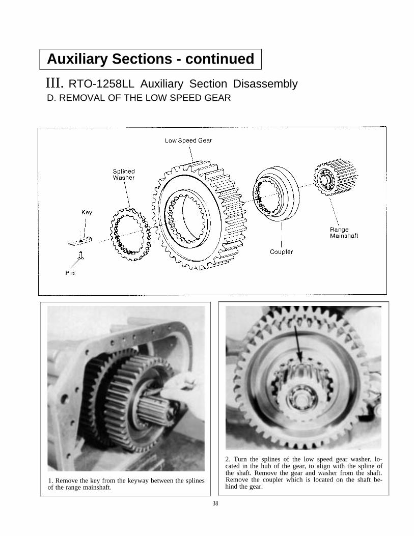
III. RTO-1258LL Auxiliary Section DisassemblyD. REMOVAL OF THE LOW SPEED GEAR
1. Remove the key from the keyway between the splinesof the range mainshaft.
38
2. Turn the splines of the low speed gear washer, lo-cated in the hub of the gear, to align with the spline ofthe shaft. Remove the gear and washer from the shaft.Remove the coupler which is located on the shaft be-hind the gear.

E. REMOVAL OF THE DEEP REDUCTION SHIFT CYLINDER
1. Remove the shift cylinder cover.
2. Cut the lockwire and turn out the lockscrew fromthe shift yoke.
3. Push the yoke bar to the rear and remove from thehousing. If necessary, remove the O-ring from the bar,(arrow).
4. Remove the shift yoke and cylinder housing fromthe auxiliary housing. If necessary, remove the O-ringfrom the bore in the cylinder housing.
39

Auxiliary Sections - continued
IV. RTO-1258LL Auxiliary Section DisassemblyF. REMOVAL OF THE RANGE MAINSHAFT
1. Remove the snap ring from the front of the quill.NOTE: Snap ring used on current production models mustbe removed by spreading with a screwdriver.
2. Move the sliding clutch forward and against the snapring of the range mainshaft. Insert jaws of puller behindsliding clutch gear and pull the mainshaft from the quill.
3. Remove the bearing from the shaft. If necessary, usean inside jaw impact puller.
4. Remove the snap ring from the OD of the mainshaftand, if necessary, press the bushing from the mainshaftbore, (arrow).
40

G. REMOVAL OF THE DEEP REDUCTION GEARAND OUTPUT SHAFT ASSEMBLY
1. Turn out the capscrews and remove the rear bearinghousing. If necessary, remove the oil seal from the hous-ing.
4. Use a soft bar and mall to drive the output shaft for-ward and from the auxiliary housing.
2. Remove the snap ring from the output shaft. 5. Use the deep reduction gear as a base to press the rearbearing from the output shaft. This will free the gear,washer, spacer and oil deflector.
3. Remove the speedometer drive gear or replacementspacer from the shaft.
6. Remove the two bear ing cups and outer spacerthe auxil iary housing bore.
41

Auxiliary Sections - continued
V. RTO-1258LL Auxiliary Section ReassemblyA. REASSEMBLY OF THE DEEP REDUCTION GEAR AND OUTPUT SHAFT
I
I
I
1. Place the output shaft on blocking with the threadedend up. Use caution to avoid damage to the quill.
2. Install the splined spacer on the shalt.
I42

3. Mark any two adjacent teeth on the reduction gearand then mark the two teeth directly opposite.
5. Install the washer on the shaft and against the gearwith the side with the large groove facing up.
6. Install the oil deflector in the rear housing bore withthe cupped surface facing up. Use a large bearing driverto drive the deflector down until the top surface of thedeflector is 2" below the machined surface of the outputshaft bore.
4. Install the reduction gear on the shaft and spacer withthe clutching teeth down.
NOTE: I f ava i lab le , use two bear ing outer spacersstacked on top of each other to drive the oil deflector intothe bore. The deflector will be at the proper depth whenthe top of the top spacer is flush with the machined sur-face of the output shaft bore.
43

Auxiliary Sections - continued
V. RTO-1258LL Auxiliary Section ReassemblyA. REASSEMBLY OF THE DEEP REDUCTION GEAR AND OUTPUT SHAFT (Cont.)
7. Install the rear housing over the output shaft, allowingthe housing to rest on the reduction gear.
8. Heat the front bearing cone and install in the bore andagainst the oil deflector with the cone surface facing up.
NOTE: Heating off the bearings will facilitate installa-tion. Do not heat the bearings over 275oF.
9. Install the bearing inner spacer on the shaft andagainst the front bearing cone.
10. Stack the two bearing cups and outer spacer in theoutput shaft bore in the proper sequence. Make sure thatthe front bearing cup taper matches the taper directionofÍ the front bearing cone.
44

11. Tap the two cups and outer spacer lightly and evenlyinto the case bore until the lip of the rear cup seatsagainst the machined surface. It will be necessary toblock under the rear housing slightly to permit the out-put shaft assembly to more far enough.
12. Heat and install the rear bearing cone on the shaftand in the rear cup, taper facing down.
13. Install the speedometer drive gear or replacementspacer on the shaft and against the rear bearing cone andsecure with the snap ring.
14. If previously removed, install the oil seal in the rearbearing housing with the seam to the inside. Use of aproper oil seal driver is recommended.
.
.
15. Install the rear bearing housing and gasket on theauxiliary housing, using a brass washer (arrow), at thespeedometer bore. Make sure to match one ofÕ thenotches in the surface of Õthe bearing housing with the oilport in the auxiliary housing.
16. Install the sliding clutch gear on the front of theshaft, internal clutching teeth to the rear.
45

Auxiliary Sections - continued
V. RTO-1258LL Auxiliary Section ReassemblyB. INSTALLATION OF THE RANGE MAINSHAFT ASSEMBLY
3. Install the bearing in the mainshaft and on the quill.A 3/4" socket can be used to install the bearing keepingthe socket centered on the inner race and tapping light-ly with a soft bar.
1. If previously removed, install the snap ring in thegroove on mainshaft. Install the bushing in the shaft bydriving or pressing until the top of the bushing is flushwith the bottom of the chamfer cut in the mainshaftbone, (arrow).
2. Install the mainshaft on the quill of the output shaft,seating the bushing on teh rear surface of the quill.
4. Install the snap ring on the front of the quill. Use ofthe proper snap ring driver is recommendcd. (See toolreference section ).
46

C. REASSEMBLY AND INSTALLATIONOF THE DEEP REDUCTION SHIFT CYLINDER
1. Install the O-ring in the bore of the shift cylinder andinstall the cylinder in the auxiliary housing with the airchannel to the right.
2. Install the yoke in the sliding clutch yoke slot with thelockscrew hole facing up.
3. Install the O-ring in the yoke bar groove and push theyoke bar forward and through the cylinder housing andthe shift yoke. Install the yoke lockscrew; tighten andwire securely.
4. Install the cylinder cover, aligning the air channelwith the channel in the cylinder housing.
47

Auxiliary Sections - continued
V. RTO-1258LL Auxiliary Section ReassemblyD. INSTALLATION OF THE LOW SPEED GEAR
1. Install the coupler on the shaft, large diameter to therear.
2. Install the low speed gear on the shaft and againstthe coupler, dished side to the front.
48
3. Install the splined washer on the shaft and in thehub of the gear. Turn the washer to lock the gear onthe shaft. Washers with varying thicknesses are available.Use the washer which provides the tightest fit.
4. Install the key in the keyway, inserting the thick endbetween the splines of the washer.

E. REASSEMBLY AND INSTALLATION OF THE SYNCHRONIZER ASSEMBLY
1. Place the low speed ring on a workbench with thepins facing up. Install the sliding clutch on the lowspeed ring with the dished side up.
2. Coat the three synchronizer springs with grease tohold them in place and install in the three bores in thedirect ring. Place the ring over the pins of the low speedring with the springs against the blocker pins.
3. Apply pressure to the dircct ring and twist to com-press the springs and seat the ring fully on the pins. Itmaybe helpful to place the assembly on a rag duringthis step to prevent the ring on the bottom from turning.
4. Install the synchronizer on the range mainshaft withthe low speed ring seated fully into the low spced gearbore.
49

Auxiliary Sections - continuedV. RTO-1258LL Auxiliary Section ReassemblyF. TIMING AND INSTALLATION OF THE AUXILIARY COUNTERSHAFTS
1. Mark the tooth which is stamped with an "o" on eachof the three sets of gears on the auxiliary countershafts.
3. Install the snap ring in the groove on the rear of eachcountershaf t .
sets of marked teeth on each of the gears. Hold the coun-
2. Place one of the countershafts into position in the case,meshing the marked teeth on the shaft between one of the
tershaft in position and use a soft bar to tap the rear bear-ing onto the shaft and into the case bore. Use a bearingdriver to complete installation of the bearing. Check thesynchronizer during bearing installation to make surethat the springs do no pop out. Repeat the procedure toinstall the remaining countershaft.
4. Install the two rear bearing covers.
IMPORTANT: Make sure that the bearing inner race isinstalled on the front of each countershaft.
50
G. REASSEMBLY AND INSTALLATION OF THE RANGE SHIFT CYLINDER
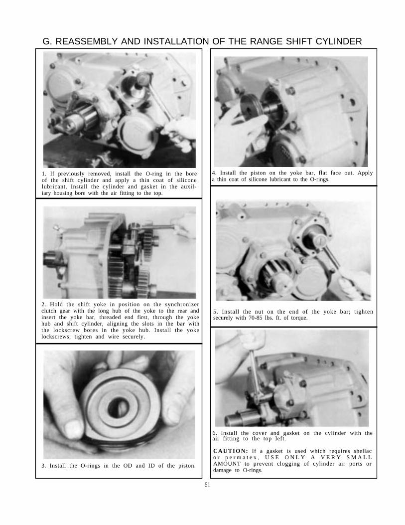
1. If previously removed, install the O-ring in the boreof the shift cylinder and apply a thin coat of siliconelubricant. Install the cylinder and gasket in the auxil-iary housing bore with the air fitting to the top.
4. Install the piston on the yoke bar, flat face out. Applya thin coat of silicone lubricant to the O-rings.
2. Hold the shift yoke in position on the synchronizerclutch gear with the long hub of the yoke to the rear andinsert the yoke bar, threaded end first, through the yokehub and shift cylinder, aligning the slots in the bar withthe lockscrew bores in the yoke hub. Install the yokelockscrews; tighten and wire securely.
5. Install the nut on the end of the yoke bar; tightensecurely with 70-85 lbs. ft. of torque.
6. Install the cover and gasket on the cylinder with theair fitting to the top left.
CAUTION: If a gasket is used which requires shellaco r p e r m a t e x , U S E O N L Y A V E R Y S M A L LAMOUNT to prevent clogging of cylinder air ports ordamage to O-rings.
3. Install the O-rings in the OD and ID of the piston.
51

Auxiliary Sections - continued
VI. RT-12513 Auxiliary Section DisassemblyA. REMOVAL AND DISASSEMBLY OF THE RANGE SHIFT CYLINDER
1. Remove the range shift cylinder cover and removethe nut from the end of the yoke bar.
.
2. Cut the lockwire and turn out the two yoke lock-screws.
52
3. Remove the piston from the yoke bar and if necessary,remove the O-rings from the OD and ID of the piston. Pushthe yoke bar forward and from the housing.
4. Remove the cylinder housing from the auxiliaryhousing. If necessary, remove the O-ring from thehousing bore, (arrow). Remove the shift yoke from thesynchronizer.
I

B. REMOVAL OF THE AUXILIARY COUNTERSHAFT BEARINGS
1. Remove the two countershaft rear bearing coversand remove the snap ring from the rear of each counter-shaft.
2. Use a soft bar and mall to drive the countershaftsforward approximately 1/2" to partially unseat thebearings.
3. Move the countershaft back to the rear to exposethe bearing snap rings.
,
4. Use a puller to remove the countershaft rearb e a r i n g s .
C. REMOVAL AND DISASSEMBLY OF THE SYNCHRONIZER ASSEMBLY
1. Spread the countershaft and remove the syn-chronizer.
2. Pull the direct ring from the pins of the low speedring. Cover the assembly with a cloth during this stepto prevent loss of the three springs. Remove the slidingclutch gear from the low speed ring.
53

Auxiliary Sections - continued
VI. RT-12513 Auxiliary Section DisassemblyD. REMOVAL OF THE LOW RANGE GEAR
1. Remove the key from the keyway between the splinesof the range mainshaft.
2. Turn the splines of the low speed gear washer toalign with the splints of the shaft.
54
3. Remove the low range gear and washer from theshaft.
4. Remove the coupler from the shaft and remove theright countershaft from the housing. The left counter-shaft cannot be removed at this time.
I
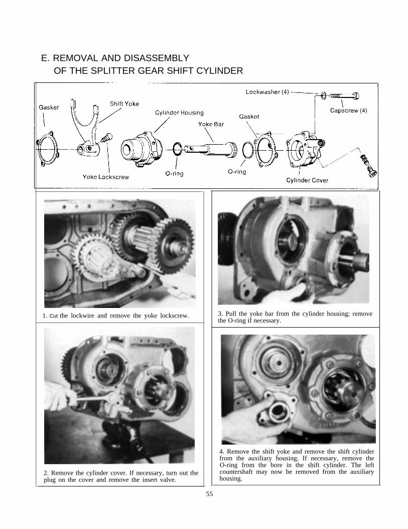
E. REMOVAL AND DISASSEMBLYOF THE SPLITTER GEAR SHIFT CYLINDER
1. Cut the lockwire and remove the yoke lockscrew.
2. Remove the cylinder cover. If necessary, turn out theplug on the cover and remove the insert valve.
3. Pull the yoke bar from the cylinder housing; removethe O-ring if necessary.
4. Remove the shift yoke and remove the shift cylinderfrom the auxiliary housing. If necessary, remove theO-ring from the bore in the shift cylinder. The leftcountershaft may now be removed from the auxiliaryhousing.
55

Auxiliary Sections - continued
VI. RT-12513 Auxiliary Section DisassemblyF. REMOVAL AND DISASSEMBLY OF THE RANGE MAINSHAFT ASSEMBLY
1. Remove the snap ring from the front of the rangemainshaft.
2. Use a puller on the sliding clutch to remove themainshaft and clutch from the output shaft quill.
3. If necessary, remove the bearing from the mainshaftby tapping lightly from the inside with the range shiftyoke bar or a similar size rod.
4. If necessary, remove the snap ring and bushing fromthe mainshaft. A 15/16" socket can be used by install-ing the back face of the socket from the inside of theshaft against the bushing and using a steel rod to driveagainst the socket.
5 6

G. REMOVAL AND DISASSEMBLY OF THE OUTPUT SHAFT
1. Use a soft bar and mall to drive the output shaft for-ward and from the rear housing. Do not allow the out-put shaft to fall on the quill, (arrow).
2. Use the splitter gear as a base to press the outputshaft through the gear, washer and bearing. If neces-sary, remove the snap ring from the bore of the splitterg e a r .
57
3. Turn out the capscrews and remove the rear bearingcover. If necessary, remove the oil seal from the coverwith a hammer and punch. Removal procedures willdamage the seal and removal should not be attemptedunless replacement of the seal is planned.
4. Remove the rear bearing cone and using a smallhammcr and punch, tap lightly to move the two bear-ing cups and outer spacer to the rear and from thehousing bore. Use caution to avoid marking the ma-chined surface of the bore.

Auxiliary Sections - continued
VII. RT-12513 Auxiliary Section ReassemblyA. REASSEMBLY AND INSTALLATION OF THE OUTPUT SHAFT ASSEMBLY
I
1. Place the output shaft on blocking to prevent damageto the quill and install the stepped spacer on the shaft,small diameter up.
2. Install the splined washer on the shaft, shoulder up. I
3. If previously removed, install the snap ring in thegroove in the splitter gear. Install the splitter gear onthe shaft and over the splined washer, snap ring up.
4. Install the rear washer on the shaft, flat side up.
5. Heat the front bearing cone and install on the shaftwith the taper up. (Do not heat the bearing over275oF).
NOTE:The two bearing cones and cups are amatched set. Make sure that the proper coneis used with the proper cup.
6. Install the bearing inner spacer on the shaft.
58

7. For timing purposes, mark any two adjacent teethon the gear and then mark the two teeth directly
10. Heat the rear bearing cone and install on the shaftand in the cup. make sure that the lip of the cup is fullyseated against the housing.opposite.
8. Start the front cup of the bearing into the auxiliarybore with the wide edge up. Stack the outer spacer andrear cup on the front cup and usc a driver to seat allthree evenly in the bore. Tap lightly to avoid drivingthe front cup out the bottom of the bore.
11. If previously removed, instll the oil seal in thebearing housing with the surface with the seam to thei n s i d e .
9. Place the housing over the output shaft, seating thebearing in the cup.
12. Install the bearing housing and gasket on the aux-iliary housing; use a brass washer on the capscrewwhich passes through the speedometer bore.
59

Auxiliary Sections - continued
VII. RT-12513 Auxiliary Section ReassemblyB. REASSEMBLY AND INSTALLING THE RANGE MAINSHAFT ASSEMBLY
4. Place the mainshaft on the output shaft quill.1. Install the splitter gear sliding clutch on the outputshaft, internal splines to the rear.
2. If previously removed, press the bushing in the main-shaft bore so that it is 1/16" below the face of thesha f t .
5. Install the front bearing in the mainshaft and on theq u i l l . A 3/4" socket can be used as a bearing driver.
3. If previously removed, install the snap ring in thegroove on the mainshaft.
6. Use a snap ring driver to install the snap ring on thequill.
60

C. INSTALLATION OF THE SPLITTER GEAR SHIFT CYLINDER
1. Mark the tooth which is stamped with an "O" on thesplitter gear of each auxiliary countershaft. This gearis located on the end of the shaft which has the snapring groove.
2. If the auxiliary countershaft front bearings are to bereplaced, use a puller to remove the inner race fromeach shaft. Heat and install the inner races from thenew bearings with the shoulder towards the gear.
3. Place the left countershaft into position, meshingthe marked tooth on the shaft between two of themarked teeth on the splitter gear.
4. Install the yoke in the sliding clutch gear slot withthe hub to the front.
5. If previously removed, install the O-rings on the pis-ton and in the bore of the cylinder and apply a thin coatof silicone lubricant. Install the cylinder housing andgasket in the auxiliary housing with the air channel tothe right, (arrow).
6. Push the yoke bar through the housing and yokehub, aligning the lockscrew bore with the identationi n t h e y o k e b a r .
61

Auxiliary Sections - continued
VII. RT-12513 Auxiliary Section ReassemblyC. INSTALLATION OF THE SPLITTER GEAR SHIFT CYLINDER
9. Install the exhaust screw in the cover to retain theinsert valve.7. Install the yoke lockscrew; tighten and wire securely.
10. Install the splitter cylinder cover and gasket on thecylinder housing with the exhause screw down. If gas-ket sealant is used, use only a small amount to avoidclogging the cylinder air ports.8. Install the insert valve in the cover as shown.
62

D. INSTALLATION OF THE LOW RANGE GEAR ASSEMBLY
1. Place the right countershaft into position with themarked tooth between two of the marked teeth on thesplitter gear. Make sure that the left countershaft isstill in time.
4. Install the washer on teh shaft and in the hub of thegear. Turn the washer to lock the gear on the shaft.
NOTE:Washers with varying thicknesses are available.Use the washer that provides the tightest fit.
2. Install the coupler on the shaft and against the snapring with the clutching teeth to the rear.
3. Install the low range gear on the shaft and againstthe coupler.
5. Insert the key in the keyway on the mainshaft withthe pin in the hole and the thick end between the splinesof the washer.
63

1
Auxiliary Sections - continued
VII. RT-12513 Auxiliary Section ReassemblyE. REASSEMBLY AND INSTALLATION OF THE SYNCHRONIZER ASSEMBLY
1. Place the sliding clutch on the pins of the low speedsynchronizer with the dished side of the clutch facingup.
2 . Use grease to hold the three springs in the direct ringbores and place the direct ring on the pins of the lowspeed ring. Scat the direct ring fully on the low speedpins by pushing down and twisting to compress thesprings. Install the synchronizer assembly on the rangemainshaft, seating the low speed ring fully in the gear.
F. INSTALLATION OF THE AUXILIARY COUNTERSHAFT REAR BEARINGS
1. Check to make sure that the countershaft are stillin time. Use a soft bar to start the bearings into thecase bores and complete installation with a bearingdriver and mall.
NOTE:Check the synchronizer assembly often whileinstalling the bearings to make sure that thedirect ring does not move forward and offthe low speed pins.
2. Install the snap ring in the groove at the rear of eachcountershaft. Install the two rear bearing covers andgaskets.
64
I

G. INSTALLATION OF THE RANGE SHIFT CYLINDER ASSEMBLY
1. If previously removed, install the O-ring in the shiftcylinder bore and apply a thin coat of siliconc lubri-cant, (arrow). Install the shift cylinder and gasket inthe auxiliary housing bore; secure with four capscrcws 4. Install the two yoke lockscrews; tighten and wire
securely.with the air fitting to thc top.
2. Place the shift yoke in the yoke slot on the synchro-nizer sliding clutch, long hub- of the yoke to the rear.
5. If previously removed, install the O-rings in the ODand ID of the piston and apply a thin coat of siliconelubricant. Install the piston on teh yoke bar and in thecylinder bore; secure with the nut.
6. Install the range shift cylinder cover and gasket onthe cylinder housing with the four capscrews. The airfitting should be to the top left.I
3. Install the yoke bar, inserting the threaded endthrough the yoke hub and cylinder bore.
6 5
Front Section - All Models
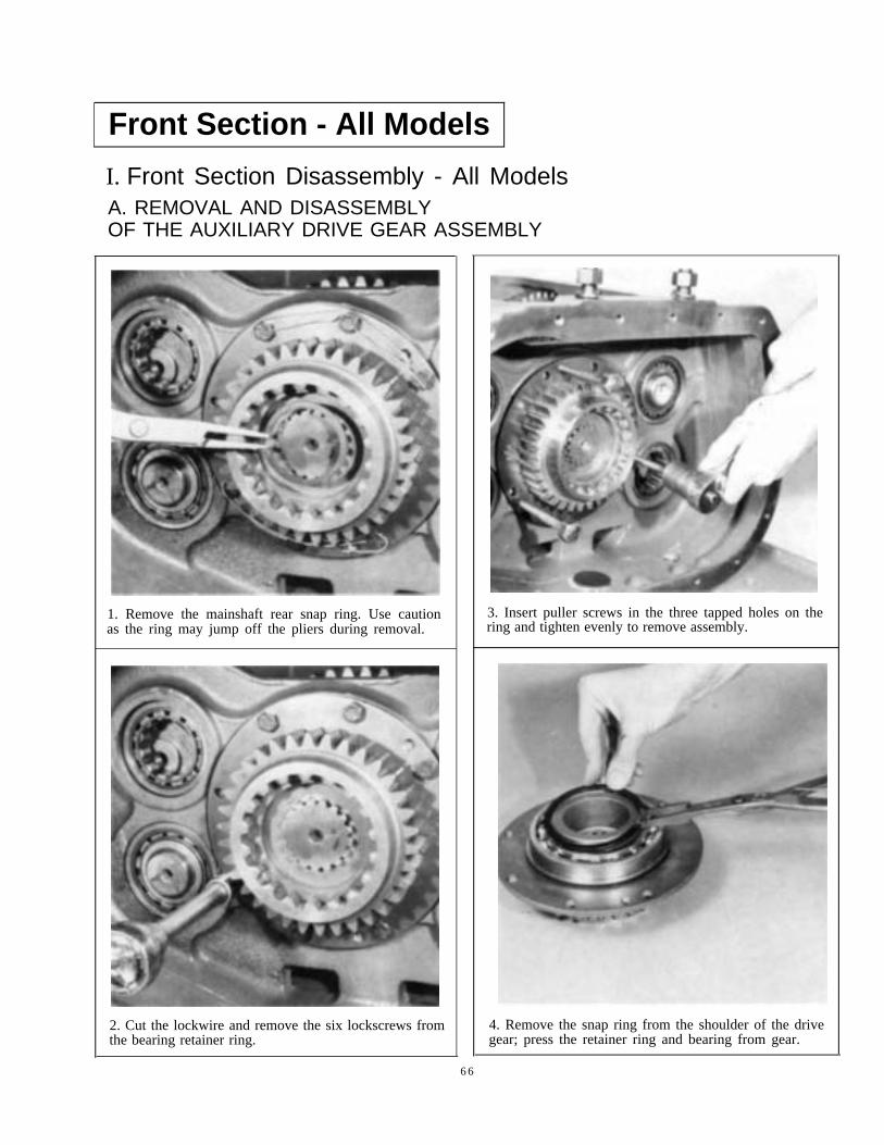
I. Front Section Disassembly - All ModelsA. REMOVAL AND DISASSEMBLYOF THE AUXILIARY DRIVE GEAR ASSEMBLY
1. Remove the mainshaft rear snap ring. Use cautionas the ring may jump off the pliers during removal.
2. Cut the lockwire and remove the six lockscrews fromthe bearing retainer ring.
3. Insert puller screws in the three tapped holes on thering and tighten evenly to remove assembly.
4. Remove the snap ring from the shoulder of the drivegear; press the retainer ring and bearing from gear.
6 6

B. REMOVAL AND DISASSEMBLYOF THE LEFT REVERSEIDLER GEAR ASSEMBLY
4. Remove the stop nut and washer.
1. Remove the snap ring from the ID of the mainshaftreverse gear.
2. Move the gear as far forward as possible into en-gagement with the sliding clutch.
3. Remove the bearing from the idler bore. If the bear-ing is to be re-used, use an inside jaw impact puller. Ifthe bearing is to be replaced, a crowÕs foot or pry barmay be used.
5. Remove the plug and attach an impact puller to theidler shaft. Remove shaft from case.
6. Remove the gear and thrust washer from the case.If necessary, press the bearing outer race from the gear.
7. Remove the bearing inner race and cup from theshaft; these parts may in some cases remain in the idlerbore.
6 7

Front Section - All Models - continued
I. Front Section Disassembly - All ModelsC. REMOVAL OF THE COUNTERSHAFT BEARINGS
NOTE:It is necessary to remove the bearings fromonly the right countershaft to remove themainshaft.
1. Remove the snap ring from the rear of each counter-shaft.
2. Use a soft bar and punch from inside the case todrive the rear bearings to the rear and from the casebores.NOTE:
Removal procedures will damage the bear-ings and removal should not be attemptedunless replacement of the bearings is planned.
58
3. Cut the lockwires, turn out the lockscrews and re-move the two front bearing retainer plates.
4. Move each countershaft to the rear approximately1/2" using a soft bar and mall.
5. Drive against the rear of each countershaft to movethem as far forward as possible. This will expose thefront bearing snap rings. Use a puller to remove the frontbearings. Remove the spacer from the front of-each coun-tershaft.

D. REMOVAL AND DISASSEMBLY OF THE MAINSHAFT ASSEMBLY
3. Pull the key from the mainshaft; this will unlock the parts
1. Block the right countershaft against the wall of thecase. Hold the reverse gear tight against the first speedgear and move the assembly to the rear and out of theinput shaft pocket. Tilt the front of the mainshaft upand lift from case. use caution as the reverse gear isfree and can fall off the shaft.
4. Remove the reverse gear spacer and washer.
5. Tip the front of the shaft up and twist back and forth.The gearing will slide off the rear of the shaft in theproper order for reassembly. If necessary, remove thesnap rings from the gears.
2. Remove the sliding clutch at the front of the shaftand remove the snap ring from the rear of the shaft.
69

Front Section - All Models - continued
I. Front Section Disassembly - All ModelsE. REMOVAL AND DISASSEMBLY OF THE DRIVE GEAR ASSEMBLY
1. Remove the front bearing cover.
I
I
2. From inside the case. tap the drive gear forward sothat the snap ring can be removed from the bearing andmove the assembly to the inside of the case, work-ing past the countershaft assemblies. Remove the drivegear assembly from the case.
3. Relieve the bearing nut where it is peened into theshaft and turn the bearing nut from the shaft; left handthread.
4. Press the shaft through the bearing and gear. Ifnecessary, remove the snap ring from the ID of thedrive gear. Check the bushing in the pocket of theshaft and replace if damaged or worn.
70

F. REMOVAL AND DISASSEMBLY OF THE COUNTERSHAFT ASSEMBLIES
NOTE:Except for the number of teeth on the PTOgears, the countershaft assemblies are iden-tical.
1. Remove the right countershaft and left counter-shaft assemblies from the case by moving the front ofeach towards the center of the case and lifting out.
2. Press the top three gears from each shaft. (This willrequire a press with at least a 25 ton capacity; use metalshield as a safety precaution.
IMPORTANT: Never use the PTO gear as a base forpressing as the large diameter of this gear makes itsusceptible to breakage.
3. Press the remaining gears from the shalt. If necessary,remove the long key and woodruff key from the shaft.
G. REMOVAL AND DISASSEMBLYOF THE RIGHT REVERSE IDLER GEAR ASSEMBLY
NOTE:The right reverse idler gear assembly is identical tothe left and is disassembled in the same manner.
71
Front Section - All Models - continued
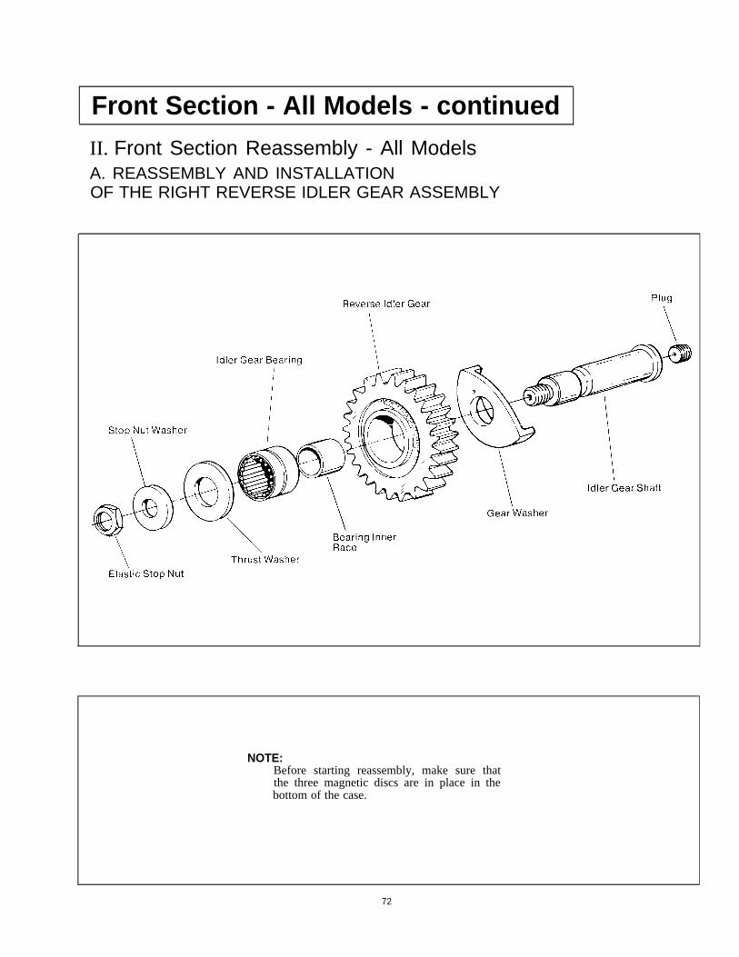
II. Front Section Reassembly - All ModelsA. REASSEMBLY AND INSTALLATIONOF THE RIGHT REVERSE IDLER GEAR ASSEMBLY
NOTE:Before starting reassembly, make sure thatthe three magnetic discs are in place in thebottom of the case.
72

1. Install the plug in the end of the shaft and install thecup and bearing inner race on the shaft.
3. Install the gear and thrust washer on the shaft as theshaft is inserted into the bore. Make sure that the longhub of the gear (arrow), faces towards the front of thecase .
4. Install the elastic stop nut and washer on the shaft.Install the auxiliary countershaft front bearing outerrace in the reverse idler bore.2. Press the bearing in the bore of the gear.
73

Front Section - All Models - continued
II. Front Section Reassembly - All ModelsB. REASSEMBLY AND POSITIONING OF THE COUNTERSHAFT ASSEMBLIES
NOTE:NOTE:
Except for the number of teeth on the PTOgears, the countershaft assemblies are iden-tical.
I t i s recommended that the proper I l lus t ra tedPar t s L i s t be used du r ing r eas sembly o f t hec o u n t e r s h a f t a s s e m b l i e s t o p r o v i d e t h eproper gear part numbers and locations.
74

3. Press the second speed gear on the shaft, long hubu p .
1. If previously removed, install the roll pin, woodruffkey and long key on each shaft.
2. Press the first speed gear on the countershaft, longhub down.
4. Press the third speed or overdrive gear on the shaft,long hub down.
75

Front Section - All Models - continued
II. Front Section Reassembly - All ModelsB. REASSEMBLY AND POSITIONING OF THE COUNTERSHAFT ASSEMBLIES
7. Place the left countershaft into position in the case, butdo not install bearings. make sure the left countershafthas the larger 47-tooth PTO gear.
5. Start the PTO gear onto tile shaft with the roundedside of- the teeth facing up. Install the drive gear on theshaft with the long hub facing up and press the PTO anddrive gears into position. Install the spacer on the shaftnext to the drive gear.
8. Place the right countershaft into position in the case,but do not install bearings. Make sure that the rightcountershaft has the smaller 45-tooth PTO gear.6. On the drive gear of each countershaft, mark the gear
tooth which aligns with the keyway in the shaft. Thistooth will be stamped with an "O".
NOTE: The left-side countershaft takes a 17-tooth PTOgear; the right side countershaft takes a 15-tooth PTOgear.
7 6

C. REASSEMBLY AND INSTALLATION OF THE DRIVE GEAR ASSEMBLY
1. If previously removed, install the snap ring in the IDof the drive gear and instal l the drive gear on thesplines of the shaft, snap ring towards the front.
5. Install the drive gear nut on the shaft threads using250-300 lbs.-ft. of torque. Peen the nut into the twoslots on the shaft.
2. Install the spacer on the shaft and against the snapring.
6. Mark any two adjacent teeth on the mainshaftdrive gear and ten mark the two teeth directly oppo-site. Check to make sure that the bushing is in place inthe shaft pocket and in good condition. If the bushinghas to be replaced, install the new bushing flush intothe shaft pocket.
3. Press the drive gear bearing on the shaft with theshield to the front.
4. Clean the threads on the shaft and the drive gear nut.Apply Loctite, grade AVV to the threads of the drivegearnut.
7. Remove the snap ring from the bearing and insertthe drive gear assembly through the bore from insidethe case, working past the countershafts to seat thebearing in the case boare. Re-install the snap ring in theOD of the bearing.
77

Front Section - All Models - continued
II. Front Section Reassembly - All ModelsD. TIMING AND INSTALLATION OF THE LEFT COUNTERSHAFT ASSEMBLY
1. Place a centering tool or wood blocks in the casebore to center the rear of the countershaft.
2. Mesh the marked tooth on the countershaft drivegear between two of the marked teeth on the mainshaftdrive gear.
3. Install the front bearing in the bore and on the shaft.
4. Remove the blocking and install the rear bearing.
5. Install the retainer plate on the front bearing with thetwo lockscrews; wire securely.
6. install the snap ring in the groove at the rear of theshaft.
78

SETTING CORRECT AXIALCLEARANCESFOR MAINSHAFT GEARS
Axial Clearance (End Play) Limits Are:Reverse speed gear - Minirnum of .005"
Forward speed gears - .005" to .012"
Washers are used to obtain the correct limits; six thick-nesses are available as follows:
LIMITS COLOR CODE
.248 -.250 White
.253 -.255 Green
.258 -.260 Orange
.263 -.265 Purple
.268 -.270 Yellow
.73-.275 Black
Refer to Illustrated Parts Lists for washer part numbers.(See page 3).
Always use the low limit washer in the LOW GEARand 2nd SPEED GEAR positions as shown tit right. Referto the service manual covering mainshaft reassembly formethod of assembling parts.
Reverse gear clearance must be set as low as possible to theminimum .005". Clearance can be measured before themainshaft assembly is installed in the case. This is done bysecuring the reverse gear in position on mainshaft with thereverse gear snap ring and the front snap ring; then. se-cure auxiliary drive gear assembly in position at rear ofmainshaft with the rear snap ring. (See page 84. )
**The "LOW", "lst", "2nd" and "3rd" speed gear designa-tions are the nomenclatures for 9- and 13-speed directmodels. Gear speeds shown in parentheses are nomencla-tures for 10- and 15-speed direct models.
79

Front Section - All Models - continued
II. Front Section Reassembly - All ModelsE. REASSEMBLY AND INSTALLATION OF THE MAINSHAFT ASSEMBLY
1. If previously removed, install a snap ring in the IDof all mainshaft gears except for the reverse gear. Makesure that the roll pin is in place in the bore betwccnthe mainshaft splines. The key bottoms against thisroll pin during reassembly.
NOTE:It is recommended that the proper lllustratedParts List be used during reassembly of themainshaft to provide the proper gear, washerand spacer part numbers and locations.
2. Secure the mainshaft in a vise with the pilot enddown. Do not secure the shaft by the pilot. Install aLow Limit washer as shown with the flat surface up.Secure the washer with the key.
NOTE:When installing washers make sure that thelarge notch on the internal splines is awayfrom the keyway.
3. Install the spacer on the washer, flat surface down.
4. Install the third speed or overdrive gear on the spacer,clutching teeth down.
80

5. Install the second speed gear, clutching teeth up.
6. Install the spacer in the hub of the gear, flat surfaceup.
7. Remove the key and install washer with the flatsurface down. Turn the washer in the hub of the gearto align with the mainshaft splines, using caution notto turn the gears on the shaft. Use the proper washerto obtain the correct end play. This should be checkedwith a feeler gauge between the gear hubs. Re-installthe key in the keyway.
8. Install the sliding clutch with the keyway over thekey.
31
Front Section - All Models - continued
II. Front Section Reassembly - All ModelsE. REASSEMBLY AND INSTALLATION OF THE MAINSHAFT ASSEMBLY
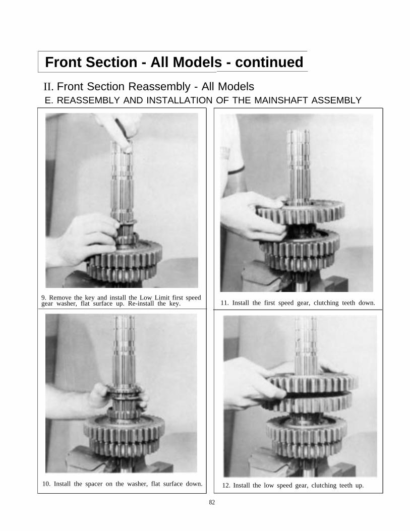
9. Remove the key and install the Low Limit first speedgear washer, flat surface up. Re-install the key. 11. Install the first speed gear, clutching teeth down.
10. Install the spacer on the washer, flat surface down. 12. Install the low speed gear, clutching teeth up.
82

13. Install the spacer in the hub of the gear, flat surfaceup.
16. Install the reverse gear over the clutch and engag ethe clutch in the low speed gear so that the two gearsare against each other .
14. Remove the key and install the washer, flat surfacedown. Turn the washer in the gear hub to align thesplines with the mainshaft. Re-install the key and checkend play between the gear hubs. 17. Remove the key and install the reverse gear washer,
f l a t s u r f a c e u p . R e - i n s t a l l t h e k e y .
15. Install the sliding clutch, aligning the keyway overthe key. 18. Install the spacer, flat surface down.
83

Front Section - All Models - continued
II. Front Section Reassembly - AH ModelsE. REASSEMBLY AND INSTALLATION OF THE MAINSHAFT ASSEMBLY
19. Install the snap ring in the indicated position with theopening over the key.
20. Remove the assembly from the vise and install thesliding clutch.
21. From inside the case, insert the rear of the main-shaft through the rear bearing bore and lower theassembly into position. Block the right countershaftagainst the side of the case and move the mainshaftpilot forward to scat in the pocket of the drive gearshaft.
Setting Reverse Gear End-play Limits
After setting the correct axial clearances for the mainshaft forward speed gears (see page 79), secure the mainshaftassembly in a vise with the front end down. Install the snap ring in the hub of the reverse gear and install the gear on theshaft in its proper position with the clutching teeth facing down.
Install the auxiliary drive gear assembly on the shaft in its proper position and secure the assembly to the shaft with the rearmainshaft snap ring. (Photo A)
Insert two screwdrivers between the auxiliary drive gear and the reverse gear and pry upwards. Insert a feeler gauge betweenthe hubs of the reverse gear and the auxiliary drive gear to check clearance. (Photo B)
Use the chart on page 79 to determine the correct washer to use to bring the clearance as close as possible to theminimum .005".Remove the auxiliary drive gear. Remove the snap ring from the hub of the reverse gear and allow the gear to rest on the firstspeed gear. Replace the reverse washer on the shaft with the correct thickness washer and proceed with the reassembly.
84

F. TIMING AND INSTALLATION OF THE RIGHT COUNTERSHAFT ASSEMBLY
4. Install rear bearing on countershaft and in case bore.1. Mesh the marked tooth on the countershaft drivegear between the two marked teeth on the mainshaftdrive gear making sure that the left countershaft re-mains in time.
5. Install retainer plate on front of countershaft andwire securely.
2. Center the rear of both the mainshaft and counter-shaft in the case bores. Accurate centering of the main-shaft is important. Partially install the auxiliary drivegear assembly to center the rear of the mainshaft.
3. Install the front bearing on the countershaft and int h e c a s e b o r e .
6. Install snap ring in groove at the rear of the counter-s h a f t .
85

Front Section - All Models - continued
II. Front Section Reassembly - All ModelsG. REASSEMBLY AND INSTALLATIONOF THE LEFT REVERSE IDLER GEAR ASSEMBLY
1. Install the plug in the end of the shaft and slide thecup and bearing inner race on the shaft.
2. Press the needle bearing in the bore of the gear.
3. Place the thrust washer and gear into position makingsure that the long hub of the gear faces toward the frontof the case. Insert the shalt through the gear and into thebore and seat the shalt in the bore, making sure that theneedle bearing is aligned with the inner race.
4. Install the washer and nut on the shaft.
5. Seat the outer race of the auxiliary countershaft frontbearing in the reverse idler bore.
6. Mesh the mainshaft reverse gear with the reverse idlergears and install the snap ring in the ID of the mainshaftreverse gear.
86

H. REASSEMBLY AND INSTALLATIONOF THE AUXILIARY DRIVE GEAR ASSEMBLY
1. Place the retainer ring on the gear with the flat sur-face of the ring against the gear.
2. Press the bearing on the drive gear with the snapring facing up.
3. Install the snap ring in the groove in the gearshoulder.
4. Seat the bearing in the rear bore, fitting the gear onthe mainshaft splines.
5. Secure the assembly with the six lockscrews; wire ingroups of three.
6. install the snap ring in the mainshaft groove.
87

TORQUE RECOMMENDATIONS
88

89
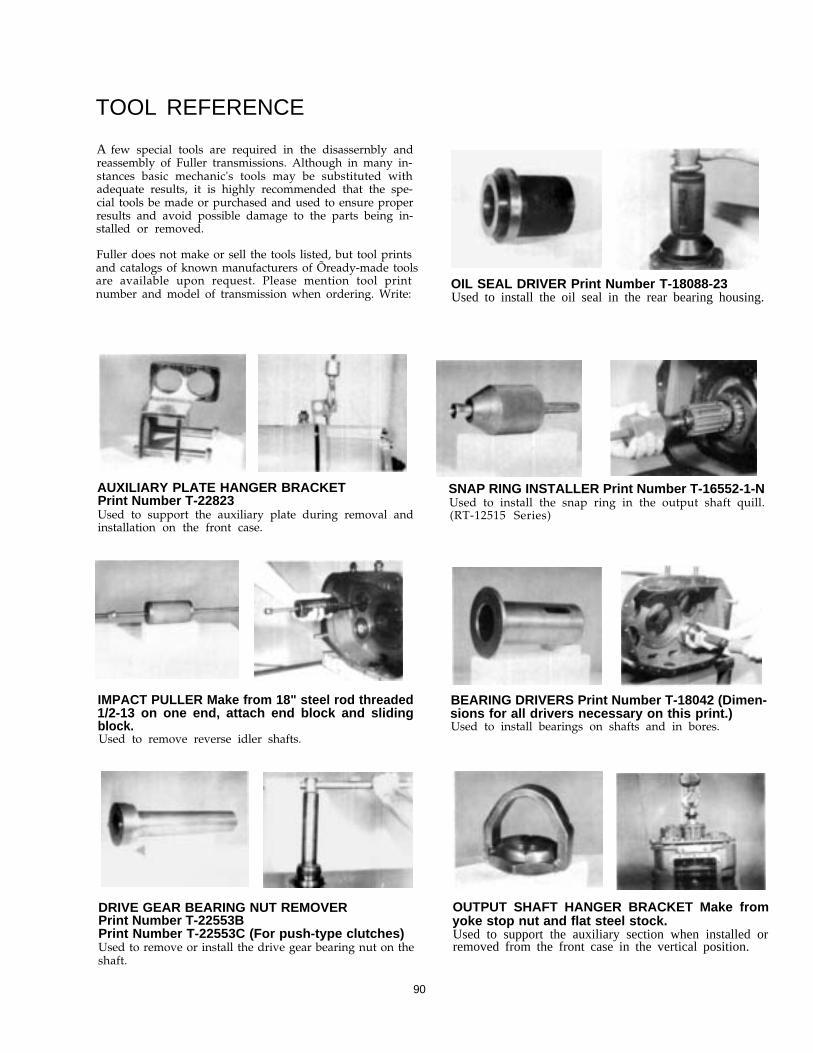
TOOL REFERENCE
A few special tools are required in the disassernbly andreassembly of Fuller transmissions. Although in many in-stances basic mechanic's tools may be substituted withadequate results, it is highly recommended that the spe-cial tools be made or purchased and used to ensure properresults and avoid possible damage to the parts being in-stalled or removed.
Fuller does not make or sell the tools listed, but tool printsand catalogs of known manufacturers of Õready-made toolsare available upon request. Please mention tool printnumber and model of transmission when ordering. Write:
AUXILIARY PLATE HANGER BRACKETPrint Number T-22823Used to support the auxiliary plate during removal andinstallation on the front case.
OIL SEAL DRIVER Print Number T-18088-23Used to install the oil seal in the rear bearing housing.
SNAP RING INSTALLER Print Number T-16552-1-NUsed to install the snap ring in the output shaft quill.(RT-12515 Series)
IMPACT PULLER Make from 18" steel rod threaded1/2-13 on one end, attach end block and slidingblock.Used to remove reverse idler shafts.
BEARING DRIVERS Print Number T-18042 (Dimen-sions for all drivers necessary on this print.)Used to install bearings on shafts and in bores.
DRIVE GEAR BEARING NUT REMOVERPrint Number T-22553BPrint Number T-22553C (For push-type clutches)Used to remove or install the drive gear bearing nut on theshaft.
OUTPUT SHAFT HANGER BRACKET Make fromyoke stop nut and flat steel stock.Used to support the auxiliary section when installed orremoved from the front case in the vertical position.
90

SPECIAL PROCEDURE FOR CHANGING CLUTCH (INPUT) SHAFT
In some cases in field repair it may be necessary toreplace only the input shaft due to clutch wear on thesplints.
In these instances the input shaft can be removedwithout disassembling the transmission other than re-moving the shifting bar housing. Removal of the clutchhousing is optional. Following is the detailed procedure:
Disassembly
1. Remove gear shift lever housing and shift bar housingfrom transmission.
2. Remove the front bearing cover.
3. Engage the mainshaft sliding clutches in two gears andremove the drive gear bearing nut.
4. Move the drive gear assembly as far forward as pos-sible and remove the drive gear bearing.
5. Remove the washer from input shaft.
6. From the front, remove the snap ring from ID of drivegear.
7. Pull the input shaft forward and from splines of drivegear.
Reassembly
1. Install new input shaft into splints of drive gear justfar enough to expose snap ring groove in ID of drivegear.
2. Install snap ring in ID of drive gear.
3. Install washer on shaft.
4. Move the fourth-fifth speed sliding clutch gear forwardto contact end of input shaft in hub of drive gear. Blockbetween rear of sliding clutch and front of the fourthspeed gear. When installing bearing this will hold inputshaft in position to scat the bearing properly.
5. Install drive gear bearing on shaft and into case bore,making sure blocking remains in place.
6. Remove blocking from mainshaft and install the drivegear bearing nut, left-hand thread. Use Loctite sealanton threads of nut and shaft.
7. Peen nut into milled slots in shaft.
8. Re-install front bearing cover, shifting bar housingand gear shift lever housing.
NOTE:The above instructions are or changing the input shaftonly. To change the drive gear, complete disassembly ofthe front section must be made.
91

Copyright Eaton Corporation, 2012. Eaton hereby grant their customers, vendors, or distributors permission to freely copy, reproduce and/or distribute this document in printed format. It may be copied only in its entirety without any changes or modifications. THIS INFORMATION IS NOT INTENDED FOR SALE OR RESALE, AND THIS NOTICE MUST REMAIN ON ALL COPIES.
Note: Features and specifications listed in this document are subject to change without notice and represent the maximum capabilities of the software and products with all options installed. Although every attempt has been made to ensure the accuracy of information contained within, Eaton makes no representation about the completeness, correctness or accuracy and assumes no responsibility for any errors or omissions. Features and functionality may vary depending on selected options.
For spec’ing or service assistance, call 1-800-826-HELP (4357) or visit www.eaton.com/roadranger.In Mexico, call 001-800-826-4357.
Eaton CorporationVehicle GroupP.O. Box 4013Kalamazoo, MI 49003 USA800-826-HELP (4357)www.eaton.com/roadranger
Printed in USA
Roadranger: Eaton and trusted partners providing the best products and services in the industry, ensuring more time on the road.