Full Line Product Information - Radio Works
64
Antenna Trimming Chart - 60 Installing Antennas in Trees - 20 Tower Installation - 32 Ground Loop Solution - 13 Installing Line Isolators - 16 Power & Control Line Isolators - 18 RF Ground Systems - 7 Second Floor Grounding - 15 Ultimate Sealing Technique - 4 Weatherproofing - 3 Installation Checkoff Lists - 26 Copyright © 1997, 1999, 2002, 2003, 2006 All rights reserved Full Line Product Information Box 6159, Portsmouth, VA 23703 U.S.A. 757-484-0140 FAX 757-483-1873 WEB Site http://www.radioworks.com Inverted-V Before installing your antenna as an inverted-V, read page 61. IMPORTANT - Read pages 2 - 4 and all related instructions before beginning any installation!
Transcript of Full Line Product Information - Radio Works

Antenna Trimming Chart - 60
Installing Antennas in Trees - 20
Tower Installation - 32
Ground Loop Solution - 13
Installing Line Isolators - 16
Power & Control Line Isolators - 18
RF Ground Systems - 7
Second Floor Grounding - 15
Ultimate Sealing Technique - 4
Weatherproofing - 3
Installation Checkoff Lists - 26
Copyright © 1997, 1999, 2002, 2003, 2006 All rights reserved
Full Line ProductInformation
Box 6159, Portsmouth, VA 23703 U.S.A.
757-484-0140
FAX 757-483-1873
WEB Site http://www.radioworks.com
Inverted-VBefore installing your antenna as
an inverted-V, read page 61.
IMPORTANT - Read pages 2 - 4
and all related instructions before
beginning any installation!
CAUTION
Read This TextThis page is included to help you make your antenna installation safe. The followingcautions are general, and they apply to all antenna and balun installations; they are notspecific to any RADIO WORKS antenna, balun, or accessory.
HAZARDS This antenna or antenna component is USER INSTALLED. TheRADIO WORKS has no control over its installation. Before you begin, youmust be qualified and must be fully aware of the CONSEQUENCES andDANGERS involved in antenna, balun and transmission line installations.
If you are not totally familiar with SAFE antenna and baluninstallation practices, GET COMPETENT HELP and ADVICE beforeinstalling this antenna, antenna part or accessory.
POWER LINES DO NOT build, erect or install any antenna or tower (or part of anantenna, such as a balun or transmission line) near POWER LINES,POWER POLES, OR ANYTHING ASSOCIATED WITH THEM. THISINCLUDES THE POWER LINES THAT RUN FROM A POWERPOLE TO A BUILDING. Mount your antenna so that it CANNOT fall (orbe blown by high winds) into power lines.
LIGHTNING LIGHTNING is providential, and provisions must be made for it. Useappropriate LIGHTNING protection, and install it following theinstructions supplied with the device. Also, disconnect all your antennasfrom your equipment and disconnect your equipment from the power linesduring weather that is likely to produce lightning.
SHOCK HIGH VOLTAGE may exist on certain parts of antennas, baluns, andtransmission lines. This represents a possible SHOCK or FIRE HAZARD!It is not a fault of the design or the designer. It is a consequence of thephysical laws involved. Most antennas will develop HIGH VOLTAGE atsome point on their physical structure. HIGH VOLTAGE can occur insome antenna types even when applying low RF power. Be certain thatyour antenna installation provides for this POTENTIAL HAZARD. Locateall parts of the antenna well out of the reach of people. It is also desirableand proper installation practice to keep all antenna components away fromany object not made of insulating material.
The RADIO WORKS Box 6159 Portsmouth, VA 23703
2

WARNING!PROTECT YOUR WARRANTY!
THE ENCLOSED CoaxSeal® MUST BE USED AND APPLIED CORRECTLY.
Most weatherproofing techniques used by Hams are not reliable. Occasionally, acustomer returns an antenna or balun that no longer works properly. In nearly every case, theproduct had not failed. Connectors or coaxial cable had failed as the result of improperlyapplied weatherproofing. Often, no weatherproofing was used! Nearly all failures have beentraced to corroded connectors and moisture contaminated coax.
As a service to our customers, we are including CoaxSeal® with each product.
Applying CoaxSeal®
1. Make sure the coaxial connector and thecoaxial cable are clean and dry.
2. Peel approximately five (5) inches ofCoaxSeal® from its paper backing. Startwinding from the coax jacket towards theconnector. Allow one-half overlap with eachwinding, making sure all joints are wellcovered. This is shown in the illustration,“STEP 1 & 2.”
3. After the entire connector and coaxial cable arecovered with 3/16" layers, mold and form theCoaxSeal® with your fingers to make a smoothsurface and to force out any air. CoaxSeal®
must stick to the connector and coax’s jacket.See illustration “STEP 3.”
4. If more CoaxSeal® is necessary to complete theseal, simply cut the needed amount from theroll and add it to the existing CoaxSeal®. Moldand press into the other material. CoaxSeal®
sticks to itself with slight pressure.
5. Carefully inspect the seal to make certainthat all openings are covered and sealed.
Baluns, Line Isolators, and MatchingTransformers are filled with a sealingcompound. However, to prevent any moisturefrom entering the case, apply CoaxSeal® to fillthe holes where wires exit the balun’s ormatching transformer’s case.
Pull lightly on each of the two wires to be surethey are fully extended out of the case. Peel asmall piece of CoaxSeal® from its paper backing.Ball up this CoaxSeal® and press around one ofthe wires where it exits the case. Press andmold the CoaxSeal® so that it sticks to the caseand to the wire’s jacket.
Repeat for the second wire on the opposite side ofthe case.
Inspect for complete sealing.
Again, pull LIGHTLY on each wire to be sure thatthe seal is secure.
It is not necessary to seal theeyebolts. Seal only the wiresexiting the case and thecoaxial connector.
3
* If any other weather sealer or weatherproofing technique is used with any RADIO WORKSproduct or if the CoaxSeal® is not installed according to directions, the warranty is void.

You need Coax Seal, STUF, Cold-shrink and electrical tape
Apply STUF to theconnector as shown.
When connector is tightened, “STUF”is compressed and forced to fill anyvoids in the connectors. Moisture andexcess STUF is forced out.
Ultimate Sealing TechniqueAll sealing products are available at the RADIO WORKS.
Compression causes STUF to fill all cavities and voids inside theconnectors. Since all voids are filled with STUF, a Teflon dielectricmaterial, any path for moisture reentry is eliminated.
ImportantClean off excess STUF
Overlap a layer of electrical tapefrom body of the device and continuewell on the cable.
A layer of quality electrical tapeis carefully applied in overlap-ping layers. The PL-259 connec-tor is completely covered from thebalun case (or other surface) toat least 1” on the coaxial cable.
Apply one overlapping layer ofCoax Seal. Press so that it sticksto the device and covers at least 1”of cable. The seal must be solidfrom device to cable.
IMPORTANT - Make sure theCoax Seal is well whetted (stuck)to the device as well as to the cable.
Optional, but recommended, applya layer of Cold-shrink tape com-pletely over the Coax Seal.
You should enjoy years of trouble-free service from this sealingtechnique.
4
STUF seals from the insideElectrical Tape makes removal of the Coax Seal easier and formsthe next layer of protection.Coax Seal provides a totally waterproof sealCold-Shrink Tape is a tough, solid outer layer which puts a squeez-ing force on the Coax Seal to improve the seal. It provides an extralayer of protection.
Cover the Cold Shrink with a layer of electrical tape

The RADIO WORKS Box 6159 Portsmouth, VA 23703
5
Important - Power RatingsCheck the Specs Most products are rated at 1500 watts peak output on CW and SSB
under normal amateur radio duty-cycles. Antennas, baluns, and Line Isolators are not rated for
AM, FM, RTTY, or other high duty-cycle modes unless specifically rated for those modes in the
specifications.
Baluns and Line Isolators
All RADIO WORKS’ products’ power ratings are for standard Amateur Radio SSB and CW duty-cycles. Normally,that is 25%, which equates to 25% transmitting time followed by 75% listening time. Often these numbers are evenmore conservative in actual amateur service. We do not rate any of our products for high duty-cycle modes. Thisincludes AM, FM, RTTY and high duty-cycle digital modes. Essentially, these modes require devices designed forcommercial service. I have checked on prices for a commercial 2 kW balun and the price was nearly $1500. This iscertainly beyond the range of most of our budgets. I know that there are balun manufacturers that claim very highpower ratings. However, they say nothing about duty-cycle nor do they mention the load conditions under which theywill survive their rated power. I am being up-front with our ratings.
It has been only during that past five years that the interest in very high power operation has been more than a veryisolated case. We have been building baluns and Line Isolators for nearly two decades, and our power ratings weremore than adequate. Most operators were using SSB and CW. Most still operate those modes. Then came theresurgence of AM operation and the apparent disregard of power limits. For example, an AM transmitter generating1500 watts of carrier produces 6 dB higher output when fully modulated. In other words, the 1500 watt transmitterdelivers 6000 watts of modulated RF to the antenna components. That’s for a fully plate modulated carrier. Thelegal limit is 375 watts of carrier, by the way. That results in 1500 watts of modulated output.
The operating style of AM, FM and most RTTY operators, especially when contesting or when just being long-winded,is to run key-down for long periods of time. The same goes for the new digital modes. There is no cool-down time forantenna components. Another problem with older transmitters which run “class-C” output stages is the very highharmonic and spurious signal components in the output signal. Some antenna components, among them, high qualitycurrent baluns and Line Isolators, absorb much of the harmonic and spurious energy. This can result in core saturationand excessive heating. You may say that this doesn’t happen in other types of devices. The reason is that thesedevices just pass the harmonics and spurious signals along to the antenna. This isn’t to say that current baluns andLine Isolators can be used as “low pass filters.” Special devices are needed for that purpose. Each has its ownfunction and they should be used together.
PSK-31 operation is OK, and our baluns and Line Isolators will not contribute to distortion products or increasingyour IMD. Just keep the power in the 100 watt range.
I have to mention the PSK-31 operators. While PSK-31 is a high duty-cycle mode, nearly every operator I’ve heard onthe bands runs low power and gets through just fine. One reason for this is that PSK-31 operators are very conscien-tious about keeping their IMD products low. They reduce power until their rigs produce a clean signal. I wish thisconcern for clean signals would spread throughout operators of other modes. Perhaps if our receivers had an IMD or“distortion” meter, things would change.
AntennasThe matching transformers and Line Isolators used in our antenna systems are based on the same designs and partsused in our baluns and undedicated Line Isolators. Therefore, all of the above information on power limits applies toour antenna systems, too.

The RADIO WORKS Box 6159 Portsmouth, VA 23703
6
The checkoff lists start on page 26, following the complete general installation instructionson page 20. These lists are step-by-step installation guides. Use them. They are specificand detailed. Also, pay attention to the “Do’s and Don’ts” list on page 25.
For maximum life and performance from your antenna, do not assume that the “InstallationCheckoff Lists” are not important.
If your antenna is not installed properly, it will not perform properly!
If you call with questions about your antenna installation, we use the lists to help identifyany problems with your antenna system. In 99% of the calls, the problems could havebeen avoided if these instructions had been followed.
CAUTIONKEEP ANTENNAS AWAY FROM ELECTRIC UTILITIES
An RF ground is very important. See the grounding information in this productmanual starting on page 7.
DO NOT use your house ground system as your radio ground system. This is sureto cause RFI and even more serious problems. Do not use water pipes for grounds.
If your radio room is not on the ground floor where very short ground runs arepossible, you will probably have RFI and RF feedback problems with any antennasystem. The solution is to install ground mounted and in-station Line Isolators.Use a “single-point” ground system and run multiple ground runs. See page 15.
IMPORTANTDo Not Ignore the Installation Checkoff Lists

The RADIO WORKS Box 6159 Portsmouth, VA 23703
7
From the telephone calls we receive, many of youare having problems with RF ground systems. RFground? Yes, most of us have ground systems thatprovide adequate DC grounding. Unfortunately, a goodDC ground system may not be a good RF ground system.In fact, you may have an ‘UN-GROUND.’ UN-GROUND? Absolutely. There are situationswhere your ground system may actually un-ground yourstation. The reason lies in the fundamental differencebetween DC and RF circuits.
DefinitionIMPEDANCEThe total opposition (resistance and reactance) acircuit offers to the flow of alternating current.Impedance is measured in ohms. The commonsymbol is Z.
DefinitionREACTANCESymbolized by X, it is the opposition to the flow ofalternating current. Capacitive reactance (XC) is theopposition offered by capacitors and inductivereactance (XL) is the opposition offered by a coil orother inductance. Both are measured in ohms.
Any wire will have inductance and therefore, inductivereactance. The longer the wire, the higher the inductivereactance and the higher the opposition to the flow of RFcurrent. The fatter or larger the wire, the lower theopposition to the flow of RF current. The effect is similar tothe DC resistance of a wire. The longer the wire, the higherthe DC resistance will be. The fatter the wire the lower the DC resistance for thesame length wire. There is an important ‘however,’ thatwe must consider. When the XL (inductive reactance) ismeasured along the length of a wire, the magnitude of XL
(the opposition to RF current flow) varies from very low tovery high values. It continues to alternate between lowand high values in cycles that have a direct relationshipbetween the length of wire and the frequency of the appliedRF energy. DC resistance, on the other hand, has no cycle.It simply increases linearly with the length of the wire. When measuring XL, its value is very high when thelength of the wire is around one-quarter wavelength long.Increasing the length wire to one-half wavelength, returnsXL to a low value. The length of the wire does not have to be very long forthis effect to be observed. For example, at 28 MHz an 8'ground wire (or any wire for that matter) is approximatelyone-quarter wavelength long. If this 8 foot long ground wireconnects your 10 meter rig to may actually prevent RF fromtraveling to ground. This is an UN-GROUND!
RF GROUND SYSTEMSThe UN-GROUND . . . .
Ground systems that aren’t ....
Why? As illustrated above, the inductive reactance ofwire that is one-quarter wavelength long is very highand impedes RF current flow (thus the term -impedance).
On other bands, where the length of the wireis not an odd multiple of a quarter wavelength long,the inductive reactance (XL) is at some intermediateor low value.
High RF VoltageFigure 2 shows a grounding diagram
of a typical ham station.There is a heavy ground strap running along the backof the equipment. The ground strap eventually reachesthe earth ground system, a ground rod, through a heavygauge copper wire 11 feet in length. The groundconnection for each piece of equipment goes directly tothe heavy ground strap that runs behind the stationequipment. The antenna is a ladder-line fed, 80meter dipole used on all bands. The ladder line isbrought directly into the operating position where itconnects to the balanced output of the tuner(transmatch). The ladder line is about 60 feet long andgoes directly to the antenna, but passes very close to ametal rain gutter. Such a station should be effectiveand trouble free. Unfortunately, this station isexperiencing problems on several bands. There is RFfeedback distorting the transmitted signal, and thereare some TVI and RFI problems. What could be wrong?

The RADIO WORKS
Transmitter Linear Amp Transmatch
Ls
Earth Ground
Ground Loop Ground Loop
Ground Bus
Coax Coax
If we tune up on 20 meters, the 80 meterdipole becomes a center-fed, two wavelength antenna.The feedpoint impedance is around 4500 ohms. Thelength of the ladder line feeding the antenna is aboutone wavelength long. It is a characteristic oftransmission line that it will duplicate its loadimpedance every half-wave along its length. So, thevery high antenna feedpoint impedance appears rightat the tuner’s (transmatch) output terminals.However, before reaching the tuner (transmatch), theladder line runs very close to a metal rain gutter.Feedline balance is upset, and it begins to radiate atthat point.
The tuner (transmatch) uses a voltage-typebalun to create a balanced output. Baluns do not workwell in high impedance circuits, and voltage-typebaluns are especially bad in this application.With a high impedance load, the voltage balun’s corewill saturate even at moderate power levels. Outputbalance is poor.* This contributes to additionalradiation from the balanced line.
In this illustration, we have several problems,each compounding the other. First, all of the groundsystem and ground loop problems still exist, but wenow have a tuner (transmatch) balun that issaturating and generating high level harmonics.Signal distortion may be noticeable because the balunis no longer operating in its linear region. The ladder-line is not balanced so it radiates, and the equipmentat the operating position becomes part of the antennasystem. Here is a real shocker! There is RF allover the equipment. The Microphone is biting yourlips. Your computer crashed. The packet TNC willnot talk to you anymore, but none of this mattersbecause the station power supply shut itself down andyou are off the air. Sound impossible? Unfortunately,it’s not. This is a true story and this isn’t the end.
* Voltage-type baluns provide their best balance whenfeeding matched loads. Current baluns provide betterbalance under most conditions.
HIGH ABOVE THE GROUNDThe ground wire is about 11 feet long. On 15meters, this length is almost exactly 1/4 wavelength
A length of wire or coax that is 1/4 wavelength longis an impedance inverter. One end is at low impedance, sothe other end presents a high impedance to the circuitconnected to it. In other words, the ground wire is near zeroimpedance at the ground end, but due to the impedanceinverting characteristic, the station equipment ‘sees’ a veryhigh impedance at the equipment end of the ground wire. Ineffect, the equipment is UNGROUNDED at high RFfrequencies.
On 20 meters, the 11 foot ground wire is .15wavelengths long. Referring to figure 1 and interpolatingbetween zero and 1/4 wavelength, the inductive reactance ofthe ground wire is still quite high. To our station equipment,the ground wire simulates an inductive reactance in serieswith the resistance of the ground wire. This is illustrated bythe coil LS in figure 2. We’ll disregard the DC resistance ofthe ground wire.
Without getting into great detail, let’s just agree thatit would be better if the station had a direct, low impedancepath to ground. In this illustration, this is not the case. Thepath to ground is a high impedance on the higher frequencybands. In fact, there are alternate grounds available to thestation equipment. Other, undesirable, ground paths maypresent a lower impedance path to earth or may act as acounterpoise. Unfortunately, one of those ground systems isthe electrical power lines at the operating position. RF fromthe transmitter, seeking a ground path, may have to pass byor through several electronic appliances (TVs, VCRs, etc.)that would work better if they were isolated from yourtransmitting equipment.
Due to the inductive reactance of the ground system,none of the equipment in this station is effectively groundedon the higher HF bands. If an RF potential exists on thestation ground system, the entire station may ‘float’ up tothat RF potential. Thus, the earth ground reference isactually several volts above ground. All sorts of RFI problemscan be the result, including RF feedback into stationmicrophones, computers, monitors, TNCs, power supplies,etc.
Solid state equipment is especially sensitive toground problems.
Solid state equipment is especially sensitive to groundproblems. Each piece of equipment in figure 2 isinterconnected by two ground paths, a ground strap and thecoaxial cable that interconnects the equipment. The twopaths form a ground loop. Since there is high system gaininvolved from the millivolts of the transceiver’s input circuitsto the kilovolts of the linear’s output circuit, ground loopscan be a serious problem. It’s even worse if the ground systemis ineffective and the entire station is ‘floating’ above ground.Breaking the ground loops can lead to the solution to longunsolved RFI problems.
The RADIO WORKS’ Line Isolatorstm are veryeffective at solving ground loop problems.
8

The RADIO WORKS
The Shocking TruthHave you evercalculated what thevoltage across a 4500ohm reactive load isat 1.5 KW? It is morethan a few volts.Actually, it’s a fewthousand volts. It’sunbalanced, and it’slooking for somewhereto go. As we predictedin previousp a r a g r a p h s , t h eantenna feedpointimpedance andcorresponding high RFvoltage is transferreddirectly across theoutput terminals of the tuner (transmatch). Severalthousand volts of RF is only a few feet away and at RF,the station is poorly grounded.
I’m not going to boreyou with a lot of math, butlet’s simplify this situation toa simple series circuit. Infigure 3, the antenna, tuner(transmatch), and groundsystem are represented by asimple voltage divider. Thissimple circuit will allow meto illustrate what ishappening to the ground busin the ham shack.
First, let’s assumethe voltage at point ‘A’ on thetuner (transmatch) is 500volts. It is really muchhigher. The impedance atthe output terminals of thetuner (transmatch) is 4500 ohms, and the reactance ofthe ground system is 500 ohms. I did not calculate thevalue for the ground system, the 500 ohm value is forillustration.
Reducing the problem to its simplest terms, wehave a 4500 ohm resistor in series with a 500 ohm resistor.The ground system is the tap between the two. In thisexample, if there are 500 volts at the tuner (transmatch),the station ground system will ‘float’ above earth ground.The potential is about 50 volts. Your ground system andall your equipment, in effect, has 50 volts of RF appliedto the equipment grounds. This is just like having a50 volt input signal if the input circuits were at groundpotential.
Another way to look at this problem is to visualizethe antenna and ground system as a big coil that representthe inductive reactance of the ground system and tuner(transmatch). The antenna is at one end of the coil, andthe ground is at the other. We are tapped several turnsup the coil. The higher the impedance of the groundsystem, the higher up the coil the ‘tap’ is located. Theonly way to keep RF off the station equipment and stationground is to move the point were the rig is tapped intothe coil closer to ground.
Symptoms
There are some symptoms that may suggest the existenceof station grounding problems. A list must include suchobvious things as ‘mic bite,’ a tingly feeling when touchingmetal while transmitting. A less obvious symptom istransmitted signal distortion due to RF feedback. RFIand TVI problems can often be traced to groundingproblems. Here are a few other observations that werethe result of an UN-GROUND.
(1) Two SWR meters, one in your transceiver and thesecond in the tuner (transmatch) that are in widedisagreement. This assumes that both meters areacurate, your SWR is low and the interconnectingcoaxial cable is short.
(2) A change in indicated SWR when the stationground system is temporally disconnected fromall equipment.
(3) A change in indicated SWR reading after addinga 1/4 wavelength counterpoise in parallel with thestation ground system. Information on making acounterpoise is covered later in this chapter.
(4) Adding a Line IsolatorTM at the output of yourtransceiver changes the drive to your linear, altersmeter readings, requires changes in tuner(transmatch) settings or results in a differentSWR reading on either the transceiver’s or linear’swatt-meter.
If any of these observations suggest that there is a groundor ground loop problem, there are several things you cando. Eliminating a ground system problem may clear upboth existing and potential RFI problems.
Fortunately, under most circumstances we do not havesevere problems with our ground systems; still there maybe symptoms that go unnoticed.
Of course, it’s never this simple. My numbersare only representative, but they do serve as anillustration. The RF voltage on the station groundsystem does reach very high levels under somecircumstances. I have had hams tell me of severe RFburns and visible ‘arcing’ from microphones, equipmentchassis, ground busses. Obviously, at these levels of RFvoltage, there will be terrible problems. But, whathappens when the RF voltage on the ground system isonly a few volts? You may not know that RF energy isthere, causing RFI or other problems.
9

The RADIO WORKS
Box 6159 Portsmouth, VA 23703
The CureTracking down grounding problems is most often a te-dious process. Adopting a step-by-step approach will pro-duce the best results.
Here is one procedure you may want to try if you suspectyou are a victim of an UN-GROUND.
ProcedureUsing this procedure for hunting an UN-GROUND orsolving an RF feedback problem requires several (four toeight) 1/4" or ½” snap-together RFI cores or MFJ-701‘break-apart’ toroids. I suggest using our “snap-together”RFI cores first in each step. If you notice an improvement,try one or more MFJ-701 toroids so see if there is furtherimprovement.
After completing each step, reconnect power to therig, go on the air and see if the symptoms persist.Unless the symptom is eliminated, continue with eachsucceeding step.
[ ] Temporarily disconnect the ground wires from allequipment. Make sure that a shock hazard does notexist when doing this.
[ ] Disconnect all leads to ancillary equipment.[ ] Ground only the antenna tuner (tuner).[ ] Snap on two or more RFI cores or wrap the coax
that connects the transceiver’s output to the linearamplifier or tuner around one or more MFJ-701 coresfollowing the instructions supplied.
[ ] Reconnect the ground system, grounding each piece ofequipment independently to a single, central groundpoint. This will be your tuner, if one is used. If not,ground central is the last piece of equipment in line.It’s the one that connects to the antenna.
Having completed these steps, there should be anoticeable improvement in the symptoms previouslyobserved. If not, the problem is so severe that you willneed to follow the suggestions in one of the RFIhandbooks.
[ ] Remove the “snap-together RFI cores and the MFJ-701 toroids, one-by-one, making sure the problem doesnot return. This procedure will confirm the specificsource of the problem.
If a change in symptoms is observed when connectingor disconnecting the ground system, follow the suggestionsfor installing an effective RF ground system that follows.
If placing RFI cores or MFJ toroids on one or more ofthe coaxial cables that interconnect the transceiver, linear,and tuner (transmatch) is effective, install Line Isolatorstm
in place of the cores. The RADIO WORKS’ Line Isolatorstm
are much more effective than any practical number of RFIcores or toroids.
If placing MFJ cores on one or more controlinterconnect cables or power cables proves to be effective,permanently install the RFI cores or MFJ-701 toroids onthose cables.
In most installations, it is a good idea to install the ineIsolators even if grounding problems are not evident. TheT-4 series of Line Isolatorstm are very effective in RFIprevention.
The station ground must provide both effective DC andRF grounding. Creating a good DC ground is not a problem,but an effective RF ground must be carefully planned.
The ground system should generally follow thesesuggestions:
(1) The ground wire should be as short as possible,preferably much shorter than a quarter-wavelength long on the highest frequency bandoperated.
(2) The ground wire should be very large. Isometimes use the braid removed from a piece ofRG-213. Better yet, use one or more lengths of1/2" or 1" tinned braided strap. If you canmanage it, use 2" or 3" solid copper strap.
(3) Clamp this short, heavy ground wire to yourground rod(s) or radial system.
(4) Use several different lengths of ground wires inparallel, each connected to a separate groundrod. This provides multiple, parallel groundpaths.
GROUND SYSTEMS
SIMPLE - a single ground rod driven into the earth justoutside the ham shack.
INTERMEDIATE - Several ground rods, connected in parallelwith very heavy wire or braided strap.
[ ] Install RFI cores (it may require several) or wrap the power cords to all equipment around MFJ-701 cores.
Determine the effect of the following. Remember toevaluate any improvement in the RFI problem after eachstep.
[ ] Reconnect all ancillary equipment[ ] Reconnect the microphone[ ] Reconnect all control cables.
If the problem worsens when any cable is reconnected,first try the “snap-together” RFI cores and if any improve-ment is noted, install an MFJ-701 core or more “snap-together” ferrite cores, to see if further improvement isachieved.
10

The RADIO WORKS Box 6159 Portsmouth, VA 23703
11
ELABORATE, and very effective - 25 short (6-12")ground rods spaced approximately 4' apart andinterconnected in series by a 100' length of heavybraided or solid ground strap. This system is veryefficient. The original design used stainless-steel pegsfor ground rods and stainless steel wire to preventefficiency reducing corrosion. Copper will loose itseffectiveness over time, but it’s still worth the trouble.Regular ground system maintenance is necessary. Ihave installed one of these systems at my station andplan to install two more. I can say that this groundsystem, combined with grounded Line Isolators atground level and standard Line Isolators in the shackproduces exceptional results with significantimprovements in RF grounding, reduction of RFground loops and feedback. Plus, I noticed a majorreduction in receiver noise. I’ll have more informationon this system on page 18 and page 19.
SOLUTION - RF Grounds
What can we do? A lot, but all the explanations anddetails deserve an entire chapter or a good lecture atyour ham club. Here are a few quick suggestions:
(1) Lower the ground system impedance.a. Use multiple ground paths - two or more
ground runs from station ground central toearth ground via large gauge copper wire orstraps. Each run is a slightly differentlength. Each run terminates into one ormore ground rod or other ground system.
b. Install a radial systemc. Use heavier ground cable, braid, or strap.d. Shorten the ground wiree. Install a counterpoise systemf. Be sure that the ground system is notg. Use an MFJ-931 artificial ground.h. Eliminate ground loops with Line Isolatorstm
(2) Lower the level of RF voltage on theground system:a. If you are using balanced line, improve the
installation of the balanced line to keep itbalanced.
b. Change the length of the feedline by 1/4wavelength or odd multiple (i.e.1/4, 3/4, etc.)
(3) Change antenna systemsa. Closed loops - their impedance values stay
much lower than open antennas and loopsoperated on multiple bands.
b. Use trap antennas for multiband use.c. The CAROLINA WINDOMtm, CAROLINA
BEAMtm or CAROLINA Shorttm, and theSuperLooptm are high performance,multiband antennas that keep theimpedance excursions under control and thefeedline SWR low.
IMPOSSIBLE SITUATIONS
There are circumstances where an effective RFground is simply impossible using conventionaltechniques. Driving a ground rod into the ground andrunning a 25 or 30 foot hunk of ground wire, no matterhow heavy gauge the wire. It is just not going to work.The length of wire is much too long. There are alternatives.
If you cannot get close enough to earth to run avery short ground wire and install a good, quality groundsystem, try a counterpoise. An easy example of acounterpoise is the ground plane used with verticalantennas when they are mounted high in the air.
In its simplest form, a counterpoise can be asingle wire, one-quarter wavelength long or just slightlylonger. For best results, a separate wire is required foreach band. If you really want to get elaborate, use two ormore wires routed in different directions to make up yourcounterpoise. The wires for different bands may be closetogether, insulated and routed in a convenient way arounda room. This technique is recommended only in extrememcases and only when running low power.
Counterpoise Length
160 meters 123 - 136 feet80 meters 65 - 70 feet40 meters 34.5 feet30 meters 24.3 feet20 meters 17.3 feet17 meters 13.5 feet15 meters 11.6 feet12 meters 9.8 feet10 meters 8.6 feet
As you can see from this table, the length of acounterpoise can be quite long on the lower bands. Wheredo you put 66 feet of wire? Before I answer that, let’s lookfirst at a suggestion for making the counterpoise formultiple bands.
A multiband counterpoise consists of several separatewires, each cut to the proper length for a single band.You can probably eliminate counterpoise wires for bandsthat are harmonically related in odd multiples. 15 and40 meters or 80 and 30 meters are examples.
Do not run the counterpoise wire(s) near yourequipment or other electronic gear. The counterpoise ispart of the antenna and will radiate.
Continuing with our original story - Of course this isn’tthe end of the problem. The antenna was changed to aCAROLINA WINDOM, the ground system improved and99% for the problems were gone. However, a few potentialproblems remain. You may not know you have any RFIproblems until you install accessories, like a computerand use its sound card for signal processing.

The RADIO WORKS Box 6159 Portsmouth, VA 23703
12
So now that you have the counterpoise made,
what do you do with it? If you are installing yourcounterpoise, you may want to hide or camouflage it.It can be routed under carpets, along baseboards, outa window and down the side of the building. I haveheard of some industrious types who removed thefloor molding, laid the flat cable along the floor andthen reinstalled the molding. Before permanent in-stallation, we have to make sure the counterpoise isworking or even needed.
Testing the Counterpoise
Tune up your rig, but leave the counterpoise discon-nected. You should experience the problem thatbrought you to the point of building a counterpoise inthe first place. What ever the problem, RF in shack,‘mic bite,’ flashing panel lights on the equipment,whatever, you will still have the problem. Note theseverity of the problem in some quantitative way soyou can tell if the counterpoise makes a difference.Note the SWR readings, tube plate current or outputtransistor collector current on the rigs meters. Notethe ALC reading.
Connect the counterpoise and look for changes. Ifluck is with you, there will be an improvement. Notethat the counterpoise was cut slightly long. If thereis an improvement, try shortening the wire cut forthe band you are using by rolling it up for a shortdistance. If there was further improvement in theproblem, continue lengthening and shortening untilthe ideal length is found. Repeat for other bands.
When tuning the counterpoise, it is very importantthat the counterpoise is very close to its final, in-stalled location. If you are going to run it along abaseboard, that is where it should be located duringthe test. If it will be installed under a carpet, do thetesting with the counterpoise on top of the carpet.Not only will the location of the counterpoise affectits tuning, you will have the opportunity to see if aparticular location makes the problem worse. In thatcase, you will want to run the counterpoise in an-other direction.
There are other ways to tune a counterpoise. Ifyou are putting in the counterpoise system as apreventive measure, cutting the wires to 1/4wavelength is a good place to start.
The best way to set up the counterpoise is with anMFJ-931. Buy one or borrow one if you can. TheMFJ-931 is a series tuned circuit that resonatesnearly any length of counterpoise or ground wire.This makes the ground appear to be a very lowimpedance at the rig though the length is not ideal.With the ‘931 you can probably get by with just oneor two lengths of wire for your counterpoise. Thissaves much work and makes the counterpoise easierto hide.
Counterpoise as a Preventive Measure
Most cliff dwellers (people who live in tall buildingwith dense populations) want to avoid even a hintof any TVI or RFI problems. Some of them willinstall the counterpoise system, use good low passfilters, Line Isolators, and every other RFI reductiontrick they can think of. I guess, it’s like the oldsaying, “an ounce of prevention . . . “
This article was first printed in the RADIO WORKS’ ReferenceCatalog, page 85, Copyright 1992.
The counterpoise radiates. That must beconsidered in its installation.

The RADIO WORKS Box 6159 Portsmouth, VA 23703
13
The Ground Loop Solution
Multiple ground loops around variouspieces of equipment can cause all sortsof problems. Even if you are not havingRFI problems right now, let’s just try toavoid problems before they start.Solving the ground loop problem maybe as simple as adding ‘Line Isolators’in series with the coaxial cablesinterconnecting station equipment.
First, eliminate the heavy copper straprunning along the back of the station equipment. Use your tuner (transmatch) as a common groundpoint, ‘Ground Central.’ The heavy gauge wire from your outdoor ground system will connect directly tothe ‘common ground point’ on the back of the tuner (transmatch). Each piece of equipment will then beconnected directly to the ‘common ground point’. Actually, each piece of equipment is already connected,in a round about way, to the tuner (transmatch) through the various pieces of coax that interconnectstation equipment. Of course, it is this “round about way” that causes the ground loops. We can’t eliminatethe ground braid on the coax, but we can break up the ground loops with Line Isolatorstm.
Line IsolatorsTM
The Line Isolatortm setup in figure 5 works well in most stations. Customers report that Line Isolatorstm
inserted in series with the cables interconnecting the transceiver, linear and tuner (transmatch) haveeliminated stubborn RFI problems that resisted being solved by other means.
HOW IT WORKS
Placing a Line IsolatorTM at the output of the transceiver or linear amplifier, prevents RF from travelingalong the outer surface of the coax’s shield. Any RF current flowing on the coax braid that can be radiatedor coupled to other equipment is forced to ground by the very high impedance of the Line Isolator.tm RFcurrent takes the path of least resistance. Of course, the Line IsolatorTM does not affect the signal travelinginside the coaxial cable.
The Line IsolatorTM installed in series with the transceiver and linear amplifier helps the transceiver’soutput filters work effectively by breaking a secondary (leakage) path. As in the example above, theground loop path to the linear is eliminated.
It’s an idea worth a try.
A Line Isolatortm is not a substitute for good Low-pass filters. Both lowpass filters and LineIsolatorstm should be used together for maximum effectiveness.
This article was first printed in the RADIO WORKS’ Reference Catalog, Copyright 1992, page 87
Transmitter Linear Amp TransmatchLine Isolator™ Line Isolator™
Common Ground Point
Ls
Earth GroundFigure 5Line Isolators & Ground Loops

T ran smatc hLin e Isolator Lin e Isolator
Com monT-4 or T -4-500
T-4Transmitter Linear Amp
Com monGround point
RADIO WORKS
T-4GSO-239
Ground S trap fordirect g rou nd ing
To Antenna Feedline
To Ground Rod
Apply CoaxSealtm to Connectors when the Line Isolator is Installed.
To Rig
Grounded Line Isolators
Several Line Isolator models feature ground straps. The groundstrap provides a direct path to earth for any undesired, stray RFtraveling along the outside of your coax’s shield. It’s a direct path toground so any stray RF heading for your shack sees only the veryhigh impedance of the Line Isolator and taking the least path ofresistance, heads straight to ground. The grounded Line Isolatorshould be installed directly at a properly installed ground rod orother station ground system.
JumpersAll Line Isolators are made with an SO-239 connector at each end. This permitsyou to use jumpers with PL-259s on eachend.
We have a selection of factory madejumpers for this purpose. You will need atleast one jumper per Line Isolator.
Which end goes to the antenna?The end of the Line Isolator with the ground strap goes to the antenna. The opposite end goes to thetransmitter. Ungrounded Line Isolator models are bidirectional.
Where do I put the Line Isolator?
1. The ground strap on grounded Line Isolators is connected directly to a ground rod placed as close tothe operating position as practical. Apply Coax Seal as shown on page 4. The Line Isolator canlay on the ground.
2. The only Line Isolator that can be used at the output side of a tuner is the T-4G, and then only whenit is grounded properly and the SWR on the feedline is relatively low.
3. Inside the shack, the first place to install a Line Isolator is between your linear amplifier and tuner(transmatch). If a tuner is not used, then it is installed at the output of your linear. If a linearamplifier is not used, the Line Isolator is installed at the output of your transmitter.
4. In really stubborn RFI and RF feedback cases, try an additional Line Isolator between the transmitterand linear amplifier. This insures that all the critical ground loops have been broken up.
5. In addition to Line Isolators, it may be necessary to install ferrite cores on the control and signalcables connected to your equipment. Our PCLI-2 is made to isolate the power supply leads.
6. If you are using a vertical antenna, a Line Isolator should be installed right at the antenna’s feedpoint.If you have a ground mounted vertical, use a T-4G and ground the Line Isolator separately fromthe vertical antenna’s ground system.
The RADIO WORKS Box 6159 Portsmouth, VA 23703
14
Installing Line Isolators

The RADIO WORKS Box 6159 Portsmouth, VA 23703
15
Second Floor Grounding Solution
TransmatchLine Isolator Line Isolator
CommonT-4 or T-4-500
T-4Transmitter Linear Amp
Gnd #2
T-4G
Gnd. StrapCommonGround point Gnd. #1
Antenna
RADIO WORKS
T-4GSO-239
Ground Strap fordirect grounding
To Antenna Feedline
To Ground Rod
Apply CoaxSealtm to Connectors when the Line Isolator is Installed.
It is nearly impossible to establish an effectiveground system for a station located above theground floor of a building. When I moved myshack to new locations on the second floor of myhome, for the first time I experienced severe RFIand RF feedback problems. My new transceiverwas rendered essentially useless. An RF proberevealed that there was a tremendous level of RFcurrent traveling on my ground system and onthe coaxial cables entering the shack from theantennas. The solution to the problem eluded meuntil I developed the “grounded Line Isolator.”Installing a properly grounded T-4G on the coaxcoming from my antenna solved most of myproblems. Installing Line Isolators between mylinear amplifier and tuner and a second LineIsolator between my transceiver and linearamplifier broke up the ground loops. The finalstep was to use ‘single point grounding.’ Groundleads from each piece of equipment were connectedto a single grounding point on the back of thetransmatch. One-inch braided ground straps wereconnected to the same terminal on the transmatch.
This was an elaborate solution, but it worked. Aneven more elaborate system was installed later.See page 18.
Ground systemsFollow the procedures suggested at the front of thismanual for establishing a good RF ground.Remember that your ground system will becompromised due to your second or third floorlocation. In the schematic above, ‘Gnd #1’ is thestation’s main ground system. ‘Gnd #2’ may be thestation’s main ground system, or it may be a separateground rod. The important matter in this case isthat the T-4G must be grounded using its own groundstrap. Each coaxial cable entering the shack shouldhave its own T-4G, but several T-4G’s may begrounded by the same ground rod or ground system.
There may be less elaborate solutions, and you maywant to take a step-by-step approach, installing eachLine Isolator as needed. Also, this solution may notwork at every QTH. There are simply too manyvariables. For example, this system does nothing toprevent RF from exiting or entering the shack viathe power lines or telephone lines. Those areseparate problems with different solutions. Thissystem has proven itself effective for keeping solidstate gear happy in the shack, and I recommend it.You may have to employ other techniques to solveRFI problems with telephones, VCR’s and otherentertainment equipment. Still, the use of LineIsolators has solved RFI problems which eluded asolution for years.
Use a T-4G following a tuner onlywith low SWR antenna systems suchas dipoles, verticals, and most RADIOWORKS antenna systems.

The RADIO WORKS Box 6159 Portsmouth, VA 23703
16
Ground System
Ground System
Earth
Earth
Inside
Inside
Outside
Outside
1/2” - 1” Braid or Strap from eachpiece of equipment to a single pointat the highest potential point in thestation.
Ground sytstem - 1 or more (more is preferred) copper ground stakes,interconnected with 2” copper strap or individually brought back toradio equipment with separate, short ground runs.
IMPORTANTSee note*Must use ifrig is on2nd flooror higher
T-5 mountedto stake
RG-8XJumpers
RG-8XJumpers
Individual Grounds - see below
Or
Yea, right! “A New Concept in Filters” reads the headlines in QST. Imagine a device from Japan bragging about 50-60 dB common-mode attenuation with a choking impedance of 1.1 - 5.7 K. Our Line Isolators produce a choking impedance in the 75 K range! Even more amazing is the price tag of only $99 for a 250 watt model and $129 for a 5 KW model. You’ll
marvelous NEW
Don’t be fooled by those big ads from Japan. These are copies of our Line Isolators that we have been marking for nearly 15 years. And... we have far better specs. along with our much
* Important Note - Line Isolators have power limits and must be derated when the SWR on the feedline is high. This is often the case when using a tuner. Obviously, I recommend using only RADIO WORKS’ antenna systems. With our antennas, the SWR is well controlled and there should be no problems operating up to the full power ratings our antennas.
If you are using antennas of other designs, the SWR must be low (<3:1) for full power operation. Read the power rating information on page 5. Always monitor your reflected power. Any change in reflected power when transmitting can mean that the Line Isolators are heating up. Steps must be taken to prevent this.
Installing Line Isolators after a tuner is its most hostile environment.
“Check the Specs” before you buy. Don’t be fooled by domestic imitations, either.

The RADIO WORKS Box 6159 Portsmouth, VA 23703
17
Mou
nt t
he P
CLI-
2 as
cl
ose
to t
he
tran
scei
ver
as
PCLI
-4
Powe
r an
d Co
ntro
lLi
ne
Isol
ator
.
Usu
ally
thes
e ar
e 4
wir
e sy
stem
s.M
ount
iso
lato
r a
s cl
ose
to
the
auto
mat
ic
tune
r as
RFI
“Sn
ap-o
n” c
ores
are
in
stal
led
on a
ll ca
bles
in
terc
onne
ctin
g cr
itic
al
auxi
liary
equ
ipm
ent
In s
ome
case
s, it
may
be
nece
ssar
y to
rem
ove
RF
from
the
cab
le in
terc
onne
ct
in t
he c
ompu
ter
and/
or
Tune
r gro
und
mus
t be
a v
ery
effe
ctiv
e R
F gr
ound
pat
h. I
t m
ust
have
a
low
re
sist
ance
pat
h to
th
e ra
dio
grou
nd.
If
no
t, t
he t
uner
w
ill
floa
t ab
ove
grou
nd w
hich
can
ca
use
tuni
ng e
rror
s an
d pr
omot
e R
F in
terf
eren
ce
to
The
impo
rtan
ce o
f an
effe
ctiv
e R
F G
roun
d sy
stem
can
not b
e ov
er e
mph
asiz
ed in
mar
ine,
R
V, a
nd m
obile
in
stal
lati
ons.
Th
e ef
fici
ency
of
the
HF
ante
nna
syst
em a
nd t
hus
radi
o co
mm
unic
atio
n is
dep
enda
nt o
n th
e ef
fect
iven
ess
of t
he R
F gr
ound
. J
ust
as i
mpo
rtan
t,
prop
er R
F gr
ound
syst
ems r
educ
e pro
blem
s wit
h R
F in
terf
eren
ce an
d gr
ound
-loo
ps.
A
sec
onda
ry p
robl
em is
“di
rect
rad
iati
on,”
the
res
ult
of H
F an
tenn
as a
nd e
quip
men
t be
ing
phys
ical
ly c
lose
to
one
anot
her.
Th
ese
prob
lem
s ar
e ge
nera
lly s
olve
d w
ith
shie
lded
ca
bles
and
RFI
“sn
ap-o
n” co
res.
Gro
und
syst
ems
are
diff
eren
t wit
h ea
ch in
stal
lati
on.
Boa
t ins
talla
tion
s req
uire
spe
cial
co
nsid
erat
ions
. U
se a
ccep
ted
mar
ine
RF
grou
ndin
g te
chni
ques
. R
V in
stal
lati
ons
requ
ire
keep
ing
the
ante
nna
as f
ar a
way
from
the
equi
pmen
t as
poss
ible
. U
se th
e R
V ch
assi
s as
a
grou
nd s
yste
m.
Use
larg
e gr
ound
str
aps,
1/2”
to 3
” is
app
ropr
iate
. B
ond
the
grou
nd s
trap
so
that
the
conn
ecti
on h
as th
e min
imum
pos
sibl
e res
ista
nce.
Sing
le-p
oint
gro
undi
ng t
echn
ique
is
re
com
men
ded.
Gro
und
all
anci
llary
eq
uipm
ent
dire
ctly
to
ra
dio
tran
scei
ver g
roun
d lu
g us
ing
1/2”
to 1”
str
ap o
r tin
ned
brai
d. A
sh
ort,
hea
vy g
roun
d st
rap
(1/
2” -
2”
wid
e) o
r la
rger
is
conn
ecte
d fr
om t
he r
adio
to
the
RF
grou
nd
syst
em.
All
conn
ecti
ons
mus
t ha
ve ve
ry lo
w re
sist
ance
.
Firs
t int
ende
d fo
r mar
ine
and
RV in
stal
latio
ns, b
ut a
pplic
able
to
mos
t st
atio
ns.
17

The RADIO WORKS Box 6159 Portsmouth, VA 23703
18
Station GroundingThe ground system currently used at W4THU is a version of the so-called “Army Ground.” This system isreported to be far more efficient than a standard 6’ or 8’ ground rod, or even several of them. This is a veryelaborate system and it consists of 100’ of heavy copper strap. In this case it is 1/2” tinned-plated copper.I have used this same material in saltwater and it has lasted well. You will probably want to use standard1/2” to 2” copper strap or even 1/2” or 3/4” copper pipe. If I ever put in another ground system like this, Iwill probably use copper pipe and the appropriate pipe fittings to interconnect the 25 ground rods used inthe “Army Ground”. In my system, each ground rod is 1 foot long, so you get 10 rods out of a 10’ length of1/2” ground rod. I’ll comment on further details in the illustrations. This is only a small part of the overallgrounding system used at W4THU. The entire ground system consists of three of these 100’ systems, plusthe use of ferrite cores and several Line Isolators at ground level and in the radio room itself. Also, verycareful attention is paid to single point grouding withhin the shack. I’ll have full details on the completesystem in future publications and on the web.
Twenty-five ground rods are used. I used copper pipe, thoughother more desirable materials are available. This is the inex-pensive way to go.
For maximum mechanical strength and conductivity, I used thefollowing system. Each ground rod has a cut in the end of thepipe that is a bit over 1” long. The cut is the same width as thecopper strap and was made using a Motor Tool and a cuttingwheel. The copper strap is pushed down into the ground rod asshown and a copper pipe end-cap is fitted. At this point the strapis soldered to the pipe and the end cap is soldered into place.This produces a very low resistance connection that is mechani-cally strong. This is repeated for each of the 25 ground rods whichare placed every 4 feet along the 100’ length of ground strap.
In this photograph, two separate groundstraps are connected together. This wasnecessary since my ground strap mate-rial was only 25’ long. To connect thepieces together, two screws are used tomechanicaly hold the two pieces of cop-per strap together. Following that, thetwo straps are soldered together over atwo or three inch length.
This is the first of three “ArmyGround” installations. On the rightside of the photograph is a set ofground rods with their interconnect-ing ground strap. Also shown, buthard to see are several ground rodspoking out of the trench ready to behammered in. The trench is onlyabout 8” deep because the grounddoesn’t freeze very deeply in this partof the country. Once the ground rodsare hammered to the bottom of thetrench, 5 cables will be added. Thereare three Super 400 low loss coaxialcables, one BR-240, a special highpower, low loss RG-8X cable and onerotator cable. This installation tookplace during Christmas vacation. Byspring, I couldn’t see any evidenceof the trench. Two other ground sys-tems will be installed later. Sincecoax will not be buried, in the addi-
tional only a small slit in the dirt will be used to bury the additionalgrounds.
This is where all the cable comes up outof the ground. There is a pair of 5’ground rods with copper pipe crossmembers which permit installing T-4GLine Isolators. The feedlines from allantennas will be routed to this location.If more than four antennas are used, acoax switch will be installed to accom-modate the added cable. This locationis beside a wooden shed about midwaydown the back yard. A box, similar tothe one you will see on the next pagewill be used to terminate the cables andhouse the coax switch.

The RADIO WORKS Box 6159 Portsmouth, VA 23703
19
Before the cables are routed insidethe house, the three Super 400cables go through a lightening surgesuppressor as shown in the photo onthe left. A ground strap connects thesurge suppressors directly to earthground. This is easily seen the pic-ture on the right. Inside the box arethree enhanced T-4G Line Isolators.The cables leaving the top of the box(all BR-240 coax) are then routed to-gether with the RG-8X in the groundand a BR-240 cable run to a
“InTreeVert,” our 1/2 wave 2 meter vertical that’s supported by a rope atthe 70’ level in a nearby tree. All cables entering the radio room are BR-240, low loss, higher power, RG-8X-type cable. BR-240 is used because it ismuch easier to run than larger types while providing ample power rating and very high shielding. Also, inthe cable loom running to the shack are three separate ground straps, each of a different length beforebeing attached to their Army Ground installations. The last cable in the loom is the rotator cable.
The assemblage of cables and groundstraps are tied toegther with cable-tiesand are routed directly into the radioroom as shown in the photo at left. Fromthere, all cables and ground straps arerouted directly to a single-point groundsystem which will be described furtherin other publications. The three groundstraps are spaced evenly around theother cables to offer some shielding.Each ground run is a different lengthby a couple of feet to provide at least sev-eral non-resonant ground runs on eachband. Not shown in these photos aretwo additional ground straps runningdown the right side of the large windowunder the siding. In all, there are fiveground runs. Combined with furthertechniques used inside the ham shack,this has proved to be a very efficientground system. All traces of RF prob-lems have vanished. Once all of theequipment is installed in the shack, andall interconnecting wireing is in place,RF current measurements will be made
on each cable in the shack. Tests will be made with the ground system connected and with parts of itdisconnected so the differences in stray RF can be measured and quantified.
The extra ground strap material in the photo on the right are awaiting the installation of the additionalground systems. The two coaxial cables running horizontally are from a satellite dish and are not part ofthe ham station. It’s unfortunate that the cable loom runs in front of the large porch window, but to routethe cables in a way that would not be visible would add an extra 12 feet to the ground run. This would havedefeated much of the effectiveness of this project. If I had planned far enough ahead, I would have in-stalled all of the coax, control and rotator cables, plus all five ground straps when I enclosed the upper andlower porches, installed the hamshack on the upper level porch and then installed siding. But then, therewas a ten year period between projects!
The purpose of these two pages is to illustrate an effective, though elaborate, ground system. It does notstand alone, but is combined with other techniques employed within the radio room to further enhancegrounding effectiveness and to avoid problems with stray RF. I will put more information, along with colorphotographs on the RADIO WORKS’ website. I’m not suggesting that you have to install such an elaborateground system, but you can certainly take advantage of part of it. This system, while elaborate, doesillustrate how an effective ground system can be installed that will complement a second floor ham shacklocation.
Getting the Ground Strap and Coaxial Cables Into the Radio Room
The RADIO WORKS Box 6159 Portsmouth, VA 23703
20
Installing Wire Antennas in TreesSUPPORTS
Before selecting an antenna system, you must first find a place to put it.
Visually survey your property and find out exactly where your right to put up antennas and your neighbor’sright to tear them down ends. This sets your limits. If there is an XYL involved, the available space maybe artificially restricted even further. If you are fortunate, you may have a neighbor who will permit youto use one of his trees to support an end of your antenna.
NATURAL HIGHNature, in its wisdom has favored ham radio witha vast supply of tall, non-conductive, self-main-taining antenna supports - trees. Unfortunately,most neighborhoods seem to want an unobstructedview of utility poles, power lines and other people’shouses, so they cut down most of the trees.
Trees are frustrating.Using trees for antenna supports is a double-edgedsword. At their very best, trees are frustrating.On a calm day, with your antenna strung from thevery top limbs of a couple of well placed tall treesare wonderful. However, when our kindly old treeand wind and storms get together to do a littlemischief, the combination is a real beast. Treetopswhip around and two trees never move in the samedirection. When the trees move in oppositedirections, the only thing trying to hold themtogether is your antenna.... the antenna doesn’thave a chance. Maybe it’s nature’s way of seeingjust how far your support ropes will stretch beforethey break. Maybe it’s just nature’s way for treesto get rid of all that junk we hang from them.
Whatever the reason, tree hung antennas requirespecial treatment and installation procedures.Once trees are conquered though, they are worthall the effort and trouble.
Now wait a minute, I’m getting ahead of myself.An antenna can’t fall down until after you get itup. Let’s look at some ways to get your antennasupport rope in the top of a tree.
Methods for getting the support rope up a tree
1. Tie a light string around a rock and toss itover a convenient tree limb.
2. If you are a good fly fisherman, you can loba line over any limb of choice.
3. A powerful slingshot will put a lightweightfishing sinker and light weight monofilamentfishing line about 70 feet up a tree. See our EZHang on page 22.
4. The real pros are the archers. Forget picking aparticularlimb, select a tiny branch allthe way up in the top of the tree and an archerwill lay a line right over the spot and do it thefirst time. That’s how I put support lines intotrees.
One hint for ArchersIf you add extra weight on the front of the arrow, itwill drag the monofilament or ‘Game Tracker’ lineout of the tree and down to the ground where you canreach it.

The RADIO WORKS Box 6159 Portsmouth, VA 23703
21
ALTERNATIVES
Getting practical, anything that will propel aprojectile over the selected limb is what is needed.It can be a sling shot, bow and arrow, baseball, itdoesn’t matter. So whatever installation methodyou select, the following suggestions will apply.First, be absolutely sure that safety isthe major priority.
The small line goes up first
Use light weight monofilament fishing line orsomething similar as the first line up the tree. Alight weight line produces minimal drag onwhatever projectile you’re hurling over the tree.Ignoring mathematics, this simply means that youcan get higher in the tree for the same effort. I use10 pound test fishing line.
Paying out the monofilament line can be done intwo relatively efficient ways. The first involvesunwinding enough line off the spool to make thetrip up the tree and back down. The line iscarefully routed around your meticulously groomedlawn where it can be pulled aloft by the projectilewhile avoiding a snag that will completely stop theprogress of this project. You will not fullyappreciate how much junk is on your lawn untilyou try this method.
... a snag will completely stop theprogress of this project.Having had poor results with the lawn technique, Idiscovered casting or spinning fishing reels. A rodisn’t necessary. Select a reel that will hold at leastenough line to make it up and down the tallest treesyou ever plan to conquer. The line must come offthe reel without any drag at all.
The technique here is simple. One person holds thereel (which is attached to something he can hold onto) and you shoot, throw, or whatever, the line overthe selected limb.
A Better Technique
In my opinion, the best way to get a line into a tree’stop branches, well above the climbing level, is touse a bow and arrow and a device called a ‘GameTracker.’ With a compound bow and the ‘GameTracker,’ you can probably get a line 125 to 150-feetinto the air if you have trees that tall.
Often a compound bow is overkill and a ‘long bow’or ‘recurve’ bow with a 40 or 50 pound pull will dothe job. A WORD OF CAUTION: You cannot betoo careful when using a bow. It is a lethalweapon. Should an arrow get loose from itstrailing line, it can travel a great distance.Always have a lookout to make sure the path isclear for several hundred feet in the directionof the arrow’s travel. Use a high trajectory sothe arrow will come down in your yard.
I learned this lesson the hard way when I found thatmy compound, which will launch a target arrow 80yards with only a few inches of drop, could hurl anarrow over a tree and continue traveling for a cityblock before touching down. Behind my house is aschool yard that was unoccupied at the time. I wasusing a lookout, and nothing was harmed.
The Game Tracker
A ‘Game Tracker’ is a hunting accessory thatattaches to a bow. It is a small canister of very lightweight, but strong, nylon line. It has practically zerodrag on the arrow. You tie the tracker line to yourarrow. Though designed to leave a string trailbehind recently shot game, this device is perfect forshooting arrows over tree limbs. The only draw back(no pun intended) is the relative high price of thetracking string. It is not reusable. You will aimmore carefully once you realize that each shot iscosting you a buck. (There I go again with my puns).
A ‘Game Tracker’ may be substituted for themonofilament line used with other techniques. Itsconvenience is unequaled. You can find a ‘GameTracker’ at most archery or hunting stores and onthe Web.

The RADIO WORKS Box 6159 Portsmouth, VA 23703
22
NEXT UP, A MIDDLE WEIGHT LINE
Once you have your monofilament line or ‘tracker’ linein the tree where you want it, you will have to pull upheavier lines to hold the antenna. I usually use threesteps. The medium-weight line follows the monofilamentor ‘tracker’ line and should be strong enough to pull upthe final antenna support line. It cannot be so heavythat it breaks the monofilament line. For my second line,I use lightweight nylon twine or cord. It is strong enoughthat I can’t break it by pulling on it as hard as I can, butit’s still very light in weight.
Tie the monofilament or ‘tracker’ line and the medium-weight, second line together, using knots that will notsnag as you pull the lines through the tree limbs. Pullup the medium-weight line.
THE FINAL SUPPORT LINE
The medium-weight line is then used to pull up the finalline that will directly support the antenna or pulleysystem.
There will, of course, be abrasion of thesupport line’s fabric as the tree swaysin the wind.
Once you have your final support line over your favoritelimb, the task is nearly done. If everything works outOK you’ll have one end of your support rope on the sideof the tree in the direction of the antenna. The other endof the rope will be somewhere on the other side of thetree near where you started. You simply repeat theprocedure in a second tree.
If you have chosen the proper support lines, you will enjoylong and useful service from this installation. There will,of course, be abrasion of the support line’s fabric as thetree sways in the wind. There is also the normalweathering and deterioration caused by the sun. Botheffects limit the life of the support rope. To reduce this,read the “pulley” information on page 23.
THE INSPECTION
It is a good idea to inspect your antenna support systemevery few months or as a minimum, once a year. Oneway to accomplish this is to re-use the medium weightrope you used when installing your wire antenna supportsystem. Tie one end to the antenna support rope. Securethe free end of the ‘medium’ line. Pull down ‘antennasupport’ rope from the antenna end. Usually, just untyingthe support ropes will drop the antenna. Once the entire
length of the antenna support rope is on the ground, checkit out for deterioration. Pay close attention to the pointswhere the rope crosses any tree limbs. If the rope is frayed,replace it. If all is well, pull the support rope and theantenna back up and inspect the line in the second tree.The entire procedure takes only a short time, much lessthan the time required to replace a broken support line.
EZ HangEZ-Hang is a specially selected spinning reel combinedwith a hunting slingshot and the proper weights and lineto make your next antenna installation a snap.
The slingshot has a tempered steel yoke, welded construc-tion with easy release button and fixed arm support. Ituses the highest quality tubular thrust bands and has apadded wrist support for extra comfort. The extra brightyellow weights make it easy to see in the trees.
The “Intermediate Line Dispenser” features 500-feet of#18 Nylon line with 155-pound break strength. The linecolor is an easy to see orange color.
If you’ve read my suggestions for installing wire anten-nas, you’ve seen my three-line method. The EZ-Hangsupports my recommended system. The first line is thelight fishing line off the spinning reel. The “IntermediateLine Dispenser” is the second line and is pulled into thetree with the lightweight line from the slingshot. Thefinal line is our Mil Spec line or our Double Dacrontm
antenna rope as the final support rope pulled up by thesecond line. This is the easy way to get your antenna intothe air.
It’s the easy way to get lines into your trees. See our Gen-eral Catalog for current EZ Hang prices.

The RADIO WORKS Box 6159 Portsmouth, VA 23703
23
KNOTS
The knot of choice for nearly every antenna chore isthe BOWLINE. This knot is easy to tie and it will notslip under any condition. With this knot, the more loadyou put on it, the tighter it gets.
Use the Bowline to tie the support rope to each pulley,insulator, center-insulator, balun, etc. You can eventie two ropes together using the bowline.
Here is an easy way to remember how to tie the Bowline:It’s the way we teach it to new Boy Scouts.
With the end of the rope in your right hand, make anoverhand loop. Hold the loop in your left hand. Usingthe Boy Scout verbiage, “the rabbit (the end of the rope)comes out of his hole (the loop), goes around the tree(the long end of the rope) and then the rabbit goes backin his hole.”
If this sounds too complicated, just follow the diagramabove.
The Bowline Knot
Adding pulleys to your wire antenna supportsystem will greatly increase its reliability. As anadditional benefit, changing or repairing yourantenna will be much easier.
There are several methods for installing pulleysin trees. Of course, you can climb the tree andinstall the pulley directly in the tree. The methodI suggest, which can be accomplished from theground, is shown above. A heavy, ‘pulley line’ issupported by the tree. A pulley, attached to theheavy support rope, is pre-strung with the antennasupport line. The pulley is hoisted high into thetree, as near to the top as practical. The loose,opposite end of the heavy rope is then convenientlytied off to the tree near the ground. The antennais pulled into the air with the antenna supportrope. The free end of that rope is tied off near theground.
Usually, the ‘antenna support rope’ is smaller thanthe pulley support rope (the one in the tree). Donethis way, as the antenna moves in the wind, the‘antenna support rope’ moves through the pulley.The ‘pulley support rope’ is stationary in the tree,so abrasion is practically eliminated. As asecondary benefit, it is now easy to changeantennas, and the chance of a support line gettingtangled in the tree is reduced.
To further protect against the wind breaking thelines, some installations use counter weights orsprings at the ground end of the ‘antenna supportrope.’ I recommend against this. It can bedangerous if the weighs fall. It also puts too muchstress on the antenna. I use long lengths ofsupport rope and leave a little slack in theantenna. This method has survived twohurricanes.
PULLEYS

The RADIO WORKS Box 6159 Portsmouth, VA 23703
24
CHOOSING A PULLEY
The best pulleys for antenna installations arefound at sailboat outfitters and at the RADIOWORKS. The junk you’ll find in most hard-ware stores is just that, junk. Marine pulleysare carefully designed and manufactured for aspecific application.
Purchase pulleys designed for the size line youplan to use. I also suggest choosing pulleys withswivels as shown above. If your rope twists,the force does not transfer to your antenna.
High Quality, stainless-steel marine-grade
pulleys are available from the RADIO
WORKS’ General Catalog.
A HINT
Tie a bunch of knots in each end of the antennasupport ropes about 10 feet from each end. Tiethe knots to form a large ‘clump.’ The idea isthis: If one end of the rope accidentally getsloose, it will jam when the knot reaches thepulley. You can release the ‘pulley support rope’and pull the pulley to the ground where youcan recover both ends of the antenna supportline.
Up to this point, Ihave only beentalking about trees asantenna supports.You may have otheroptions.
A building can be anantenna support,although this is notideal. Keep yourantennas as far awayfrom buildings aspossible. Use thebuilding to supportonly one end of theantenna.
Metal or wooden masts can be fabricated into excellentantenna supports. Wooden masts up to about 40' canbe made with little difficulty.
USE WHAT YOU HAVE
If you plan to put up a tower that has to be guyed,why not use the guy wires as low-band antennas. Ifyou don’t want to use guy wires, add an outrigger armto the tower to accommodate wire antennas. Theoutrigger is often a 10-foot pipe, metal or plastic, thatis securely attached near the top of the tower. At theend of the outrigger, away from the tower, mount apulley.
CAROLINA WINDOMSee page 32 for specific tower mountinginstructions.

The RADIO WORKS Box 6159 Portsmouth, VA 23703
25
Do’s and Don’ts of Antenna Installation
Follow the check lists. Failure to do so will result in your antenna not achieving maximum performance.
Do’s
Inspect coaxial cable for flaws in its jacket.Don’t be concerned about minor jacketirregularities.
Pay particular attention to station grounding.This cannot be over emphasized.
In most cases, it is OK to bury standard coax.You can add some protection by running itinside standard garden hose. Bury coax belowthe frost line.
Carefully seal any coaxial connector exposedto weather. Follow the procedure outlined inthis publication.
Check available space before purchasing anantenna. Make sure the antenna will fit.Reasonable bending of wire antenna elementswill not hurt. Elements must never be bentback on themselves. If space is limited,consider alternative antennas.
To avoid kinks in antenna wire, roll it out hand-over-hand.
Antennas will work in trees. In most cases, itdoesn’t hurt if the wire touches leaves, thoughyou might set a leaf or two on fire. If you want,consider using insulated wire.
Definitely use Dacrontm antenna support line.Nylon, Polypropylene, Hemp, Cotton, or otherrope types are not suitable in this application.Use Kevlartm only if you don’t want any stretchin support lines, however, some stretch isdesirable.
Install your antenna as far away as possiblefrom your or your neighbor’s house. Antennasclose to houses can cause RFI and TVIproblems.
Dont’s
Do not change the length of manufacturedantennas. Antenna lengths are critical.
Do not roll up the ladder line in G5RVs orSuperLoops.
Do not bury Ladder Line or let it get close tothe ground or anything metal. Do not run itnear other cables. It must be in the clear.
Do not rely too much on inexpensive antennaanalyzers. You can’t be sure what parameteryou’re actually measuring.
Do not support a CAROLINA WINDOM so thatits Vertical Radiator is closer than 15' from atower or other metal object. If less than 15',direct it away from the metal pole or tower atan angle.
Do not tie down the Vertical Radiator of aCAROLINA WINDOM. It must move with theantenna, or the connectors will pull apart.However, don’t let the Vertical Radiator swingaround enough to hit something. The weightof the coax and Line Isolator is usually enoughto keep the Vertical Radiator in place.
Don’t lay the CAROLINA WINDOM’s VerticalRadiator on your roof .
Don’t use heavy weights in combination withpulleys to hold an antenna taut. Free fallingweights accelerate the antenna like a bowstring. The wire fails. Don’t pull the antennaup too tight. Leave some slack.

The RADIO WORKS Box 6159 Portsmouth, VA 23703
26
Type CAROLINA WINDOMtm Installation Checkoff List
Caution KEEP ANTENNAS AWAY FROM ELECTRIC UTILITIES.Read and apply all applicable information which precedes this page.
1. Install antenna support ropes. If practical, use the pulley system descried on page 23.
2. The antenna should be in the clear and far away from anything metal.
3. If a metal center support is to be used (i.e., a tower or mast), see pages 24, 32 and 33 for details.
4. The antenna should be as straight as possible. It is acceptable to bend the antenna at its feed pointwith angles greater than 120-degrees between legs. An example would be an Inverted-V.
5. Ends of the antenna may be bent as much as 90-degrees, but the bent portion of the antennashould be less than 10% of the leg length. Antennas with built-in bends should not be modified.
6. Once the support ropes are installed and secured, unwind the antenna on the ground. Use a hand-over-hand motion to avoid kinks and tangles.
7. Carefully tie the antenna support rope to the antenna end insulators.
8. Pull the antenna into the air so that you can easily reach the matching transformer.
9. Apply coax Seal to the WHITE WIRES as directed on page 3 of this manual.
10. “Kneed” the Coax Seal again to assure a perfect seal. Make sure it “whets” to the case and to thewire.
11. You received a length of coaxial cable with two PL-259 connectors installed. This is the “VerticalRadiator.” Screw one of the Vertical Radiator’s PL-259s on the Matching Transformer’s matingconnector. Tighten with hard finger-thumb pressure. Apply Coax Seal. Make sure it “whets” toboth the coax and the Matching Unit’s case. Do not cover the hole in the bottom of somematching units.
12. Optionally, cover the Coax Seal with electrical tape to keep it clean.
13. Pull the antenna further into the air so that the end of the Vertical Radiator is easily reached.
14. Screw the remaining PL-259 on the lower end of the Vertical Radiator coaxial cable into one of theSO-239 connectors on the Line Isolator.
15. Attach your coaxial cable to the Line Isolator. Apply Coax Seal to each of the two coaxialconnectors on the Line Isolator. RG-8X coax is recommended. It places less physical stress onthe antenna.
16. Pull the antenna into the air. Don’t pull the antenna up tight. It performs best when the ends areslightly higher than the feedpoint.
17. Let the Vertical Radiator swing in the “breeze.” DO NOT TIE or RESTRAIN IT SO IT CAN’T MOVE.Doing so will cause antenna or connector failure during moderate and high winds.
18. Before applying power, measure across the PL-259 at the radio end of your coax. You should havea reading of about one-ohm. This is normal. If you use an antenna analyzer, you will find aresonance inside the lowest band covered. On the higher frequency bands, resonance will occurjust above the band limits.
19. Hook up the coax to your tuner and enjoy your new, high performance antenna.

Cable Tie - Female EndAttached to Stub
Cable Tie
Male End
MatchingUnit
SuperLooptm Installation Checkoff List
Caution KEEP ANTENNAS AWAY FROM ELECTRIC UTILITIES.
1. Install antenna support ropes. Use the pulley installationdescribed on page 23.
2. The antenna should be in the clear and as far awayfrom anything metal as possible. KEEP IT AWAYFROM ELECTRIC UTILITIES. It should be aboveminimum recommended height.
3. If a metal center support is to be used (i.e., a tower ormast), see page 24, 32 and 33 for details.
4. The antenna should be as straight as possible, but not tootight. Leave some slack in the wire.
5. The SuperLoop may be reshaped from a triangle to arectangle by adding extra insulators.
6. Once the support ropes are installed and secured, unwindthe antenna on the ground. Lay it out to roughly resemblethe triangular shape of the antenna. Use a hand-over-hand motion to avoid kinks and tangles.
7. Carefully tie the antenna support ropes to the antenna end insulators.
8. Pull the antenna into the air so that the two loose ends of the wire can easily reach the matching unit.
9. Unwind the ladder line. On the end of the ladder line is a heavy-duty cable tie. There is a matchingcable-tie on the matching transformer’s top eye-bolt. Push two or three inches of the matching units’scable tie through the “eye” on the end of the cable time on the end of the ladder line. This is amechanical connection only and it keeps the ladder line from rolling up.
10. Wind each of the two loose antenna wires around one of the eye-bolts on the matching unit. Afterpassing through the eye-bolt, wrap the wire around itself for at least seven tight turns. See figureabove.
11. Strip the insulation off each to the two white wires exiting the matching transformer’s case. Wrap acouple of turns of each white wire around the nearest antenna wire. These turns should beimmediately adjacent to the previous seven turn winding as shown above.
12. Solder the two white wires to the antenna wire. Use as little heat as possible to make a good solderjoint. Don’t use a torch. Too much heat weakens the wire.
13. Apply Coax Seal to the WHITE WIRES where they exit the matching transformer as directed onpage 3 of this manual.
14. “Kneed” the Coax Seal to assure a perfect seal. Make sure it “whets” to the case and to the wire.
15. Attach your coaxial cable to the matching unit and tighten the PL-259 with your fingers. Carefully sealthe coaxial connecter with Coax Seal, or follow the instruction for the Ultimate weatherproofing onpage 4. DO NOT COVER the drain hole in the bottom of the matching unit. RG-8X coax isrecommended. It places less physical stress on the antenna.
16. Following the instructions beginning on page 23, pull the antenna into the air. Don’t pull the antennaup tight. It performs best when the ends are slightly higher than the middle of the antenna. TheSuperLoop is not a perfect triangle. The diagonal sides are supposed to “bloom” slightly.
17. Before applying power, measure across the PL-259 at the radio end of your coax. You should have areading of about one-ohm. This is normal. If you use an antenna analyzer, you will find a resonanceinside the lowest band covered.
18. Hook up the coax to your tuner and enjoy your new, high performance antenna.
The RADIO WORKS Box 6159 Portsmouth, VA 23703
27
Read and apply all applicable information which precedes this page.

The RADIO WORKS Box 6159 Portsmouth, VA 23703
28
General Antenna Installation Checkoff List
Caution KEEP ANTENNAS AWAY FROM ELECTRIC UTILITIES.
Read and apply all applicable information which precedes this page.
1. Install antenna support ropes. Use the pulley procedure described on page 23.
2. The antenna should be in the clear and far away from anything metal.
3. If a metal center support is to be used (i.e., a tower or mast), see page 24 and 32 for details.
4. The antenna should be as straight as possible. It is acceptable to bend the antenna as its feed pointwith angles greater than 120-degrees between legs. An example would be an Inverted-V.
5. Ends of the antenna may be bent as much as 90-degrees, but the bent portion of the antenna shouldbe less than 10% of the leg length.
6. Once the support ropes are installed and secured, unwind the antenna on the ground. Use a hand-over-hand motion to avoid kinks and tangles.
7. Carefully tie the antenna support rope to the antenna end insulators.
8. Pull the antenna into the air so that you can easily reach the balun or matching transformer.
9. Apply coax Seal to the WHITE WIRES where they exit the balun’s case as directed on page 4 of thismanual.
10. “Kneed” the Coax Seal to assure a perfect seal. Make sure it “whets” to the case and to the wire.
11.Attach your coax cable to the balun and apply Coax Seal to the coaxial connector. RG-8X coax isrecommended. It places less physical stress on the antenna.
12.Following the instructions on page 23, pull the antenna into the air. Don’t pull the antenna uptight. Some sag is desirable and will increase the life of the antenna.
13.Hook up the coax to your tuner, if you are using one, and enjoy your new, high performanceantenna.

The RADIO WORKS Box 6159 Portsmouth, VA 23703
29
Area of diminishedlow-angle radiation
Area of increasedlow-angle radiation
Current inVertical Radiator
Current lobes
Vertical Radiator
What Makes The CAROLINA WINDOM Work So Well?
At hamfests, I spend a lot of time talking about antennas.The number one topic is “What makes the CAROLINAWINDOM WORK?” Here is the story in a nutshell.
The magic of the CAROLINA WINDOM is its ‘VerticalRadiator.’ When the vertical radiator is removed, the antennastill operates, but, not surprisingly, the radiation patterns arejust about the same as they are for any multiband antenna ofthe same length.
Presented at right are two radiation patterns. Each is aCAROLINA WINDOM 80 operating on 20 meters. In Figure1,the vertical radiator has been removed. In Figure 2, thevertical radiator is operating. What an amazing differencethe Vertical Radiator makes. As you can see in Figure 1, whenthe vertical radiator is absent, radiation at low takeoff anglesdiminishes as the radiation pattern approaches the horizon.On the other hand, in the pattern where the Vertical Radiatoris operating, radiation from the antenna continuouslyincreases up to a point less than 5 degrees above the horizon.This is where “ground-effects” prevent a zero-degree takeoffangle. This is a significant radiation pattern improvement atthe important very low takeoff angles.
Location is IMPORTANTPick a location for your CAROLINA WINDOMTM that is as far from
buildings, towers and other antennas as possible.
Figure 3Current distribution of the antnna is shown in Figue 3.It is the high current in the Vertical Radiator which causesthe radiation pattern to change as it does from Figure 1 toFigure 2.
The Vertical Radiator is an inverted verticalantenna. Its counterpoise is the flattop por-tion of the antenna. Both the horizontal andvertical elements of the CAROLINA WINDOMcombine to form an antenna system whichproduces an exceptional radiation pattern.Radiated energy is concentrated at low tomoderate takeoff angles. Such a pattern isnot possible with conventional horizontal wireantennas.
Figure 1CAROLINA WINDOM 80
Operating on 20 meters with its Verti-cal Radiator removed.
Figure 2CAROLINA WINDOM 80
Operating on 20 meters with the Ver-tical Radiator operating.

The RADIO WORKS Box 6159 Portsmouth, VA 23703
30
CAROLINA WINDOMS
Location is IMPORTANTPick a location for your CAROLINA WINDOMTM that is as far from buildings, towers and other antennas as possible.
Running your antenna over the top of your house can increase chances of RFI inside your house. This is true for all antennas.
Flat-top and Inverted-VThere are many ways to install your CAROLINAWINDOM. If two supports for the ends areavailable, suspend the antenna as a “Flat Top.” Ifonly a single, non-metallic support is available,use it to support the antenna by the eye-bolt onthe matching transformer. The ends of theantenna slope downward toward the ground. Keepthe angle between the two halves of the antennaat least 120-degrees. This configuration is knowas an “Inverted-V” because the shape of theantenna resembles an upside down letter “V.” Thelow ends of the antenna and Vertical Radiatormust be at least 8 feet off the ground, well out ofthe reach of man or beast.
SloperThe “Sloper” is a second, single supportalternative. Here, a single high support holds oneend of the antenna. The entire antenna slopestoward the ground. As with the Inverted-Vantenna, keep the lower end of the antenna at least10 feet off the ground, again for safety reasons. Aslope angle of 45 - 60 degrees is popular andappears to work well. You will need a tree or othersupport about 56' tall for the standard CAROLINAWINDOM. Double that height for the CAROLINA160. Keep the feed line as vertical as practical.
Certain lengths of feedline will produce a lower SWR reading at your tuner. If you find that it isdifficult to tune your antenna with your automatic tuner, try adding 1/4 wavelength of coax calculatedfor the frequency hardest to tune. Take into account the velocity factor of the coax. This trick will notalways work, but it is often useful. If you use a manual tuner or one of the wide range automatictuners like the LDG tuner, use whatever length of coax is practical.
SAFETY FIRST - Read the Caution Page in this manual before proceeding with installation.
Coax Length? Use whatever coax length is practical
Bending the ends of the antennaIf you do not have quite enough horizontal room tosupport your antenna, it may be shortened by bendingthe ends of the antenna as much as 90 degreeshorizontally or vertically, up or down. 10 - 15 % offeach end is the maximum I would recommend. Addextra insulators as shown on page 33.
Minimum HeightAntenna height is important. Within reason, thehigher the antenna the better. Fortunately, theCAROLINA WINDOM will work satisfactorily at lowheights above ground. If you have any choice, supportthe matching transformer and Vertical Radiator ashigh as possible. Most of the antenna’s radiationcomes from that part of the antenna. The ends of theantenna radiate less and can be closer to the ground.
As a rule, the minimum height for a CAROLINAWINDOM equals the length of the Vertical Radiatorplus eight feet.
How Close?Try to keep you antenna at least 15 feet from anythingconductive. The greater the distance, the better. Ifyou must be closer than 15 feet, there will be somedetuning of the antenna and a reduction in antennaperformance. Again, you have to mount the antennain the space you have available. Just be aware of thecompromises you are accepting.

The RADIO WORKS Box 6159 Portsmouth, VA 23703
31
CAROLINA WINDOM 80 Support ConfigurationsGENERAL MOUNTING REQUIREMENTS
*Mounting height of vertical section: >30'*Minimum angle between legs = 126 degrees*Minimum height at ends = 8'
GROUND SPACE REQUIRED
Configuration vs. Length neededFlat top: 133'Inverted-V @ 40' height: 77' + 40' = 117'Inverted-V @ 60' height: 73' + 34' = 107'Inverted-U @ >30' height: Length = 114'Inverted-U Bend: 10' short leg; 15' long legSloper @ 40': 128' (not recommended)Sloper @ 60': 121'
It’s OK to bend the outermost 10 - 15% of each leg of a
CAROLINA WINDOMTM. Bends must be <90°.
Recommended mounting configurationFlat-top, suspended between two tall trees located
>140' apart.
The support configuration of a CAROLINA WINDOM is not critical. The ends may be bent down-ward, upward, or sideways. One end can go up and the other end down. If pattern distortion is to beavoided, these bends should not use more than 15% of the wire in the element being bent. Ideally, theCAROLINA WINDOM is installed as a flattop. It does not hurt the performance of the antenna at all ifthe antenna droops in the middle. In fact, a 10' droop is completely acceptable and center droops betweenzero and 6 feet may actually add to the overall performance of the antenna. In the Inverted-V configura-tion, any angle less than 120° is not recommended due to adverse pattern changes on the higher bands.(See page 62)
Keep the Vertical Radiator and Line Isolator as far away as possible from any conductors . Arecommended minimum is 15 feet. See page 32 for tower mounting information.
The CAROLINA WINDOM will perform well at moderate heights, but as is the case with allantennas, heights up to about 1 wavelength will produce more desirable radiation patterns. Since this isan antenna which covers 80 through 10 meters, one wavelength on 10 meters is only 32 feet. Obviously,to insure optimum performance on the lower bands, it is necessary to sacrifice performance on the higherbands. Therefore, support heights between 60 - 100 feet are perfectly acceptable, but high angle lobes willbe developed on 10 and 15 meters. If this compromise is not acceptable, I recommend installing twoCAROLINA WINDOMS - a CW 80 to cover 80 and 40 meters and a CW 40 to cover 10 and 15 meters.Either antenna will perform very well on 40 and 20 meters. Having two antennas in the air permitsswitching between them and selecting the antenna producing the loudest signal under prevailing bandconditions.
Watch your wattmeter closely. If any of the antenna’s components are being over stressed, you willsee a drift in reflected power. Reduce transmitter power until there is no drift in meter readings.
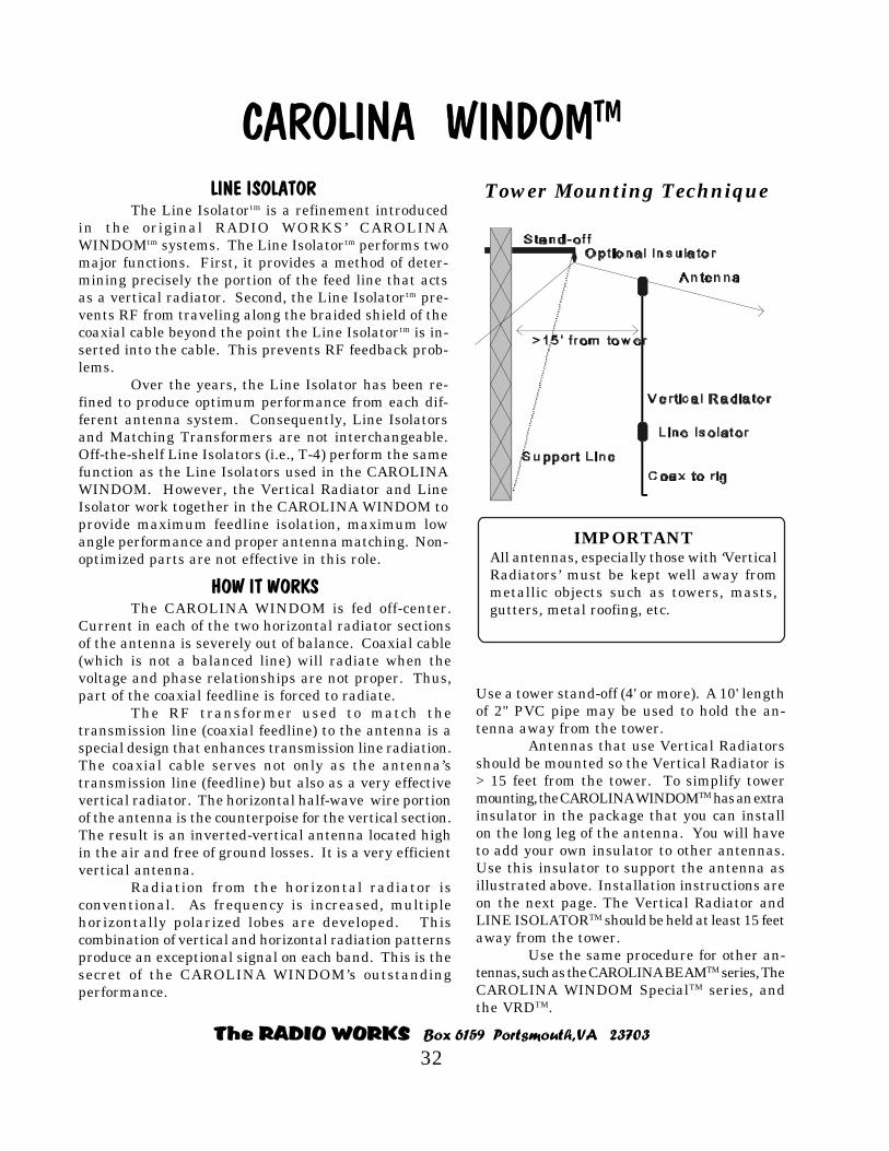
The RADIO WORKS Box 6159 Portsmouth, VA 23703
32
CAROLINA WINDOMTM
Tower Mounting Technique
HOW IT WORKSThe CAROLINA WINDOM is fed off-center.
Current in each of the two horizontal radiator sectionsof the antenna is severely out of balance. Coaxial cable(which is not a balanced line) will radiate when thevoltage and phase relationships are not proper. Thus,part of the coaxial feedline is forced to radiate.
The RF transformer used to match thetransmission line (coaxial feedline) to the antenna is aspecial design that enhances transmission line radiation.The coaxial cable serves not only as the antenna’stransmission line (feedline) but also as a very effectivevertical radiator. The horizontal half-wave wire portionof the antenna is the counterpoise for the vertical section.The result is an inverted-vertical antenna located highin the air and free of ground losses. It is a very efficientvertical antenna.
Radiation from the horizontal radiator isconventional. As frequency is increased, multiplehorizontally polarized lobes are developed. Thiscombination of vertical and horizontal radiation patternsproduce an exceptional signal on each band. This is thesecret of the CAROLINA WINDOM’s outstandingperformance.
LINE ISOLATORThe Line Isolatortm is a refinement introduced
in the original RADIO WORKS’ CAROLINAWINDOMtm systems. The Line Isolatortm performs twomajor functions. First, it provides a method of deter-mining precisely the portion of the feed line that actsas a vertical radiator. Second, the Line Isolatortm pre-vents RF from traveling along the braided shield of thecoaxial cable beyond the point the Line Isolatortm is in-serted into the cable. This prevents RF feedback prob-lems.
Over the years, the Line Isolator has been re-fined to produce optimum performance from each dif-ferent antenna system. Consequently, Line Isolatorsand Matching Transformers are not interchangeable.Off-the-shelf Line Isolators (i.e., T-4) perform the samefunction as the Line Isolators used in the CAROLINAWINDOM. However, the Vertical Radiator and LineIsolator work together in the CAROLINA WINDOM toprovide maximum feedline isolation, maximum lowangle performance and proper antenna matching. Non-optimized parts are not effective in this role.
Use a tower stand-off (4' or more). A 10' lengthof 2" PVC pipe may be used to hold the an-tenna away from the tower.
Antennas that use Vertical Radiatorsshould be mounted so the Vertical Radiator is> 15 feet from the tower. To simplify towermounting, the CAROLINA WINDOMTM has an extrainsulator in the package that you can installon the long leg of the antenna. You will haveto add your own insulator to other antennas.Use this insulator to support the antenna asillustrated above. Installation instructions areon the next page. The Vertical Radiator andLINE ISOLATORTM should be held at least 15 feetaway from the tower.
Use the same procedure for other an-tennas, such as the CAROLINA BEAMTM series, TheCAROLINA WINDOM SpecialTM series, andthe VRDTM.
IMPORTANTAll antennas, especially those with ‘VerticalRadiators’ must be kept well away frommetallic objects such as towers, masts,gutters, metal roofing, etc.

The RADIO WORKS Box 6159 Portsmouth, VA 23703
33
Installing the Optional Strain InsulatorsSome antennas are supplied with one or more extra insulators for use in reconfiguring antennas.For example, an extra insulator is included with CAROLINA WINDOMS of all types to aid intower or mast mounting. The BigSig Loop and Super Loop have two extra insulators forreconfiguring loops from triangular configurations to rectangular configurations. However, inthe case of loop antennas, it is recommended that you install them as delta-loops, if possible.
The extra insulators must be installed by the user, but they are made to be slipped over the wireand twisted into place. You do not have to thread the antenna wire through an “eye” on a stan-dard insulator, so these insulators are simple to install.
Step 1At the proper point along the antenna wire,press the antenna wire through the clipson the side of the insulator. Bend the wirearound the insulator and press the wirethrough the clip on the opposite side of theinsulator.
Step 2Tightly twist the wire together for severalturns. Soldering is not necessary. The wirewill not untwist if the twists are tight.
Step 3Thread several inches of support ropethrough the insulator as shown above.
Step 4Tie the support rope with a reliable knot. ABowline is shown in the installation sectionof this manual. Shown above are two half-hitches.

The RADIO WORKS Box 6159 Portsmouth, VA 23703
34
10' Vertical Radiator18' on “40 Plus” version
50 Ohm Line Isolator
Matching Unit
25'
5 0 O h m C oax t o T un e r
41'
10' Vertical Radiator
50 Ohm Line Isolator
Matching Unit
13'
5 0 O h m C oa x t o T un e r
21'
CAROLINA WINDOM 40, 40 Performance Plus,
CAROLINA WINDOM 20 & 620
Follow the installation procedures outlined
starting on page 20.
Configuration vs. Length needed
Flat top: 70'Inverted-V @ 40' height:100' minimumInverted-V @ 60' height:120' minimumInverted-U @ >30' height: length = 41'Inverted-U Bend = 5' short leg; 10' long legSloper @ 40' = 58'Sloper @ 60' = 40'It’s OK to bend the ends of the antenna.
Recommended mounting configuration:
Flat-top, suspended between two tall trees located >70' apart.
IMPORTANTThe vertical section MUST be kept well awayfrom metallic objects, such as towers, masts,gutters, metal roofing, etc.
See Tower mounting technique - page 32.
GENERAL MOUNTING REQUIREMENTS
*Mounting height of vertical section: >25'*Minimum recommended angle between legs = 126°*Minimum height at ends = 8'
GROUND SPACE REQUIRED
This antenna is only 34 feet long. You can support yourCAROLINA WINDOM 20 or 620 as a flattop, sloper, orinverted-V.
Recommended configuration:Flattop, suspended between two tall trees or similar supportslocated >40' apart.
Special considerations for 6 meter operation.
You will want the best performance possible from yourCAROLINA WINDOM 620 when you are operating on 6meters. Two issues must be considered.
1. Antenna location and configuration2. Feed line
For maximum 6 meter performance, supporting this antennaas a flattop is best. Bending the antenna into an inverted-Vwill reduce 6 meter performance. With the short length ofthis antenna, this should not be a problem.
Feed lines - Since 6 meters is in the VHF spectrum, morecare must be taken when choosing coaxial cable for theantenna’s feed line. Unless the length of feed line is short,less than 75 feet, you should use RG-213 or better coax. Forshorter lengths than 75 feet, quality RG-8X will be fine.
You will be using a tuner with this antenna on 6meters, so you want feed line with the minimum loss possible.However, unless you need to run a very long coax run, thereis no real need to use expensive, low-loss coax types.
SAFETY FIRST - Read the Caution Page in this manual before proceeding with installation.
GENERAL MOUNTING REQUIREMENTS
*Mounting height of vertical section: >25'*”40 Plus” version requires > 33'*Minimum recommended angle between legs = 126° .*Minimum angle between legs = 90O
*Minimum height at ends = 8'
CAROLINA
WINODOM 40
& 40 Plus
CAROLINA
WINODOM 20 & 620

The RADIO WORKS Box 6159 Portsmouth, VA 23703
35
CAROLINA WINDOM 160TM
22' Vertical Radiator
50 Ohm Line Isolator
Matching Unit
83'
50 O h m C oa x (R G -8 X ) toyou r Tu ner
182'
CAROLINAWINDOM
160
Follow the installation procedures outlined
starting on page 20.
SPECIFICATIONS
Freq. coverage: 160 - 10 metersGain: As much as 10 dBd* reportedRadiator length: Horizontal 265' Vertical 22'Polarization: Both vertical and horizontalMatching method: TunerTuner needed: YesPower Rating: 1500 Watts CW/SSB See page 5.Recommended Hgt.: >40'- Usable at 35'Radials? Not required* Based on user reports, field evaluations, and productreviews.
IMPORTANTVertical section MUST be kept well away frommetallic objects, such as towers, masts, gutters, metalroofing, etc.
See Tower mounting technique detailed earlier inthis manual.
Watch your wattmeter closely. If any ofthe antenna’s components are beingover stressed, you will see an upwarddrift in reflected power. Reduce trans-mitter power until there is no drift inmeter readings.
Read the information on theCAROLINA WINDOM 80.
Support ConfigurationsGENERAL MOUNTING REQUIREMENTS
GROUND SPACENEEDED
Mount your 160 meterCAROLINA WINDOM tm
using good HF antennainstallation technique. Dueto the very large size of thisantenna, you may want tobend the ends of the antennavertically or horizontally ifthe full 270' of mountingspace is not available. Thiswill not usually reduce theperformance of theCAROLINA WINDOMtm onthe lower bands. There maybe some effect on theradiation pattern on thehigher bands.
Of course, it is best, if you have the room, to putthe antenna in the air as a flattop or inverted-V. SWRis only one indicator of an antenna’s performance. Reactance,band to band, is well controlled and the SWR, though not below2:1, is low enough to avoid high losses in the coaxial feed line.Your tuner easily matches the antenna feed system to yourrig.
You have all the convenience of an open-wire fedantenna, with the convenience of coaxial cable.
As the CAROLINA WINDOM 160tm comes to you, itis adjusted for maximum radiation performance on all bands.
Operating on other frequencies
Operating a CAROLINA WINDOMtm outside the amateurradio bands is possible. Transmitter power will usuallyhave to be reduced to a few hundred watts. Do not useyour linear. You will need a wide range, manual tuner.
SAFETY FIRST - Read the Caution Page in thismanual before proceeding with installation.
*Mounting height of vertical section: >40'*Minimu mangle between legs = 126 degrees*Minimum height at ends = 8'

The RADIO WORKS Box 6159 Portsmouth, VA 23703
36
CAROLINA WINDOM Low Profile “LP” Versions
CAROLINA WINDOM 80 LP CAROLINA WINDOM 40 LP
CAROLINA WINDOM 40 Performance PLUS LP
CAROLINA WINDOM Short 80 LP CAROLINA WINDOM Short 80 LP
CAROLINA WINDOM 20LP CAROLINA WINDOM 620 LP
CAROLINA WINDOM Low Profile “LP” VersionsCAROLINA WINDOM Low Profile “LP” Versions
CAROLINA WINDOM 80 LP CAROLINA WINDOM 40 LP
CAROLINA WINDOM 40 Performance PLUS LP
CAROLINA WINDOM Short 80 LP CAROLINA WINDOM Short 80 LP
CAROLINA WINDOM 20LP CAROLINA WINDOM 620 LP
CAROLINA WINDOM Low Profile “LP” VersionsIMPORTANTIMPORTANT
Follow the installationprocedures outlined
starting on page 20.
Follow the installationprocedures outlined
starting on page 20.
InstallationFollow all of the installation instructionsfor the standard CAROLINA WINDOM ver-sions.
The “LP” versions of the CAROLINAWINDOM antennas are identical to thestandard size versions with the exceptionof the matching transformer, Line Isolator,and power limits. The “LP” is a full perfor-mance CAROLINA WINDOM.
Antenna Support HeightSince these are easier to hide, stealthy an-tennas, they have been optimized for lowersupport heights. Standard CAROLINAWINDOMS are optimized for a supportheight of 50 feet, whereas the LP versionsare optimized for a height between 30 and40 feet.
Though optimized for a height of between30 and 40 feet, performance will be im-proved if the antenna is supported higheroff the ground. There is nothing wrong withsupporting a CAROLINA WINDOM LP at60, 80 or even 100 feet off the ground. Onlythe SWR at the transmitter end of yourfeedline will increase while the radiationpattern and thus antenna performance willbe improved. Never substitute height for alower SWR.
Power LimitsThe power limit for all “LP” versions of the
CAROLINA WINDOM is 600 watts CW/SSBoutput under normal duty-cycles. That duty-cycleis 25%. In other words, no more than 25%transmitting time followed by 75% listening time.Maximum key down time is 30 seconds.
Watch your reflected power meter when usingthe antenna. If the reflected power drifts upwardor downward, as you transmit, the componentsinside the matching transformer or Line Isolatorare overheating. There are many things whichcan cause this. Most often it is excessive power,spurious output or parasitic oscillation from yourlinear amplifier, or a combination of all three.Sometimes, the reflected power will change as anantenna “swings” in the breeze. This is normal.
The 600 watt power rating of the “LP” seriesof CAROLINA WINDOMS means that it shouldbe able to handle the output power of many solidstate linears and 811-class amplifiers like theAmeritron AL-811 or Collins 30L-1. TheAmeritron AL-811H and some single tube 3-500amps may be used with the “LP” series ofantennas but you will have to keep the powerdown and don’t overdo your speech processing. Ifyou need to run more power, you need thatstandard version of the CAROLINA WINDOM.
Operating ModesCW and SSB are the design modes. PSK-31should be OK if you run your rig at 100 watts orless. AM, FM, RTTY and other high duty-cyclemodes are not recommended, and will probablyresult in antenna component failure.
The RADIO WORKS Box 6159 Portsmouth, VA 23703
37
CAROLINA WINDOM Short 80TM
GENERAL MOUNTING REQUIREMENTS
*Mounting height of vertical section: >35'(30' if two 16' verticals are used)
*Recommended configuration: Flat-top*Inverted-V configuration is usable if the angle is large.Note: Inverted-V configuration upsets element spacing and altersthe pattern.*Minimum height at vertical ends: >8'
Recommended mounting configuration Flat-top, suspended between two tall trees located >100' apart.
LINE ISOLATOR
The ‘Line Isolator’ is a refinement introduced in theoriginal RADIO WORK’S CAROLINA WINDOM systems.The line isolator performs two major functions. First, itdetermines precisely the portion of the feed line that actsas a vertical radiator. Secondly, the Line Isolator preventsRF from traveling along the outside of the braided coax’sshield beyond the point where the Line Isolator is inserted.This is important in preventing RF feedback problems.
Can I Turn My CAROLINA WINDOM
into a CAROLINA Short?
Each DMU (Dedicated Matching Unit) in theCAROLINA WINDOM and CAROLINA Short isoptimized for a specific antenna system. A DMU mustprovide the correct current imbalance and outputimpedance to produce maximum efficiency from aparticular antenna.
Similarly, the new CAROLINA Short’s‘DEDICATED MATCHING UNIT’ provides the loadreactance and proper phase response necessary forproper operation of the CAROLINA Short’s ‘VerticalRadiator Element.’
Unfortunately, the DMUs cannot beinterchanged. Just bending up a CAROLINA WINDOMmeans you would give up much of the performancecapability of the CAROLINA Short.
HOW IT WORKS
The CAROLINA WINDOM Short80tm or CAROLINA WINDOM Short 40tm
antenna system combines the bestcharacteristics of the CAROLINAWINDOM and the ‘Bobtail Curtain.’ Themain reason for the CAROLINAWINDOM’s exceptional performance is its‘Vertical Radiator Section.’ The CAROLINAWINDOM Short is similar to the CAROLINAWINDOM in that it is fed off-center. Thisforces the current in each half of thehorizontal radiator sections of the antennato be severely out of balance. Coaxial cable(which is not a balanced line) will radiatewhen the voltage and phase relationshipsare not properly balanced.
The RF transformer used to matchthe transmission line (coaxial feedline) tothe antenna is a special design thatenhances transmission line radiation.Thus, the coaxial cable serves not only asthe antenna’s transmission line (feedline)but it functions, simultaneously, as aneffective vertical radiator. The horizontalwire portion of the antenna interconnectsthe three vertical sections. The result is amulti-element inverted-vertical antennahigh in the air and free of major groundlosses. Radiation from the horizontalsection of the antenna is conventional.
The CAROLINA WINDOM Short 80tm
was previously know as the CAROLINABEAM 80tm. Likewise the CAROLINAWINDOM Short 40tm was previouslyknow as the CAROLINA BEAM 40tm.
SAFETY FIRST - Read the Caution Page in this manual before proceeding with installation.

The RADIO WORKS Box 6159 Portsmouth, VA 23703
38
42'
50'
8' 10' 16' 8'
#2 Vertical Radiator
8'25'Matching Transformer
#1 VerticalRadiator
17'
Line Isolator
50-ohm coax, user supplied
#3 VerticalRadiator
Use eitherVertical RadiatorCAROLINA WINDOM Short 40
84'
100'
16' 22' 32' 16'
#2 Vertical Radiator
16'50'Matching Transformer
#1 VerticalRadiator
34'
Line Isolator
50-ohm coax, user supplied
#3 VerticalRadiator
Use eitherVertical Radiator
CAROLINA WINDOM Short 40TM and Short 80TM
Freq. coverage: 40 - 10 metersRadiator length: Horizontal 42' or 50'
Verticals 8',10',8' or 8',10',16'Polarization: Vertical and horizontalFeed line: 50 ohm Coaxial cableMatching method: TunerTuner needed: Yes, on all bands.Power Rating: 1500 Watts CW/SSB See page 5Recommended Hgt. >35'- Usable at 30'
All CAROLINA WINDOM Short 40tm elements areinteractive and must be in alignment for proper op-eration of the antenna. SWR is only one factor thataffects an antenna’s performance. Reactance, bandto band, is well controlled and the SWR, though notbelow 2:1, is low enough to avoid high losses in thecoaxial feed line. Your manual tuner easily matchesthe antenna feed system to your rig. This gives youall the convenience of an open-wire fed antenna, withthe convenience of coaxial cable.
As the CAROLINA WINDOM Short 40tm comes toyou, it is adjusted for maximum radiation performanceon all bands, 40 through 10 meters.
Follow the installation procedures
outlined starting on page 20.
SAFETY FIRST - Read the Caution Page in this manual before proceeding with installation.
Freq. coverage: 80 - 10 metersRadiator length: Horizontal 84' or 100'
Verticals 16'/22'/32' or 16'/22'/16'Polarization: Vertical and horizontalFeed line: 50 ohm Coaxial cableMatching method: TunerTuner needed: Yes, on all bands.Power Rating: 1500 Watts CW/SSB See page 5Recommended Hgt. >35'- Usable at 30'
The CAROLINA WINDOM Short 80tm is a uniquecombination of the CAROLINA WINDOMtm and the veryhigh performance wire beam, the ‘Bobtail Curtain.’
The CAROLINA WINDOM Short 80’s radiationpattern is different from simple dipoles and similarantennas. The CAROLINA WINDOM Short 80tm combinesthree vertical elements with a single horizontal radiator.It is this unique combination of horizontal and verticalradiating elements that account for the outstandingperformance of this antenna system. An added benefit ofthis system is the short length of the CAROLINAWINDOM Short 80tm. At only 84' or 100' in length, it ismuch smaller than an 80 meter dipole.
As the CAROLINA WINDOM Short 80tm comesto you, it is adjusted for maximum radiation performanceon 80 - 10 meters.
All CAROLINA WINDOM Short 80tm elementsare interactive. Reactance, band to band, is well controlledand the SWR, though not below 2:1, is low enough to avoidhigh losses in the coaxial feed line. Your manual tunereasily matches the antenna feed system to your rig. Thisgives you all the convenience of an open-wire fed antenna,with the convenience of coaxial cable.

The RADIO WORKS Box 6159 Portsmouth, VA 23703
39
#1 Vertical Radiator
Special Matching Unit
50 Ohm Coax, user supplied
#3 Vertical Radiator#2 Vertical RadiatorLine Isolator
#1
#2 #3 #4
#5
#1 Vertical Radiator
Special Matching Unit
50 Ohm Coax, user supplied
#3 Vertical Radiator#2 Vertical RadiatorLine Isolator
Use inner Insulator to Increase Lengthof Vertical Radiator
#1
#2 #3
#4
#5
#1 V ertical Radiator
Spe cial Matching Un it
50 Ohm Coax, user supplied
Lin e Isolator
Use Outermost End Insulator Use Outermost End Insulator
#1 #2 #3 #5#4
Field ReconfigurableThe pattern of the CAROLINA Shorttm is adjustable. The insulators are installed at the proper points toallow any of three configurations. Typically, the pattern of a CAROLINA Shorttm has multiple, largemajor lobes, with deep nulls between. The angle of radiation is very low and favors long-haul DX. Youmay want to experiment with the three different CAROLINA Shorttm configurations and the resultingpattern changes. It is easy to change configurations - simply insert your support rope into the appropri-ate insulator, and the job is done.
Standard ConfigurationThis configuration will give the best overall
patterns on the higher bands. The shorter Verticalradiators are optimized for the two highestfrequency bands. The spacing between theelements will produce a multi-lobe pattern on allbut the lowest band. There will be significantradiation off the ends of the antenna.
Use insulators #2 and #4 to support theantenna. You may want to hang weights or uselight weight support lines at insulators #1 and #5to keep the Vertical Radiators in place.
Alternate Configurations
Short Flat-TopThe #3 Vertical Radiator is doubled in length. Thisgenerally improves the radiation pattern on thenext to the lowest frequency band. The antenna isnow shorter which can be an added benefit to someusers. The radiation pattern of this configurationwill have multiple lobes and very deep nulls. Thetakeoff angle is very low and favors long-haul DX.
To set up your CAROLINA Short in thisconfiguration, simply use insulators #2 and #3 tosupport the antenna. Again, you may want tohang weights or use light weight support lines atinsulators #1 and #5 to keep the Vertical Radiatorsin place.
CAROLINA WINDOMYou have the option to turn your CAROLINA
Shorttm into an antenna similar to a CAROLINAWINDOM. This would be the choice if you findthe pattern of the CAROLINA Shorttm to be tooaggressive for your needs. You may want to useone configuration for contests and another foreveryday use. Try the various configurations andsee which work best for you.
The pattern will contain multiple lobes on thehigher bands, but the nulls between lobes will notbe as severe. Radiation off the ends of the antennawill be low-angle and vertically polarized. To putthe CAROLINA Shorttm into the CAROLINAWINDOM mode, use insulators #1 and #5 tosupport the antenna.
CAROLINA Short
Short Flat-top Configuration
CAROLINA WINDOM Configuration

The RADIO WORKS Box 6159 Portsmouth, VA 23703
40
CAROLINA WINDOM Special VersionsCAROLINA WINDOM 160 Specialtm CAROLINA Short 160 Specialtm
CAROLINA WINDOM 80 Specialtm CAROLINA Short 80 Specialtm
CAROLINA WINDOM Special VersionsCAROLINA WINDOM 160 Specialtm CAROLINA Short 160 Specialtm
CAROLINA WINDOM 80 Specialtm CAROLINA Short 80 Specialtm
It is possible to make a CAROLINA WINDOMwork on 160 meters. The feed point impedanceis very low, so the Matching Transformer andLine Isolator are very heavily stressed. Spe-cial Matching Transformers and Line Isolatorsare required to handle the high RF current ap-plied when operating the half-frequency band.The SWR will be high, but fortunately, on 160and 80 meters, quality coaxial cable has prac-tically no loss, so an elevated SWR does notproduce excessive loss in the feed line.
There are unavoidable losses in the LineIsolatortm and Matching Unit due to the veryhigh RF Current being fed to the antenna. Wecould optimize the Matching Unit and Line Iso-lator for the low feed point impedance, but ifwe did, we introduce unacceptably high losseson all the higher frequency bands. Conse-quently, the compromises are made on 160meters (or 80 meters in the case of the CW 80Special and CW Beam 80 Special).
You Must Reduce Power on theLowest Frequency Band.
Special heavy-duty matching transformersand Line Isolators are used in all the “Special”
antennas, but it isnot practical tobuild these parts tohandle full legalpower. Theywould be too largeand too heavy.T h e r e f o r e ,
transmitter power must be limited to 500watts or less on SSB and CW with normalduty-cycles. When using higher duty-cyclemodes, power must be reduced further.
installation where further reduction in power may berequired. Remember, adding the extra band at the lowfrequency end of the antenna’s normal operating rangeis done only to permit casual operation on that bandwhile retaining full performance on all the higherbands.
Where does the signal go?
Component losses, combined with the very shortradiator length on 160 meters results in a loss of overallsystem efficiency on that band. Compared with full-sized 160 meter antennas, you can expect your signal
to be down between oneand two S-units.However, in situationswhere a 160 meterantenna is not practical,you will be able tooperate with a capablesignal. It’s an excellent
compromise and permits experiencing one of the lowerfrequency bands when space doesn’t permit largerantennas.
Because there is a significant amount of powerdissipated in the matching transformer and LineIsolator, you must lower power to a maximum of 500watts on the lowest frequency band. Failing to do sowill cause overheating of the matching transformer andLine Isolator and their ultimate failure.
On the higher bands, 80 - 10 meters, where the antennais now operating in its normal design mode, losses areminimal and the antenna takes on its usual exceptionalcharacteristics. Performance is not compromised onthese bands, and full power may be used.
There are unavoidable losses
Transmitter power must belimited to 500 watts orless on SSB and CW withnormal duty-cycles.
Operation on 160 metersresults in a loss in overallsystem efficiency, but not onthe higher bands.

The RADIO WORKS Box 6159 Portsmouth, VA 23703
41
CAROLINA WINDOM 80 & 160 SPECIALTM
Follow the installation procedures
outlined starting on page 20.
22' Vertical Radiator
50 Ohm Line Isolator
Matching Unit
50'
50 Ohm Coax toTuner
83'
CAROLINA WINDOM 160 Special
Most automatic tuners do not have tuning rangeto match this antenna on 160. In that case, awide range manual tuner is required. Unsatis-factory tuning with manual tuners can usuallybe traced to improper station grounding orground loops.
SpecificationsFreq. coverage: 160 - 10 metersFeed line: 50 ohm coaxial cableTuner needed: Yes, all bandsPower Rating: 1500 Watts (40 - 10 m)*
500 w MAX (160 m)*Recommended Hgt.: >35'- Usable at 30'
*CW/SSB duty-cycles only.
Watch your wattmeter closely. If any of theantenna’s components are being over stressed,you will see an upward drift in reflected power.Reduce transmitter power until there is no driftin meter readings.
SAFETY FIRST - Read the Caution Page in this manual before proceeding with installation.
CAROLINA WINDOM 80 Special
10' Vertical Radiator
50 Ohm Line Isolator
Matching Unit
25' 41'
50 Ohm Coax to Tuner
SpecificationsFreq. coverage: 80 - 10 metersFeed line: 50 ohm coaxial cableTuner needed: Yes, all bandsPower Rating: 1500 Watts (40 - 10 m)*
500 w MAX (80 m)*Recommended Hgt.: >30'- Usable at 25'
*CW/SSB duty-cycles only.
In both antennas, all elements are interac-tive and must be in alignment for proper operationof the CAROLINA WINDOM Special. Reactance,band to band, is well controlled and the SWR,though not below 2:1, is low enough to avoid highlosses in the coaxial feed line. Your wide rangemanual tuner easily matches the antenna feed sys-tem to your rig.
If you use an automatic antenna tuner on40 - 10 meters, and the CAROLINA WINDOM’sSWR is beyond the tuning range of your automatictuner, trimming the length of coax feedline willusually produce acceptable results.
Try adding a short jumper in series withthe feed line at the transmitter. 6' to 12' is a goodstarting length. Since all installations are differ-ent, you may want to experiment to achieve the bestresults. You have all the utility of an open-wire fedantenna, with the convenience coaxial cable. Auto-matic tuners generally do not have sufficient tun-ing range for the lowest frequency band covered.

The RADIO WORKS Box 6159 Portsmouth, VA 23703
42
CAROLINA WINDOM Short 160 Special & Short 80 Special
#1 Vertical Radiator
Special Matching Transformer
50 Ohm Coax, user supplied
Optional #3 Vertical#3 Vertical Radiator#2 Vertical Radiator
Line Isolator
22'
16'16'
32'
34' 50' 16'
100'84'
CAROLINA WINDOM Short 160 Special
#1 Vertical Radiator
Spe cial Matching Transformer
50 Ohm Coax, use r supplied
Op tional #3 Vertical#3 Vertical Radiator#2 Vertical Radiator
Line Isolator
10'
8'8'
16'
17' 25' 8'
50'42'
CAROLINA WINDOM Short 80 Special
Follow the installation proceduresoutlined starting on page 20.
All CAROLINA WINDOM Short Specialtm
antenna elements are interactive and must bein alignment for proper operation of theantenna. Reactance, band to band, is well con-trolled and the SWR, though not below 2:1, islow enough to avoid high losses in the coaxialfeed line. Your tuner easily matches theantenna feed system to your rig. This gives youall the convenience of an open-wire fed antennawith the convenience coaxial cable.
Can I Turn My CAROLINA WINDOM
into a CAROLINA WINDOM Short?
Each DMU (Dedicated MatchingUnit) in the CAROLINA WINDOM andCAROLINA Short is optimized for a specificantenna system. A DMU must provide thecorrect current balance and outputimpedance to produce maximum efficiencyfrom a particular antenna.
Similarly, the new CAROLINAShort’s ‘DEDICATED MATCHING UNIT’provides the load reactance and properphase response necessary for properoperation of the CAROLINA BEAM’s‘Vertical Radiator Element.’
Unfortunately, the DMUs cannot beinterchanged. Just bending up aCAROLINA WINDOM means you wouldgive up much of the performancecapability of the CAROLINA Short.
The CAROLINA WINDOM ShortThe ‘CAROLINA WINDOM Short 160 SPECIALTM’ andthe ‘CAROLINA WINDOM Short 80 SPECIALTM’ are aunique combination of the CAROLINA WINDOMTM andthe very high performance wire beam, the ‘BobtailCurtain.’
The CAROLINA WINDOM Short SPECIAL’sTM
radiation pattern is different from simple dipoles andsimilar antennas. The CAROLINA Short SPECIALTM
combines three vertical elements with a singlehorizontal radiator. It is this unique combination ofhorizontal and vertical radiating elements that accountfor the outstanding performance of this antenna system.
An added benefit of this system is the reducedlength of the CAROLINA WINDOM Short SPECIAL.TM
CAROLINA WINDOM Short 160 SpecialWhen operating the CAROLINA WINDOM
Short version on its lowest design frequency, thefeedpoint impedance is very low. This results in a highSWR. Feed line losses are low on 80 and160 m, so lossdue to the SWR are low. However, very high RF currentpasses through the DMU and the Line Isolator. Thehigh current requires that you keep the transmitteroutput below 500 watts (CW and SSB duty cycles).
SAFETY FIRST - Read the Caution Page in this manual before proceeding with installation.

The RADIO WORKS Box 6159 Portsmouth, VA 23703
43
CAROLINA WINDOM Shortwave
SPECIFICATIONS
Freq. coverage: HF SpectrumRadiator length: Horizontal 66'
Vertical 12'Polarization: Both vertical and
horizontal componentsFeed line: 50 ohm coaxial cable,
RG-8X recommended.Matching method: Dedicated Matching UnitRecommended Height: >30'- Usable at 20'Radials? Not required* Based on user reports, field evaluations, and product reviews.
12' Vertical Radiator
50 Ohm Line Isolator
Matching Unit
25'
50 O h m C oa x toR e ce ive r
41'
General Mounting Requirements
*Mounting height of the antenna: >20'*Minimum recommended angle between legs = 126° .*Minimum angle between legs = 90 degrees*Minimum height at ends = 8'
Recommended mounting configurations:Flattop, suspended between two tall trees located >70'apart.
This antenna is very forgiving and can be bent tofit the available space. Bends in the wire shouldnot be less than 90-degrees (the angle between legs).Larger angles are recommended. As with allantennas, the higher the antenna is in the air, thebetter the performance.
IMPORTANTVertical section MUST be kept well away frommetallic objects, such as towers, masts, gutters,metal roofing, etc.
See Tower mounting technique - See page 32.
The CAROLINA WINDOM Shortwave is a new ap-plication of the CAROLINA WINDOM. Our new“Low Profile” matching transformer and Line Iso-lator are featured. The antenna is designed to coverthe HF spectrum, but it is usable in the BC bandand up to 50 MHz. It is optimized for frequenciesbetween 5 and 30 MHz.
A manual antenna tuner can improve performancein critical applications, but is generally not neces-sary and does not produce a worthwhile improve-ment in reception. The reception pattern is essen-tially omnidirectional which is ideal for shortwavelistening. This antenna is intended for quality re-ceivers as the excellent signal capture effect of thisantenna may overload some receivers. This is thesimple consequence of an efficient antenna thatproduces gain at most medium and higher short-wave frequencies. You may find it useful to useyour receiver’s attenuator under some circum-stances.
The CAROLINA WINDOM Shortwave provides in-creasing performance when signals are arriving atvery low angles. This effect can enhance distantstations significantly.
SAFETY FIRST - Read the Caution Page in this manual before proceeding with installation.
Follow the installation proceduresoutlined starting on page 20.

The RADIO WORKS Box 6159 Portsmouth, VA 23703
44
Troubleshooting Antennas
The CAROLINA WINDOMS
83'50'
22' Vertical Radiator Matching Unit
Line Isolator
RG-8X to tuner,user supplied
CAROLINA WINDOM 80
CHECK THE SWR
Use low power and measure the SWR at several differentfrequencies between 3.5 MHz and 3.8 MHz. A normalCAROLINA WINDOM 80 will have an SWR minimumof about 1.5:1 at 3.65 MHz. This frequency may vary100 KHz up or down depending on the antenna’senvironment. Also, the SWR may be higher or lower.On the CAROLINA WINDOM 40, the lowest SWR willbe in the middle of the 40 meter band. Similarly, othermodels will exhibit the lowest SWR on the band covered.The exceptions are the “Special” versions where thelowest SWR will be on the band next to the lowest bandcovered.
If you do not measure this drop in SWR somewhere inthe lower part of the lowest band covered, either theantenna is severely detuned by its environment or thereis a problem with the system. Vertical Radiator mustbe at least 15-feet from any metal object.
It is normal for the SWR to run between 2:1and 4:1 when your tuner is out of the circuit.
In the CAROLINA WINDOM’s history, there have beenvery few failures. First, check for open or shortedconnectors and damaged coaxial cable. The ‘DedicatedMatching Unit’ and the ‘Line Isolators’ are generallybulletproof.
Checking out the CAROLINA WINDOMAntenna with an Ohm Meter
1. Measure across the coaxial connector at thetransmitter end of the coaxial cable, the ohmmetershould indicate a very low resistance(approximately 1 ohm).
2. Disconnect the ‘Line Isolator’ from the ‘DedicatedMatching Unit’ and repeat the measurement. Thistime the measurement should indicate an opencircuit at the transmitter end of the cable. If not,check for a shorted connector or bad coax.
The only DC short in the system is in the ‘DedicatedMatching Unit’ or ‘DMU.’ All inputs and outputsof the ‘DMU’ should be a very low resistance fromany terminal to another. If there is an open circuit,the ‘DMU’ is bad.
The Coax and Line Isolator should present an opencircuit when measuring across a connector. Youwill measure a low resistance when measuring fromthe input center-pin of the Line Isolator to thecenter-pin of the connector at the end of the verticalradiator. Measure from center pin to center pinand from nut to nut. (The nut is the part of thecoaxial connector that is free to spin.) A shortcircuit can usually be traced to a bad connector.
Intermittents: If there is an intermittent problemwith your antenna, it can usually be traced to thefeedline and its connectors. Check each connectorin the system. Repeat the procedure in theparagraph above, and gently pull or twist eachconnector. Any change in a meter reading indicatesa bad connector. Also, make sure there are no signsof moisture entering the connector or coax.
Occasionally, you will put up an antenna, and itwill not work as anticipated. Most often thefault is improperly installed connectors, badcoax, an installation error or something elseeasily remedied. If your antenna does not seemto be performing properly, below are a fewsimple tests to help locate the problem.

SuperLoop 80tm & SuperLoop 40tm
Swit ching St ub
#14 St randed Ant enna Wire
HD Ladder Line
Dedicat ed Mat ching unit
50 Ohm Coax t o t ransmat chDXpedition Proven
Endorsed by Contest Ops
SuperLoops
56 '
16 '
Mechanical connection on ly
SuperLoop 40
Swit ching Stub
#14 St randed Ant enna Wire
HD Ladder Line
Dedicat ed Matching unit
50 Ohm Coax t o t ransmat chDXpedition Proven
Endorsed by Contest Ops
SuperLoops
112'
31'
Mechanical connection only
SuperLoop 80
See page 27 for installation instructions.
The SuperLoop 80tm is a remarkable antenna.It is an automatic bandswitching 80 through 10 meterloop antenna. The SuperLoop 80 reconfigures itself froma full-size, full-wave loop on 80 meters into a mutli-wave-length “Bi-square” on higher frequency bands. TheSuperLoop’stm impedances and reactances are so wellmanaged that the SuperLoop 80 may be fed on all bandswith coaxial cable. You will have to use your tuner(transmatch).
The Dedicated Matching Unit, alongwith all the other components in the antenna, workstogether to provide a relatively low SWR on allbands. The SWR is not below 2:1. However, it islow enough to allow the use of coaxial cable. Lossesare low.
One further purpose of the dedicated tuningunit is to provide the interface between theunbalanced coaxial cable and balanced loopantenna. In other words, the dedicated tuning unitfunctions as both a multiband antenna matchingdevice and a high performance balun.
INSTALLATIONYour SuperLoop 80 or 40 comes to you
assembled except two connections which must besoldered. It is complete with a custom designed“Dedicated Matching Unit.” You provide a coupleof convenient trees or other suitable structures thatare at least 120' apart and a minimum of 35 feethigh.
Erect your SuperLoop as a ‘Delta loop’ withthe apex down. If this is not possible, you may addinsulators to the loop and form it into a rectangleor square. See page 33 for insulator installationinstructions. As a last choice, you may turn theantenna upside down and feed it from the top withthe apex up. The SuperLoop is designed to besupported apex down.
Opening the SuperLoop into a rectangle orsquare may slightly improve gain and bandwidth on 80and 75 meters, but could shift resonance with 40 meterband.
SuperLoopTM HeightIf the supports available are shorter than the
minimum required height, you may tilt or slope aSuperLoop antenna. Just pull the bottom of the antennato one side, so that it does not hang vertically. Like allsloping antennas, the SuperLoop will tend to favorstations in the direction of the downward slope. You mayuse this effect to some advantage in DX operations.
The SuperLoop is an excellent antenna forshortwave listening.
HOW IT WORKSOn 80 meters your RADIO WORKS’ SuperLooptm
is a high performance, full size, full wave loop antenna.On 40 meters the SuperLooptm is a 2-wavelength antennathat is similar to a Bi-square. On this band its gain ap-proaches 4 dB. Gain will be higher due to the low take-off angle of the radiation pattern. A Bi-square loop isnot a closed loop. It is open-circuited exactly one wave-length around the loop. This is one purpose of the stubat the center of the top section of the loop. It createsopen circuit at the center of the antenna when operatingon even harmonically related bands starting with 40meters.
SAFETY FIRST - Read the CautionPage in this manual before proceedingwith installation.
The RADIO WORKS
Box 6159, Portsmouth, VA 23703
Installation of the 80 or 40 meter SuperLoops are identical.
45

The RADIO WORKS Box 6159 Portsmouth, VA 23703
46
‘L’½ ‘L’½ ‘L’
B1-5K Plus Balun
50-ohm coaxUser supplied
ULTIMA DIPOLEtm
Heavy Duty, Single Band Dipoles
Follow the installation procedures
outlined starting on page 20.
User Supplied Parts• RG-8X, RG-8, RG-213 or similar coaxial cable• 2 each PL-259 connectors for your coax• Support rope
Installing your Ultima DipoleYou have made an excellent antenna choice.
Now it’s time to put your Ultima Dipole into the air.Any of the configurations outlined earlier areappropriate.
Antennas for the higher bands may besupported vertically from one end. Supportedvertically, the antenna will radiate in all directionswith a low radiation angle. Always direct thetransmission line away from the antenna at a rightangle for as long a distance as possible (>1/4wavelength is desirable) to reduce interactionbetween the coax and the antenna.
ANTENNA LENGTH L(in feet) = 468/MHz
Frequency Length “L” Frequency Length “L” Frequency Length “L”3.5 MHz 134’ 7.2 MHz 65’ 21.2 MHz 22’3.6 130’ 10.12 46.2’ 24.93 18.75’3.7 126.5’ 14.0 33.5’ 28.0 16.7’3.8 123’ 14.2 33’ 28.5' 16.4'3.9 120’ 18.12 25.8’ 29.0 16.1’7.0 66.5’ 21.0 22.3’ 29.5 15.9’
Tuning your Ultima DipoleYour antenna comes to you cut for the CW end of the
band. On 160, 80, or 40 meters, you may want to trim theantenna for your favorite part of the band. Sometimes, theantenna may need trimming due to interaction with otherantennas or particular conditions at your antenna site.
If the lowest SWR occurs at a frequency lower thanneeded, shorten the antenna a few inches. Similarly, if theSWR is lowest at a higher frequency, lengthen the antenna.Refer to the “Tuning Chart” on page 60. This chart will giveyou a general idea of the length of wire involved in movingthe resonant frequency of the antenna a given number of KHz.
Lengthening or shortening the antenna is done atthe end insulators. To shorten the antenna, unwind the wireas it wraps around itself at the end insulator. Move theinsulator the required length toward the center of theantenna. Re-wrap the antenna wire to secure the endinsulator.
The antenna comes to you tuned to the CW portionof the band. It is unusual to have to lengthen the antenna.
Using a tunerYou may use a tuner (transmatch) with your UL-
TIMA DIPOLE. This is most often done on 160 or 80 metersto allow full band operation. Typically a dipole covers onlyabout 200 KHz (or less) of the band between 2:1 SWR pointson 80 meters. In some parts of the band, the SWR will riseto a fairly high figure (>4:1). A transmatch will provide agood match to the transmitter.
Do not use a dipole at twice its design frequency,even with a transmatch. (i.e. an 80 meter antenna will notwork well on 40 M when fed with coax) You may use anantenna at three times its design frequency. For example, a7 MHz antenna can be used on 21 MHz. You will probablyneed to use your transmatch to get an acceptable SWR.
SAFETY FIRST - Read the Caution Page in this manual before proceeding with installation.

The RADIO WORKS Box 6159 Portsmouth, VA 23703
47
BigSig LoopTM
SPECIFICATIONS
Freq. coverage: Available for all bandsRadiator length: 3/2 waveFeed Impedance: 50 ohmsMatching method: Balanced Matching UnitFeed line: 50 ohm coaxial cable (RG-8X)SWR: Low: Full coverage on
bands except 75/80 M.Power Rating: 1500 watts HF CW/SSB
300 watts on 6 meters. see pg. 5Radials: No
The BigSig LoopTM is an unusual 3/2 wave-
length loop that delivers outstanding performance.
The advantage of the BigSig LoopTM is its large
capture area, its low radiation angle and ease of installa-
tion. The enhanced, low angle, radiation pattern ofthe BigSig LoopTM antenna gives you the competi-tive edge over other stations using dipoles, inverted-V’s, or trap antennas, operating under similarconditions.
A balanced dedicated matching unit was custom
designed to match the BigSig loop antenna’s high
impedance to your 50 ohm coaxial cable. BigSig Loops
are easy to get up and get going.
After deciding the shape of the loop based on the spaceand supports you have available, you will need to choosethe feed point location. I generally feed all my loops atthe bottom. I find this convenient. For enhanced DXperformance, it may be desirable to have the feed pointat one corner of the loop. (Corner feeding a rectangularloop yields a vertically polarized pattern and a lower ra-diation angle). A DELTA configuration results in a com-bination of vertical and horizontal polarization.
If possible, mount your BigSig Looptm as a square orapex down Delta. This puts most of the antenna as highin the air as possible. Turning the apex of a delta up-ward will work, but a large portion of the antenna wirewill be parallel to the earth. This reduces the effectiveaverage height of the antenna.
Sloping LoopsYou may tilt a loop antenna. This can be helpful if youdo not have enough support height. Just pull the bottomaway so that the antenna is no longer vertical. Like allsloper antennas, the loop will tend to favor stations inthe direction of the downward slope. You may use thiseffect to some advantage in DX operations. You caneasily reverse the direction from the ground.
AssemblyAssembly of the BigSig Looptm is similar to theSuperLooptm. Refer to the SuperLoop’s assemblyinstructions.
INSTALLATION
You may build your BigSig Looptm as a square, triangle, rectangle, or other geometric figure. Some shapes aremarginally better than the others. The best is a circle, followed closely by a square, a rectangle, and a triangle.The larger the internal area of the loop, the higher the theoretical performance in terms of gain and bandwidth.The difference in actual performance is probably not worth the debate. Your antenna site will usually dictate theloop’s final shape. Use the instructions for the SuperLoop on page 27 omitting the installation of the ladder linestub.
The Larger the Internal Area of a Loop, the Better the Performance.
SAFETY FIRST - Read the Caution Page in this manual before proceeding with installation.

The RADIO WORKS Box 6159 Portsmouth, VA 23703
48
B
AA
B
B
C CH
DMU DMU
BigSig Configurations and Dimensions
Band Rectangular Loop Apex Down Loop
Radiator Height = A Side B Height = H Side B Side C
Length Top Length
80 420’ 50’ 160’ 65’ 190’ 115’
40 210’ 40’ 65’ 40’ 90’ 60’
30 150’ 37.5’ 37.5’ 38.7’ 55’ 47.5’
20 105’ 26’ 27’ 30’ 35’ 35’
17 84’ 21’ 21’ 24.25’ 28’ 28’
15 72’ 18’ 18’ 20.75’ 24’ 24’
12 60’ 15’ 15’ 17.3’ 20’ 20’
10 54’ 13.5 ’ 13.5’ 15.6’ 18’ 18’
Antennas are precut to the appropriate dimensions for the band of operation.
6 metersDue to small size on 6 meters its installation is flexible. It is only 13' 6" across the top as it comes from the factory.It may be reconfigured as a rectangle or square. For best performance keep the area inside the loop as large aspossible.
- TUNING -You may need to lengthen or shorten the wire elements depending on your antenna’s location and itsinteraction with other antennas. Changing the shape of the antenna may also require slight trimming.Do not cut the wire when trimming the antenna, simply use more or less wire at the insulators. Thisway, you can always change your mind if you find you have made the antenna too short when it reallyshould have been lengthened.

The RADIO WORKS Box 6159 Portsmouth, VA 23703
49
G5RV PLUSTM
only by The RADIO WORKS
51' 51'
30' 8" 450 Ladder Line
Y1-5K Plus Balun
50 ohm coax to tuner
Glass-filled Insulators
#14 Antenna Wire
SpecificationsFrequency Coverage: 80 - 10 mRadiator Length: 102’Matching Method: StubLine Isolator: Y1-5K BalunTransmatch: RequiredPower Rating: > 1500 watts, see page 5Radials: NoRecommended height: > 40’
System SWRThe SWR of the G5RV is lowest in the middle ofthe 20 meter band. Here the SWR is typically 1.8:1.On other bands, the SWR can be considerablyhigher. An SWR of 4:1 is not unusual. This isnormal and is due to the reactive nature of the feedsystem. Transmission line losses are low, so systemefficiency is high.
Effects of Nearby ObjectsAs with all antennas, mount your G5RV PLUS ashigh and in the clear as possible. The ladder linestub is critical to the proper operation of theantenna. The ladder line stub MUST be kept awayfrom anything that could affect its characteristics.This includes any non-insulating material and theground. The stub should be routed perpendicularlyaway from the radiator. The coaxial cable may behandled in any convenient manner.
Automatic TunersManual or external automatic tuners are best, butthe G5RV PLUS is compatible with many built-in“automatic” tuners. Tuning range may be limitedon part of 80/75 meters.
CAVEATOne short caveat. On some frequencies, the G5RVPLUS may be too reactive for the limited tuningrange of automatic tuners built into some rigs. Anexternal automatic tuner or a manual tuner canmatch a variety of loads and are perfectly suitablefor use with the G5RV PLUS.
System GroundIt is necessary to provide a good ground sys-tem for your station’s equipment. This is donefor a variety of reasons. As a minimum, groundyour equipment by driving a long “ground rod”into earth. See the section on grounding. Con-nect the ground rod to your rig with a short,heavy gauge copper wire, braid, or strap.
Installing Your New G5RV PLUSThere are many ways to install your G5RVPLUS antenna. Read information beginningon page 20 for installation tips. It is importantto keep the ladder line matching sectionof the G5RV away from anything metal.It must not come in contact with theground. The ladder line stub may be directedaway from the antenna at an angle if supportheight is less than 32 feet.
The G5RV PLUS was designed to be supportedin the flattop configuration. Bending or slop-ing the antenna will affect the G5RV’s match-ing system. This doesn’t mean that your G5RVPLUS won’t work. It will just tune up differ-ently.
To hang the G5RV PLUS from its center, sim-ply wrap your support line between a pair ofthe ribs in the center insulator.

The RADIO WORKS Box 6159 Portsmouth, VA 23703
50
Check the Specstm
The RADIO WORKS Is .... B A L U N S
The RADIO WORKS introduced a fullline of precision, Current-typeTM baluns in1986. We were actually producing Current-typeTM baluns in 1984, but it was not until 1986that they became generally available to thepublic. They were instantly popular becauseCurrent-typeTM baluns avoid the problemsconventional ‘Voltage-type’ baluns exhibit.
Since low impedance antennas arecurrent-fed, a balun that produces equal andopposite current at its output over a wide rangeof load impedances is desirable. ‘Voltage-type’baluns produce equal and opposite voltages atthe balun’s balanced port. There is little to begained by forcing the voltages of the twoantenna halves, whether the antenna isbalanced or not, to be equal and opposite inphase. The antenna field is proportional to thecurrents in the elements, not the voltages atthe feed point.
Current-typeTM baluns are not a newidea. They have been used in TV receivers formany, many years. TV tuners require a verywide bandwidth balun that will work with aseverely mismatched antenna, like a TV’s so-called ‘rabbit ears’ antenna. The Current-typeTM balun was the best choice for thatapplication.
Unfortunately, when baluns were firstpopularized for use with antennas, a voltage-type design was chosen. Other balun makersjust followed along. It was years before thefirst true, Current-type baluns appeared on themarket.
Of course, times change and today youcan find entire books devoted to Current-typeTM
baluns. The Radio Works was the first to offeryou a full line of Current-type baluns for everyapplication.
(This text was taken from the RADIO WORKS’ ReferenceCatalog, copyright 1992, page 11.)
Misconceptions
1. Baluns will not improve SWR (the exception iswhere a balun is used as part of a matchingnetwork, i.e., 4:1 baluns used in loops)
2. They are not lightning arresters. The windinginductance in most baluns is far too low.
3. Built-in spark-gaps do not work. The radioequipment is destroyed long before the ‘spark gap’arcs over.
4. Baluns do not allow multiband operation of singleband, coax fed, antennas. They do not makeantennas more broadbanded.
These are all generalizations and, of course, there maybe specific exceptions to any of them.
A balun really has only two jobs
1. Isolate transmission line from the antenna.2. Provide balanced output, either voltage or current.
Proper Balun DesignA properly engineered balun will include these designpoints:
1. High winding inductance (high reactance)2. Low stray capacitance3. Very short internal transmission lines -
<< 1/4 wave, the shorter the better4. High power components - High voltage wire
insulation to withstand high power or amismatch.
5. Large gauge wire to reduce I2R losses.6. Large cores - prevents saturation and provides the
necessary high inductive reactance values on thelow bands.
7. Mechanical considerations: Weather-proofing,rustproof hardware and a strong case to withstandhigh mechanical loads.

The RADIO WORKS Box 6159 Portsmouth, VA 23703
51
Balun cases are high quality PVC. Eye-bolts,if they are used, are made of stainless-steel.Wires from the internal windings are broughtdirectly outside the case for connection to theantenna. This eliminates any chance of anunreliable connection.
In most models, the all-important wire used tomake the internal transmission line(s) isinsulated with Teflon® or similar materials.Top of the line models use silver-plated wireand Teflon® insulation for maximum powerhandling and minimum power loss.
All 1:1 and some 4:1 models are Current-typeTM de-signs. Current-typeTM baluns are extraordinarilysaturation resistant and provide superior reactancecharacteristics. Signal distortion and RFI due tocore overload are practically eliminated. Current-typeTM baluns are very forgiving when feeding an-tennas that do not provide an ideal load.
Retrofit modelsInstalling a properly designed current balun orLine Isolator can substantially improve antennaperformance by giving the antenna balancedcurrent at the feed point plus excellent feed lineisolation. Beyond improving an antenna’sradiation pattern, the retrofitting of a currentbalun or Line Isolator will significantly reducefeedline radiation and dramaticallydecrease
RFI, TVI and RF feedback problems. Beam anten-nas benefit from improved balanced drive and su-perior feedline isolation which results in improvedfront-to-back and front-to-side ratios. Further, re-ceiver noise may be reduced by eliminating signalpickup by the feedline. The Y1-5K ‘YagiBalun’ plusthe T-4 and T-4G are considered retrofit devices.
You can have the convenience of coaxial cablecombined with the flexibility of open wire.
The RemoteBaluntm is a special, saturation re-sistant, Current-Type© balun capable of han-dling the legal power limit with loads of mod-erately high impedance. Power must be reducedwith high impedance loads.
Unlike other baluns, the RemoteBalunstm are de-signed specifically for antennas fed with open-wire,ladder line or twin-lead. The balun is located out-side. A short length of very low loss coaxial cableconnects your transmatch to the RemoteBalun.tm
This eliminates the complication of routing balancedfeeders into the radio room.
RFI ApplicationsCurrent-type baluns and Line Isolators areespecially effective in reducing RF current onthe outer surface of a coaxial cable’s shield. Thistype balun has several exceptional features notpresent in other balun designs.
For example, in RFI reduction, the most importantfactor is very high load isolation over a wide band-width.
Remote Balun
The RADIO WORKS’
Baluns

The RADIO WORKS Box 6159 Portsmouth, VA 23703
52
I1I3
I2
I4 I1
RF current from transmitter
Inadaquate isolation between anantenna and its feedline will causeI2 to divide into I3 and I4
I1 Center conductor current
I2
I3
I4
Current on inside surface of the shield
RF current at antenna feedpoint
RF current flowing down theoutside surface of the shield
Coaxial Cable
FEEDLINE ISOLATION
In this discussion we will look at the RF energydistribution on a coaxial cable feeding anantenna. There are three different RF currentsflowing on or within a coaxial cable. There isan I1 current flowing on the center conductor ofthe cable. Due to the skin-effect, there are twocurrents flowing on the cable’s shield. On theinner surface of the shield, there is the I2current. At the antenna end of the coax, I2divides into I3 and I4. Without a device to isolatethe antenna from its feed line, the outer surfaceof the coax’s shield is part of the antenna, thusthe division of current. I3 is radiated by theantenna and I4 flows along the coax. On itsway back down the coax, some I4 current isradiated and some is conducted back to thetransmitter and onto the station’s groundsystem, house wiring, etc.
A balun or Line Isolator substantiallyreduces I4.
A balun has little or no effect on I1 and I2currents. With I4 reduced near to zero, I2 H” I3.This means that nearly all of the I2 current isradiated by the antenna and none by the feedline. The antenna pattern improves, and mostof the RF current flowing down the outer surfaceof the coax’s shield is eliminated.
The problem is isolating the antenna from itstransmission line. A current balun is the perfectdevice for the task, since we are working withRF currents at the feed point. Any of theRADIO WORKS’ current-type baluns are wellsuited to this application. Current-type balunsall have excellent output balance andunmatched isolation factors.
Although a well-designed current balun willeliminate I4 current, there will be an inducedcurrent, call it I4i (subscript “i” for “induced”)flowing along the outer surface of the coax’sshield. This current is the result of
the coax being within the radiation field of theantenna. Since the coax conducts the RF energy tothe antenna, it is not possible to physically isolatethe coax from the effects of the antenna’s radiationfield. Consequently, it is advisable to install aLine Isolatortm at the transmitter end of thecoax. This eliminates the ground path for I4and I4i.
The length of the coaxial feedline will have someinfluence on the RF induced onto the coax. Linesclose to multiples of ½ wavelength are more sus-ceptible to I4i current.

The RADIO WORKS Box 6159 Portsmouth, VA 23703
53
You may notice that when you add a RADIOWORKS Current-typeTM balun to an existing antennasystem, a dipole for example, the resonant frequencywill move upwards a bit. When this happens, youknow that the coax was acting as part of the antennamaking it appear longer. The current balun isolatedthe coax from the antenna, and the antenna is nowoperating closer to its formula frequency.
Experiencing this effect leaves little doubtthat the balun was needed and is useful even withdipoles and similar, simple antennas.
Current or Voltage Baluns?
Most commercial baluns are voltage-types.As such, their performance is poor unless operatingconditions are nearly ideal. Even under the best ofconditions, a perfect match, low power, etc.,insufficient winding inductance and poorly designedtransmission lines sacrifice efficiency and reducebandwidth.
The B4-2KX balun is an excellent example ofa current-balun which overcomes problems typical ofvoltage-type baluns. It is a high quality, high power,twin transformer 4:1 balun. Two special ferritetoroids help manage reactance and provide theinductance values nec-essary in a 4:1 balun. Theoutput impedance of the B4-2KX balun is 200 ohms.The inductive reactance of the internal windingsshould be at least five times the load impedance toeffectively isolate your antenna from its transmis-sion line. 1000 ohms is the required value for a 4:1balun. I have measured some popular commercialbaluns where this value is only 240 ohms. This is auselessly low valu-e. The winding’s inductivereactance of the B4-2KX is over 1000 ohms. Here isanother example: The transmission lines in many1:1 and 4:1 baluns are made with #14 enamel-coveredwire. The impedance of such a transmission line (twowires in parallel) is generally between 20 and 25ohms. This value is totally inappropriate. It shouldbe 50 ohms if the balun is to be used with 50 ohmcoax. Otherwise, bandwidth will suffer and unwantedreactance can be introduced into your antennasystem.
We design our transmission lines verycarefully. The spacing between the wires in atransmission line determines the line’s impedance.In every RADIO WORKS balun, every aspect ofconstruction is carefully engineered to providemaximum bandwidth and power handling, with aminimum effect on antenna tuning. Look at thediagram above. Here, our B4-2KX is compared witha famous 4:1 balun. Notice the competitor’s balun.Its SWR is low over a very narrow band of frequencies.Compare it with the nearly perfect curve of the B4-2KX.
The length of a balun’s output lead canhave a significant effect on the tuning of your an-tenna. Output leads are part of the antennaand depending on the application the effect is tolengthen the antenna or to add an inductive reac-tance between the balun and the antenna’sfeedpoint. The effect is greatest on 10 meterswhere the length of the balun output leads arethe longest in terms of antenna length. On 80meters there should be no noticeable effect.
The Yagi Baluns have precisely measuredleads. Occasionally, you may have to take leadlength into account. However, most of the time,an inch or two, will make little difference ifGamma, Beta, and similar matching schemes areused.
Achieving this kind of result is difficult.It is hard to produce the necessary inductancereactance on the low bands without introducingunacceptable capacitive reactance and leakageon the upper bands. Broadband performance ispossible only through the correct application ofselected ferrites, properly designed transmis-sion lines and occasionally, L/C compensationnetworks. The mechanical construction of thebalun also influences the final characteristics ofany balun.
Wire Lead Length and Detuning Effects
A Flat SWR Curve

The RADIO WORKS Box 6159 Portsmouth, VA 23703
54
Effect of Balun Lead Length on Balun Measurements
Because the balun’s leads are an inductive reactance in series with the balun’s windings, you cannot measurethe SWR by placing a non-inductive resistor at the end of the balun’s output leads. If this is done, seriouserrors will occur on the higher frequencies. Ideally, the load should be placed directly at the output of thebalun (i.e. at the core). This is not practical without taking the balun apart, so the best compromise is toplace the load across the output leads of the balun as close to the balun’s case as possible. You can useneedles to poke through the wire’s insulation and attach the non-inductive resistor to the needles. Whendealing with any RF device, the length and impedance of input and output leads must be considered.
POWER RATINGAll products made by the RADIO WORKS willhandle the legal power limit, unless otherwisespecified. Some models are designed for lowpower or receiving applications. Since TheRADIO WORKS advocates adherence to thelegal power limit, we do not endorse transmitterpower above the legal limit. However, since 2:1and 3:1 safety factors are often desirable, theRADIO WORKS does build heavy dutycomponents.
Rated power assumes an SWR of less than2:1 unless otherwise noted. The ratedfrequency is 3.5 MHz. Duty-cycle is CW orSSB with normal processing. High dutycycle modes, like RTTY, AM, FM, SlowScan, etc. may over stress a balun andrequire lowering the maximum powerrating. See page 5.
SATURATIONWhen a ferrite core balun saturates, there willbe a noticeable upward drift in SWR long beforethe balun fails. Core saturation can be causedby too great a mismatch at the load (antenna)or by running too much power or a combinationof both. If you see an upward movement inSWR, determine the problem immediately. Ifyou must stay on the air, lower power until SWRdrift ceases.
In new installations, tune the antenna systemfor minimum SWR. Apply a few hundred wattsof power on each band the system covers.Monitor the SWR with power applied. Increasepower gradually until maximum power outputis achieved. Watch the SWR or reflected powermeter closely. If the SWR drifts, determine theproblem before continuing operation.
RemoteBaluntm
RemoteBalunsTM are a special case. They operate under themost difficult conditions. The check out procedure for theRemoteBalunsTM is the same as in the previous paragraph.If you notice the SWR drift on one or two bands, this usuallymeans that the load impedance is too high or too low forefficient balun operation. Changing the length of the balancedfeeders (ladder line) by a few feet, or ideally, 1/4 wavelengthwill often remedy the situation and permit full poweroperation.
INSTALLATIONWhile there are no special mounting requirements, I dosuggest strain relief for long unsupported transmission lines.
BEAM ANTENNASUse standoffs for your coaxial cable. This can improve thefront-to back and front-to-side ratios of your beam antenna.It doesn’t make sense to put up a good beam and then let thefeed line radiate (because of a poor balun). It also doesn’t doyour antenna system any good to couple your coaxial cable toa large vertical antenna (like your tower). Taping your coaxialcable to a tower leg creates a large capacitor which effec-tively couples your beam to the tower. The tower acts as alarge vertical antenna. Use stand-offs to hold the coaxial cableaway from the tower leg. This procedure in combination witha RADIO WORKS balun can dramatically improve the front-to-side ratio of some beams.
A balun may be supported by its eye-bolt. Baluns and LineIsolatorstm may be strapped to the antenna’s boom, securedwith waterproof tape or quality hose-clamps.
LIGHTNING PROTECTION
Some balun manufacturers will tell you that their balunshave built in lightning protection. Those that do use sparkgaps that are absolutely useless. The high windinginductance of our baluns offers some protection, but forproper protection use devices intended specifically forlightning “surge” protection.

The RADIO WORKS Box 6159 Portsmouth, VA 23703
55
9.5"
3.5"
9.5"
2.5"
Product
Model
Se rial No.
RADIO WORKS
3.5"
3.5"
7"
3.5"
4.8"
1.5"
7 turns
Sealwireexitholes
SealConnector
In all RADIO WORKS’ baluns the outputwires are brought directly from the windingsthrough holes in the balun’s case. This elimi-nates any possibility of poor connections. Thisis just one more way we give you the utmostin high performance. However, since thereare holes in the balun’s case, water can enterthe balun through these holes. Coax Sealtm
is supplied with each balun to seal these holesand for weatherproofing the coaxial connec-tor on your coax. We could apply the CoaxSealtm when we make the balun, but duringstorage and shipping the tenacious whettingproperties of Coax Sealtm can be a bit messy.It will stick to anything, including the pack-age, literature, etc. It is best applied whenthe balun is put into use. So, we have left theapplication of the Coax Sealtm to you. Justfollow the instructions on page 3 of thismanual. Even though each balun is filledwith a waterproof foam plastic, it is very im-portant to apply the Coax Sealtm.
Do not skip this step.
InstallationUse the eye-bolts for antenna wire strain-relief.Bring antenna wire through eye-bolt and wind thewire back on itself for at least 7 tight turns. Solderthe balun output wires directly to the antenna wire.
Connect the PL-259 on your feedline to the SO-239connector on the bottom of the baluns. Seal withCoax following the instructions on page 3.Don’t cover the drain hole on the bottom of thebalun.
Important
B1-2K all modelsB1-4K, all models
B1-5K and B4-1.5K
Y1-5K Plus B4-2K, B4-2KX,RemoteBaluntm
B1-1KV,B4-1KXV
B1-200B4-200
All LP models
Balun Cases

The RADIO WORKS Box 6159 Portsmouth, VA 23703
56
Product
Model
Se rial No.
RADIO WORKS
3.5"
3.5"
RemoteBaluntm
A different kind of balun -
RemoteBaluntm
Most modern tuner circuits are T-networksor similar circuits which do not accommodatebalanced transmission lines (feed lines). Toprovide a balanced output, a tuner of this typewill have a built-in balun. Unfortunately, avoltage balun is almost always used. Voltagebaluns are inappropriate in this application,because they do not work well when their loadsare mismatched. This is almost always the casein this application. Even worse is excessive power,especially in combination with reactive loads cancause most voltage baluns to saturate, and thiscan lead to TVI and other RF interference.
To further enhance output balance, a specialcircuit, we call it the ‘X’ configuration, uses a twincore, balanced design that produces a balancedoutput under a wide range of conditions.
Power RatingThe RemoteBalun’s power rating is 1500
watts under normal SSB and CW duty-cycles. Itis not possible to put a specific value on thisspecification because the power rating dependson so many factors. The load impedance andreactance presented to the RemoteBalun,combined with the operating frequency and dutycycle are interrelated factors which must be takeninto account. The 1500 watt power ratingassumes normal duty cycle modes (CW and SSB)with the balun operating into a moderate electricalenvironment. The same thing holds true for veryhigh or very low impedances.Under any of these adverse conditions, you shouldderate the maximum power delivered to yourtuner (transmatch).
Checking the power limitIt is a good practice to insure that your operatingconditions are not causing overheating of theRemoteBalun. Check the balun’s operatingtemperature on each of the bands you operate. Theprocedure is simple. Monitor your SWR or reflectedpower after you have properly adjusted your tuner.A drift in SWR indicates heating of the RemoteBalun’score.
If overheating occurs, there are two solutions. One isto reduce the level of mismatch, and the second is toreduce power. Another often effective, simple solutionis to change the length of the balanced transmissionline. A small change in the length of the balancedtransmission line can have a dramatic effect on theload impedance presented to the RemoteBalun. Indifficult cases, the addition or deletion of 1/4wavelength of transmission (on the band causing thegreatest overheating) will usually do the job.
As a last resort it may be necessary to reduce power,but in most cases, adjusting the length of the balancedfeeders will eliminate the problem.
These are Current-typetm baluns. Unlike volt-age baluns, Current-typetm baluns maintain out-put balance over a wide range of loads. Thismakes them ideal for use at the transition be-tween balanced feeders and unbalanced coax.Maximum Power As with all electricalcomponents, there are limits. The maximumpower which may be applied to the RemoteBalunTM depends on the magnitude of mismatch.
Applications
The RemoteBalunTM is an interface betweenbalanced feeders and coaxial cable. TheRemoteBalunTM is located outside the houseor building where the balanced feed line isavailable without obstruction. A short lengthof very low loss coaxial cable connects yourtuner at the operating position to theRemoteBalun.TM The inconvenience of routingbalanced feeders into the radio room iseliminated.

The RADIO WORKS Box 6159 Portsmouth, VA 23703
57
Wire-tie or other st rain relief
The RemoteBalunTM is located outside. A shortlength of low loss coaxial cable connects theRemoteBalun to your transmatch.
1. With as much slack in the ladder line aspossible, solder each of the wires from yourbalanced feedline (ladder-line, twin-lean, open-wire) to one of the balun’s output wires. Leave asmuch extra ladder line as possible. You maywant to shorten the ladder line after initial tuneup.
2. Add strain-relief by attaching the balanced lineto the balun with a large wire tie, rope, etc. Thistakes the strain off the soldered connections.
3. Mount the RemoteBalunTM using a J-bolt, hook,or whatever method you prefer.
4. Prepare the low loss coaxial cable, or order onepremade from The RADIO WORKS. Use qualityconnectors. Screw one end of the coax to SO-239connector on the RemoteBalunTM .
5. Apply CoaxSeal® to the connector, following theinstructions on the package and on pages 3 and 4in this manual. Also, apply CoaxSeal® where thewires come out of the balun’s case. Makesure the CoaxSeal® sticks to the case and to thewires.
6. Bring the free end of the coax into the building.Leave a little slack to form a ‘drip loop.’
7. Connect the coax to your tuner.
8. Tune tuner for lowest SWR. Test for over heatingby following the procedures outlined previously.
Installation

The RADIO WORKS Box 6159 Portsmouth, VA 23703
58
TUNING YOUR ANTENNA
CAROLINA WINDOM
Since the CAROLINA WINDOM and all of its derivatives are off-center fed, changing the lengthof the antenna is done in a 1:2 proportion. If you want to shorten the antenna one foot, take 4inches off the short leg and 8 inches off the long leg. However, it is best to use the factoryantenna lengths. They have proved to be the best compromise for all band operation.
I suggest using the antenna just as it comes out of the package and use a transmatchon all bands.
Using a tuner (transmatch)
Most of our antennas are designed to be used with a wide-range, manual transmatch(tuner). Some modern transceivers have built-in tuners which will satisfactorily tune our antennason most bands. This is not the case with older transceivers. Further, your particular installationmay result in conditions out of the range of your transceiver’s built-in tuner. It is best not to relyon an automatic antenna tuner but to plan to use a good, manual transmatch at your station.There is an exception: External automatic tuners, especially those made by LDG and SGC, haveenough tuning range to tune any of our antennas.
Dipoles and Tuners
You may use a tuner with the Ultima Dipole. This is most often done on 160 or 80 metersto permit full band operation. Typically, a dipole covers only about 200 KHz (or less) of the bandbetween 2:1 SWR points on 80 meters. In some parts of the band, the SWR will rise to a fairlyhigh figure (>4:1). Under conditions where the SWR is elevated, a transmatch will provide a lowSWR interface between your transmitter and feedline.
Do not use a dipole on even harmonics, even with a transmatch. (i.e. an 80 meter antennawill not work well on 40 M when fed with coax) You may use an antenna at three times its designfrequency. For example, a 7 MHz antenna can be used on 21 MHz but you will probably need touse your transmatch to get an acceptable SWR.

The RADIO WORKS Box 6159 Portsmouth, VA 23703
59
Antenna WireWire double-backed on inself
Twists to hold thewire in place
Antenna Wire
One leg of a Loop Antenna
Trimming a SuperLooptm or BigSig Looptm
Procedure
1. Do not cut any wire from the antenna.
2. To raise the resonant frequency, shorten the loopusing the technique shown in the illustration.
3. Hold the antenna wires together at each insulatorand wrap with a few turns of wire (any copper wirewill do) or twist the antenna wires together. Twistor wrap with enough turns to insure that theadjustment does not pull loose.
4. Do not try to move the loop too far off its designfrequency. Loop size and multiband operation areinteractive. With multiband loops, changing theresonant point on one band will alter the SWRcurves on all other bands.
5. You may restore the antenna to its originaldimensions by removing the wrapped wire or twistsinstalled in step 3.
SuperLoop
You can move the 80 meterresonance higher in frequency. Dothis by making the loop smaller.You do not change the actualoverall length of the wire. Instead,simply twist the loop’s wiretogether at the insulators. You willneed to twist the wire for a foot atboth insulators to notice asignificant effect. Don’t overdo it,or you will affect things on 40meters.
We suggest this method of tuningthe SuperLoop because it does notchange the shape of the loop, andthe antenna may easily returned toits original dimensions.

The RADIO WORKS Box 6159 Portsmouth, VA 23703
60
Antenna Trimming Chart
Use this chart as an aid in trimming the length of your antenna. It gives you an idea of thechange in wire length needed to move antenna resonance a specific number of KHz.
* Dimensions are for each leg of a half-wave dipole* For quarter-wave antennas (i.e. verticals ) use the dimensions directly from this chart* Full-wavelength antennas (loops) - multiply the chart dimensions by four (4) and change the
overall length of the antenna by that amount.
Lengths are estimates. Many factors will affect their exact value.
+ value = add to length of antenna - value = shorten antenna
Example
You have measured the SWR of your 40 meterdipole at various frequencies across the band.You have determined that the SWR is lowestat 7.00 MHZ. You actually want the lowestSWR to occur up in the sideband portion of theband, so you need to move resonance up infrequency about 200 KHz.
According to the chart, to move +200 KHz on40 meters, you will have to shorten each leg ofthe dipole 10-inches. The overall length of theantenna is shortened a total of 20 inches.
Lengthening or shortening the antenna is done atthe end insulators. To shorten the antenna, un-wind the antenna wire as it wraps around itself atthe end insulator. Move the insulator the suggesteddistance toward the center of the antenna. Re-wrapthe antenna wire to secure the end insulator. Donot cut the wire. Wrap it back around the antennawire. You may need to lengthen the antenna later.
evoMoT m57/08 m04 m02 m51 m01
zHK004- "8'6+ "9'1 "2/16+ "2/12+ "4/11+
zHK003- '5+ "4'1+ "5+ "4/31+ "1+
zHK002- "4'3+ "01+ "4/13+ "4/11+ "8/5+
zHK001- "7'1+ "5+ "2/11+ "2/1+ "8/3+
zHK00 0 0 0 0 0
zHK001+ "7'1- "5- "2/11- "2/1- "8/3-
zHK002+ "4'3- "01- "4/13- "4/11- "8/5-
zHK003+ '5- "4'1- "5- "4/31 "1-
zHK004+ "8'6- "9'1- "2/16- "2/12- "4/11-
zHK005+ "4'8- '2- "8- "3- "5.1-

The RADIO WORKS Box 6159 Portsmouth, VA 23703
61
ALL Inverted-V antennasCAROLINA WINDOMS & “Short” (all models) and the G5RV PLUS
This effect is for all multiband antennas, not just CAROLINA WINDOMS
Important new information has come to light.
Please read this page if you plan to install your antenna as an inverted-V
Flattop on 15 m azimuth plot Flattop on 15 m azimuth plot Flattop on 15 m 3D plotFlattop on 15 m 3D plot
140° Inv-V on 15 m azimuth plot140° Inv-V on 15 m azimuth plot
140° Inv-V on 15m 3D plot140° Inv-V on 15m 3D plot100° Inv-V on 15 m azimuth plot100° Inv-V on 15 m azimuth plot
100° Inv-V on 15 m 3D plot100° Inv-V on 15 m 3D plot
While working on a new book, Ihave discovered a most distressingresult of using single element wireantennas on several bands. It hasbeen conventional wisdom thatthere was little to lose by support-ing an antenna in the inverted-Vconfiguration. I have done a lot ofantenna modeling to determinewhat the effects were. I found thatthere was some signal loss in in-verted-V antennas when the in-cluded angle between legs wassmaller than 120-degrees. But,those studies were conducted at thefundamental operating frequencyof the antenna. A continuing studyof the same antennas operating onhigher frequencies shows that theinverted-V configuration can pro-duce undesirable results.
Shown at left are the radiation pat-terns of a G5RV with two differentelement angles. The frequency is21 MHz. As you can see, evenwhen the included angle betweenlegs is large, 140-degrees, there issignal loss. Decreasing that angleto 100-degrees reduces low-angleperformance of the antenna by asubstantial amount. This effectwas confirmed on several bandsand with different antenna types.
Until further information is developed to the contrary, I no longer recommend install-ing our CAROLINA WINDOM series nor the G5RV Plus as Inverted-V antennas withan angle between legs of less than 140°.

The RADIO WORKS Box 6159 Portsmouth, VA 23703
62
Installing ground straps
Figure 1
Figure 2
Figure 3
Figure 4
Figure 5
This the procedure for wrapping the Line Isolator groundstraps around a ground rod. It is not shown in these il-lustrations, but the end of the ground strap is screwed tothe Line Isolator. Don’t loosen the screw on the LineIsolator.
Figure 1 - Begin by starting to form the strap into acircle as shown in Figures 1 and 2. Unscrew the ad-justment screw so that only a few threads are showing.
Figure 3 - Shows how the clamp is locked into place.Simply push the retaining pin through the appropriatehole needed to permit placing the strap around yourground rod or pipe. The groove in the retaining pin willhold the ground strap in the selected hole once the ad-justment screw is tightened.
Figure 4 - This is really part of figure 3. The groundstrap has been placed around a socket wrench to showhow the strap wraps around a rod or pipe. Make sure thecopper plate is under the end of the screw.
Figure 5 - Simply tighten up the adjustment screw untiltaut. The copper plate between the end of the screw andthe surface of the simulated ground rod are easily seenin this illustration. This copper plate improves contactwith the ground rod and doesn’t remove copper from acopper-plated ground rod when the adjustment screw istightened. There is a copper-to-copper connection. Thislittle copper plate also protects copper pipe when it isused for a ground rod. The copper plate permits signifi-cant tightening without smashing the hollow copper pipe.
Note: I am not suggesting using copper water pipe inyour house as a ground. This is for those, like me, whouse copper pipe as ground rods driven into the earth.
As a last step, screw the “jam-nut” until it is tight againstthe ground strap.

The RADIO WORKS Box 6159 Portsmouth, VA 23703
63
Index
Caution - Read This! 2
Weatherproofing 3Coax Seal 3Ultimate Sealing Technique 4
GroundingGround System, 2nd floor 15Ground Systems 7-19Power Rating 5Line Isolators 14-17, 32
Baluns 50-57
AntennasBigSig Loop 47CAROLINA Short 40 37CAROLINA Short 80 37CAROLINA Short 80 Special 40CAROLINA Short 160 Special 40CAROLINA WINDOM Shortwave 43CAROLINA WINDOM in general 29CAROLINA WINDOM 80 31CAROLINA WINDOM 160 35CAROLINA WINDOM 20 & 620 34CAROLINA WINDOM 40 & 40 Plus 34CAROLINA WINDOM 80 & 160 Special40-42CAROLINA WINDOM “LP” series 36G5RV Plus 49SuperLoop 40 45SuperLoop 80 45ULTIMA DIPOLE 46
Antenna InstallationDo’s and Don’t of antenna installation 25
Antenna Installation lists 26Installing Wire Antennas 20-28Antenna Trimming Chart 60Pulleys 23Tower Mounting 32, 33Tree Installation of antennas 20-24Tuning your antenna 58, 59
Antennas not specifically listed in this index should follow the generalinstallations instructions beginning on page 20.

All proudly made in the U.S.A.