Fuel Tank Safety (Level 2 Training)
110
FUEL TANK SAFETY
-
Upload
anand-kulkarni -
Category
Documents
-
view
1.509 -
download
359
description
fuel tank training
Transcript of Fuel Tank Safety (Level 2 Training)

FUEL TANK SAFETY

FUEL TANK SAFETY(Level 2 Training)
Fuel Tank Safety Overview

TWA 800 accident probable cause: ignition of flammable fuel/air mixture in
centre wing fuel tank (CWT) changed way fuel tanks are designed, operated and maintained pursuit now for elimination of ignition sources and
reduction of flammability of tank
Airworthiness Directives (ADs) and a Special Federal Aviation Regulation (known as SFAR 88)
eliminate ignition sources
FAA prototype onboard inerting system (May 2002)

FAA airworthiness regulations 14 CFR Part25 (Airworthiness Standards: Transport Category
Airplanes) require ignition sources not be present or develop in the fuel tanks of transport airplanes
Amendment 25-102 renamed § 25.981 as Fuel Tank Ignition Prevention new requirements
address causes of ignition sources within fuel tanks minimization development of flammable
vapours infuel tanks or
mitigation of the effects of an ignition of vapours in the tanks

Airframe manufacturers and Supplemental Type Certificate (STC) holders
conduct safety review of all fuel system components determine design meets requirements of FAR §25.901 and
§25.981(a) and (b) prepare special maintenance inspections to determine continued
safety and airworthiness of fuel system on aircraft
Design changes required to address unsafe condition will be mandated by AD

DGAC requested SFAR 88 to be added to PART145, PART M and PART 147
reinforce the application of these regulations
JAA issued interim policy on fuel tank safety INT/POL/25/12 (Oct 2000) EASA later issued NPA_10_2004
introduce into JAR-25 the equivalent of FAR 25 Amendment 102
JAA Temporary Guidance Leaflet TGL 47 guidelines on interpretation and implementation for JAA Member
States common approach for continued airworthiness of fuel harmonised approach within the JAA community and FAA

Long Term Design Modifications airplane design modification
nitrogen-inerting systems addition of insulation between heat-generating equipment and fuel
tanks appropriate modifications should apply to newly certificated airplanes
and, where feasible, to existing airplanes
Near Term Operational pending implementation of design modifications
modifications in operational procedures consideration given to refueling CWT before flight whenever possible
from cooler ground fuel tanks, proper monitoring and management of CWT fuel temperature, and maintaining an appropriate minimum fuel quantity in CWT (B747)

Fuel tank ullage volume within tank not occupied by liquid fuel
can be made up of fuel vapour
Explosive conditions when specific proportions of evaporated fuel, oxygen, pressure
and temperature are present even if the ullage is flammable, explosion will not occur unless an
ignition source of sufficient energy exists
Explosion can only occur if 3 conditions are present: Fuel vapours Air (oxygen) Ignition (e.g. electrical short)

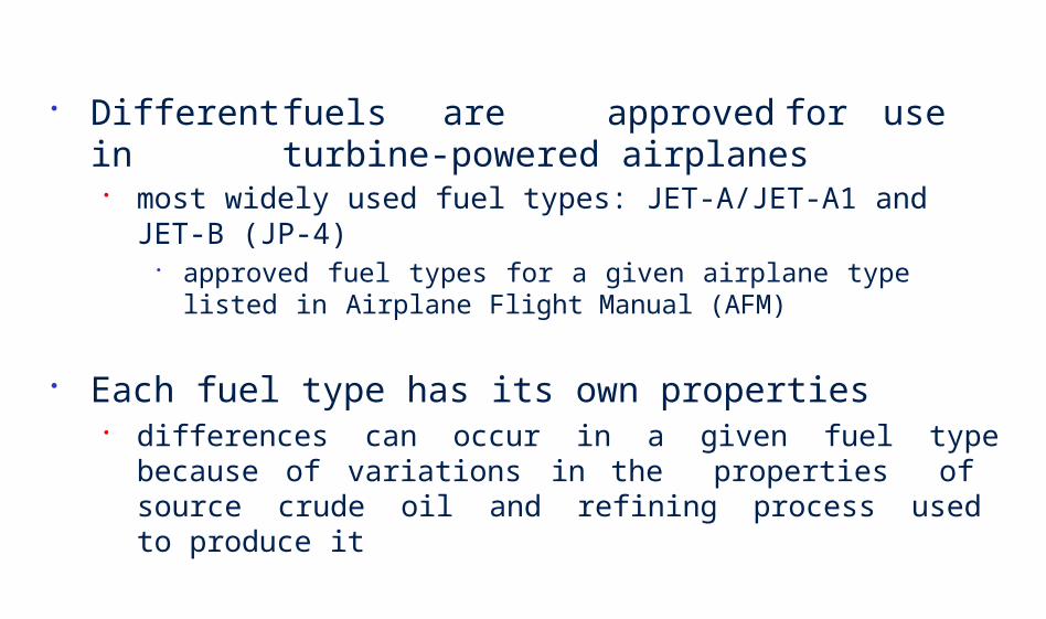
Different fuels are approved for use in turbine-powered airplanes
most widely used fuel types: JET-A/JET-A1 and JET-B (JP-4) approved fuel types for a given airplane type listed in Airplane Flight
Manual (AFM)
Each fuel type has its own properties differences can occur in a given fuel type because of variations
in the properties of source crude oil and refining process used to produce it

Flash Point lowest temperature at which the liquid supplies enough vapours
mixed with ambient air, to make a gas that will ignite with the contact of a thermal source
at this temperature the combustion will not be self sufficient, because you need to reach the ignition point
Ignition Point temperature at which the combustion is started and can
continue
Auto-Ignition temperature at which a gas or vapour ignites spontaneously in
the absence of a thermal source (e.g. Jet A: 450°F,sea level) it is a practice that max allowable surface temperature is at least
50°F below the lowest expected auto-ignition temperature of the approved fuels

FUEL TANK SAFETY(Level 2 Training)
Ignition Source Prevention

Regulatory authorities and aviation industry have always presumed that a flammable fuel/air mixture exists in the fuel tanks at all times
adopted philosophy that the best way to ensure airplane fuel tank safety is to preclude ignition sources within fuel tanks
based on application of fail-safe design requirements to the airplane fuel tank system to preclude ignition sources from being present in fuel tanks when component failures, malfunctions, or lightning encounters occur

Possible ignition sources include: electrical arcs
lightning electrostatic charging electromagnetic interference failures in airplane systems or wiring
friction sparks mechanical contact between rotating components in fuel tank
hot surface ignition or auto-ignition failure of components within fuel tank, or external components or systems
that cause components or tank surfaces to reach a high enough temperature to ignite the fuel vapours in the fuel tank
Conditions required to ignite fuel vapours from these ignition sources vary with pressures and temperatures within the fuel tank and can be affected by sloshing or spraying of fuel in the tank
Identify and address potential sources of ignition within fuel tanks and by possible external influences, which may not previously have been considered to be unsafe features
Each operator should review aircraft service records, flight logs, inspection records, and component supplier service records to assist in establishing any unforeseen failures, wear or other conditions that could result in an ignition source within the fuel system
Review of changes to components from original type design changes to components, and the use of Parts Manufacturer Approval
(PMA) parts following certification may have been done without consideration of possible effects of the changes to the requirements to preclude ignition sources
whilst aircraft manufacturer will be responsible for integrity of fuel system designed by them, they are not responsible for any effects that may be caused by installation of additional fuel tanks fitted by STC or other approved modification or alternate components fitted through PMA process

List of some discrepancies found:
Pumps Pump inducer failures resulting in ingestion of inducer into pump
impeller and generation of debris into fuel tank Pump inlet check valves failures resulting in rubbing on pump
impeller Stator windings have failed during operation of fuel pump
subsequent failure of a second phase of pump caused arcing through pump housing
Thermal protective features deactivated by inappropriate wrapping of pumps’ windings

Pumps Cooling port tubes omitted during pump overhaul
Extended dry running of fuel pumps in empty fuel tanks, causing failures
Use of steel impellers that might produce sparks if debris enters the pump
Debris found lodged inside pumps Pump power supply connectors corroded, allowing fuel leakage
and electrical arcing Electrical connections within pump housing exposed and
designed with inadequate clearance to pump cover, resulting in arcing
Re-settable thermal switches resetting at higher trip temperature

Pumps Flame arrestors falling out of their respective mounting
Internal wires coming in contact with pump rotating group, energising rotor and arcing at impeller/adapter interface
Poor bonding across component interfaces Insufficient ground fault current capability Poor bonding of components to structure Premature failure of fuel pumps thrust bearings, allowing steel
rotating parts to contact the steel pump side plate
Wiring to Pumps located in metallic conduits or adjacent to fuel tank walls
Wear of Teflon sleeving and wiring insulation, allowing arcing to conduit causing an ignition source in tank, or arcing to the tank wall

Fuel Pump Connectors Electrical arcing at connections within electrical connectors due
to bent pins or corrosion
Fuel Quantity Indication System (FQIS) Wiring Degradation of wire insulation (cracking) Corrosion (copper sulphate deposits) at electrical connectors Unshielded FQIS wires routed in wire bundles with high voltage
wires Corroded and loose terminations Excessive strain on the wiring

Fuel Quantity Indication System Probes Corrosion and copper sulphide deposits reduced breakdown
voltage in FQIS wiring FQIS wiring clamping features at electrical connections on fuel
probes damaged wiring and reduced breakdown voltage Contamination in fuel tanks and mechanical impact damage,
caused reduced arc path between FQIS probe walls
Failed or aged seals Seal deterioration may result in leaks internal or external to
fuel system, as well as fuel spraying

Bonding Straps Corrosion, inappropriately attached connections (loose or
improperly grounded attachment points) Static bonds on fuel system plumbing connections inside fuel tank
found worn due to mechanical wear of plumbing from wing movement and corrosion
Bonding points improperly sealed after access Worn and frayed bonding jumpers Incorrect bonding jumpers (manufactured from incorrect material)


Cleanliness Removal of any loose material, rivets, swarf, hardware, excess sealant, etc
Inspection of: All plumbing for damage, security, possible sources of abrasion and chaffing Quick disconnect fittings are secure and in good condition Plumbing is not distorted by clamps Wiring for any signs of degradation or overheating Wire routing is appropriate and properly secured Connectors are properly torqued and if appropriate lock wired Where a connector has been disturbed, inspect both male and female
connections for damage Insulation material deterioration Cable support for adequacy or potting for deterioration Contacts for damage and corrosion cleaned prior to reassembling Bonding jumpers and bonding points for damage, correct sealing, corrosion,
correct material and terminals Fuel Pumps are correctly mounted and secure Fuel system vents and vent heating elements, check condition and security
including any flame trap that may be installed and that vent is unobstructed


Effects of electrical transients from lightning, EMI, or HIRF on anything conductive (e.g. fuel tank plumbing, structure, fuel, equipment and wiring) within the fuel tanks, particularly for the fuel quantity indicating system wiring and probes
Impact from Pneumatic System Failures Leakage of air from ducting located near fuel tanks due to duct failure
resulting in undetected heating of tank surfaces above the auto-ignition temperature
Impact from Electrostatic Charge Buildup Use of non-conductive reticulated polyurethane foam that holds
electrostatic charge build up Spraying of fuel into fuel tanks through inappropriately designed refueling
nozzles Spraying of fuel into fuel tanks from fuel pump motor cooling flow return
ports that spray fuel into the tank


Minimise number of components and systems inside fuel tanks whose failure could result in an ignition source. Examples:
Wiring entering tank for such purposes as temperature monitoring and fuel quantity indication should be minimized
If practical, fuel pumps located such that electrical power for pumps is routed outside tanks in such a manner that failures in power supply cannot create hot spot inside tank or arc into tank
Separation of tank wires from higher energy carrying wires and shielding of tank wires; or installation of transient suppression devices, to preclude unwanted electrical energy from entering tank
Locating fuel pumps such that inlet remains covered with fuel throughout airplane operating envelope
Installation of baffles in tank structure and use of collector tanks that are continually filled with fuel using ejector pumps


FUEL TANK SAFETY(Level 2 Training)
Flammability Reduction

Centre-Wing-Tank (CWT) explosions
17th July 1996, B747-131, Registration N93119 - Flt No TWA 800 1990, B737-300, Philippine Air Lines
2001, B737-400, Thai Airways
Common Factors
Aircraft parked on ramp for some considerable time with high ambient temperature (+900F)
Centre Wing Tank empty Air-conditioning Packs running for some time

FAA believes added safety net of reducing flammability of the tank is also necessary
Notice of Proposed Rulemaking (NPRM) require aircraft operators to reduce flammability levels of fuel tank vapours to remove likelihood of potential explosion from ignition source (Nov 2005)
Amendment 25-102 added a new paragraph 25.981(c) minimization of the formation of flammable vapours in fuel
tanks, or mitigation of any hazards if ignition does occur intended to promote design practices that reduce exposure
to operation with flammable vapours in transport airplane fuel tanks to lowest practical level, equivalent to that of unheated wing tank
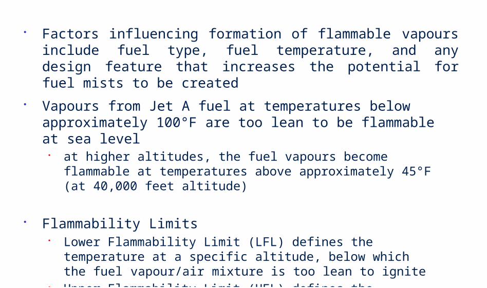
Factors influencing formation of flammable vapours include fuel type, fuel temperature, and any design feature that increases the potential for fuel mists to be created
Vapours from Jet A fuel at temperatures below approximately 100°F are too lean to be flammable at sea level
at higher altitudes, the fuel vapours become flammable at temperatures above approximately 45°F (at 40,000 feet altitude)
Flammability Limits Lower Flammability Limit (LFL) defines the temperature at a specific
altitude, below which the fuel vapour/air mixture is too lean to ignite Upper Flammability Limit (UFL) defines the temperature at a specific
altitude, above which the fuel vapour/air mixture is too rich to ignite
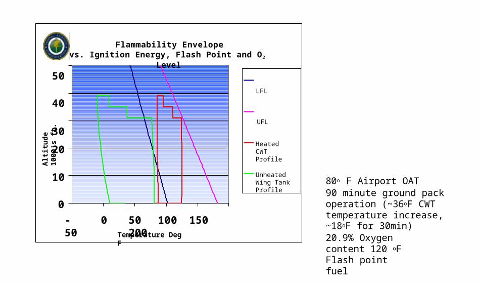
Flammability Envelopevs. Ignition Energy, Flash Point and O2 Level
50LFL
40
UFL
30
0
10
20
-50 0 50 100 150 200Temperature Deg F
Alt
itu
de
1000
's f
t.
Heated CWT Profile
Unheated Wing Tank Profile 80o F Airport OAT
90 minute ground pack operation (~36oF CWT temperature increase,~18oF for 30min)20.9% Oxygen content 120 oF Flash point fuel

Flammability Envelopevs. Ignition Energy, Flash Point and O2 Level
50LFL
40
UFL
30
0
10
20
-50 0 50 100 150 200Temperature Deg F
Alt
itu
de
100
0's
ft.
Heated CWT Profile
Unheated Wing Tank Profile
40o F Airport OAT90 minute ground pack operation (~45oF CWT temperature increase,~22oF for 30min)20.9% Oxygen content 120 oF Flash point fuel
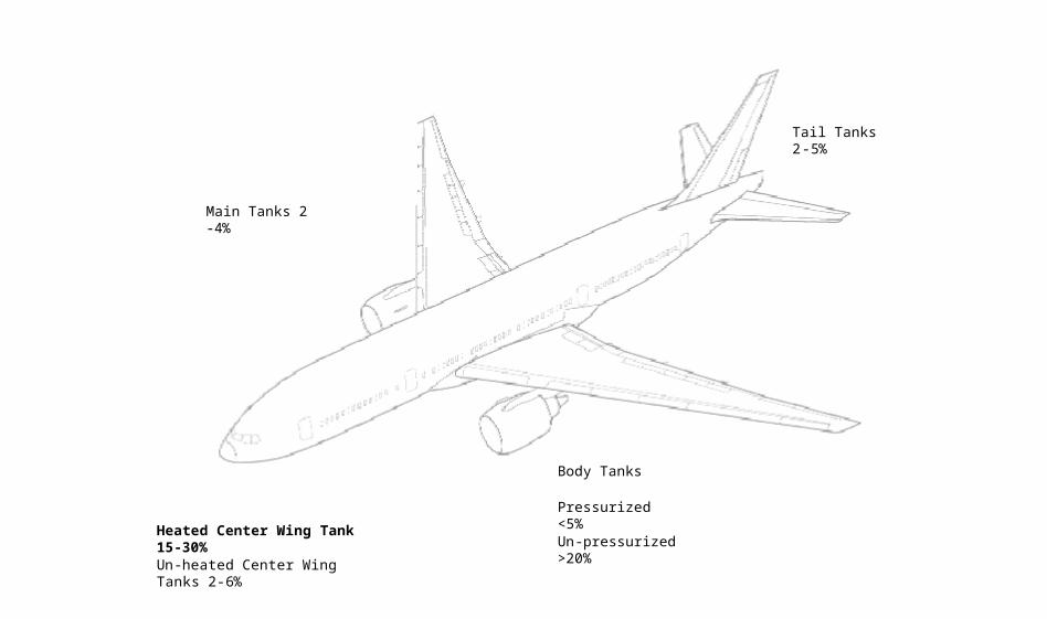
Main Tanks 2 -4%
Tail Tanks 2-5%
Body Tanks
Pressurized <5%
Un-pressurized >20%Heated Center Wing Tank 15-30%Un-heated Center Wing Tanks 2-6%

All airplanes designed with a Center Wing Tank are susceptible to flammability risk
including Airbus and Boeing models
CWT of following models considered high flammability:
Boeing -707, -737, -747, -757, -767, -777, for their centre wing tanks Airbus A300/310, A320 family, A330/340, for their centre wing tanks auxiliary tanks on Boeing DC-10 and DC-9/MD-80, and STCs
introducing unpressurised auxiliary tanks in cargo compartment

Transferring heat from fuel tank (via use of ventilation or cooling air)
if heat sources were placed in or near tanks that significantly increased formation of flammable fuel vapours in the tank
if tank is located in area of airplane where little or no cooling
Selective use of inerting on ground or in-flight particularly if fuel tank flammability is significantly higher in one
particular fuel tank or phase of flight


Misting and sloshing flammability of fuel vapours greatly influenced by agitation,
sloshing, or misting of fuel, which results in higher concentration of fuel molecules in ullage
install sufficient baffling in tanks to reduce sloshing returning any fuel used to cool fuel pumps to bottom of tank introducing fuel during refueling at bottom of tank through low velocity
nozzles
Fuel Types Use of any low flash point fuels must be analyzed if they
are proposed for use as an approved fuel may significantly increase operational exposure to flammable
vapours other minimization means, such as inerting, may be required to
mitigate exposure created by continuous use of such fuels

Fuel Tank Temperature auxiliary fuel tanks located in cargo compartment or pressurized
areas, tanks located in center wing box, and horizontal stabilizer tanks may have less ability to reject heat to ambient air
may be subject to heat sources from equipment located nearby in fuselage, such as air conditioning packs
use of thermal insulation blankets providing ventilation or dedicated cooling to remove excess heat from
areas adjacent to tank installing an air gap in spaces adjacent to fuel tanks and using a
fan during ground operation using ram air inlets for in-flight operation to transfer heat from
tank bleeding cool air from ECS packs into the air gap

Fuel Tank Ullage Sweeping positive ventilation system to “sweep” ullage of flammable
fuel vapour/air mixtures at rate that keeps ullage lean in spite of higher-than-desirable fuel temperature
should address any negative effects, such as sweeping unburned hydrocarbons into the atmosphere
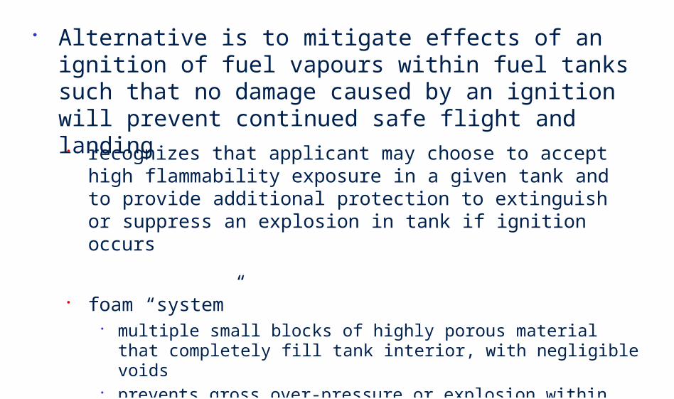
Alternative is to mitigate effects of an ignition of fuel vapours within fuel tanks such that no damage caused by an ignition will prevent continued safe flight and landing
recognizes that applicant may choose to accept high flammability exposure in a given tank and to provide additional protection to extinguish or suppress an explosion in tank if ignition occurs
foam “system” multiple small blocks of highly porous material that completely fill tank
interior, with negligible voids prevents gross over-pressure or explosion within a tank by limiting
extent of any vapour/air ignition to a small local detonation, preventing it propagating throughout the tank

Preference for fuel tank inerting in meeting new standards outlined in FAA’s proposed rule
Inert gas introduced into ullage so that oxygen content reduced to point where ignition and subsequent combustion is precluded
For the purpose of AC25.981-1B, tank is considered inert when oxygen content is less than 10% (inert gas: nitrogen)

Inerting may be achieved by supplying inert gas from: on-board storage bottles holding either gas or liquid inerting agent on board inert gas generation systems a ground storage system if tank is inerted only on the ground
Nitrogen is currently the inert gas of choice inexpensive minimal undesirable effects on fuel system and engines
‘Nitrogen Generation System’ (NGS) gas separation technology separate air into two exit streams
Nitrogen-Enriched-Air (NEA) Oxygen-Enriched-Air (OEA)

FAA onboard inerting prototype (May 2002) installed on a B747SP weighed about 200 pounds takes up very little space
FAA research also demonstrated that a higher level of oxygen (12%) could be used
Boeing proposed NGS on new production airplanes, and to make a similar system available for retrofit to in-service aircraft (2003)
NGS components located in air conditioning equipment bay on right side of airplane
EASA and FAA are in discussion on the harmonisation on this issue


N2
O2
CO2
H2O
Air
N2
O2, CO2, H2O

If you breathe air that does not have sufficient oxygen, health problems can occur.
Physiological effects of a low oxygen content environment (listed in decreasing oxygen level environment):
decrease in night vision, increase in breathing volume, increase in heartbeat rate (pulse)
increase in breathing and pulse rates, decrease in muscular coordination
emotional upset, unusual fatigue, trouble breathing nausea, vomiting, unable to do tasks, loss of consciousness intermittent breathing, unable to move, convulsions, death in
minutes
A person that breathes air with a low oxygen content cannot sense that the oxygen level is too low
victim can become unconscious he is aware of the low oxygen content air

Maintenance actions that require entry into a fuel tank that contains inert gas may be hazardous if appropriate safety precautions are not followed
Fuel tank should be ventilated and an appropriate air source provided
Appropriate warning information should be included in the Maintenance Manuals, and placards should be placed at fuel tank entry points to warn maintenance personnel of any hazards associated with maintenance actions or tank entry

NEA generated is routed safely to the center wing tank usual operation of NGS outside of fuel tanks is free from
concentrations of NEA
However, a duct leak, or component failure can cause NEA to go into areas outside of the fuel tanks
NEA leak can cause condition where oxygen content of air is decreased
Caution stencils and placards: installed on access doors adjacent to areas where potential NEA leakage can occur


FUEL TANK SAFETY(Level 2 Training)
Continued Airworthiness

Amendment 25-102 also require that critical design configuration control limitations, inspections, or otherprocedures be established, as necessary, to prevent development of ignition sources within the fuel tank system
included in the Airworthiness Limitations section of the Instructions for Continued Airworthiness (ICA)
requirement similar to that for airplane structure requirement to provide any mandatory fuel tank system
inspections or maintenance actions in the limitations section of the ICA

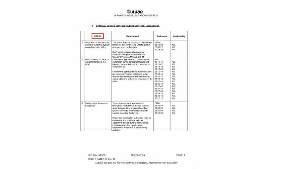
Critical Design Configuration Control Limitations (CDCCL)
include any information necessary to maintain those design features that have been determined by analysis of the fuel tank system as needed to preclude development of ignition sources
may include any maintenance procedure that could result in a failure, malfunction, or defect endangering the safe operation of the airplane, if not performed properly or if improper parts or materials are used
information is essential to ensure that maintenance, repairs, or alterations do not unintentionally violate the integrity of the original type design of the fuel tank system
Definition of CDCCL does not include all the features inherent in a design
includes only information necessary to ensure safety of fuel tank systems

Any fuel tank system components that are determined to require periodic maintenance, inspection, or overhaul to maintain the integrity of the system or maintain protective features incorporated to preclude a catastrophic fuel tank ignition event must be defined and included in the Limitations section of ICA
Examples of such items include:
Aging fuel line couplings seals/O-rings materials used in fuel line couplings may lose flexibility and harden
with age may allow air to enter the fuel line or leak, allowing spraying of fuel in
the tanks or other areas of the airplane where spraying fuel could create a fire hazard

Wear of pump bushings, bearings, and seals may significantly affect performance of fuel pumps and degradation of
features necessary to maintain explosive proof qualification
Fuel pump protective features
Transient suppression/energy limiting devices
Component grounds and wires, wire shield grounding
Fuel tank access panel/door seals
Fuel pump connectors, corrosion, wear
Fuel pump electrical supply conduit structural, sealing integrity

Visible means must be placed in areas of the airplane where maintenance, repairs, or alterations may violate the critical design configuration limitations
This essential information will be communicated by statements in appropriate manuals and be evident to those that may perform and approve such repairs and alterations
Acceptable means of providing visible means would include colour coding of the wiring or, for retrofit, placement of identification tabs at specific intervals along the wiring

Example: maintaining wire separation between FQIS wiring and other high power
electrical circuits where separation of the wiring was determined to be a critical design configuration control limitation

CDCCL should be identified in the airworthiness limitation section of ICA as an Airworthiness Limitation Item (ALI)
However, CDCCL are not inspections or life-limited items, as are most existing ALIs
CDCCL are features usually controlled by operators (or, where necessary, holders of type certificates or supplemental type certificates) through the development of appropriate procedures

As applied to fuel tank systems, ALI means fuel system mandatory instructions that can include design changes, maintenance, inspections, or procedures considered necessary to ensure that unsafe conditions do not arise in the fuel system throughout the operational life of the airplane
For each item identified as an ALI, the holder of a type certificate or a supplemental type certificate needs to develop instructions for design change, inspection and maintenance or procedural change
All changes to a CDCCL or ALI or a procedure involving a CDCCL or ALI must be approved by the appropriate regulatory office


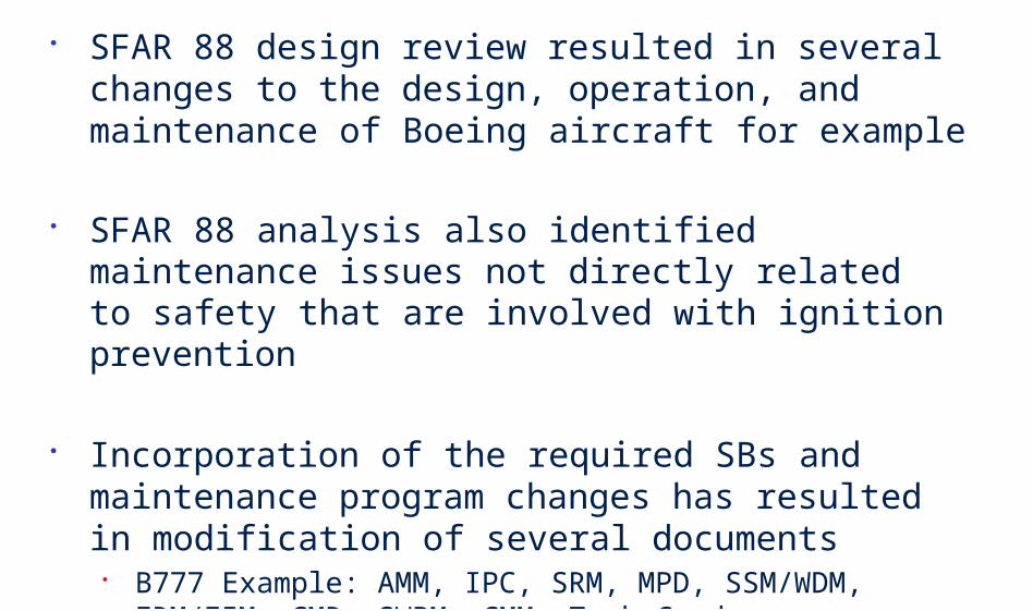
SFAR 88 design review resulted in several changes to the design, operation, and maintenance of Boeing aircraft for example
SFAR 88 analysis also identified maintenance issues not directly related to safety that are involved with ignition prevention
Incorporation of the required SBs and maintenance program changes has resulted in modification of several documents
B777 Example: AMM, IPC, SRM, MPD, SSM/WDM, FRM/FIM, CMR, SWPM, CMM, Task Cards, Airworthiness Limitations, etc


FUEL TANK SAFETY(Level 2 Training)
Fuel Tank Safety Precautions

Fuel tanks have two hazards: fire and toxic fumes
fuel vapour has an intoxicating effect
Fire precautions specified in governmental/local regulations should always be strictly observed
Make sure that you have the correct fire fighting equipment available

When you have to work on fuel system wiring, you must use test equipment that is approved
unapproved equipment could cause fire or an explosion
Make sure that lighting (explosion-proof lighting sources) in work area is sufficient to work safely
for work in areas where heavy fumes are present as inside fuel tanks, flameproof torches must be used
Wear protective goggles or face mask, clothes (100% cotton) and gloves and avoid wearing metallic clothing (e.g. footwear or a belt with a metal buckle) which can cause sparks

In the work area you must not:
smoke, use flames which do not have protection, operate electrical equipment which is not
necessary for the task, pull or move metal objects along the ground, use hearing-aids or battery-operated
equipment which will cause sparks, perform hot work, operate mobile phone or 2-way communication
within 15 metres of any open fuel tank

Put safety barriers in position and put up the required warning notices like not to operate the fuel system, not to refuel the aircraft, etc.
Defuel the applicable tank fuel tank valves closed drain remaining fuel purge tanks of fuel vapour before any inspection or
repair
Open and safety tag the required circuit breakers for the fuel system and others
Open the related fuel tanks access panels


Fuel tank is a confined space and has these hazards:
Risk of fire/explosions due to presence of flammable gases and vapours or due to an oxygen-enriched atmosphere
Risk of exposure to toxic fumes or substances
Risk of inadequate supply of oxygen

Poor natural ventilation
Poor natural lighting
Oxygen deficiency
Oxygen enrichment (potential fire hazard)
Presence of flammable gases/vapours
Presence of toxic fumes/substances

NOTE: Some of these precautions are the minimum safety standard for work in a fuel tank. Local regulations can make other safety precautions necessary
Before you can enter a confined space, you are required by to have a Confined Space Entry Permit.
Safety Assessor responsible for testing and monitoring atmosphere of
confined space regularly and filling information in Confined Space Entry Permit (must be certified)
Authorised Person check to ensure that readings in entry permit
are within permissible levels (approval by signing on permit)

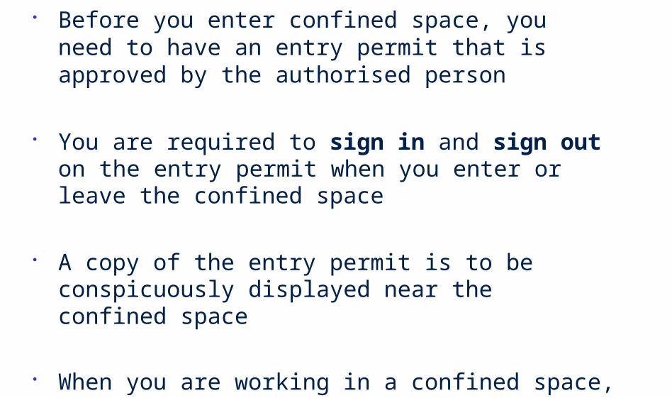
Before you enter confined space, you need to have an entry permit that is approved by the authorised person
You are required to sign in and sign out on the entry permit when you enter or leave the confined space
A copy of the entry permit is to be conspicuously displayed near the confined space
When you are working in a confined space, always ensure that there is an attendant outside the confined space to ensure safety and to respond to any emergency situation

If you are the authorised entrant, it is your duty to ensure that you:
Know what hazards may be present Have received proper briefing Wear necessary P.P.E. correctly Use only approved sparks-proof tools and approved
clothing Remove all sources of potential ignition Communicate with attendant Exit immediately when order is given by attendant To sign in and sign out on entry permit

If you are the attendant, it is your duty to ensure that you:
Know what hazards may be present Have received proper training Do not leave your appointed place Do not perform other duties Continuously maintain accurate count of authorised
entrants Maintain constant communication with entrants Summon rescue and other emergency services, in
case of emergency Evacuate the entrants if the ventilation system
fails
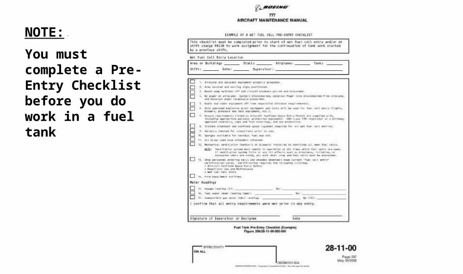
NOTE:
You must complete a Pre-Entry Checklist before you do work in a fuel tank

Finally, get access to the applicable work area

WARNING:
Do not touch or push against the magnetic level indicators when you are in the fuel tank
Do not touch or push against the FQI probes when you are in the fuel tank
Do not cause damage to the internal structure, sealant, electrical cables, or conduits during maintenance
Do not use metallic wire wool in fuel tanks
NOTE: You may have to remove parts of the structure (and equipment) to get access to parts of the tank

Use protective mats on the floor of fuel tank to prevent: damage to fuel tank structure
injury to persons
Safety all components before you place them inside the fuel tank
All wire locking must be installed/adjusted outside the fuel tank
Use only red tie wraps in the fuel tanks

Use only approved cleaning materials.
Make sure that all signs of solvents and cleaning agents are removed from the equipment/components before they are installed.
Put blanking caps on all disconnected pipes and openings in components and tanks.
Do not connect electrical equipment to a power source less than 30 meters away, unless the power source has spark-proof connectors.

You must obey the fuel safety procedures when you do work in a fuel tank. When differences occur, you must use the approved precautions of this procedure.
After completion of work in a fuel tank, personnel must make sure that:
Work area is clear of tools, Work area is clean, No electrical equipment has been damaged and
disconnected, All the fuel system components have a correct
electrical bonding, All access panels are back in their original position (e.g.
rib access panels).
Qn 1
Fuel that can be used for a particular airplane type :
(A)Is any type meant for the type of engines it has.
(B)Can be any type as long as it satisfy the required temperature characteristics.
(C)Are those approved types listed in the Airplane Flight Manual.

Qn 2
Use of low flash point fuels :
(A)Is restricted to tail tanks.
(B)May significantly increase operational exposure to flammable vapours.
(C)Mandates inerting to mitigate the associated hazards.

Qn 3
Auto-Ignition point is :
(A)Temperature at which the combustion is started and can continue.
(B)Temperature the combustion will not be self sufficient.
(C)Temperature at which a gas or vapour ignites spontaneously in the absence of a thermal source.

Qn 4
Factors influencing formation of flammable vapours include :
(A)Fuel type and fuel temperature only.
(B)Fuel temperature and any design feature that increases the potential for fuel mists to be created.
(C)Fuel type, fuel temperature, and any design feature that increases the potential for fuel mists to be created.

Qn 5
Flammability exposure of the Center Fuel Tank is deemed to be :
(A)More than the main tank or tail tanks.
(B)More than the tail tank but less than main tank.
(C)More than the main tank but less than tail tank.
Qn 6
Fuel Tank Ullage Sweeping can be used to :
(A)Cool fuel tanks that are exposed to external heat sources.
(B)Lower the Flash Point of the fuel tanks.
(C)Keep ullage lean with regard to flammable fuel vapour/air mixtures.

Qn 7
Fuel Tank Inerting :
(A)Means that the fuel tank design satisfies the requirements introduced by the new regulations.
(B)Uses an inert gas to reduce the oxygen content to the point where ignition and subsequent combustion is precluded.
(C)Refers to fuel tanks that are below a specified flammability level.

Qn 8
Critical Design Configuration Control Limitations (CDCCL) are :
(A)Inspection items.
(B)Found only in the Maintenance Planning Data document.
(C)For maintaining those fuel tank design features needed to preclude development of ignition sources.

Qn 9
Changes to a CDCCL or ALI or a procedure involving a CDCCL or ALI :
(A)Must be approved by the appropriate regulatory office.
(B)CDCCL changes must be approved by the appropriate regulatory office but not for ALI.
(C)ALI changes must be approved by the appropriate regulatory office but not for CDCCL.

Qn 10
For Fuel Tank Entry, the Safety Assessor :
(A)Is responsible for testing and monitoring atmosphere of the confined space regularly and filling information in Confined Space Entry Permit.
(B)Check to ensure that readings in entry permit are within permissible levels.
(C)Continuously maintain accurate count of authorised entrants.