FUEL SYSTEM - justanswer.com · 12/26/2008 · pushes air through the carburetor throat (venturi),...
29
3 B CARBURETOR 90-856159R02 SEPTEMBER 2002 Page 3B-1 FUEL SYSTEM Section 3B – Carburetor Table of Contents Specifications 3B-1 . . . . . . . . . . . . . . . . . . . . . . . . . . . Special Tools 3B-1 . . . . . . . . . . . . . . . . . . . . . . . . . . . Carburetor 3B-2 . . . . . . . . . . . . . . . . . . . . . . . . . . . . . Intake 3B-4 . . . . . . . . . . . . . . . . . . . . . . . . . . . . . . . . . . Carburetor Circuits 3B-6 . . . . . . . . . . . . . . . . . . . . . . Idle Circuit 3B-6 . . . . . . . . . . . . . . . . . . . . . . . . . . . Off-Idle Circuit 3B-7 . . . . . . . . . . . . . . . . . . . . . . . High Speed Circuit 3B-8 . . . . . . . . . . . . . . . . . . . Acceleration Circuit 3B-9 . . . . . . . . . . . . . . . . . . . Choke circuit 3B-10 . . . . . . . . . . . . . . . . . . . . . . . . . Carburetor Adjustments 3B-11 . . . . . . . . . . . . . . . . . . Idle Speed 3B-11 . . . . . . . . . . . . . . . . . . . . . . . . . . . Linkage 3B-11 . . . . . . . . . . . . . . . . . . . . . . . . . . . . . Choke 3B-14 . . . . . . . . . . . . . . . . . . . . . . . . . . . . . . Accelerator Adjustment 3B-15 . . . . . . . . . . . . . . . Carburetor Removal 3B-16 . . . . . . . . . . . . . . . . . . . . . Carburetor Disassembly 3B-18 . . . . . . . . . . . . . . . . . . Cleaning/Inspection/Repair 3B-20 . . . . . . . . . . . . . . . Carburetor Reassembly 3B-22 . . . . . . . . . . . . . . . . . . Float Height Measurement 3B-25 . . . . . . . . . . . . . Carburetor Installation 3B-26 . . . . . . . . . . . . . . . . . . . Electric Choke Models Installation 3B-26 . . . . . . Specifications CARBURETOR Idle rpm (Out Of Gear) Idle rpm (In Forward Gear) Wide Open Throttle rpm (WOT) Standard Model Range Bodensee Model Range Standard Model Main Jet Size 9.9 hp 15 hp Pilot Jet Bodensee Model Main Jet Size 9.9 hp 15 hp Pilot Jet Float Height 950 ± 50 rpm 850 ± 50 rpm 4500–5500 5200-5700 #68 #104 #45 #68 #103 #45 15.5 ± 1.0 mm (0.61 ± 0.04 in.) Special Tools 1. Carburetor Scale (Obtain Locally) 55847
Transcript of FUEL SYSTEM - justanswer.com · 12/26/2008 · pushes air through the carburetor throat (venturi),...

3B
CARBURETOR
90-856159R02 SEPTEMBER 2002 Page 3B-1
FUEL SYSTEMSection 3B – Carburetor
Table of ContentsSpecifications 3B-1. . . . . . . . . . . . . . . . . . . . . . . . . . . Special Tools 3B-1. . . . . . . . . . . . . . . . . . . . . . . . . . . Carburetor 3B-2. . . . . . . . . . . . . . . . . . . . . . . . . . . . . Intake 3B-4. . . . . . . . . . . . . . . . . . . . . . . . . . . . . . . . . . Carburetor Circuits 3B-6. . . . . . . . . . . . . . . . . . . . . .
Idle Circuit 3B-6. . . . . . . . . . . . . . . . . . . . . . . . . . . Off-Idle Circuit 3B-7. . . . . . . . . . . . . . . . . . . . . . . High Speed Circuit 3B-8. . . . . . . . . . . . . . . . . . . Acceleration Circuit 3B-9. . . . . . . . . . . . . . . . . . . Choke circuit 3B-10. . . . . . . . . . . . . . . . . . . . . . . . .
Carburetor Adjustments 3B-11. . . . . . . . . . . . . . . . . .
Idle Speed 3B-11. . . . . . . . . . . . . . . . . . . . . . . . . . . Linkage 3B-11. . . . . . . . . . . . . . . . . . . . . . . . . . . . . Choke 3B-14. . . . . . . . . . . . . . . . . . . . . . . . . . . . . . Accelerator Adjustment 3B-15. . . . . . . . . . . . . . .
Carburetor Removal 3B-16. . . . . . . . . . . . . . . . . . . . . Carburetor Disassembly 3B-18. . . . . . . . . . . . . . . . . . Cleaning/Inspection/Repair 3B-20. . . . . . . . . . . . . . . Carburetor Reassembly 3B-22. . . . . . . . . . . . . . . . . .
Float Height Measurement 3B-25. . . . . . . . . . . . . Carburetor Installation 3B-26. . . . . . . . . . . . . . . . . . .
Electric Choke Models Installation 3B-26. . . . . .
Specifications
CARBURETOR
Idle rpm (Out Of Gear)Idle rpm (In Forward Gear)Wide Open Throttle rpm (WOT)
Standard Model RangeBodensee Model Range
Standard ModelMain Jet Size9.9 hp15 hpPilot Jet
Bodensee ModelMain Jet Size9.9 hp15 hpPilot Jet
Float Height
950 ± 50 rpm 850 ± 50 rpm
4500–55005200-5700
#68#104#45
#68#103#45
15.5 ± 1.0 mm (0.61 ± 0.04 in.)
Special Tools
1. Carburetor Scale (Obtain Locally)
55847
2
3
4
5
6
7
89
10
1112
1314
15
16
17 18
19
20
21
22
23
24
31
32
25
26
27
28
29
30
33
34
1
35
CARBURETOR
Page 3B-2 90-856159R02 SEPTEMBER 2002
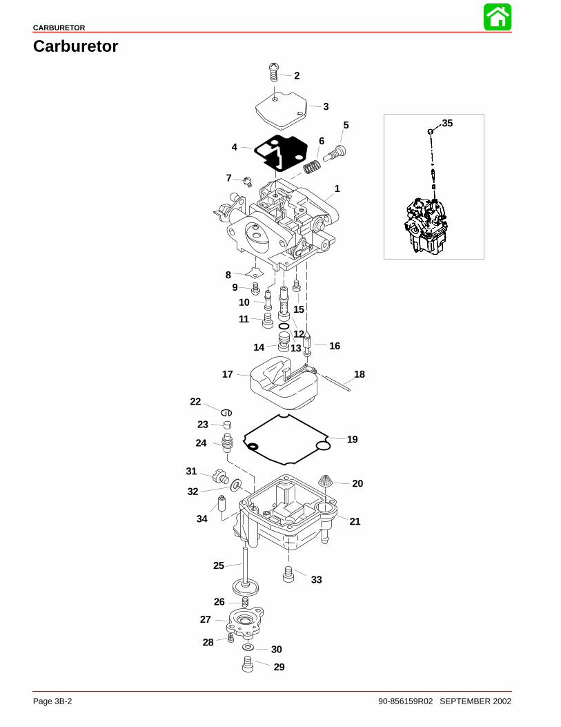
Carburetor

CARBURETOR
90-856159R02 SEPTEMBER 2002 Page 3B-3
Carburetor
REFTORQUE
REF.NO. QTY. DESCRIPTION lb-in. lb-ft Nm
1 CARBURETOR (15)
11 CARBURETOR (9.9)
11 CARBURETOR (9.9 BODENSEE)1 CARBURETOR (15 BODENSEE)
2 2 SCREW (M4x10) 17.7 23 1 COVER4 1 GASKET
5 1 THROTTLE SCREW6 1 SPRING-Pilot Adjusting7 1 SCREW (M4x5) Drive Tight8 1 PLATE9 1 SCREW (M3x5) Drive Tight10 1 PILOT JET (#45) 10.6 1.211 1 PLUG 17.7 2
1 MAIN NOZZLE (15) 17.7 2
12 1 MAIN NOZZLE (15 BODENSEE) 17.7 21 MAIN NOZZLE (ALL 9.9) 17.7 2
13 1 O RING1 MAIN JET (#104) (15) 10.6 1.2
14 1 MAIN JET (#103) (15 BODENSEE) 10.6 1.21 MAIN JET (#68) (ALL 9.9) 10.6 1.2
15 1 SCREW (M4x5) 17.7 216 1 NEEDLE VALVE17 1 FLOAT18 1 FLOAT PIN19 1 GASKET20 1 FILTER
211 FLOAT BOWL ASSEMBLY (15)
211 FLOAT BOWL ASSEMBLY (9.9)
22 1 RETAINING RING23 1 CAP24 1 SEAL25 1 DIAPHRAGM26 1 SPRING27 1 COVER
28 3 SCREW (M4x8) 17.7 229 1 DRAIN SCREW (M4x5) 17.7 230 1 GASKET31 1 DRAIN SCREW (M5x6) 34 4.532 1 GASKET Not Included with 9.9 Bowl33 4 SCREW (M4x12) 17.7 2
34 1 CHECK VALVE (15)35 1 SEAL (BODENSEE)

CARBURETOR
Page 3B-4 90-856159R02 SEPTEMBER 2002
Intake
1
3
4
5
6
7
8
910
11
12
13
2
3
6
110
4 Stroke Outboard Oil110

CARBURETOR
90-856159R02 SEPTEMBER 2002 Page 3B-5
Intake
REFTORQUE
REF.NO. QTY. DESCRIPTION lb-in. lb-ft Nm
1 1 INTAKE MANIFOLD2 1 GASKET3 2 DOWEL PIN4 4 BOLT (M6 x 40) 70 85 1 INSULATOR6 2 GASKET7 1 O RING
8 1 SILENCER9 DECAL-Warning, High Voltage10 1 PLATE11 2 COLLAR12 2 BOLT (M6 x 100) 88 1013 1 HOSE

CARBURETOR
Page 3B-6 90-856159R02 SEPTEMBER 2002
Carburetor Circuits
Idle Circuit
ÄÄÄÄ
a
b
c
d
e
f
gh
ij
k
l
m
a- Air Bleed Inletb - Float Bowl Vent Inletc - Idle Air Bleed Restrictord - Off-Idle Discharge Porte- Idle Discharge Portf - Throttle Valveg - Inlet Filterh - Fuel Inleti - Bowl Drainj - Main Jetk - Pilot Jetl - Choke Valve
m- Air FlowAs the engine rotates, the piston travel moves away from the open intake valve. Thismovement creates a low pressure area behind the throttle valve. Atmospheric pressurepushes air through the carburetor throat (venturi), past the throttle valve and into the lowpressure area inside the intake/cylinder.
Atmospheric pressure enters the float bowl chamber through the bowl vents. This pressureforces fuel toward the low pressure area behind the throttle valve. Fuel flows through themain fuel jet into the main fuel well, up the idle tube, through the pilot jet, past the off-idlepassages, past the idle mixture jet (not shown), into the idle passage, and into the carburetorthroat.
Air enters the idle circuit through the off-idle ports, before the air/fuel mixture is dischargedinto the engine.

CARBURETOR
90-856159R02 SEPTEMBER 2002 Page 3B-7
Off-Idle Circuit
ÄÄÄÄ
a
bc
de
f
g
hi
jk
l
a - Air Bleed Inletb - Float Bowl Vent Inletc - Idle Air Bleed Restrictord - Off-Idle Discharge Porte- Idle Discharge Portf - Throttle Valveg - Inlet Filterh - Bowl Draini - Main Jetj - Pilot Jetk - Choke Valvel - Air Flow
As the throttle valve rotates past the off-idle ports, the ports are exposed to the low pressurearea behind the throttle valve. Additional fuel flows through the off-idle passage, through therear port, and as the throttle valve continues to rotate, through the forward ports.
NOTE: The idle circuit will continue to supply fuel into the engine.

CARBURETOR
Page 3B-8 90-856159R02 SEPTEMBER 2002
High Speed Circuit
ÄÄÄÄÄÄ
a
bc
d
ef
g
h
i
a - Air Bleed Inletb - Float Bowl Vent Inletc - Idle Air Bleed Restrictord - Throttle Valvee- Inlet Filterf - Main Discharge Nozzleg - Main Jeth - Pilot Jeti - Air Flow
As the throttle valve rotates past the off-idle ports, the low pressure area extends to the maindischarge nozzle. In addition, the increased air flow through the carburetor bore creates alow pressure area inside the venturi. These combined forces create a strong suction overthe main discharge tube. Fuel flows through the main jet into the main fuel well, up the maindischarge nozzle, into the venturi.
Air is mixed with the fuel to make it lighter, air enters the main fuel well through the maindischarge air inlet tube. Cross holes (air bleeds) are drilled in the main discharge tube,allowing the air to mix with the fuel inside the main well. As the throttle valve continues toopen, additional fuel is drawn out of the main discharge tube, exposing additional crossholes. At full throttle, the fuel mixture is controlled by the size of the main fuel jet.
NOTE: Both the idle and off-idle circuits will continue to supply fuel into the engine.
CARBURETOR
90-856159R02 SEPTEMBER 2002 Page 3B-9
Acceleration Circuit
ÄÄÄÄ
a
bc
d
e
fg
h
i
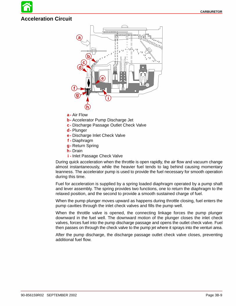
a - Air Flowb - Accelerator Pump Discharge Jetc - Discharge Passage Outlet Check Valved - Plungere- Discharge Inlet Check Valvef - Diaphragmg - Return Springh - Draini - Inlet Passage Check Valve
During quick acceleration when the throttle is open rapidly, the air flow and vacuum changealmost instantaneously, while the heavier fuel tends to lag behind causing momentaryleanness. The accelerator pump is used to provide the fuel necessary for smooth operationduring this time.
Fuel for acceleration is supplied by a spring loaded diaphragm operated by a pump shaftand lever assembly. The spring provides two functions, one to return the diaphragm to therelaxed position, and the second to provide a smooth sustained charge of fuel.
When the pump plunger moves upward as happens during throttle closing, fuel enters thepump cavities through the inlet check valves and fills the pump well.
When the throttle valve is opened, the connecting linkage forces the pump plungerdownward in the fuel well. The downward motion of the plunger closes the inlet checkvalves, forces fuel into the pump discharge passage and opens the outlet check valve. Fuelthen passes on through the check valve to the pump jet where it sprays into the venturi area.
After the pump discharge, the discharge passage outlet check valve closes, preventingadditional fuel flow.

CARBURETOR
Page 3B-10 90-856159R02 SEPTEMBER 2002
Choke circuit
ÄÄÄ
a
bc
de
a- Choke Valveb - Air Flowc - Main Discharge Tubed - Off-Idle Discharge Portse- Idle Discharge Port
The choke system consists of a choke valve, detent and a push/pull cable or electricsolenoid. The choke operation is controlled by the operator to determine enginerequirement and correctly position the handle on the cable or activate the electric solenoid.
When the engine is cold, the operator pulls the cable or activates the solenoid to close thechoke valve. As the engine is started, a low pressure area develops inside the carburetorventuri. Atmospheric pressure flows through the opening in the choke valve into the lowpressure area. Fuel is drawn into the air stream through the main discharge nozzle, off-Idledischarge ports, and idle discharge ports.
As the engine warms up the operator can reposition the choke valve or solenoid as desired.After the engine reaches operating temperature, the valve is returned to the fully openposition.
CARBURETOR
90-856159R02 SEPTEMBER 2002 Page 3B-11
Carburetor Adjustments
Idle SpeedNOTE: Before adjusting the idle speed make sure the throttle link rod has been properlyadjusted.
1. Measure the idle speed using the procedure below, adjust if necessary:
• Start engine and allow it to warm up.
• Attach a tachometer to the spark plug lead of cylinder #1.
• Measure idle rpm with outboard in neutral.
• Turn throttle stop screw in direction A or B until the specified idle speed isobtained.
NOTE: Turning throttle stop screw in (a) will increase idle speed while turning screw out (b)will decrease speed.
Idle rpm (Out Of Gear)
950 ± 50 RPM
a
b
LinkageREMOTE CONTROL MODELS
1. Connect throttle linkage and secure with screw.
NOTE: Linkage should extend 7 mm (0.28 in.) beyond barrel. Over-tightening screw maydamage throttle linkage.
a
b
c
a- Throttle Linkageb - 7 mm (0.28 in.) Lengthc - Screw

CARBURETOR
Page 3B-12 90-856159R02 SEPTEMBER 2002
TILLER HANDLE MODELS (SIDE SHIFT SHOWN)
1. Turn idle speed screw counterclockwise until screw is not touching throttle shaft arm.
ab
a- Idle Speed Screwb - Throttle Shaft Arm
2. Install throttle linkage on pulley and throttle barrel.
b
a
a
a- Throttle Linkageb - Throttle Barrel
3. Check to make sure throttle linkage is has free movement between throttle barrel andpulley.
NOTE: The throttle arm should remain stationary while checking for free movement ofthrottle linkage.
a
b
c
a- Throttle Barrelb - Pulleyc - Throttle Arm

CARBURETOR
90-856159R02 SEPTEMBER 2002 Page 3B-13
4. Move throttle linkage forward until linkage comes to rest on the pulley boss.
a b
a- Throttle Linkageb - Pulley Boss
5. Tighten screw on throttle barrel to secure linkage.
NOTE: Over-tightening screw may damage throttle linkage.
NOTE: Check linkage for free movement on pulley. Verify throttle shaft arm in not stickingand returns to idle position.
a
b
a- Screwb - Linkage
6. Verify throttle arm does not hit the full throttle stop at wide open throttle. Gap betweenstop and throttle arm should be no more than 2.54 mm (0.1 in.).
c
ab
a- Throttle Stopb - Throttle Armc - Approximately 2.54 mm (0.1 in.) Gap

CARBURETOR
Page 3B-14 90-856159R02 SEPTEMBER 2002
7. Turn idle speed screw in (clockwise) until it touches the throttle shaft arm, then turn anadditional 1/2 turn for initial setting.
a
b
a- Idle Speed Screwb - Throttle Shaft Arm
Choke1. Route choke cable through cable bracket and install retaining ring.
a
b
a- Choke Cableb - Retaining Ring
2. Set the choke cable to the off position (cable fully pushed in).
a
a- Choke Cable

CARBURETOR
90-856159R02 SEPTEMBER 2002 Page 3B-15
3. Set choke shutter to the off position (shutter lever rotated fully counterclockwise).
4. Thread the ball socket end on shaft until ball socket aligns with ball on carburetor. Snapsocket onto ball.
NOTE: Verify choke goes to full choke with cable pulled out and returns to off position withcable pushed in.
ab
c
a- Threaded Ball Socketb - Ballc - Shutter Lever
Accelerator Adjustment1. Adjust accelerator arm clearance to 0.254 mm (0.010 in.)
b c
ad
a- 0.254 mm (0.010 in.)b - Ballc - Threaded Ball Socketd - Shutter Lever

CARBURETOR
Page 3B-16 90-856159R02 SEPTEMBER 2002
Carburetor Removal1. Remove throttle linkage from carburetor barrel.
a
b
a- Barrelb - Throttle Link
2. Remove choke linkage (tiller handle models only).
a
a- Choke Linkage
3. Remove j-clips.
4. Disconnect breather hose from air intake and breather cover.
c
ab
d
a- J-Clips (2)b - Breather Hosec - Air Intaked - Breather Cover
CARBURETOR
90-856159R02 SEPTEMBER 2002 Page 3B-17
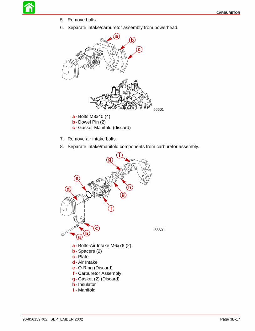
5. Remove bolts.
6. Separate intake/carburetor assembly from powerhead.
56601
ab
c
a- Bolts M8x40 (4)b - Dowel Pin (2)c - Gasket-Manifold (discard)
7. Remove air intake bolts.
8. Separate intake/manifold components from carburetor assembly.
56601
i
h
e
d
cb
a
f
g
g
a- Bolts-Air Intake M6x76 (2)b - Spacers (2)c - Plated - Air Intakee- O-Ring (Discard)f - Carburetor Assemblyg - Gasket (2) (Discard)h - Insulatori - Manifold

CARBURETOR
Page 3B-18 90-856159R02 SEPTEMBER 2002
Carburetor Disassembly
1. Remove drain screw.
NOTE: Use an acceptable container to hold gas when draining float bowl.
2. Remove float bowl.
3. Remove cover.
a
b
c
d
e
f
gh
i
a - Drain Screw-M5x6b - Gasket-Drain Screwc - Screws M4x12 (4)d - Float Bowle- Valvef - Gasket-Float Bowlg - Screw M4x10 (2)h - Coveri - Gasket

CARBURETOR
90-856159R02 SEPTEMBER 2002 Page 3B-19
4. Remove float assembly.
a
b
c
d
a- Screw-M4x5b - Pinc - Needle Valved - Float Assembly
5. Remove jets and nozzle.
a
b
c
d
e
f
g
a- Main Nozzleb - O-Ringc - Main Jetd - Pilot Jete- Seal Capf - Plateg - Screw-M3x5

CARBURETOR
Page 3B-20 90-856159R02 SEPTEMBER 2002
6. Remove diaphragm and filter.
gh
j
k
f
d
i
a
b
ce
a- Filterb - Screw-M4x5c - Gasket-Drain Screwd - Screws M4x8 (3)e- Basef - Springg - Ringh - Capi - Diaphragmj - Plungerk - O-Rings (2)
CARBURETOR
90-856159R02 SEPTEMBER 2002 Page 3B-21
Cleaning/Inspection/Repair
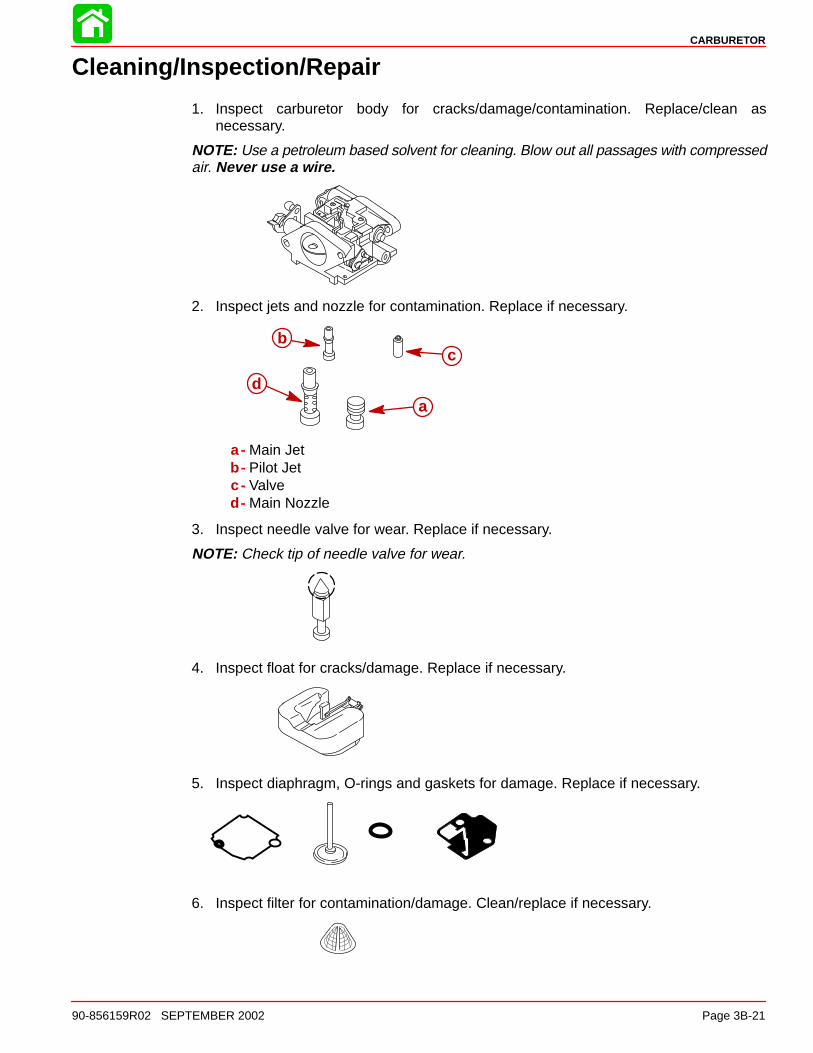
1. Inspect carburetor body for cracks/damage/contamination. Replace/clean asnecessary.
NOTE: Use a petroleum based solvent for cleaning. Blow out all passages with compressedair. Never use a wire.
2. Inspect jets and nozzle for contamination. Replace if necessary.
b
da
c
a- Main Jetb - Pilot Jetc - Valved - Main Nozzle
3. Inspect needle valve for wear. Replace if necessary.
NOTE: Check tip of needle valve for wear.
4. Inspect float for cracks/damage. Replace if necessary.
5. Inspect diaphragm, O-rings and gaskets for damage. Replace if necessary.
6. Inspect filter for contamination/damage. Clean/replace if necessary.

CARBURETOR
Page 3B-22 90-856159R02 SEPTEMBER 2002
Carburetor Reassembly
1. Install diaphragm and filter.
fg
h ij
ed
bk
ac
a- O-Rings (2)b - Plungerc - Diaphragmd - Cape- Ringf - Springg - Baseh - Screws M4x8 (3)i - Gasket-Drain Screwj - Screw M4x5k - Filter

CARBURETOR
90-856159R02 SEPTEMBER 2002 Page 3B-23
2. Install jets and nozzle.
a
bc
d
e
f
g
a- Plateb - Screw M3x5c - Pilot Jetd - Seal Cape- Main Nozzlef - O-Ringg - Main Jet
3. Install needle valve onto float hinge.
56677
b
c a
a- Floatb - Needle Valvec - Pin

CARBURETOR
Page 3B-24 90-856159R02 SEPTEMBER 2002
4. Install float assembly.
56676
a
bc
a- Floatb - Pin M4x5c - Screw
Float Height Measurement1. Measure float height as shown, if out of specification replace.
56675
P/N 91-36392
Carburetor Float Height
15.5 ± 1.0 mm (0.61 ± 0.04 in.)or
36/64 in. - 41/64 in.
CARBURETOR
90-856159R02 SEPTEMBER 2002 Page 3B-25
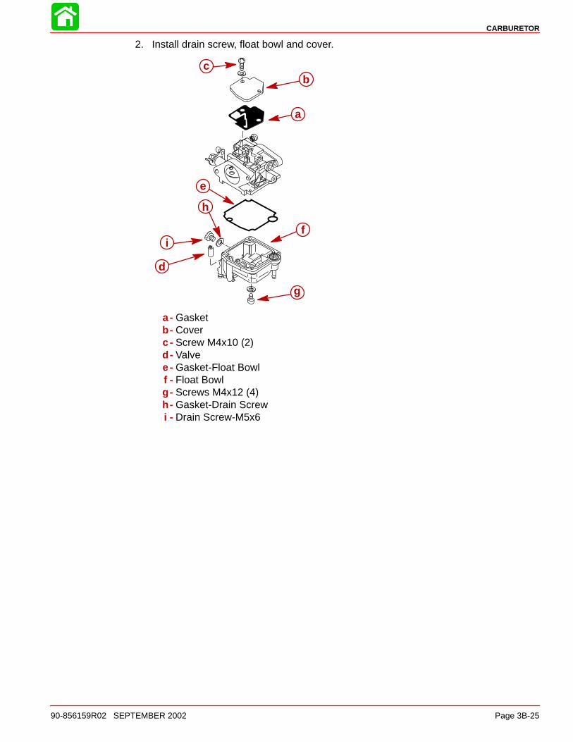
2. Install drain screw, float bowl and cover.
cb
a
e
i
d
h
g
f
a - Gasketb - Coverc - Screw M4x10 (2)d - Valvee- Gasket-Float Bowlf - Float Bowlg - Screws M4x12 (4)h - Gasket-Drain Screwi - Drain Screw-M5x6

CARBURETOR
Page 3B-26 90-856159R02 SEPTEMBER 2002
Carburetor InstallationElectric Choke Models Installation
1. Assemble solenoid components as shown.
a
bc
d
ef
a - Couplinga- Grommetb - O-Ringc - Hookd - Solenoide- Bracketf - Solenoid Mounting Screw M5x8 (2)
Solenoid Mounting Screw Torque
3.4 Nm (30 lb-in.)
2. Install solenoid to carburetor assembly. Push grommet over pin and secure spring tocarburetor with O-ring.
56750
ab
c
a- Solenoid Assemblyb - Grommetc - O-Ring

CARBURETOR
90-856159R02 SEPTEMBER 2002 Page 3B-27
3. Install solenoid bracket to powerhead with screws M6x16 (2). Connect BLUE toYELLOW/BLACK and BLACK lead to BLACK lead from remote control.
56751
a
b
a- Screw M6x16 (2)b - Solenoid Bracket
Solenoid Mounting Bracket Screw Torque
8 Nm (71 lb-in.)

CARBURETOR
Page 3B-28 90-856159R02 SEPTEMBER 2002
4. Assemble intake/manifold components to carburetor assembly.
5. Secure air intake with screws
56601
ab
cb
d
e
h
fg
i
a - Manifoldb - Gasket (2) (new)c - Insulatord - Carburetor Assemblye- O-Ring (New)f - Plateg - Spacersh - Air Intakei - Screw M6x 100 (2)
Carburetor Mounting Screw Torque
10 Nm (89 lb-in.)

CARBURETOR
90-856159R02 SEPTEMBER 2002 Page 3B-29
6. Install intake/carburetor assembly onto powerhead.
56601
a
bc
d
a- Gasket-Manifold (new)b - Dowel pin (2)c - Intake/Carburetor Assemblyd - Screw M6x40 (4)
Manifold Mounting Screw Torque
8 Nm (71 lb-in.)
7. Install j-clips.
8. Connect breather hose to air intake and route hose through j-clips.
a b
a- J-clips (2)b - Breather hose