
Fuel Cells: electrifying chemistry! - WSU Labs | … fuel cell hybrid loco PRWLYH´$ 5 0LOOHU . 6...
63
Transcript of Fuel Cells: electrifying chemistry! - WSU Labs | … fuel cell hybrid loco PRWLYH´$ 5 0LOOHU . 6...

2/63© Clean Energy Systems Integration Lab, 2016
Fuel Cells: electrifying chemistry!
What are they & How they work
Automotive Future
Other Fuel Cell Applications
CESI Lab Research interests
3/63© Clean Energy Systems Integration Lab, 2016
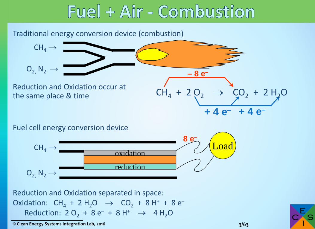
Traditional energy conversion device (combustion)
CH4 →
O2, N2 →
Reduction and Oxidation occur at the same place & time
Fuel cell energy conversion device
CH4 →
O2, N2 →
Reduction and Oxidation separated in space:Oxidation: CH4 + 2 H2O CO2 + 8 H+ + 8 e–
Reduction: 2 O2 + 8 e– + 8 H+ 4 H2O
– 8 e–
+ 4 e– + 4 e–
CH4 + 2 O2 CO2 + 2 H2O
oxidation
reduction
Load8 e–
4/63© Clean Energy Systems Integration Lab, 2016
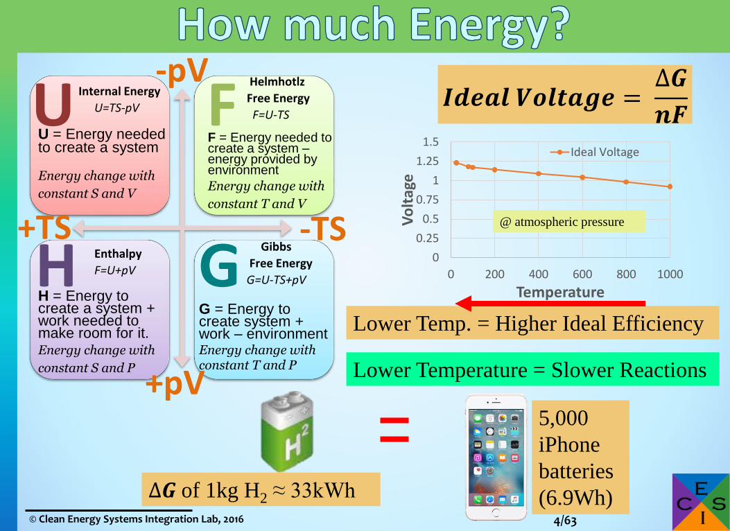
Internal Energy
U=TS-pV
U = Energy needed to create a system
Energy change with
constant S and V
UHelmhotlz
Free Energy
F=U-TS
F = Energy needed to create a system –energy provided by environment
Energy change with
constant T and V
F
Gibbs
Free Energy
G=U-TS+pV
G = Energy to create system + work – environmentEnergy change with constant T and P
GEnthalpy
F=U+pV
H = Energy to create a system + work needed to make room for it.Energy change with
constant S and P
H
+pV
-TS
-pV
+TS
𝑰𝒅𝒆𝒂𝒍 𝑽𝒐𝒍𝒕𝒂𝒈𝒆 =∆𝑮
𝒏𝑭
0
0.25
0.5
0.75
1
1.25
1.5
0 200 400 600 800 1000
Vo
ltag
e
Temperature
Ideal Voltage
Lower Temp. = Higher Ideal Efficiency
Lower Temperature = Slower Reactions
∆𝑮 of 1kg H2 ≈ 33kWh
5,000
iPhone
batteries
(6.9Wh)
@ atmospheric pressure

5/63© Clean Energy Systems Integration Lab, 2016
Limitations:a) Activation energy (giving a push)
b) Ohmic Losses (drag)
c) Concentration losses (traffic jam)
1.23 V
Higher Power Density =
Less Efficient
Heat
PowerMore Power

6/63© Clean Energy Systems Integration Lab, 2016
Loade
Product Gases
Residual Fuel
Fuel Oxidant
Anode CathodeElectrolyte
(Ion Conductor)
Product Gases
Residual Oxidant
ee
Phosphoric Acid: PAFC &Proton Exchange
Membrane: PEMFCH2
H2O
O2H+
Molten Carbonate: MCFCH2
CO2
H2O
CO3
CO2
O2
200C
90C
650C
Alkaline: AFC H2
H2OO2 80COH
–
Solid Oxide: SOFCH2
H2OO O2
700 -
1000C

7/63© Clean Energy Systems Integration Lab, 2016
Loade
Product Gases
Residual Fuel
Fuel Oxidant
Anode CathodeElectrolyte
(Ion Conductor)
Residual Oxidant
ee
AFCH2
O2 80CH2O
OH–
H2O
Space shuttle alkaline fuel cell
14”x15”x40” & weighs 255 lb
12kW peak, 7kW continuous
3 modules per shuttle

8/63© Clean Energy Systems Integration Lab, 2016
http://h2forum2008.ru/docs/pdf/23/s2/p3/4.pdf

9/63© Clean Energy Systems Integration Lab, 2016
Loade
Residual Fuel
Fuel Oxidant
Anode CathodeElectrolyte(Ion Conductor)
Product Gases
Residual Oxidant
ee
PAFC H2H2O
O2H+
~200C
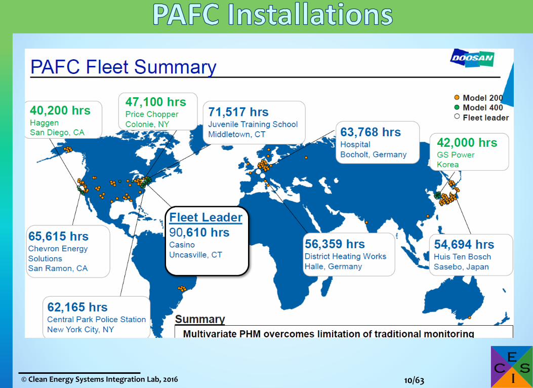
PAFC: H3PO4, SiC silicone carbide support, 150ºC and 210ºC
* Electrical efficiency of between 37% & 42% --higher with CHP
* 10 year lifespan
440KW PAFC – Doosan
Fuel Cell America
10/63© Clean Energy Systems Integration Lab, 2016
11/63© Clean Energy Systems Integration Lab, 2016
Loade
Residual Fuel
Fuel Oxidant
Anode CathodeElectrolyte(Ion Conductor)
Product Gases
Residual Oxidant
ee
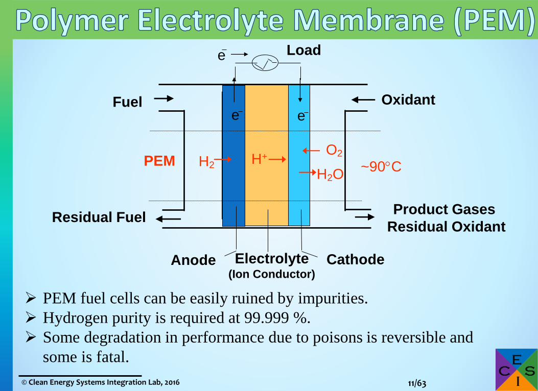
PEM H2H2O
O2H+
~90C
PEM fuel cells can be easily ruined by impurities.
Hydrogen purity is required at 99.999 %.
Some degradation in performance due to poisons is reversible and
some is fatal.

12/63© Clean Energy Systems Integration Lab, 2016
Gas
dif
fusi
on
layer
Electro
lyte
Carbon supported catalyst
Water collects around the
clusters of hydrophylic
sulfonate side chains
Sulphonated
fluoroethylene

13/63© Clean Energy Systems Integration Lab, 2016
Loade
Product Gases
Residual Fuel
Fuel
Anode CathodeElectrolyte
(Ion Conductor)
Residual Oxidant
ee
Oxidant
(O2, CO2)
O2
MCFC
H2
CO2
H2O
CO3
CO2
550-
650C

14/63© Clean Energy Systems Integration Lab, 2016
Loade
Product Gases
Residual Fuel
Fuel
Anode CathodeElectrolyte
(Ion Conductor)
Residual Oxidant
eeOxidant
SOFCH2
H2OO O2
700 -
1000C

15/63© Clean Energy Systems Integration Lab, 2016
Two geometry types primarily used in SOFC technology

16/63© Clean Energy Systems Integration Lab, 2016
» BloomEnergy, Versa Power, CFCL, SOFC Power, Ceres, SolidPower, NexCeris…
» Stacking with interconnect and manifold plates

17/63© Clean Energy Systems Integration Lab, 2016
A single fuel cell will typically produce between 0.5 to 0.8V.
In order to meet application reasonable voltages fuel cells
are connected in series.

18/63© Clean Energy Systems Integration Lab, 2016
» PEM fuel cells˃ Low temperature – require catalyst & pure H2
˃ Great for transportation applications (fast start)
˃ Goal is 5,000 hour lifespan
» MCFC & SOFC˃ High temperature – fuel flexible
˃ Stationary power
˃ Goal is 80,000 hour lifespan

19/63© Clean Energy Systems Integration Lab, 2016
Fuel Cells: electrifying chemistry!
What are they & How they work
Automotive Future
Other Fuel Cell Applications
CESI Lab Research interests
20/63© Clean Energy Systems Integration Lab, 2016
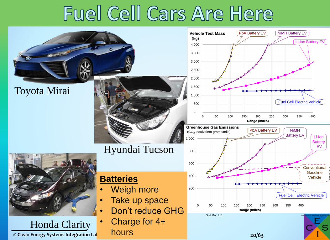
Honda Clarity
Toyota Mirai
Hyundai Tucson
BPEV.XLS; 'Compound' AS146 5/13 /2009
-
500
1,000
1,500
2,000
2,500
3,000
3,500
4,000
0 50 100 150 200 250 300 350 400
Range (miles)
Vehicle Test Mass
(kg)
PbA Battery EV
Li-Ion Battery EV
NiMH Battery EV
Fuel Cell Electric Vehicle
Grid Mix: US BPEV.XLS; 'Compound' AQ200 5/13 /2009
-
200
400
600
800
1,000
0 50 100 150 200 250 300 350 400
Range (miles)
Greenhouse Gas Emissions (CO2 -equivalent grams/mile) PbA Battery EV
Li-Ion
Battery
EV
NiMH
Battery EV
Fuel Cell Electric Vehicle
Conventional
Gasoline
VehicleBatteries
• Weigh more
• Take up space
• Don’t reduce GHG
• Charge for 4+
hours

21/63© Clean Energy Systems Integration Lab, 2016

22/63© Clean Energy Systems Integration Lab, 2016

23/63© Clean Energy Systems Integration Lab, 2016
High Voltage Junction Box
Motor Control Unit
Air Blower
Fuel Cell Stack
Humidifier
Demineralizer
Fuel Processing System
Controller
To Radiator
Hydrogen Recirculation
Blower
From Radiator
Air Filter

24/63© Clean Energy Systems Integration Lab, 2016
Traction MotorGear Reduction
Unit
Heater
3 way valveWater pump
Silencer

25/63© Clean Energy Systems Integration Lab, 2016
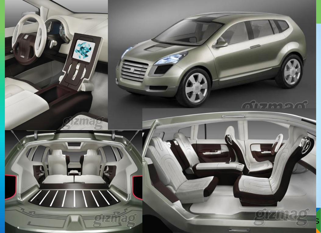
Sedan
SUV

26/63© Clean Energy Systems Integration Lab, 2016
27/63© Clean Energy Systems Integration Lab, 2016

28/63© Clean Energy Systems Integration Lab, 2016
CSULA hosted Mercedes
Benz F-Cell World Drive
with Cristian Maier, March
8, 2011

29/63© Clean Energy Systems Integration Lab, 2016

30/63© Clean Energy Systems Integration Lab, 2016
•Asia Toyota –Hino [dual automotive FC]
Hyundai
China ---in 4th generation
development, said to be well funded
•Europe Daimler
Van Hool/UTC/AC Transit
VDL/Kiepe/Ballard –18M flex bus
Hydrogenics –mini-bus
H2 Bus (HICE, in development)?
Skoda [“triple hybrid”, 85kW Proton
motor, U-cap
Wright/ISE
•USA • New Flyer/ISE/Ballard [150kW or
75kW, battery or U-Cap]
• E-Bus [22’, 20kW?]
• Proterra [35’, 32kW]
• El Dorado/BAE/Ballard –“American
FCB”

31/63© Clean Energy Systems Integration Lab, 2016
• All-Electric Drive Rooftop Cooling
• All Electric HVAC System
• Electric-Drive Power Steering
and Air Compressor
• Active Regenerative Braking
• Liquid Cooled Lithium-Ion
Battery System
• Rooftop 40 Kg H2 Storage
• Two 85 kW Siemens Drive Motors
• 164,000 miles (since Aug 2010)
• > 10,500 Fuel Cell Hours (for fleet)
AC Transit Fueled Bus

32/63© Clean Energy Systems Integration Lab, 2016

33/63© Clean Energy Systems Integration Lab, 2016

34/63© Clean Energy Systems Integration Lab, 2016
Fuel Cells: electrifying chemistry!
What are they & How they work
Automotive Power Past & Future
Other Fuel Cell Applications
CESI Lab Research interests

35/63© Clean Energy Systems Integration Lab, 2016
September 2009, Ohio State University Buckeye Bullet 2 set the world
record of 302 mph http://www.buckeyebullet.com/press.html
Intelligent Energy
Cal State Los Angeles
fuel cell racer
In 2007, a team of Ford engineers retrofitted the production Ford Fusion into
Hydrogen vehicle with fuel cells and set a world record of 200 mph

36/63© Clean Energy Systems Integration Lab, 2016
• Liquid oxygen and hydrogen is stored
in metal-hydride outside of the
pressure hull.
• The 120 kW BZM 120 Siemens fuel
cell has dimensions of 176x53x50 cm
and mass of 900 kg.

37/63© Clean Energy Systems Integration Lab, 2016
Figure 1. BNSF 1205, the largest fuel cell powered shunt locomotive and land vehicle, June 2009
(http://www.fuelcellpropulsion.org/projects.html) (left). Fuel cell locomotive principal systems layout (“System design of a
large fuel cell hybrid locomotive” A. R. Miller, K. S. Hess, D. L. Barnes, and T. L. Erickson, “System design of a large fuel
cell hybrid locomotive.” Journal of Power Sources, 173 (2007) 935-942) (right).

38/63© Clean Energy Systems Integration Lab, 2016
Figure 1. “PowerCar” developed by Russian National Railroads for working in enclosed conditions such as tunnels
(http://fotki.yandex.ru/users/serokoy/view/436236/?page=1).
Alkaline, leftovers from the space program

39/63© Clean Energy Systems Integration Lab, 2016
Fuel Cell APU applied to landing gear
http://www.dlr.de
The Boeing designed the very first manned fuel
cell airplane 2008 (Photo Credit: Boeing photo)
http://www.airbus.com/fileadmin/media_gallery/photoga
llery/big/800x600_1347473821_ILA-Berlin_Fuel-cell-
tailcone.jpg
40/63© Clean Energy Systems Integration Lab, 2016
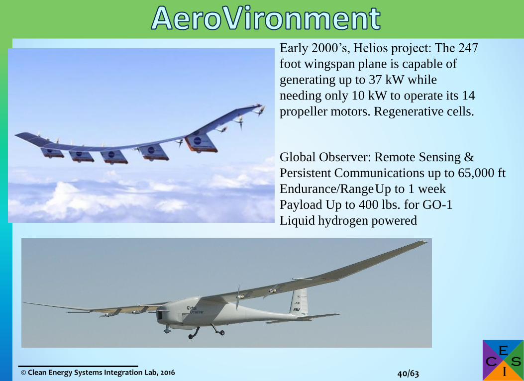
Early 2000’s, Helios project: The 247
foot wingspan plane is capable of
generating up to 37 kW while
needing only 10 kW to operate its 14
propeller motors. Regenerative cells.
Global Observer: Remote Sensing &
Persistent Communications up to 65,000 ft
Endurance/RangeUp to 1 week
Payload Up to 400 lbs. for GO-1
Liquid hydrogen powered
41/63© Clean Energy Systems Integration Lab, 2016
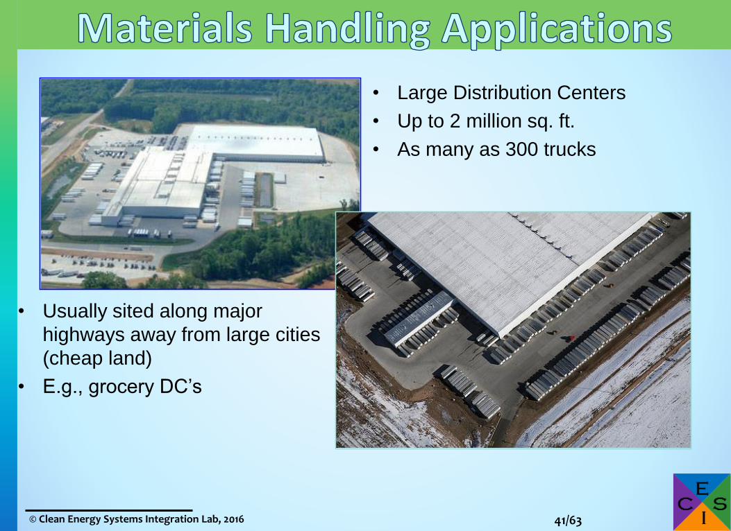
• Large Distribution Centers
• Up to 2 million sq. ft.
• As many as 300 trucks
• Usually sited along major
highways away from large cities
(cheap land)
• E.g., grocery DC’s

42/63© Clean Energy Systems Integration Lab, 2016
Class 1
Sit-down lift trucks: Handle heavy loads in large
manufacturing operations
Stand-up reach trucks:Provide flexibility and
maximum floor space
Utilization in large
distribution centers
Rider pallet trucks:Select goods within large
distribution centers before
delivery to retail stores
Class 3Class 2
Courtesy: Plug Power, 2013

43/63© Clean Energy Systems Integration Lab, 2016
Backup & Transportable Power
Ballard Power
Systems
Plug Power
Smart Fuel Cell
Intelligent Energy
Ball Aerospace
Manhattan Scientifics
Plug Power
Plug Power
Plug Power
Ballard
IdaTech
Altergy
JadooIntelligent Energy

44/63© Clean Energy Systems Integration Lab, 2016
» Cellular Communications Equipment
http://energy.gov/sites/prod/files/2014/10/f19/ftco_early_mkts_fc_backup_power_fact_sheet.pdf

45/63© Clean Energy Systems Integration Lab, 2016
http://energy.gov/sites/prod/files/2014/03/f12/mt_moreland_apco_presentation.pdf

46/63© Clean Energy Systems Integration Lab, 2016
» Cellular Communications Equipment (most popular)
http://energy.gov/sites/prod/files/2014/10/f19/ftco_early_mkts_fc_backup_power_fact_sheet.pdf

47/63© Clean Energy Systems Integration Lab, 2016
» Google» eBay» Microsoft» Apple» JPMorgan Chase» Verizon» Fujitsu» NTT» Williams-Sonoma
Apple

48/63© Clean Energy Systems Integration Lab, 2016
Distributed & Central Power Generation˃ Significant markets emerging
+ Landfill/digester
+ Combined heating and power
Siemens Power
Santa Rita Jail, CA
San Diego Sheraton, CACal State Northridge
Sierra Nevada Brewery, CA
King County, WAEarly DFC 1500®,
Danbury, CT
Residential
Power

49/63© Clean Energy Systems Integration Lab, 2016
» Japan’s Ene-Farm has most # of units sold
» Korea leads in large stationary power, but US is gaining˃ Primarily FuelCell Energy and Bloom
» Europe, even with many FC companies, lags behind

50/63© Clean Energy Systems Integration Lab, 2016
Ceres power (UK)

51/63© Clean Energy Systems Integration Lab, 2016
Fuel Cells: electrifying chemistry!
What are they & How they work
Automotive Power Past & Future
Other Fuel Cell Applications
CESI Lab Research interests

52/63© Clean Energy Systems Integration Lab, 2016
Farming
Manufacturing/Industry
Electricity
GenerationTransport
of Goods
Services/Offices

53/63© Clean Energy Systems Integration Lab, 2016
Farming
Manufacturing/Industry
Electricity
Generation
Transport
of Goods
Services/Offices

54/63© Clean Energy Systems Integration Lab, 2016
» Capture curtailed renewable energy in a convenient storage medium H2
Electrolyzer Fuel Cell
O2
H2
Fuel
Cell
Storage

55/63© Clean Energy Systems Integration Lab, 2016
Inlet Flow
Manifold
Inlet Flow Manifold
McLarty et al. International Journal of Hydrogen Energy 2013

56/63© Clean Energy Systems Integration Lab, 2016

57/63© Clean Energy Systems Integration Lab, 2016
% Self Generation
Baseline Grid Cost
Co
st
Max
Best NPC savings
Largest CHP for break-even
(best emissions reduction)

58/63© Clean Energy Systems Integration Lab, 2016
Choose A Building
Select State/Utility
Add Chillers/TES
View Results Choose Dispatch
Edit Costs
Pick A Fuel Cell
Add Wind/Solar
16 16 5

59/63© Clean Energy Systems Integration Lab, 2016
0
10
20
30
40
50
60
70
2000
2500
3000
3500
4000
4500
5000
5500
De
man
d m
et b
y D
G (
%)
Inst
alle
d F
C c
ost
($
/kW
)

60/63© Clean Energy Systems Integration Lab, 2016
McLarty, D., and J. Brouwer. “Poly-generating closed cathode fuel cell with carbon capture.” Applied Energy, 131, 108-116
Differences from standard SOFC:• Pressurized, pure O2 cathode increases FC efficiency • Higher anode H2 concentration increases FC efficiency• Waste heat captured in chemical potential of H2
• Cryogenic air separation synergistically produces O2 for FC and liquid N2 for the carbon liquefaction and H2 recovery

61/63© Clean Energy Systems Integration Lab, 2016
Reformer
Anode
Cathode
N2l 77K
+-
ASU
HSUCond-enser WGS
Fuel
Air
800K
1000K
900K
O2g 298K 900K
Heat, 1000K
(H2, CO2) 298K
(H2, CO2, H2O) 485K
H2gLiquid CO2
Recovery
(H2, CO2, H2O, CO)473K
Ammonia Production
N2g Liquid Ammonia
(NH3) Production
Heat, 500K
Oxy-FC can provide ultra-efficient, carbon free, fertilizer production!• The Oxy-FC concept is readily integrated with the standard Haber-Bosch process of ammonia
synthesis by passing the exhaust N2 and H2 streams over a catalyst bed to form NH3
• Ammonia production consumes 3% of the worlds fossil fuel at less than 50% thermal efficiency• Eliminates steam reforming, partial oxidation, shift reactors, and gas refining from ammonia plant

62/63© Clean Energy Systems Integration Lab, 2016
C T
Air Exhaust
ExhaustAir
Heat
100kW700kW
400kW
FC-GT Hybrid Challenges:1. Air flow rate & temperatures must match2. Off-design, GT flow doesn’t change, FC does3. Large plenum volume, stall/surge risk

63/63© Clean Energy Systems Integration Lab, 2016
Standard
FC-GT
Air @ 15 barITM
O2 at 15bar
(H2, CO2, H2O, CO)
Reformer
Anode
Cathode+-
Fuel800K
1000K
900K
Exhaust
Compressor Turbine
Air
O2 at 0.5bar
Combustor
Fuel
Depleted
Air
Generator
New De-Coupled FC-GT
Differences from standard FC-GT• Potential for retrofit to existing
systems• Eliminates costly high
temperature heat exchangers• FC not directly in working flow
risking surge/stall• Independent control of GT flow
and FC flow• Higher efficiency operating
condition for fuel cell• Potential for low emission
combustion

![DURABILITY OF FUEL PUMPS AND FUEL LEVEL ... … 664 [AVFL-15a]/AVFL... · DURABILITY OF FUEL PUMPS AND FUEL LEVEL ... Fuel pump soak data ... fuel pumps and fuel level senders were](https://static.fdocuments.us/doc/165x107/5b5fc9d67f8b9a51328e7dbf/durability-of-fuel-pumps-and-fuel-level-664-avfl-15aavfl-durability.jpg)