
Fuel Cell Technology (W.R.T Thermodynamics)
45
Thermodynamics Lab By: Hashim Khan
-
Upload
hashim-khan -
Category
Science
-
view
74 -
download
2
Transcript of Fuel Cell Technology (W.R.T Thermodynamics)

Thermodynamics Lab
By:
Hashim Khan


• Introduction• A fuel cell is a device that electrochemically converts the chemical
energy of the “fuel” into electrical energy. The fuel and the oxidant
are consumed giving some by products along with the dissipation
of some heat and we get as a result, useful energy.
• In very basic words fuel cells consist of electrolytes, electrodes,
catalysts to facilitate the red ox chemical reaction.
• For now most of the fuel cell technology relies on obtaining power
from hydrogen, with water and heat being the by products.

Parts of Fuel Cell
• Anode– Negative post of the fuel cell. – Conducts the electrons that are freed from the hydrogen
molecules so that they can be used in an external circuit. – Etched channels disperse hydrogen gas over the surface
of catalyst.
• Cathode– Positive post of the fuel cell– Etched channels distribute oxygen to the surface of the
catalyst.– Conducts electrons back from the external circuit to the
catalyst– Recombine with the hydrogen ions and oxygen to form
water.

Parts of Fuel Cell
• Electrolyte– Proton exchange membrane.– Specially treated material, only conducts positively
charged ions.– Membrane blocks electrons.
• Catalyst – Special material that facilitates reaction of oxygen and
hydrogen– Usually platinum powder very thinly coated onto carbon
paper or cloth.– Rough & porous maximizes surface area exposed to
hydrogen or oxygen– The platinum-coated side of the catalyst faces the PEM.


Fuel Cell Operation
• Pressurized hydrogen gas (H2) enters cell on anode side.
• Gas is forced through catalyst by pressure. – When H2 molecule comes contacts platinum catalyst, it
splits into two H+ ions and two electrons (e-).
• Electrons are conducted through the anode– Make their way through the external circuit (doing useful
work such as turning a motor) and return to the cathode side of the fuel cell.

Fuel Cell Operation
• On the cathode side, oxygen gas (O2) is forced through the catalyst– Forms two oxygen atoms, each with a strong negative
charge.
– Negative charge attracts the two H+ ions through the membrane,
– Combine with an oxygen atom and two electrons from the external circuit to form a water molecule (H2O).

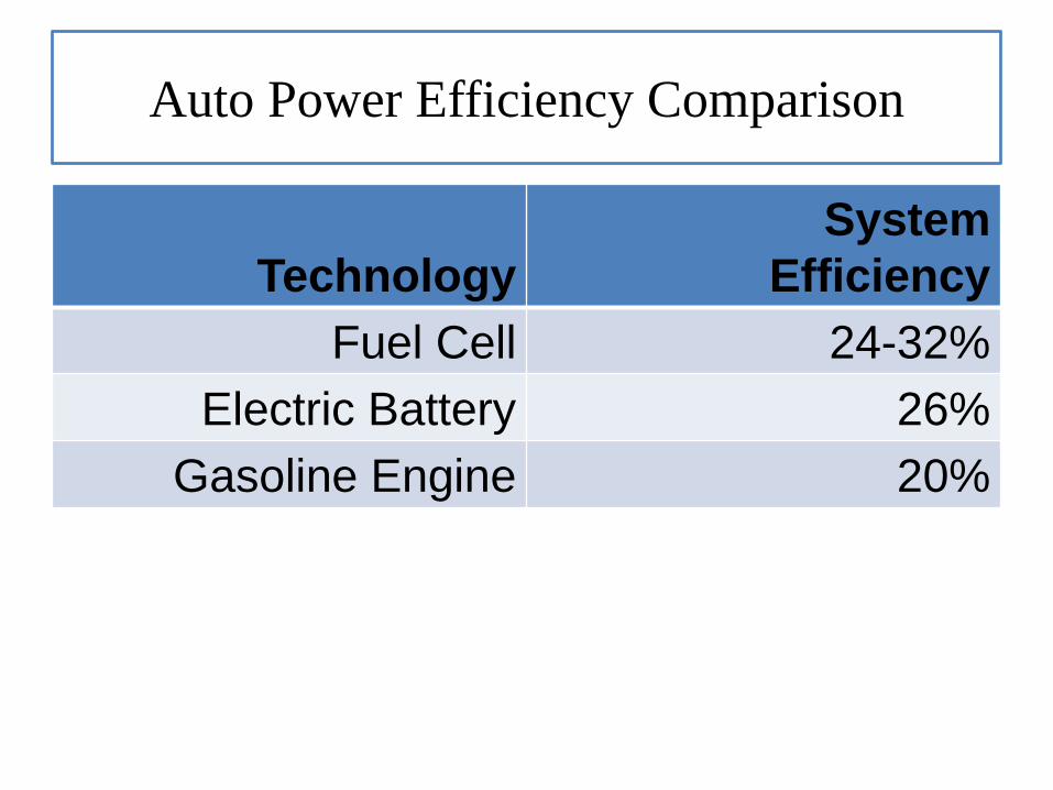
Auto Power Efficiency Comparison
Technology
System
Efficiency
Fuel Cell 24-32%
Electric Battery 26%
Gasoline Engine 20%


Fuel Cell In Use Stationary System

Fuel Cell In Use Transport

Fuel Cell in use
12 kW Space shuttle fuel
cell
Weight: 120 kg
Size: 36x38x114 cm
Contains 32 cells in
series
1.5 kW Apollo fuel cell
Apollo used two of these
units.
• Fuel cells provide us with various advantages over the existing combustion based technologies that we seek to replace because of various reasons, on of the major being that they run on fossil fuels which are non-renewable energy sources.
1. Environment friendly
2. Better efficiency (fuel cells produce electrical work from chemical energy directly than from shaft work i.e. turbines)
3. Renewable energy.
4. The maintenance of fuel cells is simple since there are few moving parts in the system.
5. Unlike batteries, fuel cells have no "memory effect" when they are getting refueled.
6. Operating times are much longer than with batteries, since doubling the operating time needs only doubling the amount of fuel and not the doubling of the capacity of the unit itself.
7. Since hydrogen can be produced anywhere where there is water and a source of power, generation of fuel can be distributed and does not have to be grid-dependent.
8. Most fuel cells operate silently, compared to internal combustion engines. They are therefore ideally suited for use within buildings such as hospitals.


• Fuel Cell Design• Designing fuel cells is a complex task and one which requires knowledge
of many scientific fields. Structurally the basic components of a fuel cell
are however listed below.
1. Fuel Cell Stack
2. Fuel Processor (The job of the fuel processor is to provide relatively pure hydrogen to a
fuel cell, using a fuel that is readily available or easily transportable.)
3. Current Convertor (DC to AC)
4. Other than that there are subsystems to control fuel cell humidity,
temperature, gas pressure and waste water.

Fuel Cell Stack A single fuel cell is only capable of producing about 1 volt, so
typical fuel cell designs link together many individual cells to form a
“stack” that produces a more useful voltage.

Fuel


• Basically mass is energy and to convert it into energy is possible except
that we have to provide the means to extract energy from the mass, it
could be electrons flowing in a circuit via an electrochemical process,
heat being released due to a chemical reaction or the break down of
mass which releases energy.
• During the working of the fuel cells, heat is evolved. This heat can be
utilized for the production of electricity. For this purpose many fuel cells
have what is called the heat recovery system.
• Heat Recovery System• Heat obtained as a by product can be used for further purposes such as
steam generation for further production of electricity through turbines.
• This basically increases the overall efficiency of the fuel cell i.e. if it’s
efficiency range is 50-60 % co generation of electricity could take the
efficiency up to 70-80 %.
• Let’s look at some diagrams for this purpose.s


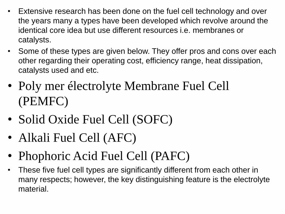
• Extensive research has been done on the fuel cell technology and over
the years many a types have been developed which revolve around the
identical core idea but use different resources i.e. membranes or
catalysts.
• Some of these types are given below. They offer pros and cons over each
other regarding their operating cost, efficiency range, heat dissipation,
catalysts used and etc.
• Poly mer électrolyte Membrane Fuel Cell
(PEMFC)
• Solid Oxide Fuel Cell (SOFC)
• Alkali Fuel Cell (AFC)
• Phophoric Acid Fuel Cell (PAFC)• These five fuel cell types are significantly different from each other in
many respects; however, the key distinguishing feature is the electrolyte
material.


Solid Oxide Fuel Cell
(SOFC)

• High temperature fuel cells (HTFCs), such as solid oxide fuel cells and
molten carbonate fuel cells are especially well suited for hybrid operation.
• The high operating temperature of these fuel cell systems allows
integration with a gas turbine engine at a temperature that is mutually
beneficial.
• During operation of a SOFC two effects intervene reduce the electrical
power of the ideal cell. First is the ohmic resistance (which generates
heat)and the second one being the irreversible mixing of the gases which
causes the voltage to fall as progressively more fuel is used in the
reaction. Then losses in a SOFC appear as heat so it is necessary to
consider SOFC as a heat generator as well as an electricity source.
• Ultimately the heat output from the SOFC can be used to drive a heat
engine such as a piston engine or a gas turbine.
• Depending upon the design of the integrated hybrid system, waste heat
from the fuel cell could be converted in the gas turbine engine to
electricity or waste heat from the gas turbine could be put to good use
preheating the reactants for the fuel cell or providing heat for fuel
processing.

Normal Fuel Cell Operation

Hybrid Design Concepts (Co Word “Synergy”) The basic design goal of a hybrid system is to integrate two or more energy
conversion devices—or two or more fuels for the same device—into a singlesystem that provides benefits in terms of fuel flexibility, efficiency, availability,economics or sustainability that either of the devices alone could notprovide.
In the particular case of a gas turbine fuel cell hybrid system the primarydesign concepts are as follows:
(1) convert most of the fuel by electro-oxidation in the fuel cell leading to lowemissions of criteria pollutants and relatively high fuel-to-electricityconversion efficiency,
(2) use fuel cell heat and turbine exhaust heat elsewhere in the system (e.g.,fuel processing, reactant preheating, provide compression power) in amanner in which overall efficiency is enhanced,
(3) use the high pressure produced by the gas turbine in a manner thatimproves fuel cell output and efficiency (if possible), and
(4) use the separated fuel and oxidant streams of the fuel cell to enhanceother features (e.g., CO 2 sequestration, fuel production) of the hybrid cycle(if possible).

• Solid oxide fuel cells (SOFCs) use a hard, non-porous ceramic compound
as the electrolyte.
• Because the electrolyte is a solid, the cells do not have to be constructed
in the plate-like configuration typical of other fuel cell types.
• Typically the anode of an SOFC is nickel zirconica (Ni-ZrO 2 ) and the
cathode is strontium-doped lanthanum manganite (Sr-doped LaMnO 3 ).
5
• SOFCs are expected to be around 50%–60% efficient at converting fuel
to electricity.
• Solid oxide fuel cells operate at very high temperatures—around 1,000°C
(1,830°F). High-temperature operation removes the need for precious-
metal catalyst, thereby reducing cost.
• SOFCs are also the most sulfur-resistant fuel cell type; they can tolerate
several orders of magnitude more of sulfur than other cell types. In
addition, they are not poisoned by carbon monoxide (CO).
• Applications designed to capture and utilize the system's waste heat (co-
generation), overall fuel use efficiencies could top 80%–85%.


Hybrid Operation Of
(SOFC)

• High temperature fuel cells (HTFCs), such as solid oxide fuel cells and
molten carbonate fuel cells are especially well suited for hybrid operation.
• The high operating temperature of these fuel cell systems allows
integration with a gas turbine engine at a temperature that is mutually
beneficial.
• During operation of a SOFC two effects intervene reduce the electrical
power of the ideal cell. First is the ohmic resistance (which generates
heat)and the second one being the irreversible mixing of the gases which
causes the voltage to fall as progressively more fuel is used in the
reaction. Then losses in a SOFC appear as heat so it is necessary to
consider SOFC as a heat generator as well as an electricity source.
• Ultimately the heat output from the SOFC can be used to drive a heat
engine such as a piston engine or a gas turbine.
• Depending upon the design of the integrated hybrid system, waste heat
from the fuel cell could be converted in the gas turbine engine to
electricity or waste heat from the gas turbine could be put to good use
preheating the reactants for the fuel cell or providing heat for fuel
processing.


• References • A paper by Professor Jack Brouwer, Ph.D. Associate Director,
University of California.
• Videos sourced from internet.


