Fuel Cell Impedance Measurement System KFM2150SYSTEM … · This chapter describes maintenance of...
206
OPERATION MANUAL Fuel Cell Impedance Measurement System Part No. Z1-003-892, IB011533 May. 2016 KFM2150SYSTEM 165-01A 660-01A 1320-02A 1980-03A 2640-04A 3300-05A 1000-01 3000-02 5000-03 7000-04 9000-05
Transcript of Fuel Cell Impedance Measurement System KFM2150SYSTEM … · This chapter describes maintenance of...

OPERATION MANUAL Fuel Cell Impedance Measurement System
Part No. Z1-003-892, IB011533
May. 2016
KFM2150SYSTEM 165-01A
660-01A 1320-02A 1980-03A 2640-04A 3300-05A 1000-01
3000-02 5000-03 7000-04 9000-05

Use of Operation ManualPlease read through and understand this Operation Manual before operating the product. After reading,always keep the manual nearby so that you may refer to it as needed. When moving the product to anotherlocation, be sure to bring the manual as well.If you find any misplaced or missing pages in this manual, they will be replaced. If the manual gets lost orsoiled, a new copy can be provided for a fee. In either case, please contact Kikusui distributor/agent, andprovide the “Kikusui Part No.” given on the cover.This manual has been prepared with the utmost care; however, if you have any questions, or note any errorsor omissions, please contact Kikusui distributor/agent.
Reproduction and reprinting of this operation manual, in whole or in part, without written permission isprohibited.Both unit specifications and manual contents are subject to change without notice.
Copyright© 2006 Kikusui Electronics Corporation

KFM2150 SYSTEM 1
Safety SymbolsFor the safe use and safe maintenance of this product, the following symbols areused throughout this manual and on the product. Note the meaning of each of thesymbols to ensure safe use of the product. (Not all symbols may be used.)
or
Indicates that a high voltage (over 1000 V) is used here.Carelessly touching the part may cause fatal electric shock. If physicalcontact is required by your work, start work only after you make surethat no voltage is output here.
DANGER Indicates an imminently hazardous situation which, if ignored, will resultin death or serious injury.
WARNING
Indicates a potentially hazardous situation which, if ignored, could resultin death or serious injury.
CAUTION
Indicates a potentially hazardous situation which, if ignored, may resultin damage to the product and other property.
Shows that the act indicated is prohibited.
Indicates a general danger, warning, or caution.When this symbol is marked on the product, see the relevant sections inthis manual.
Protective conductor terminal.
Chassis (frame) terminal.
On (supply)
Off (supply)
In position of a bi-stable push control
Out position of a bi-stable push control
!

2 KFM2150 SYSTEM
Safety PrecautionsThe following safety precautions must be observed to avoid fire hazards, electricshock, accidents, and other failures. Keep them in mind and make sure to observethem.
Using the product in a manner that is not specified in this manual may impair theprotection functions provided by the product.
Users • This product must be used only by qualified personnel who understandthe contents of this operation manual.
• If unqualified personnel is to use the product, be sure the product ishandled under the supervision of qualified personnel (those who haveelectrical knowledge). This is to prevent the possibility of personal injury.
Purpose of use
• Never use the product for purposes other than the product's intendeduse.
• This product is not designed or manufactured for general home orconsumer use.
Input power
• Use the product within the rated input power voltage range.
• For applying power, use the power cord provided. For details, see therespective page in the operation manual.
• This product is designed as an equipment of IEC Overvoltage CategoryII (energy-consuming equipment supplied from the fixed installation).
Cover • Some parts inside the product may cause physical hazards. Do notremove the external cover.
Grounding • This product is an IEC Safety Class I equipment (equipment with aprotective conductor terminal). To prevent the possibility of electricshock, be sure to connect the protective conductor terminal of theproduct to electrical ground (safety ground).
!
Operation
Manual
LineVoltage
G N L

KFM2150 SYSTEM 3
Installation • This product is designed for safe indoor use. Be sure to use it indoors.
• When installing this product, be sure to observe the description insection 1.2, “Precautions Concerning Installation Location” in thismanual.
Relocation • Turn off the POWER switch, and disconnect all cables before relocatingthe product.
• When moving the product, have more than one person carry it.
• When relocating the product, be sure to include the manual.
Operation • Before using the product, be sure to check the input power voltage andthat there is no abnormality in the appearance of the power cord. Besure to remove the power plug from the outlet before checking it.
• If a malfunction or abnormality is detected on the product, stop using itimmediately, and remove the power plug from the outlet. Make sure theproduct is not used until it is completely repaired.
• Use cables or wires with sufficiently large current capacity for outputwires and load cables.
• Do not disassemble or modify the product. If you need to modify theproduct, contact your Kikusui distributor/agent.
Maintenance and inspection
• To prevent the possibility of electric shock, make sure to unplug thepower plug before carrying out maintenance or inspection.
• Do not remove the external cover during maintenance or inspection.
• To maintain the performance and safe operation of the product, it isrecommended that periodic maintenance, inspection, cleaning, andcalibration be performed.
Service • Kikusui service engineers will perform internal service on the product. Ifthe product needs adjustment or repairs, contact your Kikusuidistributor/agent.
Check?

4 KFM2150 SYSTEM
How to Read This Manual
Preface
Thank you for purchasing the KFM2150 SYSTEM Fuel Cell ImpedanceMeasurement System.
This manual is intended for first-time users of the KFM2150. It gives an overview ofthe fuel cell impedance measurement system and describes installation proceduresand preparation.
Read this manual thoroughly to use the functions of the KFM2150 effectively. Youcan also review this manual when you are confused about an operation or when aproblem occurs.
For details on the individual instruments making up the impedance measurementsystem such as the PLZ-4W Series Electronic Load Units and other externalequipment, see the respective operation manuals.
How to read this manual
This manual is designed to be read from beginning to end. We recommend that youread the manual thoroughly from the beginning before using the KFM2150 for thefirst time.
Related manuals
The products listed below are used in the fuel cell impedance measurement system.For details, see the respective operation manual.
• KFM2151 FC Scanner (option)
• Application Software
• Communication Interface Manual (FC Impedance Meter)
Electronic manual provided with the application software
Intended readers of this manual
This manual is intended for operators that control and use the impedancemeasurement system or persons teaching other users on how to operate the system.
It assumes that the reader has knowledge about fuel cells and electrical aspects ofimpedance measurement. Information on SCPI commands is provided with thepremise that the reader has sufficient knowledge about controlling instruments usinga personal computer.

KFM2150 SYSTEM 5
1
2
3
4
5
6
7
App
Structure of the Manual
This manual consists of the Installation Part and Operation Part.
Installation PartDescribes the installation of the KFM2150.
Chapter 1 Description of the InstallationThis chapter describes a general description of the installation. It also introduces thefeatures of the product and indicates the firmware version of the product to whichthis manual applies.
Chapter 2 Installation of the Bench Top TypeThis chapter describes the procedures from unpacking to installation of the benchtop type.
Chapter 3 Installation of the Rack Mount TypeThis chapter describes the procedures from unpacking to installation of the rackmount type.
Operation PartDescribes the operations of the impedance meter.
Chapter 4 Basic OperationsThis chapter describes basic operations and how to use the various functions.
Chapter 5 Impedance MeasurementThis chapter describes how to use the impedance measurement system.
Chapter 6 MaintenanceThis chapter describes maintenance of the KFM2150 including cleaning, inspecting,calibrating, and troubleshooting.
Chapter 7 SpecificationsThis chapter describes the specifications of the KFM2150 system.
AppendixThe appendix describes an overview of the fuel cell and evaluation system and thebasics of the electronic load unit and wiring.

6 KFM2150 SYSTEM
Notations used in the manual
• The “KFM2150 FC Impedance Meter” is also simply referred to as “KFM2150”in this manual.
• The “PLZ-4W Series Electronic Load Unit” is also referred to as the “PLZ-4W”or the “PLZ-4W Series” in this manual.
• The word computer, controller, and PC used in the text are general terms thatdescribe personal computers and workstations.
• The following markings are used in the explanations in the text.
Indicates a potentially hazardous situation which, if ignored, could result indeath or serious injury.
Indicates a potentially hazardous situation which, if ignored, may result indamage to the product and other property.
Indicates information that you should know or convenient tips.
Explanation of terminology or operation principle.
Indicates reference to detailed information.
>Indicates menu settings that you select. Menu items to the right of the greater-than sign is are submenus.
SHIFT+key name (marked in blue)Indicates an operation in which a key marked in blue is pressed while holdingdown the SHIFT key.
WARNING
CAUTION
DESCRIPTION
See

KFM2150 SYSTEM 7
1
2
3
4
5
6
7
App
Contents
Safety Symbols - - - - - - - - - - - - - - - - - - - - - - - - - - - - - - - - - - - - - - - - - - - - - - - - - 1
Safety Precautions - - - - - - - - - - - - - - - - - - - - - - - - - - - - - - - - - - - - - - - - - - - - - - - 2
How to Read This Manual - - - - - - - - - - - - - - - - - - - - - - - - - - - - - - - - - - - - - - - - - 4Structure of the Manual - - - - - - - - - - - - - - - - - - - - - - - - - - - - - - - - - - - - - - - - - - - 5
Function Index - - - - - - - - - - - - - - - - - - - - - - - - - - - - - - - - - - - - - - - - - - - - - - - - 11
Front panel of the bench top type - - - - - - - - - - - - - - - - - - - - - - - - - - - - - - - - - - - 13
Rear panel of the bench top types - - - - - - - - - - - - - - - - - - - - - - - - - - - - - - - - - - 16
Rear panel of the bench top type - - - - - - - - - - - - - - - - - - - - - - - - - - - - - - - - - - - 17
Front panel of the rack mount type - - - - - - - - - - - - - - - - - - - - - - - - - - - - - - - - - - 18
Front panel of the rack mount type - - - - - - - - - - - - - - - - - - - - - - - - - - - - - - - - - - 19
Rear panel of the rack mount type - - - - - - - - - - - - - - - - - - - - - - - - - - - - - - - - - - 20
KFM2151 FC Scanner (Option) - - - - - - - - - - - - - - - - - - - - - - - - - - - - - - - - - - - - 21
FC Impedance Mater KFM2150 panel- - - - - - - - - - - - - - - - - - - - - - - - - - - - - - - - 22
KFM2150 rear panel - - - - - - - - - - - - - - - - - - - - - - - - - - - - - - - - - - - - - - - - - - - - 24
Installation Part
Chapter 1 Description of the Installation1.1 Firmware Version- - - - - - - - - - - - - - - - - - - - - - - - - - - - - - - - - - - - - - - - - - 1-2
1.1.1 Firmware Version of the Product to Which This Manual Applies - - - - 1-2
1.1.2 Firmware Version of the PLZ-4W Series Electronic Load Unit - - - - - - 1-2
1.2 Precautions Concerning Installation Location - - - - - - - - - - - - - - - - - - - - - - 1-3
1.3 Precautions to Be Taken When Moving the Product - - - - - - - - - - - - - - - - - 1-4
1.4 Parts That You Prepare - - - - - - - - - - - - - - - - - - - - - - - - - - - - - - - - - - - - - 1-5
1.5 Product Overview - - - - - - - - - - - - - - - - - - - - - - - - - - - - - - - - - - - - - - - - - 1-6
1.5.1 Measurement System Types - - - - - - - - - - - - - - - - - - - - - - - - - - - - - 1-7
1.6 Features - - - - - - - - - - - - - - - - - - - - - - - - - - - - - - - - - - - - - - - - - - - - - - - 1-10
1.7 Options- - - - - - - - - - - - - - - - - - - - - - - - - - - - - - - - - - - - - - - - - - - - - - - - 1-11
1.8 Application Software - - - - - - - - - - - - - - - - - - - - - - - - - - - - - - - - - - - - - - 1-12
Chapter 2 Installation of the Bench Top Type2.1 Checking the Package Contents - - - - - - - - - - - - - - - - - - - - - - - - - - - - - - - 2-2
2.1.1 System Component Instruments - - - - - - - - - - - - - - - - - - - - - - - - - - 2-2
2.1.2 Accessories by Model - - - - - - - - - - - - - - - - - - - - - - - - - - - - - - - - - - 2-3
2.1.3 Wiring of the Bench Top Type - - - - - - - - - - - - - - - - - - - - - - - - - - - - 2-4
2.2 Load Wires - - - - - - - - - - - - - - - - - - - - - - - - - - - - - - - - - - - - - - - - - - - - - - 2-6
2.2.1 Wiring the Load Input Terminal - - - - - - - - - - - - - - - - - - - - - - - - - - - 2-7
2.2.2 Relationship between the Minimum Input OperatingVoltage and Impedance Measurement - - - - - - - - - - - - - - - - - - - - - - 2-9
2.2.3 PLZ4W Remote Sensing Function - - - - - - - - - - - - - - - - - - - - - - - - 2-10
2.3 Sensing Wires - - - - - - - - - - - - - - - - - - - - - - - - - - - - - - - - - - - - - - - - - - - 2-12

8 KFM2150 SYSTEM
2.4 Sensing Wires of the FC Scanner (Option) - - - - - - - - - - - - - - - - - - - - - - - 2-14
2.5 Connecting the KFM2150 and the PLZ-4W Series- - - - - - - - - - - - - - - - - - 2-16
2.6 Connecting the KFM2150 and KFM2151 (option) - - - - - - - - - - - - - - - - - - 2-18
2.7 PC Control Wire - - - - - - - - - - - - - - - - - - - - - - - - - - - - - - - - - - - - - - - - - - 2-20
2.8 Connecting the Power Cord and Grounding (Earth) - - - - - - - - - - - - - - - - - 2-22
Chapter 3 Installation of the Rack Mount Type3.1 Checking the Package Contents - - - - - - - - - - - - - - - - - - - - - - - - - - - - - - - 3-2
3.1.1 System Configuration of the rack mount type - - - - - - - - - - - - - - - - - - 3-2
3.1.2 Accessories by Model - - - - - - - - - - - - - - - - - - - - - - - - - - - - - - - - - - 3-3
3.1.3 Wiring of the Rack Mount Type- - - - - - - - - - - - - - - - - - - - - - - - - - - - 3-4
3.2 Load Wires - - - - - - - - - - - - - - - - - - - - - - - - - - - - - - - - - - - - - - - - - - - - - - 3-6
3.2.1 Wiring the Load Input Terminal- - - - - - - - - - - - - - - - - - - - - - - - - - - - 3-6
3.2.2 Relationship between the Minimum Input OperatingVoltage and Impedance Measurement - - - - - - - - - - - - - - - - - - - - - - 3-8
3.2.3 PLZ4W Remote Sensing Function - - - - - - - - - - - - - - - - - - - - - - - - - 3-8
3.3 Sensing Wires - - - - - - - - - - - - - - - - - - - - - - - - - - - - - - - - - - - - - - - - - - - 3-10
3.4 Connecting the FC Scanner (Option) - - - - - - - - - - - - - - - - - - - - - - - - - - - 3-12
3.5 PC Control Wire - - - - - - - - - - - - - - - - - - - - - - - - - - - - - - - - - - - - - - - - - - 3-14
3.6 Connecting the Power Cable and Grounding (Earth) - - - - - - - - - - - - - - - - 3-16
Operation Part
Chapter 4 Basic Operation4.1 Turning the System On - - - - - - - - - - - - - - - - - - - - - - - - - - - - - - - - - - - - - - 4-2
4.1.1 Bench Top Type - - - - - - - - - - - - - - - - - - - - - - - - - - - - - - - - - - - - - - 4-2
4.1.2 Rack Mount Type - - - - - - - - - - - - - - - - - - - - - - - - - - - - - - - - - - - - - 4-6
4.2 Setting the Impedance Measurement System - - - - - - - - - - - - - - - - - - - - - - 4-7
4.3 Protection Function- - - - - - - - - - - - - - - - - - - - - - - - - - - - - - - - - - - - - - - - - 4-8
4.3.1 Types of protection functions - - - - - - - - - - - - - - - - - - - - - - - - - - - - - 4-8
4.3.2 Transition from CC Mode to CV Mode- - - - - - - - - - - - - - - - - - - - - - 4-10
4.3.3 Details of the Undervoltage Protection (PLZ4W UVP)- - - - - - - - - - - 4-10
4.3.4 Details of the Voltage Sensing Undervoltage Protection (SENSE UVP) 4-11
4.3.5 Setting the Protection Function- - - - - - - - - - - - - - - - - - - - - - - - - - - 4-12
4.3.6 Alarm Occurrence and Release - - - - - - - - - - - - - - - - - - - - - - - - - - 4-12
4.4 Memory Function - - - - - - - - - - - - - - - - - - - - - - - - - - - - - - - - - - - - - - - - - 4-14
4.5 Other Settings - - - - - - - - - - - - - - - - - - - - - - - - - - - - - - - - - - - - - - - - - - - 4-16
4.6 Setting the Remote Control - - - - - - - - - - - - - - - - - - - - - - - - - - - - - - - - - - 4-18
4.6.1 GPIB Interface - - - - - - - - - - - - - - - - - - - - - - - - - - - - - - - - - - - - - - 4-18
4.6.2 RS232C Interface - - - - - - - - - - - - - - - - - - - - - - - - - - - - - - - - - - - - 4-20
4.6.3 USB Interface - - - - - - - - - - - - - - - - - - - - - - - - - - - - - - - - - - - - - - - 4-22
4.6.4 Command Details - - - - - - - - - - - - - - - - - - - - - - - - - - - - - - - - - - - - 4-23
4.7 Installing the Application Software (FCTester) - - - - - - - - - - - - - - - - - - - - - 4-24

KFM2150 SYSTEM 9
1
2
3
4
5
6
7
App
4.8 Details on Menu Setup - - - - - - - - - - - - - - - - - - - - - - - - - - - - - - - - - - - - - 4-26
Chapter 5 Impedance Measurement5.1 Impedance Measurement Basics - - - - - - - - - - - - - - - - - - - - - - - - - - - - - - 5-2
5.1.1 Running the Load Current - - - - - - - - - - - - - - - - - - - - - - - - - - - - - - - 5-2
5.1.2 Operating Status of the Fuel Cell and Impedance Measurement - - - - 5-2
5.1.3 Impedance Measurement System - - - - - - - - - - - - - - - - - - - - - - - - - 5-3
5.2 Setting the Load Current - - - - - - - - - - - - - - - - - - - - - - - - - - - - - - - - - - - - 5-4
5.2.1 Setting the Current Range- - - - - - - - - - - - - - - - - - - - - - - - - - - - - - - 5-4
5.2.2 Setting the Current of CC Mode - - - - - - - - - - - - - - - - - - - - - - - - - - - 5-5
5.2.3 Setting the CV mode transition voltage - - - - - - - - - - - - - - - - - - - - - - 5-5
5.3 Turning the Load On/Off (Turning the Load Current On/Off)- - - - - - - - - - - - 5-6
5.3.1 Load On and Soft Start Rising Edge- - - - - - - - - - - - - - - - - - - - - - - - 5-8
5.3.2 Load Off and Soft Start Falling Edge - - - - - - - - - - - - - - - - - - - - - - - 5-9
5.3.3 Protection Function and Load Off- - - - - - - - - - - - - - - - - - - - - - - - - - 5-9
5.4 AC Impedance Method- - - - - - - - - - - - - - - - - - - - - - - - - - - - - - - - - - - - - 5-10
5.4.1 Selecting the measurement method - - - - - - - - - - - - - - - - - - - - - - - 5-11
5.4.2 Setting the measuring frequency - - - - - - - - - - - - - - - - - - - - - - - - - 5-11
5.4.3 Setting the Load Current - - - - - - - - - - - - - - - - - - - - - - - - - - - - - - - 5-12
5.4.4 Setting the Measuring AC Current - - - - - - - - - - - - - - - - - - - - - - - - 5-12
5.5 Current Interrupt Method - - - - - - - - - - - - - - - - - - - - - - - - - - - - - - - - - - - 5-14
5.5.1 Selecting the Measurement Method - - - - - - - - - - - - - - - - - - - - - - - 5-15
5.5.2 Setting the Pulse Width- - - - - - - - - - - - - - - - - - - - - - - - - - - - - - - - 5-15
5.5.3 Setting the Pulse Depth - - - - - - - - - - - - - - - - - - - - - - - - - - - - - - - 5-15
5.5.4 Setting the Pulse Transition Time- - - - - - - - - - - - - - - - - - - - - - - - - 5-16
5.5.5 Setting the Sampling- - - - - - - - - - - - - - - - - - - - - - - - - - - - - - - - - - 5-16
5.5.6 Setting the Load Current - - - - - - - - - - - - - - - - - - - - - - - - - - - - - - - 5-17
5.6 Setting the Average Count - - - - - - - - - - - - - - - - - - - - - - - - - - - - - - - - - - 5-18
5.7 Displaying the Measured Results - - - - - - - - - - - - - - - - - - - - - - - - - - - - - 5-19
5.8 Short-Circuit Correction Function - - - - - - - - - - - - - - - - - - - - - - - - - - - - - 5-21
5.9 Judgement Function - - - - - - - - - - - - - - - - - - - - - - - - - - - - - - - - - - - - - - 5-24
Chapter 6 Maintenance6.1 Cleaning and Inspection - - - - - - - - - - - - - - - - - - - - - - - - - - - - - - - - - - - - - 6-2
6.2 Calibration- - - - - - - - - - - - - - - - - - - - - - - - - - - - - - - - - - - - - - - - - - - - - - - 6-3
6.3 Troubleshooting- - - - - - - - - - - - - - - - - - - - - - - - - - - - - - - - - - - - - - - - - - - 6-3
Chapter 7 Specifications7.1 Basic Performance- - - - - - - - - - - - - - - - - - - - - - - - - - - - - - - - - - - - - - - - - 7-2
7.2 Impedance measurement - - - - - - - - - - - - - - - - - - - - - - - - - - - - - - - - - - - - 7-6
7.3 Functions and General Specifications - - - - - - - - - - - - - - - - - - - - - - - - - - 7-14
7.4 Outline Drawing- - - - - - - - - - - - - - - - - - - - - - - - - - - - - - - - - - - - - - - - - - 7-18
AppendixA.1 Connection to External Devices - - - - - - - - - - - - - - - - - - - - - - - - - - - - - - - A-2

10 KFM2150 SYSTEM
A.1.1 Controlling an External Load Unit - - - - - - - - - - - - - - - - - - - - - - - - - - A-2
A.1.2 Using Channel 2 of the CURRENT SENSING Terminal - - - - - - - - - - A-4
A.1.3 J1 Connector - - - - - - - - - - - - - - - - - - - - - - - - - - - - - - - - - - - - - - - - A-4
A.2 Factory Default Settings - - - - - - - - - - - - - - - - - - - - - - - - - - - - - - - - - - - - - A-6
A.3 Overview of the Fuel Cell and Evaluation System - - - - - - - - - - - - - - - - - - - A-7
A.3.1 Fuel Cell- - - - - - - - - - - - - - - - - - - - - - - - - - - - - - - - - - - - - - - - - - - - A-7
A.3.2 Installation Environment- - - - - - - - - - - - - - - - - - - - - - - - - - - - - - - - - A-7
A.3.3 Precautions Concerning Installation - - - - - - - - - - - - - - - - - - - - - - - - A-8
A.4 Load Wires - - - - - - - - - - - - - - - - - - - - - - - - - - - - - - - - - - - - - - - - - - - - - A-10
A.4.1 Wire Structure- - - - - - - - - - - - - - - - - - - - - - - - - - - - - - - - - - - - - - - A-10
A.4.2 Current Capacity - - - - - - - - - - - - - - - - - - - - - - - - - - - - - - - - - - - - - A-10
A.5 Wiring - - - - - - - - - - - - - - - - - - - - - - - - - - - - - - - - - - - - - - - - - - - - - - - - - A-11
A.5.1 Connecting the Wires - - - - - - - - - - - - - - - - - - - - - - - - - - - - - - - - - A-11
A.5.2 Wiring the Load- - - - - - - - - - - - - - - - - - - - - - - - - - - - - - - - - - - - - - A-12
A.5.3 Wiring the sensing wires - - - - - - - - - - - - - - - - - - - - - - - - - - - - - - - A-14
A.6 What Is an Electronic Load Unit - - - - - - - - - - - - - - - - - - - - - - - - - - - - - - - A-16
A.6.1 Operation modes - - - - - - - - - - - - - - - - - - - - - - - - - - - - - - - - - - - - A-16
A.6.2 Operating Voltage Range- - - - - - - - - - - - - - - - - - - - - - - - - - - - - - - A-17
A.6.3 How to use CV mode and Remote Sensing - - - - - - - - - - - - - - - - - - A-18
A.7 I-V Characteristics Test- - - - - - - - - - - - - - - - - - - - - - - - - - - - - - - - - - - - - A-19
A.7.1 Voltage Drop Caused by the Wires - - - - - - - - - - - - - - - - - - - - - - - - A-19
A.7.2 Operating Voltage of the Electronic Load Unitand Voltage Drop in the Wire - - - - - - - - - - - - - - - - - - - - - - - - - - - - A-20
A.7.3 Summary of the Required Test Conditions- - - - - - - - - - - - - - - - - - - A-21
A.8 AC Impedance Characteristics Test - - - - - - - - - - - - - - - - - - - - - - - - - - - - A-22
A.8.1 Measurement Principles - - - - - - - - - - - - - - - - - - - - - - - - - - - - - - - A-22
A.8.2 Wire Inductance - - - - - - - - - - - - - - - - - - - - - - - - - - - - - - - - - - - - - A-23
A.8.3 Bottom Voltage - - - - - - - - - - - - - - - - - - - - - - - - - - - - - - - - - - - - - - A-24
A.9 Impedance Measurement Tests Using the Interrupt Method - - - - - - - - - - - A-28
A.9.1 Current Interrupt Method on the KFM2150- - - - - - - - - - - - - - - - - - - A-29
A.10 KFM2151 FC Scanner (Option) - - - - - - - - - - - - - - - - - - - - - - - - - - - - - - - A-34
A.10.1Overview of the Scanner System - - - - - - - - - - - - - - - - - - - - - - - - - A-34
A.10.2Notes on Setting the Scanner System- - - - - - - - - - - - - - - - - - - - - - A-35
A.10.3Voltmeter Display - - - - - - - - - - - - - - - - - - - - - - - - - - - - - - - - - - - - A-36
A.10.4Voltmeter Scanning Speed - - - - - - - - - - - - - - - - - - - - - - - - - - - - - A-37
A.10.5Impedance Display and Scanning- - - - - - - - - - - - - - - - - - - - - - - - - A-38
Index

KFM2150 SYSTEM 11
1
2
3
4
5
6
7
App
Function Index
Installation
Preparation
Situation HeadingPage
To check the wiring of the bench top type.2.5, “Connecting the KFM2150 and the PLZ-4W Series”
2-16
What are the types of system component instruments?1.5.1, “Measurement System Types”
1-7
What kind of load wires should be used?2.2, “Load Wires,” 3.2, “Load Wires”
2-63-6The fuel cell is located far away. What are the points to
be considered?
I am concerned about the power supply capacity. What is the maximum power consumption?
2.8, “Connecting the Power Cord and Grounding (Earth),”3.6, “Connecting the Power Cable and Grounding (Earth)”
2-223-18
Situation HeadingPage
How to turn on the power of each instruments in order when the system consists of great number of instruments.
4.1, “Turning the System On” 4-2
How to make an immediate measurements when the fuel cells are ready to be measured.
5.4, “AC Impedance Method,” 5.5, “Current Interrupt Method”
5-105-14
How to compensate the wiring impedance of the fuel cells.
5.8, “Short-Circuit Correction Function”
5-21
There are substantial problems with the fuel cells under the test. What are the concern that requires to pay attention?
4.3, “Protection Function” 4-8
How to save the measurement conditions to improve the efficiency of the measurement operation.
4.4, “Memory Function” 4-14
How to grasp the details of the component instruments of the impedance measurement system.
4.2, “Setting the Impedance Measurement System”
4-7
How to reset the KFM2150 system to factory default settings.
“Factory default settings” 4-17
It is possible to use a different external electronic load.A.1.1, “Controlling an External Load Unit”
A-2
Would like to turn on the warning light when the fuel cell voltage falls abnormally low. Does the KFM2150 provide control signal output?
4.3.6, “Alarm Occurrence and Release,” A.1.3, “J1 Connector”
4-12A-4
How to check the firmware version. “Checking the Firmware Version” 4-4
See
See

12 KFM2150 SYSTEM
Function Index
Start
During measurement
Situation HeadingPage
To start the measurement in sync with the startup time of the fuel cell. 5.3, “Turning the Load On/Off
(Turning the Load Current On/Off)”
5-6To control the load current in sync with the startup time of the fuel cell.
Situation HeadingPage
To measure the I-V characteristics. 5.2, “Setting the Load Current” 5-4
To measure using the AC impedance method. 5.4, “AC Impedance Method” 5-10
To measure using the current interrupt method. 5.5, “Current Interrupt Method” 5-14
To measure alternately using the AC impedance and current interrupt methods.
5.4, “AC Impedance Method,” 5.5, “Current Interrupt Method”
5-105-14
To set the display format of the measured results.5.7, “Displaying the Measured Results”
5-19
To compare the measured results under new operating conditions of the fuel cell to the measured results up to now. 5.9, “Judgement Function” 5-24To make GO/NOGO judgement on the measured results.
See
See

KFM2150 SYSTEM 13
1
2
3
4
5
6
7
App
Front panel of the bench top type
KFM2150 SYSTEM165-01A, 660-01A, and 1000-01
No. Name DescriptionPage
1 FC Impedance Meter KFM2150.2-2
2 Electronic Load Unit PLZ164WA, PLZ664WA, or PLZ1004W.
[1]
[2]
See

14 KFM2150 SYSTEM
Front panel of the bench top type
KFM2150 SYSTEM1320-02A
No. Name DescriptionPage
1 FC Impedance Meter KFM2150.
2-22 Electronic Load Unit PLZ664WA.
3 Electronic Load Unit PLZ664WA.
[1]
[2]
[3]
See

KFM2150 SYSTEM 15
1
2
3
4
5
6
7
App
Front panel of the bench top type
KFM2150 SYSTEM3000-02
No. Name DescriptionPage
1 FC Impedance Meter KFM2150.
2-22 Electronic Load Unit PLZ1004W.
3 Electronic Load Unit PLZ2004WB.
[1]
[2]
[3]
See

16 KFM2150 SYSTEM
Rear panel of the bench top types
KFM2150 FC Impedance Meter
See "KFM2150 rear panel" on page 24 for the part name and description.
[4] [5][1] [2]
[7][9][10][11][12]
[16][14] [15] [3]
[13] [8] [6]

KFM2150 SYSTEM 17
1
2
3
4
5
6
7
App
Rear panel of the bench top type
Electronic Load Unit
No. Name DescriptionPage
1 DC INPUT Load input terminal. 2-7
2 Remote sensing terminal PLZ4W remote sensing terminal. –
3 J1/J2J1: Connector for controlling from the KFM2150. J2: Connector for parallel operation.
2-164 EXT CONT
External control. Variable resistor for adjusting the full scale and offset.
5 GPIB GPIB cable connector.–
6 USB USB cable connector.
7 RS232C RS232C cable connector (for control from the KFM2150). 2-16
8 AC INPUT Connector for the power cord. 2-22
9 Serial number The serial number of the PLZ-4W. –
10 System serial numberThe serial number for the impedance measurement system.(a) Models other than PLZ164WA. (b) PLZ164WA.
2-2
11 Exhaust port Exhaust port for the cooling fan. –
[1]
[5]
[6]
[7]
[3] [10(a)]
[2]
[4]
[8] [9] [11]
[10(b)]
See

18 KFM2150 SYSTEM
Front panel of the rack mount type
KFM2150 SYSTEM1980-03A, 2640-04A, and 3300-05A
No. Name DescriptionPage
1 FC Impedance Meter KFM2150.
3-2
2 Electronic Load Unit PLZ664WA (KFM2150 SYSTEM1980-03A, 2640-04A, and 3300-05A).
3 Electronic Load Unit PLZ664WA (KFM2150 SYSTEM1980-03A, 2640-04A, and 3300-05A).
4 Electronic Load Unit PLZ664WA (KFM2150 SYSTEM1980-03A, 2640-04A, and 3300-05A).
5 Electronic Load Unit PLZ664WA (KFM2150 SYSTEM2640-04A and 3300-05A).
6 Electronic Load Unit PLZ664WA (KFM2150 SYSTEM3300-05A).
7 LINE AC line input indicator. –
8 POWER Power supply indication lamp.2-22
9 POWER switch POWER switch.
10 FC Scanner For the KFM2151 (option). 3-12
[1]
[10]
[2]
[3]
[4]
[5]
[6]
[8]
[9]
[7]
See

KFM2150 SYSTEM 19
1
2
3
4
5
6
7
App
Front panel of the rack mount type
KFM2150 SYSTEM5000-03, 7000-04, and 9000-05
No. Name DescriptionPage
1 FC Impedance Meter KFM2150.
3-2
2 Electronic Load Unit PLZ1004W (KFM2150 SYSTEM5000-03, 7000-04, and 9000-05).
3 Electronic Load Unit PLZ2004WB (KFM2150 SYSTEM5000-03, 7000-04, and 9000-05).
4 Electronic Load Unit PLZ2004WB (KFM2150 SYSTEM5000-03, 7000-04, and 9000-05).
5 Electronic Load Unit PLZ2004WB (KFM2150 SYSTEM7000-04 and 9000-05).
6 Electronic Load Unit PLZ2004WB (KFM2150 SYSTEM9000-05).
7 LINE AC line input indicator. –
8 POWER Power supply indication lamp.3-16
9 POWER switch POWER switch.
10 FC Scanner For the KFM2151 (option). 3-12
[1]
[10]
[2]
[3]
[4]
[5]
[6]
[8]
[9]
[7]
See

20 KFM2150 SYSTEM
Rear panel of the rack mount type
No. Name DescriptionPage
1 Load input terminal Links the DC INPUT of the installed electronic load units. 3-6
2 SENSING Voltage sensing terminal and PLZ4W remote sensing terminal. 3-10
3 Terminal cover Cover for the load input terminal and sensing terminal. –
4 LINE Illuminates when power is supplied to AC INPUT.3-16
5 AC INPUT Power input terminal block.
6 Scanner terminalPanel with a hole for wiring the SENSING terminal of the KFM2151 FC Scanner (option).
3-12
7 System serial number Serial number for the impedance measurement system. 3-2
[1]
[6]
[2]
[3]
[5]
[4]
[7]
See

KFM2150 SYSTEM 21
1
2
3
4
5
6
7
App
KFM2151 FC Scanner (Option)
Installation example to the KFM2150 SYSTEM165-01A, 660-01A, and 1000-01
It can also be installed to the rack mount type.
No. Name DescriptionPage
1 FC Scanner KFM2151 (option). 2-18
2 FC Impedance Meter KFM2150.2-2
3 Electronic Load Unit PLZ164WA, PLZ664WA, or PLZ1004W.
IMPIMP
VOLTVOLT VVCHCHOVPOVP
UVPUVP
RANGERANGE
TERMTERM
VOLT TERMCHANNEL
IMP VOLT SET
TERMREMOTE
LOCAL
CONFIG
CH1 CH2
CH17 CH18
CH3
CH19
CH4
CH20
CH5
CH21
CH6
CH22
CH7
CH23
CH8
CH24
CH9
CH25
CH10
CH26
CH11
CH27
CH12
CH28
CH13
CH29
CH14
CH30
CH15
CH31
CH16
CH32
SCAN
FC SCANNER
MON
SHIFT
ALL SCAN
ALL CLR
ALM CLR
KFM2151 [2]
[1]
[3]
See

22 KFM2150 SYSTEM
FC Impedance Mater KFM2150 panel
Front panel
Operation panel
Display
Display Operation panel
Stand
[1]
[2]
[3] [4]
[5] [6]
[8][7] [9]
[10]
[11]
[12][13][14][15][16][17][18]
[25]Measured values
[19]
[27]
AC impedance method: [20] [21]
Current interrupt method: [22] [23] [24]
[28] [29]
[31] [33]
[32] [34]
: AC impedance method
: Current interrupt method
[26]
[30] : Rising edge
: Falling edge
[35]c.c c.cc.vC.R

KFM2150 SYSTEM 23
1
2
3
4
5
6
7
App
No.Name
Description+SHIFT
1LOAD Load on/off switch.
5-6SOFT START Load on (soft start rising)/load off (soft start falling) switch.
2 DC Load current set key. 5-4
3 PROTECT Protection function set key. 4-8
4 METHODKey for switching between AC impedance method and current interrupt
method .
5-105-14
5 FREQ Measuring frequency set key (AC impedance method). 5-11
6 ACKey for setting the measuring AC current and switching the unit between % and A (AC impedance method).
5-12
7 WIDTH Pulse width set key of the interrupt current (current interrupt method). 5-15
8DEPTH Key for setting the pulse depth of the interrupt current and switching the unit
between % and A (current interrupt method).5-15
9TRNSN Pulse transition time set key of the interrupt current (current interrupt
method).5-16
10 AVE Average count set key. 5-18
11 CURSOR Up, down, left, and right keys. –
12Rotary knob Knob for changing values and settings. –
contrast Display contrast adjustment knob. 4-16
13MENU Menu key. 4-26
INIT Initialize (factory default) key. 4-17
14RECALL Memory recall key.
4-14STORE Memory storage key (selectable memories are A, B, and C).
15 ENTER Key for applying settings and releasing the alarm. 4-12
16 SHIFT Shift key. Accepts commands marked in blue on the panel. 6
17LOCAL Local mode switch key. 4-17
LOCK Key for locking/unlocking the panel operation. 4-16
18 VIEW Setup window display key. 5-19
19 DC Displays the load current. 5-4
20 FREQ Displays the measuring frequency (AC impedance method). 5-11
21 AC Displays the measuring current (AC impedance method). 5-12
22 PW Displays the interrupt current pulse width (current interrupt method). 5-15
23 PD Displays the interrupt current pulse depth (current interrupt method). 5-15
24 PT Displays the interrupt current pulse transition time (current interrupt method). 5-16
25 Measured value Displays the measured value. 5-19
26 METHOD Displays the selected measurement method (AC impedance or current interruption).
5-105-14
27 AVE Displays the average count. 5-18
28 MEM A/B/C Displays the stored memory or recalled memory. 4-14
29 LOCK Displays the lock status. 4-16
30SOFT START
Displays the soft start rise time or fall time [hour:minute:second]. 5-7
31 Scanner Displayed for a scanner system in combination with the KFM2151. 5-20
See

24 KFM2150 SYSTEM
KFM2150 rear panel
32 SC Display when the short-circuit correction function is enabled. 5-21
33 GO/NOGO Displays the judgement result (when the judge function is enabled). 5-24
34Alarm Displayed when a protection function is activated (OPP/UVP/OVP/REV/OHP/
EXT).4-12
35CC, CV, CR PLZ-4W operation mode display (CC: Constant Current. CV: Constant
Voltage. CR: Constant Resistance)5-5
No.Name
Description+SHIFT
See
[4] [5][1] [2]
[6][8][9][10][11]
[15][13] [14] [3]
[12] [7]
No. Name Description
1 CURRENT SENSING 2 Current sensing input channel 2. A-4
2 VOLTAGE SENSING 2Voltage sensing input channel 2.DC input voltage range: 0 V to 150 V. Input impedance: approx. 1 MΩ . 2-12
3-10A-353 VOLTAGE SENSING 1
Voltage sensing input channel 1.DC input voltage range: 0 V to 150 V. Input impedance: approx. 1 MΩ .
4 AC INPUT Connector for the power cord. 2-22
5 POWERPOWER switch.
Press the ( ) side to turn the power on and the ( ) to turn the power off.2-224-2
6 System serial numberThe serial number for the impedance measurement system. 2-2
4-4
7 Serial number The serial number of the KFM2150. –
8 GPIB GPIB cable connector for remote control.2-204-189 USB USB cable connector for remote control.
10 RS232C RS232C cable connector for remote control.
11 OPTION Terminal for functional expansion. –
12 RS232C (PLZ-4W) Connector for controlling the PLZ-4W Series Electronic Load Unit. 2-16
13 Cord holder Holder for winding the power cord for storage. –
14 J1 (PLZ-4W)Output connector for the PLZ-4W Series and KFM2150 status signals and other signals. 2-16
15 J2 (PLZ-4W) Connector for controlling the PLZ-4W Series Electronic Load Unit.
16 CONTROL TERMINAL Signal terminal for the external electronic load unit. A-3
See

OPERATION MANUALImpedance Measurement System
KFM2150SYSTEM
Inst
alla
tio
nP
art
Installation Part


Description of theInstallation
This chapter describes a general description of the installation.It also introduces the features of the product and indicates thefirmware version of the product to which this manual applies.

1-2 KFM2150 SYSTEM
Installation Part
1.1 Firmware Version
Check the firmware version.
1.1.1 Firmware Version of the Product to Which This ManualApplies
This manual applies to KFM2150 systems with firmware version 1.1X.
When making an inquiry about the product, please provide us with the followinginformation.
• System model
The system model is indicated on the front cover of this manual and at thebottom of the rear panel of the product. It is indicated on each product on thebench top type and on the rack on the rack mount type.
• Firmware version
p.4-2The firmware version is shown on the KFM2150 display. For the procedure toview the firmware version, “see 4.1, “Turning the System On.”
• Serial number
The serial number is indicated at the bottom of the rear panel along with thesystem model. It is indicated on each product on the bench top type and on therack on the rack mount type.
• System serial number
The system serial number is a unique number of each system. Systems cannot becomposed using products with different system serial numbers. The system serialnumber is indicated on the rear panel of the product separately from the serialnumber of the product.
1.1.2 Firmware Version of the PLZ-4W Series Electronic Load Unit
This system and the accompanying application software apply to the PLZ-4WSeries Electronic Load Unit with firmware version 1.18 or higher.
When making an inquiry about the PLZ-4W Series Electronic Load Unit, pleaseprovide us with the following information.
• Model
• Firmware version
The firmware version is shown on the display of the PLZ-4W Series ElectronicLoad Unit. For the procedure to view the firmware version, see the operation manualof the PLZ-4W Series Electronic Load Unit (indicated as the ROM version).
• The serial number will be assigned specifically to the PLZ-4W unit when it isshipped as a part of the system configuration.Therefore, any other same model ofPLZ unit can not be substitute as a replacement purpose.
See

KFM2150 SYSTEM 1-3
Installation Part
Des
crip
tio
n o
f th
e In
stal
lati
on
11.2 Precautions Concerning Installation Location
Install the product indoors under the following conditions.
Do not use the product in a flammable atmosphere.
To prevent explosion or fire, do not use the product near alcohol, thinner or othercombustible materials, or in an atmosphere containing such vapors.
Avoid locations where the product is exposed to high temperature ordirect sunlight.
Do not install the product near a heater or in areas subject to drastic temperature changes.
Operating temperature range:0 °C to +40 °C
Storage temperature range: -20 °C to +70 °C
Avoid humid environments.
Do not install the product in high-humidity locations near a boiler, humidifier, orwater supply.
Operating humidity range: 20 %rh to 85 %rh (no condensation)
Storage humidity range: 0 to 90 %rh (no condensation)
Condensation may occur even within the operating humidity range. If thishappens, do not use the product until the condensation dries up completely.
Be sure to use it indoors.
This product is designed for safe indoor use.
Do not install the product in a corrosive atmosphere.
Do not install the product in a corrosive atmosphere or in environments containing sulfuricacid mist, etc. This may cause corrosion of various conductors and bad contacts ofconnectors inside the tester leading to malfunction and failure, or in the worst case, a fire.
Do not install the product in a dusty location.
Accumulation of dust may lead to electric shock or fire.
Do not use the product where ventilation is poor.
Secure adequate space around the product so that air can circulate around it.
Do not place objects on the product.
Placing heavy objects on top of the product may cause failures.
Do not install the product on an inclined surface or location subject to vibrations.
The product may fall or tip over causing damages and injuries.
Do not use the product in a location where strong magnetic or electricfields are nearby or a location where large amount of distortion and noiseis present on the input power supply waveform.
The product may malfunction.
Use the product in an industrial environment.
The product may cause interference if used in residential areas. Such use must beavoided unless the user takes special measures to reduce electromagnetic emissionsto prevent interference to the reception of radio and television broadcasts.

1-4 KFM2150 SYSTEM
Installation Part
1.3 Precautions to Be Taken When Moving the Product
Note the following points when moving or transporting the product to theinstallation location.
Turn off the POWER switch.
Moving the product with the power is turned on may cause electric shock ordamage to it.
Remove all wiring.
Moving the product with the cables connected may cause wires to break orinjuries due to the product falling over.
When transporting the product, be sure to use the original packingmaterials.
Otherwise, damage may result from vibrations or from the product falling duringtransportation.
The rack mount type system weights at least 150 kg. Be sure that thework is performed by at least two persons.
Abrupt movements or work performed by a single person may cause the systemto fall over or accidents from the system moving on its own inertia.
Check the direction of the caster wheels and the fixed wheels of the rackmount type system.
The system moves readily if you push the system toward the direction of thecaster wheels. However, do not move the system abruptly. Take appropriatemeasures to prevent the system from falling over and the system from moving onits own inertia.
If you are moving away from the rack mount type system temporarily or ifyou are installing the system, be sure to lock the caster wheels. Be sureto also set the stopper bolt if available.
Fix the rack in place such as by using a channel base, and takeappropriate measures to prevent the system from falling over such as byusing anti-vibration fittings.
Be sure to include this manual.

KFM2150 SYSTEM 1-5
Installation Part
Des
crip
tio
n o
f th
e In
stal
lati
on
11.4 Parts That You Prepare
The figure below lists the parts that you must prepare, because they must be bestsuited for the fuel cell under measurement. Some of the parts can be purchased asoptions. For details, contact your Kikusui agent or distributor.
Table 1-1 Parts that you prepare
Parts name DescriptionPage
Load wire
Select wires that are best suited to the system. Conditions such as current capacity, length, shape, weight, and easiness of wiring must be met when selecting the load wires of the fuel cell.
2-63-6
PLZ4W remote sensing wire
Used when the voltage drop due to the resistance component of the load wire cannot be ignored.
2-103-8
Sensing wiresIf the accessories cannot be used on the voltage sensing locations of the fuel cell, appropriate sensing wires are needed.
2-123-10
PC control wireThe system is equipped with GPIB, RS232C, and USB for remote control interfaces. Use a cable specific to the interface that you are using to connect to the PC.
2-203-14
Sensing wires of the scanner system
If you are using the system in combination with the KFM2151 FC Scanner, sensing wires are needed at the sensing locations. For details, see “Connecting the SENSING terminal and the fuel cell” in the KFM2151 FC Scanner Operation Manual.
2-143-12
Power supply wire(bench top type)
Each system component instrument has a power cord. Outlets for connecting the power cord plugs and wiring to the switchboard are required. Select the wires by taking the rated voltage and current capacity into consideration.
2-22
Power supply wires(rack mount type)
Power input terminal.Wiring to the switchboard is required. Select the wires by taking the rated voltage and current capacity into consideration.
3-16
See

1-6 KFM2150 SYSTEM
Installation Part
1.5 Product Overview
The KFM2150 system measures the impedance characteristics of fuel cells. It canhandle high voltage and large current. The system measures the impedance usingthe AC impedance method or the current interrupt method.
Impedance measurement system
The impedance measurement system comes in two types: bench top and rackmount. The system consists of the KFM2150 and the PLZ-4W Series ElectronicLoad Units.
The application software allows Cole-Cole plots to be obtained and variousparameters to be calculated. It is an efficient way of executing impedancemeasurement tests.
Basic system
The KFM2150 controls the system. The load current of the fuel cell and impedancemeasuring AC current flow through the PLZ-4W Series. The current signal ispassed from the PLZ-4W Series to the KFM2150. The voltage signal for theimpedance measurement enters the KFM2150 directly from the fuel cell.
Fig. 1-1 Basic system
Scanner system
When used in combination with the KFM2151 FC Scanner, the voltage andimpedance of each stack of the fuel cell can be measured. Each KFM2151 supports32 channels of voltage signals, and up to five KFM2151 can be connected. Thesystem can be expanded up to 160 channels.
Fig. 1-2 shows the impedance measurement system using a personal computer. Theload current of the fuel cell and impedance measuring AC current flow through thePLZ-4W Series. The current signal is passed from the PLZ-4W Series to theKFM2150. The voltage signals for impedance measurement are scanned by the FCScanner.
Fuel cell PLZ-4W Series
KFM2150
Load current+
Measuring AC current
Current signalVoltage signal

KFM2150 SYSTEM 1-7
Installation Part
Des
crip
tio
n o
f th
e In
stal
lati
on
1
Fig. 1-2 Scanner system
1.5.1 Measurement System Types
The system hardware consists of the following three components.
• KFM2150 FC Impedance Meter
• PLZ-4W Series Electronic Load Unit
• KFM2151 FC Scanner (option)
Bench top type and rack mount type
There are two types of systems: bench top and rack mount. Table 1-2 shows theavailable system types and models.
Table 1-2 System types
PC
GPIB, RS232C, or USBRS232C
Fuel cell PLZ-4W Series
KFM2150
Load current+
Measuring AC current
Current signal
Voltage signal
KFM2151FC Scanner
Model Voltage Current Notes
KFM2150 SYSTEM165-01A
0 V to 150 V
33 A
Bench top type
KFM2150 SYSTEM660-01A 132 A
KFM2150 SYSTEM1320-02A 264 A
KFM2150 SYSTEM1000-011.5 V to 150 V
200 A
KFM2150 SYSTEM3000-02 600 A
KFM2150 SYSTEM1980-03A
0 V to 150 V
396 A
Rack mount type
KFM2150 SYSTEM2640-04A 528 A
KFM2150 SYSTEM3300-05A 660 A
KFM2150 SYSTEM5000-03
1.5 V to 150 V
1000 A
KFM2150 SYSTEM7000-04 1400 A
KFM2150 SYSTEM9000-05 1800 A

1-8 KFM2150 SYSTEM
Installation Part
Bench top type
The figure below illustrates an example in which the hardware components arearranged on the test bench, and the components are mutually wired. The hardwarecomponents can be arranged relatively freely.
Fig. 1-3 Component instruments of the bench top type
KFM2150 KFM2151PLZ164WA
PLZ664WA
PLZ664WA
PLZ664WA
PLZ1004W
PLZ1004W
PLZ2004WB
PLZ_ _ _4W_
KFM2150 KFM2151
KFM2150 KFM2151
KFM2150 KFM2151
KFM2150
KFM2150
KFM2151
KFM2151
KFM2150SYSTEM165-01A
660-01A
1320-02A
1000-01
3000-01
FC ImpedanceMeter
PLZ-4WSeriesElectronic Load Unit
FC Scanner(Option)

KFM2150 SYSTEM 1-9
Installation Part
Des
crip
tio
n o
f th
e In
stal
lati
on
1Rack mount type
The figure below illustrates an example in which the hardware components arearranged on a rack, and the components are mutually wired. The components arefixed in place on a rack.
Fig. 1-4 Component instruments of the rack mount type
KFM2151
KFM2150
PLZ664WA
PLZ664WA
PLZ664WA
PLZ664WA
PLZ664WA
KFM2151
KFM2150
PLZ664WA
PLZ664WA
PLZ664WA
PLZ664WA
KFM2151
KFM2150
PLZ664WA
PLZ664WA
PLZ664WA
PLZ_ _ _4W_
KFM2150
KFM2151
FC ImpedanceMeter
PLZ-4WSeriesElectronic Load Unit
FC Scanner(Option)
PLZ_ _ _4W_
KFM2150
KFM2151
FC ImpedanceMeter
PLZ-4WSeriesElectronic Load Unit
FC Scanner(Option)
KFM2151
KFM2150
PLZ1004W
PLZ2004WB
PLZ2004WB
PLZ2004WB
PLZ2004WB
KFM2151
KFM2150
PLZ1004W
PLZ2004WB
PLZ2004WB
PLZ2004WB
KFM2151
KFM2150
PLZ1004W
PLZ2004WB
PLZ2004WB
KFM2150SYSTEM
1980-03A 2640-04A 3300-05A
KFM2150SYSTEM
5000-03 7000-04 9000-05

1-10 KFM2150 SYSTEM
Installation Part
1.6 Features Supports high voltage and large currents
The KFM 2150 system can received up to 150 V. You can select the optimalcurrent capacity (33 A to 1800 A) using the PLZ-4W Series Electronic Load Unit.
Supports both AC impedance method and current interrupt method
You can switch the measurement method in the middle of the measurement.
The measurement resolution of the minimum range is 0.1 µΩ . An averagingfunction is also available.
Provides two methods for setting the measuring AC currentsuperimposed on the load current
The KFM2150 system superimposes the measuring AC current on the loadcurrent that flows through the PLZ-4W Series.
You can set the measuring AC current using a ratio of the load current or anactual current value.
CC (constant current) and CV (constant voltage) modes
The KFM2150 system normally operates in CC mode. If the fuel cell voltagedrops to a specified level, the KFM2150 system automatically switches to CVmode. The current is controlled to achieve the preset CV voltage withoutexceeding the current specified in CC mode.
Soft start function
The load current can be gradually increased or decreased to match the operationstartup or termination of the fuel cell.
Memory function
There are three memories, A, B, and C in which measurement conditions can be stored.
Various protection functions
Equipped with overpower protection (PLZ4W OPP), undervoltage protection(PLZ4W UVP), overvoltage protection (PLZ4W OVP), reverse connectionprotection (PLZ4W REV), overheat protection (PLZ4W OHP), and voltagesensing undervoltage protection (SENSE UVP).
Short-circuit correction function
The short-circuit correction function can compensate for any residual impedancesthat may exist within the wiring between the PLZ-4W Series and fuel cell.
Judgement function
The measured results can be judged by setting upper and lower limits on theresistance and reactance. The upper and lower limits are set with the same widthabove and below the reference value that is acquired during measurement. Thejudgement result is displayed using GO and NOGO on the display.
Remote control interface
Equipped with three types of interfaces (GPIB, RS232C, and USB) from whichyou can select.
Application software
The application software can be used to obtain Cole-Cole plots and calculatevarious parameters allowing efficient execution of impedance measurement tests.

KFM2150 SYSTEM 1-11
Installation Part
Des
crip
tio
n o
f th
e In
stal
lati
on
11.7 Options
The products below are available as options. For details, contact your Kikusui agentor distributor.
KFM2151 FC Scanner
A scanner system can be constructed by combining with the impedancemeasurement system. Each KFM2151 has 32 channels. The number of channels canbe expanded to 160 by using five KFM2151s. This feature is best suited to themonitoring of each cell of the fuel cell.
Rack mount bracket
The rack mount bracket is for the KFM2150. The KRB2-TOS for the inch rack EIAstandard and the KRB100-TOS for the metric rack JIS standard are available.
Fig. 1-5 Rack mount bracket
479
676
88
(465)
KRB2-TOS
9924
.5
479
50
460
KRB100-TOS
Unit: mm

1-12 KFM2150 SYSTEM
Installation Part
1.8 Application Software
Product overview
The “FCTester” that comes with the package is an application software used toretrieve measured data from the KFM2150. Integrating the FCTester in theKFM2150 impedance measurement system allows additional measurements to bemade such as Cole-Cole plot measurements and I-V characteristics measurements.This feature streamlines the fuel cell evaluation tests.
Main features
Possible test modes
• I-V measurement
• V-I measurement
• Cole-Cole plot measurement
• AC impedance measurement
• Current interrupt measurement
• Constant current test
• Constant voltage test
Startup operation of the fuel cell
• Startup sequence
• Shutdown sequence
Sequence operation of the measurement mode
• Up to 15 sequences

Installation of the BenchTop Type
This chapter describes the procedures from unpacking toinstallation of the bench top type.

2-2 KFM2150 SYSTEM
Installation Part
2.1 Checking the Package Contents
When you receive the product, check that all system component instruments and allaccessories are included and that the product and accessories have not beendamaged during transportation.
If any of the accessories are damaged or missing, contact your Kikusui agent ordistributor.
p.3-2The KFM2150 system comes in two types: bench top and rack mount. The benchtop type requires that you arrange the system component instruments and wire theinstruments.
2.1.1 System Component Instruments
Checking the number of instruments
Check the number of system component instruments (Table 2-1). Each instrumentsare packaged separately.
Table 2-1 System component instruments of the bench top type
System serial number
p.16, p.17Check the system serial number of the system component instruments. Eachinstrument is managed by the same system serial number. Systems cannot beconfigured using products with different system serial numbers. The system serialnumber is indicated on the rear panel of the product separately from the serialnumber of the product.
If any of the system serial numbers of the system components instruments do notmatch, contact your Kikusui agent or distributor.
The system component instruments are independent on the bench top type.Therefore, you can remove the component instrument from the system and use it forother applications. If you are placing the component instrument back into thesystem, check its system serial number. All of the system serial numbers of thesystem components instruments are must to be matched.
See
System model FC impedance meter Electronic load unit
KFM2150 SYSTEM165-01A
KFM2150 1 unit
PLZ164WA 1 unit
KFM2150 SYSTEM660-01APLZ664WA
1 unit
KFM2150 SYSTEM1320-02A 2 units
KFM2150 SYSTEM1000-01 PLZ1004W 1 unit
KFM2150 SYSTEM3000-02PLZ1004W 1 unit
PLZ2004WB 1 unit
See

KFM2150 SYSTEM 2-3
Installation Part
2
Inst
alla
tio
n o
f th
e B
ench
To
p T
ype
2.1.2 Accessories by Model
The table below lists the accessories of the KFM2150. The accessories for the PLZ-4W Series are not listed. See the operation manual of the PLZ-4W Series for itsaccessories.
Accessories and quantities for the bench top type
Model KFM2150 SYSTEM
Accessories 165-01A 660-01A1320-02A
1000-01 3000-02
Flat cable
PC01-PLZ-4W[84540]
- 1 pc. 2 pcs. 1 pc. 1 pc.
PC02-PLZ-4W[84550] 1 pc. - - - 1 pc.
RS232C cable [89-04-1340]
1 pc.
Sensing wire [91-80-5842]
1 pc.
Power cordThe power cord that is provided varies depending on the destination for the product at the factory-shipment.
1 pc.
Wire that is 80 mm2 in size and approx. 30 cm in length
None 2 pcs. None 2 pcs.
CD-ROM (application software and communication interface manual) [SA-6020]
1 pc.
Rating: 125 Vac/10 APlug: NEMA5-15[85-AA-0003]
Rating: 250 Vac/10 A Plug: CEE7/7[85-AA-0005]
Rating: 250 Vac/10 A Plug: GB1002[85-10-0790]
or or

2-4 KFM2150 SYSTEM
Installation Part
2.1.3 Wiring of the Bench Top Type
The following types of wiring are used for the bench top type. This section explainsthe wiring procedure. For the technical details of wiring, see the appendix in theOperation Part of this manual.
• Load wire (connection between the fuel cell and the PLZ-4W Series)
• Sensing wire (connection between the fuel cell and the KFM2150)
• Sensing wire of the FC Scanner (connection between the fuel cell and theKFM2151)
• Connection between the KFM2150 and the PLZ-4W
• Connection between the KFM2150 and the KFM2151
• PC control wire (connection between a PC and the KFM2150 or KFM2151)
• Power cord
• Grounding
Fig.2-1 Example of bench top type basic system wiring
J1
J2
DC INPUT1000W
1.5-150V0-200A
J1
J2
DC INPUT1000W
1.5-150V0-200A
PLZ-4W
CURRENT SENSING
J2
J1
11
RS232CRS232C OPTION
HL
LOW HIGH
1M 10V
MAX1 6
22
TERMINAL
CURRENT SENSING
O
USBGPIB
LOW HIGH
1M 150V MAX
VOLTAGE SENSING
O
SH1 AH1 T6 TE0 L4 LE0 SR1 RL1 PP0 DC1 DT1 C0 E1
WARNINGDO NOT REMOVE COVERS, REFER TOTHE QUALIFIED PERSONNEL FOR SERVICING.
SECURELY DISCONNECT THE POWER CORDFROM THE AC OUTLET OR SWITCHBOARDBEFORE HANDLING THE POWER CORD.
TO AVOID AN ELECTRIC SHOCK, THE POWERCORDPROTECTIVE CONDUCTOR TERMINAL MUSTBE CONNECTED TO AN ELECTRICAL GROUND.
警告本機のカバーは、絶対に取り外してはいけません。電源コードの取り扱いは、必ず電源プラグを抜くか配電盤からの給電を遮断してから行ってください。感電事故防止のため、電源コードの保護導体端子を必ず接地してご使用ください。
KIKUSUI ELECTRONICS CORP. MADE IN JAPAN
POWERAC INPUT100-240V 50-60Hz 100VAMAX
CONTROLAWG 24
STRIP-GAUGE10mm
PC
Application softwareFCTester
J2
J2
J1
– +
– +
KFM2150
PLZ-4W Master unit
PLZ-4W Slave unit
RS232C, USB or GPIBcable
ProvidedRS232Ccable
Providedflat cable
Providedflat cable
VOLTAGE SENSINGLOW HIGH
RS232C RS232C USB GPIB
J1
Fuel cell
RS232C
-S +S
– +

KFM2150 SYSTEM 2-5
Installation Part
2
Inst
alla
tio
n o
f th
e B
ench
To
p T
ype
Fig. 2-2 Example of bench top type scanner system wiring
J1
J2
DC INPUT1000W
1.5-150V0-200A
J1
J2
DC INPUT1000W
1.5-150V0-200A
PLZ-4W
CURRENT SENSING
J2
J1
11
RS232CRS232C OPTION
HL
LOW HIGH
1M 10V
MAX1 6
22
TERMINAL
CURRENT SENSING
O
USBGPIB
LOW HIGH
1M 150V MAX
VOLTAGE SENSING
O
SH1 AH1 T6 TE0 L4 LE0 SR1 RL1 PP0 DC1 DT1 C0 E1
WARNINGDO NOT REMOVE COVERS, REFER TOTHE QUALIFIED PERSONNEL FOR SERVICING.
SECURELY DISCONNECT THE POWER CORDFROM THE AC OUTLET OR SWITCHBOARDBEFORE HANDLING THE POWER CORD.
TO AVOID AN ELECTRIC SHOCK, THE POWERCORDPROTECTIVE CONDUCTOR TERMINAL MUSTBE CONNECTED TO AN ELECTRICAL GROUND.
警告本機のカバーは、絶対に取り外してはいけません。電源コードの取り扱いは、必ず電源プラグを抜くか配電盤からの給電を遮断してから行ってください。感電事故防止のため、電源コードの保護導体端子を必ず接地してご使用ください。
KIKUSUI ELECTRONICS CORP. MADE IN JAPAN
POWERAC INPUT100-240V 50-60Hz 100VAMAX
CONTROLAWG 24
STRIP-GAUGE10mm
PC
Cell 1 Cell 2 Cell 3
Wire the voltagesensing lines.
J2
J2
J1
-S +S
–
–
+
+
– +
KFM2150
KFM2151
RS232Ccable
SENSING
VOLTAGE SENSING 2
OUT
OPTION RS232C
RS232C OPTION USB GPIB
J1
RS232C
ProvidedRS232Ccable
Providedflat cable
Providedflat cable
PLZ-4W Master unit
PLZ-4W Slave unit
Application softwareFCTester
RS232C, USB or GPIBcable
Fuel cell

2-6 KFM2150 SYSTEM
Installation Part
2.2 Load Wires
Use load wires with sufficient current capacity for the current drawn from the fuelcell. The current capacity is proportional to the conductive cross-sectional area ofthe wire. The conductive cross-sectional area is determined by the cross-sectionalarea of the wire and the number of wires as shown in Fig. 2-3. Therefore, thenumber of wires needed increases for large currents. As a result, the wires becomethicker, and the weight per unit length becomes substantial. For large currents, somewires come with conductors that are woven (called earth cables, copper braided flatwire, or flexible annealed copper stranded wire).
Fig. 2-3 Structure of the recommended load wire
• Connect the positive terminal of the fuel cell to the positive load inputterminal, and the negative terminal of the fuel cell to the negative loadinput terminal. If the polarity is reversed, overcurrent may damage theKFM2150 system or the fuel cell.
Normal wire
Copper braided flat conductor
Conductor
Conductor
Conductive cross-sectional area (nominal value)
Conductive cross-sectional area (nominal value)
Wire
Wire
Insulation
= Cross-sectional area of a strand × number of wires
= Cross-sectional area of a strand × number of wires
CAUTION

KFM2150 SYSTEM 2-7
Installation Part
2
Inst
alla
tio
n o
f th
e B
ench
To
p T
ype
2.2.1 Wiring the Load Input Terminal
When using one electronic load unit
The following three system models are applicable.
• KFM2150 SYSTEM165-01A
• KFM2150 SYSTEM660-01A
• KFM2150 SYSTEM1000-01
Fig. 2-4 When using one electronic load unit
1 Turn the POWER switch off of the KFM2150 and PLZ-4W Series.
2 Connect the load input terminal of the PLZ-4W Series to the fuel cell.
Fix the wire in place using the screws provided with the electronic load unit. Twist thetwo wires (positive and negative wires) as much as possible and connect to the fuel cellat the shortest possible length. Do not let the two wires open wide. Table 2-2 shows theconductive cross-sectional area of the wire required for the wiring.
Table 2-2 Wire capacity
System modelElectronic load
unitRated current
Conductive cross-sectional area of the
wire
KFM2150 SYSTEM165-01A PLZ164WA 33 A At least 8 mm2
KFM2150 SYSTEM660-01A PLZ664WA 132 AAt least 80 mm2
KFM2150 SYSTEM1000-01 PLZ1004W 200 A
J1
J2
DC INPUT1000W
1.5-150V0-200A
PLZ-4W
CURRENT SENSING
J2
J1
11
RS232CRS232C OPTION
HL
LOW HIGH
1 6
22
TERMINAL
CURRENT SENSING
USBGPIB
LOW HIGH
VOLTAGE SENSING
SH1 AH1 T6 TE0 L4 LE0 SR1 RL1 PP0 DC1 DT1 C0 E1
WARNINGDO NOT REMOVE COVERS, REFER TOTHE QUALIFIED PERSONNEL FOR SERVICING.
SECURELY DISCONNECT THE POWER CORDFROM THE AC OUTLET OR SWITCHBOARDBEFORE HANDLING THE POWER CORD.
TO AVOID AN ELECTRIC SHOCK, THE POWERCORDPROTECTIVE CONDUCTOR TERMINAL MUSTBE CONNECTED TO AN ELECTRICAL GROUND.
KIKUSUI ELECTRONICS CORP. MADE IN JAPAN
POWERAC INPUT100-240V 50-60Hz 100VAMAX
CONTROLAWG 24
STRIP-GAUGE10mm
Fuel cell
+
–
KFM2150
PLZ-4W
Load wire
– +Load input terminal
There is a sticker here (EXT CONT).
Do not remove.

2-8 KFM2150 SYSTEM
Installation Part
When using two electronic load units
The following two system models are applicable.
• KFM2150 SYSTEM1320-02A
• KFM2150 SYSTEM3000-02
Fig. 2-5 When using two electronic load units
1 Turn the POWER switch off of the KFM2150 and PLZ-4W Series.
2 Stack one of the PLZ-4Ws on top of the other.
3 Connect the positive terminals of the PLZ-4W Series together. Do thesame for the negative terminals.
A pair of wires (accompanying wires of size 80 mm2 and approx. 30 cm in length) isused as one set. Fix the wire in place using the screws provided with the electronic loadunit.
4 Connect the load input terminal of the PLZ-4W Series slave unit to thefuel cell.Twist the positive and negative wires as much as possible and connect to the fuel cell atthe shortest possible length. Table 2-3 shows the conductive cross-sectional area of thewire required for the wiring.
• Be sure to connect the fuel cell to the load input terminals of the slaveunit. Otherwise, the provided wires connecting the PLZ-4W Series masterand slave units may burn out.
J1
J2
DC INPUT1000W
1.5-150V0-200A
J1
J2
DC INPUT1000W
1.5-150V0-200A
PLZ-4W
CURRENT SENSING
J2
J1
11
RS232CRS232C OPTION
HL
LOW HIGH
1 6
22
TERMINAL
CURRENT SENSING
USBGPIB
LOW HIGH
VOLTAGE SENSING
SH1 AH1 T6 TE0 L4 LE0 SR1 RL1 PP0 DC1 DT1 C0 E1
WARNINGDO NOT REMOVE COVERS, REFER TOTHE QUALIFIED PERSONNEL FOR SERVICING.
SECURELY DISCONNECT THE POWER CORDFROM THE AC OUTLET OR SWITCHBOARDBEFORE HANDLING THE POWER CORD.
TO AVOID AN ELECTRIC SHOCK, THE POWERCORDPROTECTIVE CONDUCTOR TERMINAL MUSTBE CONNECTED TO AN ELECTRICAL GROUND.
KIKUSUI ELECTRONICS CORP. MADE IN JAPAN
POWERAC INPUT100-240V 50-60Hz 100VAMAX
CONTROLAWG 24
STRIP-GAUGE10mm
Fuel cell
Master unit
Slave unit
–
+
+
– +
–
KFM2150
PLZ-4W
PLZ-4W
Load input terminal
Load wire
Supplied wire(one side 1 pc.)
There is a sticker here (EXT CONT) on the master unit.
Do not remove.
CAUTION

KFM2150 SYSTEM 2-9
Installation Part
2
Inst
alla
tio
n o
f th
e B
ench
To
p T
ype
KFM2150 SYSTEM1320-02A
The rated current is 264 A. A pair of 80-mm2 wires is used as one set to connecteach polarity (four wires total). Twist these wires as much as possible (in a wovenpattern if possible) to connect to the fuel cell.
KFM2150 SYSTEM3000-02
The rated current is 600 A. A pair of 150-mm2 wires is used as one set to connecteach polarity (four wires total). Twist these wires as much as possible (in a wovenpattern if possible) to connect the PLZ2004WB terminals to the fuel cell.
In fact, it is quite difficult to connect a pair of these thick wires to a single terminalor twist them together. It may be necessary to use a copper bus bar to directlyconnect the input terminals of the electronic load unit to the fuel cell.
Table 2-3 Wire capacity
2.2.2 Relationship between the Minimum Input OperatingVoltage and Impedance Measurement
p.A-24The typical wire inductance is approximately 1 µH per meter when the positive andnegative wires are twisted together firmly. Let’s assume that the electronic load unitand the fuel cell are connected using a 1-m wire (1-m wires for positive and negativeterminals twisted together). We obtain that the wire inductance is 1 µH from theequation 1 µH/m × 1 m.
The reactance is given by ωL (where ω is the angular frequency given by frequency× 2 π and L is the inductance). The reactance is 0.628 mΩ at 100 Hz, 6.28 mΩ at 1kHz, 62.8 mΩ at 10 kHz, and 125 mΩ at 20 kHz. If the measuring AC current is 10Arms, a voltage drop of 1.25 Vrms (3.54 Vpp) occurs.
The wires also have DC resistance. Thus, the voltage obtained by subtracting thesevoltage drops from the output voltage of the fuel cell must be greater than or equalto the minimum input operating voltage of the electronic load unit.
Restrictions may be placed on the items below depending on the wiring conditions.For details, see the appendix in the Operation Part of this manual.
• Maximum value of the measuring AC current
• Upper limit of the measurement frequency
• Minimum value of the fuel cell output voltage
System modelElectronic load
unitRated current
Conductive cross-sectional area of the
wire
KFM2150 SYSTEM1320-02APLZ664WA
2 units264 A At least 160 mm2
KFM2150 SYSTEM3000-02PLZ1004W
+PLZ2004WB
600 A At least 300 mm2
See

2-10 KFM2150 SYSTEM
Installation Part
2.2.3 PLZ4W Remote Sensing Function
PLZ4W remote sensing is a function used to correct the voltage drop caused by theresistance of the load wire when it cannot be discarded. The voltage dropcompensation is up to 2 V for a single line.
• If the load wire comes loose while using PLZ4W remote sensing, thesensing wire or the PLZ-4W remote sensing circuit may break. Accidents can be prevented by connecting a protection fuse as shown inFigure 2-6. Use a fuse with a rated current of 0.5 A and a rated voltagegreater than or equal to the output voltage of the fuel cell.
PLZ4W remote sensing wiring
Fig. 2-6 PLZ4W remote sensing wiring
Connect the remote sensing terminal (+S) on the rear panel of the PLZ-4W Series(on the master unit if two units are being used) to the positive terminal of the fuelcell. Likewise, connect the remote sensing terminal (-S) to the negative terminal.
• The PLZ4W remote sensing circuit may break. Do not connect theremote sensing terminals (+S and -S terminals) on the rear panel of thePLZ-4W series directly to the cell of the fuel cell (Fig. 2-7).
CAUTION
Fuel cellPLZ-4W
(master unit)
+S
−S
Remote sensing connector on the rear panelProtection fuse
+ +
– –
Twist
Load input terminalLoad wire
PLZ4W remote sensing
CAUTION

KFM2150 SYSTEM 2-11
Installation Part
2
Inst
alla
tio
n o
f th
e B
ench
To
p T
ype
Example of a unrecommended wiring
Fig. 2-7 Example of a unrecommended wiring
Wires used for PLZ4W remote sensing
You do not have to consider the current capacity as in the load wire. However, formechanical strength, use a wire with a nominal conductive cross-sectional area that
is at least 0.5 mm2. Use crimping terminals for M3 screws to connect to the PLZ-4W Series.
Fuel cell PLZ-4W
+S
−S
Remote sensing conneon the rear panel
Protection fuse
+ +
– –
Load input terminal Load wire
Twist
PLZ4W remote sensing

2-12 KFM2150 SYSTEM
Installation Part
2.3 Sensing Wires
Using sensing wires, connect the VOLTAGE SENSING terminal to the point whereyou want to measure the impedance. The voltage at the measurement point is thevoltage signal (voltage sensing) of the impedance measurement.
There are two channels of VOLTAGE SENSING terminals. Both channels areisolated from the chassis (withstand voltage of 250 V). The DC input voltage rangeis 0 V to 150 V, and the input impedance is approx. 1 MΩ .
For selecting the channel, see “Setting the Menu Items” in the Operation Part of thismanual.
Selecting channel
Select MENU key > Setup > Input Select > Voltage Sensing to selectchannel 1 or 2.
Channel 1 (VOLTAGE SENSING terminal)
We recommend that you use wires of size greater than or equal to AWG24. Usecrimping terminals for M6 screws.
Fig. 2-8 Connecting the sensing wires for channel 1
• Do not touch the VOLTAGE SENSING terminal while the power isturned ON, as it may cause electric shock. Be sure to use thebinding post cover.
Channel 2 (VOLTAGE SENSING terminal)
Use AWG24 wires. Remove 10 mm of the covering from the wire end.
Fig. 2-9 Connecting the sensing wires for channel 2
Crimping terminal
M6
Knobs with a binding post cover
Attach so that the wire passes through this section.
Sensing wires
WARNING
L H
Holes for inserting the sensing wires
Insert the wire while holding down this section with the tip of a screwdriver.

KFM2150 SYSTEM 2-13
Installation Part
2
Inst
alla
tio
n o
f th
e B
ench
To
p T
ype
Fig. 2-10 Wiring the voltage sensing wires (channel 1 example)
Wiring
1 Turn the POWER switch off of the KFM2150 system and PLZ-4WSeries.
2 Connect the desired sensing point of the fuel cell to the VOLTAGESENSING terminal of the KFM2150 system using the sensing wiresprovided.Connect the positive and negative terminals of the fuel cell to the HIGH and LOWVOLTAGE SENSING terminals, respectively (Fig. 2-10). If you are using channel 1,attach the binding post cover (Fig. 2-8). If you are using channel 2, insert the wiresusing a screwdriver (Fig. 2-9).
We recommend that you twist the wires to eliminate the effects of magnetic flux.
• Check the rated temperature of the sensing wires that you are using. Payclose attention for fuel cells that operate at high temperatures. Even for fuel cells that run at relatively low temperatures such as a PEFC,the collecting electrode where the sensing wire is connected may be hot.
• Connect the VOLTAGE SENSING terminal to the point where you want tomeasure the impedance or voltage. If you want to eliminate the effects of theelectrode plate, connect the sensing terminal directly to the separator. If you wantto measure the performance at the electrode terminal, connect it to the electrodeterminal.
Wiring precautions
Because sensing wires are susceptible to the effect of noise, do not bundle them withload wires, input power wires of measuring instruments, power wires of gas controlequipment, and signal wires. Correct and repeatable measurements cannot be madeif noise affects the measurement. It may also cause malfunction in the measuringinstrument or other control equipment.
J1
J2
DC INPUT 1000W
1.5-150V 0-200A
PLZ-4W
CURRENT SENSING
J2
J1
11
RS232C RS232C OPTION
H L
LOW HIGH
1M 10V MAX
1 6
22
TERMINAL
CURRENT SENSING
USB GPIB
LOW HIGH
1M 150V MAX
VOLTAGE SENSING
SH1 AH1 T6 TE0 L4 LE0 SR1 RL1 PP0 DC1 DT1 C0 E1
WARNING
DO NOT REMOVE COVERS, REFER TO THE QUALIFIED PERSONNEL FOR SERVICING.
SECURELY DISCONNECT THE POWER CORD FROM THE AC OUTLET OR SWITCHBOARD BEFORE HANDLING THE POWER CORD.
TO AVOID AN ELECTRIC SHOCK, THE POWER CORDPROTECTIVE CONDUCTOR TERMINAL MUST BE CONNECTED TO AN ELECTRICAL GROUND.
KIKUSUI ELECTRONICS CORP. MADE IN JAPAN
POWER AC INPUT 100-240V 50-60Hz 100VAMAX
CONTROL AWG 24
STRIP-GAUGE 10mm
Fuel cell
Master unit
–
+
+
–
KFM2150
PLZ-4W
Voltage sensing wires
VOLTAGE SENSING terminal
CAUTION

2-14 KFM2150 SYSTEM
Installation Part
2.4 Sensing Wires of the FC Scanner (Option)
Use the screwless terminal connector (8 poles) provided with the KFM2151 FCScanner. A block contains four channels of terminals. Connect the SENSINGterminal directly to the separator in order from cell 1.
Fig. 2-11 Wiring the SENSING terminal
If you want to measure the performance at the electrode terminal, connect to it.
Use AWG24 wires. Remove 10 mm of the covering from the wire end. Using thestrip gauge shown in Fig. 2-12 will ensure proper work.
• Check the rated temperature of the wires that you are using. Pay close attentionfor fuel cells that operate at high temperatures. Even for fuel cells that run atrelatively low temperatures such as a PEFC, the collecting electrode where thewire is connected may be hot.
Fig. 2-12 Connection to the fuel cell
Fuel cell
SENSING terminal
Cell 1 Cell 2 Cell 3
Wire
11 22 33 44
+-
Fuel cell
Load wireTwist as much as possible
Twist
Screwless terminal connector (8 poles)
Wire insertion hole
Insert the wire while pressing the internal chip with the tip of a screwdriverAfter inserting the wire, release the internal chip to fix the wire in place.
Insert into the input (SENSING) terminal of the KFM2150
Strip gauge
10 mm

KFM2150 SYSTEM 2-15
Installation Part
2
Inst
alla
tio
n o
f th
e B
ench
To
p T
ype
1 Turn the POWER switch off of the KFM2150 and PLZ-4W Series.
2 Using a screwdriver, insert the wire into the screwless terminalconnector (8 poles) provided as shown in Fig. 2-12.
3 Twist the wires after inserting the positive and negative wires.
This completes the wiring of one channel. Insert and twist the wires for as manychannels as necessary.
4 Insert the screwless terminal connector (8 poles) to the SENSINGterminal of the KFM2151.
5 Connect the other end of the wires to the fuel cell by aligning thepolarity.
p.4-26You must set the KFM2150 from the menu when using the KFM2151 FC Scanner.See 4.8, “ Details on Menu Setup.”
See

2-16 KFM2150 SYSTEM
Installation Part
2.5 Connecting the KFM2150 and the PLZ-4W Series
When using one electronic load unit
The following three system models are applicable.
• KFM2150 SYSTEM165-01A
• KFM2150 SYSTEM660-01A
• KFM2150 SYSTEM1000-01
Fig. 2-13 When using one electronic load unit
1 Turn the POWER switch off of the KFM2150 and PLZ-4W Series.
2 Use the flat cable provided with the KFM2150 to connect the J2connector of the KFM2150 to the J1 connector of the PLZ-4W Series.
3 Use the RS232C cable provided with the KFM2150 to connect theRS232C (PLZ-4W) connector of the KFM2150 to the RS232Cconnector of the PLZ-4W Series.
J1
J2
DC INPUT 1000W
1.5-150V 0-200A
PLZ-4W
CURRENT SENSING
J2
J1
11
RS232C RS232C OPTION
H L
LOW HIGH
1M 10V MAX
1 6
22
TERMINAL
CURRENT SENSING
USB GPIB
LOW HIGH
1M 150V MAX
VOLTAGE SENSING
SH1 AH1 T6 TE0 L4 LE0 SR1 RL1 PP0 DC1 DT1 C0 E1
WARNING
DO NOT REMOVE COVERS, REFER TO THE QUALIFIED PERSONNEL FOR SERVICING.
SECURELY DISCONNECT THE POWER CORD FROM THE AC OUTLET OR SWITCHBOARD BEFORE HANDLING THE POWER CORD.
TO AVOID AN ELECTRIC SHOCK, THE POWER CORDPROTECTIVE CONDUCTOR TERMINAL MUST BE CONNECTED TO AN ELECTRICAL GROUND.
KIKUSUI ELECTRONICS CORP. MADE IN JAPAN
POWER AC INPUT 100-240V 50-60Hz 100VAMAX
CONTROL AWG 24
STRIP-GAUGE 10mm
– +
KFM2150
PLZ-4W
RS232C cable
Flat cable
J1 connector Load input terminal
J2 connector
J2 connector
There is a sticker here (EXT CONT) on the master unit.
Do not remove.

KFM2150 SYSTEM 2-17
Installation Part
2
Inst
alla
tio
n o
f th
e B
ench
To
p T
ype
When using two electronic load units
The following two system models are applicable.
• KFM2150 SYSTEM1320-02A
• KFM2150 SYSTEM3000-02
Fig. 2-14 When using two electronic load units
1 Turn the POWER switch off of the KFM2150 and PLZ-4W Series.
2 Use the flat cable provided with the KFM2150 to connect the J2connector of the KFM2150 to the J1 connector of the PLZ-4W Seriesmaster unit.
3 Use the RS232C cable provided with the KFM2150 to connect theRS232C (PLZ-4W) connector of the KFM2150 to the RS232Cconnector of the PLZ-4W Series master unit.
4 Use the flat control cable to connect the J2 connector of the PLZ-4WSeries master unit to the J1 connector of the slave unit.
• The KFM2150 may malfunction if you connect the J1 and J2 connectorsincorrectly.
• Do not alter the variable resistor of the EXT CONT section on the PLZ-4W Series. There is a sticker attached to the variable resistor to preventaccidental operation. Operating the variable resistor will invalidate thecalibration of the impedance measurement system.
J1
J2
DC INPUT 1000W
1.5-150V 0-200A
J1
J2
DC INPUT 1000W
1.5-150V 0-200A
PLZ-4W
CURRENT SENSING
J2
J1
11
RS232C RS232C OPTION
H L
LOW HIGH
1M 10V MAX
1 6
22
TERMINAL
CURRENT SENSING
USB GPIB
LOW HIGH
1M 150V MAX
VOLTAGE SENSING
SH1 AH1 T6 TE0 L4 LE0 SR1 RL1 PP0 DC1 DT1 C0 E1
WARNING
DO NOT REMOVE COVERS, REFER TO THE QUALIFIED PERSONNEL FOR SERVICING.
SECURELY DISCONNECT THE POWER CORD FROM THE AC OUTLET OR SWITCHBOARD BEFORE HANDLING THE POWER CORD.
TO AVOID AN ELECTRIC SHOCK, THE POWER CORDPROTECTIVE CONDUCTOR TERMINAL MUST BE CONNECTED TO AN ELECTRICAL GROUND.
KIKUSUI ELECTRONICS CORP. MADE IN JAPAN
POWER AC INPUT 100-240V 50-60Hz 100VAMAX
CONTROL AWG 24
STRIP-GAUGE 10mm
Master unit
Slave unit
– +
Flat cable PC01-PLZ-4W or PC02-PLZ-4W
KFM2150
PLZ-4W
PLZ-4W
RS232C cable
Flat cable
J1 connector Load input terminal
– + Load input terminal
J2 connector
J2 connector
J1 connector
There is a sticker here (EXT CONT) on the master unit.
Do not remove.
CAUTION

2-18 KFM2150 SYSTEM
Installation Part
2.6 Connecting the KFM2150 and KFM2151 (option)
Use AWG24 wires. Remove 10 mm of the covering from the wire end. Using thestrip gauge shown in Fig. 2-15 will ensure proper work.
Fig. 2-15 Connecting the KFM2151 and KFM2150
L H
Wire insertion hole
Screwless terminal connector (2 poles)
Wire insertion hole
Twist
Insert the wire while pressing the internal chip with the tip of a screwdriver. After inserting the wire, release the internal chip to fix the wire in place.
Insert the wire while pressing with the tip of a screwdriver.
Insert into the OUT terminal of the KFM2151
KFM2150 connection cable
KFM2151
KFM2150
Strip gauge
10 mm

KFM2150 SYSTEM 2-19
Installation Part
2
Inst
alla
tio
n o
f th
e B
ench
To
p T
ype
1 Turn the POWER switch off of the KFM2151 and KFM2150.
2 Using a screwdriver, insert the wire into the screwless terminalconnector (2 poles) provided as shown in Fig. 2-15.
3 After you insert the two wires, twist the wires together.
4 Insert the screwless terminal connector (2 poles) to the OUT terminal ofthe KFM2151.
5 Connect the other end of the wires to the VOLTAGE SENSING terminal(channel 2) of the KFM2150 as shown in Fig. 2-15.Table 2-4 shows the polarity of the connection.
Table 2-4 Polarity of the connection
6 Using the KFM2150 connection cable provided with the KFM2151,connect the OPTION terminal of the KFM2151 to the OPTION terminalof the KFM2150.
For a description of the connection of multiple KFM2151s, see the operationmanual of the KFM2151.
KFM2151 KFM2150
OUT+ VOLTAGE SENSING terminal 2-H
OUT– VOLTAGE SENSING terminal 2-L

2-20 KFM2150 SYSTEM
Installation Part
2.7 PC Control Wire
The PC control wire is used when performing impedance measurement using theapplication software provided with the KFM2150. The KFM2150 is equipped withGPIB, RS232C, and USB for remote control interfaces. The GPIB, RS232C, andUSB interfaces cannot be used simultaneously. Prepare a cable specific to theinterface that you are using to connect to the PC.
Connecting a PC and the KFM2150
Fig. 2-16 Remote control interface
GPIB connection
Use a standard IEEE488 cable.
USB connection
Use a USB2.0 cable.
RS232C connection
Use a D-sub 9-pin female-to-female AT type cross cable (null modem cable) for theRS232C cable. Fig. 2-17shows the connector pin assignments.
Because the KFM2150 does not use hardware handshaking, the connection of“Cross cable example 2” shown in Fig. 2-17 will suffice. “Cross cable example 1”can also be used.
PLZ-4W
CURRENT SENSING
J2
J1
11
RS232CRS232C OPTION
HL
LOW HIGH
1M10VMAX
1 6
22
TERMINAL
CURRENT SENSING
USBGPIB
LOW HIGH
1M150VMAX
VOLTAGE SENSING
SH1 AH1 T6 TE0 L4 LE0 SR1 RL1 PP0 DC1 DT1 C0 E1
WARNINGDO NOT REMOVE COVERS, REFER TOTHE QUALIFIED PERSONNEL FOR SERVICING.
SECURELY DISCONNECT THE POWER CORDFROM THE AC OUTLET OR SWITCHBOARDBEFORE HANDLING THE POWER CORD.
TO AVOID AN ELECTRIC SHOCK, THE POWERCORDPROTECTIVE CONDUCTOR TERMINAL MUSTBE CONNECTED TO AN ELECTRICAL GROUND.
KIKUSUI ELECTRONICS CORP. MADE IN JAPAN
POWERAC INPUT100-240V 50-60Hz 100VAMAX
CONTROLAWG 24
STRIP-GAUGE10mm
KFM2150 rear panel
RS232CUSB
GPIB

KFM2150 SYSTEM 2-21
Installation Part
2
Inst
alla
tio
n o
f th
e B
ench
To
p T
ype
Fig. 2-17 9-pin AT type connector
Connecting a PC and the KFM2151
The remote control interface of the KFM2151 FC Scanner is RS232C. Theconnection procedure is the same as the RS232C connection of the KFM2150.
If you are using the KFM2151 as an impedance measurement system incombination with the KFM2150, connect the KFM2150 and the KFM2151 to thePC. We recommend that the KFM2150 be connected to the PC using USB or GPIB.If you are using the RS232C, you must use a PC that has two RS232C ports.
1
2
3
4
5
6
7
8
9
1
2
3
4
5
6
7
8
9
D-sub 9-pin female D-sub 9-pin female
Cross cable example 1
1
2
3
4
5
6
7
8
9
1
2
3
4
5
6
7
8
9
D-sub 9-pin female D-sub 9-pin female
Cross cable example 2
#4-40UNC inch screw
#4-40UNC inch screw
1: CD (carrier detect)2: RXD (receive data)
3: TXD (transmit data)4: DTR (data terminal ready)
5: GND (signal ground)
6: DSR (data set ready)
7: RTS (ready to send)8: CTS (clear to send)
9: RI (ring indicator)
Facing the KFM2150 rear panel

2-22 KFM2150 SYSTEM
Installation Part
2.8 Connecting the Power Cord and Grounding (Earth)
Power cord
A dedicated power cord is provided separately for the KFM2150, PLZ-4W SeriesElectronic Load Unit, and KFM2151. Use the dedicated power cord to connect eachsystem component instrument to the AC power line. Connect the instruments to apower supply with sufficient capacity.
The KFM2150 system is designed as an equipment to classify of IEC OvervoltageCategory II (energy-consuming equipment supplied from the fixed installation).
Possible electric shock. • The KFM2150 system component instruments are an IEC Safety
Class I equipment (equipment with a protective conductor terminal).Be sure to connect the protective conductor terminal to electricalground (safety ground).
• The KFM2150 system component instruments are groundedthrough the power cord ground wire. Connect the protectiveconductor terminal to earth ground.
• Use the supplied power cord to connect to the AC line. If the supplied powercord cannot be used because the rated voltage or the plug shape is incompatible,have a qualified engineer replace it with an appropriate power cord that is 3 m orless in length. If obtaining a power cord is difficult, contact your Kikusui agentor distributor.
• The power cord with a plug can be used to disconnect the KFM2150 systemfrom the AC line in an emergency. Connect the power plug to an easilyaccessible power outlet so that the plug can be removed from the outlet at anytime. Be sure to allow enough space around the power outlet.
• Do not use the power cord provided with the KFM2150 on other equipment.
WARNING

KFM2150 SYSTEM 2-23
Installation Part
2
Inst
alla
tio
n o
f th
e B
ench
To
p T
ype
1 Check that the AC power supply meets the nominal input rating of theKFM2150 system.The AC input voltage is any of the nominal power supply voltages in the range of 100V to 240 V. The frequency is 50 Hz or 60 Hz.
2 Turn the POWER switch off of the KFM2150 and PLZ-4W Series.
3 Connect the power cord to the AC connector on the rear panel.
4 Insert the power plug into a grounded outlet.
• The power consumption is large in a parallel operation of PLZ-4W Series.Use the power cord provided to connect each PLZ-4W Series. Be sure touse a wire with sufficient current capacity for connecting the power cordplug to the switchboard. See Table 2-5.
• Check the current capacity of the power cord. If the current capacity isinsufficient, the power cord may overheat or the switchboard breaker mayshut down.
Table 2-5 Maximum power consumption of the KFM2150 system
CAUTION
System modelMaximum power
consumptionElectronic load unit
KFM2150 SYSTEM165-01A 550 VA PLZ164WA 1 unit
KFM2150 SYSTEM660-01A 1600 VAPLZ664WA
1 unit
KFM2150 SYSTEM1320-02A 3100 VA 2 units
KFM2150 SYSTEM1000-01 260 VA PLZ1004W 1 unit
KFM2150 SYSTEM3000-02 460 VAPLZ1004W 1 unit
PLZ2004WB 1 unit

2-24 KFM2150 SYSTEM
Installation Part

Installation of the RackMount Type
This chapter describes the procedures from unpacking toinstallation of the rack mount type.

3-2 KFM2150 SYSTEM
Installation Part
3.1 Checking the Package Contents
When you receive the product, check that all system component instruments and allaccessories are included and that the product and accessories have not beendamaged during transportation.
If any of the accessories are damaged or missing, contact your Kikusui agent ordistributor.
p.2-2The system comes in two types: bench top and rack mount. The rack mount typecomes with the system component instruments installed on the rack and wired.
3.1.1 System Configuration of the rack mount type
Checking the number of instruments
Check the number of system component instruments (Table 3-1).
Table 3-1 System component instruments of the rack mount type
System serial number
p.18, p.16, p.17
Check the system serial number of the system component instruments. Eachinstrument is managed by the same system serial number. Systems cannot beconfigured using products with different system serial numbers. The system serialnumber is indicated on the rear panel of the product separately from the serialnumber of the product.
If any of the system serial numbers of the system components instruments do notmatch, contact your Kikusui agent or distributor.
See
System model FC impedance meter Electronic load unit
KFM2150 SYSTEM1980-03A
KFM2150 1 unit
PLZ664WA
3 units
KFM2150 SYSTEM2640-04A 4 units
KFM2150 SYSTEM3300-05A 5 units
KFM2150 SYSTEM5000-03PLZ1004W 1 unit
PLZ2004WB 2 units
KFM2150 SYSTEM7000-04PLZ1004W 1 unit
PLZ2004WB 3 units
KFM2150 SYSTEM9000-05PLZ1004W 1 unit
PLZ2004WB 4 units
See

KFM2150 SYSTEM 3-3
Installation Part
Inst
alla
tio
n o
f th
e R
ack
Mo
un
t Ty
pe
3
3.1.2 Accessories by Model
The table below lists the accessories of the KFM2150. The accessories for the PLZ-4W Series are not listed. See the operation manual of the PLZ-4W Series for itsaccessories.
Accessories and quantities for the rack mount type
Model KFM2150 SYSTEM
Accessories 1980-03A 2640-04A 3300-05A 5000-03 7000-04 9000-05
Load input terminal cover(comes attached)
1 pc.
Power input terminal block cover(comes attached)
1 pc.
CD-ROM (application software and communication interface manual) [SA-6020]
1 pc.

3-4 KFM2150 SYSTEM
Installation Part
3.1.3 Wiring of the Rack Mount Type
The following types of wiring are used on the rack mount type. This sectionexplains the wiring procedure. For the technical details of wiring, see the appendixin the Operation Part of this manual.
• Load wire (connection between the fuel cell and the KFM2150 system)
• Sensing wire (connection between the fuel cell and the KFM2150 system)
• Sensing wire of the FC Scanner (connection between the fuel cell and theKFM2151)
• PC control wire (connection between a PC and the KFM2150 and KFM2151)
• Power cord
• Grounding
Fig.3-1 Example of rack mount type basic system wiring
PC
+s-s +s-sIMPEDANCE E.LOAD
SENSING
–
–
+
+
To USB or GPIB connector of the KFM2150
Application softwareFCTester
Fuel cell

KFM2150 SYSTEM 3-5
Installation Part
Inst
alla
tio
n o
f th
e R
ack
Mo
un
t Ty
pe
3
Fig. 3-2 Example of rack mount type scanner system wiring
PC
Cell 1 Cell 2 Cell 3
Wire the voltagesensing lines.
+s-s +s-sIMPEDANCE E.LOAD
SENSING
–
–
+
+
To USB or GPIB connector of the KFM2150To RS232C connector of the KFM2151
Application softwareFCTester
Fuel cell

3-6 KFM2150 SYSTEM
Installation Part
3.2 Load WiresUse load wires with sufficient current capacity for the current drawn from the fuelcell. The current capacity is proportional to the conductive cross-sectional area ofthe wire. The conductive cross-sectional area is determined by the cross-sectionalarea of the wire and the number of wires as shown in Fig. 3-3. Therefore, thenumber of wires needed increases for large currents. As a result, the wires becomethicker, and the weight per unit length becomes substantial. For large currents, somewires come with conductors that are woven (called earth cables, copper braided flatwire, or flexible annealed copper stranded wire).
Fig. 3-3 Structure of the recommended load wire
• Connect the positive terminal of the fuel cell to the positive load inputterminal, and the negative terminal of the fuel cell to the negative loadinput terminal. If the polarity is reversed, overcurrent may damage thesystem or the fuel cell.
3.2.1 Wiring the Load Input Terminal
Fig. 3-4 Load input terminal
1 Turn the main power switch (uses a circuit breaker) off.
Normal wire
Copper braided flat conductor
Conductor
Conductor
Conductive cross-sectional area (nominal value)
Conductive cross-sectional area (nominal value)
Wire
Wire
Insulation
= Cross-sectional area of a strand × number of wires
= Cross-sectional area of a strand × number of wires
CAUTION

KFM2150 SYSTEM 3-7
Installation Part
Inst
alla
tio
n o
f th
e R
ack
Mo
un
t Ty
pe
3
2 Connect the load input terminal of the KFM2150 system to the fuel cell.
The load input terminal of each contains four M12 bolts, four for the positive terminaland another four for the negative terminal. Be sure to connect the wires to the inputterminals at the four points. Conductivity between the wire and input terminal isattained by the surface coming in contact with each other.
Securely attach the load input terminal cover provided.
• Securely connect the wire to the load input terminal using four bolts.Otherwise, smoke or fire may be emitted.
Table 3-2 shows the rated current by type. The required conductive cross-sectionalarea of the wire is quite large for 396 A to 1800 A. Even if multiple wires are usedin a bundle, twisting them is troublesome. We recommend that you use a copper busbar for the connection.
Fig. 3-5Using wires for the connection allows freedom in the arrangement of individualdevices, but twisting the wires may not always be possible. In this situation, lay thepositive and negative wires in close contact with each other and bundle them.
Table 3-2 System types
The wires for large currents are heavy. Have more than one person connect the wireto the input terminal. After attaching the wire, fix the wire that has been laid out inplace. Take measures to prevent people from tripping on the wire and prevent thewire from falling off the rack. Otherwise, the rack may move or fall over.
Fig. 3-5 Wires in contact with each other
CAUTION
See
System model Voltage Rated current Notes
KFM2150 SYSTEM1980-03A
0 V to 150 V
396 A
Rack mount type
KFM2150 SYSTEM2640-04A 528 A
KFM2150 SYSTEM3300-05A 660 A
KFM2150 SYSTEM5000-03
1.5 V to 150 V
1000 A
KFM2150 SYSTEM7000-04 1400 A
KFM2150 SYSTEM9000-05 1800 A
Fuel cell
+
–
Load wire
– +Load input terminal

3-8 KFM2150 SYSTEM
Installation Part
3.2.2 Relationship between the Minimum Input OperatingVoltage and Impedance Measurement
p.A-24The typical wire inductance is approximately 1 µH per meter when the positive andnegative wires are twisted together well. Let’s assume that the electronic load unitand the fuel cell are connected using a 1-m wire (1-m wires for positive and negativeterminals twisted together). We obtain that the wire inductance is 1 µH from theequation 1 µH/m × 1 m.
The reactance is given by ωL (where ω is the angular frequency given by frequency× 2 π and L is the inductance). The reactance is 0.628 mΩ at 100 Hz, 6.28 mΩ at 1kHz, 62.8 mΩ at 10 kHz, and 125 mΩ at 20 kHz. If the measuring AC current is 10Arms, a voltage drop of 1.25 Vrms (3.54 Vpp) occurs.
The wires also have DC resistance. Thus, the voltage obtained by subtracting thesevoltage drops from the output voltage of the fuel cell must be greater than or equalto the minimum input operating voltage of the electronic load unit.
Restrictions may be placed on the items below depending on the wiring conditions.For details, see the appendix in the Operation Part of this manual.
• Maximum value of the measuring AC current
• Upper limit of the measurement frequency
• Minimum value of the fuel cell output voltage
3.2.3 PLZ4W Remote Sensing Function
PLZ4W remote sensing is a function used to correct the voltage drop caused by theresistance of the load wire when it cannot be discarded. The voltage dropcompensation is up to 2 V for a single line.
p.A-18Also see A.6.3, “ How to use CV mode and Remote Sensing.”
Fig. 3-6 PLZ4W remote sensing terminal (SENSING/E.LOAD)
• If the load wire comes loose while using PLZ4W remote sensing, thesensing wire or the PLZ-4W remote sensing circuit may break. Accidents can be prevented by connecting a protection fuse as shown inFigure 3-7. Use a fuse with a rated current of 0.5 A and a rated voltagegreater than or equal to the output voltage of the fuel cell under test.
See
See
+s-s +s-s
IMPEDANCE E.LOAD
SENSING
Sensing terminal PLZ4W remote sensing terminal
CAUTION

KFM2150 SYSTEM 3-9
Installation Part
Inst
alla
tio
n o
f th
e R
ack
Mo
un
t Ty
pe
3
SENSING/E.LOAD wiring
Fig. 3-7 PLZ4W remote sensing wiring
Connect the SENSING/E.LOAD (+S) terminal on the back side of the rack to thepositive terminal of the fuel cell. Likewise, connect the SENSING/E.LOAD (-S) tothe negative terminal of the fuel cell.
• The PLZ4W remote sensing circuit may break. Do not connect theSENSING/E.LOAD (+S and -S) terminals on the back side of the rackdirectly to the cell of the fuel cell (Fig. 3-8).
Example of a unrecommended wiring
Fig. 3-8 Example of a unrecommended wiring
Wires used for PLZ4W remote sensing
You do not have to consider the current capacity as in the load wire. However, formechanical strength, use a wire with a nominal conductive cross-sectional area that
is at least 0.5 mm2. Use crimping terminals for M4 screws to connect the wires tothe SENSING/E.LOAD (+S and -S) terminals.
Fuel cell
+S
−S
SENSING E.LOAD Protection fuse
+ +
– –
Load input terminal Load wire
KFM2150SYSTEM Rack mount type
Twist
PLZ4W remote sensing
CAUTION
Fuel cell
+S
−S
Protection fuse
+ +
– –
Load input terminal Load wire
SENSING E.LOAD
KFM2150SYSTEM Rack mount type
Twist
PLZ4W remote sensing

3-10 KFM2150 SYSTEM
Installation Part
3.3 Sensing Wires
Using sensing wires, connect the SENSING/IMPEDANCE terminal to the pointwhere you want to measure the impedance. The voltage at the measurement point isthe voltage signal (voltage sensing) of the impedance measurement.
• Possible electric shock. Do not touch the SENSING/IMPEDANCEterminal while current is flowing.
Fig. 3-9 Sensing terminal (SENSING/IMPEDANCE)
SENSING/IMPEDANCE
Connect the point where you want to measure the impedance or voltage of the fuelcell to the +S and -S terminals. We recommend that you twist the wires to eliminatethe effects of magnetic flux.
Use wires with a nominal conductive cross-sectional area of at least 0.5 mm2. Usecrimping terminals for M4 screws for the connection.
The SENSING/IMPEDANCE terminal is isolated from the chassis (withstandvoltage of 250 V). The DC input voltage range is 0 V to 150 V, and the inputimpedance is approx. 1 MΩ .
Selecting channel
Select MENU key > Setup > Input Select > Voltage Sensing to selectchannel 1 or 2.
The SENSING/IMPEDANCE terminal of the rack mount type is connectedinternally to channel 1 of the VOLTAGE SENSING terminal of the KFM2150.
WARNING
+s-s +s-s
IMPEDANCE E.LOAD
SENSING
Sensing terminal PLZ4W remote sensing terminal

KFM2150 SYSTEM 3-11
Installation Part
Inst
alla
tio
n o
f th
e R
ack
Mo
un
t Ty
pe
3
Wiring
1 Turn the main power switch off (uses a circuit breaker).
2 Connect the desired sensing point of the fuel cell to the SENSING/IMPEDANCE terminal of the system using the sensing wires.Connect the positive and negative terminals of the fuel cell to the positive and negativeSENSING/IMPEDANCE terminals respectively (Fig. 3-9).
We recommend that you twist the wires to eliminate the effects of magnetic flux.
• Check the rated temperature of the sensing wires that you are using. Payclose attention for fuel cells that operate at high temperatures. Even for fuel cells that run at relatively low temperatures such as a PEFC,the collecting electrode where the sensing wire is connected may be hot.
• Connect the SENSING IMPEDANCE terminal to the point where you want tomeasure the impedance or voltage. If you want to eliminate the effects of theelectrode plate, connect the sensing terminal directly to the separator. If you wantto measure the performance at the electrode terminal, connect it to the electrodeterminal.
Wiring precautions
Because sensing wires are susceptible to the effect of noise, do not bundle them withload wires, input power wires of measuring instruments, power wires of gas controlequipment, and signal wires. Correct and repeatable measurements cannot be madeif noise affects the measurement. It may also cause malfunction in the measuringinstrument or other control equipment.
CAUTION

3-12 KFM2150 SYSTEM
Installation Part
3.4 Connecting the FC Scanner (Option)
Connect the point where you want to measure the impedance or voltage of the fuelcell to the SENSING terminal of the FC Scanner. Use the hole in the rear panel toconnect the wire to the screwless terminals within the KFM2151.
Fig. 3-10 Rear panel of where the FC scanner installed
Fig. 3-11 Wiring the SENSING terminal
We recommend that you twist the wires to eliminate the effects of magnetic flux.Use wires with size AWG18 or greater.
• Check the rated temperature of the wires that you are using. Pay close attentionfor fuel cells that operate at high temperatures. Even for fuel cells that run atrelatively low temperatures such as a PEFC, the collecting electrode where thewire is connected may be hot.
Use this hole to connect the wires to the screwless terminals on the inside.
Fuel cell
SENSING terminal
Cell 1 Cell 2 Cell 3
Wire

KFM2150 SYSTEM 3-13
Installation Part
Inst
alla
tio
n o
f th
e R
ack
Mo
un
t Ty
pe
3
Fig. 3-12 Connection to the fuel cell
Wiring
1. Turn the main power switch off (uses a circuit breaker).
2 Using a screwdriver, insert the wire into the screwless terminal connector (8 poles) provided as shown in Fig. 3-12.
3 Twist the wires after inserting the positive and negative wires.
This completes the wiring of one channel. Insert and twist the wires for as manychannels as necessary.
4 Insert the screwless terminal connector (8 poles) to the SENSING terminal of the KFM2151.
5 Connect the other end of the wires to the fuel cell by aligning the polarity.
p.4-26You must set the KFM2150 from the menu when using the KFM2151 FC Scanner.See 4.8, “ Details on Menu Setup.”
11 22 33 44
+-
Fuel cell
Load wireTwist as much as possible
Twist
Screwless terminal connector (8 poles)
Wire insertion hole
Insert the wire while pressing the internal chip with the tip of a screwdriverAfter inserting the wire, release the internal chip to fix the wire in place.
Insert into the input (SENSING) terminal of the KFM2150
Strip gauge
10 mm
See

3-14 KFM2150 SYSTEM
Installation Part
3.5 PC Control Wire
The PC control wire is used when performing impedance measurement using theapplication software provided with the KFM2150. The KFM2150 is equipped withGPIB, RS232C, and USB for remote control interfaces. The GPIB, RS232C, andUSB interfaces cannot be used simultaneously. Prepare a cable specific to theinterface that you are using to connect to the PC.
Connecting a PC and the KFM2150
GPIB connection
Use a standard IEEE488 cable.
USB connection
Use a USB2.0 cable.
RS232C connection
Use a D-sub 9-pin female-to-female AT type cross cable (null modem cable) for theRS232C cable. Fig. 3-13shows the connector pin assignments.
Because the KFM2150 does not use hardware handshaking, the connection of“Cross cable example 2” shown in Fig. 3-13 will suffice. “Cross cable example 1”can also be used.

KFM2150 SYSTEM 3-15
Installation Part
Inst
alla
tio
n o
f th
e R
ack
Mo
un
t Ty
pe
3
Fig. 3-13 9-pin AT type connector
Connecting a PC and the KFM2151
The remote control interface of the KFM2151 FC Scanner is RS232C. Theconnection procedure is the same as the RS232C connection of the KFM2150.
If you are using the KFM2151 as an impedance measurement system incombination with the KFM2150, connect the KFM2150 and the KFM2151 to thePC. We recommend that the KFM2150 be connected to the PC using USB or GPIB.If you are using the RS232C, you must use a PC that has two RS232C ports.
1
2
3
4
5
6
7
8
9
1
2
3
4
5
6
7
8
9
D-sub 9-pin female D-sub 9-pin female
Cross cable example 1
1
2
3
4
5
6
7
8
9
1
2
3
4
5
6
7
8
9
D-sub 9-pin female D-sub 9-pin female
Cross cable example 2
#4-40UNC inch screw
#4-40UNC inch screw
1: CD (carrier detect)2: RXD (receive data)
3: TXD (transmit data)4: DTR (data terminal ready)
5: GND (signal ground)
6: DSR (data set ready)
7: RTS (ready to send)8: CTS (clear to send)
9: RI (ring indicator)
Facing the KFM2150 rear panel

3-16 KFM2150 SYSTEM
Installation Part
3.6 Connecting the Power Cable and Grounding (Earth)
Power cable
p.3-18The system is designed as an equipment to classify of IEC Overvoltage Category II(energy-consuming equipment supplied from the fixed installation).
Use a three-core PVC insulated power cable with a nominal cross-sectional area of
at least 8 mm2 for 600 Vac. The KFM2150 system does not come with a powercable.
The AC input voltage is 200 V to 240 V. Connect the instruments to a power supplywith sufficient capacity.
Possible electric shock. • The KFM2150 system is an IEC Safety Class I equipment (equipment
with a protective conductor terminal). Be sure to connect theprotective conductor terminal to electrical ground (safety ground).
• The KFM2150 system is grounded through the power cord groundwire. Connect the protective conductor terminal to earth ground.
• Turn off the switchboard breaker (switch that cuts off the powersupply from the switchboard) before making the connection.
• Be sure to use a wire that is greater than or equal to the diameter ofthe power cable. If the grounding cable is thin, it may be insufficientin preventing accidents when a problem occurs.
• Inside the KFM2150 system, an appropriate protective circuit isconnected to the input terminal. Be sure to connect the wires correctly bymatching the L, N, and G (GND) between the switchboard and theKFM2150 system.
• Be sure to have a qualified engineer connect the power cable to the switchboard.
• The POWER switch of the KFM2150 system can be used to disconnect thesystem from the AC line in an emergency. Provide adequate space around thePOWER switch so that the POWER switch can be turned off at any time.
See
WARNING
CAUTION

KFM2150 SYSTEM 3-17
Installation Part
Inst
alla
tio
n o
f th
e R
ack
Mo
un
t Ty
pe
3
Connection procedure
Fig. 3-14 Connecting the power cable
1 Check that the AC power supply meets the nominal input rating of thesystem.The AC input voltage is any of the nominal power supply voltages in the range of 200Vac to 240 Vac. The frequency is 50 Hz or 60 Hz.
2 Turn the main power switch off (uses a circuit breaker).
3 Connect the power cable to the AC INPUT terminal block as shown in Figure 3-14.Attach crimping terminals that comply with the terminal screws on (M5) the terminalblock and connect the power cable firmly so that it does not come loose. For adescription of the crimping terminals, see “Connecting the Wires” in the OperationPart of this manual. Securely attach the terminal block cover provided.
4 Attach crimping terminals to the switchboard end of the power cable.
5 Turn off the switchboard breaker.
6 Connect the power cable to match the L, N, and (GND) of the switchboard.Attach crimping terminals that comply with the terminal screws on the switchboardand connect the power cable firmly so that it does not come loose. For a description ofthe crimping terminals, see “Connecting the Wires” in the Operation Part of thismanual.
• The power consumption may become large depending on the systemconfiguration. For the wiring to the switchboard, use wires with sufficientcurrent capacity by referring to Table 3-3.
• Check the current capacity of the power supply. If the current capacity isinsufficient, the power supply cable may overheat or the switchboardbreaker may shut down.
LINE
GND N L
AC INPUT
CAUTION

3-18 KFM2150 SYSTEM
Installation Part
Table 3-3 Maximum power consumption of the system
Earth leakage circuit breaker
The POWER switch uses an earth leakage circuit breaker. The rated sensitivitycurrent is 30 mA.
Recommended power cable
A cable with a wire diameter (conductive cross-sectional area) greater than or equalto the values given in the following table is recommended.
Table 3-4 Recommended power cable
Table 3-4 gives examples of single-core cables. The values vary dependingconditions such as the wire covering (insulator) and material (allowabletemperature) and whether they are multi-core cables. For cables other than thoselisted in the table above, follow the indoor wiring regulations.
System modelMaximum power
consumptionElectronic load unit
KFM2150 SYSTEM1980-03A 4600 VA
PLZ664WA
3 units
KFM2150 SYSTEM2640-04A 6100 VA 4 units
KFM2150 SYSTEM3300-05A 7600 VA 5 units
KFM2150 SYSTEM5000-03 660 VAPLZ1004W 1 unit
PLZ2004WB 2 units
KFM2150 SYSTEM7000-04 860 VAPLZ1004W 1 unit
PLZ2004WB 3 units
KFM2150 SYSTEM9000-05 1060 VAPLZ1004W 1 unit
PLZ2004WB 4 units
Nominal cross-sectional area
[mm2]AWG
(Reference cross-sectional
area)
[mm2]
Allowable current(*)
[A](Ta = 30 °C)
Kikusui-recommended
current[A]
0.9 18 (0.82) 17 -
1.25 16 (1.31) 19 -
2 14 (2.08) 27 10
3.5 12 (3.31) 37 -
5.5 10 (5.26) 49 20
8 8 (8.37) 61 30
14 6 (13.3) 88 50
22 4 (21.15) 115 80
30 2 (33.62) 139 -
38 1 (42.41) 162 100
*Excerpts from Japanese laws related to electrical equipment.

OPERATION MANUALImpedance Measurement System
KFM2150SYSTEM
Op
erat
ion
Par
t
Operation Part


Basic OperationThis chapter describes basic operations and how to use thevarious functions.

4-2 KFM2150 SYSTEM
Operation Part
4.1 Turning the System On
This section explains the procedure to turn on the impedance measurement system.After turning on the power, the system is configured to start the impedancemeasurement.
The procedure to turn on the power differs between the bench top type and rackmount type.
The displays used in the following explanation are the displays of the KFM2150 inthe system.
4.1.1 Bench Top Type
Turning the POWER switch on
• Be sure to turn on the PLZ-4W Series first or simultaneously with the KFM2150.If you turn the KFM2150 on first, a response error or error shown in Fig. 4-4 willoccur. If an error occurs, turn off the power switches of the KFM2150 and PLZ-4W Series, and carry out the power-up procedure in the correct order.
You can turn on/off the entire system using a single power switch by turning on thepower switches of the system component instruments including the KFM2150 inadvance.
The PLZ-4W Series are set to master unit or slave unit. For distinguishing betweenthe two, refer to “When using two electronic load units” on page 2-8.
Fig. 4-1 Power-on sequence
Slave unit
Master unit
KFM2150
PLZ-4W Series
After turning on the PLZ-4W Series
Check wiring
No slave unit
Master unit
On
On
On
On
Power-on complete

KFM2150 SYSTEM 4-3
Operation Part
Bas
ic O
per
atio
n
4
1 Turn off the POWER switch of all system component instruments.
2 Check all wiring connections.
3 Turn on the POWER switches of the PLZ-4W Series and then turn onthe POWER switch of the KFM2150.As shown in Fig. 4-1, turn on the POWER switch of the PLZ-4W Series slave unit firstand then the POWER switch of the master unit. If there is no slave unit, turn on thePOWER switch of the master unit.
If you are using the PLZ-4W Series Booster, turn on the POWER switch of the PLZ-4W Series master unit. There is no power-on procedure for the booster. It isautomatically turned on.
Then, turn on the POWER switch of the KFM2150. It can also be turned onsimultaneously with the PLZ-4W Series.
• If an alarm (PLZ4W EXT) is displayed on the KFM2150, press the ENTER key.The alarm is cleared, and the power-on procedure will complete.
Turning the POWER switch off
• Be sure to turn off the POWER switch of the PLZ-4W Series first orsimultaneously with the KFM2150. If you turn off the KFM2150 first, an alarmoccurs on the PLZ-4W Series. If an alarm occurs, turn the PLZ-4W Series off.
1 Turn off the POWER switch of the PLZ-4W Series.
2 Turn off the POWER switch of the KFM2150.

4-4 KFM2150 SYSTEM
Operation Part
Checking the Firmware Version
When the power is turned on, a buzzer sounds, and the model and firmware versionare displayed. All LEDs illuminate for approximately 3 seconds, and a self-teststarts.
Fig. 4-2 Version check display
p.A-6When the self-test completes, a startup display appears. The KFM2150 starts up inthe condition in which the power was turned off the previous time. If you are usingthe KFM2150 for the first time, the KFM2150 starts up using factory defaultsettings.
Fig. 4-3 Startup display example
Remedies when an error message is displayed
The system component instruments are checked when the KFM2150 is turned on. Ifthe combination of the KFM2150 and the PLZ-4W Series is different from thecombination registered at the factory, an error occurs.
p.2-2, p.3-2Check the system serial number of the system component instruments. The systemcomponent instruments are managed using a system serial number that is identicalwithin a system. Systems cannot be configured using instruments with differentsystem serial numbers. The system serial number is indicated on the rear panel ofthe product separately from the serial number of the product.
If any of the system serial numbers of the system components instruments do notmatch, contact your Kikusui agent or distributor.
The system component instruments are independent on the bench top type.Therefore, you can remove the component instrument from the system and use it forother applications. If you are placing the component instrument back into thesystem, check its system serial number. All of the system serial numbers of thesystem components instruments must match.
“PLZ NO RESPONSE” appears
This is an error message that appears when there is no response from the PLZ-4WSeries.
Check the connection between the system component instruments.
Press the ENTER key to clear the error message.
See
See

KFM2150 SYSTEM 4-5
Operation Part
Bas
ic O
per
atio
n
4
Panel operation is not possible
All numeric displays show hyphens if the PLZ-4W Series model configurationcannot be retrieved.
Fig. 4-4 PLZ-4W Series model configuration retrieval error
Check the connection between the system component instruments.
Press the DC key to start the retrieval of the PLZ-4W Series model configuration.
“PLZ FORMATION” appears.
This is an error message that appears when the system component instruments donot match those registered at the factory. Panel operation will not possible.
Check the system component instruments and system serial numbers. You cancheck the system component instruments using the Model Info menu.
Press the ENTER key to clear the error message.
If troubleshooting fails
Checking the settings of the PLZ-4W Series
Remove all wiring from the PLZ-4W, and turn the PLZ-4W Series on according tothe operation manual.
After the power is turned on, check that the PLZ-4W Series display shows “CC:External V.” If not, set the PLZ-4W Series to external voltage control according tothe operation manual of the PLZ-4W (from the menu, select 2. Configuration > 4.External > Control > V).

4-6 KFM2150 SYSTEM
Operation Part
4.1.2 Rack Mount Type
On the rack mount type, turn the power on using the main power switch. Leave allthe POWER switches of the system component instruments in the rack turned on.
Fig. 4-5 Main power switch
Turning the POWER switch on
1 Turn off the main power switch (uses a circuit breaker).
2 Check all wiring connections.
3 Turn on the main power switch (uses a circuit breaker).
The POWER indicator illuminates.
Turning the POWER switch off
1 Turn off the main power switch (uses a circuit breaker).
The POWER indicator turns off.
Checking the firmware version
When the power is turned on, a buzzer sounds, and the model and firmware versionare displayed. All LEDs illuminate for approximately 3 seconds, and a self-test starts.
Fig. 4-6 Version check display
p.A-6When the self-test completes, a startup display appears. The KFM2150 starts up in thecondition in which the power was turned off the previous time. If you are using theKFM2150 for the first time, the KFM2150 starts up using factory default settings.
Fig. 4-7 Startup display example
POWER
See

KFM2150 SYSTEM 4-7
Operation Part
Bas
ic O
per
atio
n
4
4.2 Setting the Impedance Measurement System
The KFM2150 is a system controller of the impedance measurement system. Youcan set the conditions of the impedance measurement system with the KFM2150menus. As a general rule, the menu items can be used at the factory default settings.
p.4-26
Fig. 4-8 Menu display
See

4-8 KFM2150 SYSTEM
Operation Part
4.3 Protection Function
Protection Function Structure
The KFM2150 controls the protection function. The protection function operateswhen the load is turned on.
The detection and activation tasks are divided between the KFM2150 and the PLZ-4W Series.
Fig. 4-9 Protection function structure
4.3.1 Types of protection functionsTable 4-1 shows the types of protection functions.
Table 4-1 Types of protection functions
Alarm input
Fuel cell
VOLTAGE
SENSING
OPP
UVP
OVP
REV
OHP
PLZ-4W Series
SENSE UVP
KFM2150
Function type Protected item Activation description Detection valueDetection and
activation instruments
Overpower protection
(PLZ4W OPP)
The entire fuel cell(detected by the load input terminal of the PLZ-4W Series)
Limits the load current when the power is greater than or equal
to the detection value.*1
Preset value or 110 % of the range in use, whichever is smaller.
PLZ-4WSeries
Undervoltage protection
(PLZ4W UVP)
The entire fuel cell(detected by the load input terminal of the PLZ-4W Series)
Turns the load off when the voltage is less than or equal to the detection value.
Preset value or OFF
Overvoltage protection
(PLZ4W OVP)
Turns the load off when the voltage is greater than or equal to the detection value.
110 % of the rated voltage (fixed)
Reverse connection protection
(PLZ4W REV)
PLZ-4W Series(detected internally)
Turns the load off when the voltage of the load input terminal is reverse polarity.
Reverse polarity
Overheat protection (PLZ4W OHP)
Turns the load off when the internal temperature of the PLZ-4W Series exceeds the detection value.
95 °C

KFM2150 SYSTEM 4-9
Operation Part
Bas
ic O
per
atio
n
4
Alarm input detection(USER)
External device connected to the alarm input
Turns the load off when an
alarm input*2 is detected. Low level
KFM2150Voltage sensing undervoltage
protection (SENSE UVP)
The section connected to the VOLTAGE SENSING input
Turns the load off UVP Mask Time after the voltage falls to less than or equal to the
detection value.*3
Setting(Selectable range: -2.0 V to 150 V)
*1. The input voltage (fuel cell voltage) and input current (load current + measuring AC current) of the PLZ-4WSeries are driven by V1 and IL respectively. We denote this operating point as point A1. The operating pointmoves back and forth between points A1 and A2 due to measuring AC current IM.If the input voltage (fuel cell voltage) of the PLZ-4W Series increases to V2, the operating point moves fromsegment A1-A2 to B1-B2. When the maximum current of IL + IM reaches point B2, the overpowerprotection (PLZ4W OPP) activates. When this occurs, the current is limited as a constant power load atpoint B2.If the input current (load current + measuring AC current) decreases, the overpower protection (PLZ4WOPP) clears. The operating point returns within the operating area, and the operation returns to constantcurrent mode (CC).
Current limiting when overpower protection is activated
*2. When a low level (TTL) signal is applied to the ALARM IN (pin 10) of the J1 connector on the rear panel ofthe KFM2150.
*3. If the voltage sensing undervoltage protection (SENSE UVP) is set to 0 V or less (negative value) whenusing the 0 V type of the PLZ-4W Series (PLZ164WA or PLZ664WA), the reverse connection protection ofthe PLZ-4W Series (PLZ4W REV) may activate when the fuel cell voltage drops. You can set the voltage sensing undervoltage protection to 0 V or higher (positive value), so that thevoltage sensing undervoltage protection is activated before the reverse connection protection.
Function type Protected item Activation description Detection valueDetection and
activation instruments
Load current + measuring AC current
PLZ-4Winput voltage
Logarithmic scale
A1
B2
(OPP setting)Constant power lineOperating area
OPP trip point
V1
V2
IL+IM
A2
B1
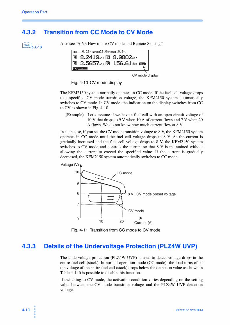
4-10 KFM2150 SYSTEM
Operation Part
4.3.2 Transition from CC Mode to CV Mode
p.A-18Also see “A.6.3 How to use CV mode and Remote Sensing.”
Fig. 4-10 CV mode display
The KFM2150 system normally operates in CC mode. If the fuel cell voltage dropsto a specified CV mode transition voltage, the KFM2150 system automaticallyswitches to CV mode. In CV mode, the indication on the display switches from CCto CV as shown in Fig. 4-10.
(Example) Let’s assume if we have a fuel cell with an open-circuit voltage of10 V that drops to 9 V when 10 A of current flows and 7 V when 20A flows. We do not know how much current flow at 8 V.
In such case, if you set the CV mode transition voltage to 8 V, the KFM2150 systemoperates in CC mode until the fuel cell voltage drops to 8 V. As the current isgradually increased and the fuel cell voltage drops to 8 V, the KFM2150 systemswitches to CV mode and controls the current so that 8 V is maintained withoutallowing the current to exceed the specified value. If the current is graduallydecreased, the KFM2150 system automatically switches to CC mode.
Fig. 4-11 Transition from CC mode to CV mode
4.3.3 Details of the Undervoltage Protection (PLZ4W UVP)
The undervoltage protection (PLZ4W UVP) is used to detect voltage drops in theentire fuel cell (stack). In normal operation mode (CC mode), the load turns off ifthe voltage of the entire fuel cell (stack) drops below the detection value as shown inTable 4-1. It is possible to disable this function.
If switching to CV mode, the activation condition varies depending on the settingvalue between the CV mode transition voltage and the PLZ4W UVP detectionvoltage.
See
CV mode display
0
10
Voltage (V)
Current (A)
CC mode
CV mode
: CV mode preset voltage
9
8
7
10 20
8 V

KFM2150 SYSTEM 4-11
Operation Part
Bas
ic O
per
atio
n
4
• (CV mode transition voltage) < (PLZ4W UVP detection voltage)
The undervoltage protection (PLZ4W UVP) is activated, and the load turns off(does not switch to CV mode) (Fig. 4-12-a).
• (CV mode transition voltage) > (PLZ4W UVP detection voltage)
The KFM2150 switches to CV mode (Fig. 4-12-b).
Fig. 4-12 PLZ4W UVP and CV mode transition voltage
4.3.4 Details of the Voltage Sensing Undervoltage Protection (SENSE UVP)
p.4-12The voltage sensing undervoltage protection (SENSE UVP) is used to detect theportion of the voltage drop where the impedance measurement is performed(detection section) such as in the unit of cell level of the fuel cell. In normaloperation mode (CC mode), the load turns off after UVP Mask Time elapses if thevoltage at the detection section drops below the detection value as shown in Table 4-1.
This function is independent feature from the function specified in the clause 4.3.3 of “undervoltage protection (PLZ4W UVP)”.
0
0
CV mode transition voltage
CV mode transition voltage
Voltage (V)
Current (A)
Voltage (V)
Current (A)
CC mode
Load offPLZ4W UVP detection voltage
PLZ4W UVP detection voltage
(a)
(b)
CC mode
CV mode
See

4-12 KFM2150 SYSTEM
Operation Part
4.3.5 Setting the Protection Function
This section describes the procedure to set the overpower protection (PLZ4W OPP),undervoltage protection (PLZ4W UVP), and voltage sensing undervoltageprotection (SENSE UVP).
1 Press the PROTECT key.
The PROTECT window appears.
Fig. 4-13 PROTECT window
2 Press the or key to select the protection item.
p.4-8Select overpower protection (PLZ4W OPP), undervoltage protection (PLZ4W UVP),or voltage sensing undervoltage protection (SENSE UVP).
3 Press the or key to select the digit you want to set.
4 Turn the rotary knob to set the value.
5 Press the ENTER key.
The PROTECT window closes.
Voltage Sensing UVP Mask Time
You can set a time (delay) until the voltage sensing undervoltage protection (SENSEUVP) is activated.
Select MENU key > Select Setup > Protection > UVP Mask Time to set.
The selectable range is 0 s to 10 s.
4.3.6 Alarm Occurrence and Release
When a protection function activates, an alarm is activated. If you cannot clear thealarm even when all of the causes of the alarm are eliminated, the KFM2150 systemmay have malfunctioned. If this happens, stop using the KFM2150 system andcontact your Kikusui agent or distributor.
Cause of alarms and remedies
Table 4-2 Cause of the alarm
PROTECT window
See
Activated protection function Cause of the alarm Remedy
Overpower protection (PLZ4W OPP) Overcurrent or increased fuel cell voltage
Review the operating or test condition of the fuel cell.
Undervoltage protection (PLZ4W UVP) Decreased voltage
Overvoltage protection (PLZ4W OVP) Increased voltage

KFM2150 SYSTEM 4-13
Operation Part
Bas
ic O
per
atio
n
4
When overpower protection (PLZ4W OPP) activates
When the overpower protection activates, “OPP” is shown at the bottom section ofthe display.
Fig. 4-14 OPP display
Review the operating or test condition of the fuel cell. When the alarm condition iscleared, the OPP indication clears, and the overpower protection is automaticallyreleased.
When other protection functions activates
When another protection function activates, an alarm message appears.
Fig. 4-15 Alarm message display example
1 Eliminate the cause of the alarm according to the alarm message.
The alarm will be activated again if you do not correct the cause of the alarm.
2 Press the ENTER key.
The alarm is cleared, and the alarm message display closes.
Reverse connection protection (PLZ4W REV) The connection to the fuel cell is incorrect.
Check the fuel cell wiring.
Overheat protection (PLZ4W OHP) Overheating of the PLZ-4W Series
Check that the vent holes of the PLZ-4W Series are not blocked and that the dust filter is not clogged.
Alarm input detection(USER)
Alarm signal input Clear the alarm of the device connected to the J1 connector of the KFM2150.
Voltage sensing undervoltage protection (SENSE UVP)
Decreased voltage in the voltage sensing input
Review the operating or test condition of the fuel cell.
PLZ-4W other(PLZ4W OTHER)
Causes other than those listed above
If the alarm occurs many times, contact your Kikusui agent or distributor
Activated protection function Cause of the alarm Remedy
OPP display

4-14 KFM2150 SYSTEM
Operation Part
4.4 Memory Function
The settings can be stored to the memories. There are three memories: A, B, and C.
For those memories, A, B, and C can be applied in each of current range (LOW,/MID/HIGH). In addition, the voltage range (15 V/150 V) can be also added to thesememories. By having those combinations of setting, there are up to 18 memories intotal.
p.4-26The KFM2150 uses the PLZ-4W Series by fixing the current range and voltagerange.
The current range is set using MENU key > Setup > DC Load > Range.
The voltage range is set using MENU key > Setup > DC Load > VRange
Saving to the memory
The settings that are saved are the items shown in Table 4-3 and menu items.
1 Press the STORE (SHIFT+RECALL) key.
The STORE window appears. The operation is not accepted if the connection to thePLZ-4W Series is incomplete and there is no response.
2 Turn the rotary knob to select the memory to save the settings.
The STORE window shows MEM-A, MEM-B, or MEM-C.
3 Press the ENTER key.
The STORE window closes. Saving of the settings is complete. The correspondingmemory icon is shown in the status display section.
Table 4-3 Settings stored to memory (other than menu items)
See
Stored setting Factory default settings
DC current 0 A
Protection function
Undervoltage protection (SENSE UVP)
-2 V
Overpower protection (PLZ4W OPP)
Maximum value of the PLZ-4W Series that are connected
Undervoltage protection (PLZ4W UVP)
OFF
Measurement method AC impedance method
AC impedance methodMeasuring frequency (FREQ) 20 kHz
Measuring AC current 10 %
Current interrupt
method
Pulse width (WIDTH) 10.0 ms
Pulse depth (DEPTH) 100 %
Pulse transition time (TRNSN) 0.01 ms
Average count (AVE) 1
Display (VIEW)
Upper left R
Lower left X
Upper right Z
Lower right θ

KFM2150 SYSTEM 4-15
Operation Part
Bas
ic O
per
atio
n
4
Recalling the memory
The memory corresponding to each range of the current and voltage can be recalledfrom A, B, or C.
1 Press the RECALL key.
A RECALL window appears. The operation is not accepted if the connection to thePLZ-4W Series is incomplete and there is no response.
2 Turn the rotary knob to select the memory to be recalled.
The RECALL window shows MEM-A, MEM-B, or MEM-C.
To cancel the recall operation, press the RECALL key again.
3 Press the ENTER key.
The RECALL window closes. The settings in the selected memory is recalled. Thecorresponding memory icon is shown in the status display section.
The memory is cleared if you change the settings, because the settings are no longerthe same as the contents of the recalled memory.

4-16 KFM2150 SYSTEM
Operation Part
4.5 Other Settings
Locking the panel operation
The KFM2150 has a lock function that prevents accidental operation. When locked,all keys other than the LOAD, RECALL, and LOCK (SHIFT+LOCAL) keys aredisabled.
Fig. 4-16 LOCK display
Setting the lock
Press the LOCAL (SHIFT+LOCAL) key. A beep is sounded, and the paneloperation is locked. “LOCK” is displayed in the bottom section of the display.
Releasing the lock
Press the LOCAL (SHIFT+LOCAL) key. Two beeps are sounded, and the lock isreleased. The LOCK indication clears.
Display contrast
You can adjust the display contrast by turning the rotary knob while holding downthe SHIFT key.
Turn the rotary knob clockwise increase or counterclockwise to decrease thecontrast.
Display color
You can select the display color.
1 Press the MENU key.
The MENU display appears.
2 Press the , , and arrow keys to move to Panel > LCD Color.
3 Turn the rotary knob to select the color (blue or white).
LOCK display

KFM2150 SYSTEM 4-17
Operation Part
Bas
ic O
per
atio
n
4
Switching from remote to local mode
Pressing the LOCAL key when the KFM2150 is being controlled remotely causesthe KFM2150 to switch to panel operation (local mode). The RMT LED illuminateswhen the KFM2150 is being controlled remotely.
Setting the alarm volume
You can adjust the alarm volume.
1 Press the MENU key.
The MENU display appears.
2 Press the , , and arrow keys to move to Panel > Beep Volume.
3 Turn the rotary knob to select the volume (0 to 255).
Factory default settings
p.A-6You can initialize the KFM2150 to factory default settings.
1 Press the INIT (SHIFT+MENU) key.
A confirmation window (INITIALIZE?) appears.
2 Press the ENTER key.
The confirmation window closes. The KFM2150 is initialized to factory defaultsettings.
See

4-18 KFM2150 SYSTEM
Operation Part
4.6 Setting the Remote Control
In addition to using the front panel, the KFM2150 can be controlled remotely usingthe following interfaces.
• RS232C interface
• GPIB interface
• USB interface
The factory default remote control interface setting is GPIB. The GPIB, RS232C,and USB interfaces cannot be used at the same time.
The remote interface complies with IEEE 488.2 std. 1992 and SCPI Specification1999.0. For details, see the Communication Interface Manual.
The KFM2150 conforms to the following standards.
• IEEE Std. 488.2-1992 IEEE Standard Codes, Formats, Protocols, and CommonCommands For Use With IEEE Std. 488-1987
• IEEE Std. 488.1-1987 IEEE Standard Digital Interface for ProgrammableInstrumentation
• Standard Commands for Programmable Instruments (SCPI) version 1999.0
• Universal Serial Bus Specification Rev 2.0
• Universal Serial Bus Test and Measurement Class Specification (USBTMC) Rev1.0
• Universal Serial Bus Test and Measurement Class, Subclass USB488Specification (USBTMC-USB488) Rev 1.0
4.6.1 GPIB Interface
Setting the GPIB address
Set the GPIB address between from1 to 30. As a factory default,it is set to 3.
1 Check that the load is turned off.
2 Press the MENU key.
The MENU display appears.
3 Press the , , and arrow keys to select Configuration >Interface > TYPE and turn the rotary knob to select GPIB.
4 Press the or arrow key to select Address, and turn the rotaryknob to set the address (1 to 30).
5 Press the MENU key.
The MENU display closes.

KFM2150 SYSTEM 4-19
Operation Part
Bas
ic O
per
atio
n
4
6 Turn the POWER switch off and then turn it back on.
The settings are fixed.
GPIB function
Table 4-4 GPIB functions
IEEE488.1 get, dcl, sdc, llo, and gtl commands
Service request
Service request and serial polling functions are implemented.
Function Subset Description
Source handshaking SH1 Full capability
Acceptor handshaking AH1 Full capability
Talker T6 Function available
Listener L4 Function available
Service request SR1 Full capability
Remote local RL1 Full capability
Parallel polling PP0 No capability
Device clear DC1 Full capability
Device trigger DT1 Function available
Controller C0 No capability
Electrical interface E1 Open collector driver
Command Description
get Group Execute TriggerFunctions as a software trigger for starting the measurement (equivalent to the *TRG command).
dcl/sdcDevice Clear/
Selected Device ClearAborts the measurement and clears the command buffer.
llo Local Lockout Locks out the local keys of the KFM2150.
gtl Go to Local Sets the KFM2150 front panel to local control.

4-20 KFM2150 SYSTEM
Operation Part
4.6.2 RS232C Interface
RS232C configuration
1 Check that the load is turned off.
2 Press the MENU key.
The MENU display appears.
3 Press the , , and arrow keys to select Configuration >Interface > TYPE and turn the rotary knob to select RS232C.
4 Press the or arrow key to select Baudrate, and turn the rotaryknob to set the baud rate.
5 Likewise, set Data, Stop, Parity, and Ack.
6 Press the MENU key.
The MENU display closes.
7 Turn the POWER switch off and then turn it back on.
The settings are fixed.
Protocol
Table 4-5 shows the RS232C protocol.
Underline indicates factory default setting.
Table 4-5 RS232C protocol
Break signal
The break signal functions as a substitute for the IEEE488.1 dcl/sdc (Device Clear,Selected Device Clear) message.
RS232C communication
Use X-Flow control or acknowledge function for RS232C communication.
Transmission/reception may not work correctly through unilateral transmission.
Item Setting
Connector 9-pin D-sub terminal on the rear panel
Baudrate 2400 bps, 4800 bps, 9600 bps, or 19200 bps
Data (data length) 7 bits or 8 bits
Stop (stop bit) 1 bit or 2 bits
Parity Fixed to none
Ack (acknowledge) ON or OFF

KFM2150 SYSTEM 4-21
Operation Part
Bas
ic O
per
atio
n
4
X-Flow control
The transmission/reception on the KFM2150 can be controlled using Xon/Xoff.
DC (device control) codes are used as control codes.
Table 4-6 DC codes
Fig. 4-17 RS232C terminal and transmission control of the KFM2150
Acknowledge message
An acknowledge message is information sent from the KFM2150 to the controller.It notifies that the processing of the program message has been completed.
The acknowledge message is an ASCII code string consisting of only the header.The following two types are available.
• OK: Normal completion
• ERROR: Error such as a syntax error or query error
p.4-20To use acknowledge messages, set Ack to On in the CONFIG settings.
On the controller, the RS232C configuration must be set to full-duplex operation.
Code Function ASCII code
DC1Transmission
request11H
DC3Transmission stop request
13H
DC3RXD DC1
TXD
After receiving DC3, the KFM2150 pauses transmission within 3 characters.
Within 3 characters
Pause Resume transmission
Resume transmission
Transmission control from the RS232C terminal to the KFM2150
DC3TXD
RXD
The RS232C terminal must pause transmission within 10 characters after receiving DC3.
Within 10 characters
Transmission control from the KFM2150 to the RS232C terminal
DC1Pause
See

4-22 KFM2150 SYSTEM
Operation Part
4.6.3 USB Interface
A device driver supporting USB T&M Class (USBTMC) is required to control theKFM2150 through the USB interface. The USBTMC driver is automaticallyinstalled by one of the VISA libraries below.
KI-VISA 2.2.x or later
(downloadable from KIKUSUI Website:http://www.kikusui.co.jp/en/download/)
• NI-VISA 3.0 or later (downloadable from National Instruments Website)
• Agilent VISA (Agilent I/O Libraries) M01.00 or later (downloadable from Agilent Technologies Website)
USB configuration
1 Check that the load is turned off.
2 Press the MENU key.
The MENU display appears.
3 Press the , , and arrow keys to select Configuration >Interface > TYPE and turn the rotary knob to select USB.
4 Press the MENU key.
The MENU display closes.
5 Turn the POWER switch off and then turn it back on.
The settings are fixed.
Service request
Service request and serial polling functions are implemented.
USB function
Complies with USB Specification 2.0.
Complies with USBTMC Specification 1.0 and USBTMC-USB488 Specification1.0.
Data rate: 12 Mbps maximum (full speed).
VID (vendor ID): 0x0B3E.
PID (product ID): 0x1008.

KFM2150 SYSTEM 4-23
Operation Part
Bas
ic O
per
atio
n
4
4.6.4 Command Details
For command details, see the Communication Interface Manual on theaccompanying CD-ROM.
The communication interface manual is provided in HTML format. You can view itusing the following browser.
Operating environment: Windows 98 or later
Browser: Microsoft Internet Explorer 5.5 or later
The list of messages in the communication interface manual is provided in PDFformat. Adobe Reader 6.0 or later is required to view the list.

4-24 KFM2150 SYSTEM
Operation Part
4.7 Installing the Application Software (FCTester)
PC system requirements
CPU Pentium III 600 MHz or faster
OS Microsoft Windows 2000 or XP
Memory 256 MB or more (512 MB or more recommended) or 512MB or more (1 GB or more recommended) when using thescanner.
Display resolution SVGA resolution or higher (800 × 600 dots or higher)
Hard disk 20 MB of free space is needed to save files
CD-ROM drive
Mouse or pointing device
Data analysis Microsoft Excel
I/O interface One of the following is required.• USB• RS232C• GPIB(National Instruments, Agilent Technologies, Contec Co., LTD. or Interface Co., Ltd.)
VISA library NI-VISA3.0 or later, Agilent I/O Library M01.00 or later,or KI-VISA 2.5 or later
• Turn off the power-saving mode on the OS, screen savers, and memory-residentprograms.
• Avoid using the software with other applications.
Contents of the accompanying CD-ROM
• Application software
FCTester and PLZ Detach
• Instrument driver
KI-VISA 3.x.xThe value for x varies depending on the revision of the VISA library stored on the CD-ROM.
• Document
Communication Interface Manual (English and Japanese)

KFM2150 SYSTEM 4-25
Operation Part
Bas
ic O
per
atio
n
4
Installation
1 Load the accompanying CD-ROM into the CD-ROM drive.
2 Install the applications according to the instructions on the screen.
The operation manuals of the application softwares are stored on the CD-ROM.
Environmental settings
KFM2150 settings
p.4-18Set the interface that is to be used.
FCTester settings
Use the FCTester Configuration Tool to set the VISA resource to match theKFM2150 interface. For details, see chapter 3, “System Configuration” in theoperation manual of the application software.
See

4-26 KFM2150 SYSTEM
Operation Part
4.8 Details on Menu Setup
Menu Operation Basics
1 Check that the load is turned off.
2 Press the MENU key.
The MENU display appears.
3 Press the arrow keys ( , , , and ) to move to the conditionyou want to set.
4 Turn the rotary knob to set the condition.
To set other conditions, repeat steps 3 and 4.
5 Press the MENU key.
The MENU display closes.
Menu items
Underlined values or status are factory default values.
Table 4-7 Menu items
Item 1 Item 2 Item 3 Conditions Description Page
Setup
Soft Start Time
Rise0:00 to 2:00
(Hour: minute)Soft start rise time.
p.5-7
Fall0:00 to 2:00
(Hour: minute)Soft start fall time.
Input SelectVoltage Sensing 1/2
Select channel 1 or 2 according to the terminal you are using.
p.2-12p.3-10
Current Sensing 1/2 Normally, select channel 1. p.A-4*1
DC Load
Range*2 LOW/MID/HIGHLoad current range of the PLZ-4W Series.
p.5-4
VRange*2 15 V/150 VVoltage range of the PLZ-4W Series.
p.5-5Voltage 0 V to 157.5 V
Sets the CV mode transition voltage of the PLZ-4W Series.
Aux DC Load
Output 0 A to 3500 A*3 Sets the load current of the external electronic load unit.
p.A-2
iR Sampling
Position0.00 ms to 9.99 ms
(0.06 ms)Sampling start position of the current interrupt method
p.5-16
Region0.002, 0.006, 0.014,0.030, 0.062, 0.126,0.254, or 0.510 ms
Sampling region of the current interrupt method.
Protection UVP Mask Time0 s to 10 s
(4 s)
Sets the time for starting the activation after SENSE UVP is detected.
p.4-12
CorrectionShort
CorrectNone Disable or Enable Short-circuit correction function. p.5-21

KFM2150 SYSTEM 4-27
Operation Part
Bas
ic O
per
atio
n
4
Judge
GO or NOGO Judge
Condition
None Disable or Enable Judgement function. p.5-24
Configurati
on*4
Interface
Interface TypeGPIB, RS232C, or
USBInterface.
p.4-18
GPIB Address 1 to 30 (3) GPIB address.
RS232C
Baudrate2400, 4800, 9600, or
19200 bpsBaud rate.
Data 8 bits or 7 bits Data length.
Stop 1 bit/2 bits Stop bit.
Parity NONE Parity.
Ack OFF/ON Acknowledge message.
USB
VID0x0B3E (display
only)Vendor ID.
PID 0x1008 (display only) Product ID.
S/N xxxx (display only) Serial number.
Alarm Alarm Status Lo/HiAlarm status output(J1 connector #16 terminal)
p.A-5
DC Load
Load On Output Lo/HiLoad on/off control signal output.(CONTROL TERMINAL #3 terminal)
p.A-3
Load On Status Lo/HiLoad on status output.(J1 connector #13 terminal)
p.A-5
Aux DC Load
Control0.00 V to 10.50 V
(10.00 V)
Control voltage used to supply the maximum load current of the external electronic load unit. p.A-2
Full Scale0 A to 3500 A
(200 A)Maximum load current of the external electronic load unit.
Option Scanner Disable/Enable Scanner (KFM2151) function. p.A-34
PanelBeep Volume 0 to 255 (64) Alarm volume. p.4-17
LCD Color Blue/White LCD color. p.4-16
model
Info*5
Model KFM2150 KFM2150 model.
-
Version 1.1X KFM2150 firmware version.
Serial No. AB123456 (example) KFM2150 serial number.
PLZ-4W
PLZ1004W (example)
Model of the master unit.
AB123456 (example) Serial number of the master unit.
VerX.XX (example)Firmware version of the master unit.
P:2 (example: parallel operation) B:3(example: booster)
Number of parallel units or boosters.
*1. Channel 2 is used when connecting an external current detector.*2. You cannot switch the range while the load is turned on.*3. The selectable maximum value is the value specified by Configuration > Aux DC Load > Full Scale.*4. Configuration conditions are fixed when you turn the POWER switch off and then turn it back on.*5. Information about the KFM2150 and the PLZ-4W Series. These items cannot be changed.
Item 1 Item 2 Item 3 Conditions Description Page

4-28 KFM2150 SYSTEM
Operation Part

Impedance MeasurementThis chapter describes the impedance measurement and loadcurrent settings.

5-2 KFM2150 SYSTEM
Operation Part
5.1 Impedance Measurement Basics
5.1.1 Running the Load CurrentA load is connected to the fuel cell, and the load current is supplied. By changingthe load current and measuring the cell voltage, you can determine the current andvoltage characteristics as shown in Fig. 5-1. The KFM2150 system uses the PLZ-4W Series Electronic Load Unit to run the load current.
Fig. 5-1 Current and voltage characteristics
5.1.2 Operating Status of the Fuel Cell and Impedance Measurement
Measurement basics
The impedance characteristics are measured by supplying the load current tooperate the fuel cell. There are two measurement methods: AC impedance methodand current interrupt method.
The measurement is carried out in the load-on period of Fig. 5-2.
Fig. 5-2 Measurement and the operating status of the fuel cell
Synchronizing to the start and end times of the fuel cell (soft start)
The load current can be gradually increased or decreased to match the start and endtimes of the fuel cell.
The measuring AC current used to measure the impedance is set as a percentage ofthe load current. The measuring AC current can also be set as a current value in theAC impedance method.
0
Fuel cell Electronic Load Unit
V I
Cell voltage
Current density
Load current
Soft startrise time
Soft startfall time
Impedance measurement
Load on
Start End

KFM2150 SYSTEM 5-3
Operation Part
Imp
edan
ce M
easu
rem
ent
5
5.1.3 Impedance Measurement System
System component instruments fixed at the factory
The KFM2150 is shipped with the serial number of the PLZ-4W Series ElectronicLoad Units registered as system component instruments. The PLZ-4Ws cannot besubstitute as a replacement even if they are of the same model.
The combination of the KFM2150 and the PLZ-4W Series is checked at power-on.If it is different from the combination registered at the factory, an error occurs.
Functional assignments of the KFM2150 and PLZ-4W Series
The KFM2150 controls the system. The load current of the fuel cell and impedancemeasuring AC current flow through the PLZ-4W Series. The current signal ispassed from the PLZ-4W Series to the KFM2150. The voltage signal for theimpedance measurement enters the KFM2150 directly from the fuel cell.
Fig. 5-3 Overview of the functional assignments
Fuel cell PLZ-4W Series
KFM2150
Load current+
Measuring AC current
Current signalVoltage signal
Impedance Measurement

5-4 KFM2150 SYSTEM
Operation Part
5.2 Setting the Load Current
This system operates in CC+CV mode, in which the system automatically switchesbetween CC mode and CV mode. During normal operation, the system operates inCC mode, in which constant current runs independent of the voltage. If constantcurrent can no longer run in CC mode, the system switches to CV mode andprevents overcurrent from flowing by maintaining the preset voltage.
CC (constant current) mode
CC mode allows a constant current to be run regardless of the voltage. Thecurrent value can be set in detail.
CV (constant voltage) mode
CV mode allows current to be run so that the voltage is kept constant. Thevoltage value can be set in detail.
5.2.1 Setting the Current Range
The selectable range of the load current is determined by the model configuration of thePLZ-4W Series and the current range of the PLZ-4W Series.
Select MENU key > Select Setup > DC Load > Range to select the PLZ-4W range(LOW, MID, or HIGH).
p.7-2• Select the range of the PLZ-4W Series for the load current you want to set. The
load current that you can set varies depending on the system type. For details,see selectable range (range L, M, and H) in 7.1, “ Basic Performance.”
• LOW, MID, and HIGH in the menu correspond to L, M, and H in 7.1, “ BasicPerformance.”
• You cannot switch the range while the load is turned on.
See

KFM2150 SYSTEM 5-5
Operation Part
Imp
edan
ce M
easu
rem
ent
5
5.2.2 Setting the Current of CC Mode
The fuel cell is run at a given load (CC mode) such as in the I-V characteristics test.Set the measuring AC current used in the AC impedance method to zero.
Fig. 5-4 Setting the load current
1 Press the DC key.
The cursor moves to DC on the display.
2 Turn the rotary knob to set the load current.
Use the or key to specify the digit.
3 Press the AC key.
The cursor moves to AC on the display.
The unit switches between % and A each time you press the key.
4 Turn the rotary knob to set the measuring AC current to 0 A or 0.0 %.
5.2.3 Setting the CV mode transition voltage
The CV mode transition voltage is set from the menu.
1 Press the MENU key.
The MENU display appears.
2 Press the , , and arrow keys to move to Setup > DC Load >VRange.
3 Turn the rotary knob to select the voltage range (15 V or 150 V).
4 Press the , , and arrow keys to move to Setup > DC Load >Voltage.
5 Turn the rotary knob to set the voltage.
The PLZ-4W series setting range is set depending on the VRange setting as follows:
VRange setting PLZ-4W series setting range
150 V 0 V to 157.5 V
15 V 0 V to 15.75 V

5-6 KFM2150 SYSTEM
Operation Part
5.3 Turning the Load On/Off (Turning the Load Current On/Off)
The phrase “turn the load on” is to define the supplying load current to the load. Thephrase “turn the load off” is to define the shutting off the load current. The soft startfunction allows the load current to gradually increase when the load is turned on(soft start rising edge) or gradually decrease when the load is turned off (soft startfalling edge).
You can turn the load on and off using keys. If a protection function is activated, theload is automatically turned off.
When the load is turned on, impedance measurement is executed. The measurementterminates when the load is turned off.
Four status of the load current
• Load on: The load current is at the preset constant current.
• Load off: No load current flows.
• Soft start rising edge: The load current gradually increases.
• Soft start falling edge: The load current gradually decreases.
Fig. 5-5 Load current state
Load current
Soft startrising edge
Soft startfalling edge
Impedance measurement
Load current
Load on
Load on
Start End
Load off
Load off
Load off
Load off
Setting
Setting

KFM2150 SYSTEM 5-7
Operation Part
Imp
edan
ce M
easu
rem
ent
5
Details of soft start
The load current is changed step-wise at 1-s interval (Fig. 5-6). The step current isequal to the load current divided by the soft start time (in unit of seconds).
(Example) When the load current is 60 A and the soft start time is 10 minutes,the step current is 0.1 A.
Fig. 5-6 Soft start
Setting the soft start time
The soft start rise time and soft start fall time are set according to the operatingcharacteristics of the fuel cell in advance.
1 Select MENU key > Setup > Soft Start Time > Rise to set the soft startrise time.The selectable range is 0 hour 00 minute to 2 hour 00 minute.
2 Select MENU key > Setup > Soft Start Time > Fall to set the soft startfall time.The selectable range is 0 hour 00 minute to 2 hour 00 minute.
Impedance measurement
When the load current reaches the preset constant current, the impedancemeasurement is started. In other words, the measurement is executed when the loadis on and terminated when the load is off. The measurement is not executed duringthe period between the soft start rise time and soft start fall time.
60 [minutes] = 0.1 [A]
10 [minutes] 60×
Load current
Soft startrise time
Load on
Soft startfall time
Trs Tfs Trs:
Tfs:
Time
Load current
Trs [minutes] × 60
Step current
Step current =
1 s
Rising edge:
Load current
Tfs [minutes] × 60Step current =
Falling edge:
Setting

5-8 KFM2150 SYSTEM
Operation Part
5.3.1 Load On and Soft Start Rising Edge
Table 5-1 indicates the operation and behavior of load on and soft start rising edge.
• To turn the load on, be sure that the load current settings, connection tothe fuel cell, polarity, wire selection, and the other settings are correct.
Table 5-1 Load on and soft start rising edge operation
CAUTION
Load on Soft start rising edge
Condition immediately before the operation
Load current Zero
LOAD LED Off
Operation Press the LOAD key.Press the SOFT START (SHIFT+LOAD) key.
Behavior or condition immediately after the operation
Load current The load turns on immediately. Gradually increases from zero.
LOAD LED On Blinking
Time display NoneShows on the display the remaining time until the preset load current is reached.
Load on period
LOAD LED On
Time display None
Load current
Time
Operation timing

KFM2150 SYSTEM 5-9
Operation Part
Imp
edan
ce M
easu
rem
ent
5
5.3.2 Load Off and Soft Start Falling Edge
Table 5-2 indicates the operation and behavior of load off and soft start falling edge.
Table 5-2 Load off and soft start falling edge operation
5.3.3 Protection Function and Load Off
When the following protection functions are activated, the KFM2150 turns the loadoff.
p.4-8• Overvoltage protection (PLZ4W OVP)
• Undervoltage protection (PLZ4W UVP)
• Reverse connection protection (PLZ4W REV)
• Overheat protection (PLZ4W OHP)
• Alarm input detection (USER)
• Voltage sensing undervoltage protection (SENSE UVP)
Load off during soft start falling edge
Soft start falling edge during soft start rising edge
Load off Soft start falling edge
Load off during soft start rising edge
Condition immediately before the operation
Load current
Gradually increases from zero. Operating at the specified load current. Gradually decrease.
LOAD LED
Blinking On Blinking
Time display
Shows on the display the remaining time until the preset load current is reached.
None
Shows on the display the remaining time until the load current falls to zero.
Operation
Press the LOAD key.
Press the SOFT START (SHIFT+LOAD) key.
Press the LOAD key.
Press the SOFT START (SHIFT+LOAD) key.
Press the LOAD key.
Behavior or condition immediately after the operation
Load current
The load turns off immediately.
Gradually decrease.
The load turns off immediately.
Gradually decrease.
The load turns off immediately.
LOAD LED
Off Blinking Off Blinking Off
Time display
None
Shows on the display the remaining time until the load current falls to zero.
None
Shows on the display the remaining time until the load current falls to zero.
None
Loadoff period
LOAD LED
Off
Time display
None
Load current
Time
Operation timing
See

5-10 KFM2150 SYSTEM
Operation Part
5.4 AC Impedance MethodSelect the AC impedance method from the two available impedance measurementmethods (AC impedance and current interrupt methods). The measurement methodcan be switched regardless of whether the load is turned on/off.
The settings required for the measurement are the frequency and value of themeasuring AC current.
You can set the measurement conditions of the AC impedance method and switch tothe AC impedance method while measurement is in progress using the currentinterrupt method. The new measurement conditions are activated when themeasurement method is switched.
The load current maintains the previous setting even if the measurement method isswitched.
Measurement items
Fig. 5-7 Setup display of the AC impedance method
Frequency and value of the measuring AC currentFig. 5-8 shows a conceptual diagram of the frequency (FREQ) and value (AC) of themeasuring AC current. Because the percentage with respect to the load current takesprecedence for the measuring AC current, changing the load current also changesthe measuring AC current. Even when an absolute value is used to set the measuringAC current, it is stored as a percentage in the KFM2150.
Fig. 5-8 Measuring AC current
R Resistance
X Reactance
Z Absolute value of the impedance
θ Phase angle
VcycleMeasured voltage (voltage synchronized to the impedance measurement)
Icycle Load current (current synchronized to the impedance measurement)
V Measured voltage (voltage measured at a fixed cycle of the voltmeter)
I Load current (current measured at a fixed cycle of the ammeter)
Time
Load current+
AC current
AC
Load current1
FREQ

KFM2150 SYSTEM 5-11
Operation Part
Imp
edan
ce M
easu
rem
ent
5
5.4.1 Selecting the measurement method
When the load is turned off
Press the METHOD key to select .It is selected for the AC impedance method. By pressing the METHOD key, it
switches between AC impedance method ( ) and current interrupt method ( ).
The LED of the selected method is illuminated.
When the load is turned on
1 Press the METHOD key.
A confirmation of (METHOD CHANGE?) is appeared on the display. Check that it isokay to change the measurement method.
2 Press the ENTER key.
It is selected the measurement method.
• The confirmation display (METHOD CHANGE?) appears even during the softstart rise time or soft start fall time.
5.4.2 Setting the measuring frequency
1 Press the FREQ key.
The cursor moves to FREQ on the display.
The cursor moves to FREQ also when using the current interrupt method.
2 Turn the rotary knob to set the measuring frequency.
You can select from the frequencies that result by multiplying the values in column Aby the values in column B.
The lower and upper limits are 10 mHz and 20 kHz, respectively.
Turn the rotary clockwise to increase the value and counterclockwise to decrease thevalue.
• When the measuring frequency is low (less than or equal to 1 Hz), the intervalfor updating the display is longer. The measured result of impedance variesdepending on the measuring frequency. The display update interval isapproximately equal to the interval of the measuring frequency.
A B
1.00, 1.26, 1.58, 2.00, 2.51, 3.00, 3.16, 4.00, 5.00, 6.00, 6.30, 7.00, 8.00, 9.00
×10 mHz, ×100 m Hz, ×1 Hz, ×10 Hz, ×100 Hz, ×1 kHz, ×10 kHz
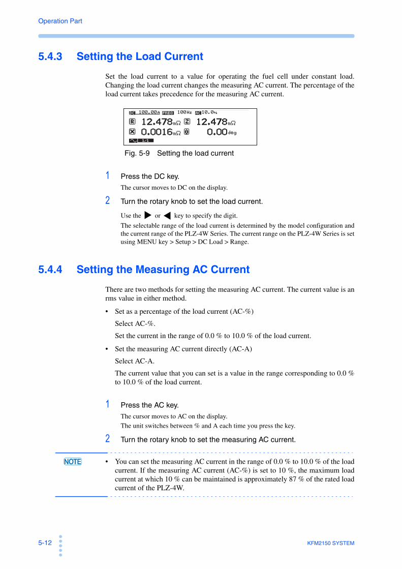
5-12 KFM2150 SYSTEM
Operation Part
5.4.3 Setting the Load Current
Set the load current to a value for operating the fuel cell under constant load.Changing the load current changes the measuring AC current. The percentage of theload current takes precedence for the measuring AC current.
Fig. 5-9 Setting the load current
1 Press the DC key.
The cursor moves to DC on the display.
2 Turn the rotary knob to set the load current.
Use the or key to specify the digit.
The selectable range of the load current is determined by the model configuration andthe current range of the PLZ-4W Series. The current range on the PLZ-4W Series is setusing MENU key > Setup > DC Load > Range.
5.4.4 Setting the Measuring AC Current
There are two methods for setting the measuring AC current. The current value is anrms value in either method.
• Set as a percentage of the load current (AC-%)
Select AC-%.
Set the current in the range of 0.0 % to 10.0 % of the load current.
• Set the measuring AC current directly (AC-A)
Select AC-A.
The current value that you can set is a value in the range corresponding to 0.0 %to 10.0 % of the load current.
1 Press the AC key.
The cursor moves to AC on the display.
The unit switches between % and A each time you press the key.
2 Turn the rotary knob to set the measuring AC current.
• You can set the measuring AC current in the range of 0.0 % to 10.0 % of the loadcurrent. If the measuring AC current (AC-%) is set to 10 %, the maximum loadcurrent at which 10 % can be maintained is approximately 87 % of the rated loadcurrent of the PLZ-4W.

KFM2150 SYSTEM 5-13
Operation Part
Imp
edan
ce M
easu
rem
ent
5
Measuring AC current as a percentage of the load current
Set the measuring AC current as a percentage of the load current. The percentage isheld constant. However, the ratio changes in the following condition.
• When the sum of the load current and the measuring AC current exceeds therated load current of the PLZ-4W Series (Fig. 5-10 (c)).
The load current setting takes precedence in the above condition. When the loadcurrent is increased, the measuring AC current is decreased so that the sum of theload current and the peak value of the measuring AC current is equal to the ratedload current of the PLZ-4W Series. Therefore, the measuring AC current that youspecified as a percentage of the load current decreases (Fig. 5-10 (c).
If you decrease the load current in this condition, the decreased percentage does notreturn to the original value (Fig. 5-10 (d)).
You can reset the decreased percentage back to the original value.
Fig. 5-10 Relationship between the measuring AC current and load current
Table 5-3 Relationship between the measuring AC current and load current (example when PLZrate = 200 A)
(a) (b) (c) (d)
DC
DC: Load currentAC-Apeak: Peak value of AC-APLZrate: Rated load current of the PLZ-4W Series
ACpeak
DC
ACpeak
DC
ACpeak
DC
ACpeak
DC+AC
PLZrate
Fig. 5-10 (a)
(b)
(c)
(d)Load current and
measuring AC current
(DC+AC-Apeak)
< PLZrate
(DC+AC-Apeak)= PLZrate
(DC+AC-Apeak)
> PLZrate
(DC+AC-Apeak)
< PLZrate
DC 100 A Increase 175.4 A Increase 190 A Decrease 100 A
AC-%*1 10 % Fixed 9.9 %Change, limit, and
store the limit*23.7 %*3 Limit*4 3.7 %*5
AC-A*6 10 Arms Change 17.36 Arms Change 7.03 Arms Change 3.7 A
*1. AC-%: Rms measuring AC current as a percentage of the load current*2. When the sum of the load current and the measuring AC current exceeds the rated load current of the PLZ-
4W Series, the sum of the load current and the peak value of the measuring AC current is limited to therated load current of the PLZ-4W Series. In this condition, the load current setting takes precedence, andthe measuring AC current decreases. The percentage with respect to the load current changes.
*3. The percentage with respect to the load current changes from the specified 10 % to 3.7 %.*4. If you decrease the load current, the decreased percentage does not return to the original value.*5. The value 3.7 % maintained.*6. AC-A: Measuring AC current as an rms current value.

5-14 KFM2150 SYSTEM
Operation Part
5.5 Current Interrupt Method
Select the “current interrupt method” from the two available impedancemeasurement methods (AC impedance and current interrupt methods). Themeasurement method can be switched regardless of whether the load is turned on/off.
The settings required for the measurement are the pulse width, depth, and transitiontime (rise and fall time) of the interrupt current.
You can set the measurement conditions of the current interrupt method and switchto the current interrupt method while measurement is in progress using the ACimpedance method. The new measurement conditions are activated when themeasurement method is switched.
The load current maintains the previous setting even if the measurement method isswitched.
Measurement items
Fig. 5-11 Setup display of the current interrupt method
Pulse width, depth, and transition time of the interrupt current
Fig. 5-12 shows a conceptual diagram of the pulse width (PW), depth (PD), andtransition time (PT) of the interrupt current that changes as a pulse. The repetitionperiod of the pulse (T) is fixed to 100 ms.
Because the percentage with respect to the load current takes precedence for thepulse width, changing the load current also changes the pulse depth.
Fig. 5-12 Interrupt current pulse
IR Internal resistance
VcycleMeasured voltage (voltage synchronized to the impedance measurement)
Icycle Load current (current synchronized to the impedance measurement)
V Measured voltage (voltage measured at a fixed cycle of the voltmeter)
I Load current (current measured at a fixed cycle of the ammeter)
PW
PT1
PT1 = PT2
PT2
PD
T = 100 ms (fixed)Load current
Time
Load current+
Interrupt current

KFM2150 SYSTEM 5-15
Operation Part
Imp
edan
ce M
easu
rem
ent
5
Sampling (current interrupt method)
To obtain stable measurement results, set the sampling start position (Position: timefrom interrupt start) and the sampling region (Region).
5.5.1 Selecting the Measurement Method
When the load is turned off
Press the METHOD key to select .
It is selected for the current interrupt method. By pressing the METHOD key, it
switches between AC impedance method ( ) and current interrupt method( ). The LED of the selected method is illuminated.
When the load is turned on
1 Press the METHOD key.
A confirmation of (METHOD CHANGE?) is appeared on the display. Check that it isokay to change the measurement method.
2 Press the ENTER key.
It is selected the measurement method.
• The confirmation display (METHOD CHANGE?) appears even during the softstart rise time or soft start fall time.
5.5.2 Setting the Pulse Width
1 Press the WIDTH key.
The cursor moves to PW on the display.
2 Turn the rotary knob to set the pulse width (0.1 ms to 10.0 ms).
5.5.3 Setting the Pulse Depth
There are two methods for setting the pulse depth.
• Set as a percentage of the load current (PD-%)
Select PD-% to set the current value of the pulse depth in the range of 0 % to 100% of the load current.
• Set the current value of the pulse depth directly (PD-A)
Select PD-A to set the current value of the pulse depth directly.

5-16 KFM2150 SYSTEM
Operation Part
1 Press the DEPTH key.
The cursor moves to PD on the display.
The unit switches between % and A each time you press the key.
2 Turn the rotary knob to set the pulse width.
5.5.4 Setting the Pulse Transition Time
1 Press the TRNSN key.
The cursor moves to PT on the display.
2 Turn the rotary knob to set the pulse transition time (0.01 ms to 10.00ms).
• The lower limit of the selectable range may be limited to a value greater than0.01 ms. If the pulse transition time exceeds 0.01 ms depending on therelationship between the specified pulse depth, load current, and the slew rate ofthe PLZ-4W Series, the lower limit of the selectable range is set to a valuegreater than 0.01 ms.
5.5.5 Setting the Sampling
Internal resistance IR is determined by computation using the values measuredaccording to the specified sampling start position (Position) and sampling region(Region).
Set the sampling start position and sampling region from the menu.
Fig. 5-13 Sampling start position and region
PWPT1 PT2
PD
Load current
Time
Load current+
Interrupt current
Ringing section
Position
Sensing voltage
Position
Region
Region
Position: Sampling start positionRegion: Sampling regionPT: Transition timePW: Pulse widthPD: Depth

KFM2150 SYSTEM 5-17
Operation Part
Imp
edan
ce M
easu
rem
ent
5
Sampling start position
Select MENU key > Setup > iR Sampling > Position to set the sampling startposition.
Position specifies the time from when the pulse transition time has elapsed since theinterrupt start till when sampling is started. As shown in Fig. 5-13, set the positionso that the ringing section after the pulse transition time is avoided.
The selectable range is 0.00 ms to 9.99 ms. It is the time from the start point ofthe pulse change.
Sampling region
Select MENU key > Setup > iR Sampling > Region to set the sampling region.
Region specifies the time from the sampling start point till when sampling isfinished. Set the region according to the time constant of the fuel cell. The selectablerange is the following eight points (ms unit).
0.002, 0.006, 0.014, 0.030, 0.062, 0.126, 0.254, or 0.510
Detailed explanation of sampling
p.A-30An example regarding the pulse transition time (PT), sampling start position, andsampling region is given in the appendix.
5.5.6 Setting the Load Current
Set the load current to a value for operating the fuel cell under constant load.Changing the load current changes the pulse depth of the interrupt current. Thepercentage with respect to the load current takes precedence for the pulse width ofthe interrupt current.
The selectable range of the pulse transition time may be limited depending on therelationship between the response speed of the PLZ-4W Series and the load current.
Fig. 5-14 Setting the load current
1 Press the DC key.
The cursor moves to DC on the display.
2 Turn the rotary knob to set the load current.
Use the or key to specify the digit.
The selectable range of the load current is determined by the model configuration andthe current range of the PLZ-4W Series. The current range on the PLZ-4W Series is setusing Menu key > Setup > DC Load > Range.
See

5-18 KFM2150 SYSTEM
Operation Part
5.6 Setting the Average Count
The measured value of the KFM2150 is averaged by the specified count (movingaverage).
Measurement items that can be averaged
AC impedance method: Resistance, reactance, magnitude of the impedance,phase angle, voltage (impedance measurementcycle), and load current (impedance measurementcycle).
Current interrupt method: Internal resistance, voltage (impedance measurementcycle), and load current (impedance measurementcycle).
1 Press the AVE key.
A setup window appears.
2 Turn the rotary knob to set the average count.
The selectable average counts are 1, 2, 4, 8, 16, 32, 64, 128, or 256.
3 Press the AVE key.
The setup window closes.
Fig. 5-15 When the average count is set to 4
n -3 n -2 n -1 n n +1 n +2 n +3
n to n +3
n-1 to n +2
n-2 to n+1
n-3 to n
n-4 to n-1
n-5 to n-2
n-6 to n-3
n: Arbitrary impedance measurement period
Measured values
: Averaging period
: Time when averaging is performed

KFM2150 SYSTEM 5-19
Operation Part
Imp
edan
ce M
easu
rem
ent
5
5.7 Displaying the Measured Results
You can select the items to be shown on the display and their positions.
Fig. 5-16 Display setup window
Selecting the items to be displayed and their positions
1 Press the VIEW key.
The display setup window (Fig. 5-16) appears according to the current measurementmethod.
2 Select the display position using the cursor keys.
3 Turn the rotary knob to select the displayed item.
Table 5-4 shows the displayed items.
4 Press the VIEW key.
The display setup window closes.
Table 5-4 Displayed items
Displayed item Description
OFF No display.
AC impedance method R Resistance.
X Reactance.
Z Absolute value of the impedance.
θ Phase angle.
Current interrupt method
IR Internal resistance.
Vcy (Vcycle) Measured voltage (voltage synchronized to the impedance measurement).
Icy (Icycle) Load current (current synchronized to the impedance measurement).
V Measured voltage (voltage measured at a fixed cycle of the voltmeter).
I Load current (current measured at a fixed cycle of the ammeter).
AC impedance method
Current interrupt method

5-20 KFM2150 SYSTEM
Operation Part
Difference between Vcycle/ Icycle and V/ I
Fig. 5-17 Measurement cycle
Measured results of the scanner system
For a scanner system that incorporates the KFM2151 FC Scanner, a scanner display( ) is shown as in Fig. 5-18. The voltage signal that the KFM2150 receives fromthe KFM2151 is processed internally and used in the impedance and voltagemeasurements.
As a result, the measurement accuracy of the displayed items of Table 5-4, is thesum of the basic measurement accuracy of the KFM2150 and the value specified inthe KFM2151 specifications.
However, the value specified in the KFM2151 specifications is not added for Icycleand I, because they are not received from the KFM2151.
Fig. 5-18 Scanner display
Impedance measurement cycleVcycle and Icycle
Voltmeter and ammeter cycleV and I
m m+1m-1m-2m-3m-4m-5m-6 m+2 m+3 m+4 m+5 m+6
m: Arbitrary voltmeter and ammeter measurement period
n-3 n-2 n-1 n n+1 n+2 n+3
n to n+3
n-1 to n+2
n-2 to n+1
n-3 to n
n-4 to n-1
n-5 to n-2
n-6 to n-3
n: Arbitrary impedance measurement period
Measured values
: Averaging period
: Time when averaging is performed
Scanner display

KFM2150 SYSTEM 5-21
Operation Part
Imp
edan
ce M
easu
rem
ent
5
5.8 Short-Circuit Correction Function
The short-circuit correction is a function used in the AC impedance method.
The KFM2150 can measure minute impedance. The measured result is affected bythe wiring impedance in the connection of the PLZ-4W Series and the fuel cell. Theshort-circuit correction function is available to minimize this effect.
The short-circuit correction function is set on the menu display.
Fig. 5-19 Shorting the voltage sensing wires
• The short-circuit correction function is carried out during measurement.When turning the load on, be sure that the load current settings,connection to the fuel cell, polarity, wire selection, and the other settingsare correct.
J1
J2
DC INPUT 1000W
1.5-150V 0-200A
PLZ-4W
CURRENT SENSING
J2
J1
11
RS232C RS232C OPTION
H L
LOW HIGH
1M 10V MAX
1 6
22 2
TERMINAL
CURRENT SENSING
USB GPIB
LOW HIGH
1M 150V MAX
1
VOLTAGE SENSING
SH1 AH1 T6 TE0 L4 LE0 SR1 RL1 PP0 DC1 DT1 C0 E1
KIKUSUI ELECTRONICS CORP. MADE IN JAPAN
POWER AC INPUT 100-240V 50-60Hz 100VAMAX
CONTROL AWG 24
STRIP-GAUGE 10mm
Fuel cell
Fuel cell
–
+
+
–
KFM2150
PLZ-4W
Voltage sensing wires
–
+
+
–
Voltage sensing wires
When executing the short-circuit correction
Connect the positive voltage sensing wire to the negative terminal.
Fix the wiring. Do not move before or after executing short-circuit correction.
CAUTION

5-22 KFM2150 SYSTEM
Operation Part
1 Press the LOAD key to turn the load off.
The LOAD LED turns off.
2 Check the wiring of the impedance measurement system.
The physical conditions of the measurement system including the current wiring affectthe result of the short-circuit correction.
3 Disconnect the voltage sensing wire connected to the positive terminalof the fuel cell.
4 Connect the voltage sensing wire that you removed to the negativeterminal of the fuel cell.Only move the voltage sensing wire between these terminals. Do not move other wires.
5 Press the METHOD key to select .
The measurement method switches to AC impedance.
p.5-10, p.5-46 Set the measuring AC current and load current.
7 Press the LOAD key.
The load turns on, and the LOAD LED illuminates.
8 Press the MENU key and then the , , and arrow keys to moveto Correction > Short Correct.
9 Turn the rotary knob to select Enable, and then press the ENTER key.
The short-circuit correction starts. When the operation is completed, the display shows“COMPLETED.” If the operation cannot be started, the display shows“CANCELED.”.
If you want to execute the short-circuit correction again, press the ENTER key.
10 Press the MENU key.
The MENU display closes. “SC” (Fig. 5-20) is displayed in the bottom section of thedisplay. This indicates that the short-circuit correction function is enabled.
11 Press the LOAD key.
The load turns off, and the LOAD LED turns off.
12 Disconnect the voltage sensing wire that you connected in step 4 , andconnect it to the positive terminal of the fuel cell.Be sure to move only the voltage sensing wire of the positive terminal. Otherwise, theactual correction value will be invalid. If you accidentally move other wires, redo theprocedure from step 1 .
• Connect the voltage sensing wires from the positive and negativeterminals of the fuel cell to the HIGH and LOW VOLTAGE SENSINGterminals, respectively.
13 Press the LOAD key.
The load turns on, and the measurement starts.
The display shows the resultant value of the short-circuit correction.
See
CAUTION

KFM2150 SYSTEM 5-23
Operation Part
Imp
edan
ce M
easu
rem
ent
5
Fig. 5-20 SC display
• If you change the measuring AC current or the load current, the actual correctionvalue will be invalid. In this case, the short-circuit correction function isautomatically canceled, and the “SC” indication shown at the bottom section ofthe display clears. To continue using the short-circuit correction function, redothe procedure from step 1 .
• The current correction value will be invalid also when the physical conditions ofthe measurement system including the wiring change. In this case, the KFM2150cannot detect the change in the wiring condition, and the “SC” indicator remainsdisplayed. To continue using the short-circuit correction function with a validcorrection value, redo the procedure from step 1 .
• If you are not using the short-circuit correction function, select Disable forMENU key > Correction > Short Correct.
SC display

5-24 KFM2150 SYSTEM
Operation Part
5.9 Judgement Function
You can set upper and lower limits with respect to a reference value (an arbitrarymeasured value assigned to be the reference) and judge whether the measuredvalues are within the range (window). The values of upper and lower limits aremoved above and below the reference value by the same amount (Fig. 5-21).
If the judgement function is enabled, the judgement result is shown as GO or NOGOat the bottom section of the display.
AC impedance method
Set the window consisting of the upper and lower limits of resistance R andreactance X. “GO” is displayed when the measured value is within the window and“NOGO” otherwise.
Current interrupt method
Set the window consisting of the upper and lower limits of internal resistance IR.“GO” is displayed when the measured value is within the window and “NOGO”otherwise.
Fig. 5-21 GO/NOGO judgement window
Reactance X
Resistance R
AC impedance method
Internal resistance IR
Current interrupt method
0.3 mΩ 999.9 mΩ
0.3 mΩ 999.9 mΩ
0.3 mΩ
999.9 mΩ
Ref.*2
Upper*1
Lower*3
Ref.*2
Upper*1 Lower*3
Ref.*2 Upper*1
Lower*3
GO
NOGO
GO NOGO
Setup display
Setup display
*1 Upper limit*2 Reference value*3 Lower limit

KFM2150 SYSTEM 5-25
Operation Part
Imp
edan
ce M
easu
rem
ent
5
• Make sure to set the upper and lower limits of the judgement functionwhile the measurement is in progress. Before turning the load on, be surethat the load current settings, connection to the fuel cell, polarity, wireselection, and the other settings are correct.
Enabling the judgement function and judging the measurement results
1 Press the METHOD key to select (AC impedance method) or (current interrupt method).The LED of the selected method illuminates, and the measurement method switches.
2 Press the LOAD key.
The load turns on, and the LOAD LED illuminates.
The measured values are displayed.
3 Press the MENU key and then press the , , and arrow keys tomove to Judge > GO/NOGO Judge Condition.
4 Turn the rotary knob to select Enable, and then press the ENTER key.
The measured values of resistance R and reactance X are sampled as reference valuesin the case of the AC impedance method. Internal resistance IR is sampled as areference value in the case of the current interrupt method.
• When the measuring frequency is low (less than or equal to 1 Hz) or when theaverage count is increased, the interval for updating the display is longer. Be sureto wait sufficient time after changing the measurement method to sample thereference values.
5 Press the arrow key to move the cursor to the upper and lowerlimits.
6 Turn the rotary knob to set the upper and lower limits.
Use the or key to specify the digit. The upper and lower limits cannot be setindividually. The selectable range is from 0.3 mΩ to 999.9 mΩ .
AC impedance methodSet the upper and lower limits of resistance R and reactance X.
Fig. 5-22 Setting the upper and lower limits (AC impedance method)
CAUTION
Upper and lower limits of RUpper and lower limits of X
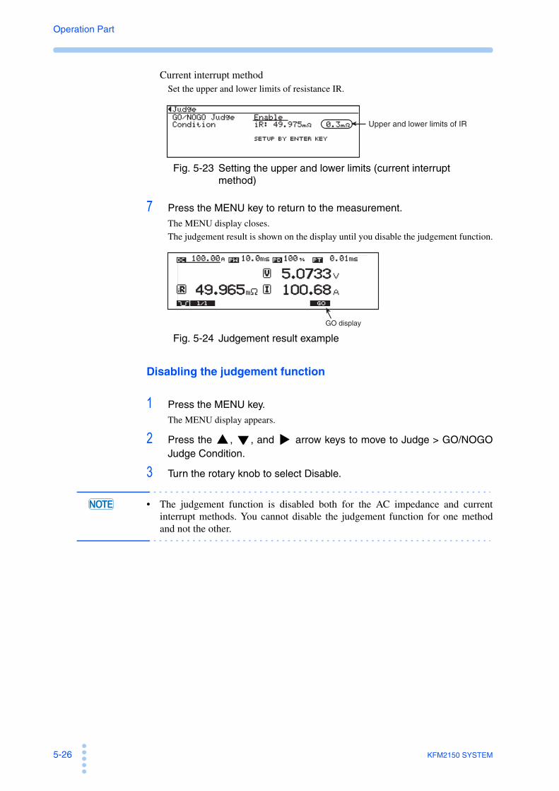
5-26 KFM2150 SYSTEM
Operation Part
Current interrupt methodSet the upper and lower limits of resistance IR.
Fig. 5-23 Setting the upper and lower limits (current interrupt method)
7 Press the MENU key to return to the measurement.
The MENU display closes.
The judgement result is shown on the display until you disable the judgement function.
Fig. 5-24 Judgement result example
Disabling the judgement function
1 Press the MENU key.
The MENU display appears.
2 Press the , , and arrow keys to move to Judge > GO/NOGOJudge Condition.
3 Turn the rotary knob to select Disable.
• The judgement function is disabled both for the AC impedance and currentinterrupt methods. You cannot disable the judgement function for one methodand not the other.
Upper and lower limits of IR
GO display

MaintenanceThis chapter describes maintenance of the KFM2150 includingcleaning, inspecting, calibrating, and troubleshooting.

6-2 KFM2150 SYSTEM
Operation Part
6.1 Cleaning and Inspection
Periodic cleaning and inspection are essential to maintain the initial performance ofthe KFM2150 system over an extended period.
• There is a possibility of death or injury from electric shock. Be sureto turn off the POWER switch and remove the power cord plugbefore performing maintenance work.
Cleaning the panels
If the panel needs cleaning, gently wipe the panel using a soft cloth with water-diluted neutral detergent.
• Do not use volatile chemicals such as benzene or thinner as they maydiscolor the surface, erase printed characters, cloud the display, and soon.
Inspecting the Power Cord
Check the power cord for breaks in the insulation and cracks or rattling of the plug.
• Tears in the insulation coating of the power cord may cause electricshock or fire. If a tear is found, stop using it immediately.
Replacing the backup battery
The KFM2150 backs up panel settings with the internal battery even when thepower is turned off. If the panel settings are different at the time the power is turnedoff and at the time the power is turned on again, the battery is already dead.
The battery life depends on the operating conditions. It is estimated about threeyears after the purchase. For battery replacement, contact your Kikusui agent ordistributor.
WARNING
CAUTION
WARNING

KFM2150 SYSTEM 6-3
Operation Part
Mai
nte
nan
ce
6
6.2 Calibration
The KFM2150 system is shipped after carrying out appropriate calibrations. Werecommend periodic calibration to maintain the performance over an extendedperiod.
The KFM2150 and the PLZ-4W Series are calibrated at the factory as a singlesystem. Therefore, the PLZ-4W Series must also be calibrated simultaneously. Fordetails, contact your Kikusui agent or distributor.
• Do not alter the variable resistor of the EXT CONT section on the PLZ-4W Series. There is a sticker attached to the variable resistor to preventaccidental operation. Altering the variable resistor will invalidate thecalibration of the impedance measurement system.
6.3 Troubleshooting
This section introduces troubleshooting measures. Typical symptoms are listed.Check whether any of the items below apply to your case. In some cases, theproblem can be solved quite easily.
If the remedy does not solve the problem or if your case does not match any of theitems, contact your Kikusui agent or distributor..
The KFM2150 system does not power up.
CAUTION
Symptom Check Items RemedyPage
The KFM2150 system does not operate when the POWER switch is turned on.
• Is the power cord disconnected from the power outlet?
• Is the power cord inserted correctly into the AC INPUT connector on the rear panel?
• Connect the power cord correctly.
• Power up the instruments in the correct order.
4-2
Response error occurs displaying the message “PLZ NO RESPONSE.”
• Is the wiring of the impedance measurement system correct?
• Wire the impedance measurement system correctly including the PLZ-4W Series.
4-24-16
System connection error occurs, and all the numeric displays are invalid (indicates “–”).
• Was the system powered up correctly?
• Are there system component instruments that are not turned on?
• Power up the instruments in the correct order.
4-2
System configuration error occurs displaying the message “PLZ FORMATION.”
• Are the system component instruments correct?
• Are the serial numbers of the system component instruments correct?
• Connect the correct system component instruments.
4-2
See

6-4 KFM2150 SYSTEM
Operation Part
Keys operation do not work correctly.
The KFM2150 system does not operate according to the settings. The measured values are unstable.
Symptom Check Items RemedyPage
Panel key operations are not functioned.
• Is LOCK shown in the status display?
• The panel operation is locked. Press the LOCK (SHIFT+LOCAL) key to release the lock.
4-16
• Is the RMT LED illuminated? • The KFM2150 system is being remotely controlled via the external interface. Press the LOCAL key to release remote control.
4-16
See
Symptom Check Items RemedyPage
The current does not flow immediately when the load is turned on.
• Is the soft start rising time shown in the status display?
• This is a normal behavior. The current will be set to the preset load current when the soft start rising time reaches zero.
5-8
The current is not cut off immediately when the load is turned off.
• Is the soft start falling time shown in the status display?
• This is a normal behavior. The load current will be set to zero when the soft start rising time reaches zero.
5-9
The settings entered from the menu are not applied.
• Did you turn off the POWER switch after changing the settings?
• Turn off the POWER switch after you change the settings. The settings are applied when the power is turned back on.
4-26
The measured values are unstable.
• Is there a large loop in the sensing wire?
• Twist the wires. A-14
• Is the CV mark shown in the display?
• Is the fuel cell voltage low?
• The KFM2150 switched from CC mode to CV mode. Decrease the load current.
4-10
The load turns off. • Is the fuel cell voltage low? • The undervoltage protection (PLZ4W UVP) is activated. Check the fuel cell.
4-12• Is the fuel cell voltage high? • The overvoltage protection (PLZ4W
OVP) is activated. Check the fuel cell.
• Is the polarity of the wiring to the fuel cell reversed?
• The reverse connection protection (PLZ4W REV) is activated. Check the fuel cell wiring.
• Is the air outlet of the PLZ-4W Series blocked?
• The overheat protection (PLZ4W OHP) is activated. Allow at least 20 cm between the air outlet and the wall. Do not place objects within 20 cm.
PLZ-4W Series
Operation Manual• Is the dust filter of the PLZ-4W
Series clogged?• The overheat protection (PLZ4W
OHP) is activated. Clean the dust filter.
• Is the voltage at the fuel cell sensing point low?
• The voltage sensing undervoltage protection (SENSE UVP) is activated. Check the fuel cell.
4-12
See

SpecificationsThis chapter describes the specifications of the KFM2150system.
Unless specified otherwise, the following specifications arebased on the setting and conditions
• Warm-up time: 30 minutes (with current flowing).• Temperature: 20 °C to 30 °C• Humidity: 20 %rh to 85 %rh • typ: A typical value. It does not guarantee the performance.• rdng: Indicates the read value.• rng: Indicates the range value.• f.s: Full scale

7-2 KFM2150 SYSTEM
Operation Part
7.1 Basic Performance
Bench top type
System model KFM2150 SYSTEM165-01A
KFM2150 SYSTEM660-01A
KFM2150 SYSTEM1320-02A
System component instruments
Impedance meter KFM2150
Electronic load unitPLZ164WA (1 unit) PLZ664WA (1 unit) PLZ664WA (2 units)
Rating
Operating voltage*1 0 V to 150 V 0 V to 150 V 0 V to 150 V
Current*2 33 A 132 A 264 A
Power*3 165 W 660 W 1320 W
Constant current mode
Selectable range (ranges H, M, and L)
H 0 A to 33 A 0 A to 132 A 0 A to 264 A
M 0 A to 3.3 A 0 A to 13.2 A 0 A to 26.4 A
L 0 A to 0.33 A 0 A to 1.32 A 0 A to 2.64 A
Resolution (ranges H, M, and L)
H 1 mA 10 mA 20 mA
M 0.1 mA 1 mA 2 mA
L 0.01 mA 0.1 mA 0.2 mA
Setting accuracy (ranges H, M, and L)
H and M ±(0.2 % of setting + 0.2 % of f.s), f.s: the full scale of the H range.
L ±(0.2 % of setting + 0.2 % of f.s), f.s: the full scale of the L range.
Ammeter display
Range H 0.0000 A to 33.000 A 0.0000 A to 132.00 A 0.0000 A to 264.00 A
M 0.0000 A to 3.3000 A 0.0000 A to 13.200 A 0.0000 A to 26.400 A
L 0.0000 A to 0.3300 A 0.0000 A to 1.3200 A 0.0000 A to 2.6400 A
Accuracy (ranges H, M, and L)
H and M ±(0.3 % of rdng + 0.3 % of f.s), f.s: the full scale of the H range.
L ±(0.3 % of rdng + 0.3 % of f.s), f.s: the full scale of the L range.
Constant voltage mode
Selectable range 15 V 0 V to 15.75 V
150 V 0 V to 157.5 V
Resolution (Range)
15 V 1 mV
150 V 10 mV
Voltmeter display
Range 10 V 0.0000 V to 9.9999 V
100 V 10.000 V to 99.999 V
150 V 100.00 V to 150.00 V
Accuracy All ranges ±(0.1 % of rdng+0.1 % of rng)

KFM2150 SYSTEM 7-3
Operation Part
Sp
ecif
icat
ion
s
7
*1 At the input terminal of the master unit under DC operation.*2 Under DC operation. When measuring the AC impedance, the measuring AC current is
superposed. The sum of the load current and the measuring AC current peak must not exceedthis value. For example, if the measuring AC current is set to 10% of the load current, the loadcurrent that you can specify is approximately 87 % of this value.
*3 Under DC operation. When measuring the AC impedance, the measuring AC current issuperposed. The power that is determined by the sum of the load current and the measuringAC current peak and the input voltage must not exceed this value. For example, if themeasuring AC current is set to 10% of the load current, the power that you can use as a loadis approximately 87 % of this value.
*4 If the product of the measurement frequency f (kHz) and measuring AC current I (Arms)exceeds 500 when measuring the AC impedance, the minimum operating voltage increasesby 0.15 V for every 100 units that the product exceeds 500.
System model KFM2150 SYSTEM1000-01
KFM2150 SYSTEM3000-02
System component instruments
Impedance meter KFM2150
Electronic load unitPLZ1004W (1 unit)
PLZ1004W (1 unit)PLZ2004WB (1 unit)
Rating
Operating voltage*1 1.5 V to 150 V 1.5 V to 150 V *4
Current*2 200 A 600 A
Power*3 1000 W 3000 W
Constant current mode
Selectable range (ranges H, M, and L)
H 0 A to 200 A 0 A to 600 A
M 0 A to 20 A 0 A to 60 A
L 0 A to 2 A 0 A to 6 A
Resolution (ranges H, M, and L)
H 10 mA 30 mA
M 1 mA 3 mA
L 0.1 mA 0.3 mA
Setting accuracy (ranges H, M, and L)
H and M ±(0.2 % of setting + 0.2 % of f.s), f.s: the full scale of the H range.
L ±(0.2 % of setting + 0.2 % of f.s), f.s: the full scale of the L range.
Ammeter display
Range H 0.0000 A to 200.00 A 0.0000 A to 600.00 A
M 0.0000 A to 20.000 A 0.0000 A to 60.000 A
L 0.0000 A to 2.0000 A 0.0000 A to 6.0000 A
Accuracy (ranges H, M, and L)
H and M ±(0.3 % of rdng + 0.3 % of f.s), f.s: the full scale of the H range.
L ±(0.3 % of rdng + 0.3 % of f.s), f.s: the full scale of the L range.
Constant voltage mode
Selectable range 15 V 0 V to 15.75 V
150 V 0 V to 157.5 V
Resolution (Range) 15 V 1 mV
150 V 10 mV
Voltmeter display
Range 10 V 0.0000 V to 9.9999 V
100 V 10.000 V to 99.999 V
150 V 100.00 V to 150.00 V
Accuracy All ranges ±(0.1 % of rdng+0.1 % of rng)

7-4 KFM2150 SYSTEM
Operation Part
Rack mount type
System model KFM2150 SYSTEM1980-03A
KFM2150 SYSTEM2640-04A
KFM2150 SYSTEM3300-05A
System component instruments
Impedance meter KFM2150
Electronic load unitPLZ664WA (3 units) PLZ664WA (4 units) PLZ664WA (5 units)
Rating
Operating voltage*1 0 V to 150 V*4
Current*2 396 A 528 A 660 A
Power*3 1980 W 2640 W 3300 W
Constant current mode
Selectable range (ranges H, M, and L)
H 0 A to 396 A 0 A to 528 A 0 A to 660 A
M 0 A to 39.6 A 0 A to 52.8 0 A to 66 A
L 0 A to 3.96 A 0 A to 5.28 A 0 A to 6.6 A
Resolution (ranges H, M, and L)
H 30 mA 40 mA 50 mA
M 3 mA 4 mA 5 mA
L 0.3 mA 0.4 mA 0.5 mA
Setting accuracy (ranges H, M, and L)
H and M ±(0.2 % of setting + 0.2 % of f.s), f.s: the full scale of the H range.
L ±(0.2 % of setting + 0.2 % of f.s), f.s: the full scale of the L range.
Ammeter display
Range H 0.0000 A to 396.00 A 0.0000 A to 528.00 A 0.0000 A to 660.00 A
M 0.0000 A to 39.600 A 0.0000 A to 52.800 A 0.0000 A to 66.000 A
L 0.0000 A to 3.9600 A 0.0000 A to 5.2800 A 0.0000 A to 6.6000 A
Accuracy (ranges H, M, and L)
H and M ±(0.3 % of rdng + 0.3 % of f.s), f.s: the full scale of the H range.
L ±(0.3 % of rdng + 0.3 % of f.s), f.s: the full scale of the L range.
Constant voltage mode
Selectable range 15 V 0 V to 15.75 V
150 V 0 V to 157.5 V
Resolution (Range)
15 V 1 mV
150 V 10 mV
Voltmeter display
Range 10 V 0.0000 V to 9.9999 V
100 V 10.000 V to 99.999 V
150 V 100.00 V to 150.00 V
Accuracy All ranges ±(0.1 % of rdng+0.1 % of rng)

KFM2150 SYSTEM 7-5
Operation Part
Sp
ecif
icat
ion
s
7
*1 At the input terminal of the rack under DC operation.*2 Under DC operation. When measuring the AC impedance, the measuring AC current is
superposed. The sum of the load current and the measuring AC current peak must not exceedthis value. For example, if the measuring AC current is set to 10% of the load current, the loadcurrent that you can specify is approximately 87 % of this value.
*3 Under DC operation. When measuring the AC impedance, the measuring AC current issuperposed. The power that is determined by the sum of the load current and the measuringAC current peak and the input voltage must not exceed this value. For example, if themeasuring AC current is set to 10% of the load current, the power that you can use as a loadis approximately 87 % of this value.
*4 If the product of the measurement frequency f (kHz) and measuring AC current I (Arms)exceeds 500 when measuring the AC impedance, the minimum operating voltage increasesby 0.45 V for every 100 units that the product exceeds 500.
*5 If the product of the measurement frequency f (kHz) and measuring AC current I (Arms)exceeds 500 when measuring the AC impedance, the minimum operating voltage increasesby 0.6 V for every 100 units that the product exceeds 500.
System model KFM2150 SYSTEM5000-03
KFM2150 SYSTEM7000-04
KFM2150 SYSTEM9000-05
System component instruments
Impedance meter KFM2150
Electronic load unit PLZ1004W (1 unit)PLZ2004WB (2 units)
PLZ1004W (1 unit)PLZ2004WB (3 units)
PLZ1004W (1 unit)PLZ2004WB (4 units)
Rating
Operating voltage*1 1.5 V to 150 V *5
Current*2 1000 A 1400 A 1800 A
Power*3 5000 W 7000 W 9000 W
Constant current mode
Selectable range (ranges H, M, and L)
H 0 A to 1000 A 0 A to 1400 A 0 A to 1800 A
M 0 A to 100 A 0 A to 140 A 0 A to 180 A
L 0 A to 10 A 0 A to 14 A 0 A to 18 A
Resolution (ranges H, M, and L)
H 50 mA 70 mA 90 mA
M 5 mA 7 mA 9 mA
L 0.5 mA 0.7 mA 0.9 mA
Setting accuracy (ranges H, M, and L)
H and M ±(0.2 % of setting + 0.2 % of f.s), f.s: the full scale of the H range.
L ±(0.2 % of setting + 0.2 % of f.s), f.s: the full scale of the L range.
Ammeter display
Range H 0.0000 A to 1000.0 A 0.0000 A to 1400.0 A 0.0000 A to 1800.0 A
M 0.0000 A to 100.00 A 0.0000 A to 140.00 A 0.0000 A to 180.00 A
L 0.0000 A to 10.000 A 0.0000 A to 14.000 A 0.0000 A to 18.000 A
Accuracy (ranges H, M, and L)
H and M ±(0.3 % of rdng + 0.3 % of f.s), f.s: the full scale of the H range.
L ±(0.3 % of rdng + 0.3 % of f.s), f.s: the full scale of the L range.
Constant voltage mode
Selectable range 15 V 0 V to 15.75 V
150 V 0 V to 157.5 V
Resolution (Range)
15 V 1 mV
150 V 10 mV
Voltmeter display
Range 10 V 0.0000 V to 9.9999 V
100 V 10.000 V to 99.999 V
150 V 100.00 V to 150.00 V
Accuracy All ranges ±(0.1 % of rdng+0.1 % of rng)

7-6 KFM2150 SYSTEM
Operation Part
7.2 Impedance measurement
Method AC impedance method(variable measuring AC current)
Current interrupt method(variable interrupt current parameter)
Measurement items R, X, |Z|, and θ IR (internal resistance)
Measurement condition settings Measuring frequency:14 points/decade (1.00, 1.26, 1.58, 2.00, 2.51, 3.00, 3.16, 4.00, 5.00, 6.00, 6.30, 7.00, 8.00, and 9.00) in the 10 mHz to 20 kHz range
Measurement interval: Fixed to 100 ms
Measuring AC current:0 % to 10 % (as a percentage of the load current in rms value)Resolution: 0.1 %
Pulse depth: 0 % to 100 % (as a percentage of the load current) with a resolution of 1 %.
Pulse width: 0.1 ms to 10.0 ms with a resolution of 0.1 ms.
Pulse transition time: 0.01 ms to 10.00 ms*1 with a resolution of 0.01 ms.
Impedance measurement: Display range and resolution
10 mΩ range 0.0000 mΩ to 9.9999 mΩ
100 mΩ range 10,000 mΩ to 99.999 mΩ
1 Ω range 100.00 mΩ to 999.99 mΩ
10 Ω range 1.0000 Ω to 9.9999 Ω
Phase angle -180.00 deg to 180.00 deg -
Measurement accuracy Measurement accuracy for R and X
The measurement AC current is less than or equal to 10 A:±(the value (%) in the attached table for the |Z| reading + the value in Note 1 of the
attached table)*2
The measurement AC current is greater than 10 A:±(the value (%) in the attached table for the |Z| reading + 3 (%) + the value in Note 1 of the
attached table)*2
±3 %When a 10 mΩ resistor is connected in series with the power supply and measurements are taken under the following conditions
Measurement conditions • Load unit terminal input voltage*3 :
1.5 V*4 or 0 V*5
• Short-circuit correction function: Enabled• Average count: 256 times
• Load wire length*6 : 2 m• Maximum value of the measuring current:
80 Arms*4 or 50 Arms*5
• Load unit terminal voltage: 5 V• Load current: 20 A• Pulse depth: 50 % (10 A)• Pulse width: 10 ms• Pulse transition time: 10 ms• Sampling position: 5 ms• Sampling region: 0.51 ms• Average count: 32 times
*1. The lower limit of the selectable range may be limited by a value greater than 0.01 ms depending on the rated current,pulse depth, and load current settings.
*2. Table 7-1 is used to look up the attached table containing the values for each system model.*3. Includes the conditions indicated in footnotes *1, *4, and *5 for the operating voltage rating in “7.1 Basic Performance.”*4. KFM2150 SYSTEM1000-01, 3000-02, 5000-03, 7000-04, and 9000-05*5. KFM2150 SYSTEM165-01A, 660-01A, 1320-02A, 1980-03A, 2640-04A, and 3300-05A*6. From the input terminal of the PLZ-4W Series slave unit for the bench top type and from the input terminal of the rack for
the rack mount type.

KFM2150 SYSTEM 7-7
Operation Part
Sp
ecif
icat
ion
s
7
Table 7-1 Reference to the values in the attached tables(%)
Determining the measurement accuracy (how to use the attachedtables)
Use Table 7-2 to determine the measurement accuracy of bench top type KFM2150SYSTEM165-01A. The values inside brackets indicate corresponding areas in Fig.7-1.
Example 1: Load current is 10 A [1], measuring AC current is 1 A [1],measuring frequency is 3 kHz [2], sensing terminal input voltage range is10 V [3], and impedance range is 10 mΩ [4].
Measurement accuracy = ±(4 % of the |Z| reading [5] + 0.3 mΩ [6])
* Measurement accuracy = ±(4 % of the |Z| reading + 0.3 mΩ)
Example 2: Load current is 30 A [1], measuring AC current is 3 A [1],measuring frequency is 3 kHz [2], sensing terminal input voltage range is10 V [3], and impedance range is 100 mΩ [7].
Measurement accuracy = ±(3 % of the |Z| reading [8])
* Measurement accuracy = ±(3 % of the |Z| reading). There is no value for Note 1.
Fig. 7-1 How to use the attached tables (excerpt from Table 4-2)
System type System modelAttached table
numberBench top type KFM2150 SYSTEM165-01A Table 7-2
KFM2150 SYSTEM660-01A Table 7-3KFM2150 SYSTEM1320-02A Table 7-4KFM2150 SYSTEM1000-01 Table 7-5KFM2150 SYSTEM3000-02 Table 7-6
Rack mount type KFM2150 SYSTEM1980-03A Table 7-7KFM2150 SYSTEM2640-04A Table 7-8KFM2150 SYSTEM3300-05A Table 7-9KFM2150 SYSTEM5000-03 Table 7-10KFM2150 SYSTEM7000-04 Table 7-11KFM2150 SYSTEM9000-05 Table 7-12
Table 4-2 KFM2150SYSTEM165-01A ( − indicates no specifications)
PLZ-4W Range (Measuring current)
Sensing terminal input voltage (Range)
Impe- dance Range
Measuring frequency (Hz) Note 1
Up to 126 158
to 3 k 3.16 k to 9 k
10 k to 20 k
H and M
(0.2 Arms or more)
0 V to 10 V (10 V)
10 m 5 4 7 9
100 m W 5 3 5 8
1 W 6 5 8 – 10 W 6 7 – –
10 V to 100 V (100 V)
10 m W – – – – 100 m W 7 5 7 10
1 W 8 7 8 – 10 W 8 9 – –
100 V to 150 V (150 V)
10 m – – – – 100 m W – – – –
1 W 10 10 12 – 10 W 10 – – –
0.3 m W W
W
[1]
[2]
[3] [4]
[5]
[6]
[7] [8]

7-8 KFM2150 SYSTEM
Operation Part
Attached tables for the AC impedance method (Table 7-2 to Table 7-12)
Table 7-2 KFM2150 SYSTEM165-01A (– denotes undefined)
Table 7-3 KFM2150 SYSTEM660-01A (– denotes undefined)
*1 Up to 6.3 kHz*2 Up to 1 kHz
PLZ-4W range
(Measuring current)
Sensing terminalinput voltage
(Range)
Impedancerange
Measuring frequency (Hz)
Note 1Up to 126
158 to 3 k
3.16 kto 9 k
10 k to 20 k
H and M
(0.2 Armsor higher)
0 V to 10 V(10 V)
10 mΩ 5 4 7 9 0.3 mΩ100 mΩ 5 3 5 8
1 Ω 6 5 8 –10 Ω 6 7 – –
10 V to 100 V(100 V)
10 mΩ – – – –100 mΩ 7 5 7 10
1 Ω 8 7 8 –10 Ω 8 9 – –
100 V to 150 V(150 V)
10 mΩ – – – –100 mΩ – – – –
1 Ω 10 10 12 –10 Ω 10 – – –
L
0 V to 10 V(10 V)
10 mΩ – – – –100 mΩ – – – –
1 Ω – – – –10 Ω – – – –
10 V to 100 V(100 V)
10 mΩ – – – –100 mΩ – – – –
1 Ω – – – –10 Ω – – – –
100 V to 150 V(150 V)
10 mΩ – – – –100 mΩ – – – –
1 Ω – – – –10 Ω – – – –
PLZ-4Wrange
(Measuring current)
Sensing terminalinput voltage
(Range)
Impedancerange
Measuring frequency (Hz)
Note 1Up to 126
158 to 3 k
3.16 kto 9 k
10 k to 20 k
H and M
(0.5 Armsor higher)
0 V to 10 V(10 V)
10 mΩ 3 2 3 4 0.3 mΩ100 mΩ 3 2 3 5
1 Ω 4 3 6*1 –
10 Ω 4 8*2 – –
10 V to 100 V(100 V)
10 mΩ 5 3 5 6 0.3 mΩ100 mΩ 5 3 5 8
1 Ω 6 5 8*1 –
10 Ω 6 9*2 – –
100 V to 150 V(150 V)
10 mΩ – – – –100 mΩ 9 6 9 –
1 Ω 12 9 – –10 Ω 12 – – –
L
(0.05 Arms or higher)
0 V to 10 V(10 V)
10 mΩ 3 2 3 4 0.3 mΩ100 mΩ 3 2 3 5
1 Ω 4 3 6*1 –
10 Ω 4 8*2 – –
10 V to 100 V(100 V)
10 mΩ – – – –100 mΩ 5 3 5 8
1 Ω 6 5 8*1 –
10 Ω 6 9*2 – –
100 V to 150 V(150 V)
10 mΩ – – – –100 mΩ – – – –
1 Ω – – – –10 Ω – – – –

KFM2150 SYSTEM 7-9
Operation Part
Sp
ecif
icat
ion
s
7
Table 7-4 KFM2150 SYSTEM1320-02A (– denotes undefined)
Table 7-5 KFM2150 SYSTEM1000-01 (– denotes undefined)
*1 Up to 6.3 kHz*2 Up to 1 kHz
PLZ-4Wrange
(Measuring current)
Sensing terminalinput voltage
(Range)
Impedancerange
Measuring frequency (Hz)
Note 1Up to 126
158 to 3 k
3.16 kto 9 k
10 k to 20 k
H and M
(1 Armsor higher)
0 V to 10 V(10 V)
10 mΩ 5 4 7 9 0.3 mΩ100 mΩ 5 4 7 10
1 Ω 8 7 – –10 Ω 8 – – –
10 V to 100 V(100 V)
10 mΩ 7 5 7 9 0.3 mΩ100 mΩ 7 5 7 10
1 Ω 8 7 – –10 Ω 8 – – –
100 V to 150 V(150 V)
10 mΩ – – – –100 mΩ 12 10 12 –
1 Ω 14 12 – –10 Ω 15 – – –
L
(0.1 Armsor higher)
0 V to 10 V(10 V)
10 mΩ 5 4 7 9 0.3 mΩ100 mΩ 5 4 7 10
1 Ω 8 7 – –10 Ω 8 – – –
10 V to 100 V(100 V)
10 mΩ – – – –100 mΩ 7 5 7 10
1 Ω 8 7 – –10 Ω 10 – – –
100 V to 150 V(150 V)
10 mΩ – – – –100 mΩ – – – –
1 Ω – – – –10 Ω – – – –
PLZ-4Wrange
(Measuring current)
Sensing terminalinput voltage
(Range)
Impedancerange
Measuring frequency (Hz)
Note 1Up to 126
158 to 3 k
3.16 kto 9 k
10 k to 20 k
H and M
(0.5 Armsor higher)
0 V to 10 V(10 V)
10 mΩ 3 2 3 4 0.3 mΩ100 mΩ 3 2 3 5
1 Ω 4 3 6*1 –
10 Ω 4 8*2 – –
10 V to 100 V(100 V)
10 mΩ 5 3 5 6 0.3 mΩ100 mΩ 5 3 5 8
1 Ω 6 5 8*1 –
10 Ω 6 9*2 – –
100 V to 150 V(150 V)
10 mΩ – – – –100 mΩ 9 6 9 –
1 Ω 12 9 – –10 Ω 12 – – –
L
(0.05 Armsor higher)
0 V to 10 V(10 V)
10 mΩ 3 2 3 4 0.3 mΩ100 mΩ 3 2 3 5
1 Ω 4 3 6*1 –
10 Ω 4 8*2 – –
10 V to 100 V(100 V)
10 mΩ – – – –100 mΩ 5 3 5 8
1 Ω 6 5 8*1 –
10 Ω 6 9*2 – –
100 V to 150 V(150 V)
10 mΩ – – – –100 mΩ – – – –
1 Ω – – – –10 Ω – – – –

7-10 KFM2150 SYSTEM
Operation Part
Table 7-6 KFM2150 SYSTEM3000-02 (– denotes undefined)
Table 7-7 KFM2150 SYSTEM1980-03A (– denotes undefined)
PLZ-4Wrange
(Measuring current)
Sensing terminalinput voltage
(Range)
Impedancerange
Measuring frequency (Hz)
Note 1Up to 126
158 to 3 k
3.16 kto 9 k
10 k to 20 k
H and M
(1.5 Armsor higher)
0 V to 10 V(10 V)
10 mΩ 6 6 9 10 0.3 mΩ100 mΩ 6 6 9 12
1 Ω 10 9 – –10 Ω 10 – – –
10 V to 100 V(100 V)
10 mΩ 9 7 9 10 0.3 mΩ100 mΩ 9 7 9 12
1 Ω 10 9 – –10 Ω 10 – – –
100 V to 150 V(150 V)
10 mΩ – – – –100 mΩ 14 12 – –
1 Ω 15 15 – –10 Ω – – – –
L
(0.15 Armsor higher)
0 V to 10 V(10 V)
10 mΩ 6 6 9 10 0.3 mΩ100 mΩ 6 6 9 12
1 Ω 10 9 – –10 Ω 10 – – –
10 V to 100 V(100 V)
10 mΩ – – – –100 mΩ 9 7 9 12
1 Ω 10 9 – –10 Ω 10 – – –
100 V to 150 V(150 V)
10 mΩ – – – –100 mΩ 12 12 – –
1 Ω 15 15 – –10 Ω – – – –

KFM2150 SYSTEM 7-11
Operation Part
Sp
ecif
icat
ion
s
7
Table 7-8 KFM2150 SYSTEM2640-04A (– denotes undefined)
Table 7-9 KFM2150 SYSTEM3300-05A (– denotes undefined)
PLZ-4Wrange
(Measuring current)
Sensing terminalinput voltage
(Range)
Impedancerange
Measuring frequency (Hz)
Note 1Up to 126
158 to 3 k
3.16 kto 9 k
10 k to 20 k
H and M
(2 Armsor higher)
0 V to 10 V(10 V)
10 mΩ 8 8 10 12 0.3 mΩ100 mΩ 8 9 10 12
1 Ω 10 10 – –10 Ω 15 – – –
10 V to 100 V(100 V)
10 mΩ 10 9 10 12 0.3 mΩ100 mΩ 10 9 10 12
1 Ω 12 10 – –10 Ω 15 – – –
100 V to 150 V(150 V)
10 mΩ – – – –100 mΩ 15 15 – –
1 Ω 15 15 – –10 Ω – – – –
L
(0.2 Armsor higher)
0 V to 10 V(10 V)
10 mΩ 8 8 10 12 0.3 mΩ100 mΩ 8 9 10 12
1 Ω 12 10 – –10 Ω 15 – – –
10 V to 100 V(100 V)
10 mΩ – – – –100 mΩ 10 9 10 12
1 Ω 12 12 – –10 Ω 15 – – –
100 V to 150 V(150 V)
10 mΩ – – – –100 mΩ 12 12 – –
1 Ω 15 15 – –10 Ω – – – –
PLZ-4Wrange
(Measuring current)
Sensing terminalinput voltage
(Range)
Impedancerange
Measuring frequency (Hz)
Note 1Up to 126
158 to 3 k
3.16 kto 9 k
10 k to 20 k
H and M
(2.5 Armsor higher)
0 V to 10 V(10 V)
10 mΩ 8 8 10 12 0.3 mΩ100 mΩ 8 9 10 12
1 Ω 10 10 – –10 Ω 15 – – –
10 V to 100 V(100 V)
10 mΩ 10 9 10 12 0.3 mΩ100 mΩ 10 9 10 12
1 Ω 12 10 – –10 Ω 15 – – –
100 V to 150 V(150 V)
10 mΩ – – – –100 mΩ 15 15 – –
1 Ω 15 15 – –10 Ω – – – –
L
(0.25 Armsor higher)
0 V to 10 V(10 V)
10 mΩ 8 8 10 12 0.3 mΩ100 mΩ 8 9 10 12
1 Ω 12 10 – –10 Ω 15 – – –
10 V to 100 V(100 V)
10 mΩ – – – –100 mΩ 10 9 10 12
1 Ω 12 12 – –10 Ω 15 – – –
100 V to 150 V(150 V)
10 mΩ – – – –100 mΩ 12 12 – –
1 Ω 15 15 – –10 Ω – – – –

7-12 KFM2150 SYSTEM
Operation Part
Table 7-10 KFM2150 SYSTEM5000-03 (– denotes undefined)
Table 7-11 KFM2150 SYSTEM7000-04 (– denotes undefined)
PLZ-4Wrange
(Measuring current)
Sensing terminalinput voltage
(Range)
Impedancerange
Measuring frequency (Hz)
Note 1Up to 126
158 to 3 k
3.16 kto 9 k
10 k to 20 k
H and M
(2.5 Armsor higher)
0 V to 10 V(10 V)
10 mΩ 8 8 10 12 0.3 mΩ100 mΩ 8 9 10 15*1
*1. Up to 10 kHz
1 Ω 10 10 – –10 Ω 15 – – –
10 V to 100 V(100 V)
10 mΩ 10 9 10 12 0.3 mΩ100 mΩ 10 9 10 15*1
1 Ω 12 10 – –10 Ω 15 – – –
100 V to 150 V(150 V)
10 mΩ – – – –100 mΩ 15 15 – –
1 Ω 15 – – –10 Ω – – – –
L
(0.25 Armsor higher)
0 V to 10 V(10 V)
10 mΩ 8 8 10 12 0.3 mΩ100 mΩ 8 9 10 15*1
1 Ω 12 12 – –10 Ω 15 – – –
10 V to 100 V(100 V)
10 mΩ – – – –100 mΩ 10 9 10 15*1
1 Ω 12 10 – –10 Ω 15 – – –
100 V to 150 V(150 V)
10 mΩ – – – –100 mΩ 12 12 – –
1 Ω 15 – – –10 Ω – – – –
PLZ-4Wrange
(Measuring current)
Sensing terminalinput voltage
(Range)
Impedancerange
Measuring frequency (Hz)
Note 1Up to 126
158 to 3 k
3.16 kto 9 k
10 k to 20 k
H and M
(3.5 Armsor higher)
0 V to 10 V(10 V)
10 mΩ 10 9 10 15 0.3 mΩ100 mΩ 10 9 10 –
1 Ω 12 – – –10 Ω 15 – – –
10 V to 100 V(100 V)
10 mΩ 12 10 12 15 0.3 mΩ100 mΩ 12 10 12 –
1 Ω 12 – – –10 Ω 15 – – –
100 V to 150 V(150 V)
10 mΩ – – – –100 mΩ 15 15 – –
1 Ω 15 – – –10 Ω – – – –
L
(0.35 Armsor higher)
0 V to 10 V(10 V)
10 mΩ 10 9 10 15 0.3 mΩ100 mΩ 10 9 10 –
1 Ω 12 15 – –10 Ω – – – –
10 V to 100 V(100 V)
10 mΩ – – – –100 mΩ 12 10 12 –
1 Ω 12 – – –10 Ω – – – –
100 V to 150 V(150 V)
10 mΩ – – – –100 mΩ 12 12 – –
1 Ω 15 – – –10 Ω – – – –

KFM2150 SYSTEM 7-13
Operation Part
Sp
ecif
icat
ion
s
7
Table 7-12 KFM2150 SYSTEM9000-05 (– denotes undefined)
PLZ-4Wrange
(Measuring current)
Sensing terminalinput voltage
(Range)
Impedancerange
Measuring frequency (Hz)
Note 1Up to 126
158 to 3 k
3.16 kto 9 k
10 k to 20 k
H and M
(4.5 Armsor higher)
0 V to 10 V(10 V)
10 mΩ 10 9 10 15 0.3 mΩ100 mΩ 10 9 10 –
1 Ω 12 – – –10 Ω 15 – – –
10 V to 100 V(100 V)
10 mΩ 12 10 12 15 0.3 mΩ100 mΩ 12 10 12 –
1 Ω 12 – – –10 Ω 15 – – –
100 V to 150 V(150 V)
10 mΩ – – – –100 mΩ 15 15 – –
1 Ω – – – –10 Ω – – – –
L
(0.45 Armsor higher)
0 V to 10 V(10 V)
10 mΩ 10 9 10 15 0.3 mΩ100 mΩ 10 9 12 –
1 Ω 12 15 – –10 Ω – – – –
10 V to 100 V(100 V)
10 mΩ – – – –100 mΩ 12 10 12 –
1 Ω 12 – – –10 Ω – – – –
100 V to 150 V(150 V)
10 mΩ – – – –100 mΩ 12 12 – –
1 Ω 15 – – –10 Ω – – – –

7-14 KFM2150 SYSTEM
Operation Part
7.3 Functions and General Specifications
Bench top type
System model KFM2150 SYSTEM165-01A
KFM2150 SYSTEM660-01A
KFM2150 SYSTEM1320-02A
Electronic load function
Operation mode*1 Constant current (CC) and constant voltage (CV) mode.
Remote interface GPIB, RS232C, or USB (connect the KFM2150 using one of the interfaces).
Protection functionSENSE UVP
Turns the load off and outputs an alarm status signal when the sensing terminal voltage reaches the setting (-2 V to 150 V).
PLZ-4WProtection functions available on the PLZ-4W Series (OVP, OPP, OHP, UVP, and REV). OPP and UVP can be set from the KFM2150.
Current monitor output Directly outputs the current monitor output of the PLZ-4W Series and directly outputs 10 V f.s (H/L range), 1 V f.s (M range), or the input of current sensing terminal 2.
Signal output Load on status signalPhotocoupler open-collector output. Output logic switchable.
Alarm status signal
Signal input Voltage input for impedance measurementVOLTAGE SENSING 1/2
DC input voltage and range
0 V to 150 V. 10 V, 100 V, and 150 V range (auto switching).
Input impedance Approx. 1 MΩ.
Isolation 250 V (between the chassis and LOW terminal).
Current signal input CURRENT SENSING 2
DC input voltage and range
0 V to 10 V
Input impedance Approx. 1 MΩ.
Isolation 250 V (between the chassis and LOW terminal).
Alarm signal input Low: 0 V and high: 5 V. Activates an alarm on a low level input. Turns the load off when an alarm is activated.
General specifications
Nominal input voltage 100 Vac to 240 Vac, 50 Hz/60 Hz, single phase.
Input voltage range 90 Vac to 250 Vac
Input frequency range 47 Hz to 63 Hz
Power consumption 550 VAmax. 1600 VAmax. 3100 VAmax.
Inrush current (typ.) 120 A. 120 A. 200 A.
Operating temperature range 0 °C to 40 °C.
Operating humidity range 20 %rh to 85 %rh (no condensation).
Storage temperature range -20 ° to 70 °C.
Storage humidity range 0 to 90 %rh (no condensation).
Operating conditions Indoor use, Overvoltage Category II.
Withstand voltage(for KFM2150 unit)
Between input and chassis: No abnormalities at 1500 Vac for 1 minute
Insulation resistance(for KFM2150 unit)
Between input and chassis: 500 Vdc, 30 MΩ or more
External dimensions See Fig. 7-2 and Fig. 7-4. See Fig. 7-2 and Fig. 7-5.
Weight Approx. 13.5 kg Approx. 22 kg Approx. 38 kg
Accessories Flat cable PC02-PLZ-4W: 1 pc. PC01-PLZ-4W: 1 pc. PC01-PLZ-4W: 2 pc.
RS232C cable, sensing wire, and power cord
Each 1 pc.
Wire that is 80 mm2 in size and approx. 30 cm in length
None 2 pcs.
CD-ROM 1 pc,

KFM2150 SYSTEM 7-15
Operation Part
Sp
ecif
icat
ion
s
7
System model KFM2150 SYSTEM1000-01
KFM2150 SYSTEM3000-02
Electronic load function
Operation mode*1 Constant current (CC) and constant voltage (CV) mode.
Remote interface GPIB, RS232C, or USB (connect the KFM2150 using one of the interfaces).
Protection functionSENSE UVP
Turns the load off and outputs an alarm status signal when the sensing terminal voltage reaches the setting (-2 V to 150 V).
PLZ-4WProtection functions available on the PLZ-4W Series (OVP, OPP, OHP, UVP, and REV). OPP and UVP can be set from the KFM2150.
Current monitor output Directly outputs the current monitor output of the PLZ-4W Series and directly outputs 10 V f.s (H/L range), 1 V f.s (M range), or the input of current sensing terminal 2.
Signal output Load on status signalPhotocoupler open-collector output. Output logic switchable.
Alarm status signal
Signal input Voltage input for impedance measurementVOLTAGE SENSING 1/2
DC input voltage and range
0 V to 150 V. 10 V, 100 V, and 150 V range (auto switching).
Input impedance Approx. 1 MΩ.
Isolation 250 V (between the chassis and LOW terminal).
Current signal input CURRENT SENSING 2
DC input voltage and range
0 V to 10 V.
Input impedance Approx. 1 MΩ.
Isolation 250 V (between the chassis and LOW terminal).
Alarm signal input Low: 0 V and high: 5 V. Activates an alarm on a low level input. Turns the load off when an alarm is activated.
General specifications
Nominal input voltage 100 Vac to 240 Vac, 50 Hz/60 Hz, single phase.
Input voltage range 90 Vac to 250 Vac
Input frequency range 47 Hz to 63 Hz
Power consumption 260 VAmax. 460 VAmax.
Inrush current (typ.) 120 A. 200 A.
Operating temperature range 0 °C to 40 °C.
Operating humidity range 20 %rh to 85 %rh (no condensation).
Storage temperature range -20 °C to 70 °C.
Storage humidity range 0 to 90 %rh (no condensation).
Operating conditions Indoor use, Overvoltage Category II.
Withstand voltage(for KFM2150 unit)
Between input and chassis: No abnormalities at 1500 Vac for 1 minute
Insulation resistance(for KFM2150 unit)
Between input and chassis: 500 Vdc, 30 MΩ or more
External dimensions See Fig. 7-2 and Fig. 7-5. See Fig. 7-2, Fig. 7-5, and Fig. 7-6.
Weight Approx. 21 kg Approx. 45 kg
Accessories Flat cablePC01-PLZ-4W: 1 pc.
PC01-PLZ-4W: 1 pc.PC02-PLZ-4W: 1 pc.
RS232C cable, sensing wire, and power cord
Each 1 pc.
Wire that is 80 mm2 in size and approx. 30 cm in length
None 2 pcs.
CD-ROM 1 pc.
*1. The KFM2150 controls the PLZ-4W Series using the external voltage control function. Functions such as operationmode switching, switching mode, and sequence that are available when the PLZ-4W Series is used by itself cannot beused.

7-16 KFM2150 SYSTEM
Operation Part
Rack mount type
System model KFM2150 SYSTEM1980-03A
KFM2150 SYSTEM2640-04A
KFM2150 SYSTEM3300-05A
Electronic load function
Operation mode*1 Constant current (CC) and constant voltage (CV) mode.
Remote interface GPIB, RS232C, or USB (connect the KFM2150 using one of the interfaces).
Protection functionSENSE UVP
Turns the load off and outputs an alarm status signal when the sensing terminal voltage reaches the setting (-2 V to 150 V).
PLZ-4WProtection functions available on the PLZ-4W Series (OVP, OPP, OHP, UVP, and REV). OPP and UVP can be set from the KFM2150.
Current monitor output Directly outputs the current monitor output of the PLZ-4W Series and directly outputs 10 V f.s (H/L range), 1 V f.s (M range), or the input of current sensing terminal 2.
Signal output Load on status signalPhotocoupler open-collector output. Output logic switchable.
Alarm status signal
Signal input Voltage input for impedance measurementVOLTAGE SENSING 1/2
DC input voltage and range
0 V to 150 V. 10 V, 100 V, and 150 V range (auto switching).
Input impedance Approx. 1 MΩ.
Isolation 250 V (between the chassis and LOW terminal).
Current signal input CURRENT SENSING 2
DC input voltage and range
0 V to 10 V.
Input impedance Approx. 1 MΩ.
Isolation 250 V (between the chassis and LOW terminal).
Alarm signal input Low: 0 V and high: 5 V. Activates an alarm on a low level input. Turns the load off when an alarm is activated.
General specifications
Nominal input voltage 200 Vac to 240 Vac, 50 Hz/60 Hz, single phase.
Input voltage range 180 Vac to 250 Vac
Input frequency range 47 Hz to 63 Hz
Power consumption 4600 VAmax. 6100 VAmax. 7600 VAmax.
Inrush current (typ.) 280 A. 360 A. 450 A.
Operating temperature range 0 °C to 40 °C.
Operating humidity range 20 %rh to 85 %rh (no condensation).
Storage temperature range -20 °C to 70 °C.
Storage humidity range 0 to 90 %rh (no condensation).
Operating conditions Indoor use, Overvoltage Category II.
Withstand voltage(for rack system)
Between input and chassis: No abnormalities at 1500 Vac for 1 minuteBetween input and load terminal: No abnormalities at 1500 Vac for 1 minute
Insulation resistance(for rack system)
Between input and chassis: 500 Vdc, 30 MΩ or moreBetween load terminal and chassis: 500 Vdc, 30 MΩ or more
External dimensions See Fig. 7-7.
Weight Approx. 170 kg Approx. 185 kg Approx. 200 kg
Accessories Load input terminal coverPower input terminal block cover
Each 1 pc. (comes attached)
CD-ROM 1 pc,
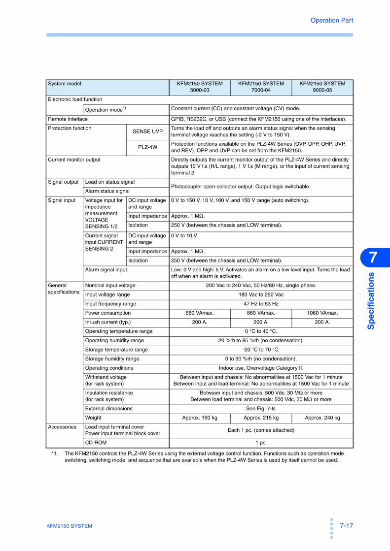
KFM2150 SYSTEM 7-17
Operation Part
Sp
ecif
icat
ion
s
7
System model KFM2150 SYSTEM5000-03
KFM2150 SYSTEM7000-04
KFM2150 SYSTEM9000-05
Electronic load function
Operation mode*1 Constant current (CC) and constant voltage (CV) mode.
Remote interface GPIB, RS232C, or USB (connect the KFM2150 using one of the interfaces).
Protection functionSENSE UVP
Turns the load off and outputs an alarm status signal when the sensing terminal voltage reaches the setting (-2 V to 150 V).
PLZ-4WProtection functions available on the PLZ-4W Series (OVP, OPP, OHP, UVP, and REV). OPP and UVP can be set from the KFM2150.
Current monitor output Directly outputs the current monitor output of the PLZ-4W Series and directly outputs 10 V f.s (H/L range), 1 V f.s (M range), or the input of current sensing terminal 2.
Signal output Load on status signalPhotocoupler open-collector output. Output logic switchable.
Alarm status signal
Signal input Voltage input for impedance measurementVOLTAGE SENSING 1/2
DC input voltage and range
0 V to 150 V. 10 V, 100 V, and 150 V range (auto switching).
Input impedance Approx. 1 MΩ.
Isolation 250 V (between the chassis and LOW terminal).
Current signal input CURRENT SENSING 2
DC input voltage and range
0 V to 10 V.
Input impedance Approx. 1 MΩ.
Isolation 250 V (between the chassis and LOW terminal).
Alarm signal input Low: 0 V and high: 5 V. Activates an alarm on a low level input. Turns the load off when an alarm is activated.
General specifications
Nominal input voltage 200 Vac to 240 Vac, 50 Hz/60 Hz, single phase.
Input voltage range 180 Vac to 250 Vac
Input frequency range 47 Hz to 63 Hz
Power consumption 660 VAmax. 860 VAmax. 1060 VAmax.
Inrush current (typ.) 200 A. 200 A. 200 A.
Operating temperature range 0 °C to 40 °C.
Operating humidity range 20 %rh to 85 %rh (no condensation).
Storage temperature range -20 °C to 70 °C.
Storage humidity range 0 to 90 %rh (no condensation).
Operating conditions Indoor use, Overvoltage Category II.
Withstand voltage(for rack system)
Between input and chassis: No abnormalities at 1500 Vac for 1 minuteBetween input and load terminal: No abnormalities at 1500 Vac for 1 minute
Insulation resistance(for rack system)
Between input and chassis: 500 Vdc, 30 MΩ or moreBetween load terminal and chassis: 500 Vdc, 30 MΩ or more
External dimensions See Fig. 7-8.
Weight Approx. 190 kg Approx. 215 kg Approx. 240 kg
Accessories Load input terminal coverPower input terminal block cover
Each 1 pc. (comes attached)
CD-ROM 1 pc,
*1. The KFM2150 controls the PLZ-4W Series using the external voltage control function. Functions such as operation modeswitching, switching mode, and sequence that are available when the PLZ-4W Series is used by itself cannot be used.

7-18 KFM2150 SYSTEM
Operation Part
7.4 Outline Drawing
Bench top type
Fig. 7-2 KFM2150 outline drawing
Fig. 7-3 KFM2151 outline drawing
MAX455
430MAX10
MAX
2027
0
MAX
330
88
MAX
105
Unit: mm
430
MAX435
270
MAX
5
MAX
285
44
MAX
60
Unit: mm

KFM2150 SYSTEM 7-19
Operation Part
Sp
ecif
icat
ion
s
7
Fig. 7-4 PLZ164WA outline drawing
Fig. 7-5 PLZ664WA and 1004W outline drawings
124
214.5
MAX
20
MAX
155
MAX 470400
MAX 30
Unit: mm
MAX 10
MAX 455
429.5
128
MAX
150
MAX 30
MAX 470
400
Unit: mm

7-20 KFM2150 SYSTEM
Operation Part
Fig. 7-6 PLZ2004WB outline drawing
MAX
150
128
429.5
MAX440550
MAX600
Unit: mm

KFM2150 SYSTEM 7-21
Operation Part
Sp
ecif
icat
ion
s
7
Rack mount type
Fig. 7-7 KFM2150 SYSTEM1980-03A, KFM2150 SYSTEM2640-04A, and KFM2150 SYSTEM3300-05A outline drawings
100
1200
570
(80)
1350
650
800 MAX75
(780
)
50
Unit: mm

7-22 KFM2150 SYSTEM
Operation Part
Fig. 7-8 KFM2150 SYSTEM5000-03, KFM2150 SYSTEM7000-04, and KFM2150 SYSTEM9000-05 outline drawings.
800
950
100
1200
570
(80)
1350
MAX75
(780
)
50
Unit: mm

Appendix

A-2 KFM2150 SYSTEM
A.1 Connection to External DevicesThe KFM2150 FC Impedance Meter, a component instrument of this system,contains terminals used to connect external devices on the rear panel. They are usedin the following three cases.
• When controlling an external electronic load unit.
• When connecting to an external current detector.
• When using status signal output such as load-on and alarm on an externalinstrument.
A.1.1 Controlling an External Load UnitThe KFM2150 FC Impedance Meter collectively controls the PLZ-4W Series. It canalso simultaneously control an external electronic load unit. The conditions forcontrolling the external electronic load unit are set using the menus.
Setting the Aux DC Load menu (the control conditions of theexternal electronic load unit)
Set this menu item when using an external electronic load unit in addition to thePLZ-4W Series.
Table A-1 Setting the control conditions of the external electronic load unit
1 Select MENU key > Configuration > DC Load > Load On Output toselect the logic of the load on/off control signal output of the externalelectronic load unit (low or high).The load on/off control signal output to the PLZ-4W Series is also changed to the samelogic. Note that the PLZ-4W settings are changed automatically by the KFM2150.
2 Select Configuration > Aux DC Load > Control to set the control voltage usedto supply the maximum load current of the external electronic load unit.The selectable range is from 0.00 to 10.50 V.
3 Select Configuration > Aux DC Load > Full Scale to set the maximumload current of the external electronic load unit.The selectable range is from 0 A to 3500 A.
4 Select Setup > Aux DC Load > Output to set the load current of theexternal electronic load unit.The selectable range is from 0 A to the load current set in step 3.
5 Turn off the POWER switch of the KFM2150 and then turn it back on.
The settings are fixed.
Menu item Conditions to be set
Configuration > DC Load > Load On Output Load on/off signal output
Configuration > Aux DC Load >
Control Control voltage used to supply the maximum load current of the external electronic load unit.
Full Scale Maximum load current of the external electronic load unit.
Setup > Aux DC Load > Output Load current of the external electronic load unit

KFM2150 SYSTEM A-3
App
ExampleSet the electronic load unit as follows:
• Control voltage used to supply the maximum load current of the externalelectronic load unit: 10 V
• Maximum load current of the external electronic load unit: 200 A
• Load current of the external electronic load unit: 110 AAs shown in Fig. A-1, the control voltage that the KFM2150 delivers is 5.5 V.
Fig. A-1 Aux DC Load control
Using the CONTROL TERMINAL
The control terminal is for an external electronic load unit other than the PLZ-4WSeries. Screwless terminals are used. Use AWG24 wires and remove 10 mm of thecovering from the tip of the wires.
Fig. A-2 Screwless terminals and wires used
Table A-2 CONTROL TERMINAL arrangement
Fig. A-3 AUX DCLOAD REF output
0 A0 V 5.5 V 10 V
Control
Load current
Output
200 A
110 A
Control voltage
Full Scale
AWG 24
STRIP-GAUGE 10 mm
Wire insertion hole
Insert the wire while holding down this section with the tip of a screwdriver.
Terminal number
Signal name Description
1 AUX DCLOAD REF Current setting signal output: 0 V to 10 V.*1
2 AUX DCLOAD COM Common for the current signal setting output.
3 LOAD ON/OFF CONT Load on/off control signal output.*2 ,*3
4 ALARM OUTAlarm output. Delivers a low level signal when an alarm
occurs on the KFM2150 or the PLZ-4W Series.*2
5 AUX LOAD STATUS COM Common for terminal number 3 and 4.
6 N.C. (No connection)
*1. Fig. A-3 shows an example.*2. Same logic as the PLZ-4W Series to the load on/off control signal.*3. Open collector output by a photocoupler. Maximum applied voltage: 30 V, maximum current: 5 mA.
1
2
+
−Twist
CONTROL TERMINAL
AUX DCLOAD REF
AUX DCLOAD COM
External electronic load unit
To the fuel cell

A-4 KFM2150 SYSTEM
A.1.2 Using Channel 2 of the CURRENT SENSING TerminalThe current signal of the impedance measurement is connected to the CURRENTSENSING terminal.
Channel 2 of the CURRENT SENSING terminal is used when connecting anexternal current detector.
Select MENU key > Setup > Input Select > Current Sensing to select channel 2.
The CURRENT SENSING terminal is insulated from the chassis. HIGHcorresponds to high potential, and LOW corresponds to low potential. The DC inputvoltage range is 0 V to 10 V, and the input impedance is approx. 1 MΩ .
A.1.3 J1 Connector
Table A-4The J1 connector used to connect to an external system. It is used to performinterconnected operation such as turning the load off on the electronic load unitusing commands from external equipment such as gas control equipment. Do notbundle the wires with other wires, and connect the wires to gas control equipment ora controller independently.
Do not bundle with the following types of wires
• Load wires of the electronic load unit.
• Sensing wires of the KFM2150.
• Wires to component fans or blowers and electromagnetic valve.
• AC power input wires of instruments
Fig. A-4 J1 and J2 connectors
• To disconnect the connector, remove the lock levers located on eitherside and pull the connector itself.
• Be sure to turn off the KFM2150 before attaching or removing theconnector.
Use a standard MIL 20-pin connector for connecting to the J1 connector.
Table A-3 shows the recommended connectors.
See
Pin number of the external control connector
J1
J2
121920
1219192020
CAUTION

KFM2150 SYSTEM A-5
App
• When using a flat cable, be sure to use a connector with a strain relief.
• To press-fit discrete wires or flat cables, be sure to use a special tool. For adescription of applicable cables and tools, see the relevant catalogs of connectormanufacturers.
Table A-3 Connectors compatible with the J1 connector
Table A-4 J1 connector pin arrangement
Manufacturer Product name Note
Omron XG5M-2032, XG5M-2035, or XG5S-1001 (2 pcs.) For discrete wires
Omron XG4M-2030 or XG4T-2004 For flat cables
KEL 6200-020-601 For flat cables
PinNo.
Signal name Description
1 IMONCurrent monitor output (IMON of the PLZ-4W Series).10 V f.s (H/L range) and 1 V f.s (M range).
2 UI1 General purpose input 1: TTL level.
3 IMON COMCommon for current monitor output. Save electrical potential as the LOW terminal of the CURRENT SENSING input.
4 N.C.Open-circuit pins for preventing malfunction due to incorrect connection. Do not connect anything to these pins.
5 N.C.
6 N.C.
7 UO1 General purpose 1: Open collector output.*1
8 UI2 General purpose input 2: TTL level.
9 UI3 General purpose input 3: TTL level.
10 ALARM IN External alarm input: TTL level. Low level indicates alarm.
11 UI4 General purpose input 4: TTL level.
12 A COM Common for the TTL level input.
13 LOAD ON STATUSLoad on status output. Delivers high or low signal when the load is on
on the load unit.*2 Open collector output by a photocoupler.*3
14 UO2 General purpose 2: Open collector output.*1
15 UO3 General purpose 3: Open collector output.*1
16 ALARM STATUS
Alarm status output. Delivers high or low signal when an alarm is
detected.*4
Open collector output by a photocoupler.*3
17 STATUS COM Common for status output.
18 UO4 General purpose 4: Open collector output.*1
19 N.C. Open-circuit pins for preventing malfunction due to incorrect connection. Do not connect anything to these pins.20 N.C.
*1. Maximum applied voltage: 50 V, maximum current: 100 mA.*2. Set the logic using MENU key > Configuration > DC Load > Load On Status. The setting
takes effect when the POWER switch is turned off and then turned back on.*3. Maximum applied voltage: 30 V, maximum current: 5 mA.*4. Set the logic using MENU key > Configuration > Alarm > Alarm Status. The setting takes
effect when the POWER switch is turned off and then turned back on.

A-6 KFM2150 SYSTEM
A.2 Factory Default Settings
The KFM2150 FC Impedance Meter, a component instrument of this system, isshipped with the settings shown in Table A-5.
Table A-5 Factory default settings
Item Setting
Measurement method AC impedance method
AC impedance method
Measuring frequency (FREQ) 20 kHz
Measuring AC current 10 %
Current interrupt method
Pulse width (WIDTH) 10.0 ms
Pulse depth (DEPTH) 100 %
Pulse transition time (TRNSN) 0.01 ms
Sampling start position 0.06 ms
Sampling region 0.030 ms
Average count (AVE) 1
DC current 0 A
Soft start rise time 0:00 s
Soft start fall time 0:00 s
Display (VIEW) Upper left R
Lower left X
Upper right Z
Lower right θScanner (KFM2151) Not used
Display color Blue
Alarm volume 64
Short-circuit correction function Disabled
Judgement function Disabled
VOLTAGE SENSING terminal Channel 1
CURRENT SENSING terminal Channel 1
Load current range of the PLZ-4W Series. HIGH
Voltage range of the PLZ-4W Series 150 V
CV mode transition voltage of the PLZ-4W Series 0 V
Voltage sensing undervoltage protection (SENSE UVP) -2 V
Voltage Sensing UVP Mask Time 4 s
Overpower protection (PLZ4W OPP) Maximum value of the PLZ-4W Series that are connected
Undervoltage protection (PLZ4W UVP) OFF
Remote control Interface setting GPIB
GPIB address 3
RS232C baud rate 19200 bps
RS232C data length 8 bits
RS232C stop bit 2 bits
RS232C acknowledge message Not used
External device connection
Load current of the external electronic load unit 0 A
Control voltage used to supply the maximum load current of the external electronic load unit
10.00 V
Maximum load current of the external electronic load unit
200 A
Alarm status output Hi
Load on/off control signal output. Hi
Load on status output Hi

KFM2150 SYSTEM A-7
App
A.3 Overview of the Fuel Cell and Evaluation System
A fuel cell is power generating equipment that produces power by a chemicalreaction between the fuel (hydrogen or methanol) and oxygen. The evaluationsystem operates the fuel cell and analyzes its characteristics. This sectionsummarizes the items related to the construction of an evaluation system.
A.3.1 Fuel Cell
Fuel cell types
There are various types of fuel cells such as phosphoric acid (PAFC), moltencarbonate (MCFC), solid oxide (SOFC), proton-exchange membrane fuel cell(PEFC or PEMFC), and direct methanol (DMFC). Each type has its owncharacteristics such as the operating temperature, main location of use, and outputcapacity. The following explanation mainly focuses on the PEFC and DMFC.
Fuel Cell Operation and Components
Fuel cells do not operate on fuel cell alone. They always require accompanyingdevices such as a device for supplying fuel, fuel pump, and fan. These devices areoften called components for the DMFC. The fuel cell system consisting of the fuelcell and components is needed to run the fuel cell as power generating equipment.
A.3.2 Installation Environment
Evaluation system and components
An evaluation system is needed to run the fuel cell and analyze itscharacteristics. Many of the evaluation systems have functions for controlling thefuel cell components including the pump, fan, bubbler (humidifier), heater, andelectromagnetic valve. This is because such functions are necessary forevaluating the optimal operating conditions, etc.
On the other hand, there are instruments that are needed in the evaluation systembut do not function as components in running the fuel cell such as an electronicload unit and impedance meter.
Construction of this system
The electronic load unit absorbs the power that the fuel cell generates andconsumes the power as heat during the fuel cell evaluation. The impedance metermeasures the impedance, which is one of the parameters used to check theoperating status of the fuel cell at that point. This system consists of theelectronic load unit and impedance meter.
Stable and sufficient power capacity
The fuel cell evaluation system may use significant amount of power incontrolling the components, gas flow and operating temperature controlequipment and electromagnetic valves. Electronic load units that have a built-inpower supply for operation (0 V type) also require large amount of power. It isimportant to ensure stable and sufficient power capacity in the installation of afuel cell evaluation system.

A-8 KFM2150 SYSTEM
Noisy environment
For such environment, turning on and off of the temperature control heater, theoperation of the electromagnetic valve may produce electrical noise. These typesof noise could be entered into the KFM2150 system via the AC power supply oras electromagnetic waves. It is important to install the KFM2150 system so thatthe system receives as little effect as possible from the noise.
For example, the AC power line connected to a control device that turns on/off alarge power supply should be of a separate system. In addition, those powercords need to be kept apart from the power cords of the KFM2150 system andnot bundled together. The same holds true for the power supply of the load andthe sensing wires.
Operating temperature of the fuel cell and used parts
In principle, impedance measurement of the KFM2150 system can be carried outon all fuel cell types. However, special preparation (for example, wiring theelectrodes for temperature measurement) is required for fuel cells that operate athigh temperatures such as the SOFC. The parts provided with the KFM2150 areassumed to be used with fuel cells that operate at low operating temperaturessuch as the PEFC and DMFC. Even in this case, check the temperature beforemaking actual measurements.
A.3.3 Precautions Concerning Installation
Precautions concerning the fuel cell
Fig. A-5 Fuel cell diagram
Polarity
A fuel cell always has positive and negative polarities. The polarities are alsocalled anode electrode and cathode electrode or fuel electrode and oxygenelectrode. The anode and cathode are negative and positive terminals,respectively. The fuel electrode and oxygen electrode are anode and cathode,respectively. The terminal where the electrons flow in is the positive terminal,and the terminal where the electrons flow out is the negative terminal.
Negative polarity Positive polarity
Anode Cathode
Fuel electrode Oxygen electrode
Electrode from which electrons flow out Electrode to which electrons flow in
+-
Fuel cell
Load cable
Voltage sensing
Anode Cathode
Fuel Oxygen
(Pos.)(Neg.)

KFM2150 SYSTEM A-9
App
Temperature
The operating temperature varies depending on the type of fuel cell. Thetemperatures in actual locations where the fuel cells are in operation can rangefrom several tens of degrees to several hundred degrees Celsius. The type ofterminal from which current is drawn and its temperature are importantparameters for selecting the wires used to connect the electronic load unit to thefuel cell.
Wires
The emitted voltage of a single fuel cell is 1 V to 1.2 V. However, large currentsin the order of 100 A can be drawn by increasing the cell area involved in thereaction. As explained later, the wires needed to draw out current in the order of100 A are quite large and thick.
Precautions concerning the electronic load unit
Polarity
The electronic load unit is a device that is connected to the fuel cell and absorbsthe energy that the fuel cell generates. The electronic load unit draws out aspecified current from the fuel cell and transforms the energy into heat inside theunit.
The electronic load unit also has positive and negative polarities. The positiveterminal is where the current flows in and is at a higher electric potential. Thenegative terminal is where the current flows out and is at a lower electricpotential.
The positive terminals of the electronic load unit and fuel cell are connectedtogether as well as the negative terminals. The electronic load unit will break ifyou reverse the connection.
Fig. A-6 Polarities of the electronic load unit
Rating
The electronic load unit has a voltage rating, current rating, and power rating.None of the ratings can be exceeded.
J1
J2
DC INPUT1000W
1.5-150V0-200A
Fuel cell
Fuel cell
+
–
+
–
PLZ-4W
Load wire
– +Load input terminal
–
+Electronic load unit input terminal

A-10 KFM2150 SYSTEM
A.4 Load WiresThe load wires conduct the output current from the fuel cell to the electronic loadunit. The wires for large currents used to connect to the fuel cell are quite differentfrom the wires you see in daily life. This section explains the structure and thecurrent capacity of the load wires.
A.4.1 Wire Structure
A.4.2 Current Capacity
Heat Generation
A wire has a maximum current that it can handle. Because the conductor of awire has resistance, power is consumed and heat is generated. The wire coveringhas an allowable temperature. If the temperature caused by the heat exceeds theallowable temperature, the wire may emit smoke or fire.
Current capacity and conductive cross-sectional area
The current capacity is determined by the covering material, temperaturecharacteristics of the conductor, etc. The temperature characteristics of theconductor are determined by the resistance of the conductor. The resistance ofthe conductor is mainly determined by its thickness. The thickness of theconductor is indicated by the cross-sectional area of the conductor. If several thinlines are bounded together, the thickness is represented by the sum of each cross-
sectional area. This cross-sectional area is indicated in units of mm2.
The current recommended by Kikusui shown in Table A-6 allows extra marginby taking into account the fact that the temperature increase in the wires isgreater when the wires are bound together and also how the electronic load unitis used.
The wires used in a household power strip are approximately 2 mm2 with anallowable current of 15 A. The allowable current of a wire with a cross-sectional
area of about 80 mm2 is 200 A. The diameter of this wire is 2 cm. This wire isquite heavy and weights approximately 1 kg/m.
Normally, the conductor of the loadwires is made of copper withinsulation covering on the outside (seeFig. A-7). For large currents, somewires come with conductors that arewoven (called earth cables, copperbraided flat wire, or flexible annealedcopper stranded wire). Because asingle copper wire is too hard to bend,many thin copper wires are normallytwisted and bound together.
Fig. A-7 Wire structure and conductive cross-sectional area
Normal wire
Copper braided flat conductor
Conductor
Conductor
Conductive cross-sectional area (nominal value)
Conductive cross-sectional area (nominal value)
Wire
Wire
Insulation
= Cross-sectional area of a strand × number of wires
= Cross-sectional area of a strand × number of wires

KFM2150 SYSTEM A-11
App
A.5 WiringThe wiring to connect the instruments is very important. You cannot simply connectthe instruments with wires. The wiring is the major factor for operating theevaluation system stably and attaining repeatability in measurements in varioustypes of environment described in section A.3.2, “Installation Environment.”
A.5.1 Connecting the Wires
Using crimping terminals
A cannon connector for large currents may be used to connect the wires to thefuel cell. In general, however, wires are connected using crimping terminals asan inexpensive but reliable method. A crimping terminal is connected to thestripped section of the wire by crushing the terminal with pressure so that theterminal and the conductor are combined. This crimping terminal is then screwedto the electrode of the fuel cell.
Crimping terminals that match to the conductor diameter of the wire are used. Acrimping tool is required to crimp the terminals. To crimp a wire with largeconductor diameter, a hydraulic crimping tool is required.
Fig. A-8 Crimping terminal
Contact resistance
In wiring, there is always has a section where the wire comes in contact with theelectrode. A contact resistance exists at the location where the terminal comes incontact with the electrode. Like the conductor resistance, this contact resistanceis also a large value that cannot be ignored.
Heavy wires
Thick wires are heavy. If the wire is used for rating of 200 A with length of 5 m.It is actually required of two wires for the positive and negative polarities, in thiscase we need for the total length of 10 m wire with a cross-sectional area of 80
mm2. Because a wire with a cross-sectional area of 80 mm2 weights 1 kg/m, thetotal weight becomes 10 kg. This may be heavier than the fuel cell.

A-12 KFM2150 SYSTEM
A.5.2 Wiring the Load Temperature at the contact section
Connect the wire so that the connected section is at a temperature lower than thevalue of the wire specifications taking into account the fuel cell type.
Current capacity
To determine the current capacity of the load wire, first consider how muchcurrent will be drawn from the fuel cell. Then, consider various cases such asnormal tests and boundary tests. From the results, determine the cross-sectionalarea of the wire needed to perform normal tests and the cross-sectional areaneeded to perform boundary tests by referring to Table A-6. For currents above
300 A, you must use multiple 150-mm2 wires or prepare a dedicated bus bar.
Length
Determine the length of the wires by considering the arrangement of the fuel celland electronic load unit. Take into account the weight of the wire and thelocation supporting the wires. Make the wire as short as possible to minimize theinductance.
Fig. A-9 Minimum area wiring and wires in contact with each other
Inductance
The inductance depends on the wiring. Inductance acts as the impedance for themeasuring AC signal. You must pay close attention to the inductance whenmeasuring the impedance of the fuel cell. Because two wires for the positive andnegative polarities are used, the wire inductance varies depending on how thewires are routed and bound together. These factors also require attention.
Wiring the KFM2150 system
Consider the wiring method by taking to the actual routing into consideration.Route the positive and negative wires in contact with each other, twisted with
Fuel cell
Contact resistance
Inductance
Electronic Load Unit
Voltage sensing
Bundle
In contact with each other
Minimize the
area created
by the wires C
C
C C
C

KFM2150 SYSTEM A-13
App
each other, or woven together. At the location where the wire is connected to thepositive and negative terminals of the electronic load unit, connect the wires withthe minimum length of separation.
In a rack mount type system, the wires may be quite thick and heavy. Routing thewires on the ground lowers the center of gravity and keeps the system stable, butthe wiring distance tends to be longer. If the wires are routed horizontally, thewiring to the fuel cell will be shorter, but the wires need to be supported formechanical stability. If the wires are raised for routing, the wires must besupported for stability. Routing the wires horizontally is advantageous in termsof measurements, but routing the wires on the ground is more mechanicallystable.
Wiring the fuel cell
Wires are connected in the same manner as the wiring of the KFM2150 system.The wires are connected to the positive and negative terminals with the minimumamount of separation at the contact points (minimum area wiring). Wires fromthe contact point to the actual electrodes of the fuel cell are also kept closelytogether or twisted together.
Do not move the load wires once they are routed. Moving the wires will degradethe repeatability of the impedance measurement values. In particular, never movethe wires if the short-circuit compensation function is used.
Load wires
Use wires of sufficient current capacity for the connection. Table A-6 indicatesthe nominal cross-sectional area and allowable current of wires.
Table A-6 Nominal cross-sectional area of wires and allowable currents
Nominal cross-sectional area
[mm2]AWG
(Reference cross-sectional area)
[mm2]
Allowable
current*1 [A](Ta = 30 °C)
*1. Excerpts from Japanese laws related to electrical equipment.
Current recommended by
Kikusui [A]
2 14 (2.08) 27 103.5 12 (3.31) 37 -5.5 10 (5.26) 49 208 8 (8.37) 61 30
14 6 (13.3) 88 5022 4 (21.15) 115 8030 2 (33.62) 139 -38 1 (42.41) 162 10050 1/0 (53.49) 190 -60 2/0 (67.43) 217 -80 3/0 (85.01) 257 200
100 4/0 (107.2) 298 -125 - - 344 -150 - - 395 300200 - - 469 -

A-14 KFM2150 SYSTEM
A.5.3 Wiring the sensing wires
Fig. A-10 Sensing wire environment
Wiring the KFM2150 system
Twist the sensing wires thoroughly or use shielded wires. Sensing wires areconnected to the sensing terminals of the KFM2150 or the sensing terminals onthe back of the rack on a rack mount system.
Wiring the fuel cell
At the fuel cell, connect the sensing wires to the point where you want tomeasure. For example, if you want to measure the impedance of a cell, connectto the point where you want to measure the cell. Correct measurements cannot bemade by simply connecting the sensing wires to the terminals of the electronicload unit or the terminals of the fuel cell where current is drawn even if thesepoints are connected electrically to the same points.
Connect the sensing wires in a well twisted condition to the measurement point(minimum area wiring). If this area is open, the measurement is affected, and theresults will not be correct. The sensing wires need to be connected directly to thepoint where you want to measure, but pay attention to the temperature at thatpoint. The temperature may be quite high depending on the fuel cell type. If thisis the case, special wires may be required.
Wiring the system
The fuel cell evaluation system consists of components such as a pump, heater,gas control equipment as well as electronic load unit and impedance meter.Wiring is not limited to the electronic load unit and impedance meter. Wires arealso connected to the pump and heater. Sensing wires are easily affected by thenoise generated by the wiring of other equipment.
Fuel cell
Voltage sensing
Pump
Heater
Load wire
Gas control
AC power supply
Heat

KFM2150 SYSTEM A-15
App
Separating the sensing wires from the load wires
Do not twist the sensing wires with the load wires. Measuring AC current isflowing through the load wires. If the sensing wires pass through the magneticfield created by the measuring AC current, noise is induced in the sensing wire,and correct measurements cannot be made. Separate the sensing wires from theload wires as much as possible, and lay them out through a route separate fromthe load wires to the fuel cell.
Shortest wiring
Like the load wires, route the sensing wires as short as possible. Noise may bepicked up if the wires are long.
Do not twist with other wires
Do not twist the load wires and sensing wires together. In addition, do not twistthe wires with the power lines of measuring instruments or other equipment suchas gas control equipment or signal lines. If you do, the sensing wires will pick upnoise and hinder correct and repeatable measurements. Furthermore, it maycause errors in the measuring instrument or other control equipment.

A-16 KFM2150 SYSTEM
A.6 What Is an Electronic Load Unit
An electronic load unit is a load unit constructed of electronic circuits. It canachieve characteristics that are not available in a resistive load. A load is a devicethat consumes the power that the fuel cell generates. Normally, a resistor isconnected, and the energy is consumed as heat. If a resistor is used as a load, thecurrent varies depending on the voltage, and the consumed power varies. This is notdesirable in an evaluation system.
A.6.1 Operation modes
An electronic load unit has the following typical operation modes.
CC (constant current) mode
CC mode allows a constant current to be run regardless of the voltage. Thecurrent value can be set in detail.
CV (constant voltage) mode
CV mode allows current to be run so that the voltage is kept constant. Thevoltage value can be set in detail.
CR (constant resistance) mode
CR mode allows a current to flow in proportion to the voltage. The resistance canbe set in detail.
The PLZ-4W Series Electronic Load Unit also has CC+CV and CR+CV modes.These modes are suitable for examining the discharge characteristics of the battery.The KFM2150 system uses the PLZ-4W Series in CC+CV mode.
CC+CV mode
The PLZ-4W Series normally operates in CC mode. If the fuel cell voltage dropsto a specified level, the PLZ-4W Series automatically switches to CV mode. Forexample, let’s assume we have a fuel cell with an open-circuit voltage of 10 Vthat drops to 9 V when 10 A of current flows and 7 V when 20 A flows. We donot know how much current flow at 8 V. In such case, if we use CC+CV modeand set the CV mode transition voltage to 8 V, the PLZ-4W operates in CC modeuntil the fuel cell voltage drops to 8 V. As the current is gradually increased andthe fuel cell voltage drops to 8 V, the PLZ-4W switches to CV mode and controlsthe current so that 8 V is maintained without allowing the current to exceed thespecified value. If the current is gradually decreased, the PLZ-4W automaticallyswitches to CC mode.
CR+CV mode
The PLZ-4W Series normally operates in CR mode. The mode switches to CV ifa specified voltage is reached.

KFM2150 SYSTEM A-17
App
Fig. A-11 Battery discharge (transition from CC mode to CV mode)
A.6.2 Operating Voltage Range
A certain voltage is required for the electronic load unit to operate.
This voltage is the minimum operating voltage. There are two types of PLZ-4WSeries depending on the operating voltage.
• Operating voltage range of 1.5 V to 150 V: PLZ-1004W and PLZ2004WB
• Operating voltage range of 0 V to 150 V: PLZ164WA and PLZ664WA
Operating voltage range of 0 V to 150 V (0 V type)
The type that operates from 0 V operating voltage range contains a power supplywith a voltage of approximately 1.5 V to allow it to operate even if the inputvoltage is 0 V. In other words, a voltage of approximately 1.5 V is applied to theinternal electronic load circuit, so that operation is not interrupted even if theinput voltage is 0 V. There is no need to worry about the internal power supplywhen using the electronic load unit, and the internal power supply cannot beused as a normal power supply. From the user point of view, either type ofelectronic load unit can be used in the same manner.
The voltage of a single fuel cell is approximately 1 V. If you need to evaluate asingle cell, you must use the PLZ164WA or PLZ664WA that allows you to setthe operating voltage to 0 V. Electronic load units that can be used from anoperating voltage of 0 V are sometimes called the 0 V type or the 0 V inputoperating voltage type. Likewise, electronic load units that can be used from anoperating voltage of 1.5 V are sometimes called the 1.5 V type or the 1.5 V inputoperating voltage type.
Load on and load off
An electronic load unit can run or stop the current as a load. “Turning the loadon” refers to the operation of enabling the current flow, and “turning the loadoff” refers to the operation of stopping the current.
Time
Voltage
0
V
Voltage or current
Current
CC mode CV mode
CV
CCI
VCV
CCI
: CV mode preset voltage
: CC mode preset voltage

A-18 KFM2150 SYSTEM
A.6.3 How to use CV mode and Remote Sensing
This system operates in CC+CV mode, in which the system automatically switchesbetween CC mode and CV mode. During normal operation, the system operates inCC mode, in which constant current runs independent of the voltage. If constantcurrent can no longer run in CC mode, the system switches to CV mode andprevents overcurrent from flowing by maintaining the preset voltage. However, ifthe running current is large, due to the voltage drop in the wires, a voltage higherthan the preset CV voltage will be maintained across the fuel cell output terminals.The PLZ-4W remote sensing feature can be used to compensate for this voltagedrop and switch to CV mode at the correct voltage.
Remote sensing terminals are on the rear panel of the PLZ-4W on the bench toptype and the rear panel of the rack on the rack mount type. When these terminals areconnected to the fuel cell output terminals, the system will switch to CV mode whenthe voltage across the fuel cell output terminals reaches the preset CV voltage. Thevoltage compensation provided by the remote sensing feature is up to 2 V for asingle line. In other words, if the voltage drop in the wires is greater than 2 V, thesystem will not operate at the correct preset CV voltage. In this situation, use wiresthat are sufficiently thick for the current and the shortest wires possible for theconnection.
The PLZ-4W displays the voltage at the sensing point and activates the protectivecircuit on the basis of this voltage. If you don't use the remote sensing function, thesensing point will be at the PLZ-4W load input terminal, and when the load inputterminal voltage reaches the preset CV voltage, the PLZ-4W will switch to CVmode. This will cause undesirable behavior. For example, while testing largecurrents on a single cell, the PLZ-4W will not be able to draw current even whenthere is sufficient cell voltage. This occurs because even when there is sufficient fuelcell voltage, when sensing is not used, the voltage at the PLZ-4W input terminalwill drop to the preset CV voltage causing the PLZ-4W to switch to CV mode, orthe voltage will drop 0 V preventing the PLZ-4W from drawing current.

KFM2150 SYSTEM A-19
App
A.7 I-V Characteristics Test
This section explains the points that need to be considered concerning thecharacteristics and wiring of the electronic load unit when performing I-Vcharacteristics tests.
Fig. A-12 Voltage drop diagram (example for 100 A)
A.7.1 Voltage Drop Caused by the Wires
Voltage drop occurrence
Because wires have conductor resistance, voltage drops occur even if wires ofsufficient cross-sectional area are used to connect the electronic load unit to thefuel cell (conductor resistance is never zero).
Voltage drop example
Let’s assume a fuel cell with an open-circuit voltage of 10 V. Because no currentis flowing through the electronic load, 10 V is applied across the input terminalsof the electronic load unit. Let’s assume that the fuel cell voltage falls to 9.5 Vwhen 100 A of current is drawn. At this point, the voltage applied to theelectronic load unit is not 9.5 V.
Let’s assume that the conductor resistance of the wire from the fuel cell to theelectronic load unit is 1 mΩ (corresponds about 2 m of wire with a cross-
sectional area of 38 mm2). Let’s also assume that the contact resistance betweenthe wire and the electronic load unit is 1 mΩ. What is the voltage drop when 100A of current is drawn?
• The voltage drop in the wire from the fuel cell to the positive terminal of theelectronic load unit is 100 A × 1 mΩ which is 0.1 V.
• The voltage drop in the wire from the negative terminal of the electronic loadunit to the fuel cell is 0.1 V.
Fuel cell Electronic Load Unit
Distance from the fuel cell electrode
Voltage drop
Vdp
Vdp = 0.2 V
Vdn
Vdn = 0.2 V
Vdz
Vdz = 9.1 VVplz
Vplz
E = 9.5 V
Battery voltage

A-20 KFM2150 SYSTEM
• In addition, the voltage drop due to the contact resistance between each wireand each input terminal of the electronic load unit is 0.1 V.
As a result, a total voltage drop of 0.4 V occurs. Therefore, the voltage at theinput of the electronic load unit is 9.1 V even though the voltage at the outputterminal of the fuel cell is 9.5 V. Note that the fuel cell voltage is not equal to theinput voltage of the electronic load unit.
Power loss and heating of the wires (example for 100 A)
Note that if there is a voltage drop of 0.1 V in the wire when a current of 100 A isflowing, 10 W of power is consumed by the wire as given by 0.1 V x 100 A.Likewise, 10 W is consumed in the other wire, and 10 W is consumed at eachcontact input terminal. This means that a total of 40 W is consumed. All thepower is converted to heat, and you can see that the temperature at the inputterminals and wires increases.
As the current increases, the voltage applied to the electronic load unit decreases.At the same time, the heat generated by the wires and contacts increases.
A.7.2 Operating Voltage of the Electronic Load Unitand Voltage Drop in the Wire
Operating voltage of the electronic load unit
The minimum operating voltage is 1.5 V for the 1. 5 V type and 0 V for the 0 Vtype. This value is defined at the input terminal. Taking the PLZ1004W (1.5 Vtype) for example, if there is 1.5 V at the input terminal, the PLZ1004W candeliver the rated current of 200 A. This does not mean that the PLZ1004W candeliver 200 A when the fuel cell voltage is 1.5 V.
Actual example of the operating voltage of the electronic load unit
If the fuel cell voltage is 1.5 V when 200 A of current is drawn in the example ofsection A.7.1, “Voltage Drop Caused by the Wires,” the voltage at the input ofthe electronic load unit ends up being 0.7 V, because a total voltage drop of 0.8 Voccurs due to the wires and contact resistance.
Because the minimum operating voltage at the input terminal of the PLZ1004Wis 1.5 V, current cannot flow at 0.7 V. In other words, a single PLZ1004W cannotrun up to 200 A of current from a fuel cell whose voltage is 1.5 V. For details onthe current that the PLZ1004W can run, see the operation manual of the PLZ-4WSeries.
Fig. A-13 Voltage drop diagram (example for 200 A)
Distance from the fuel cell electrode
Voltage drop
Vdp = 0.4 V
Vdn = 0.4 V
Vdz = 0.7 VVplzE = 1.5 V
Battery voltage

KFM2150 SYSTEM A-21
App
Operating voltage of a 0 V type electronic load unit
The PLZ664WA can run the rated current down to an input voltage of 0 V. Thisalso does not mean that the PLZ664WA can run the current until the fuel cellvoltage is 0 V. If the voltage drops due to the wires and contact resistance and thevoltage at the input terminals of the electronic load unit falls below 0 V (negativevoltage), the PLZ664W cannot run the current.
Fig. A-14 Voltage drop diagram (example for 0 V type)
A.7.3 Summary of the Required Test Conditions
Note the following items in the I-V characteristics tests of fuel cells in which thearea of a single cell is large and the current is large.
• If you do not minimize the voltage drop caused by the wires and contactresistance, the voltage at the input terminals of the electronic load unit may fallbelow the minimum operating voltage, and the desired current may not beobtained.
• The conductor resistance of a wire is determined by its cross-sectional area andlength. Therefore, the conductor used in the wiring must be as thick and short aspossible.
• The contact resistance at connection point can be reduced not only by fasteningthe screw with sufficient torque but also making the contact area large byfastening multiple screws.
• It may seem that increasing the voltage of the power supply built into theelectronic load unit and allowing current to flow even if the input voltagebecomes negative is a good idea. However, a voltage drop in the wire means thatthe wire is generating heat. You must use sufficiently thick and the shortest wiresto prevent the possibility of smoke emission or fire.
Distance from the fuel cell electrode
Voltage drop
Vdp = 0.4 V
Vdn = 0.4 V
Vdz = 0.7 VVplzE = 1.5 V
Battery voltage

A-22 KFM2150 SYSTEM
A.8 AC Impedance Characteristics Test
This section explains the points concerning the characteristics and wiring of theelectronic load unit that need to be considered when performing AC impedancecharacteristics tests.
A.8.1 Measurement Principles
Fig. A-15 Measurement principles
The principle used to measure the AC impedance is the Ohm's Law. The impedanceis equal to the voltage divided by the current. Therefore, in order to measure theimpedance, you can run a known, constant current through the object you want tomeasure, measure the voltage that is generated, and divide the voltage by thecurrent. However, the voltage and current here are of alternating current. Thus, thevoltage, current, and impedance contain information called magnitude (Z) andphase (θ). The information can also be represented as a real part and imaginary parton a complex plane. For impedance, the real part is the resistance (R), and theimaginary part is the reactance (X).
CC+CV mode
In the KFM2150 system, the PLZ-4W Series runs the value of constant currentwhich was set, and the KFM2150 measures the voltage that is generated at thefuel cell to derive the impedance.
The operation of constant current means that the PLZ-4W Series is normallyused in CC mode. CC+CV mode is used so that if the fuel cell can no longer runthe specified current, the PLZ-4W switches to CV mode to limit the current at agiven voltage.
CV mode
It is important to remember that if the PLZ-4W Series automatically switches toCV mode, a known constant current is no longer flowing. Consequently, theimpedance measurement result may not be correct. Therefore, the KFM2150system shows the PLZ-4W Series mode on the KFM2150 display so that you cansee the mode change if it does.
Fuel cellElectronic Load Unit
V I
V
ZV
IImpedance =

KFM2150 SYSTEM A-23
App
A.8.2 Wire Inductance
Superposed measuring AC current
An AC current is run through the fuel cell to perform AC impedancecharacteristics tests. The electronic load unit runs the current in the KFM2150system. This means that the measuring AC current is superposed on the DC loadcurrent in the wires.
Generation of inductance
You must pay attention to the wire inductance when the measuring AC current isflowing. The inductance produces reactance that oppose AC current. The unit isH (Henry). The reactance increases in proportion to the frequency of thealternating current.
Inductance example
The typical wire inductance is approximately 1 µH per meter when the positiveand negative wires are twisted together well. If the wire of each terminal(positive and negative) is divided into multiple wires, and the wires are twisted ina woven pattern or a bus bar is connected closely in contact, the inductance canbe lowered to approximately 0.5 µH/m. However, an inductance of 1 µH/m isessentially present in normal wiring. The inductance varies depending on thethickness and type of the wires, but it is basically 1 µH/m.
Calculation of reactance
Let’s assume that the electronic load unit and the fuel cell are connected using a1-m wire (1-m wires for positive and negative terminals twisted together). Thewire inductance is 1 µH from the equation 1 µH/m × 1 m.
The reactance is given by ωL (where ω is the angular frequency given byfrequency × 2 π and L is the inductance). The reactance is 0.628 mΩ at 100 Hz,6.28 mΩ at 1 kHz, 62.8 mΩ at 10 kHz, and 125 mΩ at 20 kHz. The reactancebecomes extremely large at high frequencies as compared to the conductorresistance of the wire.
Measuring AC current
Let’s assume we have a fuel cell with an open-circuit voltage of 10 V that dropsto 9.5 V when 100 A of current is run. We assume that the wire resistance to theload unit (DC resistance in this case) is 1 mΩ, the contact resistance at the inputterminal is also 1 mΩ, the wire length* is 2 m, and the inductance is 2 µH. TheDC voltage applied to the electronic load unit is 9.1 V (section A.7, “I-VCharacteristics Test”). Here, we superpose a measuring AC current of 10 Arms,which corresponds to 10 % of the 100-A DC current, to measure the ACimpedance of the fuel cell at 20 kHz.
* Length of the wire in one direction.
AC voltage
A DC voltage of 9.1 V is applied to the electronic load unit. What's the voltagewhen the measuring AC current is superposed? Because the wire inductance is 2µH, the reactance at 20 kHz is about 250 mΩ . Because 10 Arms of measuringAC current flows, a voltage of 2.5 Vrms appears as given by 250 mΩ × 10 Arms.

A-24 KFM2150 SYSTEM
Fig. A-16 Voltage drop caused by the inductance
A voltage of 9.1 Vdc and 2.5 Vrms is applied to the input of the electronic loadunit. This means that a peak voltage of 12.6 V and a bottom voltage of 5.6 V aswell as an AC voltage with a peak-to-peak voltage of approximately 7 V aroundthe DC voltage of 9.1 V are applied to the input (Fig. A-16).
A.8.3 Bottom Voltage
Bottom voltage and fuel cell voltage
Bottom voltage
You need to pay attention to the bottom voltage. The minimum operating voltageis defined on the electronic load unit. For the PLZ1004W, it is 1.5 V. Let’ assumethat the open-circuit voltage of the fuel cell is 6 V, and the voltage drops to 5.0 Vwhen 100 A is drawn given the same conditions. If an AC current that is 10 % of100 A is run, the peak voltage is 8.5 V and the bottom voltage is 1.5 V at theinput of the electronic load unit. If the fuel cell voltage drops or if a little morecurrent is run, the bottom voltage applied to the electronic load unit falls below1.5 V. This means that the specified measuring AC current cannot be run. If suchcondition actually occurs, the measuring AC current distorts, and correctmeasurements cannot be made (Fig. A-17).
12.6 V
5.6 V
9.1 V
0
9.5 V
100 A10 Arms20 kHz
1 m
1 m
1 m
1 m
9.1 V
V
Ω
Ω
Ω
Fuel cell Electronic Load Unit
250 m(2 μH)
Ω
Ω

KFM2150 SYSTEM A-25
App
Fig. A-17 Bottom voltage
Ensuring the bottom voltage
Parameters needed to ensure the bottom voltage are listed below.
• Fuel cell voltage.
• DC current run from the fuel cell (load current).
• Magnitude of the measuring AC current.
• Measurement frequency.
• Inductance (length and type of wires).
The wire inductance is pretty much determined by its length. To measure ACimpedance at high frequency, the wires must be connected at the shortest length.
Required fuel cell voltage
Table A-7 shows the fuel cell voltage that is required to keep the voltage at theelectronic load unit from falling below the minimum operating voltage (bottomvoltage) according to the wire length and measuring current. The figures aregiven by frequencies. Use them as guidelines. The measuring AC current isassumed to be an rms value corresponding to 10 % of the DC current (loadcurrent) and does not take into account the voltage drop caused by the DCcurrent. The electronic load type is assumed to be a 0 V type.
As shown in Table A-7, wires must be shortened for AC impedancemeasurements of fuel cells with large currents. It can be seen that if the currentof a single cell is large, measurement at high frequencies is difficult even if thewire length is less than 1 m.
(a) (b)
Vbot: Bottom voltage
12.6 V
5.6 V8.5 V
1.5 V
9.1 V
5.0 V
Vbot
0
5.4 V
100 A10 Arms20 kHz
1 m
1 m
1 m
250 m(2 μH)
1 m
5.0 V
V
Fuel cell Electronic Load Unit
250 m(2 μH)
ΩΩ
ΩΩ
Ω
Ω

A-26 KFM2150 SYSTEM
One method is to measure using the smallest possible measuring current.However, a certain level of measuring current is needed to measure small ACimpedance with high repeatability. You must also consider the upper limit of themeasurement frequency.
How to view the table
1 Select the DC current (load current).
(Example) 100 A
2 Select the measurement frequency.
(Example) 10 kHz
3 Select the wire length. The cross point of the wire length and themeasurement frequency is the fuel cell voltage that you aredetermining.(Example) The cross point between a wire length of 2 m and 10 kHz is 1.776 V.
Table A-7 Required fuel cell voltage (V)
DC current (A)
Measuring frequency (Hz)
Wire length*1 (m)
*1. Length of the wire in one direction.
1 2 5 10
10
100 0.001 0.002 0.004 0.009
1 k 0.009 0.018 0.044 0.089
3 k 0.027 0.053 0.133 0.266
10 k 0.089 0.178 0.444 0.888
20 k 0.178 0.355 0.888 1.776
20
100 0.002 0.004 0.009 0.018
1 k 0.018 0.036 0.089 0.178
3 k 0.053 0.107 0.266 0.533
10 k 0.178 0.355 0.888 1.776
20 k 0.355 0.710 1.776 3.552
50
100 0.004 0.009 0.022 0.044
1 k 0.044 0.089 0.222 0.444
3 k 0.133 0.266 0.666 1.332
10 k 0.444 0.888 2.220 4.440
20 k 0.888 1.776 4.440 8.880
100
100 0.009 0.018 0.044 0.089
1 k 0.089 0.178 0.444 0.888
3 k 0.266 0.533 1.332 2.664
10 k 0.888 1.776 4.440 8.880
20 k 1.776 3.552 8.880 17.760
200
100 0.018 0.036 0.089 0.178
1 k 0.178 0.355 0.888 1.776
3 k 0.533 1.066 2.664 5.328
10 k 1.776 3.552 8.880 17.760
20 k 3.552 7.104 17.760 35.520

KFM2150 SYSTEM A-27
App
Increasing bottom voltage
Product of the measurement frequency and measuring current
The minimum operating voltage of the electronic load unit varies depending onvarious conditions. The minimum operating voltage of the PLZ1004W andPLZ664WA are 1.5 V and 0 V, respectively.
However, if the product of the measurement frequency (kHz) and the measuringcurrent (Arms) exceeds 500, the minimum operating voltage increases. Theamount of increase varies depending on the model. For example, we will look atKFM2150 SYSTEM5000-03. This system allows up to 1000 A of rated current.
If you run a DC current of 500 A, and set the measuring current to 5 % which is25 Arms. If the measurement frequency is 20 kHz, the product of themeasurement frequency and the measuring current is 20 × 25 which is 500. Theminimum operating voltage up to this point is 1.5 V.
If you set the measuring current to 6 %, the measuring current is 30 Arms. In thiscase, the product of the measurement frequency and the measuring current is 20× 30 which is 600. Because the minimum operating voltage increases by 0.45 Vper 100 if 500 is exceeded, the minimum operating voltage is 1.5 V + 0.45 V =1.95 V.

A-28 KFM2150 SYSTEM
A.9 Impedance Measurement Tests Using the Interrupt Method
The current interrupt method allows the ohmic resistance of the electrochemical/electrical circuit (also called solution resistance and membrane resistance) to bedetermined. It is a value that is read from the voltage waveform when the current isinterrupted.
Fuel cells operate as batteries by the chemical reaction that takes place at theboundary face of the electrode and electrolyte. This reaction can be represented asan equivalent circuit. There are many equivalent circuits that have been devised, butthe circuit shown in Fig. A-18 is often used. Here, R1 is the ohmic resistance of theelectrochemical/electrical circuit, R2 is the resistance to charge transfer at theelectrolyte/electrode interface, and C is called the electric double layer capacitance.In the explanation below, we assume that the characteristics of the fuel cell can berepresented by this equivalent circuit.
Fig. A-18 The simplest equivalent circuit of a fuel cell
Conventional current interrupt method
In the current interrupt method, the load current i(t) of Fig. A-18 is varied in a steppattern shown in Fig. A-19, and the ratio of the amount of change at the sectionwhere the waveform of the voltage across the output terminals of the fuel cell v(t)jumps abruptly (the V section in Fig. A-19) versus the amount of change of currentat the corresponding point is determined. This value is assumed to be the ohmicresistance of the electrochemical/electrical circuit R1.
Fig. A-19 Conventional and actual interrupt current waveform
R1R2
E
Voltage v(t) Load current i(t)
C
I
i(t)
V = I*R1
v(t)
I
i(t)
V=?
v(t)
(a) Conventional (b) Actual

KFM2150 SYSTEM A-29
App
However, in the actual measurement, if load current i(t) is varied as shown in Fig. A-19 (a), the voltage response across the output terminals is as shown in Fig. A-19 (b)in most cases due to various effects such as the wire inductance.
Because the amount of change where the voltage response jumps (the V section inFig. A-19 (b)) is unclear in this condition, the determination of ohmic resistance ofthe electrochemical/electrical circuit R1 from the ratio against the amount of changeof current is difficult.
Technical Issues
• In the current interrupt method, the section where the voltage jumps can be readmore clearly as the speed of the current interrupt is made faster (the time until thecurrent is cut off is shortened). However, in reality, the voltage waveform isdistorted as shown in Fig. A-19 (b) due to the wire inductance.
• If the ohmic resistance of the electrochemical/electrical circuit is determined inthis condition, the value is not stable and carries no meaning as data.
• Because the wire length cannot be made zero, we must expect the waveform todistort to a certain extent due to the effects of inductance.
• Decreasing the speed of the current interrupt (making the time until the current iscut off longer) is effective in suppressing the waveform distortion if a certainlevel of inductance exists.
• In this case, the waveform distortion is decreased as shown in Fig. A-19 (a). Butbecause the change is gradual, the section where the voltage jumps becomesunclear. If the ohmic resistance of the electrochemical/electrical circuit isdetermined in this condition, the value ends up being different from the valuewhen the transition speed is fast.
A.9.1 Current Interrupt Method on the KFM2150
The KFM2150 provides the following three parameters to accommodate theconflicting issues given in “Technical Issues”.
• TRNSN that changes the current transition speed
An independent key is provided on the panel as a parameter setting for theinterrupt method. It is shown as PT on the display. This parameter sets the timeuntil the current is cut off.
• Position for reading the voltage waveform
• Region for reading the voltage waveform
These parameters are set using the MENU key. These parameters specify whichsection of the voltage waveform is to be read and used in the calculation.
Fig. A-20 shows the locations of the voltage waveform that are designated by thePosition and Region parameters.
• Position is the time that has elapsed since the completion of the currentinterrupt. It is the start point for reading the voltage waveform.
• Region specifies which range of the waveform is to be read from the start point.
The KFM2150 calculates the intended ohmic resistance of the electrochemical/electrical circuit (the value calculated by the ratio of the amount of change in the

A-30 KFM2150 SYSTEM
current to the amount of change in the voltage when the interrupt speed is fast andthe voltage waveform is not distorted) based on the waveform data in the specifiedregion. We will not go into the details of the calculation, but it basically uses linearapproximation of the data in the specified region.
Fig. A-20 Current waveform and the corresponding voltage response waveform across the fuel cell terminals
Characteristics of the three parameters
How should we select the three parameters, TRNSN (hereafter written as PT),Position, and Region? To calculate the intended ohmic resistance of theelectrochemical/electrical circuit, we should set PT to the smallest value,Position to zero, and Region to the smallest value. If a constant, stable value canbe obtained using these parameter values, this is the best data. However, it ishighly unlikely that a stable value can be obtained in this way due to the voltagewaveform distortion caused by the wire inductance.
The current interrupt method adopted by the KFM2150 varies the current in aramp pattern to I = PD over time (PT1) and estimates ohmic resistance of theelectrochemical/electrical circuit R1 from the transient response of the voltage.The reason for employing such method is to perform measurements bysuppressing the ringing in the voltage response as shown in Fig. A-19 (b).
Points in setting the parameters
The three parameters roughly have the following effects.
• PT suppresses the waveform distortion (called ringing) caused by the wireinductance.
• Position prevents the effect of the waveform distortion from being received.
• Region reduces the waveform noise.
These parameters need to be selected appropriately according to the wiringenvironment of the test, test conditions, and the characteristics of the fuel cell.Normally, once the parameter values are set, there is no need to change them by agreat amount.
i(t)
v(t)
t = 0t = 0
PT1
I = PD
Position
Region
Change the interrupt speed

KFM2150 SYSTEM A-31
App
Pulse transition time PT
Fig. A-21 Pulse transition time PT1 and ringing
Minimizing the effects of wiring
First, adjust the PT to minimize the waveform distortion caused by the effects ofwiring. You must also take all possible measures to reduce the inductance suchas twisting the load wires thoroughly and making them short according toメWiring モ on page A-11 .
Checking the effects of the inductance
The best way to reduce the inductance is to observe the voltage waveform of thefuel cell directly by the instrument such as oscilloscope. If you do not have anoscilloscope or the waveform cannot be observed because it is buried in noise,you can use the option for checking the waveform in the application softwareprovided.
PT setting and waveform distortion
If you decrease the PT, the waveform distortion increases. You can probably seethat the distortion decreases as the PT is increased. If the current to beinterrupted is large (approximately 50 A or more) or the wiring is long(approximately several meters or longer), setting the PT to the minimum value of0.01 ms will cause the waveform distortion to be too large. This may damage theelectronic load unit or cause an alarm. Thus, set the PT around 1 ms to view thewaveform.
Selecting the PT value
Select a PT value so that the waveform distortion (ringing) disappears. However,you cannot set the PT so large that the point where there is a clear distinction inthe waveform slope is no longer discernible. In such case, select the PT thatcauses the waveform distortion to settle in the shortest possible time even ifringing is present.
If the waveform cannot be observed
If you cannot observe the waveform, set the PT to the largest value (10.00 ms). Itis possible to select a value that is highly likely to be a good value using themethod explained later. However, we recommend that you check the waveformto prevent unexpected results.
i(t)
v(t)
PT1

A-32 KFM2150 SYSTEM
Setup procedure (example)
If you know in advance the value of PT that results in small voltage waveformdistortion (ringing), use that value and start from step 6 . If you cannot observer thewaveform, set the PT to the maximum value of 10.00 ms, and start from step 1 .
1 Set the Position value to the minimum 0.00 ms and Region to themaximum 0.510 ms.
2 Set the depth of the interrupt current and the interrupt pulse width.
It is easier to select the parameters by setting the interrupt pulse width as long aspossible (maximum setting of 10.00 ms).
3 Start the impedance measurement using the interrupt method.
If the IR value is unstable or a negative value appears
4 Set the average count to around 8.
If the value is still unstable or a negative value appears, you must review themeasurement environment such as making the wires shorter.
If the IR value is stable
5 Gradually decrease the PT value.
Check the location where the value was displayed changes drastically from the initialnumber (location where the value increases or decreases drastically or goes negative).Decrease the PT further and see if another drastic change in the value occurs. Ifanother drastic change is found, set the PT value to the value immediately before thechange. Otherwise, set the PT back to the value where the first drastic changeoccurred.
6 Set the Position value to 9.99 ms. Set the Region value to the maximum0.510 ms.
7 Start the impedance measurement using the interrupt method.
Remember the IR value that is displayed.(It should be different from the valuedisplayed in step 3 .)
8 Gradually decrease the Position value and find the place where the IRvalue is minimum.If the value decreases smoothly down to 0.00 ms, leave the Position value at 0.00 ms.
9 Decrease the Region value stepwise.
The IR value changes by a small amount while the fluctuation in the value increases. Ifthe fluctuation of the value is large, set the Region value back to a larger valuestepwise. You can also increase the average count. The fluctuation of the valuedecreases by increasing the average count. Increase the average count within thepossible range and set the Region value to a smaller value.
10 Decrease the PT value by a small amount.
If the IR value changes drastically, repeat the steps from step 6 . If the IR value doesnot change drastically, the parameter setting is tentatively complete. Check that the IRvalue does not change drastically when the PT is increased or decreased by a smallamount.

KFM2150 SYSTEM A-33
App
If you change the measurement conditions (the depth and width of the current interruptor load current), keep the Position and Region values and increase or decrease the PTto find a stable location.If the IR value is stable, the parameters can be used without further changes. If not,redo the settings from step 6 , because the IR value may be affected by the wiring.

A-34 KFM2150 SYSTEM
A.10 KFM2151 FC Scanner (Option)
A.10.1 Overview of the Scanner System
The KFM2151 FC Scanner has 32 channels of voltmeters and 32 channels of lineselector functions. By using the line selectors along with the KFM2150 FCImpedance Meter, each cell of a stack can be scanned to measure the impedance.
Scanning function
The 32-channel voltmeter section repeats the operation of reading of 32 channelsof voltage every second. Because overvoltage protection (OVP) andundervoltage protection (UVP) can be set on each channel, the KFM2151 can beused as a cell monitor.
The line selector function can be used independently of the voltmeter at the sametime. The voltage of all channels can be monitored even while being connectedto the KFM2150 to determine the impedance of a given cell.
Using the KFM2151 FC Scanner
1 Select MENU key> Configuration > Option > Scanner to select Enable.
If you disconnect the KFM2151 from the KFM2150, be sure to disable this item.Otherwise, the KFM2150 will not operate.
2 Select Setup > Input Select > Voltage Sensing to select channel 2.
3 Turn off the POWER switch of the KFM2150 and then turn it back on.
The scanner display ( ) appears on the KFM2150 enabling the use of the KFM2151.

KFM2150 SYSTEM A-35
App
A.10.2 Notes on Setting the Scanner System
Fig. A-22 Check points
The numbers in brackets (1 to 5) used in the following tables correspond to thenumbers indicated in Fig. A-22.
When using the FC scanner
The scanner icon is not displayed.
If the scanner function is enabled and the KFM2150 is connected to the KFM2151, theKFM2150 panel shows the scanner icon. The icon is displayed only if the KFM2150connection cable is connected. If the KFM2151 is not turned on, the icon is notdisplayed even if the KFM2150 connection cable is connected.
The measured values on the KFM2150 are odd.
The KFM2150 panel does not indicate which voltage sensing input (input 1 or input 2)is being used.
KFM2151KFM2150 PLZ-4W
POWER
VOLTAGESENSING
Input 1
Input 2
×10
×1Load on/off
POWER switch
Connect
Select the voltage sensing input(Input 1 or input 2)
Set whether to use the scanner
Yes
No
IN/OUT
OPTION
OPTION
KFM2150 connection cable
[1]
[2]
[3]
[4]
[5]
Symptom Points to check Remedy
The scanner icon is not displayed even if the scanner function is enabled [1].
• [5] KFM2150 connection cable• [4] Is the POWER switch of the
KFM2151 turned off?
[5] Connect the KFM2150 connection cable correctly.[4] Turn the POWER switch of the KFM2151 on.
Symptom Points to check Remedy
The measured values are odd even though the scanner function is enabled [1] and the scanner icon is displayed.• The KFM2150 connection cable 5] has
been connected correctly. The POWER switch of the KFM2151 [4] is turned on.
• [2] Is the voltage sensing input selection on the KFM2150 incorrect?
• [3] Is the sensing wire connected to a sensing input different from the one selected on the KFM2150?
Match the selected input with the connected input.

A-36 KFM2150 SYSTEM
When not using the FC scanner
The measured values on the KFM2150 are odd.
The KFM2150 panel does not indicate which voltage sensing input (input 1 or input 2)is being used.
The load of the PLZ-4W Series does not turn on.
The measured values of the KFM2150 are ten times greater than thecorrect values.
Because the output signal of the KFM2151 is attenuated by a factor of 10, theKFM2150 amplifies the signal by 10 when the scanner function is enabled.
A.10.3 Voltmeter Display
Voltmeter and ammeter display on the KFM2150 and the voltmeterdisplay on the KFM2151
In a multi-channel impedance measurement system in which the KFM2151 andthe KFM2150 are connected, which channel’s voltage and current are displayedon the KFM2150?
If you want to measure the impedance of a given cell and select thecorresponding channel on the KFM2151, the KFM2151 displays the cell voltage,and the signal from the cell is also applied to the KFM2150. The KFM2150displays the cell voltage and the current value of the entire stack to which thePLZ-4W Series is connected.
Symptom Points to check Remedy
The measured values are odd when the scanner is used and another measurement is made after disabling the scanner function [1].
• [2] Is the voltage sensing input selection on the KFM2150 incorrect?
• [3] Is the sensing wire connected to a sensing input different from the one selected on the KFM2150?
Match the selected input with the connected input.
Symptom Points to check Remedy
The load of the PLZ-4W Series does not turn on even when the LOAD key of the KFM2150 is pressed, and the impedance cannot be measured.• The KFM2150 connection cable [5] has
been removed.
• [1] Is the scanner function enabled on the KFM2150?
[1] Disable the scanner function, turn the POWER switch of the KFM2150 off, and then turn it back on.
Symptom Points to check Remedy
The measured values of the KFM2150 are 10 times greater than the correct values.• The KFM2150 connection cable [5] is
connected and the POWER switch [4] of the KFM2151 is still turned on.
• The signal has been connected [3] to the sensing input [2] that was selected on the KFM2150.
[1] Is the scanner function enabled on the KFM2150?
[1] Disable the scanner function.

KFM2150 SYSTEM A-37
App
Voltage measurement accuracy of the KFM2150
The KFM2150 and the KFM2151 indicate approximately the same value for themeasured voltage. However, these measured values differ in the measurementaccuracy.
The impedance signal line selection circuit of the KFM2151 attenuates the inputby a factor of 10 and delivers the signal to the KFM2150. The KFM2150displays the value by multiplying the input value by 10. The voltmeter display ofthe KFM2150 contains the attenuation error when the signal is attenuated by afactor of 10.
A.10.4 Voltmeter Scanning Speed
The voltmeter scans the channels in order at approximately 30 ms per channel. Thebasic scanning speed is approximately 1 second per 32 channels (T32 of Fig. A-23).However, if there is voltage range switching between the channels, it takes longer.
The voltage range is stored. If the range is determined in the first scan, the rangedoes not switch in the subsequent scanning operations unless a voltage outside therange is applied.
If you are performing communications with a PC for data logging, thecommunication time with the PC is added to the basic scanning time (Tlog of Fig.A-23). The scanning time and communication time increase in proportion to thenumber of KFM2151 units (the number of channels). The sum of the scanning timeand communication time with the PC is approximately 1.9 seconds per 32 channels.
Fig. A-23 Scanning speed
Time
(No range switching)
(No range switching)Data logging
Scanning time for 32 channels
Data logging time for 32 channels
Communication time with the PC
T32 T32:T32
Tlog Tlog
Tpc Tpc
Tpc:
Tlog:
Voltmeter
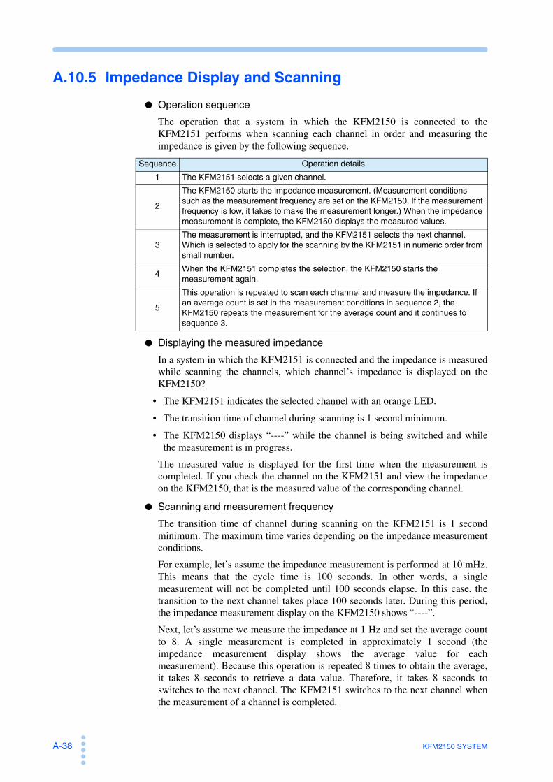
A-38 KFM2150 SYSTEM
A.10.5 Impedance Display and Scanning
Operation sequence
The operation that a system in which the KFM2150 is connected to theKFM2151 performs when scanning each channel in order and measuring theimpedance is given by the following sequence.
Displaying the measured impedance
In a system in which the KFM2151 is connected and the impedance is measuredwhile scanning the channels, which channel’s impedance is displayed on theKFM2150?
• The KFM2151 indicates the selected channel with an orange LED.
• The transition time of channel during scanning is 1 second minimum.
• The KFM2150 displays “----” while the channel is being switched and whilethe measurement is in progress.
The measured value is displayed for the first time when the measurement iscompleted. If you check the channel on the KFM2151 and view the impedanceon the KFM2150, that is the measured value of the corresponding channel.
Scanning and measurement frequency
The transition time of channel during scanning on the KFM2151 is 1 secondminimum. The maximum time varies depending on the impedance measurementconditions.
For example, let’s assume the impedance measurement is performed at 10 mHz.This means that the cycle time is 100 seconds. In other words, a singlemeasurement will not be completed until 100 seconds elapse. In this case, thetransition to the next channel takes place 100 seconds later. During this period,the impedance measurement display on the KFM2150 shows “----”.
Next, let’s assume we measure the impedance at 1 Hz and set the average countto 8. A single measurement is completed in approximately 1 second (theimpedance measurement display shows the average value for eachmeasurement). Because this operation is repeated 8 times to obtain the average,it takes 8 seconds to retrieve a data value. Therefore, it takes 8 seconds toswitches to the next channel. The KFM2151 switches to the next channel whenthe measurement of a channel is completed.
Sequence Operation details
1 The KFM2151 selects a given channel.
2
The KFM2150 starts the impedance measurement. (Measurement conditions such as the measurement frequency are set on the KFM2150. If the measurement frequency is low, it takes to make the measurement longer.) When the impedance measurement is complete, the KFM2150 displays the measured values.
3The measurement is interrupted, and the KFM2151 selects the next channel. Which is selected to apply for the scanning by the KFM2151 in numeric order from small number.
4When the KFM2151 completes the selection, the KFM2150 starts the measurement again.
5
This operation is repeated to scan each channel and measure the impedance. If an average count is set in the measurement conditions in sequence 2, the KFM2150 repeats the measurement for the average count and it continues to sequence 3.

KFM2150 SYSTEM I-1
A
AC 5-5, 5-12AC INPUT -17alarm occurrence and release 4-12alarm volume 4-17Application software 1-12, 4-24AVE 5-18
B
backup battery, replacement of 6-2bench top type 1-8bottom voltage, ensuring of A-25
C
calibration 6-3cause of alarms and remedies 4-12CC (constant current) mode A-16CC+CV mode A-16, A-22CD-ROM, contents of 4-24contact resistance A-11contrast 4-16CONTROL TERMINAL A-3CONTROL TERMINAL arrangement A-3current capacity and conductive cross-sectional
area A-10CV (constant voltage) mode A-16CV mode A-22
D
DC 5-5, 5-12, 5-17DC INPUT -17DEPTH 5-16display contrast 4-16
E
earth 2-22, 3-16earth leakage circuit breaker 3-18EXT CONT -17
F
factory default settings 4-17FCTester 4-24firmware version 1-2, 4-4, 4-6FREQ 5-11fuel cell voltage, required A-25
G
GPIB address, setting of 4-18grounding (earth) 2-22, 3-16
I
if troubleshooting fails 4-5impedance measurement system 1-6inductance A-12, A-23INIT 4-17items to be displayed and their positions, selection
of 5-19
J
J1 connector pin arrangement A-5J1/J2 -17judgement function 5-24judgement function, disabling of 5-26judgement function, enabling of 5-25
K
keys, problems with 6-4
L
load current, four states of 5-6load off operation when a protection function is
activated 5-9local mode, switching to 4-17lock 4-16
M
master unit 2-8Maximum power consumption 2-23maximum power consumption 3-18measured values, unstable 6-4measurement accuracy 7-8measurement accuracy, determination of 7-7measurement method, selection of 5-11measuring AC current as a percentage of the load
current 5-13measuring AC current, setting of 5-12measuring frequency, setting of 5-11memory, recalling of 4-15memory, saving to 4-14MENU 4-26menu display 4-7METHOD 5-11, 5-15
N
noisy environment A-8
O
operating humidity range 7-14, 7-16operating temperature range 7-14, 7-16
Index

I-2 KFM2150 SYSTEM
operation not according to the settings 6-4options 1-11overheat protection (PLZ4W OHP) 4-8overpower protection (OPP) 4-8overvoltage protection (PLZ4W OVP) 4-8
P
panel operation, locking of 4-16parts that you prepare 1-5PD 5-16PLZ FORMATION 4-5PLZ NO RESPONSE 4-4PLZ4W remote sensing 2-10, 3-8polarity A-8, A-9power 4-2, 4-6power cord, inspection of 6-2POWER switch off 4-3, 4-6POWER switch on 4-2, 4-6power-up, problems with 6-3PROTECT 4-12protection function, structure of 4-8protection functions, type of 4-8PT 5-16pulse depth, setting of 5-15pulse transition time, setting of 5-16pulse width, setting of 5-15PW 5-15
R
rack mount bracket 1-11rack mount type 1-9RECALL 4-15recommended power cable 3-18remedies when an error message is displayed 4-4remote sensing terminal -17reverse connection protection (PLZ4W REV) 4-8RS232C -17RS232C configuration 4-20
S
sampling region 5-17sampling start position (Position) 5-17sampling, setting of 5-16scanning speed A-37serial number 1-2short-circuit correction function 5-21slave unit 2-8soft start, details of 5-7start and end times of the fuel cell (soft start),
synchronizing to 5-2storage humidity range 7-14storage temperature range 7-14, 7-16STORE 4-14system serial number -17, -20, -24, 1-2, 2-2, 3-2,
4-4, 4-5system, turning on 4-2
T
temperature A-9TRNSN 5-16
U
undervoltage protection (PLZ4W UVP) 4-8USB cable 2-20, 3-14USB configuration 4-22
V
version check display 4-4, 4-6voltage sensing undervoltage protection (SENSE
UVP) 4-9
W
WIDTH 5-15wire inductance 2-9, 3-8wire, voltage drop in A-20wires in contact with each other 3-7


KIKUSUI ELECTRONICS CORP.
http://www.kikusui.co.jp/en
1-1-3 Higashiyamata, Tsuzuki-ku, Yokohama, 224-0023, JapanTel: +81-45-593-7570 Fax: +81-45-593-7571
Website