ethanol from corn: clean renewable fuel for the future, or drain on

Fuel Cell Procedure
Document No.:
3350-00003 Title/Description:
Fuel Cell Drain Procedure Author:
Kurt Stiffel Approved by:
Revision:
1-00 Effective Date:
1.0 Reference Documents
All released OOI documents in Alfresco 3161-20000 Fuel Cell Integration and Verification Plan 3350-00003 Fuel Cell Drain Procedure 3350-00004 Spill Response Procedure Fuel cell reference documents are located on VAULT at: Vault\Project_Files\Documentation\Power\Power Notebook\Fuel Cell\
2.0 Definitions & Acronyms
See Section 3.0 of document 3161-20000
3.0 Training Requirements
All personnel that will handle the methanol (including contractors) at WHOI facilities are required to complete WHOI’s hazard communication and chemical safety online training and follow WHOI’s hazardous communication and chemical safety procedure. Contact the WHOI EH&S office for links to required training courses and documentation. Information can also be found at http://ehs.whoi.edu/ehs/.
4.0 Required PPE and Safety Notes
All personnel within a 25 foot radius of the buoy are required to don splash protection goggles and chemical resistant gloves. These can include polyvinyl plastic, neoprene or rubber. Contact information for WHOI EH&S is 508-289-3347. Ensure operations are performed in compliance with applicable WHOI/SIO/OSU safety protocols, OOI Safety Plan (1006-10002) and CGSN EH&S Plan (3101-00009). Read and follow all safety warnings in the MSDS. Once the Safety Review in Section 8.1 is complete, have each operator sign-off in the signature block.
5.0 Required Tools & Equipment
Buoy Fueling Assembly consisting of: 10’ Fill Tube with valve and Quick Disconnect, 3/4” OD (1) 15’ Fill Tube with valve and Quick Disconnect, 3/4” OD (1) 25’ Vent Tube and Quick Disconnect, 3/4” OD (1) 25’ Pressure Gauge and Pressure Sensor Tube, ¼” OD (1) 55 Gallon Drum Pump on stand with Quick Disconnects (1) 55 Gallon Drum Wrench (1) 30’ Drum-Buoy Bonding Cable (1) 10’ Drum-Ground Grounding Cable (1) 55 Gallon Drum Premixed Methanol Fuel (6) 55 Gallon Drum Grounding Rod (1) 9/16” Wrench (1) ½” Wrench (1) 1-1/8” Wrench (1) 1-1/16” Wrench (1) Pipe Wrench (1) Isopropyl Alcohol (A/R) Large Plastic Bags (A/R)
Fuel Cell Drain Procedure 3350-00003
Page 2 of 12
Chemical Resistant Gloves (A/R) Splash Protection Goggles (A/R) PIG Spill Kit (1) Kim Wipes (A/R) Teflon Tape (A/R) Fire Extinguisher, ABC (1) Traffic Cones or Caution Tape (A/R) Zip Ties, Large (A/R) Extension Cord (A/R) Handheld hydrogen gas sensors: RKI Eagle 2 Q size cylinder of nitrogen gas with pressure regulator ½" ID Flexible tubing (length dependent on deck configuration, see Section 6.1))
6.0 Draining Precautions
Unused fuel and empty fuel drums shall be stored outside of the main building in an approved storage enclosure. Coordinate with the local EH&S department if a specific location has not yet been determined.
Only one fuel container shall be handled at a time during operations. Keep all additional containers in the approved storage enclosure.
Only one container shall be open at a time during fuel transfer.
The area around the buoy shall be marked off with cones or safety tape and monitored during operations.
Only personnel directly involved with draining should be within 25 feet of the mooring during operations.
A solvent spill kit capable of absorbing the entire contents of each shipping container (drum) shall be immediately adjacent to the mooring during filling.
No smoking or any sources of ignition within 50 feet of the mooring.
Personnel involved in draining shall wear protective gloves and protective eyewear.
All equipment involved in draining shall be grounded.
Stage a portable fire extinguisher (ABC) within 25-50 feet of draining operations.
All down gradient storm drains (if present and located within 50 feet) shall be completely blocked or covered.
Safety Review to be reviewed and followed by all participants.
7.0 Procedure Step Instructions
8.1 SAFETY REVIEW
8.1.1 Read through this Safety Review prior to commencing draining operations. Once completed, sign and date where indicated on Attachment #3.
8.1.2 Identify the nearest chemical wash-down station relative to the draining operations. Ensure the path to the shower is clear and is no more than a 10 second walking distance away.
8.1.3 Ensure the solvent spill kit is located immediately adjacent to the mooring prior to filling.
8.1.4 Ensure protective gloves and eyewear is available for each person involved in operations. Only personnel directly involved in the operations should be present. Additional PPE should be available if additional personnel are necessary.
8.1.5 Find all storm drains that are within 50 feet of draining operations and located downhill. These shall be blocked or covered for the duration of the operations to prevent any spilled fuel from entering the drain system. Contact EH&S if assistance is necessary.

Fuel Cell Drain Procedure 3350-00003
Page 3 of 12
7.0 Procedure Step Instructions
8.1.6 Ensure fire extinguisher is located within 25-50 feet of draining operations and that the extinguisher is rated for ABC.
8.1.7 The area within 25 feet of the buoy shall be marked off with cones or safety tape during operations. Only personnel directly involved with draining and wearing appropriate PPE should be within this area.
8.1.8 During operations, one person shall be in charge of the fuel pump, while the second person shall monitor the area for ignition sources. No one should be allowed within 50 feet of the draining operation with an active ignition source (e.g. lit cigarette, welding torch).
8.1.9 Grounding of the fill equipment is important to ensure a spark is not generated during fluid transfer. Ensure an adequate ground location is available for use. If necessary, a grounding rod can be installed and utilized for this activity.
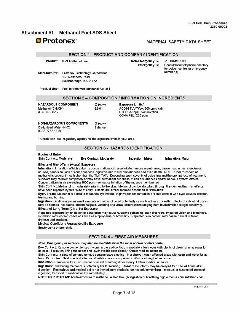
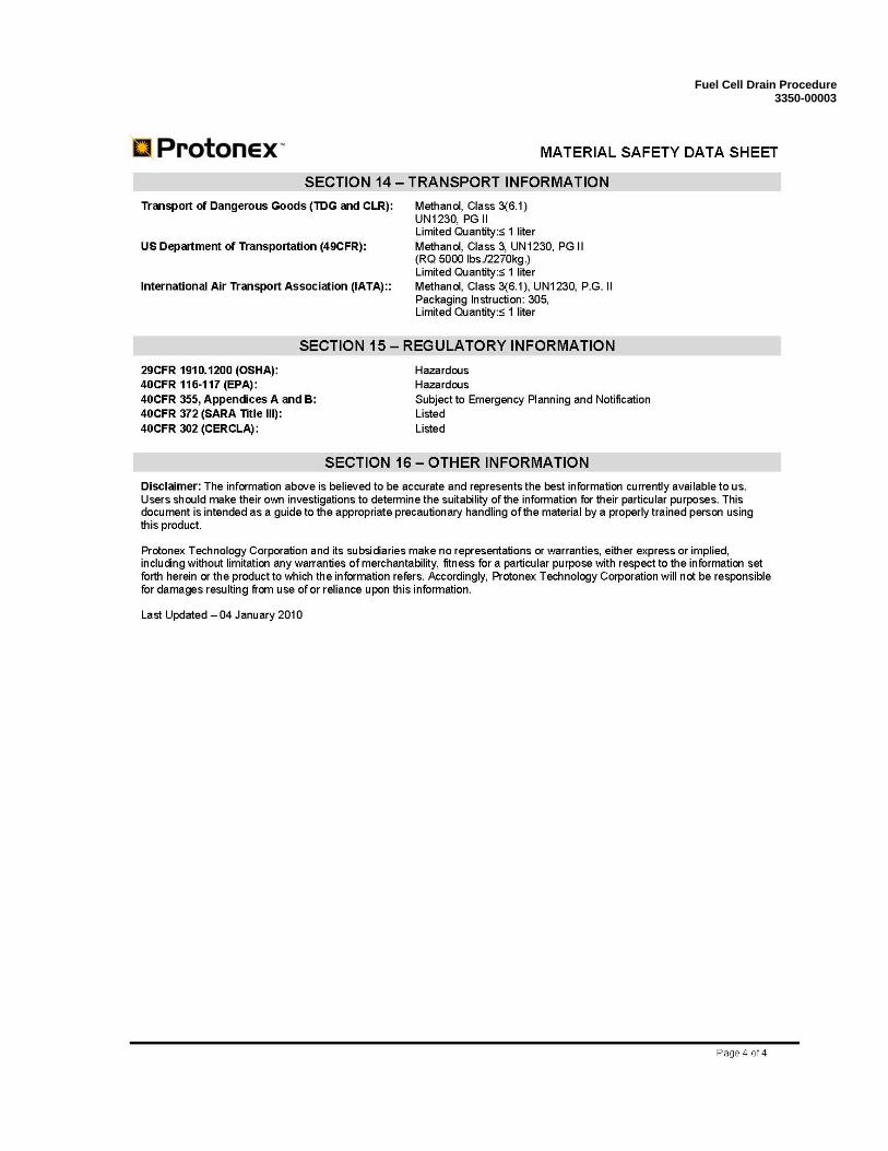
8.1.10 The SDS sheet for the Methanol Fuel is located at the end of this document in Attachment #1. Review the SDS sheet prior to handling of the fuel.
8.1.11
In the event of a spill of fuel, the following steps will be taken (see 3350-00004): Small Spills (containable) - Soak up spill with the non-combustible absorbent material found in the Spill Kit. Place the used absorbent material back into the Spill Kit container for disposal. Flush area with water. Large Spills (uncontainable) – Use the Spill Kits to absorb as much of the fuel as possible and contact local EH&S (for WHOI contact at 508-289-3347) for assistance.
8.1.12 Operations should not be performed during inclement weather. Events such as thunderstorms, heavy rain or snow and extreme cold temperatures can affect the judgment of the operators and impede the response time of emergency personnel.
8.1.13 Move all empty fuel drums into the approved storage area when not in use. Having multiple drums in the operations area is not desirable.
8.1.14 Draining operations shall always be conducted by two persons trained in methanol handling procedures. This is to ensure that if one operator is incapacitated, the second operator will be able to contact emergency personnel.
8.1.15
All personnel that will handle the methanol fuel (including contractors) at WHOI facilities are required to complete WHOI’s hazard communication and chemical safety online training and follow WHOI’s hazardous communication and chemical safety procedure. If training is necessary, contact the WHOI EH&S office for links to required training courses and documentation.
8.2 Draining Setup
8.2.1
Ensure that the Buoy to be drained is located in such a place as to satisfy the following: - A minimum of 50 feet from the nearest building/facility. - A maximum of a 10 second walking distance away from the nearest chemical wash-down station. - Unit is within 10 feet of the nearest ground
If all of these conditions are not met, reposition the Buoy as required.
8.2.2 Mark off area surrounding the fuel storage system using cones or clearly visible tape. Ensure a radius of 25 feet around the buoy is clearly marked.
8.2.3 Ensure there are no active ignition sources located within 50 feet of the buoy location.
8.2.4 Notify any nearby personnel of the operations about to take place. This will ensure they do not enter the marked off area during the process.
8.2.5 Stage Spill Kit and portable fire extinguisher next to Buoy.
Fuel Cell Drain Procedure 3350-00003
Page 4 of 12
7.0 Procedure Step Instructions
8.2.6 Block off any storm drains located downhill of the draining location and within 50 feet.
8.2.7 Remove the Buoy Fueling Assembly from the transportation case. Locate all necessary items from the required tools and equipment list.
8.2.8 If a power outlet is not located near the Buoy, run an extension cord to the fuel pump location.
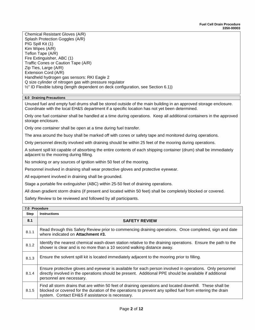
8.2.9
Move an empty drum within 20 feet of the Buoy and 10 feet of the ground location. Ideally, the drum should be located in front of the Buoy Fuel Flange (see picture). Ensure there is sufficient space to bring in the next drum once the first is empty.
8.2.10 Don Personal Protective Equipment (PPE) including chemical resistant gloves and splash protection goggles.
8.2.11 Remove both plastic bung caps from the methanol drum using drum wrench. Place both bungs in a plastic bag to ensure they stay clean and set aside.
8.2.12
On the Flange Assembly, remove the metal caps from the Vent, Fill and Pressure Port valve. Place caps in a plastic bag to ensure they stay clean and set aside. [Note: Refer to Attachment #2 for a detailed schematic of the hose and port configuration for draining the fuel bladder.]
8.2.13 Insert the fuel drum grounding rod into one of the fuel drum’s open ports. Attach one end of the grounding cable (10 feet long) to the fuel drum grounding rod and the other to the nearest ground location.
8.2.14 Ground the Buoy flange assembly by attaching the 30 foot long bonding cable from the Flange to the drum grounding rod.
8.2.15 Remove the (4) valve handles from their storage bag located in the transit case of the Buoy Fueling Assembly. Reattach the valve handles to the appropriate valves on the Buoy Fuel Flange.
Fuel Cell Drain Procedure 3350-00003
Page 5 of 12
7.0 Procedure Step Instructions
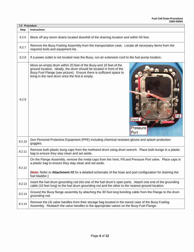
8.2.16
Attach the 10 foot long Fill Tube to the Discharge side of the Drum Pump via the quick disconnect fitting. Insert the solid tube end of the tube into the open buttress port of the fuel drum and ensure that it is inserted such that the end of the tube is resting on the bottom of the drum. [Note: All valves should be closed at this time.] [Note: Refer to picture on right for connections to the Fuel Pump Assembly.]
8.2.17 Attach the 15 foot Fill Tube to the Intake side of the drum pump via the quick disconnect fitting. Attach the swaged end of the tube to the Fill Valve on the Buoy Fuel Flange using the 1-1/8” wrench.
8.2.18 Attach the 25 foot Vent Tube to the Vent Valve on the Buoy Fuel Flange using the 1-1/8” wrench. Secure the other end of the tube to the side of the buoy, above the height of the drum. Ensure hose is secure utilizing zip ties.
8.2.19 Ensure the Main Pump Switch is in the off position and plug the electrical cord into the nearest electrical outlet.
8.3 Draining Operations
8.3.1 Open all valves in the assembly. There are a total of (5) valves, with (3) located on the Buoy Fuel Flange and (2) on the Fuel Pump Assembly.
8.3.2 Move the Main Pump Switch to the On position.
8.3.3
The pump is operated by holding down the spring loaded momentary switch on the end of the gray cable attached to the Fuel Pump Assembly. The unit will not run unless the switch is held down. Once activated, the pump will take approximately 6 minutes to fill an empty drum. [Note: 5-6 drums of fuel are necessary to completely drain a full bladder. Total volume of a full fuel bladder is 285 gallons.]
8.3.4 Once the drum is full, release the momentary switch on the Fuel Pump Assembly and close all valves. [Note: Do not overfill the drums. Fill to indicator line on side of drum.]
8.3.5 Move an empty drum into place next to the full drum. Remove both plastic bung caps from the empty methanol drum using drum wrench.
8.3.6
Move the Fill Tube, Vent Tube and Grounding Rod to the empty drum. Ensure all components are secure using zip ties. Once moved, use the bungs just removed to seal up the full drum. Prior to proceeding with the draining, remove the full drum from the area and return it to the approved storage location. [Note: The full drum should be marked that it is full of removed fuel. The fuel is now considered contaminated and will not be used in future deployments.]

Fuel Cell Drain Procedure 3350-00003
Page 6 of 12
7.0 Procedure Step Instructions
8.3.7 Repeat the above steps starting with 8.3.1 until the bladder is empty. Close all valves.
8.4 Bladder Purge
8.4.1 Unplug the Fuel Pump electrical power cord plug from the outlet and coil up the cord.
8.4.2 Detach the Pressure Gauge and Pressure Sensor Tube assembly from the Pressure Port Valve using the 9/16” wrench. Coil and bag the tube assembly for future use.
8.4.3 Detach the 25 foot Vent Tube from the Vent Valve on the Buoy Fuel Flange using the 1-1/8” wrench. Once removed, hold this end of the vent line higher than the top of the drum. This will allow any residual methanol within the tube to flow back into the drum. Coil and bag the Vent Tube and store for future use.
8.4.4 Detach the 10 foot Fill Tube from the Discharge side of the drum pump via the quick disconnect fitting. Empty any residual methanol from the Fill Tube into the just emptied fuel drum. Coil and bag the 10 foot Fill Tube and store for future use.
8.4.5
Detach the 15 foot Fill Tube from the Intake side of the drum pump via the quick disconnect fitting. Detach the swaged end of the tube to the Fill Valve on the Buoy Fuel Flange using the 1-1/8” wrench. Once removed empty any residual methanol within the tube back into the drum. Coil and bag the Fill Tube and store for future use.
8.4.6 Set regulator on the Nitrogen cylinder to 1 psi.
8.4.7 Attach the ½” flexible tubing from the Nitrogen cylinder to the Pressure Port valve on the Buoy Fuel Flange.
8.4.8 Open both the Pressure Port Valve and the Vent Valve on the Buoy Fuel Flange. Turn on the Nitrogen gas.
8.4.9 Use the Gas Analyzer to monitor the Vent Valve. Flush the well with nitrogen until the Oxygen sensor records less than 10% LEL.
8.4.10 Turn off the Nitrogen and close all valves.
8.5 Break-down
8.5.1 Detach flexible tubing from Pressure Port and store in transit case.
8.5. Remove the grounding rod from the drum opening. Wipe dry and bag for future use.
8.5. Remove all grounding cables and coil for future use.
8.5. Replace the (2) bungs back onto the open drum. Tighten with the bung wrench.
8.5. Replace the (3) metal caps onto the Buoy Fuel Flange valves.
8.5. Move the final fuel drum back to the designated fuel storage area.
8.5 Draining Artifacts
8.5.1 Post the signed draining procedure (Attachment #3) to Vault and notify management that the buoy is drained.
Fuel Cell Drain Procedure 3350-00003
Page 7 of 12
Attachment #1 – Methanol Fuel SDS Sheet

Fuel Cell Drain Procedure 3350-00003
Page 8 of 12

Fuel Cell Drain Procedure 3350-00003
Page 9 of 12
Fuel Cell Drain Procedure 3350-00003
Page 10 of 12

Fuel Cell Drain Procedure 3350-00003
Page 11 of 12
Attachment #2 – Schematic of equipment configuration for draining
Fuel Cell Drain Procedure 3350-00003
Page 12 of 12
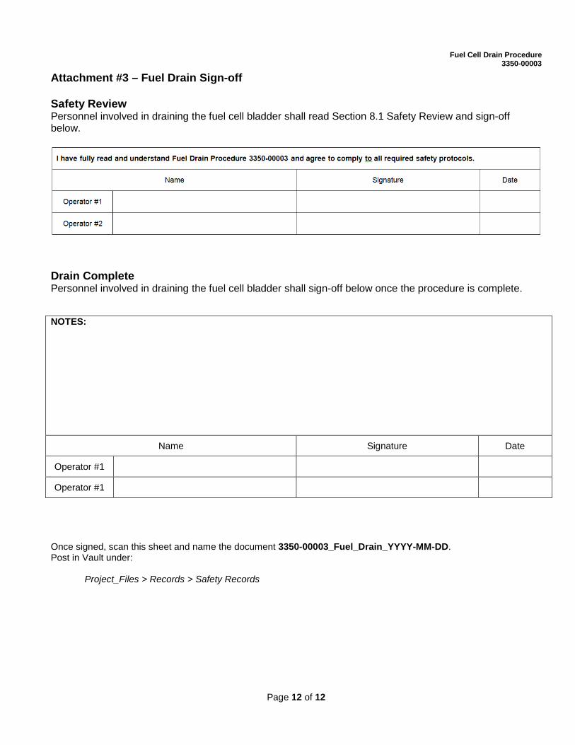
Attachment #3 – Fuel Drain Sign-off Safety Review Personnel involved in draining the fuel cell bladder shall read Section 8.1 Safety Review and sign-off below.
Drain Complete Personnel involved in draining the fuel cell bladder shall sign-off below once the procedure is complete. NOTES:
Name Signature Date
Operator #1
Operator #1
Once signed, scan this sheet and name the document 3350-00003_Fuel_Drain_YYYY-MM-DD. Post in Vault under: Project_Files > Records > Safety Records