Fuel and System Interaction Effects on Urea-SCR Control of NOx … · 2018-12-28 · Fuel and...
32
Fuel and System Interaction Effects on Urea-SCR Control of NO x in Diesel Exhaust Aftertreatment Presented by: Ragini Acharya Co-authors: Mahabubul Alam and André L. Boehman The Energy Institute The Pennsylvania State University University Park, PA 16802 Ninth DOE Crosscut Workshop on Lean Emissions Reduction Simulation (CLEERS) May 2-4, 2006, University of Michigan-Dearborn, MI
Transcript of Fuel and System Interaction Effects on Urea-SCR Control of NOx … · 2018-12-28 · Fuel and...

Fuel and System Interaction Effects on Urea-SCR Control of NOx in Diesel Exhaust Aftertreatment
Presented by:Ragini Acharya
Co-authors: Mahabubul Alam and André L. Boehman
The Energy InstituteThe Pennsylvania State University
University Park, PA 16802
Ninth DOE Crosscut Workshop on Lean Emissions Reduction Simulation (CLEERS)
May 2-4, 2006, University of Michigan-Dearborn, MI

2
AcknowledgmentsThe authors wish to thank Etop Esen, Doug Smith, Kirk Miller, Keith Lawson, Ed Casey, Rafael Espinoza and Jim Rockwell of ConocoPhillips, Joseph Patchett of Engelhard Corporation and John Wright and Edward Lyford-Pike of Cummins Engine Company for their support of this work. This work is a part of an Ultra Clean Fuels project entitled “Ultra Clean Fuels from Natural Gas,” sponsored by U.S. Department of Energy under Cooperative Agreement No. DE-FC26-01NT41098. The Government reserves for itself and others acting on its behalf a royalty-free, nonexclusive, irrevocable, worldwide license for Governmental purposes to publish, distribute, translate, duplicate, exhibit, and perform this copyrighted paper.
3
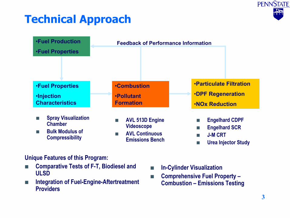
Technical Approach
•Fuel Properties
•Injection Characteristics
•Combustion
•Pollutant Formation
•Particulate Filtration
•DPF Regeneration
•NOx Reduction
•Fuel Production
•Fuel PropertiesFeedback of Performance Information
Spray Visualization ChamberBulk Modulus of Compressibility
AVL 513D Engine VideoscopeAVL Continuous Emissions Bench
Engelhard CDPFEngelhard SCRJ-M CRTUrea Injector Study
Unique Features of this Program:Comparative Tests of F-T, Biodiesel and ULSDIntegration of Fuel-Engine-Aftertreatment Providers
In-Cylinder VisualizationComprehensive Fuel Property –Combustion – Emissions Testing

4
Schematic Diagram of Cummins ISB Test Stand

5
AVL 8-Mode Test Cycle
Mode RPM Torque (ft-lb) Weighting Factor
1 800 No load 0.35
2 1025 77 0.0634
3 1199 252 0.0291
4 1408 378 0.0334
5 2700 80 0.084
6 2605 178 0.1045
7 2605 307 0.1021
8 2491 426 0.0734

6
Baseline Emissions Studies – Impacts of Sulfur Content and Biodiesel Blending
0
1
2
3
4
5
6
7
8
9
10
1 2 3 4 5 6 7 8Mode
PM E
mis
sion
s (g
/kg
fuel
)
BP325BP15B20-BP325B20-BP15
0.0
0.5
1.0
1.5
2.0
2.5
3.0
3.5
4.0
CO NOx PM HC Emissions
Uni
t, g/
kWh
BP325BP15B20-BP325B20-BP15
(11 %)
(4.4 %)
(20 %)
(16 %)
MY 2007 NOx emissions 0.268 gm/kwh
MY 2007 PM emissions 0.0134 gm/kwh
Parenthesis indicates reduction of emissions with BP15 compared to BP325

7
Catalyzed DPF Regeneration Test
Inlet NO Emission prior to DPF
300
400
500
600
700
800
900
200 250 300 350 400 450 500Temperature (degrees C)
DPF
Inle
t NO
x (p
pm)
LSD
LSD/B20
ULSD
ULSD/B20

8
0
10
20
30
40
50
60
200 250 300 350 400 450 500Temperature (degrees C)
Perc
ent N
O c
onve
rsio
n
LSD
LSD/B20
ULSD
ULSD/B20
Catalyzed DPF Regeneration Test
NO to NO2 conversion across the DPF

9
SCR NOx Control Study – Experimental Approach
Develop Urea Dosing/Injection Systemy Use a simulant fluid and cold flow simulation to verify uniformity of
urea injection process with twin-fluid injectory Butane as simulant fluid, detection with sampling probe and FID HC
analyzer
Experiments with Coupled DPF and Urea-SCR Systemsy SCR downstream of DPFy Experiments were performed using four different fuels, including
325-ppm sulfur diesel fuel (BP325), an ultra low sulfur diesel fuel with 15-ppm sulfur (BP15) and blends of each with 20% (w/w) biodiesel (B20-BP325 and B20-BP15 respectively)
y Ramp test cycle was designed for catalyst characterization as a function of exhaust temperature, with fixed engine speed at 1400rpm and gradually increasing engine load
y FTIR spectroscopy and on-line emissions analysis

10
Cold Flow Simulation of Urea InjectorObjectives:
Determine whether the commercial urea injection nozzle can provide uniform composition as flow enters the SCR reactors.Use “cold flow” and a “simulant” fluid to represent hot test conditions.
Approach:Use n-butane as the simulant and an FID analyzer to determine uniformity of n-butane concentration across the pipe.

11
Cold Flow Simulation of Urea Injector
Observation:y Excellent uniformity in both x- and y-planes
Simulant concentration distribution in x-plane Simulant concentration distribution in y-plane

12
Urea Evaporation and Decomposition
Step 1: EvaporationCO2(NH2)2 (aqueous) --> CO2(NH2)2 (solid)+x H2O
Step 2: DecompositionyMechanism 1
CO2(NH2)2--> 2 •NH2+CO•NH2+NO-->N2+H2OyMechanism 2
CO2(NH2)2--> NH3+HNCOHNCO+H2O--> NH3+CO2

13
Experimental Setup for Urea-SCR Testing

14
Engine Operating Points for Ramp Test Cycle
Mode Engine RPM Load (lb-ft) % Load Time(min)1 1400 146 31.9 702 1400 180 39.4 703 1400 215 46.9 704 1400 247 54.1 705 1400 281 61.5 706 1400 315 68.9 707 1400 349 76.3 708 1400 382 83.7 70

15
Urea Injection Rates
The different urea injection rates are symbolized by NH3/NOX ratio.Molar ratio1.0 NH3/NOX , 0.75 NH3/NOX , and 0.65 NH3/NOXwere tested.

16
NOX Emissions and NOX Conversion
0.8
0.85
0.9
0.95
1
1.05
1.1
250 300 350 400 450 500 550
BP 15BP 325B20-BP325B20-BP15
% N
Ox C
onve
rsio
n/10
0
Catalyst Temperature (deg C)
Observation: Engine-out NOx emissions less (5%) for BP15, biodiesel blends show increase in NOx
emissionsThe SCR catalyst gives similar performance for four fuels between experimental
uncertainty.

17
NOX Reduction Mechanism
Super-stoichiometeric reactionsy6NO+8NH3-->7N2+12H2Oy2NO2+4NH3+O2-->3N2+6H2O
Stoichiometeric reactionsy4NO+4NH3+O2-->4N2+6H2Oy2NO+ 2NO2+ 4NH3-->4N2+6H2O
Nitrous oxide formationy4NO+4NH3+3O2-->4N2O+6H2O
Focus of present study: Characterizing and confirming the overall reactions for SCR system while DPF is placed upstream.

18
Variation Between Tests: Dependence on DPF Outlet
For higher NO2 Inlet/NOx Inlet, lower NH3 Consumed/NOx Consumed is observed and vice-versa. It can also be seen that NH3 Consumed/NOx Consumed is significantly less than 1.0
0
0.2
0.4
0.6
0.8
1
250 300 350 400 450 500 550
Test 1Test 2
Catalyst Temperature (deg C)
NH
3 Con
sum
ed/N
Ox C
onsu
med
0
0.1
0.2
0.3
0.4
0.5
250 300 350 400 450 500 550
Test 1Test 2
Catalyst Temperature (deg C)
NO
2 Inl
et /
NO
x Inl
et
BP 15 BP 15

19
Variation Between Tests: Dependence on DPF Outlet
Similar to the BP15 fuel, the NH3 Consumed/NOx Consumed shows different behavior for different NO2 Inlet/NOx Inlet variation in both cases.Difference in NO2 inlet in the exhaust feed to the SCR reactors arose from differences in the particulate matter loading in the DPF
0
0.2
0.4
0.6
0.8
1
250 300 350 400 450 500 550
Test 1Test 2
Catalyst Temperature (deg C)
NH
3 Con
sum
ed/N
Ox C
onsu
med
0
0.1
0.2
0.3
0.4
0.5
250 300 350 400 450 500 550
Test 1Test 2
Catalyst Temperature (deg C)
NO
2 Inl
et /
NO
x Inl
et
B20-BP325 B20-BP325

20
Ammonia Consumption as a Function of NO2 Inlet
As NO2 Inlet/NOx Inlet starts decreasing, the NH3 Consumed/NOx Inlet tends to increase towards 1.0.
While NO2 Inlet/NOx Inlet is considerably higher (0.30-0.35) and NH3Consumed/NOx consumed is significantly lower than 1.0.
BP325 B20-BP15

21
Variation of NH3 Slip/NOx Inlet with Catalyst Temperature
Stoichiometric urea injection (i.e., the NH3 Inlet/NOx Inlet ratio is equal to 1.0).High ammonia slip at lower temperature.Ammonia slip is different for various fuels.Ammonia slip is different in two test runs even while using the same fuel.All ammonia is not consumed while peak NOx conversion is achieved if NO2 Inlet/NOx Inlet is non-zero.NH3 Slip/NOx Inlet approaches zero at as NO2/NOx decreases.In the absence of NO2, the urea-SCR process NH3/NOx ratio is equal to 1.0 but in the presence of NO2, the NH3slip also depends on the NO2concentration
0
0.2
0.4
0.6
0.8
1
250 300 350 400 450 500 550
BP15
BP325
B20-BP15
B20-BP325 (Test 1)
B20-BP325 (Test 2)
NH
3n S
lip /
NO
x Inl
et
Catalyst Temperature (deg C)

22
Role of Carbon monoxide
No decrease in CO emissions across the urea-SCR reactors.Carbon monoxide is not one of the reducing agents in the SCR.
0
0.0001
0.0002
0.0003
0.0004
0.0005
39 47 57 66 74 83 92 102
Before SCR BP15After SCR BP15Before SCR BP325After SCR BP325Before SCR B20-BP15After SCR B20-BP15Before SCR B20-BP325After SCR B20-BP325
CO
(g/b
hp-h
r)
Engine Power (bhp)

23
Role of Hydrocarbons
There is no decrease in THC emissions across the urea-SCR reactors. This observation rules out the possibility of NOxreduction by THC.
0
0.0002
0.0004
0.0006
0.0008
0.001
40 57 101
Before SCR-BP15After SCR-BP15Before SCR-BP325After SCR-BP325
THC
(g/b
hp-h
r)
Engine Power (bhp)

24
Comparison of % NO2 Conversion and % NO Conversion
0
20
40
60
80
100
283 296 328 361 395 430 465 494
% C
onve
rsio
n
Catalyst Temperature (deg C)
0
20
40
60
80
100
283 296 328 361 395 430 465 494
% C
onve
rsio
n
Catalyst Temperature (deg C)
0.65 NH3/NOx0.75 NH3/NOx

25
FTIR Spectra of SCR-out Exhaust
The spectra show no traces of (less than 0.001%) N2O in the emissions out of the SCR system. The standard spectrum in both cases corresponds to nitrous oxide concentration equal to 0.001%.
0.00 0.01
0.02
0.03
0.04
0.05
0.06
0.07
0.08
0.09
0.10
0.11
0.12
2120 2140 2160 2180 2200
Standard Spectrum
Wave number (cm-1)
Measured Spectrum
Abs
orba
nce
BP 15 and 0.75 NH3/NOx

26
FTIR Spectra of SCR-out Exhaust
Similar to case with BP15No traces of N2O.
0.00 0.01
0.02
0.03
0.04
0.05
0.06
0.07
0.08
0.09
0.10
0.11
0.12
2120 2140 2160 2180 2200
Standard Spectrum
Wave number (cm-1)
Measured Spectrum
Abs
orba
nce
BP 325 and 0.75 NH3/NOx

27
Conclusions
The results reported here show that there is significant potential for both beneficial and adverse interaction between a diesel particulate filter and a urea-SCR reactor in a diesel exhaust after-treatment system. In the present work, due to the presence of an oxidizing DPF reactor upstream of the urea-SCR reactor, the composition of NOx going into the urea-SCR reactor changed depending upon the conditions within the DPF. The engine out NOx emissions have NO as the major constituent and NO2 is negligible. The DPF reactor oxidized a portion of NO into NO2, making it a major constituent in the NOx inlet to urea-SCR reactor.

28
Conclusions (contd.)With this possibility for variation in the NO/NO2 ratio, the urea-SCR system was characterized for the effect of NO2 on NH3consumption for NOx reduction process, relative selectivity of NO2 with respect to NO, and nitrous oxide formation. These measurements were accomplished by examining four test fuels, i.e., BP15, BP325 and their 20% w/w blends with biodiesel, in the exhaust, since the effects of these fuel variations led to variations in NO/NO2 ratio. The SCR catalyst is more selective for NO2 than NO in the NOxreduction reaction. Catalytic activity for NO2 is higher than NO at lower temperatures (below 300°C). The SCR-out emissions do not contain N2O. So, while N2O may be formed as an intermediate transient product, it is not a final product for the catalyst formulation in this work.

29
Discussions
Possibility of NO adsorption on the catalyst surface at lower temperatures.Connection between NO2 concentration in DPF-out (or SCR-in) exhaust and NH3 consumption in SCR reactors can not be denied.Low ammonia consumption due to diffusionallimitations at low temperaturesyNOx conversion efficiency is close to 95%
Ammonia adsorption in SCRy The SCR catalyst were used without urea injection and no
change in NOx measurements before and after SCR reactors was observed.

30
Discussions (contd.)
Possibility of sub-stoichiometeric overall reactionyGibb’s free energy calculations show larger negative ∆G°
with respect to the stoichiometeric reactions.6NO+NO2+16/3NH3-->47/3N2+8H2O∆G° = -54.64*8-20.72*6-12.39*1+3.97*(16/3) = -552.66 Kcal/mol
yMore negative ∆G° means more spontaneous reaction.y Chemical thermodynamic calculations alone are not
adequate for postulated reaction to take place.yOverall reaction kinetics can not be confirmed as a factor
in the sub-stoichiometeric consumption of ammonia.

31
RecommendationsThe results indicate that under some conditions a substoichiometric overall reaction occurs between NH3 and NOx.Although thermodynamically possible, the substoichiometric overall reaction cannot be confirmed due to lack of activation energy measurements.The effect of NO2 on NH3 consumption in SCR catalysis process shows the significance of measuring or estimating NO2 in the feed to the SCR units to achieve optimum performance and efficiency of the SCR system and to minimize SCR slip.If the engine operating conditions are such that the DPF is very active and NO2/NOx ratio is significant in the feed to the SCR, then less NH3 than stoichiometric is required to completely reduce NOx. In such conditions, supplying more NH3 would lead to NH3 slip.

32
Thank you for your attention.