FTFS: The Design of A Fault Tolerant Distributed...
49
FTFS: The Design of A Fault Tolerant Distributed File-System by Matt Evans A Senior Thesis presented to the Faculty of the Computer Science & Engineering Department at the University of Nebraska-Lincoln Under the Supervision of Professor Steve Goddard May 2000 Abstract In this paper we address the need for a manageable way to scale systems to handle larger volumes of data and higher application loads, and to do so in a reliable fashion. We present a high level design for a distributed file-system which removes the traditional bottlenecks in client-server designs, and has excellent fault-tolerance features. Finally, our design is general enough that it can be realistically implemented in a variety of ways so as to work with nearly any operating system. 1
Transcript of FTFS: The Design of A Fault Tolerant Distributed...
FTFS:The Design of A Fault Tolerant Distributed File-System
by
Matt Evans
A Senior Thesis presented to the Faculty of the
Computer Science & Engineering Department at the
University of Nebraska-Lincoln
Under the Supervision of Professor Steve Goddard
May 2000
Abstract
In this paper we address the need for a manageable way to scale systems to handle largervolumes of data and higher application loads, and to do so in a reliable fashion. We presenta high level design for a distributed file-system which removes the traditional bottlenecks inclient-server designs, and has excellent fault-tolerance features. Finally, our design is generalenough that it can be realistically implemented in a variety of ways so as to work with nearlyany operating system.
1

Contents
1 Introduction 4
2 Related Work 5
3 Design 10
3.1 Overview . . . . . . . . . . . . . . . . . . . . . . . . . . . . . . . . . . . . . . . 11
3.2 Data Structures . . . . . . . . . . . . . . . . . . . . . . . . . . . . . . . . . . . . 14
3.2.1 Unique node identifier .. . . . . . . . . . . . . . . . . . . . . . . . . . . 15
3.2.2 Node map . . . . . . . . . . . . . . . . . . . . . . . . . . . . . . . . . . . 15
3.2.3 Superblock . . . . . . . . . . . . . . . . . . . . . . . . . . . . . . . . . . 16
3.2.4 Disk pointer layout . . .. . . . . . . . . . . . . . . . . . . . . . . . . . . 17
3.2.5 i-node . . .. . . . . . . . . . . . . . . . . . . . . . . . . . . . . . . . . . 17
3.2.6 Disk layout . . . . . . . . . . . . . . . . . . . . . . . . . . . . . . . . . . 21
3.3 Allocation Algorithm . . . . . . . . . . . . . . . . . . . . . . . . . . . . . . . . . 22
3.4 File-System Reads . . . . . . . . . . . . . . . . . . . . . . . . . . . . . . . . . . 23
3.5 File-System Writes . . . . . . . . . . . . . . . . . . . . . . . . . . . . . . . . . . 25
3.6 Detecting Faults . . . . . . . . . . . . . . . . . . . . . . . . . . . . . . . . . . . . 28
3.7 File-System Rebalancing . . . . . . . . . . . . . . . . . . . . . . . . . . . . . . . 30
3.8 File-System Startup . . . . . . . . . . . . . . . . . . . . . . . . . . . . . . . . . . 31
3.9 File-System Creation . . . . . . . . . . . . . . . . . . . . . . . . . . . . . . . . . 31
3.9.1 Managing Nodes . . . . . . . . . . . . . . . . . . . . . . . . . . . . . . . 32
3.9.2 Determining free space .. . . . . . . . . . . . . . . . . . . . . . . . . . . 32
3.9.3 Determining full conditions . . . . . . . . . . . . . . . . . . . . . . . . . 33
3.10 File-System Recovery . . . . . . . . . . . . . . . . . . . . . . . . . . . . . . . . . 34
3.10.1 Single Node Recovery . . . . . . . . . . . . . . . . . . . . . . . . . . . . 34
3.10.2 Recovering from more thann faults . . . . . . . . . . . . . . . . . . . . . 35
3.11 Miscellany . . . . . . . . . . . . . . . . . . . . . . . . . . . . . . . . . . . . . . . 35
4 Applications and arguments for the design 36
5 Evaluating the Design 38
5.1 Argument of Scalability . . . . .. . . . . . . . . . . . . . . . . . . . . . . . . . . 39
5.2 Argument of Fault Tolerance . .. . . . . . . . . . . . . . . . . . . . . . . . . . . 40
5.3 Argument of Transparency . . .. . . . . . . . . . . . . . . . . . . . . . . . . . . 40
6 Conclusions and Future Work 41
2

References 44
Appendix 46
A Notes on Locking 46
B Notes on Selection Algorithms 47
C Cache Issues 48
List of Figures
1 The difference between NFS and the “serverless” approach. An arrow represents
a request for data. . . . . . . . . . . . . . . . . . . . . . . . . . . . . . . . . . . . 12
2 An example ftfs cluster with 5 nodes, and a replication level of 3. .. . . . . . . . . 13
3 Structure of a ftfs disk pointer. . . . . . . . . . . . . . . . . . . . . . . . . . . . . 15
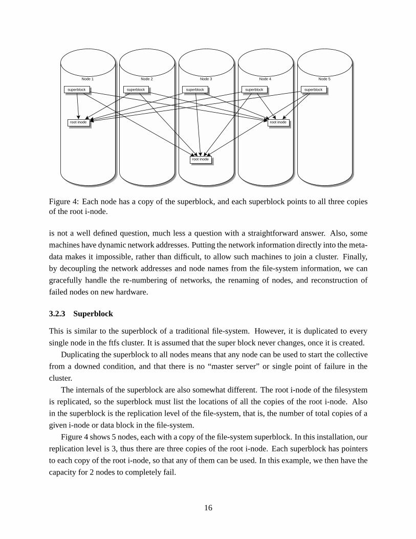
4 Each node has a copy of the superblock, and each superblock points to all three
copies of the root i-node. . . . .. . . . . . . . . . . . . . . . . . . . . . . . . . . 16
5 Field sizes (in bits) of ftfs disk pointer. . . . . . . . . . . . . . . . . . . . . . . . . 17
6 Structure of traditional ffs i-node – taken from [DeR].. . . . . . . . . . . . . . . . 18
7 An ftfs i-node is quite similar to an ffs i-node, but must allow for a variable amount
of disk pointers. . . . . . . . . . . . . . . . . . . . . . . . . . . . . . . . . . . . . 19
8 Overview of ftfs i-node layout. .. . . . . . . . . . . . . . . . . . . . . . . . . . . 20
9 Table comparing Replication Level, spaced used by disk pointers, and extra space
at the end of the i-node. . . . . .. . . . . . . . . . . . . . . . . . . . . . . . . . . 21
3

1 Introduction
One of the central philosophies of UNIX is that everything should support the semantics of being
accessible as a file. With that in hand, it follows that thefile-systemis a central component of any
UNIX derived system.
UNIX variants are currently employed with great success both in industry and academia due to
the reasonable amount of reliability and customizability existent in most implementations. How-
ever, as enterprises grow and all manner of organizations become more and more reliant on network
computing services, the scalability and fault tolerance of traditional UNIX networks will continue
to be stretched far beyond their original design.
To address these needs, several approaches have been taken. The most common, and most
widely deployed as of this writing, is the tried and true method of throwing more money at the
problem. Bigger machines with bigger disk arrays and faster network interfaces have been able
to keep up with the demands of network implementors in most situations thus far. However, a
major shortcoming of the “large centralized hi-capacity data server” has always been its single
point-of-failure nature. In addition, many of these systems are cost prohibitive even in minimal
configurations. Finally, almost all systems suffer from the same down-time conditions as a tra-
ditional machine. Rarely can the data-server function at near-full capacity if it must operate in a
degraded state, or during a period of maintenance.
Another approach which has become more popular of late is simple clustering and fail-over
services. Current designs are based around two or four identical UNIX servers sharing a large
traditional data store via a common FCAL or SCSI bus [Sil, Sunb]. The idea is that the machines
in the “cluster” monitor each other and if a machine fails, the remaining machine(s) masquerade as
the failed machine on the network (typically by taking on the IP addresses of the downed machine,
in addition to their own). This situation is less than desirable for a number of reasons. First and
foremost, the scalability of the solution is quite limited. There are associated capacity and fault
limits with any single-cabinet disk storage system. When the storage needs of the cluster grow
beyond the maximum capacity of the shared disk-store, the upgrade path is usually cost-prohibitive,
if it is even possible. Additionally, the level of fault tolerance is dictated by the underlying storage
medium, usually RAID-5. Most implementations have proprietary hardware which makes fault
management and detection opaque to the network administrator.
An additional problem with current cluster designs is the lack of reliability in the fail-over
mechanisms. While this is a technology that is continually improving, early versions of UNIX
clustering solutions would often detect failures incorrectly. Correctly functioning machines would
be incorrectly identified as down, and the remaining machines in the cluster would attempt to
takeover the resources of the presumed-failed machine. The fail-over mechanism was so problem-
atic and required so much human intervention that one customer discontinued it’s use entirely, and
returned to running their machines in a non-clustered fashion. This, combined with the compar-
4
atively long amount of time [Suna] required for a successful fail-over, make the current solutions
less than optimum
The need for a scalable and fault-tolerantfile-systemfor the UNIX platform should be evident.
As the computing load on popular web servers and departmental file and application servers goes
up, so does the need for scalability and the imperative for minimum down-time. If UNIX is to
make the transition to a properly-scalable distributed environment, it needs a distributed file-system
which can correctly and efficiently manage faults as well as growth.
To address these problems, we have designed a new filesystem,ftfs. The main contributions
of our research are scalability and fault tolerance. Other goals include use of non-specialized
hardware, low cost of deployment, and easy integration with current systems.
Keep in mind that we provide merely thedesignof ftfs. That is, we have not implemented ftfs,
as a proper implementatation would be well beyond the scope of an undergraduate thesis. Further-
more, as with any design, it should be expected that the design will evolve as an implementation
begins. Shortcomings will be found with our design which cannot be predicted until the time of
a given implementation. We have addressed the issues we are aware of currently, but there are
certainly issues which cannot be known until an implementation is attempted.
What wedo provide is enough to demonstrate that a serverless fault-tolerant distributed file-
system can be made for all practical purposes transparent to the user, and can be made without
significant redesign of existing operating systems.
Though we’ve spoken of UNIX environments here, nothing about the concepts in ftfs need
be tied to UNIX-like operating systems. In fact, the design we propose is general enough that
it can be applied to nearly any existing file-system architecture, perhaps without even modifying
existing code. This generality leaves much opportunity for further research, and much flexibility
in implementation.
The rest of this thesis is organized as follows. Section 2 discusses work related to our research.
Section 3 gives our design of ftfs, as well discussions of some of our design choices. Section
4 details possible applications for our research, and some background on how our research was
motivated. Section 5 provides a discussion of how the design of ftfs meets the goals we hoped
to acheive. Finally, Section 6 provides an overview of future work to be done, both in terms of
additional design decisions and actual implementation work.
2 Related Work
There have been many distributed file-systems in the past. While most file-systems themselves
don’t natively support fault tolerance, the underlying storage scheme can be made to be fault tol-
erant, and the file-system can either transparently benefit or can be made to specifically exploit
any underlying fault tolerance. However, to my knowledge there is no widely used file-system for
5

the UNIX environment which effectively combines both fault tolerance and a scalable distributed
nature.
The most commonly used distributed file-system in UNIX is the Network File System (NFS).
NFS has several advantages. It is simple to install, manage, and deploy. It can use any other
supported file-system as it’s backing file system. It is well supported across many different varieties
of UNIX, and there are NFS client packages for most versions of Microsoft Windows.
One problem with NFS is its fault tolerance. In an NFS scenario, there is a strong distinction
between the clients and the server. The server has all of the data, and services all the requests made
by the clients. This should make a few drawbacks immediately obvious. The NFS server is a single
point of failure1. Also, all file sharing traffic must go in and out of the NFS server. Some aspect
of that machine, be it the network, disk system, or CPU itself, will end up being an unconquerable
bottleneck which prevents further scalability [LB98].
Many efforts have been made to improve NFS and extend its usefulness beyond these shortcom-
ings. Sun Microsystems, the original designer and implementer of NFS, has a High-Availability
NFS solution [Sunb], based on a clustering scheme similar to the previously mentioned UNIX
clustering solutions. While this begins to address reliability, by providing redundant machines so
that at least one machine-fault can be tolerated, it suffers from the same scalability problems that
are inherent with general UNIX clustering; current implementations are extremely limited in the
number of supported nodes.
Recently there has been much research in improving various aspects of file-systems in the
UNIX environment. The focus of much of this research has been performance. Most BSD derived
UNIXes use theffsfile-system, which is an optimized version ofufs, the original UNIX file-system
[MBKQ96, Vah96]. SVR4 and the traditionally commercial UNIXes tend to have developed their
own file-systems, but these are typically expansions offfs.
One notable exception is Silicon Graphics, who in the mid 1990’s introducedXFS, which
is primarily distinguished from traditional UNIX file systems by its “journaled” or “log-based”
nature. XFS revisits the way file-system meta-data is recorded and used, and migrates the file-
system design motif away from the traditional christmas-tree of i-nodes UNIX approach and into
something resembling the way many RDBMS packages organize disks into extents and indexes.
Additionally, log-based file-systems utilize something analogous to an RDBMStransaction log
or journal which records the state oftransactions(changes to the file-system meta-data). This
fundamental change in file-system design has several key benefits, the most notable being the
massive improvement in file-system reliability and recovery. Unlike traditional UNIX file-systems,
which must use afsckutility to examine and repair the connectivity of the file-system tree in the
event of an improper shutdown of the operating system, a log based file-system can simply examine
the most recent events in the transaction log and compare them to the actual state of the disk1This has been addressed to some extent by [Sil, Sunb].
6

[MBKQ96, Vah96]. Incomplete transactions are “rolled back” (again similar to how an RDBMS
operates) and then the file-system is again consistent. This algorithm runs in what is effectively
constant time, since the size of the transaction log need not be related to the size of the file-system.
Comparatively,fsckon an i-node based file-system is a much slower process, requiring multiple
passes of orderO(n) of the file-system to be repaired.
Although XFS and other log-based file-systems have greatly enhanced file-system performance
and reduced downtime in the event of a failure, they do not have any inherent fault tolerance, nor
do they have any distributed features. Realizing this, Silicon Graphics has a product calledxlv,
the XFS Logical Volume Manager, which supportsplexingandstriping of XFS file systems. The
plexing functionality allows for fault tolerance within a single computer system, but employs full-
mirroring which requires twice the disk space of the non-fault tolerant solution. This can be cost
prohibitive, and typically in a mission critical situation, only the operating system files are on a
mirrored file-system. User data will typically be on a file-system which is inherently not fault
tolerant, but will reside on a disk unit which has hardware fault tolerance, such as a third party
RAID system.
Another interesting file-system of a similar name is the Berkeley xFS [ADN+95]. xFS is
distributed, and according to the xFS publications, is also the firstserverlessdistributed file-system.
Conceived as part of the BerkeleyNOWproject, which aims to build clustering and distributed
services on top of traditional UNIX, it is similar to SGI XFS in its journaled and performance
oriented nature. In xFS, all the members of the distributed system share a single unified view of the
file-system, and all members can be both a client and a server, although xFS need not be configured
that way [ADN+95]. xFS excels in scalability areas. It seems to exhibit linear performance gains
at least up to 32 connected nodes [ADN+95].
One area which xFS is currently weak in is fault tolerance. xFS was based on research done
by several previous projects. DASH [LLG+90], a protocol for distributed cache coherency in
large SMP machines, LFS, the Logging File System for BSD 4.4 [MBKQ96], and Zebra [HO95],
a file-system which employed networked RAID-5. xFS combines these technologies to have a
fully distributed, cache-coherent log-based file-system which uses parity drives in order to provide
tolerance of one fault.
While this approach to fault tolerance can give a considerable space savings over block-duplication,
it is limited in the number of faults it can handle, and is more limiting in where and how the fault
can occur. Fault tolerance does not appear to be a central design goal of xFS.
Also related to ftfs is the University of Minnesota GFS - the Global File-System [PBB+].
GFS is also a serverless distributed file-system. It has received funding from both government and
commercial sectors alike, including NASA Goddard Flight Cetner and Veritas Corporation (Veritas
sells a commercial high-performance file-system to various UNIX vendors). The GFS approach
relies on a new trend in computing called aStorage Area Network. In a SAN, multiple machines
7

are attached via Fiber Channel or SCSI bus to multiple disk device servers. The GFS requires
disk devices to support an additional set of commands in the SCSI-3 protocol, which at least one
hard disk manufacturer now supports. The foundation of GFS is this new addition to the SCSI-3
command set, which allows individual disk drives to support a form of distributed locking, which
the disk controllers and file-system software layer can manipulate.
GFS certainly acheives the distributed aspect of a distributed system, as many machines can be
attached to the SAN. However, this implementation is dependent on SAN hardware and disk drives
which support the Dlock protocol [PBB+]. Additionally, while the GFS papers mention fault tol-
erance ability [PBB+], it is not clear under what circumstances faults can be tolerated, and how
they are dealt with. This uncertainty of the fault-tolerance capability, and the requirement for a
well-defined hardware solution which implements the Storage Area Network make GFS unattrac-
tive for reliability and scalability reasons. Future work on GFS is slated to address the scalability
issue, by allowing machines to connect to a GFS via traditional IP. The idea is to virtually extend
the storage area network by encapsulating the protocol used on the SAN inside of IP packets for
purposes of communicating with the non-attached machines.
A more widely used distributed file-system is theAndrew File-System (AFS) [Vah96], designed
jointly by IBM and Carnegie-Mellon University. Design goals of AFS included scalability, UNIX-
compatability, fault-tolerance, and security.
In AFS, there are dedicated file-servers, which store the shared file data, and AFS clients.
AFS stricly enforces the client/server distinction. In fact, in AFS a node is either strictly a client
or strictly a server. Network congestion is avoided by network topology and data management.
AFS assumes the existance of an AFS server near each group of client machines. The “local”
AFS server is expected to have all of the data which its “local” clients require. However, when a
client requires a resource which is not on the nearby server, that request can go out over the larger
backbone network and be serviced by a more distant AFS server. Data can be migrated from one
server to another to help balance client loads. AFS relies on aggressive file caching and a stateful
protocol to reduce network traffic, and thus further improve performance. Client nodes in an AFS
file-system cache 64kbyte chunks of files they have recently accessed on their local disks. The
AFS servers maintain cache consistency by notifying clients of cache invalidations. Finally, the
AFS design further reduces server load by stipulating that name lookups are done on client nodes,
and that client nodes also cache directory heiarchies.
AFS is not a problem free file-system. First, AFS clients are required to have local disks to
cache data, which is always primarily stored elsewhere. There is no possibility of a diskless AFS
workstation, and client disk size becomes a factor in overall performance. Also, AFS servers must
be dedicated machines, and AFS performance relies heavily on an AFS server being “nearby”
in terms of network hops to the clients accessing its data. The implementation of AFS client-
side caching and cache coherence severely impacts the performance seen by clients. One study
8

demonstrated that even for data which was already locally cached, AFS was up to two times slower
than accessing a local file, due to its complicated cache management[Vah96]. Finally, the AFS
implementation doesn’t adequately implement UNIX file-system semantics, as changes to files are
only written back to the AFS server after the UNIXclose() system call. This leads to a great
deal of unpredictability and is extremely fault prone.
AFS does support a less painful process of data migration than some other file-system designs.
When data is moved from one AFS server to another, the original AFS server knows how to redirect
clients to the new location of the data. This alleviates the need for a uniform directory update taking
place on every AFS client and server in the system.
Overall, AFS has demonstrated that it is very scalable, especially over Wide Area Networks
(WANs), but that it has significant performance and reliability issues.
Despite the shortcomings of AFS, Transarc Corporation was able to take the AFS codebase and
create the DCE2 Distributed File-System, orDFS[Vah96].
DFS addresses many of the problems of AFS. Firstly, DFS is implemented in the UNIX vnode
layer. This allows a DFS server to also be a DFS client, i.e. data on a DFS server can be accessed
by users or processes on that same server, in addition of course to any other client or server in the
DFS.
DFS also provides much stronger consistency guarantees, and better implements UNIX file-
system semantics. It’s locking scheme has a much finer granularity than AFS, and locks are done
at theread()/write() level as opposed toopen()/close() .
DFS also has excellent availability features, as DFS filesets3 can be replicated to other DFS
servers. This also allows client read requests to be distributed amongst the various DFS servers
which all have copies of a fileset.
DFS inherits the scalability of AFS, and improves upon AFS in the areas of reliability and
UNIX integration. DFS can also provide some level of fault-tolerance. However, with DFS these
features come at a price, both monetarily and in terms of complexity. DFS is part of the Open
Software Foundation Distributed Computing Environment(OSF DCE). As such, it is typically
extremely expensive. Furthermore, it is not available on a wide variety of operating systems and
architectures. Finally, its complexity and integration into DCE requires that you be running DCE,
the DCE directory service, and DCE Remote Procedure Call services[Vah96].
Perhaps the most interesting distributed file-system is the Coda file-system[JS91]. It’s primary
distinguishing feature is that it supports disconnected operation, that is, a client can become dis-
connected from some or all of the file servers and still continue to operate on shared data. This is
acheived by controlled client caching, and an automatic reconnection mechanism that detects and
resolves conflicts upon reconnection to the file servers.2Distributed Computing Environment3A logical grouping of files and directories
9

Coda is an outgrowth of AFS, and as such it mandates the strong distinction between clients
and servers. Its scalability is thus similar to that of AFS. In [JS91], data is presented which shows
the occurances of multiple users modifying the same files within various time intervals, and finds
this to be extremely uncommon. However, this study was done on the CMU Computer Science
AFS servers, which show behavior atypical for many environments. Notably, like AFS, Coda
only does cache updating upon theclose() system call. Furthermore, the granularity of the
distribution is curently limited to entire files, although the authors acknowledge that this is an
area for future work. The Coda authors go on to mention that while Coda could conceivably
replace the AFS installation on their network, Coda’s primary feature is disconnected operation,
specifically useful in faulty networks, or with laptops which are voluntarily taken offline as their
users travel from location to location. Furthermore, server replication in Coda is available, but
is an afterthought and carry over from AFS. Coda is built on the assumption that there will be a
significant failure which prohibits continuously connected operation between clients and servers,
and is designed with this in mind. To effectively implement useful disconnected operation, users
must specify which files they want to be locally cached on their workstation with configuration
files. The coda cache manager then caches those files on the local drive, and should the client
become disconnected, will use the cached copies for all operations, including modifications, until
the client can reconnect to the server, where the client and server will negotiate synchronizing the
state of the file-system. Non-resolvable conflicts between the server and the client cache must be
resolved by human intervention.
Coda provides an intriguing and useful possibility for computer users on slow networks or who
frequently use laptops which access shared file-systems, however because of its manual data migra-
tion and large granularity, it is less than ideal for a distributed file-system focusing on managable,
scalable, cluster computing.
3 Design
The key to distributed computing in the UNIX environment is a file-system which is distributed,
reliable, and simple to integrate with a wide variety of current UNIX-like operating systems.
If the file-system is to be distributed, many machines must be able to utilize the file-systems
data in a convenient and familiar paradigm. This level of “distributedness” must scale well, that is,
as the number of nodes in the distributed environment goes up, the performance must not degrade
to the point that it is detrimental.
If the file-system is to be reliable, it must be able to tolerate a wide variety of faults and
provide seamless and uninterrupted data availability to the users. This implies that the cluster
must recognize and recover from disk failures, entire node failures, and network partitioning.
The last desirable aspect of a reliable distributed file-system is that it should be easy to integrate
10

with current UNIX environments. That means it shouldn’t require a major shift in how the file-
system is used, nor should it require a large monetary investment in advanced hardware.
We present the design of ftfs, a file-system which attempts to satisfy the above conditions. It
is hardware agnostic, requiring only common file-system and network services and semantics for
it to be implemented effectively. It provides a useful level of performance in a typical multi-user
distributed environment. Most of all, it tolerates a pre-determined number of disk or machine faults
with minor performance degradation as the only visible effect.
In much of this paper, for concreteness, we make an explicit comparison with the BSD UNIX
4.4 file-system,ffs [MBKQ96]. Our structures and even some of our file-system concepts out-
growths of the BSD file-system because we wanted a well understood and widely available code
and knowledgebase to start from. However, ftfs is not designed as an extension to BSD, instead
we feel that the design is general enough that it can be easily implemented using the best features
of a wide variety of modern file-systems. Again, our presentation here in terms of BSD concepts
is only for concreteness, and to show feasability.
The rest of this section is organized in the following manner. Section 3.1 gives an overview
of the design. Section 3.2 discusses the data structures that make up ftfs. Section 3.3 elaborates
on the layout of an ftfs file-system by describing the allocation mechanisms. In Section 3.4, we
introduce the operation of ftfs by discussing how a filesytem read occurs. In Section 3.5 we further
this by describing file-system writes. Section 3.6 discusses detecting faults, and the fault model
assumed by our design. Section 3.7 discusses the “rebalancing” algorithm, by which ftfs maintains
good utilization and load distribution. Next, Section 3.10 discusses how the file-system recovers
from various faults.
3.1 Overview
The major design paradigms of ftfs are distribution and replication. Reliability will be achieved by
replicating objects to avoid single points of failure. Given a proper replication strategy, and access
methods based on that replication strategy, we beleive a system can be designed to ben-way fault
tolerant.
Distribution goes hand in hand with replication. Distributing objects across the nodes in the
file-system collective should help implement a replication policy which has good fault tolerance
characteristics, and it should also improve scalability by de-centralizing all aspects of file-system
usage. While replication increases the bandwidth required for file-system writes, this increase is
a function of file-system replication level, and is independant of the number of nodes in the file-
system. Thus as the file-system is scaled when nodes are added, network utilization per-write
does not increase. Moreover, replication allows parallelization of reads, which tend to dominate
file-system access[Tan95].
To those ends, ftfs is designed to be “serverless”, as in figure 1. That is, in ftfs, there will be
11

NFS Server
NFSClient
NFSClient
NFSClient
NFSClient
ftfsClient/Server
ftfsClient/Server
ftfsClient/Server
ftfsClient/Server
ftfsClient/Server
Figure 1: The difference between NFS and the “serverless” approach. An arrow represents arequest for data.
no single point of failure. An ftfs file-system will be a loosly coupled network of machines, all
of which have some portion of the ftfs meta-data, and all of which will donate some portion of
their local diskspace to the ftfs “collective.” Each machine in an ftfs collective is both a client
and a server. In a typical configuration, each machine would reserve some partition of its local
disk space for ftfs block storage. No single machine would have all of the data blocks available
to it locally, and no single machine would have all of the file-system meta-data locally. However,
because each machine would have a copy of thesuperblock of the file-system, each node in the
collective knows which other nodes to talk to in order to successfully traverse the file-system meta-
data, and subsequently access the requested data block. At the user level, each machine in the ftfs
collective will appear to contain a large local file-system. While it is true thatsomeof the data
blocks of the ftfs file-system will be local to each node, it is expected that most of the data blocks
will need to be fetched over the network from other machines in the ftfs collective.
The distributed aspect of this file-system should be apparent. The ftfs implementation hides the
details from the user, who sees a local file-system larger than the local diskspace available. Every
other machine in the ftfs cluster has the same view of this file-system (although each machine need
not mount the file-system in the same place on their local tree).
The other significant aspect of ftfs is that each datablock, that is, a portion of data which is used
for storing data from actual operating system and user files (analagous to a block of a traditional
12

Node 1
superblock
Node 2
superblock
Node 3
superblock
Node 4
superblock
Node 5
superblock
root inode
root inode
root inode
directory/src
directory/src
directory/src
file foo.c
file foo.c
file foo.c
Figure 2: An example ftfs cluster with 5 nodes, and a replication level of 3.
file-system), as well as each directory block (part of the file-system meta-data), is duplicated mul-
tiple times throughout the collective, so that each data block appears on multiple different nodes.
The meta-data for the ftfs file-system then contains, among other things, a list of machines in the
collective where a given datablock can be found. The meta-data itself contains pointers to the
nodes wheremoreof the meta-data can be found, since the meta-data is also distributed and repli-
cated. By making a data placement policy who’s axiom is that the same block of data must be
written n times, and never more than once to the same node in the collective, we can guarantee
that the entire cluster will be able to surviven � 1 faults, wheren is the number of times a given
(and thus every) block exists in the collective.
Consider figure 2. We have 5 nodes in an ftfs cluster, which is configured for 2-way fault
tolerance. Thus, for each object in the file-system, 3 total copies exist. Any two nodes can fail,
without any loss of file-system availability. Notice that every object in the system has pointers
for all the copies of its immediate children. Notice that in this situation, no node stores all of the
required information to traverse from the superblock to the eventual file “/src/foo.c”. On the other
hand, every object in the file-system has the property that it can be accessed via three different
nodes.
A major complicating factor here is the asynchronous nature of distributed environments. In
a single machine, the local file-system code doesn’t need to worry about other kernels modifying
data and kernel structures; so long as the operating system doesn’t crash, file-system consistency
is guaranteed. With a distributed file-system, any node in the collective must be able to provide the
semantics of UNIX file access to any application. This requires things like file locking, which can
be complicated in a distributed system. Deadlock avoidance is a major issue.
Caching is what modern file-systems use to keep up with the rest of the system. However, a
13

major difficulty with massively-distributed designs is the issue of cache-coherency. That is, assume
that nodea and nodeb are both members of an ftfs collective. If nodea has a shared object cached,
and nodeb wants to modify that object, then nodea’s cache must somehow be invalidated. Silicon
Graphics alleviated this problem in hardware when designing their Origin series of scalable sym-
metric multi-processor machines. They used the algorithm for directory-based cache coherence
from the Stanford DASH4 [LLG+90] to handle distributed cache-invalidation efficiently. ftfs will
use a similar, if not exactly the same, mechanism as is employed by DASH.
Another difficulty, which affects everything mentioned above, is race conditions. Race condi-
tions happen when processes are logically sequential and non-interruptible, but are implemented
non-sequentially or interruptably. Multi-tasking operating systems and certainly distributed sys-
tems do not have physical sequentiality, and the rules governing when logical sequentiality is
upheld vary.
Consider a process which needs to verify a condition, then based on that condition perform
a task. In a sequential system, there is no problem. The operation isatomic. Now consider
a multi-tasking or distributed system. The process verifies the condition. It is suspended by the
scheduler, and another process is allowed to run which modifies the condition. The original process
is continued at its point of execution, after verifying the condition. The process’s state is restored,
and it believes that the condition it checked was correct, so it executes, incorrectly, the next step of
its task. The problem here is that atomicity was not preserved.
For a distributed file-system to have any chance of working correctly, atomic operations, as
required by higher level programming paradigms and semantics, must have their atomicity pre-
served. This is non-trivial, as it is a complicated issue even on SMP computers. Typically some
sort of locking is used to limit access to critical sections of code. However, in a distributed sys-
tem even performing the locking can cause race conditions. Thus, great care must be taken when
designing a locking scheme to ensure deadlock avoidance and fairness. For more on file-system
locking, see Appendix A.
3.2 Data Structures
Because ftfs must be easy to implement in a real operating system, its data structures should be
similar to those which are pre-existant in modern operating systems. However, as it is vastly more
complex than traditional filesystems, ftfs needs additional data structures as well as modifications
to the traditional ones.
In this subsection are overviews of the unique node identifier and node map, two data structures
that we introduce, and our modified versions of the superblock, diskpointer, and i-node, structures
we borrow and modify from conventional file-systems.4which Berkeley also used in the design of xFS
14

unique machine identifier partition block number
Figure 3: Structure of a ftfs disk pointer.
Breifly reviewing, the superblock of a file-system is the “starting point” of the file-system. This
data structure is typically at the beginning of physical disks and is of a known size at compile time.
The operating system looks here to determine the parameters of the file-system before completely
mounting the file-system for general use. The superblock is essential for the file-system to be
usable, as it stores the parameters the file-system was created with, along with other data required
for reading the structure of the file-system.
An “i-node” is an abbreviation for “index node”. Traditional UNIX file-systems, includingffs
are based on a tree design. The “i-nodes” in this tree store attributes that a file will only have one
of, such as creation time, file owner, and file size. In addition, i-nodes contain a list of the raw disk
blocks that make up the body of the data file. The i-node is an operating system structure; users are
rarely concerned with the contents of an i-node, as opposed to the contents of the file the i-node
identifies.
Finally, one of the very important fields contained in an i-node is a list of diskpointers. Disk-
pointers give the mapping from logical ranges of bytes of a file to block locations on the underlying
storage device. By using diskpointers, the operating system can present the abstraction of a file be-
ing a contiguous sequence of bytes, while in reality the file may have its data spread across many
different tracks of the disk, or in the case of ftfs, many different disks in a node, or even many
different nodes in a cluster.
3.2.1 Unique node identifier
The unique node identifier is a value which uniquely identifies a node in an ftfs cluster. Currently,
we propose a 16 bit unsigned value. This allows for216, or 65536 nodes in a cluster. Clearly, the
potential for ftfs to be vastly scalable exists.
3.2.2 Node map
The node map is a mechanism for managing which nodes are in a collective, their status, and their
disk resources. It is effectively, the “configuration file” for an instance of an ftfs filesystem. The
node map is primarily a way of corresponding network addresses with a unique node identifier.
File-system data is organized according to 3-tuples, as shown in figure 3. Thus, each member of
an ftfs collective must have a copy of the node map, so that it can correlate file-system information
with network addresses.
There are several reasons to not directly use network addresses in the file-system. For instance,
many machines have multiple network addresses. Choosing which one to place in the meta-data
15
Node 1
superblock
Node 2
superblock
Node 3
superblock
Node 4
superblock
Node 5
superblock
root inode root inode
root inode
Figure 4: Each node has a copy of the superblock, and each superblock points to all three copiesof the root i-node.
is not a well defined question, much less a question with a straightforward answer. Also, some
machines have dynamic network addresses. Putting the network information directly into the meta-
data makes it impossible, rather than difficult, to allow such machines to join a cluster. Finally,
by decoupling the network addresses and node names from the file-system information, we can
gracefully handle the re-numbering of networks, the renaming of nodes, and reconstruction of
failed nodes on new hardware.
3.2.3 Superblock
This is similar to the superblock of a traditional file-system. However, it is duplicated to every
single node in the ftfs cluster. It is assumed that the super block never changes, once it is created.
Duplicating the superblock to all nodes means that any node can be used to start the collective
from a downed condition, and that there is no “master server” or single point of failure in the
cluster.
The internals of the superblock are also somewhat different. The root i-node of the filesystem
is replicated, so the superblock must list the locations of all the copies of the root i-node. Also
in the superblock is the replication level of the file-system, that is, the number of total copies of a
given i-node or data block in the file-system.
Figure 4 shows 5 nodes, each with a copy of the file-system superblock. In this installation, our
replication level is 3, thus there are three copies of the root i-node. Each superblock has pointers
to each copy of the root i-node, so that any of them can be used. In this example, we then have the
capacity for 2 nodes to completely fail.
16
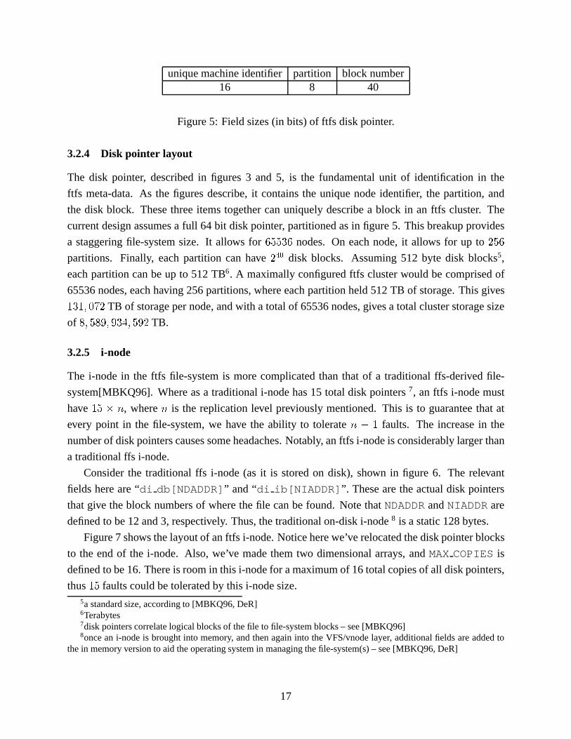
unique machine identifier partition block number16 8 40
Figure 5: Field sizes (in bits) of ftfs disk pointer.
3.2.4 Disk pointer layout
The disk pointer, described in figures 3 and 5, is the fundamental unit of identification in the
ftfs meta-data. As the figures describe, it contains the unique node identifier, the partition, and
the disk block. These three items together can uniquely describe a block in an ftfs cluster. The
current design assumes a full 64 bit disk pointer, partitioned as in figure 5. This breakup provides
a staggering file-system size. It allows for65536 nodes. On each node, it allows for up to256
partitions. Finally, each partition can have240 disk blocks. Assuming 512 byte disk blocks5,
each partition can be up to 512 TB6. A maximally configured ftfs cluster would be comprised of
65536 nodes, each having 256 partitions, where each partition held 512 TB of storage. This gives
131; 072 TB of storage per node, and with a total of 65536 nodes, gives a total cluster storage size
of 8; 589; 934; 592 TB.
3.2.5 i-node
The i-node in the ftfs file-system is more complicated than that of a traditional ffs-derived file-
system[MBKQ96]. Where as a traditional i-node has 15 total disk pointers7, an ftfs i-node must
have15 � n, wheren is the replication level previously mentioned. This is to guarantee that at
every point in the file-system, we have the ability to toleraten � 1 faults. The increase in the
number of disk pointers causes some headaches. Notably, an ftfs i-node is considerably larger than
a traditional ffs i-node.
Consider the traditional ffs i-node (as it is stored on disk), shown in figure 6. The relevant
fields here are “di db[NDADDR]” and “di ib[NIADDR] ”. These are the actual disk pointers
that give the block numbers of where the file can be found. Note thatNDADDRandNIADDRare
defined to be 12 and 3, respectively. Thus, the traditional on-disk i-node8 is a static 128 bytes.
Figure 7 shows the layout of an ftfs i-node. Notice here we’ve relocated the disk pointer blocks
to the end of the i-node. Also, we’ve made them two dimensional arrays, andMAXCOPIES is
defined to be 16. There is room in this i-node for a maximum of 16 total copies of all disk pointers,
thus15 faults could be tolerated by this i-node size.5a standard size, according to [MBKQ96, DeR]6Terabytes7disk pointers correlate logical blocks of the file to file-system blocks – see [MBKQ96]8once an i-node is brought into memory, and then again into the VFS/vnode layer, additional fields are added to
the in memory version to aid the operating system in managing the file-system(s) – see [MBKQ96, DeR]
17

struct dinode {u_int16_t di_mode; /* 0: IFMT, permissions; */
/* see below. */int16_t di_nlink; /* 2: File link count. */union {
u_int16_t oldids[2]; /* 4: Ffs: old user *//* and group ids. */
ino_t inumber; /* 4: Lfs: inode number. */} di_u;u_int64_t di_size; /* 8: File byte count. */int32_t di_atime; /* 16: Last access time. */int32_t di_atimensec; /* 20: Last access time. */int32_t di_mtime; /* 24: Last modified time. */int32_t di_mtimensec; /* 28: Last modified time. */int32_t di_ctime; /* 32: Last inode change time. */int32_t di_ctimensec; /* 36: Last inode change time. */ufs_daddr_t di_db[NDADDR]; /* 40: Direct disk blocks. */ufs_daddr_t di_ib[NIADDR]; /* 88: Indirect disk blocks. */u_int32_t di_flags; /* 100: Status flags (chflags). */int32_t di_blocks; /* 104: Blocks actually held. */int32_t di_gen; /* 108: Generation number. */u_int32_t di_uid; /* 112: File owner. */u_int32_t di_gid; /* 116: File group. */int32_t di_spare[2]; /* 120: Reserved; */
/* currently unused */};
Figure 6: Structure of traditional ffs i-node – taken from [DeR].
18

#define MAX_COPIES 16
struct ftfs_dinode {u_int16_t di_mode; /* 0: IFMT, permissions; */
/* see below. */int16_t di_nlink; /* 2: File link count. */union {
u_int16_t oldids[2]; /* 4: Ffs: old user *//* and group ids. */
u_int32_t inumber; /* 4: Lfs: *//* inode number. */
} di_u;u_int64_t di_size; /* 8: File byte count. */int32_t di_atime; /* 16: Last access time. */int32_t di_atimensec; /* 20: Last access time. */int32_t di_mtime; /* 24: Last modified time. */int32_t di_mtimensec; /* 28: Last modified time. */int32_t di_ctime; /* 32: Last inode change time. */int32_t di_ctimensec; /* 36: Last inode change time. */u_int32_t di_flags; /* 40: Status flags (chflags). */int32_t di_blocks; /* 44: Blocks actually held. */int32_t di_gen; /* 48: Generation number. */u_int32_t di_uid; /* 52: File owner. */u_int32_t di_gid; /* 56: File group. */u_int32_t di_spare[2]; /* 60: Reserved; */
/* currently unused */
/* the disk pointers start at offset 68 */
ftfs_daddr_t di_db[NDADDR][MAX_COPIES];/* Direct disk blocks. */ftfs_daddr_t di_ib[NIADDR][MAX_COPIES];/* Indirect disk blocks. */
/** we fill out the remainder of the inode with* the start of the file this rounds up the size* of the inode, and helps for small files*/
};
Figure 7: An ftfs i-node is quite similar to an ffs i-node, but must allow for a variable amount ofdisk pointers.
19

Traditional i-node data
variable length chunk of disk pointers(corresponding dependant on replication level,
set at file-system creation time)
remainder of inode space filled with beginning offile data
2048bytes
Figure 8: Overview of ftfs i-node layout.
Realize that while this i-node is presented as a standard header file, it is more meant to represent
the on-disk layout of the i-node. In reality, the superblock will contain the value ofMAXCOPIES,
and the number of actual disk blocks in a given i-node will be determined at file-system creation
time.
Thus, the basic size of an i-node is not known at compile time. However, here we have defined
MAXCOPIESto be 16. The astute reader may have noticed that we’ve changed the type of a disk
block toftfs daddr t , which currently is defined as an unsigned 64 bit integer. Thus, the basic
size of this i-node is 1988 bytes. This is astronomically large compared to the 128 byte ffs i-node.
It also may first seem quite space inefficient. We realize that not every site will want the ability to
tolerate15 faults on a given file-system. Furthermore, file-system structures are generally in units
which are powers of two. Thus, we’ve made the size of an i-node 2048 bytes. This gives enough
room forupto15-way fault-tolerance, and has some room left over.
In the event that a file-system is created with 15-way fault tolerance9, there will still be2048�
1988 = 60 bytes left over in the i-node. If a site decides to use less copies of the disk pointers, as
we expect many will, there will be significantly more extra space. We’ve decided that this extra
space can be used to store the beginning of the actual file data. In this way, we get good utilization
of the i-node space regardless of the amount of replication in the file-system. Also, for small
files, no file blocks are needed at all, and the entire file can fit inside an i-node. This has obvious
performance benefits, as further disk reads and network traffic are avoided.
Figure 8 gives a higher level overview of an ftfs i-node, and how it is “partitioned” into three
main areas. We see that no matter what the file-system’s replication level is set at, the i-node makes9utilizing all 16 copies of the disk pointers
20

Replication Level space used extra space1 188 18602 308 17403 428 16204 548 15006 788 12608 1028 102010 1268 78012 1508 54014 1748 30016 1988 60
Figure 9: Table comparing Replication Level, spaced used by disk pointers, and extra space at theend of the i-node.
efficient use of space. Figure 9 shows a table correlating the replication level to the internal space
usage of the i-node. It is clear that each additional level of replication adds 120 bytes of disk
pointers to the i-node. By the time we have the full 16 copies, we can only fit the very smallest
files inside the i-node’s remaining free space. However, files larger than this will just have disk
blocks allocated to them. The inclusion of file data in the i-node is simply an optimization that
helps small files; it does not penalize file size nor does it penalize large files.
3.2.6 Disk layout
Other than the larger i-node sizes mentioned in Section 3.2.5, the on disk representation of data in
individual nodes is largely unimportant. ftfs only cares which nodes have a given object, and where
on those nodes the object is stored. Allocation, free space management, and maximizing disk-
based file-system performance are handled identically to the best solutions modern non-distributed
file-systems have to offer. For instance, retaining the BSD ffs example, we can employ the cylinder
group concept to have good intra-disk survivability and avoid fragmentation problems[MBKQ96].
The only change necessary to the on-disk structures of ffs would be the increased i-node and
superblock size. However, these details are irrelevant to ftfs. We could just as well come up with
a completely new way of storing on disk data. However, by not making a specification, we allow
for flexibility in implementation. In fact, it should be possible to implement ftfs as a stackable
VFS layer10 on top of ffs, or any other file-system for that matter. A large file could be made on a
traditional file-system, which simulated a linear group of disk blocks. The ftfs meta-data storage
could then be implemented as a separate file, again on a traditional file-system.
Ideally, for maximum performance, ftfs would use raw disk interfaces and have its own highly10VFS stands for Virtual File-System. It is the object oriented architecture that many UNIX kernels employ to
support multiple types of file-systems. See [MBKQ96] for more details.
21
efficient on-disk representation, perhaps utilizing journaling and other recently developed tech-
niques. However, regardless of the underlying storage mechanisms, ftfs will still have the same
fault-tolerance and scalability features. We consider this to be not only an advantage, but an ele-
ment of good design.
3.3 Allocation Algorithm
A major complication of a distributed file-system being serverless is that the allocation algorithm
must be distributed. In ftfs, which relies on active replication [Tan95] to acheive redundancy
and fault-tolerance, any node can initiate the allocation process, since any node presumably can
generate a request for a file-system write.
Designing a distributed allocator is a topic large enough for its own thesis. Our initial efforts
were focused on designing an algorithm that, given the number of nodes in a cluster, and the sizes
of their disks, could reliably predict wheren � 1 additional copies of a given block should be
placed throughout the cluster. The advantages of being able to calculate the position of any copies
from knowing the location of the original are tremendous. Only minor changes to the traditional
small UNIX i-node would be required. Smaller disk pointers could be used.
However, this does not lend itself well to perfect fault tolerance. Assuming perfect meta-data
integrity, such a scheme would work well and be wonderfully efficient. However, in the event of
metadata corruption, all copies are lost. Such a policy would needsomesort of way of replicating
information so as to guarantee safety from data loss.
Focusing on maximum fault survivability, we decided to make the meta-data massively redun-
dant as well. Thus, the allocator is significantly less complex, as any block for any item can go
anywhere. The only invariant is that there can never be more than one copy of a given object on a
given node, that is, if objectl must existn times in the system (in order to surviven � 1 faults),
then objectl must be onn differentnodes. The allocator we present here is most likely not optimal.
It is designed to provide fault tolerance, and to be correct.
Thus far, the design of ftfs has extended the traditional ffs where necessary to provide new
features. The allocation mechanism is similarly an extension. The design of ffs is based on perfor-
mance observations from the original s5fs11. In ffs, the allocator takes advantage of ffs’s cylinder
groups to avoid fragmentation and to manage free space.
Again, for concreteness of example, ftfs can extend this scheme. Assume a given node’s disk
very much resembles a standard ffs disk. When a new object must be allocated, the node initiating
the write selects then nodes that will hold copies of the object. Those nodes then perform their own
local allocations, and report back to the node that initiated the write with the necessary information.
To see this in action, consider the example of five nodes, with a replication level of three. We’ll
call the five nodesa; b; c; d; e, respectively. Nodea generates an allocation request.11Described in [MBKQ96]
22

� Nodea generates an alloc request. Nodea sets a lock for the parent object of the object we
are allocating. This lock locks all instances of that object in the cluster (3 total copies).
� Nodea uses an algorithm12 to select 3 nodes for copies of the new object to reside on.
Assume that nodesb; d, ande are selected.
� Nodea sends allocate messages tob; d, ande.
� Nodesb; d, ande perform allocations on their own local disk space. Each node keeps track
of which blocks it uses for local allocation.
� Upon completing each individual allocation, each individual node will respond toa with the
diskpointer (or other information) used on that particular node.
� As a receives answers from each node, it updates the parent object (which must point to this
newly allocated data). Sincea already holds locks on each copy of this object, it can safely
modify the necessary parent objects.
� Assumingb; d, ande all report back correctly,a can release the locks on the parent objects
and exit the allocation routine.
Note that the last step of this algorithm assumes thatb; d, ande all complete their allocations
correctly, and report back toa within some time interval. In other words, this interaction assumes
no faults. In the event of a fault, and to guarantee correctness, significant additional steps must be
taken to guarantee correctness. Some of these issues are addressed in Section 3.6.
3.4 File-System Reads
Since the most common filesystem operation is a read, consider at a high level how an ftfs filesys-
tem read will flow. The user program initiates a request to access something which is on an ftfs
filesystem. The operating system goes to service this request, and seeing that the requested object
resides on an ftfs filesystem, uses the appropriate ftfs-specific service routines. Neglecting caching,
the ftfs layer must decide where to get the data from.
Below we give a detailed example of a file-system read operation. A ftfs file-system is mounted
somewhere on a machine’s file-system tree. A user or process wants to read the file/home/mevans/src/f.c .
In this example,/home is an ftfs file-system. We give a detailed description of how the read op-
eration takes place13.
Note that for this example, locking and caching are ignored. Caching is addressed in Appendix
C and locking is discussed in Appendix A.12See Appendix B for comments on selection algorithms13For a very detailed example of the same operation on a traditionalffs file-system, see [MBKQ96], Ch 7.3
23
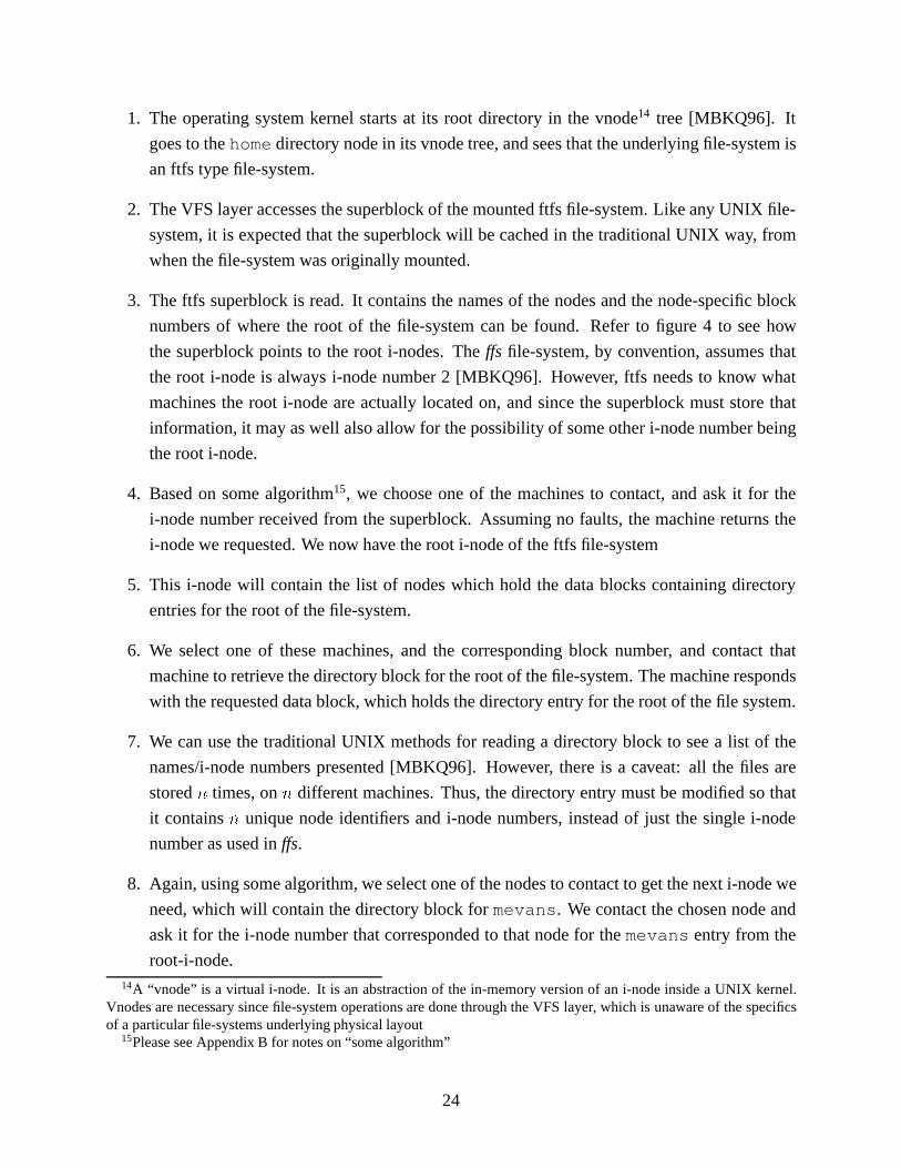
1. The operating system kernel starts at its root directory in the vnode14 tree [MBKQ96]. It
goes to thehomedirectory node in its vnode tree, and sees that the underlying file-system is
an ftfs type file-system.
2. The VFS layer accesses the superblock of the mounted ftfs file-system. Like any UNIX file-
system, it is expected that the superblock will be cached in the traditional UNIX way, from
when the file-system was originally mounted.
3. The ftfs superblock is read. It contains the names of the nodes and the node-specific block
numbers of where the root of the file-system can be found. Refer to figure 4 to see how
the superblock points to the root i-nodes. Theffs file-system, by convention, assumes that
the root i-node is always i-node number 2 [MBKQ96]. However, ftfs needs to know what
machines the root i-node are actually located on, and since the superblock must store that
information, it may as well also allow for the possibility of some other i-node number being
the root i-node.
4. Based on some algorithm15, we choose one of the machines to contact, and ask it for the
i-node number received from the superblock. Assuming no faults, the machine returns the
i-node we requested. We now have the root i-node of the ftfs file-system
5. This i-node will contain the list of nodes which hold the data blocks containing directory
entries for the root of the file-system.
6. We select one of these machines, and the corresponding block number, and contact that
machine to retrieve the directory block for the root of the file-system. The machine responds
with the requested data block, which holds the directory entry for the root of the file system.
7. We can use the traditional UNIX methods for reading a directory block to see a list of the
names/i-node numbers presented [MBKQ96]. However, there is a caveat: all the files are
storedn times, onn different machines. Thus, the directory entry must be modified so that
it containsn unique node identifiers and i-node numbers, instead of just the single i-node
number as used inffs.
8. Again, using some algorithm, we select one of the nodes to contact to get the next i-node we
need, which will contain the directory block formevans . We contact the chosen node and
ask it for the i-node number that corresponded to that node for themevans entry from the
root-i-node.14A “vnode” is a virtual i-node. It is an abstraction of the in-memory version of an i-node inside a UNIX kernel.
Vnodes are necessary since file-system operations are done through the VFS layer, which is unaware of the specificsof a particular file-systems underlying physical layout
15Please see Appendix B for notes on “some algorithm”
24
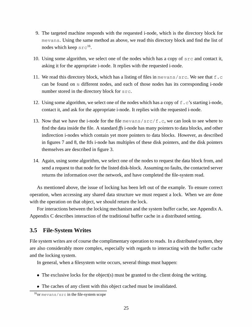
9. The targeted machine responds with the requested i-node, which is the directory block for
mevans . Using the same method as above, we read this directory block and find the list of
nodes which keepsrc 16.
10. Using some algorithm, we select one of the nodes which has a copy ofsrc and contact it,
asking it for the appropriate i-node. It replies with the requested i-node.
11. We read this directory block, which has a listing of files inmevans/src . We see thatf.c
can be found onn different nodes, and each of those nodes has its corresponding i-node
number stored in the directory block forsrc .
12. Using some algorithm, we select one of the nodes which has a copy off.c ’s starting i-node,
contact it, and ask for the appropriate i-node. It replies with the requested i-node.
13. Now that we have the i-node for the filemevans/src/f.c , we can look to see where to
find the data inside the file. A standardffs i-node has many pointers to data blocks, and other
indirection i-nodes which contain yet more pointers to data blocks. However, as described
in figures 7 and 8, the ftfs i-node has multiples of these disk pointers, and the disk pointers
themselves are described in figure 3.
14. Again, using some algorithm, we select one of the nodes to request the data block from, and
send a request to that node for the listed disk-block. Assuming no faults, the contacted server
returns the information over the network, and have completed the file-system read.
As mentioned above, the issue of locking has been left out of the example. To ensure correct
operation, when accessing any shared data structure we must request a lock. When we are done
with the operation on that object, we should return the lock.
For interactions between the locking mechanism and the system buffer cache, see Appendix A.
Appendix C describes interaction of the traditional buffer cache in a distributed setting.
3.5 File-System Writes
File system writes are of course the complimentary operation to reads. In a distributed system, they
are also considerably more complex, especially with regards to interacting with the buffer cache
and the locking system.
In general, when a filesystem write occurs, several things must happen:
� The exclusive locks for the object(s) must be granted to the client doing the writing.
� The caches of any client with this object cached must be invalidated.16or mevans/src in the file-system scope
25

� The data must be written to each node holding a copy of the object(s).
� Positive responses must be received from each node holding a copy of the object(s).
� The client frees its exclusive locks.
Mirroring the example given in Section 3.4, consider a write operation on the file
/home/mevans/src/f.c . Here, we pay attention to locking and caching issues, as they be-
come very important when doing writes in a distributed environment.
1. The operating system kernel starts at its root directory in the vnode17 tree [MBKQ96]. It
goes to thehomedirectory node in its vnode tree, and sees that the underlying file-system is
an ftfs type file-system.
2. The VFS layer accesses the superblock of the mounted ftfs file-system. Like any UNIX file-
system, it is expected that the superblock will be cached in the traditional UNIX way, from
when the file-system was originally mounted.
3. The ftfs superblock is read. It contains the names of the nodes and the node-specific block
numbers of where the root of the file-system can be found. Refer to figure 4 to see how
the superblock points to the root i-nodes. Theffs file-system, by convention, assumes that
the root i-node is always i-node number 2 [MBKQ96]. However, ftfs needs to know what
machines the root i-node are actually located on, and since the superblock must store that
information, it may as well also allow for the possibility of some other i-node number being
the root i-node.
4. Based on some algorithm18, we choose one of the machines to contact, and ask it for the
i-node number received from the superblock. Assuming no faults, the machine returns the
i-node we requested. We now have the root i-node of the ftfs file-system
5. This i-node will contain the list of nodes which hold the data blocks containing directory
entries for the root of the file-system.
6. We select one of these machines, and the corresponding block number, and contact that
machine to retrieve the directory block for the root of the file-system. The machine responds
with the requested data block, which holds the directory entry for the root of the file system.
7. We can use the traditional UNIX methods for reading a directory block to see a list of the
names/i-node numbers presented [MBKQ96]. However, there is a caveat: all the files are
storedn times, onn different machines. Thus, the directory entry must be modified so that17see footnote in Section 3.418Please see Appendix B for notes on “some algorithm”
26

it containsn unique node identifiers and i-node numbers, instead of just the single i-node
number as used inffs.
8. Again, using some algorithm, we select one of the nodes to contact to get the next i-node we
need, which will contain the directory block formevans . We contact the chosen node and
ask it for the i-node number that corresponded to that node for themevans entry from the
root-i-node.
9. The targeted machine responds with the requested i-node, which is the directory block for
mevans . Using the same method as above, we read this directory block and find the list of
nodes which keepsrc 19.
10. Using some algorithm, we select one of the nodes which has a copy ofsrc and contact it,
asking it for the appropriate i-node. It replies with the requested i-node.
11. We read this directory block, which has a listing of files inmevans/src . We see thatf.c
can be found onn different nodes, and each of those nodes has its corresponding i-node
number stored in the directory block forsrc .
12. At this point, we must do some locking. In order to write tof.c , we must make sure we
have exclusive access tof.c . To guarantee that no other node can modifyf.c while we are
using it, we must get a lock fromeachof then nodes which have copies off.c ’s i-node. To
avoid deadlock, our locking algorithm must use some deadlock-avoidance scheme20 when
acquiring each individual lock from then nodes.
Once we have been granted the exclusive write-locks for alln copies of the i-node, we can
proceed. Other nodes attempting to lock this i-node will have their lock requests denied until
we “return” the lock, or, in the event of a failure, it is determined that the node holding the
locks has failed.
13. If we are going to be modifying on disk data, then we’ll need to invalidate cached copies of
that data, cluster wide. Traditional systems might require a broadcast to every node in the
cluster at this point, however, using a directory cache algorithm21, we already know which
nodes, if any, have cached the data that we’ve modified. With this knowledge, we can guar-
antee that only nodes which need to do cache invalidations are contacted with an invalidation
message. Thus, if there are any invalidations which are to be performed, it is expected that
they will be a small subset of the total cluster. This should limit the performance penalty due19or mevans/src in the file-system scope20See Appendix A21See Appendix C and [LLG+90, LL, ADN+95] for more on directory cache schemes and implementations
27

to cache invalidation, certainly enough to keep caching an overall positive attribute of the
file-system.
While cache invalidation is donebeforethe actual write in this example, it may be possible
to do cache invalidation in parallel. This depends on the desired semantics of the implemen-
tation.
14. We can now write modifications to either the data blocks or the i-node of the file. However,
we must replicate our changes on each of then machines with copies of that data item.
In the event that we need to write additional data that requires an allocation, we’ll need to
call our distributed allocator, while still holding the locks for this object. As locking has the
granularity of i-nodes, this should not conflict with the allocator at all.
15. To be sure that we’ve correctly updated the file-system, we should make sure to receive an
acknowledgement of write completion from each of then nodes. While this is non-buffered
writing, it is important that writes be immediate to help maintain system-wide integrity.
Journaling techniques or weak consistency models may improve this facet in the future.
16. With all the acknowledgements received, the writes are complete, and we can free the locks
we hold.
It should be apparent that many of the steps mirror the read operation described in Section 3.4.
3.6 Detecting Faults
In order for the file-system to handle faults gracefully, it must be able to detect them. For ftfs,
we assume faults to be fail-silent, as opposed to byzantine[Tan95]. That is, once something goes
wrong with a node, it just stops responding to requests. On the other hand, a byzantine fault would
continue responding to requests, but return incorrect answers. While we can envison a scenario
where an ftfs node might return incorrect results, this should be the result of programming errors,
which can be detected and corrected. Furthermore, in [Tan95], it was shown that2n+ 1 nodes are
required to providen-way fault tolerance in the presence of byzantine faults. Finally, it has been
our observation that in general, a file server gives a correct answer, or no answer—but never the
incorrect answer.
Thus, when detecting faults, the issue becomes how to tell when a node has failed. Namely,
a node has failed when it fails to respond to a request from some other node(s). The level of
failure can be either transient, or permanant22. We assume that our communications link is reli-
able. Reliable communications layers do exist, so this is a reasonable assumption. Thus, when22In [Tan95], intermittent faults are also discussed; we group these with transient faults.
28

we have guaranteed message delivery, we can put timers on critical requests and glean a useful
approximation of a node’s “alive” status.
Generally, there is no way to differentiate between a transient fault and a permanant fault
using only one message. Although our transport is reliable, a node could simply be too busy to
respond before the message sender becomes impatient and contacts some other node for the same
information. Consider nodesa; b, and c. Nodea sends a request to nodeb. Nodeb receives
the message, but queues it because it has an extremely high load. Nodea expects a reply from
nodeb in a reasonable amount of time, but does not get one. Nodea makes a note of this, and
resubmits its request to some other nodec, which has a copy of the objecta wanted fromb. Node
c responds and nodea can go about its business. At some later time, nodeb may or may not get
around to processing its queue of messages. Ifb doessend a message back to nodea, a can make
the assumption that nodeb has not failed. Ifb never sends back a message toa, we still cannot
be sure of nodeb’s status. At some point, we must simply decide “nodeb is effectively down”.
Usually, this will be after several messages have been sent tob over a reasonable time interval, and
b hasn’t responded to any of them. The number of messages and allowable time limit should be
configurable based on the network environment and average utilization of the nodes. For the best
results, the other nodes in the cluster should come to a consensus about the status of a presumed
down node. If nodea cannot receive replies from nodeb, but nodec can, then clearly there is a
network fault. Several consensus and voting algorithms are mentioned in [Tan95].
In summary, when a majority of nodes do not receive a message after several attempts from a
given node, that node can be assumed as having permanantly failed. Manual intervention from the
system administrator will be required to restore it.
Note that it should be possible for a node to “fault itself”. Consider a node which detects
physical media errors during a file read. Traditional operating systems will notify the system
administrator of this condition and retry the operation (assuming it is retryable). If a node is
performing an operation and detects any sort of localized fault, in the interest of not creating a
byzantine condition, it should not blindly return a result to the rest of the cluster. At this point, the
node can either declare itself unhealthy and send a message to other nodes in the cluster saying so,
and then stop responding to requests, Or, perhaps preferably, the node can request that a vote take
place. Since a read request being made of a node can be made ton � 1 other nodes, those other
n � 1 nodes should be contacted to determine the correctness of the “failed” node’s answer. By
recording the results of these votes, and by keeping a watchful eye on the standard error logs of the
various nodes, a system administrator can determine the overall “health” of the system. If a node
repeatedly has the only dissenting opinion in a vote, and is also reporting media errors on its local
drives, the prudent administrator will work quickly to physically repair that node.
Clearly there are many possibilities in classifying faults and then taking the appropriate action.
The selection of a consensus algorithm is important. It should of course be serverless, and should
29

run in a reasonable amount of time, even on clusters with a large number of nodes. The importance
of expedience is lessened if the algorithm doesn’t block other parts of the file-system operation,
i.e. if it can run in parallel with file-system operations which do not affect the node in question.
3.7 File-System Rebalancing
An important part of the ftfs collective operation is the rebalancing algorithm. As nodes with free
disk space are added to the cluster, existing data should be “rebalanced” onto these nodes. That is,
copies of objects should be moved off of nearly-full nodes and placed onto the new empty nodes.
This improves load distribution.
As rebalancing is a potentially time consuming operation, and one that need not be run often,
it is best implemented as a userland process. Conditions for frequency of how often it is run will
vary from site to site, the point being that it is left to the administrator to decide when rebalancing
should be employed.
The basic operation of the rebalancing algorithm is as follows:
� Determine how much data should be placed on the new node.
� While the new node has less than this amount of data:
� Find the node which has the most diskspace utilized
� Select an object, which this node stores a copy of, and that the target node does not
already have a copy of.
� Get an exclusive lock on all copies of this object, in addition, get an exclusive lock on
all copies of the parent object of this object
� Copy the object to the new node, verify the copy, and delete the object from the node it
was moved off of
� Update the parent object so that it reflects the new location of its child (this object)
� release all locks
� End
Obviously, this doesn’t address the possibility of the most utilized node not having any blocks
which can be migrated to the new node, although we believe that possibility to be quite slim. In
such an event, the algorithm should pick a new node to move data off of, and tell the system
administrator to buy more new nodes!
30
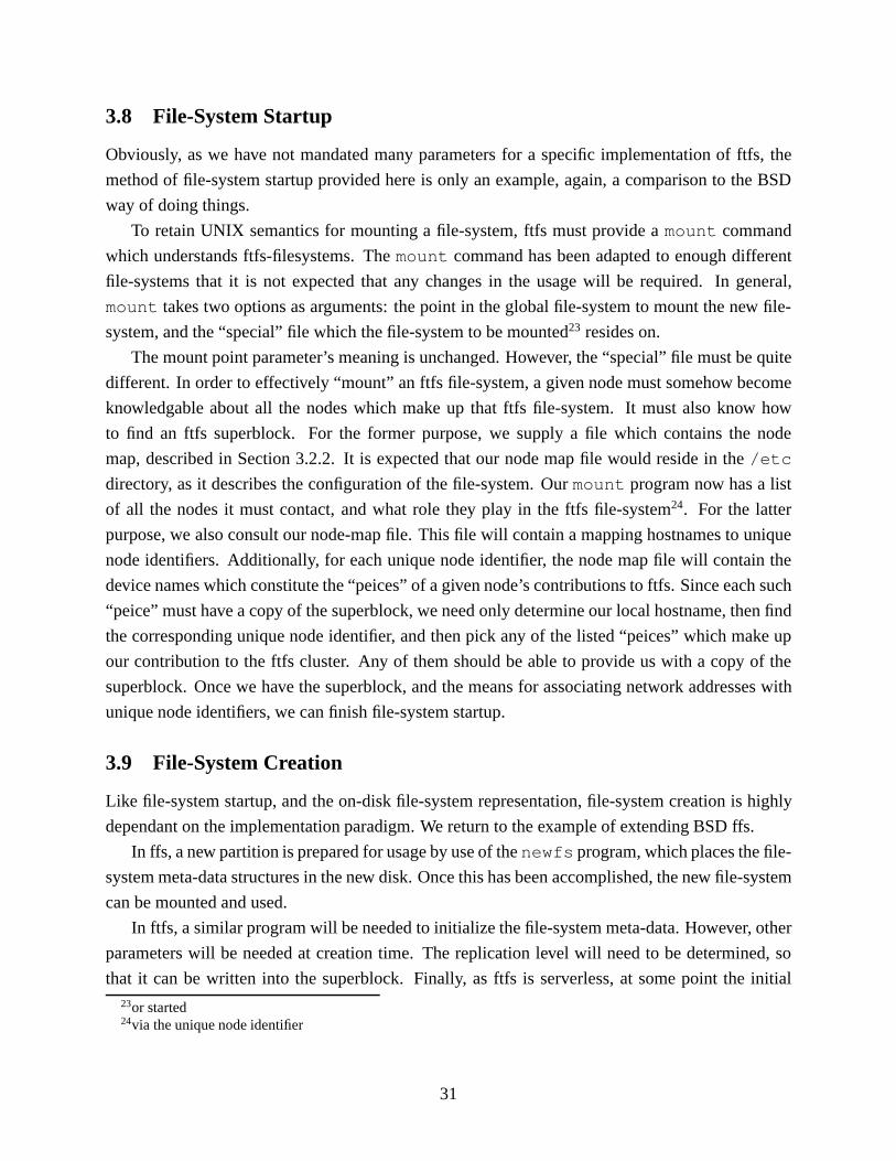
3.8 File-System Startup
Obviously, as we have not mandated many parameters for a specific implementation of ftfs, the
method of file-system startup provided here is only an example, again, a comparison to the BSD
way of doing things.
To retain UNIX semantics for mounting a file-system, ftfs must provide amount command
which understands ftfs-filesystems. Themount command has been adapted to enough different
file-systems that it is not expected that any changes in the usage will be required. In general,
mount takes two options as arguments: the point in the global file-system to mount the new file-
system, and the “special” file which the file-system to be mounted23 resides on.
The mount point parameter’s meaning is unchanged. However, the “special” file must be quite
different. In order to effectively “mount” an ftfs file-system, a given node must somehow become
knowledgable about all the nodes which make up that ftfs file-system. It must also know how
to find an ftfs superblock. For the former purpose, we supply a file which contains the node
map, described in Section 3.2.2. It is expected that our node map file would reside in the/etc
directory, as it describes the configuration of the file-system. Ourmount program now has a list
of all the nodes it must contact, and what role they play in the ftfs file-system24. For the latter
purpose, we also consult our node-map file. This file will contain a mapping hostnames to unique
node identifiers. Additionally, for each unique node identifier, the node map file will contain the
device names which constitute the “peices” of a given node’s contributions to ftfs. Since each such
“peice” must have a copy of the superblock, we need only determine our local hostname, then find
the corresponding unique node identifier, and then pick any of the listed “peices” which make up
our contribution to the ftfs cluster. Any of them should be able to provide us with a copy of the
superblock. Once we have the superblock, and the means for associating network addresses with
unique node identifiers, we can finish file-system startup.
3.9 File-System Creation
Like file-system startup, and the on-disk file-system representation, file-system creation is highly
dependant on the implementation paradigm. We return to the example of extending BSD ffs.
In ffs, a new partition is prepared for usage by use of thenewfs program, which places the file-
system meta-data structures in the new disk. Once this has been accomplished, the new file-system
can be mounted and used.
In ftfs, a similar program will be needed to initialize the file-system meta-data. However, other
parameters will be needed at creation time. The replication level will need to be determined, so
that it can be written into the superblock. Finally, as ftfs is serverless, at some point the initial23or started24via the unique node identifier
31

nodes the file-system is created with must be told about each other, so that the root i-node copies
can be created and the file-system can be started.
The initial approach would be to make thenewfs program as simple as possible, handling only
a single node. Once it had been run on each node of the initial cluster, the system administrator
would construct the initial node map25. At this point, the portion of the ftfs implementation which
handled network communication would need to be started, and told to listen for requests on each
node. Finally, some node would propogate the node map to all the nodes in the cluster, and create
the initial distributed meta-data, such as the root i-node copies. At this point, the node map could
be copied to each machine, and the ftfs file-system could be mounted.
3.9.1 Managing Nodes
Once an ftfs file-system is up and running, nodes can be added or upgraded at any time. If a new
node is to be added, the cluster needs only to be told of its existance by having a new entry inserted
into the node map. This requires a new unique node identifier, and a pre-formatted partition on the
new node, so that it may provide storage to the other cluster members.
After the node has been added, the administrator can choose to rebalance26 the file-system to
populate the new node, or she can rely on the allocation mechanism to gradually populate the new
node through osmosis.
3.9.2 Determining free space
In general, we can measure the free space on the file-system by adding up the free-space on each
of the partitions on all of the nodes. However, this value does not reveal how much additional data
can be written to the file-system, as we must maintain the policy that objects exist onn different
nodes. Thus, we needn total blocks, 1 on each ofn nodes, to write a block of data. We cannot
simply divide the number of total free blocks byn, as any node which had a disproportionately
large amount of free blocks would artificially inflate the value. We can, however, say that the total
free blocks on all nodes, divided byn constitutes an upper bound of the available space. On the
other hand, we can calculate a lower bound as well. Ifeverynode in the cluster hask free blocks
available, then we know that atleastk blocks can be written, regardless of replication level27.
Furthermore, ifm represents the number of nodes, then we can writebmnck blocks, since any
block can reside on any node which does not already have a copy of that block.
Between these two boundaries is the actual amount of usable space for writing additional data
to the file-system. Finding the best way to distribute data to optimally fill a file-system’s remaining
disk blocks is an optimiation problem in and of it self. Consider the problem:25described in Section 3.2.226see Section 3.727so long as the replication level is less than or equal to the number of nodes in the cluster.. however, this is strictly
a requirement and can never be violated.
32

Givenk nodes, and a replication level ofn, calculate the optimal way to fill
�k
i=0freei
blocks, wherek � n, andfreei is the number of free blocks on nodei. However,
the final restriction is that each block written must haven � 1 additional copies, and
each copy must come from a uniquei (which is also not the node where the “original”
resides).
The answer to this problem is the amount of free space available, assuming our allocator im-
plements the optimal strategy for all values ofn; k, andfreei; 0 � i � k.
Depending on the computation time to calculate the optimum fill, implementations may decide
to simply restrict the stated free space to the stated lower bound. Pragmatically, sites using ftfs
file-systems will want to add nodes or additional disks to existing nodes before having to seriously
pay to attention to free disk space.
3.9.3 Determining full conditions
The question of “when is the file-system full” causes a different problem from a conventional non-
distributed file-system. In the case of ffs, there are two fixed size resources which can cause a
file-system to be “full”. The file-system can simply fill all of its available disk blocks,28 or it can
also allocate all of its i-nodes. Either situation has the same result: new files cannot be created. In
the event of an i-node defecit, existing files can be expanded, until there are no more available disk
blocks.
In ftfs, the semantics of when data can be written are a bit trickier. Since every object must
existn times onn different nodes, to write a new object, we must be able to find at leastn nodes
with enough space to hold the object—assuming the object is the minimum addressable size of the
file-system. In the event that the object is 2 blocks in size, we should be able to perform the write if
there are2n nodes with 1 block available each, even though no single node can hold the allocation
requested.
Ideally, implementations of ftfs will get away from the fixed number of i-nodes limitation, es-
pecially as ftfs i-nodes are so large. Thus the problem of determining full conditions will basically
come down to counting the number of free blocks per node. As any disk store will have mecha-
nisms for calculating this, it should be fairly trivial. So long as we have greater than or equal to
n nodes with 1 or more free blocks, we can write an object of block size 1 and maintain our fault
tolerance requirements.28We say “available” since ffs reserves a percentage of blocks so that allocations can be fast and fragmentation
doesn’t get too severe.. thus a ffs file-system can be “full” even though it may have space left.
33

3.10 File-System Recovery
An important aspect of fault tolerance is how faults are “tolerated”, and how the system is restored
to a non-degraded state. There are three cases to consider. A single node failure, the failure of less
than or equal ton�1 nodes (wheren is the replication level), and finally, the failure of greater than
n� 1 nodes. We consider only the first and the last case; the second case is simply a reapplication
of the first.
3.10.1 Single Node Recovery
Consider the worst case. A node has completely failed. A new computer with a new disk of
equivalent or larger size29 is brought in to replace it.
This case is straightforward to handle. Given that we are in a degraded condition, and a re-
placement node is brought online, the following occurs:
� The new node is prepared to become a member of the collective. This includes disk format-
ting, and installation of ftfs software. Finally, the unique node identifier is set to match that
of the failed machine this node is replacing.
� A program similar to the rebalancing program is run from the new node. It searches the ftfs
cluster for any objects which are supposed to have copies on the node which failed. It copies
these objects over to its local disk.
� Something is done about all the data written during the time of the live-rebuild. Perhaps
the rebuilder process lets the ftfs-collective know that it is in a rebuilding state, and relavent
filesystem changes are logged while the new node rebuilds itself. Then once the rebuilding
is done, the log is played back. Finally, when the log playback is near complete, filesystem
writes are suspended until the node has completed its rebuild. This minimizes the amount of
“down time”.
We leave this as an open problem. The log playback scenario above could be easily realized
if an implementation of ftfs were to use meta-data logging or journaling. For the next step,
we assume a solution which requires file-system writes be suspended for a very short amount
of time, however, it seems likely that a solution can be found which requires no suspension
of file-system writes.
� Once the new node is rebuilt, just before the filesystem is unsuspended, the collective is
informed that the downed node is now available again and is synchronized. The filesystem
is unlocked for filesystem writes and things continue as planned.29We do not support replacing a node with one which has less diskspace. While we feel that rebalancing the total
system data to allow this scenario is possible, as disk prices continue to drop and disk sizes continue to increase, itdoesn’t seem worthwhile to support this
34

In the event that the new node has upgraded disk capacity versus the failed node, at some later
time the rebalancing software can be run as well.
3.10.2 Recovering from more thann faults
In the event that there aren or more faults, the file-system cannot continue correct operation. Not
only will there will be data unavailability, but there will most likely be data loss. In this situation,
the file-system must be taken offline, and the nodes must be restored from traditional offline backup
systems. The manner in which ftfs is implemented plays a major role in the process of rebuilding a
failed file-system. However, again considering the ffs example, two possibilities exist. Individual
nodes can have their data archived to tape or other offline storage, and nodes can be rebuilt from
these backups—assuming every node was dumped this way and at the same time, so that the entire
system is consistant.
Perhaps more realistically, a backup of the entire global file-system must be used. Such a
backup could be made from any individual node, but would require an excessive amount of time
to create and again to restore, assuming today’s backup technology, and the expected file-system
sizes of actual ftfs file-systems.
Neither of these options is terribly attractive. ftfs has solid fault-tolerance behavior for a reason.
Administrators are urged to repair faults with expedience as onlyn � 1 of them can be sustained
gracefully.
3.11 Miscellany
Supporting object a-time
In traditional UNIX filesystems, three timestamps are kept for each object, create time, last mod-
ified time, and last accessed time. The first two are easily supported by ftfs. The third is much
trickier.
First of all, the concept of “time of last access” is not clear in a distributed environment. When
a request for a given object is made, that request will be serviced by a single node30. That object
has now been “accessed” by that node. To support the traditional non-replicated notion of a-time,
all objects should have their a-time fields updated. However, this generatesn filesystem writes.
Furthermore, it might be handy to know which copies of objects were getting accessed at what
times, perhaps to test load balancing algorithms within the filesystem. However, even updating the
a-time on a single node will require a filesystem write, which in the context of distributed locking
and cache-invalidation is very expensive. It is for these reasons that updating a-times will probably
not be considered. It can certainly be written into an implementation of ftfs, perhaps even in such a30That is, only one node will answer with “here is your i-node,” and only one node will answer with “here is the
block you requested.” The nodes which respond with block and i-node information can certainly be different!
35

way to avoid the performance problems we mentioned above, but again, that is for implementors.
The design of ftfs does not lend itself well to traditional a-time semantics.
4 Applications and arguments for the design
My ideas concerning the design of ftfs are primarily the result of my industry experience in manag-
ing and administering networks of UNIX machines which must support a large number of users and
handle a massive amount of connected storage. We realized the need for a fault-tolerant, scalable,
distributed file-system several years ago while attempting to design the next hardware/software
infrastructure for the internet service provider (ISP) we was working for at the time. The need for
zero-downtime is underscored in the ISP industry; customers demand trouble-free internet service
and reliable access to their data. Furthermore, the painless scalability of both hardware and soft-
ware systems is essential in order to maintain customer satisfaction as additional customers sign
service agreements.
The fundamental problem observed was how to partition the problem effectively and distribute
it amongst all the computing resources available. Manually managing which physical devices and
nodes stored which data, and which data was needed by what users and system components, was
extremely difficult, as these requirements were quite dynamic. Moreover, the continual-growth
nature of the problem demanded a solution that had very few scalability limits.
These scalability limits are far beyond the capacity of any single-memory image machine, and
any amount of storage supported by a single-machine’s secondary storage subsystem options. Any
currently existing machines which come close to the scalability requirements are horrifically ex-
pensive, and are not guaranteed to solve all aspects of the problem. For instance, given a machine
which could support the network traffic of 100,000 concurrent requests, is there an existing oper-
ating system which can handle that many open file descriptors efficiently?
Regardless of the single-machine solution proposed, eventually there will be some task which
exceeds the capacity of said single machine, either via a hardware bottleneck at the limit of the
machine’s capacity, or a software limitation. Clearly, the way to overcome such limits is with
distributed computing. However, as the number of physical machines grows in a distributed envi-
ronment, managing them becomes hopelessly complex without much automation. The complexity
of the automation software then becomes even more complex.
The problem then, is re-creating the illusion of a single massive computing resource transpar-
ently. As we mentioned early in this paper, the key to such an illusion in a UNIX environment is a
properly distributed file-system which allows for massive scalability.
Combined with fault-tolerance features, ftfs is designed to provide the illusion of a single
shared file system among an extremely large number of nodes, which can be dynamically in-
creased, yet survive a configurable number of complete machine or disk failures and still operate
36

gracefully, and recover at such a time as those faults are repaired.
Assuming a properly implemented distributed file-system, which hadn-way fault-tol-erance,
and was dynamically growable, consider the following possibility for scalable distributed comput-
ing.
To increase web-serving capacity at a busy web site, multiple machines are configured to act
as “the” webserver for the site. All data which makes up the website is shared between the nodes
through the use of a ftfs-like distributed file-system. Thus, each node has the same view of the data
as any of the others. No machine is a single point of failure, as they all have access to all the data
and are all configured to serve any section of it.
Since each of these machines are equally adept at handling any sort of request, all the web-
traffic for this website can be equally distributed to all of the machines in the collective, using
software such as UNL “LSMAC” [Gan99], or any other router which distributes network connec-
tions to a group of machines.
In order to scale this cluster to increase capacity, an additional node can be added. The other
machines in the cluster can be told to include this new machine’s disk resources as part of the file-
system, and will immediately start putting copies of data there. This new machine immediately has
access to all of the existing data, and can start housing copies of new data as new data gets written
to the file-system. Additionally, a properly distributed file-system should have a mechanism to
rebalancethe file-system, so that new machines quickly become just as utilized as the rest of the
cluster. Our design addresses this in Section 3.7.
With a mechanism for automatic rebalancing of the file-system, expanding a cluster of ma-
chines which use only traditional UNIX file-system semantics (the database server is an exception
because many RDBMS packages use proprietary methods of dealing with disks and files, and have
special rules for file and record locking) is as simple as just turning the machine on and issuing a
command to mount the existing file-system on the new machine. Data scalability for the purposes
of pure file-serving is immediately acheived. Moreover, since more diskspace has been added,
the total capacity of the collective increases. All existing nodes benefit from the additional space.
Also, with the addition of a new node, each node in the cluster statistically handles less requests,
so each member of the cluster should have a perceived performance gain. Finally, application and
server scalability can be effected just as simply, so long as the application uses traditional UNIX
file-systems semantics, another instance of the application or service can be started on the new
node and it will immediately have access to all the data in the collective.
Given such a configuration, the problem of scaling large websites to handle more traffic largely
goes away. An interesting side effect of the level of fault tolerance of this file-system, when cou-
pled with the rebalancing aspect, is the ability to “upgrade in place.” What we mean by this is
intentionally creating a fault. Consider downing a node. The rest of the nodes notice the failure
and continue operation. The node that was taken down has some aspect of its configuration up-
37

graded, be it disk storage, processing power, operating system, web-server software, physical ram,
or network interface. So long as the level of fault-tolernace of the file-system is set acceptably
high, this node can be safely left offline for as much time as need be to perform the necessary
upgrades. When the upgrades are finished, and the hardware/software of the upgraded machine
is seen to be operating properly, the machine can rejoin the ftfs collective. Using the single node
recovery algorithm, described in Section 3.10.1, followed by the rebalancing algorithm, described
in Section 3.7, individual nodes can have their hardware or software upgraded and then rejoin the
cluster while the cluster maintains zero downtime.
Individual bottlenecks can be addressed in this manner, one at a time, without affecting the
uptime of the entire cluster. It is possible to acheive a computing resources which appears to have
zero downtime, regardless of any required maintenance or failures.
Stemming from other work experience we’ve had, another useful scenario where such a fault-
tolerant distributed file-system could be employed would be a computer lab environment. Cur-
rently, many computer labs mount a central file-server which stores user data and applications for
the entire lab to share. This central file (and perhaps application) server represents both a single
point of failure and a scalability limiting factor.
It is presumable that each machine in the computer lab could contribute some amount of its
local disk space to a ftfs file-system which could then be used to store user data. A level of
redundancy should be chosen high enough that several of the lab machines can be taken off line
for repairs if need be. This scenario would better utilize the commodity disks in the typical lab
machine, and would not require such a large machine as a central file and application server, if one
were needed at all.
A final interesting use of a ftfs file-system is in a traditional file/application server which has
a great degree of scalability and fault tolerance. If ftfs is to be implemented using the standard
vfs/vnode interface, then it follows that it should be possible to export the ftfs file-systems on
a machine to other machines using other shared-file-system technologies, such as NFS or CIFS
(Common Internet File-System)31. This would allow for a highly-available and easily upgradable
traditional file-server solution for legacy clients. In effect, it would mimic the HA (High Avail-
ability) solutions available for NFS service platforms, except it wouldn’t suffer from the failover
penalty time, nor the current 2 or 4 node scalability limit32.
5 Evaluating the Design
As there is no implementation of ftfs to test, evaluation is somewhat more qualitative. To demon-
strate that the file-system design is sound, we have developed the design sufficiently that all of the31Formerly SMB (Server-Message Block), this is the technology commonly known as “Windows File and Print
Sharing.”32The xFS paper[ADN+95] gives a lengthier treatment of this benefit.
38

various operations a file-system must support are described, and we provide a trivial algorithm for
each. In many cases, we also speculate on how our presented algorithms can be improved. Finally,
for concreteness, where applicable, we compare our design to the BSDffs file-system, since it is
well understood, well documented, and widely used.
The greatest “test” of our design is to show that it can support the file-access semantics of
a reasonable operating system, while providing fault-tolerance, distribution, and scalability in a
transparent manner.
5.1 Argument of Scalability
The benchmarks done in [ADN+95] should be argument enough that serverless distributed file-
systems are scalable. Recall that [ADN+95] showed linear performance gains as nodes were
added. The Berkeley xFS team successfully demonstrated the real-world benefits of the server-
less approach.
It can be argued that ftfs is “more serverless” than xFS, as ftfs doesn’t rely on storage servers
or directory managers like xFS does. In ftfs each node is perfectly equal in its responsibilities,
as as nodes are added, there are no storage servers or directory managers to become overloaded.
No manual reconfiguration is required to re-optimize the system for the addition of a node or the
adding of disk space, the system administrator need only run the rebalancing software33.
The only artificial restriction on the scalability of ftfs is the i-node. In the example i-node
structure in figure 7, we set theMAXCOPIESparameter to 16. This effectively limits the level
of redundancy in a ftfs collective to 16 copies, or 15 simultaneous permanant faults. Some sites
might want to be able to handle more than this. It is certainly posible to change the ftfs i-node to
handle more. Changing the value ofMAXCOPIESto 32 gives an i-node that is 3908 bytes; this is
best rounded up to 4096 bytes. The same mechanism of including the beginning of the file into the
free i-node space will work in this situation. In other words, sites wishing to go beyond the default
i-node size maximum can do so by changing a parameter before creating the file-system.
However, this problem does highlight a possible design shortcoming of ftfs. The modified
i-node approach taken here is a direct adaptation of the traditional file-system. More advanced
ways of managing meta-data, and thus redundancy, will certainly exist in the future if they do not
already. As those schemes are developed, ftfs can be modified to take advantage of them, while
retaining its basic design and properties.
Another aspect of the scalability of ftfs is that it can be upgraded while “live”, that is, without
denying services to any clients while upgrades are being performed. ftfs file-systems can be scaled
up in two ways, neither of which requires the file-system to even be taken offline. Administrators
can choose to add to the capacity of an ftfs file-system by adding an additional node. As per33Alternatively, the system administrator can ensure that the system automatically runs it sometime after the new
resource is added.
39

Section 3.9.1, this new node will immediately start contributing to the total storage capacity of
the entire file-system. The alternative is to upgrade a given nodes storage capacity. This simply
involves preparing an additional disk partition for use with ftfs, as described in Section 3.9. Once
the partition is ready, it need only be added to the node map. As with adding a new node, the
adminstrator can rebalance the file-system, or simply let the allocation scheme fill the new partition
as needed. Additional partitions can be added while the file-system is live, to any node which is
up. Additional nodes can be added any time that there are no outstanding faulty nodes. In the event
that nodes are currently down, the system administrator will likely prefer to use the new node to
rebuild the data which was stored on the downed node.
5.2 Argument of Fault Tolerance
The design of ftfs provides inherent fault tolerance features. The primary means of acheiving this
is massive duplication of all important data and control. No important data is centralized, and no
aspect of the ftfs cluster decision making is centralized. Moreover, although the initial design of
ftfs is meant to avoid fail-silent faults [Tan95], since ftfs is serverless, each node acts on it’s own
behalf and thus ftfs can be made to also handle byzantine faults by employing a voting algorithm.
In [Tan95], faults are classified into transient, intermittent, and permanant. The bread and butter
fault domain of ftfs is a fail-stop permanant fault. However, ftfs can also handle transient faults
with grace. For instance, two levels of timeout’s can be used for fault detection. Nodes which
fail to respond within the first timeout can be flagged as “transient”. At some later time, namely
after the second timeout, if the node is again selected and responds correctly, we can assume it
has recovered. If it does not respond correctly, we can flag the node as being permanantly failed,
and request operator intervention. These “timeout” values should not only be implementation
decisions, they should be site dependant tuneable parameters.
From the point of view of ftfs, intermittent faults can be viewed either way; if the intermittent
fault consistantly resolves itself within the smaller threshold, ftfs will recover gracefully. If it ever
crosses the larger time threshold, it will get flagged as a permanant fault and operator intervention
will be required. This should highlight the importance of choosing good values for timeouts,
should that method be employed to classify and detect faults.
5.3 Argument of Transparency
As ftfs is an extension of a traditional file-system, it is very similar. When commenting on the
transparency of a file-system, we should considerwhomit will be transparent. For the typical end-
user, ftfs should be quite familiar when compared with traditional file-systems. Software should
work unmodified. Hopefully, the only thing end-users will notice is increased availability and
performance.
40

System administrators, on the other hand, will notice a few major differences. ftfs will need
its own startup software. In the UNIX world, this is typically a custommount command. See
Section 3.8 for a description of file-system startup. There is also the issue of managing the node
map34, which controls which nodes are members of a given ftfs-filesystem. File-system creation
will also be significantly more involved, as described in Section 3.9. The tradeoff here is that once
a ftfs file-system is up and running, it can largely be left alone until the administrator decides to
start upgrading the cluster.
Finally, just how transparent ftfs is will depend on its implementation(s). ftfs was designed
with traditional UNIX file-systems in mind. How it supports, locking, caching, and even UNIX
semantics are described in appendicies A, C, and 3.11, respectively. It should be straightforward
to add ftfs into the UNIX VFS/Vnode architecture, given that the locking and cache issues are
handled correctly.
6 Conclusions and Future Work
The next logical step is to start an implementation of ftfs in some manner. Though we’ve spoken of
UNIX environments here, nothing about the concepts in ftfs need be tied to UNIX-like operating
systems.
A proof of concept of the networking facilities of ftfs could be implemented completely in
userspace, and simulated and benchmarked, with experimental results factored back into the file-
system design. At this stage in the design of ftfs, it makes little sense to try and do performance
optimizations which may force decisions later and prove to be based on incorrect assumptions.
The eventual goal of course is to provide a file-system which can be implemented in a real
operating system kernel so as to appear just like any other file-system to all users and processes,
thereby seamlessly providing file-services and allowing for the scenarios outlined in the previous
section.
The proper implementation of an ftfs-like file-system would take many thousands of man-
hours, assuming the design we present here is flawless. It is highly unlikely that this istheperfectly
designed ftfs, given that it is the first attempt. As such, it seems likely that a proper implementation
which addresses all the different features such as rebuilding, rebalancing, and scalability, could take
quite a long time to implement, and considerably longer to tune for performance.
However, the general principles of ftfs–object replication and distribution– are concepts which
will be the foundation of any fault-tolerant distributed file-system.
Many of the algorithms and techniques, and indeed the very structures we have presented, can
be improved upon. For instance, this paper was originally started as an attempt to construct a data
placement algorithm for a distributed file-system which used modular arithmetic to calculate block34described in Section 3.2.2
41

locations instead of needing droves of disk pointers. It is our belief that the allocator presented in
Section 3.3 is sub-optimal. A polished implementation of ftfs would require research in this area.
In general, the algorithms presented here are the trivial ones. They are enough to demonstrate that
a serverless fault-tolerant distributed file-system can be made for all practical purposes transparent
to the user, and can be made without significant redesign of existing operating systems. We’ve
noted where we feel significant research opportunities exist, namely in the caching, locking, and
load balancing issues, mentioned in appendicies C, A, and B, repsectively.
There is also room within the design of ftfs to provide some features that weren’t explicitly
mentioned. Notably, it should be possible to change the level of replication without needing to
re-create the file-system. Recall the structure of the ftfs i-node, shown in Figure 7, and described
in Section 3.2.5. While the default replication level supports a maximum of 16 copies, we predict
many users will end up using replication levels much lower, perhaps between 4 and 8. However,
it should be possible to raise or lower this number semi-dynamically. It willalwaysbe possible to
lower the amount of replication; a program can be run which simply deletes copies of each object
and modifies the meta-data and superblock accordingly. However, assuming a site is running with
less than the maximum amount of replication and enough free file-system space, it should be
possible toincreasethe level of replication. To see how, assume that the i-node does not contain
the beginning of a file. Then to increase the level of replication, one need only to create a new
duplicate of the i-node and associated file on node(s) which do not already have those objects.
Then modify the parent data structures accordingly. This will increase the amount of disk pointers
used in the i-node, so less of the beginning of the file will fit inside. Thus, the file will have to be
re-written to disk after the i-node is reorganized. This caveat is why we ignored the file data stored
inside the i-node for the above example.
Additionally, if the replication level is set on a per-i-node basis instead of a per-filesystem basis,
we can tune the file-systems storage based on object importance. This would only require moving
the replication level field out of the super block, and into the beginning of the i-node. A small
program could be written which changes the replication level of a given object, using a similar
method to the program described above to change the replication level for the entire file-system.
Lastly, the concepts of ftfs can be re-applied to ftfs. By this, consider all my descriptions
of ftfs nodes and collectives. Consider a collective of ftfs collectives, where each “node” of the
highest-level collective is connected by Wide Area Network (WAN) links. A major problem in
physically-distributed environments is the replication and synchronization of data. If there are a
given number of sites which all need access to certain data, they can all volunteer resources from
their site to pool into a larger collective. All of the sites in this collective will of course have
an identical view of the shared data, and replication and synchronization between geographically
disperse sites will happen automatically at the file-system layer. Furthermore, the number of sites
and the amount of replication can be chosen to ensure file-system operation in spite of network-
42
partitions (faults). At this level, algorithms can be designed to work around network-partitions
and handle the rejoining of networks as part of the fault recovery. Thus, theoretically it should
be possible to create a shared file-system that spans an entire organization, where each site in a
geographic region has fault-tolerant access to a volume of data which greatly exceeds what it can
store locally.
To help make ftfs more highly available, and to allow it to be useful in a larger number of
situations, it should be extended to support the notion of disconnected operation, first successfully
implemented by the Coda file-system[JS91]. Borrowing the disconnection model of Coda can al-
low for graceful operation in the face of arbitrary network partitioning. Unfortuneately, retrofitting
some of Coda’s features into ftfs may prove to be especially difficult, as ftfs supports more strin-
gent semantics than Coda. However, providing support for disconnected operation should be a key
feature of a good distributed file-system which claims to be fault-tolerant.
43
References
[ADN+95] Thomas E. Anderson, Michael D. Dahlin, Jeanna M. Neefe, David A. Patterson,
Drew S. Roselli, and Randolph Y. Wang. Serverless Network File Systems, December
1995.
[DeR] Theo DeRaadt. OpenBSD: The Ultra-Secure UNIX-Like Operating System.
WWW: http://www.openbsd.org.
[Gan99] Xuehong Gan. A Prototype of a Web Server Clustering System. Master’s thesis,
University of Nebraska-Lincoln, May 1999.
[HO95] J. Hartman and J. Ousterhout. The Zebra Striped Network File System. ACM Trans.
On Computer Systems, 1995.
[JS91] James J.Kistler and M. Satyanarayanan. Disconnected Operation In the Coda File
System. Proceedings of the thirteenth ACM symposium on Operating systems prin-
ciples , 1991.
[LB98] Bil Lewis and Daniel J. Berg.Multithreaded Programming with Pthreads. Sun Mi-
crosystems Press and Prentice Hall, 1998.
[LL] James Laudon and Daniel Lenoski. The SGI Origin: A ccNUMA Highly Scalable
Server. WWW: http://www.sgi.com/origin/images/isca.pdf.
[LLG+90] D. Lenoski, J. Laudon, K. Gharachorloo, A. Gupta, and J. Hennessy. The Directory-
Based Cache Coherence Protocol for the DASH Multiprocessor. Proceedings of the
17th International Symposium on Computer Architecture, May 1990.
[MBKQ96] Marshall Kirk McKusick, Keith Bostic, Michael J. Karels, and John S. Quarterman.
The Design and Implementation of the 4.4 BSD Operating System. Addison-Wesley,
1996.
[PBB+] Kenneth W. Preslan, Andrew P. Barry, Jonathan E. Brassbow, Grant M. Erick-
son, Erling Nygaard, Christopher J. Sabol, Steve R. Solits, David C. Teigland, and
Matthew T. O’Keefe. A 64-bit, Shared Disk File System for Linux. WWW:
http://gfs.lcse.umn.edu.
[Sil] Silicon Graphics. IRIS FailSafe 1.2 Product Overview.
WWW: http://www.sgi.com/Products/software/failsafe.html.
[Suna] Sun Microsystems. Sun Enterprise Cluster Failover: A White Paper. WWW:
http://www.sun.com/clusters/wp.html.
44

[Sunb] Sun Microsystems. The Sun Enterprise Cluster Architecture: Technical White Paper.
WWW: http://www.sun.com/clusters/wp.html.
[Tan95] Andrew S. Tanenbaum.Distributed Operating Systems. Prentice Hall, 1995.
[Vah96] Uresh Vahalia.UNIX Internals: The New Frontiers. Prentice Hall, 1996.
45

AppendixA Notes on Locking
To make any of this work, some sort of locking or ordering must be employed, as many of the
operations above require mutually exclusive access. Furthermore, the filesystem must correctly
support the semantics of the higher level APIs35 and user expectations. Thus, we revisit the exam-
ples previously mentioned and discuss where locking and ordering, and of what sort, is needed.
In general, we prefer shared readers/single writers locks, also known as Readers/Writers locks.
This style of locking allows for many simultaneous nodes to bereading(not modifying) an object,
but when a node mustwrite (modify) an object, mutual exclusion is required. All reader locks
must be “unlocked”, and the writer must wait to acquire an exclusive lock before doing any modi-
fications. The rationale for this style of locking is that we assume reads to be more prevalent than
writes, so we make the optimization that multiple reads can happen simultaneously.
Unfortuneately, as our filesystem is distributed, and designed for maximum scalability, our
locking scheme must be distributed as well. This improves performance with regard to lock con-
tention and decentralization, but raises the complexity and increases the latency of the locking
mechanisms. Even so, correct functionality and maximum scalability are the design goals here,
so unlike the xFS filesystem, which has “lock managers” serving locks for given amounts of data,
fully serverless distributed locking is built into the design of ftfs. This should provide for maxi-
mum scalability, and should save us from the problem of running elections in the event of a failed
lock manager.
In order to avoid deadlock, the distributed locking mechanism must have an ordering scheme
so that the multiple required locks are always requested in the same order for the same resource
by all the different nodes in the cluster. It is easy to visualize why this is necessary. Imagine two
nodes are both trying to write to a file. Assume for simplicity that there are only two copies of
this file (1 original, 1 replication) in the cluster. If the first requesting node locks the file in one
location, and the other requesting node locks the file in the other location, neither will be able to
get the second lock they need, and deadlock will occur. Furthermore, even if a spinlock is used in
this situation, the two nodes will then be in a race condition and locking latency will be substantial,
and the possibility for livelock is very real.
Thus, an agreed upon ordering scheme is essential within the locking protocol. If an ordering
can be generated on the nodes, using some function that will be consistant throughout the col-
lective, then an ordering scheme is obvious. Since each node is required to have a unique node
identifier36 which is unique within the cluster, it makes sense to use that value. This of course35namely, the semantics of a traditional UNIX filesystem, see [MBKQ96]36See Sections 3.2.1 and 3.2.2
46

limits the number of nodes to whatever the namespace of the identifier field is. However, given
that the disk pointer layout reserves 16 bits for unique node identifier, there can be216, or 65536
nodes in a single cluster, this is probably not a relevant issue for the projected design requirements
of ftfs. On the other hand, if ftfs is someday implemented on nanomachines destined to live in a
human body, then a maximum of216 unique nanomachines perhaps starts to look like a limitation.
Regardless, this is something that is implementation specific and best left to that realm.
B Notes on Selection Algorithms
The algorithm used to choose which node to contact can be quite simple or reasonably non-trivial.
For read operations, an obvious algorithm might be “pick the first item on the list and go”. This
has some obvious draw backs. No load balancing is performed whatsoever, since each and every
request for a given object always goes to the same place, even though there aren other copies of
that item available in the collective.
A bit better algorithm would take measures to acheive good load balancing. Here it is important
to note that “load balancing” can be many things, because “load” can mean many things. Is the
primary “load” on a node measured by the amount of network traffic? Is it the disk utilization?
The CPU utilization? Regardless of which of these, or other things, “load” might be, once it is
decided what “load” is, the next question is “How should it be measured?”
Assuming one can determine what constitutes “load” on a machine—and then measure it well,
for it to be utilized in load balancing, the measurements must be reported to any node in the col-
lective wishing to make a decision. This is complicated and further utilizes the network bandwidth
connecting the nodes together, which as has been discussed, can often be a bottleneck in distributed
filesystem performance, and thus an obstacle to good scalability.
Another choice for a load balancing scheme is a LRU (Least Recently Used) algorithm. In
words, when deciding which node to contact, we simply pick the one that was contacted the
longest time ago. However, does this mean “longest time ago for this node as a whole”, or does
it mean “longest time ago for this object”? The best load balancing would probably be acheived
by considering a node as a whole, however, any LRU scheme will require sigificant bookkeeping.
Furthermore, since every node in a collective would be making LRU decisions, it is possible that
instead of evenly distributing loads across the nodes, a situation could develop where all the nodes
independantly choose the same sequence of other nodes to contact, based on all using the same
LRU algorithm. Not only would this not promote good balancing, it could guarantee overloading
the chosen machines while underutilizing the more recently used nodes.
A distributed LRU algorithm of some sort, which took into account the decisions of other nodes
as well, could probably be designed to combat this shortcoming. However, we once again require
network traffic with this choice, thus making it unattractive.
47
Perhaps a better algorithm for load balancing is to simply pick a random node. This makes
no attempt to take into consideration how busy agivennode might be at a given time, but over
the long run, all nodes will be equally utilized (assuming a good random number generator). The
random algorithm has several good and bad points. First and foremost, there does not appear to be a
pathological state transition which causes the random algorithm to exhibit worst-case performance.
Indeed, the worst scenario with the random algorithm is that there will be very short load spikes
for individual resources, but statistically, these load spikes should be evenly distributed as well.
Unfortuneately, the random algorithm makes no attempt to favor lightly used nodes or dis-
favor heavily used nodes. However, it doesn’t suffer from worst-case scenarios. It doesn’t require
any additional network (or even disk) resources to make a decision, and it requires no knowledge
of other nodes’ decision algorithms. Therefore, “some algorithm” most likely will be a random
algorithm, for the above reasons, and for ease of implementation.
In the event that we’re selecting a node toallocateto, that is, to reserve new space on, we must
be more careful. Specifically, the selection algorithm for allocation must be cognizant of the possi-
bility that some nodes may not have enough room to hold the requested objects. A good allocator
might associate a free space value with each node in the collective, and periodically update that list
when not busy. It could then give preference to the least full nodes for new allocations.
C Cache Issues
At this point the reader may have noticed that the single client performance of ftfs would most
likely be significantly reduced as compared with traditional filesystems. This is to be expected
given all the latency involved in multi-step network locking and fetching. This “overhead” is a
requirement of correct design. We would not at all be surprised if significantly more intelligent
approaches to handling distributed locking could easily be applied to ftfs, thus lowering its general
latency.
However, all is not lost. We expect that ftfs will benefit similarly to other filesystems from
the host operating system’s buffer cache. With typical hit ratios near 85% [MBKQ96], operating
system caching should be able to hide many of the performance drawbacks of ftfs in many cases.
Unfortuneately, caching does not come without a price. Cache coherency is a major issue with
ftfs, as it is completely serverless and distributed. Modifying a shared data structure necessarily
requires cache invalidation of that data structure wherever copies of it exist throughout the entire
collective.
A global-broadcast cache invalidation would quickly saturate any interconnect, and would ef-
fectively simulate a shared-bus design. In fact, in [LB98] it was shown that a shared-bus design
for the CPU-Memory interconnect was already saturated with between 2 and 4 CPUs. Scaling
machine architectures beyond this number of CPUs has required serious redesign of interconnects.
48
The lessons learned from the CPU and memory interconnect world are not lost on distributed
file-system designers. Berkeley xFS addresses the cache invalidation issue by using a modified
version of the algorithm used in the Stanford DASH machine [ADN+95, LLG+90]. DASH, like
other directory based cache schemes, eliminates the need for global cache invalidation broadcasts.
In the DASH machine, processors and memory are divided into nodes, with each node having
between 1 and 2 CPUs, and some small amount of memory. This memory is available to any
other node in the system, via a high-speed hypercube interconnect. Each node contains some
address range of the total system memory. While this arrangement provides fast access to memory
on the same node as the requesting CPUs, it does pose some problems for consistency. Sending
cache invalidations to each node in the system for each memory modification would saturate the
interconnect, no matter how fast it was. To solve the cache coherency problem, each node has a
“router” chip which handles all communications with other nodes. A node’s router chip knows
which portions of memory it is responsible for, and keeps track of requests for that memory by
other nodes. When a cache invalidation must be performed, the router chip responsible for the
cached memory knows which nodes, which are typically a very small subset of the total system
nodes, it must send invalidations to. Thus, the cache management scheme is fully distributed and
makes minimal use of the shared interconnect bandwidth.
49