FSO Optical System Utilizing DPSK Advance Modulation Technique · Keywords: laser, DPSK modulation,...
12
Muthana.Y. Aldouri et al, Int. Journal of Computer Science & Mobile Computing, Vol.5 Issue.1, Jan- 2016, pg. 149-160 © 2016, IJCSMC All Rights Reserved 149 Available Online at www.ijcsmc.com International Journal of Computer Science and Mobile Computing A Monthly Journal of Computer Science and Information Technology ISSN 2320–088X IJCSMC, Vol. 5, Issue. 1, January 2016, pg.149 – 160 FSO Optical System Utilizing DPSK Advance Modulation Technique Muthana.Y. Aldouri 1 , Maki Mahdi 2 , Luma W. Jameel 3 1,2,3 Al-Nisour University College/Department of Computer Technical Engineering/Baghdad-Iraq E-mail: 1 [email protected], 2 [email protected], 3 [email protected] Abstract— This paper propose Free Space Optics Systems (FSO) which is considers one of the most effective solutions to the optical communication environment.0.00, especially for atmospheric turbulence due to the weather and environment structure. Free space optics system suffers from various limitations. The main objective of this article is to modulate the transmitted signal by using Digital Phase Shift Keying (DPSK) modulation technique at 33% of modulation signal. CW laser input source with wavelength at 1550 nm, power 10mw.Free Space Optic (FSO) used as a media transmission line produces less effect in atmospheric attenuation. Short link range between the transmitter and receiver can optimize the FSO system transmission parameters or components. Based on the analysis, it is recommended to develop an FSO system of 40 Gbps with 1550 nm wavelength and link range up to 700 km .the implementation of this system requiring anew design of OCDMA technique to avoid the suffering system from the problem of multiple access interference (MAI). And then we can achieve an Optical Code Division Multiplexer (OCDMA) system asynchronous transmission, secure communication, of capacity on demand, and high degree of scalability. Keywords: laser, DPSK modulation, Binary NOT, Duo binary DeLay, Optical Null, LiNb MZ modulator. 1- INTRODUCTION Free space Optics (FSO) has emerged as a promising solution. It is due to the advantages of FSO. FSO is the best solution for last –mile bottleneck problem. It offers broader and unlimited bandwidth and license free compare to deployment of microwave link. it can be installed in a shorter time and lower cost compare to laying down fiber optics cable [1].Then can deliver the same bandwidth as optical fiber but without the extra cost of right of way and trenching, without the electromagnetic interference due to the nature of information carrier photons unlike the RF based system, it has light weight and is very compact and consumes low power [2].
Transcript of FSO Optical System Utilizing DPSK Advance Modulation Technique · Keywords: laser, DPSK modulation,...
Muthana.Y. Aldouri et al, Int. Journal of Computer Science & Mobile Computing, Vol.5 Issue.1, Jan- 2016, pg. 149-160
© 2016, IJCSMC All Rights Reserved 149
Available Online at www.ijcsmc.com
International Journal of Computer Science and Mobile Computing
A Monthly Journal of Computer Science and Information Technology
ISSN 2320–088X
IJCSMC, Vol. 5, Issue. 1, January 2016, pg.149 – 160
FSO Optical System Utilizing DPSK
Advance Modulation Technique
Muthana.Y. Aldouri1, Maki Mahdi
2, Luma W. Jameel
3
1,2,3Al-Nisour University College/Department of Computer Technical Engineering/Baghdad-Iraq E-mail:
Abstract— This paper propose Free Space Optics Systems (FSO) which is considers one of the most
effective solutions to the optical communication environment.0.00, especially for atmospheric
turbulence due to the weather and environment structure. Free space optics system suffers from
various limitations. The main objective of this article is to modulate the transmitted signal by using
Digital Phase Shift Keying (DPSK) modulation technique at 33% of modulation signal. CW laser
input source with wavelength at 1550 nm, power 10mw.Free Space Optic (FSO) used as a media
transmission line produces less effect in atmospheric attenuation. Short link range between the
transmitter and receiver can optimize the FSO system transmission parameters or components.
Based on the analysis, it is recommended to develop an FSO system of 40 Gbps with 1550 nm
wavelength and link range up to 700 km .the implementation of this system requiring anew design of
OCDMA technique to avoid the suffering system from the problem of multiple access interference
(MAI).
And then we can achieve an Optical Code Division Multiplexer (OCDMA) system asynchronous
transmission, secure communication, of capacity on demand, and high degree of scalability.
Keywords: laser, DPSK modulation, Binary NOT, Duo binary DeLay, Optical Null, LiNb MZ
modulator.
1- INTRODUCTION
Free space Optics (FSO) has emerged as a promising solution. It is due to the advantages of FSO.
FSO is the best solution for last –mile bottleneck problem. It offers broader and unlimited bandwidth
and license free compare to deployment of microwave link. it can be installed in a shorter time and
lower cost compare to laying down fiber optics cable [1].Then can deliver the same bandwidth as
optical fiber but without the extra cost of right of way and trenching, without the electromagnetic
interference due to the nature of information carrier photons unlike the RF based system, it has light
weight and is very compact and consumes low power [2].
Muthana.Y. Aldouri et al, Int. Journal of Computer Science & Mobile Computing, Vol.5 Issue.1, Jan- 2016, pg. 149-160
© 2016, IJCSMC All Rights Reserved 150
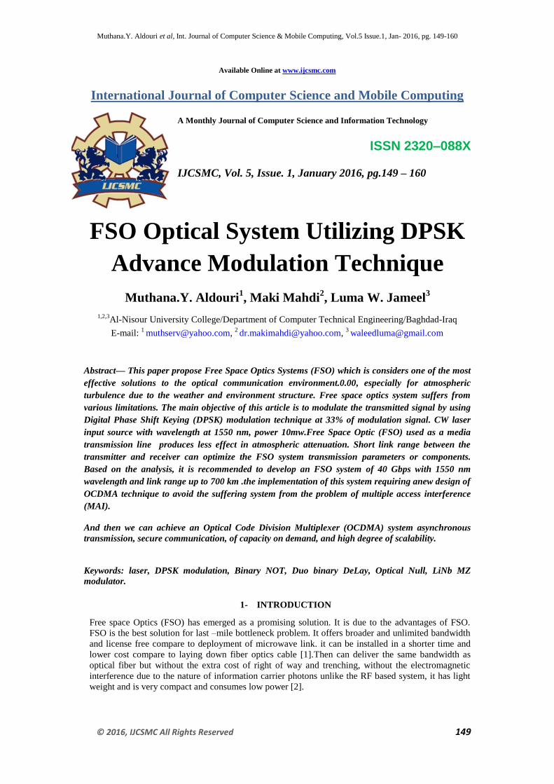
Figure(1). Below shows free space optical (FSO) transmission system. This diagram shows that free
space optical transmission systems loose some of their energy from signal scattering, absorption and
scintillation. Optical signal scattering occurs when light signals are redirected as they pass through
water particles. Optical signal absorption occurs as some optical energy is converted to heat as it
strikes particles (such as smog). Scintillation occurs when heated (such as from smokestacks) air
cause a bending of the optical beam. This example shows that it is possible to transmit multiple light
wave signals on different wavelengths (WDM) to increase the overall data transmission rate.
Fig.1: Free Space Optics-FSO Diagram
The SCM technique is attractive because it encompasses the multiplexing of both multichannel
of analog and/or digital signals. These signals can carry either voice, data, video, digital audio, high-
definition video or any other analog or digital information. In SCM system, the input signals are
modulated with different electrical carriers at microwave frequencies and then they are combined by
using a combiner. The combined signal is then modulated by intensity modulation or external
modulation techniques. The modulated light wave signal is transmitted through an optical fiber. At the
receiver end, the optical signal is converted back to an electrical current by a photodetector. The
particular signals can then be De multiplexed and demodulated, using conventional detection methods.
The attractive feature of SCM is the independence of the different channels. This allows for great
flexibility in the choice of modulation schemes. In addition to being flexible, the current SCM
technology is also cost-effective as it provides a way to take advantage of the multi-gigahertz
bandwidth of the fiber optics, using well-established microwave techniques for which components are
commercially available. Furthermore, it is less expensive than the corresponding WDM technology
[3].In this paper, a new and simple detection scheme named as AND subtraction is proposed. The
studies were made using EDW code of SAC-OCDMA system. The EDW code has a fixed weight of
three. The SCM is employed to improve the channel data rate of the OCDMA [4, 5]. A large number of
channels can be achieved with many code sequences and few subcarriers per code sequences, or with
the converse. It is shown in this paper that the hybrid of SCM SAC-OCDMA system using the
proposed AND subtraction detection technique provides a significantly better performance than the
hybrid system using complementary subtraction technique. The transmission distance of the hybrid
SCM SAC-OCDMA system can be extended using this new technique compared to the complementary
subtraction technique. The signal-to-noise ratio (SNR) is improved by 7dB when the transmitted power
is fixed at 0dBm.
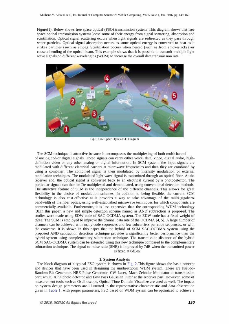
2. System Analysis The block diagram of a typical FSO system is shown in Fig. 2.This figure shows the basic concept
and devices that have been used in designing the unidirectional WDM system. There are Pseudo-
Random Bit Generator, NRZ Pulse Generator, CW Laser, Mach-Zehnder Modulator at transmission
part; while, APD photo detector and Low Pass Gaussian Filter at the receiver part. However, some of
measurement tools such as Oscilloscope, Optical Time Domain Visualize are used as well. The impact
on system design parameters are illustrated in the representative characteristic and data observation
given in Table 1; with proper parameters, FSO based on WDM system can be optimized to achieve a
Muthana.Y. Aldouri et al, Int. Journal of Computer Science & Mobile Computing, Vol.5 Issue.1, Jan- 2016, pg. 149-160
© 2016, IJCSMC All Rights Reserved 151
maximum link range of operation. The quality of the received signal is greatly depends on the
conditions of the free space channel and the WDM system design. In order to suppress the beam
diffraction that occurs naturally with propagation, an optical signal is then sent through an optical fiber
to a collimating optical system [7].
Fig.2: the system architecture of the OCDMA network.
Table 1
Representative characteristic and data observation
Characteristic Data Observation
Data rate 40 Gbps Data rate versus bit error ratio
Power 4mw Power versus bit error ratio
Link range 700 km Link range versus bit error ratio
No. of user Depend No. of user versus bit error ratio
Channel spacing 0.8 nm Channel spacing versus bit error ratio
2.1 OCDMA system
OCDMA system provide asynchronous transmission, secure communication, soft capacity on demand,
and high degree of scalability. This is the most advantages, but also OCDMA have more problems
representing that OCDMA system provide high degree of scalability and security .the optical CDMA
systems suffer from the problem of multiple access interference (MAI) as the number of users increase
the BER error rate degrade because the effect of MAI increase, so there is a limitation in number of
users, as the number of users increase SNR degrease and probability of error increase. There is a
limitation of speed also in optical CDMA system, since very short pulse are to be required within each
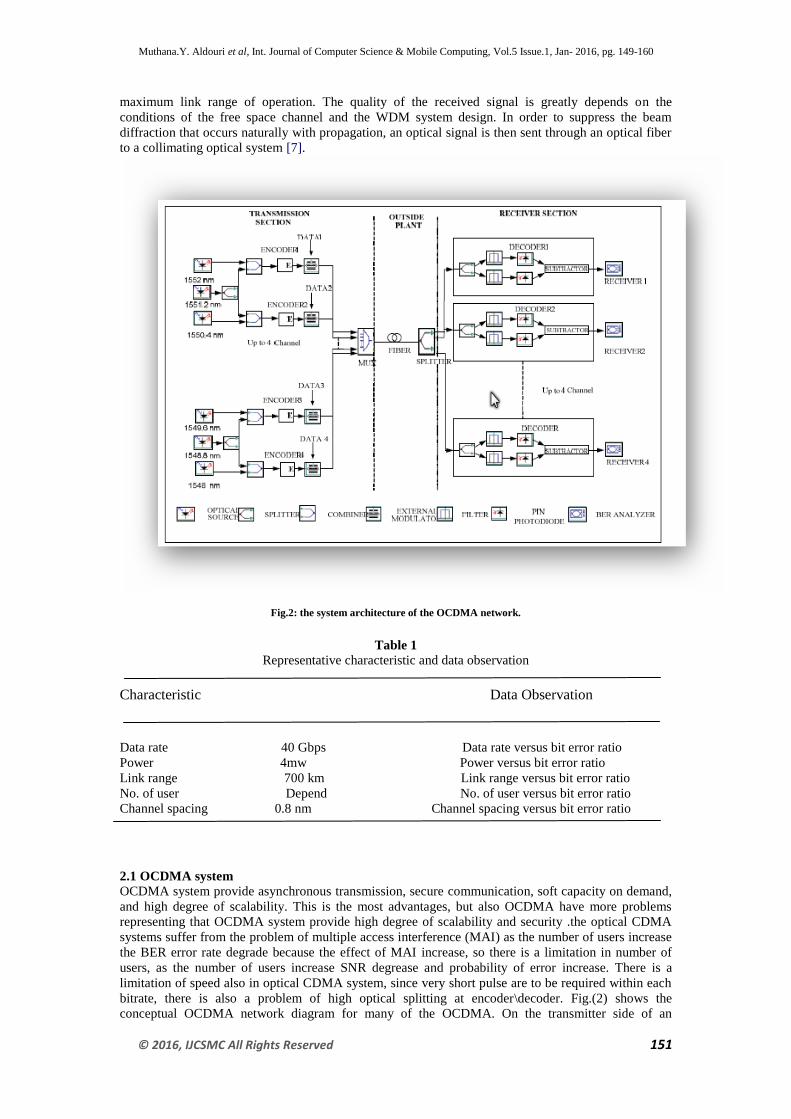
bitrate, there is also a problem of high optical splitting at encoder\decoder. Fig.(2) shows the
conceptual OCDMA network diagram for many of the OCDMA. On the transmitter side of an
Muthana.Y. Aldouri et al, Int. Journal of Computer Science & Mobile Computing, Vol.5 Issue.1, Jan- 2016, pg. 149-160
© 2016, IJCSMC All Rights Reserved 152
OCDMA system, an OCDMA encoder is used to encode the input data bit stream into an optical signal
depending on the mark sequence that is discrete for each user on the system. This encoded signal is
multiplexed with the signal generated from all other users. On the receiver an OCDMA decoder uses a
matched filter that corresponds to the signature sequence of the desired user. Depending on the
technology of choice, this decoder optical signal is then passed into a direct detection known as a
photo-detector (e.g., InGaAs PIN, Ge APD) or a differential detection balanced receiver, which
generates an electrical signal by Decoding on the channel code correctly situation the threshold for
tough choice, or by performing soft choice The purpose of an optical receiver is to convert modulated optical power to a binary data torrent. The composed of a PIN` photo detector diode, a trans impedance amplifier, an AGC post amplifier, a clock and data recovery, and a DE multiplexer circuit the function and operating characteristics of these circuits within the optical receiver
Fig.3 Conceptual diagram of an OCDMA network
2-2 Asynchronous DPSK Receivers:
Now let us treat the BPSK modulator and differential encoder jointly. Let us assume that the
elementary signal s0(t). From the respective waveform in Figure( 4). we see that the 180◦ phase shift
with respect to the current phase is triggered by the data symbol ai = 1, whereas there is no phase shift
if the data symbol ai = 0 appears on the modulator input. Such a modulation is called Differential
Phase Shift Keying (DPSK) and it can be achieved also through differential encoding and regular
BPSK modulation.

Muthana.Y. Aldouri et al, Int. Journal of Computer Science & Mobile Computing, Vol.5 Issue.1, Jan- 2016, pg. 149-160
© 2016, IJCSMC All Rights Reserved 153
Figure 4: Example of DPSK-modulated signal waveform
Instead of regular PSK modulation a DPSK modulation with asynchronous reception can be applied.
The signal is described by formula shown below, and the in-phase and quadrature baseband
components of signal (4) are determined by the expressions
Signals on the output of both receive filters are sampled once per modulation period and are
proportional to the cosine and sine of the angle φn + θ, respectively, where θ represents the carrier
phase difference between the received signal and the demodulating signal. For DPSK modulation for
which information is carried by the phase difference between the current and previous modulation
periods, besides a correlative receiver another type of asynchronous receiver is also possible. This
receiver is called an auto correlative receiver, because correlation is performed between the currently
received signal and the signal received during the previous modulation period and stored in the delay
line. Two versions of a DPSK auto correlative receiver are shown in Figure 5.
Figure 5- Auto correlative receiver for binary DPSK signals:
(a) suboptimal receiver; (b) optimal receiver with a matched filter
Muthana.Y. Aldouri et al, Int. Journal of Computer Science & Mobile Computing, Vol.5 Issue.1, Jan- 2016, pg. 149-160
© 2016, IJCSMC All Rights Reserved 154
Neglecting noise for a while, which is approximately equivalent to the assumption of a high signal-to-
noise ratio, we can describe the sample on the output of the correlator as a random variable U1:
The scheme is rather simple but its performance is inferior to the other receiver types, because in
reality the noise from the current and previous modulation periods disturbs the correlation process. for
high signal-to-noise ratio the error probability on the receiver output can be approximated by the
following formula shown below:
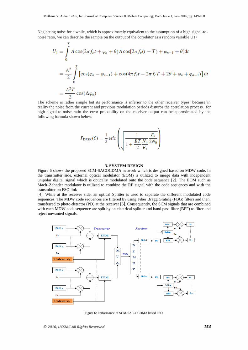
3. SYSTEM DESIGN Figure 6 shows the proposed SCM-SACOCDMA network which is designed based on MDW code. In
the transmitter side, external optical modulator (EOM) is utilized to merge data with independent
unipolar digital signal which is optically modulated onto the code sequence [2]. The EOM such as
Mach–Zehnder modulator is utilized to combine the RF signal with the code sequences and with the
transmitter on FSO link
[4]. While at the receiver side, an optical Splitter is used to separate the different modulated code
sequences. The MDW code sequences are filtered by using Fiber Bragg Grating (FBG) filters and then,
transferred to photo-detector (PD) at the receiver [5]. Consequently, the SCM signals that are combined
with each MDW code sequence are split by an electrical splitter and band pass filter (BPF) to filter and
reject unwanted signals.
Figure 6: Performance of SCM-SAC-OCDMA based FSO.
Muthana.Y. Aldouri et al, Int. Journal of Computer Science & Mobile Computing, Vol.5 Issue.1, Jan- 2016, pg. 149-160
© 2016, IJCSMC All Rights Reserved 155
3.1 Review of EDW CODE
EDW code is another version of DW code family [7]. The EDW code weights can a variable weight
that is greater than one. In this paper, the EDW with the weight of three is used as an example. As a
family of DW code, EDW can also be represented by using the KxN matrix. The essential EDW code
denoted by (6, 3, and 1) is shown below
Perceive that a similar structure of the basic DW code is still maintained with a minor modification,
whereby, the double weight pairs are maintained in a way to consent to
only two overlapping chips in every column. Thus, the 1, 2, 1 chips combination is maintained for
every three columns as in the basic DW code [8, 9]. This is important to maintain λ=1. The same
mapping technique as for DW code is used to augment the number of user. The example shows that we
can increase the number of users from three to six while the weight is still fixed at three. An MDW
code with weight of four denoted by (N, 3, 1) for any given code length N, which can be related to the
number of user K through.
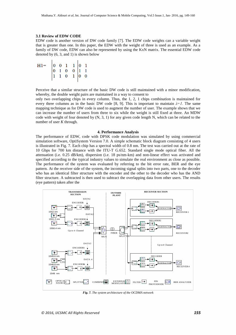
4. Performance Analysis
The performance of EDW, code with DPSK code modulation was simulated by using commercial
simulation software, OptiSystem Version 7.0. A simple schematic block diagram consisting of 4 users
is illustrated in Fig. 7. Each chip has a spectral width of 0.8 nm. The test was carried out at the rate of
10 Gbps for 700 km distance with the ITU-T G.652. Standard single mode optical fiber. All the
attenuation (i.e. 0.25 dB/km), dispersion (i.e. 18 ps/nm-km) and non-linear effect was activated and
specified according to the typical industry values to simulate the real environment as close as possible.
The performance of the system was evaluated by referring to the bit error rate, BER and the eye
pattern. At the receiver side of the system, the incoming signal splits into two parts, one to the decoder
who has an identical filter structure with the encoder and the other to the decoder who has the AND
filter structure. A subtracted is then used to subtract the overlapping data from other users. The results
(eye pattern) taken after the
E
E
ENCODER 1
ENCODER 2
DATA 1
DATA 2
MUX SPLITTER
FIBER
TRANSMISSION
SECTIONOUTSIDE
PLANT
RECEIVER SECTION
DATA 4
E
E
ENCODER 3
ENCODER 4
DATA 3
Up to 4 Channel
SUBTRACTOR
DECODER 1
RECEIVER 1
SUBTRACTOR
DECODER
RECEIVER 4
SUBTRACTOR
DECODER 2
RECEIVER 2
Up to 4 Channel
EXTERNAL MODULATOR
FILTERPIN
PHOTODIODEBER ANALYZERSPLITTER
OPTICALSOURCE COMBINER
1552 nm
1551.2 nm
1550.4 nm
1549.6 nm
1548.8 nm
1548 nm
Fig. 7. The system architecture of the OCDMA network
Muthana.Y. Aldouri et al, Int. Journal of Computer Science & Mobile Computing, Vol.5 Issue.1, Jan- 2016, pg. 149-160
© 2016, IJCSMC All Rights Reserved 156
Referring to figure 7. , we can see that in free space transmitter the data can transmit for more than 700
Km, at very stable system. The transmitter uses CW laser at the source specifications as follow
- with maximum signal power of 6 dBm
- wavelength at 1550 nm
- noise power equal to (-100 dBm)
- lower frequency limited = 1620.5nm
-upper frequency limited = 1498.96nm
To ensure the linearity of the system, the CW laser is properly biased and the peak –to-peak voltage of
the input signal cannot exceed the specified values. The data can transfer clearly as BER function that
equal to the value of 7.2 e-7
for maximum value while at the minimum length 100Km the value of BER
will be at 2.8 e-215
. Hence, we can say this is a good result for this system. For these results, the
following parameters were used: line width thermal noise= 3.75x10¹²
Hz; electrical bandwidth will be
equal to 80 MHz at the operating wavelength of 1550 nm. We can take the Erbium Doped Fiber
Amplifier (EDFA) with 20 dB gain, immediately after the transmitter to lunch power signals into fiber
to transmit the signal for long distance as possible which is depend to the type of amplifier and the
system design it mean the transmitter and receiver design . in this system we used the AND –
subtraction detection techniques in the receiver to demodulate the signal, also the complementary –
subtraction detection technique can be used in this system .for EDW code the more suitable technique
is AND-subtraction
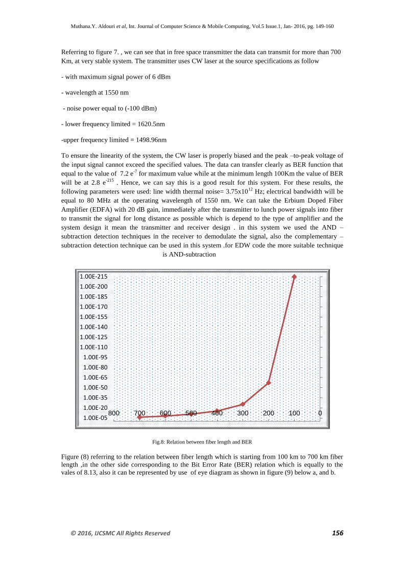
Fig.8: Relation between fiber length and BER
Figure (8) referring to the relation between fiber length which is starting from 100 km to 700 km fiber
length ,in the other side corresponding to the Bit Error Rate (BER) relation which is equally to the
vales of 8.13, also it can be represented by use of eye diagram as shown in figure (9) below a, and b.
1.00E-215
1.00E-200
1.00E-185
1.00E-170
1.00E-155
1.00E-140
1.00E-125
1.00E-110
1.00E-95
1.00E-80
1.00E-65
1.00E-50
1.00E-35
1.00E-20
1.00E-050100200300400500600700800
Muthana.Y. Aldouri et al, Int. Journal of Computer Science & Mobile Computing, Vol.5 Issue.1, Jan- 2016, pg. 149-160
© 2016, IJCSMC All Rights Reserved 157
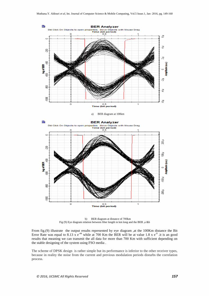
a) BER diagram at 100km
b) BER diagram at distance of 700km
Fig (9) Eye diagram relation between fiber length in km long and the BER ,a &b
From fig.(9) illustrate the output results represented by eye diagram ,at the 100Km distance the Bit
Error Rate was equal to 8.13 x e-44
while at 700 Km the BER will be at value 1.8 x e-9
.it is an good
results that meaning we can transmit the all data for more than 700 Km with sufficient depending on
the stable designing of the system using FSO media .
The scheme of DPSK design is rather simple but its performance is inferior to the other receiver types,
because in reality the noise from the current and previous modulation periods disturbs the correlation
process.
Muthana.Y. Aldouri et al, Int. Journal of Computer Science & Mobile Computing, Vol.5 Issue.1, Jan- 2016, pg. 149-160
© 2016, IJCSMC All Rights Reserved 158
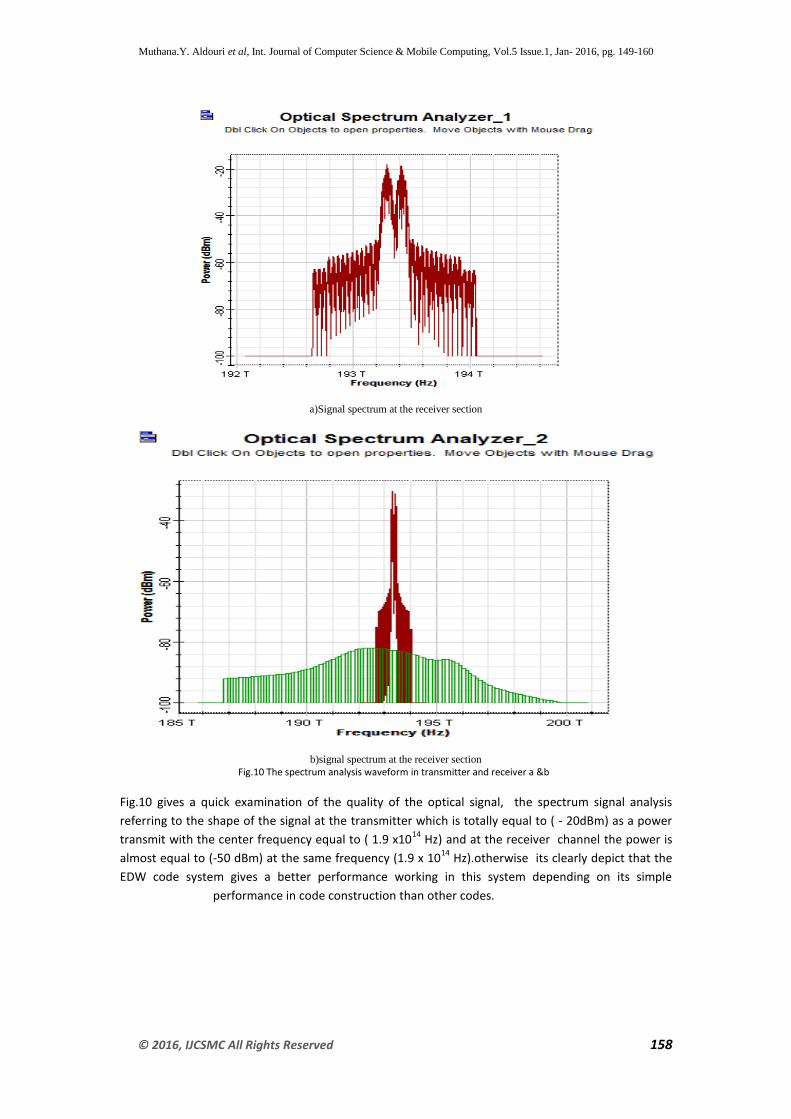
a)Signal spectrum at the receiver section
b)signal spectrum at the receiver section
Fig.10 The spectrum analysis waveform in transmitter and receiver a &b
Fig.10 gives a quick examination of the quality of the optical signal, the spectrum signal analysis
referring to the shape of the signal at the transmitter which is totally equal to ( - 20dBm) as a power
transmit with the center frequency equal to ( 1.9 x10¹⁴
Hz) and at the receiver channel the power is
almost equal to (-50 dBm) at the same frequency (1.9 x 10¹⁴
Hz).otherwise its clearly depict that the
EDW code system gives a better performance working in this system depending on its simple
performance in code construction than other codes.
Muthana.Y. Aldouri et al, Int. Journal of Computer Science & Mobile Computing, Vol.5 Issue.1, Jan- 2016, pg. 149-160
© 2016, IJCSMC All Rights Reserved 159
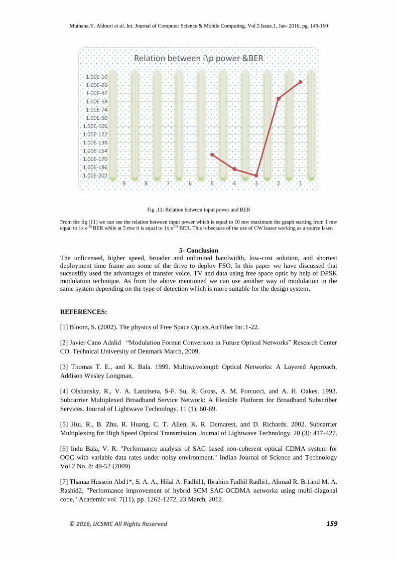
Fig .11: Relation between input power and BER
From the fig (11) we can see the relation between input power which is equal to 10 mw maximum the graph starting from 1 mw
equal to 1x e-25 BER while at 5 mw it is equal to 1x e158 BER. This is because of the use of CW leaser working as a source laser.
5- Conclusion
The unlicensed, higher speed, broader and unlimited bandwidth, low-cost solution, and shortest
deployment time frame are some of the drive to deploy FSO. In this paper we have discussed that
sucsusffly used the advantages of transfer voice, TV and data using free space optic by help of DPSK
modulation technique. As from the above mentioned we can use another way of modulation in the
same system depending on the type of detection which is more suitable for the design system.
REFERENCES:
[1] Bloom, S. (2002). The physics of Free Space Optics.AirFiber Inc.1-22.
[2] Javier Cano Adalid “Modulation Format Conversion in Future Optical Networks” Research Center
CO. Technical University of Denmark March, 2009.
[3] Thomas T. E., and K. Bala. 1999. Multiwavelength Optical Networks: A Layered Approach,
Addison Wesley Longman.
[4] Olshansky, R., V. A. Lanzisera, S-F. Su, R. Gross, A. M. Forcucci, and A. H. Oakes. 1993.
Subcarrier Multiplexed Broadband Service Network: A Flexible Platform for Broadband Subscriber
Services. Journal of Lightwave Technology. 11 (1): 60-69.
[5] Hui, R., B. Zhu, R. Huang, C. T. Allen, K. R. Demarest, and D. Richards. 2002. Subcarrier
Multiplexing for High Speed Optical Transmission. Journal of Lightwave Technology. 20 (3): 417-427.
[6] Indu Bala, V. R. "Performance analysis of SAC based non-coherent optical CDMA system for
OOC with variable data rates under noisy environment." Indian Journal of Science and Technology
Vol.2 No. 8: 49-52 (2009)
[7] Thanaa Hussein Abd1*, S. A. A., Hilal A. Fadhil1, Ibrahim Fadhil Radhi1, Ahmad R. B.1and M. A.
Rashid2, "Performance improvement of hybrid SCM SAC-OCDMA networks using multi-diagonal
code," Academic vol. 7(11), pp. 1262-1272, 23 March, 2012.
1.00E-202
1.00E-186
1.00E-170
1.00E-154
1.00E-138
1.00E-122
1.00E-106
1.00E-90
1.00E-74
1.00E-58
1.00E-42
1.00E-26
1.00E-10
123456789
Relation between i\p power &BER
Muthana.Y. Aldouri et al, Int. Journal of Computer Science & Mobile Computing, Vol.5 Issue.1, Jan- 2016, pg. 149-160
© 2016, IJCSMC All Rights Reserved 160
[8] M. Noshad and M. Brandt-Pearce, "Expurgated PPM using symmetric balanced incomplete block
designs," IEEE Communications Letters, vol. 16, pp. 968-971, 2012.
[9] T. H. Abd, et al., "Modeling and simulation of multi diagonal code with zero cross correlation for
SAC-OCDMA networks," 2011.
[10] Aljunid, S. A., M. Ismail, A. R. Ramli, B. M. Ali, and M. K.Abdullah.. A New Family of Optical
Code Sequences for Spectral Amplitude-Coding Optical CDMA Systems. IEEE Photonic Technology
Letters. 16(10) 2004
[11] Z. Zan, S. A. Aljunid, M. H. Yaacob, M. K. Abdullah &S.Shaari, Design Configuration of
Encoder And Decoder Modules for Modified Double Weight (MDW)Code Spectral Amplitudes
Coding (SAC) Optical Code Division Multiple Access (OCDMA) Based On Fiber Bragg Grating,
Second International Conference on Advanced Optoelectronics and Lasers, 12 September, 2005.
[12] Aljunid, S. A., M. Ismail, A. R. Ramli, B. M. Ali, and M. K. Abdullah.. A New Family of Optical
Code Sequences for Spectral Amplitude-Coding Optical CDMA Systems. IEEE Photonic Technology
Letters. 16(10) 2004
[13] D.S.Franco, K. Vaccaro, 2005. & Gant.Poly.Washim.”General, 2005).
[14] Krzysztof Wesołowski, INTRODUCTION TO DIGITAL COMMUNICATION SYSTEMS, John
Wiley and Sons, 2009.