
FSequence IPM Owners Guide.book
58
TM TM Freedom Sequence Intelligent Power Manager Owner’s Guide Freedom Sequence with six AC relays PN: 809-0912 shown. 809-0912 809-0913 PNs: FSequence IPM Owners Guide.book Page i Thursday, October 6, 2011 3:33 PM
Transcript of FSequence IPM Owners Guide.book

TM
TM
Freedom SequenceIntelligent Power Manager
Owner’s GuideFreedom Sequence with six AC relays PN: 809-0912 shown.
809-0912809-0913
PNs:
FSequence IPM Owners Guide.book Page i Thursday, October 6, 2011 3:33 PM

FSequence IPM Owners Guide.book Page ii Thursday, October 6, 2011 3:33 PM
975-0593-01-01 i
TrademarksXantrex and Smart choice for power are trademarks of Schneider Electric Services International sprl, registered in the United States and other countries. Other trademarks, registered trademarks, and product names are the property of their respective owners and are used herein for identification purposes only.
Notice of CopyrightFreedom Sequence Intelligent Power Manager Owner’s Guide © August 2011 Xantrex Technology USA Inc. All rights reserved. No part of this document may be reproduced in any form or disclosed to third parties without the express written consent of: Xantrex Technology USA Inc., 541 Roske Drive, Suite A, Elkhart, Indiana USA 46516. Xantrex Technology USA Inc. reserves the right to revise this document and to periodically make changes to the content hereof without obligation or organization of such revisions or changes unless required to do so by prior arrangement.
Exclusion for DocumentationUNLESS SPECIFICALLY AGREED TO IN WRITING, XANTREX TECHNOLOGY USA INC. (“XANTREX”)(A) MAKES NO WARRANTY AS TO THE ACCURACY, SUFFICIENCY OR SUITABILITY OF ANY TECHNICAL OR OTHER INFORMATION PROVIDED IN ITS MANUALS OR OTHER DOCUMENTATION;(B) ASSUMES NO RESPONSIBILITY OR LIABILITY FOR LOSSES, DAMAGES, COSTS OR EXPENSES, WHETHER SPECIAL, DIRECT, INDIRECT, CONSEQUENTIAL OR INCIDENTAL, WHICH MIGHT ARISE OUT OF THE USE OF SUCH INFORMATION. THE USE OF ANY SUCH INFORMATION WILL BE ENTIRELY AT THE USER’S RISK; AND
(C) REMINDS YOU THAT IF THIS MANUAL IS IN ANY LANGUAGE OTHER THAN ENGLISH, ALTHOUGH STEPS HAVE BEEN TAKEN TO MAINTAIN THE ACCURACY OF THE TRANSLATION, THE ACCURACY CANNOT BE GUARANTEED. APPROVED XANTREX CONTENT IS CONTAINED WITH THE ENGLISH LANGUAGE VERSION WHICH IS POSTED AT WWW.XANTREX.COM.
Date and RevisionAugust 2011 Rev B
To view, download, or print the latest revision, visit the website shown under Contact Information.
Document Part Number975-0593-01-01
Product Numbers809-0912 (Six AC relays)809-0913 (Four AC relays)
Contact InformationTelephone: 1 800 670 0707
Fax: 1 800 994 7828
Web: www.xantrex.com
FSequence IPM Owners Guide.book Page i Thursday, October 6, 2011 3:33 PM

ii Freedom Sequence Intelligent Power Manager Owner’s Guide
About This Guide
PurposeThe purpose of this Owner’s Guide is to provide explanations and procedures for operating the Freedom Sequence Intelligent Power Manager.
ScopeThe Guide provides safety and operating guidelines, as well as information on configuring the power manager.
It does not provide details about certain components that can be attached to the power manager. You need to consult the individual component’s owner’s guide for this information.
AudienceThe Guide is intended for users and operators of the Freedom Sequence Intelligent Power Manager. The Installation section, if present, is intended for qualified installers who need to install and configure any unit model of the Freedom Sequence Intelligent Power Manager. The installer should have knowledge and experience in installing electrical equipment, knowledge of the applicable installation codes, and awareness of the hazards involved in performing electrical work and how to reduce those hazards. A qualified technician or electrician has this knowledge and experience.
Conventions UsedThe following conventions are used in this guide.
STATEMENT OF HAZARDContains statements of avoidance or strict compliance.
Failure to follow these instructions will result in death or serious injury.
STATEMENT OF HAZARDContains statements of avoidance or strict compliance.
Failure to follow these instructions can result in death or serious injury.
STATEMENT OF HAZARDContains statements of avoidance or strict compliance.
Failure to follow these instructions can result in minor or moderate injury.
FSequence IPM Owners Guide.book Page ii Thursday, October 6, 2011 3:33 PM
975-0593-01-01 iii
Related InformationYou can find more information about Xantrex Technology USA Inc. as well as its products and services at www.xantrex.com.
STATEMENT OF HAZARDContains statements of avoidance or strict compliance.
Failure to follow these instructions can damage the unit and/or damage other equipment.
IMPORTANT: These notes describe things which are important for you to know, however, they are not as serious as a danger, warning, or caution.
The product marking on the left when found imprinted on electrical and electronic units and appliances means that you are to refer to this guide for cautions and warnings.
FSequence IPM Owners Guide.book Page iii Thursday, October 6, 2011 3:33 PM
iv Freedom Sequence Intelligent Power Manager Owner’s Guide
Important Safety Instructions
IMPORTANT: READ AND SAVE THIS OWNER’S GUIDE FOR FUTURE REFERENCE.
This chapter contains important safety instructions when operating the Freedom Sequence Intelligent Power Manager. Each time, before using the Freedom Sequence Intelligent Power Manager, READ ALL instructions and cautionary markings on or provided with the power manager and all appropriate sections of this guide.
NOTE: The Freedom Sequence Intelligent Power Manager contains no user-serviceable parts. For obtaining service, see “Warranty and Return Information” on page 41 for guidance.
NOTE: The Freedom Sequence Intelligent Power Manager must be provided with grounding conductors connected to the AC input/output connections.
NOTE: The power manager has no on/off switch. Circuits are always live when DC and AC input are present.
ELECTRICAL SHOCK HAZARD• Do not expose the power manager to rain, snow, spray, or bilge water.• Do not operate the power manager if it has received a sharp blow,
been dropped, has cracks or openings in the enclosure, or will not close, or otherwise damaged in any other way.
• Do not disassemble the power manager.• Disconnect both AC and DC power from the power manager before
attempting any maintenance or cleaning or working on any circuits connected to the power manager. See note below.
• Do not operate the power manager with damaged or substandard wiring. Make sure that all wiring is in good condition and is not undersized. Use copper conductors only.
Failure to follow these instructions will result in death or serious injury.
FSequence IPM Owners Guide.book Page iv Thursday, October 6, 2011 3:33 PM
975-0593-01-01 v
NOTE: Follow these instructions and those published by the battery manufacturer and the manufacturer of any equipment you intend to use in the vicinity of the battery. Review cautionary markings on these products and on the engine.
Precautions When Placing the Power Manager
NOTE: A controlled environment is an environment that is relatively free of solid airborne particulates, liquid, and/or gaseous elements. A controlled environment may also be provided by means of a totally closed, gasketed enclosure or the equivalent.
EXPLOSION HAZARDDo not work in the vicinity of lead-acid batteries. Batteries generate explosive gases during normal operation. See note below.
Failure to follow these instructions will result in death or serious injury.
PERSONAL INJURY HAZARDThis power manager is not intended for use by persons (including children) with reduced physical, sensory, or mental capabilities or lack of experience and knowledge, unless they have been given supervision or instruction concerning use of the appliance by a person responsible for their safety. Children should be supervised to ensure that they do not play with the power manager.
Failure to follow these instructions can result in death or serious injury.
EXPLOSION HAZARDDo not place the power manager in machinery space or in areas containing gasoline tanks or fittings in which ignition-protected equipment is required.
This equipment is intended for installation in accordance with the National Electrical Code, NFPA 70.
Failure to follow these instructions will result in death or serious injury.
ELECTRICAL SHOCK HAZARDTo reduce the risk of fire or electric shock, install in a controlled environment relatively free of contaminants.
Failure to follow these instructions can result in death or serious injury.
FSequence IPM Owners Guide.book Page v Thursday, October 6, 2011 3:33 PM

vi Freedom Sequence Intelligent Power Manager Owner’s Guide
FCC Information to the UserThis equipment has been tested and found to comply with the limits for a Class B digital device, pursuant to part 15 of the FCC Rules. These limits are designed to provide reasonable protection against harmful interference in a residential installation. This equipment generates, uses, and can radiate radio frequency energy and, if not installed and used in accordance with the instructions, may cause harmful interference to radio communications.
However, there is no guarantee that interference will not occur in a particular installation. If this equipment does cause harmful interference to radio or television reception, which can be determined by turning the equipment off and on, the user is encouraged to try to correct the interference by one or more of the following measures:
• Reorient or relocate the receiving antenna.• Increase the separation between the equipment and receiver.• Connect the equipment into an outlet on a circuit different from that to
which the receiver is connected.• Consult the dealer or an experienced radio/TV technician for help.
RISK OF DAMAGE TO THE POWER MANAGER• Never place the Freedom Sequence Intelligent Power Manager unit
directly above batteries; gases from a battery will corrode and damage the power manager.
• Do not place a battery on top of the power manager.
Failure to follow these instructions can damage the unit and/or damage other equipment.
Unauthorized changes or modifications to the equipment could void the user’s authority to operate the equipment.
FSequence IPM Owners Guide.book Page vi Thursday, October 6, 2011 3:33 PM
Important Safety Instructions . . . . . . . . . . . . . . . . . . . . . . . . . . . . . . . . . . . . . . . . . . . . . . . . . . . . . . . . . . . . . . . . . . . . . . . . . . . .iv
Introduction . . . . . . . . . . . . . . . . . . . . . . . . . . . . . . . . . . . . . . . . . . . . . . . . . . . . . . . . . . . . . . . . . . . . . . . . . . . . . . . . . . . . . . . . . 1
Mechanical Features. . . . . . . . . . . . . . . . . . . . . . . . . . . . . . . . . . . . . . . . . . . . . . . . . . . . . . . . . . . . . . . . . . . . . . . . . . . . . . . . . . . 5
Typical RV Wiring. . . . . . . . . . . . . . . . . . . . . . . . . . . . . . . . . . . . . . . . . . . . . . . . . . . . . . . . . . . . . . . . . . . . . . . . . . . . . . . . . . . . 6
Power Manager Configuration . . . . . . . . . . . . . . . . . . . . . . . . . . . . . . . . . . . . . . . . . . . . . . . . . . . . . . . . . . . . . . . . . . . . . . . . . . . 7
Circuit Status . . . . . . . . . . . . . . . . . . . . . . . . . . . . . . . . . . . . . . . . . . . . . . . . . . . . . . . . . . . . . . . . . . . . . . . . . . . . . . . . . . . . . . . . 9
Basic Configuration Settings . . . . . . . . . . . . . . . . . . . . . . . . . . . . . . . . . . . . . . . . . . . . . . . . . . . . . . . . . . . . . . . . . . . . . . . . . . . 11
Advanced Settings . . . . . . . . . . . . . . . . . . . . . . . . . . . . . . . . . . . . . . . . . . . . . . . . . . . . . . . . . . . . . . . . . . . . . . . . . . . . . . . . . . . 20
Circuit Level Advanced Settings . . . . . . . . . . . . . . . . . . . . . . . . . . . . . . . . . . . . . . . . . . . . . . . . . . . . . . . . . . . . . . . . . . . . . . . . 27
Freedom Sequence Operational Concepts . . . . . . . . . . . . . . . . . . . . . . . . . . . . . . . . . . . . . . . . . . . . . . . . . . . . . . . . . . . . . . . . . 33
Freedom Sequence SCP Menu Map. . . . . . . . . . . . . . . . . . . . . . . . . . . . . . . . . . . . . . . . . . . . . . . . . . . . . . . . . . . . . . . . . . . . . . 40
Specifications . . . . . . . . . . . . . . . . . . . . . . . . . . . . . . . . . . . . . . . . . . . . . . . . . . . . . . . . . . . . . . . . . . . . . . . . . . . . . . . . . . . . . . . 41
Warranty and Return Information . . . . . . . . . . . . . . . . . . . . . . . . . . . . . . . . . . . . . . . . . . . . . . . . . . . . . . . . . . . . . . . . . . . . . . . 42
Contents
FSequence IPM Owners Guide.book Page i Thursday, October 6, 2011 3:33 PM

FSequence IPM Owners Guide.book Page ii Thursday, October 6, 2011 3:33 PM
975-0593-01-01 1
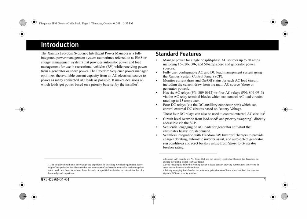
IntroductionThe Xantrex Freedom Sequence Intelligent Power Manager is a fully integrated power management system (sometimes referred to as EMS or energy management system) that provides automatic power and load management for use in recreational vehicles (RV) while receiving power from a generator or shore power. The Freedom Sequence power manager optimizes the available current capacity from an AC electrical source to power as many connected AC loads as possible. It makes decisions on which loads get power based on a priority base set by the installer1.
Standard Features• Manage power for single or split-phase AC sources up to 50 amps
including 15-, 20-, 30-, and 50-amp shore and generator power sources.
• Fully user configurable AC and DC load management system using the Xanbus System Control Panel (SCP).
• Monitor current draw and On/Off status for each AC load circuit, including the current draw from the main AC source (shore or generator power).
• Has six AC relays (PN: 809-0912) or four AC relays (PN: 809-0913) via the AC relay terminal blocks which can control AC load circuits rated up to 15 amps each.
• Four DC relays (via the DC auxiliary connector port) which can control external DC circuits based on Battery Voltage. These four DC relays can also be used to control external AC circuits2.
• Circuit level override from load-shed3 and priority swapping4, directly accessible via the SCP.
• Sequential engaging of AC loads for generator soft-start that eliminates heavy inrush demand.
• Seamless integration with Freedom SW Inverter/Chargers to provide charger derating, automatic inverter assist, and auto-detect generator run conditions and reset breaker rating from Shore to Generator breaker rating.
1.The installer should have knowledge and experience in installing electrical equipment, knowl-edge of the applicable installation codes, and awareness of the hazards involved in performing elec-trical work and how to reduce those hazards. A qualified technician or electrician has thisknowledge and experience.
2.External AC circuits are AC loads that are not directly controlled through the Freedom Se-quence’s available six (or four) AC relays.3.Load shedding is defined as cutting power to loads that are drawing current from the system inorder to avoid an overload condition. 4.Priority swapping is defined as the automatic prioritization of loads when one load has been as-signed a different priority number.
FSequence IPM Owners Guide.book Page 1 Thursday, October 6, 2011 3:33 PM

2 Freedom Sequence Intelligent Power Manager Owner’s Guide
Introduction
Material ListThe Freedom Sequence ships with the following items:
• one Freedom Sequence unit,• owner’s and installation guides,• DC auxiliary connector wiring harness,• AC wiring terminal covers, and• Xanbus terminator.
NOTE: Keep the carton and packing material in case you need to return the power manager for servicing.
Xanbus terminator
DC auxiliary connector wiring harness
Freedom Sequence unit
AC wiring terminal covers
Owner’s and Installation guides
PN: 809-0912 shown
FSequence IPM Owners Guide.book Page 2 Thursday, October 6, 2011 3:33 PM

975-0593-01-01 3
Introduction
Compatible Products and Accessories1
The Xanbus System Control Panel (SCP) enables you to monitor and control all the power components of the Freedom Sequence power manager from a single easy-to-use interface.
The Xanbus Automatic Generator Start (AGS) is a panel and a control module system that provides automatic activation for your generator. If the AGS is present in the Xanbus network, the power manager does not need the B+ signal to be hardwired to the generator for it to receive generator-run conditions.
Together with the Freedom SW Series Inverter/Charger, the power manager provides advanced power optimization features of interactive charger de-rating and automatic inverter assist to provide additional power to support high peak power demands.
1.For an updated list, visit www.xantrex.com.
Product/Accessory Product NumberFreedom SW Series Inverter/Charger (12 and 24-volt systems)
815-2012, 815-2024 (2kW)815-3012, 815-3024 (3kW)
Xanbus System Control Panel (SCP) 809-0921
Xanbus Automatic Generator Start (AGS) 809-0915
25-ft network cable for SCP 809-0940
75-ft network cable for SCP 809-0942
FREEDOM SW 3012
FREEDOM SW 3012
Inverter
Reset
Enable
Inverter
AC/
On
Charge Fault
Freedom inverter/charger
SCP
AGS
25-ft cable 75-ft cable
FSequence IPM Owners Guide.book Page 3 Thursday, October 6, 2011 3:33 PM
4 Freedom Sequence Intelligent Power Manager Owner’s Guide
Introduction
Xanbus System
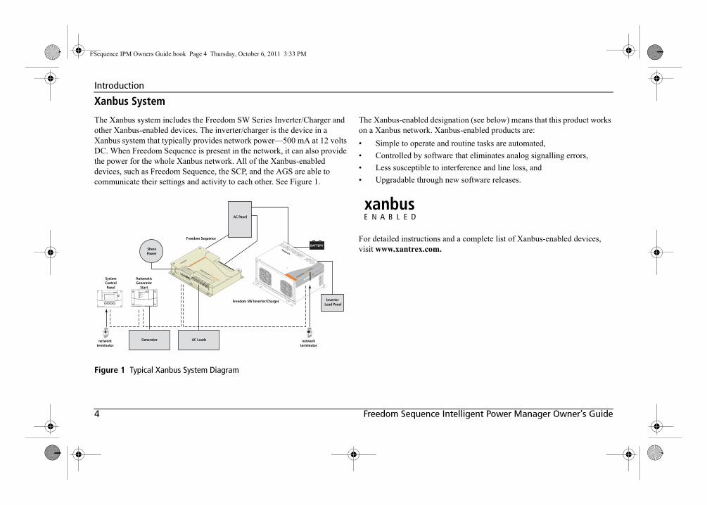
The Xanbus system includes the Freedom SW Series Inverter/Charger and other Xanbus-enabled devices. The inverter/charger is the device in a Xanbus system that typically provides network power—500 mA at 12 volts DC. When Freedom Sequence is present in the network, it can also provide the power for the whole Xanbus network. All of the Xanbus-enabled devices, such as Freedom Sequence, the SCP, and the AGS are able to communicate their settings and activity to each other. See Figure 1.
The Xanbus-enabled designation (see below) means that this product works on a Xanbus network. Xanbus-enabled products are:
• Simple to operate and routine tasks are automated,
• Controlled by software that eliminates analog signalling errors,
• Less susceptible to interference and line loss, and
• Upgradable through new software releases.
For detailed instructions and a complete list of Xanbus-enabled devices, visit www.xantrex.com.
Figure 1 Typical Xanbus System Diagram
Xanbus System Control Panel
Xanbus Automatic Generator Start
SystemControlPanel
networkterminator
networkterminator
AutomaticGenerator
Start
Freedom Sequence
Freedom SW Inverter/Charger
FREEDOM SW 3012
FREEDOM SW 3012
Inverter
Reset
Enable
Inverter
AC/
On
Charge Fault
Generator
ShorePower
AC Loads
AC Panel
BATTERY
Inverter Load Panel
FSequence IPM Owners Guide.book Page 4 Thursday, October 6, 2011 3:33 PM

975-0593-01-01 5
Mechanical FeaturesThis section describes the different parts of the Freedom Sequence.
Ports and Terminals
Figure 2 Freedom Sequence Ports and Terminals
13
5
4
6
2
Item Description1 AC Main section contains the current and voltage sensors to
monitor the AC source and provides the pass-through wiring from a transfer switch to the vehicle’s main distribution panel.
2 AC Main panel cover (removable for easy access)
3 Xanbus interface ports are used to connect Xanbus-enabled devices including the SCP, AGS and Freedom SW.
4 DC auxiliary connector port contains the terminals for four DC relays, B+ signal and DC power to the Freedom Sequence.
5 AC relay three-wire terminal blocks provide six (or four) Cage Clamp® connectors for connecting AC load circuits. One load circuit corresponds to one AC relay. The relays are bidirectional meaning, there are no designated AC IN and AC OUT terminals.
6 Mounting holes are used for mounting the Freedom Sequence unit. There are six holes provided on the unit.
ELECTRICAL SHOCK HAZARDDisconnect all DC and AC power before opening the AC Main panel.
Failure to follow these instructions will result in death or serious injury.
FSequence IPM Owners Guide.book Page 5 Thursday, October 6, 2011 3:33 PM

6 Freedom Sequence Intelligent Power Manager Owner’s Guide
Typical RV Wiring
Figure 3 Typical RV Wiring Diagram With Freedom Sequence
INVERTERSUBPANEL
GENERATOR30A
FREEDOM SW 3012
FREEDOM SW 3012
Inverter
Reset
Enable
Inverter
AC/
On
Charge Fault
Inverter/Charger
TO SHORECONNECTION
MAIN ACPANEL
START HOUSE
ALTERNATOR
ISOLATOR
12V FUSEPANEL
B+ SIGNAL
DC RELAYS
AC 6AC 5
AC 4AC 3
AC 2AC 1
DC RELAY 1
DC RELAY 2
BATT
DC AUXHARNESS
AGS
TM
SCP
TM
50A
BATTERY
DC LINE
AC LINE AC DISCONNECT
XANBUS DC DISCONNECT
50A
300A
300A
A
A
NOTE: The Freedom Sequence power manager must be permanently installed by a qualified installer in a controlled environment. Figure 3 shows a simple configuration where thepower manager is installed with a power supply line(either shore or generator), one Freedom SW inverter/charger, a Xanbus SCP, a Xanbus AGS, and variouselectrical appliances in a typical RV. Means of over-current protection and disconnection must be incor-porated into the fixed wiring, in accordance with theelectrical code that governs each installation.
IMPORTANT: This illustration is not a detailed technical wiring schematic.
FSequence IPM Owners Guide.book Page 6 Thursday, October 6, 2011 3:33 PM
975-0593-01-01 7
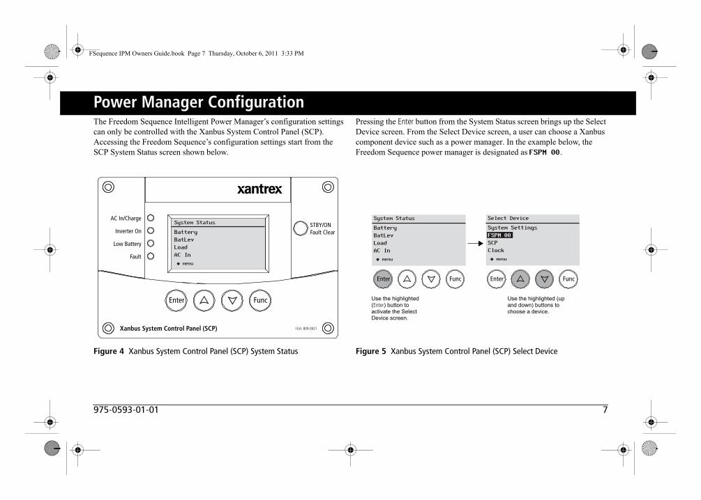
Power Manager ConfigurationThe Freedom Sequence Intelligent Power Manager’s configuration settings can only be controlled with the Xanbus System Control Panel (SCP). Accessing the Freedom Sequence’s configuration settings start from the SCP System Status screen shown below.
Pressing the Enter button from the System Status screen brings up the Select Device screen. From the Select Device screen, a user can choose a Xanbus component device such as a power manager. In the example below, the Freedom Sequence power manager is designated as FSPM 00.
Figure 4 Xanbus System Control Panel (SCP) System Status
Xanbus System Control Panel (SCP) FGA: 809-0921
AC In/Charge
Inverter On
Low Battery
Fault
STBY/ONFault Clear
TM
Enter Func
System Status
BatteryBatLevLoadAC In
menu
Figure 5 Xanbus System Control Panel (SCP) Select Device
System Status
BatteryBatLevLoadAC In
menu
Enter Func Enter Func
Select Device
System SettingsFSPM 00SCPClock
menu
Use the highlighted (Enter) button to activate the Select Device screen.
Use the highlighted (up and down) buttons to choose a device.
FSequence IPM Owners Guide.book Page 7 Thursday, October 6, 2011 3:33 PM

8 Freedom Sequence Intelligent Power Manager Owner’s Guide
Power Manager Configuration
Figure 6 Freedom Sequence Device Status Screen
System Status
BatteryBatLevLoadAC In
menu
FSPM 00: Status
AC Src TypeAC SourceL1 AmpsL2 Amps
1-PhAuto0.0A0.0A
FSPM 00: Status
AC Src TypeAC SourceL1 AmpsL2 AmpsBatt VoltageCircuit StatusConfigAdvanced Settings
1-PhAuto0.0A0.0A12.0V
Enter Func Enter Func Enter Func
Select Device
System SettingsFSPM 00SCPClock
menu
Complete list of device-specific status information including basic configuration and advanced settings for the Freedom Sequence.
To view the Freedom Sequence’s Device Status, press the Enter button from the Select Device screen.
From this Device Status screen, use the highlighted (up and down) buttons to view various status information such as the AC source type, line current, and battery level. See the complete list on the right.
From this Device Status screen, basic configuration and advanced settings can also be accessed.
The Advanced Settings are available for installers.
FSequence IPM Owners Guide.book Page 8 Thursday, October 6, 2011 3:33 PM

975-0593-01-01 9
Circuit Status
Figure 7 Freedom Sequence Circuit Status Screen
FSPM 00: Circuit Status
1 ACLoad11 Last Shed Current2 ACLoad22 Last Shed Current
On 3.0A6.0A
On 4.5A4.0A
Enter Func Enter Func
FSPM 00: Status
L1 AmpsL2 AmpsBatt VoltageCircuit Status
20.0A18.5A12.0V
FSPM 00: Circuit Status
1 ACLoad11 Last Shed Current2 ACLoad22 Last Shed Current3 ACLoad33 Last Shed Current4 ACLoad44 Last She Current5 ACLoad55 Last Shed CurrentCont
On 3.0A6.0A
On 4.5A4.0A
On 2.5A2.5A
On 2.3A2.0A
On 3.7A1.0A
FSPM 00: Circuit Status
6 ACLoad66 Last Shed Current7 DCLoad17 Last Shed Current8 DCLoad28 Last Shed Current9 DCLoad39 Last She Current10 DCLoad410 Last Shed Current
On 3.0A4.0A
On N/AN/A
On N/AN/A
On N/AN/A
On N/AN/A
Enter Func
FSPM 00: Circuit Status
4 Last She Current5 ACLoad55 Last Shed CurrentCont
2.0AOn 3.7A
1.0A
First five Circuit Status items.
From the device Status screen, scroll down (1) until Circuit Status is highlighted then, press Enter (2) to bring up the circuit status screen.
12 3 4
Last five Circuit Status items.
NOTE: This example shows screens for a Freedom Sequence six-circuit model PN: 809-0912.
Display each item using the Up and Down buttons (3). The statuses of the first five circuits are displayed.
5To display the statuses of the next set of circuits, scroll down (4) until Cont is highlighted then, press Enter (5) to bring up the second circuit status screen.
NOTE: Use the Func button to exit out of each screen.
FSequence IPM Owners Guide.book Page 9 Thursday, October 6, 2011 3:33 PM
10 Freedom Sequence Intelligent Power Manager Owner’s Guide
Circuit Status
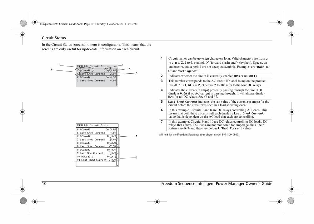
In the Circuit Status screens, no item is configurable. This means that the screens are only useful for up-to-date information on each circuit.
FSPM 00: Circuit Status
1 ACLoad11 Last Shed Current2 ACLoad22 Last Shed Current
On 3.0A2.0A
On 4.5A4.0A
FSPM 00: Circuit Status
6 ACLoad66 Last Shed Current7 DCLoad77 Last Shed Current8 DCLoad88 Last Shed Current9 DCLoad99 Last She Current10 DCLoad1010 Last Shed Current
On 3.0A4.0A
On N/A5.0A
On N/A7.5A
On N/AN/A
On N/AN/A
1
3
2
4
5
6
7
1 Circuit names can be up to ten characters long. Valid characters are from a to z, A to Z, 0 to 9, symbols '/' (forward slash) and '-'(hyphen). Spaces, an underscore, and a period are not accepted symbols. Examples are “Main-A/C” and “Refrigerat”.
2 Indicates whether the circuit is currently enabled (ON) or not (Off).
3 This number corresponds to the AC circuit ID label found on the product, like AC 1 is 1, AC 2 is 2, et cetera. 7 to 10a refer to the four DC relays.
a.5 to 8 for the Freedom Sequence four-circuit model PN: 809-0913.
4 Indicates the current (in amps) presently passing through the circuit. It displays 0.0A if no AC current is passing through. It will always displayN/A for all DC relays. See #6 and #7.
5 Last Shed Current indicates the last value of the current (in amps) for the circuit before the circuit was shed in a load shedding event.
6 In this example, Circuits 7 and 8 are DC relays controlling AC loads. This means that both these circuits will each display a Last Shed Current value that is dependent on the AC load that each are controlling.
7 In this example, Circuits 9 and 10 are DC relays controlling DC loads. DC relays that control DC loads are not monitored for amperage, thus, their statuses are N/A and there are no Last Shed Current values.
FSequence IPM Owners Guide.book Page 10 Thursday, October 6, 2011 3:33 PM

975-0593-01-01 11
Basic Configuration Settings
List of configurable settings includes:1. Mode – can be set to Operating or Standby.2. SHR BKR Mode – shore breaker mode can be set to Auto or Manual.3. SHR BKR Rating – shore breaker rating sets the breaker amperage.
4. Circuit Config – brings up the Circuit Config screen. See next page.
5. Restore Defaults loads back the OEM settings for all basic configuration and advanced settings.
Figure 8 Freedom Sequence Basic Configuration Screen
Enter Func Enter Func
FSPM 00: Status
L2 AmpsBatt VoltageCircuit StatusConfig
On 0.0A12.8V
FSPM 00: Config
ModeSHR BKR ModeSHR BKR RatingCircuit Config
[Operating][Auto][30.0A]
FSPM 00: Config
ModeSHR BKR ModeSHR BKR RatingCircuit ConfigRestore Defaults
[Operating][Auto][30.0A]
Complete list of circuit configuration items.
To activate a specific configuration setting, move through each item using the Up and Down buttons (3). When a selection is made, press the Enter button (4) to activate the highlighted configuration setting.
From the Device Status screen, scroll down (1) until Config is highlighted then, press Enter (2) to bring up the basic Configuration screen.
12 34
NOTE: Use the Func button to exit out of each screen.
FSequence IPM Owners Guide.book Page 11 Thursday, October 6, 2011 3:33 PM

12 Freedom Sequence Intelligent Power Manager Owner’s Guide
Basic Configuration Settings
List of circuit configurable settings includes:
1. Priority – a numerical circuit priority designation from 1 to 101. Each circuit will have a unique designation.
2. Load Shed – can be set to Disabled or Enabled
Figure 9 Freedom Sequence Circuit Configuration Screen
Enter Func Enter Func
FSPM 00: Status
L2 AmpsBatt VoltageCircuit StatusConfig
On 0.0A12.8V
FSPM 00: Config
ModeSHR BKR ModeSHR BKR RatingCircuit Config
[Operating][Auto][30.0A]
Enter Func
FSPM 00: Circuit Config
1 ACLoad11 Priority1 Load Shed2 ACLoad2
[1][Enabled]
FSPM 00: Circuit Config
1 ACLoad11 Priority1 Load Shed2 ACLoad22 Priority2 Load Shed3 ACLoad33 Priority3 Load Shed4 ACLoad44 Priority4 Load Shed5 ACLoad55 Priority5 Load ShedCont
[1][Enabled]
[2][Enabled]
[3][Enabled]
[4][Enabled]
[5][Enabled]
FSPM 00: Circuit Config
6 ACLoad66 Priority6 Load Shed7 DCLoad17 Priority7 Load Shed8 DCLoad28 Priority8 Load Shed9 DCLoad39 Priority9 Load Shed10 DCLoad410 Priority10 Load Shed
[6][Enabled]
[7][Enabled]
[8][Enabled]
[9][Enabled]
[10][Enabled]
Enter Func
FSPM 00: Config
ModeSHR BKR ModeSHR BKR RatingCircuit Config
[Operating][Auto][30.0A]
Complete list of circuit configuration items.
To activate a specific configuration setting, move through each item using the Up and Down buttons (3). When a selection is made, press the Enter button (4) to activate the highlighted configuration setting. To activate the circuit configuration screen, scroll down (5) until Circuit Config is highlighted then, press Enter (6) to bring up the screen. To activate a specific circuit configuration setting, move through each item using the Up and Down buttons (7). When a selection is made, press the Enter button (8) to activate the highlighted circuit configuration setting.
From the Device Status screen, scroll down (1) until Config is highlighted then, press Enter (2) to bring up the basic Configuration screen.
12 34 56
78
To display the next set of circuit configurations, scroll down until Cont is highlighted then, press Enter to bring up the second screen.
NOTE: Use the Func button to exit out of each screen.
1.1 to 8 for the Freedom Sequence four-circuit model PN: 809-0913.
FSequence IPM Owners Guide.book Page 12 Thursday, October 6, 2011 3:33 PM

975-0593-01-01 13
Basic Configuration Settings
Mode
The Freedom Sequence operates in two modes: Operating or Standby.
When set to Operating mode, Freedom Sequence performs the normal function of controlling the AC and DC loads on the system. In this mode, all the status information of the Freedom Sequence can be accessed via the Xanbus System Control Panel (SCP) and a limited number of configuration settings can be changed as shown in “Freedom Sequence Basic Configuration Screen” on page 11.
Freedom Sequence can be set to Standby mode to stop it from controlling the AC and DC loads on the system. When this mode is selected, Freedom Sequence allows accessibility to change all the configuration on the Freedom Sequence, including restoring to OEM default settings1.
When Freedom Sequence is first powered up, it will start operation in Operating mode.
To change the Mode from the Device Status screen:
1.OEM default settings (the “OEM Profile”) are programmed by the Original Equipment Manufac-turer. The OEM profile is available and can be accessed and modified via the XDT only.
FSPM 00: Status
L2 AmpsBatt VoltageCircuit StatusConfig
On 0.0A12.8V
FSPM 00: Config
ModeSHR BKR ModeSHR BKR RatingCircuit Config
[Operating][Auto]
[30.0A]
FSPM 00: Config
ModeSHR BKR ModeSHR BKR RatingCircuit Config
[Standby][Auto][30.0A]
FSPM 00: Config
ModeSHR BKR ModeSHR BKR RatingCircuit Config
[*Operating][Auto][30.0A]
FSPM 00: Config
ModeSHR BKR ModeSHR BKR RatingCircuit Config
[Standby][Auto][30.0A]
1 Press down until the field is selected.
3 Press to change the setting.
4 Press to select a new value.
5 Press to confirm the new value.
2 Press to select Config.
FSequence IPM Owners Guide.book Page 13 Thursday, October 6, 2011 3:33 PM
14 Freedom Sequence Intelligent Power Manager Owner’s Guide
Basic Configuration Settings
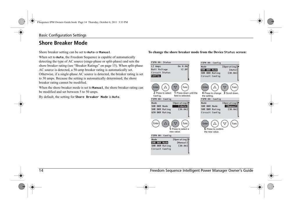
Shore Breaker Mode
Shore breaker setting can be set to Auto or Manual.
When set to Auto, the Freedom Sequence is capable of automatically detecting the type of AC source (singe-phase or split-phase) and sets the shore breaker rating (see “Breaker Ratings” on page 15). When split-phase AC source is detected, a 50-amp breaker rating is automatically set. Otherwise, if a single-phase AC source is detected, the breaker rating is set to 30 amps. Because the setting is automatically determined, the shore breaker rating cannot be modified.
When the shore breaker mode is set to Manual, the shore breaker rating can be modified and set between 5 to 50 amps.
By default, the setting for Shore Breaker Mode is Auto.
To change the shore breaker mode from the Device Status screen:
FSPM 00: Status
L2 AmpsBatt VoltageCircuit StatusConfig
On 0.0A12.8V
FSPM 00: Config
ModeSHR BKR ModeSHR BKR RatingCircuit Config
[Operating][Auto]
[30.0A]
FSPM 00: Config
ModeSHR BKR ModeSHR BKR RatingCircuit Config
[Operating][Manual][30.0A]
FSPM 00: Config
ModeSHR BKR ModeSHR BKR RatingGEN BKR Rating
[Operating][*Auto][30.0A]
FSPM 00: Config
ModeSHR BKR ModeSHR BKR RatingCircuit Config
[Operating][Manual][30.0A]
1 Press down until the field is selected.
3 Scroll down.
5 Press to select a new value.
6 Press to confirm the new value.
2 Press to select Config.
4 Press to change the setting.
FSequence IPM Owners Guide.book Page 14 Thursday, October 6, 2011 3:33 PM

975-0593-01-01 15
Basic Configuration Settings
Breaker RatingsThe breaker rating sets the current limit which is used by Freedom Sequence to restrict the consumption of power within the system by all AC load circuits. Freedom Sequence stores in its memory different settings for the Shore Breaker and the Generator Breaker. The Freedom Sequence applies the shore or generator breaker rating based on the source of AC Input. See “Auto-Detection of AC Input Source (Shore/Gen)” on page 33 for more information.
Freedom Sequence can automatically detect if the AC input source passing through it is a split-phase or single-phase. The current limits are applied on Line1 and Line2 circuits accordingly. For example, if the AC input source is a 30-amp split-phase AC line, Freedom Sequence will apply a current limit of 30 amps for each circuit. Line1 will have a 30-amp limit and Line2 as well. If it detects a single-phase AC line and the shore breaker rating is set to 30 amps, Freedom Sequence will apply a combined 30-amp limit to loads connected with Line1and Line2.
Shore Breaker Rating
Value can only be changed when the shore breaker mode is set to Manual. Values range from 5 to 50 amps.
To change the shore breaker rating from the Device Status screen:
FSPM 00: Status
L2 AmpsBatt VoltageCircuit StatusConfig
On 0.0A12.8V
FSPM 00: Config
ModeSHR BKR ModeSHR BKR RatingCircuit Config
[Operating][Manual][30.0A]
FSPM 00: Config
ModeSHR BKR ModeSHR BKR RatingCircuit Config
[Operating][Manual][25.0A]
FSPM 00: Config
ModeSHR BKR ModeSHR BKR RatingCircuit Config
[Operating][Manual][*30.0A]
FSPM 00: Config
ModeSHR BKR ModeSHR BKR RatingCircuit Config
[Operating][Manual][25.0A]
1 Press down until the field is selected.
3 Scroll down.
5 Press to select a new value.
6 Press to confirm the new value.
2 Press to select Config.
4 Press to change the setting.
FSequence IPM Owners Guide.book Page 15 Thursday, October 6, 2011 3:33 PM

16 Freedom Sequence Intelligent Power Manager Owner’s Guide
Basic Configuration Settings
Restore DefaultsFreedom Sequence stores different profiles in its memory: Factory, OEM, and User. Each profile can store an entirely different configuration for Freedom Sequence and its AC/DC Relays.
By default, the OEM and User profiles have settings that are the same as the Factory profile.
Upon start-up of Freedom Sequence, the User profile is used as the active profile to perform the AC and DC load-shedding functions. If settings are changed on the active profile, they automatically get copied to the User profile. If by mistake, a wrong setting is configured, all basic and advanced settings can be restored to their OEM settings via Restore Defaults from the Config screen on the SCP. The OEM profile can only be accessed and modified via the XDT tool.
To restore to OEM defaults, the Mode must be first changed to Standby. See “Mode” on page 13.
To Restore Defaults from the Device Status screen:
FSPM 00: Status
L2 AmpsBatt VoltageCircuit StatusConfig
On 0.0A12.8V
FSPM 00: Config
SHR BKR ModeSHR BKR RatingCircuit ConfigRestore Defaults
[Manual][30.0A]
3 Press to scroll down.
4 Press to restore default settings.
1 Press to scroll down.
2 Press to select Config.
FSequence IPM Owners Guide.book Page 16 Thursday, October 6, 2011 3:33 PM

975-0593-01-01 17
Basic Configuration Settings
Circuit ConfigurationThe circuit configuration screen displays five circuits at a time (see “Freedom Sequence Basic Configuration Screen” on page 11).
Each circuit has settings that can be configured individually.
• Priority – a numerical circuit priority designation from 1 to 101. This setting will allow a circuit to be re-prioritized. 1 is highest priority and 10 is the lowest priority.
• Load Shed – can be set to Disabled or Enabled.This setting will allow a circuit to be subjected to load shedding or not.
Circuit Priority
Each AC relay of the power manager that is configured to control an AC load circuit is assigned a priority number. The power manager uses this priority number in a ranking order to control the load shed order or load disconnect order in the event that an AC load demand exceeds the shore or generator breaker capacity. See “AC Load Shedding” on page 34 for more information. A priority of “1” is equivalent to the highest priority, therefore, it is the last to be shed in an overload condition. Conversely, a priority of “10” is the lowest priority and the first to be shed.
FSPM 00: Status
L2 AmpsBatt VoltageCircuit StatusConfig
On 0.0A12.8V
FSPM 00: Config
ModeSHR BKR ModeSHR BKR RatingCircuit Config
[Operating][Manual][25.0A]
FSPM 00: Circuit Config
1 ACLoad11 Priority1 Load Shed2 ACLoad2
[1][Disabled]
1 Press down until the field is selected.
3 Scroll down until Circuit Config is selected.
5 Scroll up and down to view each circuit configuration.
2 Press to activate the screen.
4 Press to display the circuit level settings.
1.1 to 8 for the Freedom Sequence four-circuit model PN: 809-0913.
IMPORTANT: When reprogramming default circuit priority settings, always consult a professional installer from your RV dealership.
FSequence IPM Owners Guide.book Page 17 Thursday, October 6, 2011 3:33 PM

18 Freedom Sequence Intelligent Power Manager Owner’s Guide
Basic Configuration Settings
AC Relays
By default, each AC load circuit is assigned a priority number in the factory (ACLoad1 = 1 up to ACLoad6 = 61), which can be changed via SCP on the Circuit Config screen. The priority order is then automatically swapped as explained in “Priority Swapping Between Circuits” on page 37.
How the power manager uses the priority number to determine the load-shedding order of AC circuits is explained in “AC Load Shedding” on page 34.
DC Relays
DC Relays are not assigned a priority, but if a DC relay is associated to either Line1 or Line2, it will assume the lowest priority ranking in the system.
If association of a DC Relay is changed from Line1 or Line2 to Batt1, it will lose any priority value and the power manager will re-organize the priority numbers for the rest of the relays.
To change the priority setting from the Device Status screen:
1.For the four-circuit Freedom Sequence model, AC circuits are ACLoad1 up to ACLoad4. DCcircuits are from DCLoad1 up to DCLoad4.
FSPM 00: Status
L2 AmpsBatt VoltageCircuit StatusConfig
On 0.0A12.8V
FSPM 00: Config
ModeSHR BKR ModeSHR BKR RatingCircuit Config
[Operating][Manual][25.0A]
FSPM 00: Circuit Config
1 ACLoad11 Priority1 Load Shed2 ACLoad2
[2][Disabled]
FSPM 00: Circuit Config
1 ACLoad11 Priority1 Load Shed2 ACLoad2
[1][Disabled]
FSPM 00: Circuit Config
1 ACLoad11 Priority1 Load Shed2 ACLoad2
[*1][Disabled]
1 Press down until the field is selected.
3 Scroll down until Circuit Config is selected.
5 Scroll up or down to select a circuit priority setting.
2 Press to activate the screen.
4 Press to display the screen.
7 Scroll up and down to choose a value.
6 Press to change.
8 Press to confirm the selected value.
FSequence IPM Owners Guide.book Page 18 Thursday, October 6, 2011 3:33 PM

975-0593-01-01 19
Basic Configuration Settings
Load Shed
Load circuits controlled by AC-only relays can be forced to remain ON and exempt themselves from the load shedding logic of the Freedom Sequence power manager. This exemption technique is useful when you want to keep one or two loads running at the expense of other loads in the system that remain subject to the load shedding logic. If the Load Shed setting is Disabled, this can be interpreted as rendering the load circuit “invisible” from the power system. Thus, the power manager cannot apply the load shedding logic to this circuit but can still apply to the other loads “visible” to the power manager. Therefore, the user should be careful to change this setting back to Enabled since this is not done automatically.
By default, the Load Shed setting of all the AC and DC relays is set to Enabled.
To change the Load Shed from the Device Status screen:
FSPM 00: Status
L2 AmpsBatt VoltageCircuit StatusConfig
On 0.0A12.8V
FSPM 00: Config
ModeSHR BKR ModeSHR BKR RatingCircuit Config
[Operating][Manual][25.0A]
FSPM 00: Circuit Config
1 ACLoad11 Priority1 Load Shed2 ACLoad2
[2][Disabled]
FSPM 00: Circuit Config
1 ACLoad11 Priority1 Load Shed2 ACLoad2
[2][Enabled]
FSPM 00: Circuit Config
1 ACLoad11 Priority1 Load Shed2 ACLoad2
[2][*Enabled]
1 Press down until the field is selected.
3 Scroll down until Circuit Config is selected.
5 Scroll up or down to select a load shed setting.
2 Press to activate the screen.
4 Press to display the screen.
7 Scroll up and down to choose a value.
6 Press to change.
8 Press to confirm the selected value.
FSequence IPM Owners Guide.book Page 19 Thursday, October 6, 2011 3:33 PM
20 Freedom Sequence Intelligent Power Manager Owner’s Guide
Advanced Settings
IMPROPER CONFIGURATION DUE TO LACK OF EXPERIENCEAlways consult a certified and experienced installer from your RV dealership when changing settings, such as the ones found in Advanced Settings. Changes in your power manager’s settings can affect the power management of your controlled appliances. A professional installer at your dealership possesses the experience and training in programming advanced settings in Freedom Sequence.
Failure to follow these instructions can damage the unit and/or damage other equipment.
FSequence IPM Owners Guide.book Page 20 Thursday, October 6, 2011 3:33 PM

975-0593-01-01 21
Advanced Settings
List of advanced settings include:1. BKR Derating – sets the breaker derating to 80% or 100%.
2. GEN BKR Rating – sets the breaker rating for the generator.
3. GEN Warmup Delay – sets the generator warmup delay from 0 to 240 seconds.
4. Connect Sequence Delay – sets the reconnect delay from 4 to 60 seconds.
5. AC Disq Priority– sets a priority number from 1 (high) to 10 (low).
6. Nom DC Voltage – sets a DC voltage rating of 12.0 V or 24.0 V.
7. Circuit1 to Circuit10 – changes circuit level settings.Six-circuit Freedom Sequence model (PN: 809-0912): AC circuits are from Circuit1 to Circuit6 and the DC circuits are from Circuit7 to Circuit10.Four-circuit Freedom Sequence model (PN: 809-0913): AC circuits are from Circuit1 to Circuit4 and the DC circuits are from Circuit5 to Circuit8.
Figure 10 Freedom Sequence Advanced Settings Screen
Enter Func
FSPM 00: Status
L2 AmpsBatt VoltageCircuit StatusConfig
0.0A12.8V
Enter Func Enter Func
FSPM 00: Status
Batt VoltageCircuit StatusConfigAdvanced Settings
12.8V
FSPM 00: Advanced Settings
BKR DeratingGEN BKR RatingGEN Warmup DelayConnect Seq DelayAC Disq PriorityNom DC VoltageCircuit1Circuit2Circuit3Circuit4Circuit5Circuit6Circuit7Circuit8Circuit9Circuit10
[Enabled][30.0A][0sec]
[10sec][2]
[12.0V]
FSPM 00: Advanced Settings
[Enabled][30.0A][0sec]
[10sec]
BKR DeratingGEN BKR RatingGEN Warmup DelayConnect Seq Delay
Complete list of Advanced Settings items.
Once the Advanced Settings item appears from the Device Status screen, scroll down (2) until Advanced Settings is highlighted then, Press Enter (3) to bring up the Advanced Settings screen.
To activate a specific Advanced Settings item, move through each item using the Up and Down buttons (4). When a selection is made, press the Enter button to activate the highlighted advanced setting.
To enable the selection of Advanced Settings, press the Enter, Up, and Down arrow buttons (1) simultaneously from the Device Status screen.
1 23 4
FSequence IPM Owners Guide.book Page 21 Thursday, October 6, 2011 3:33 PM

22 Freedom Sequence Intelligent Power Manager Owner’s Guide
Advanced Settings
Breaker DeratingAccording to NEC standards, the total current of all loads in a branch circuit should be limited to 80% of its circuit breaker rating to ensure that a combination of continuous and non-continuous loads can run without tripping the circuit breaker. Freedom Sequence applies this conservative standard in its load shedding logic. However, when all loads (continuous and non-continuous) in a branch circuit including its own circuit breaker are appropriately sized, listed, and rated to handle 100% of their rating, derating the load capacity is not necessary and 100% capacity can be utilized.
The option to disable breaker derating is available by changing the default Enabled to Disabled in Advanced Settings.
For more information on how AC load shedding works, see “AC Load Shedding” on page 34.
To change the breaker derating from the Advanced Settings screen:
IMPORTANT: Appliances and circuit breakers that are 100% rated will have a listing on their product label similar to “Suitable For Use On Single-Phase ~AC circuits. For 100% Application.”
FSPM 00: Status
L2 AmpsBatt VoltageCircuit StatusConfig
0.0A12.8V
FSPM 00: Status
Batt VoltageCircuit StatusConfigAdvanced Settings
12.8V
FSPM 00: Advanced Settings
BKR DeratingGEN BKR RatingGEN Warmup DelayConnect Seq Delay
[Enabled][30.0A][0sec][10sec]
FSPM 00: Advanced Settings
BKR DeratingGEN BKR RatingGEN Warmup DelayConnect Seq Delay
[*Enabled][30.0A][*0sec][10sec]
FSPM 00: Advanced Settings
BKR DeratingGEN BKR RatingGEN Warmup DelayConnect Seq Delay
[Disabled][30.0A][2sec][10sec]
1 Press all three buttons to enable Advanced Settings.
2 Scroll down to select Advanced Settings.
5 Press to change the setting.
6 Scroll up or down to choose a value.
3 Press button.
7 Press to confirm the selected value.
4 Scroll down
FSequence IPM Owners Guide.book Page 22 Thursday, October 6, 2011 3:33 PM

975-0593-01-01 23
Advanced Settings
Generator Breaker RatingThe generator breaker rating can be set between 5 to 50 amps. By default, the setting is set to 30 amps.
Generator Warmup DelayThe Freedom Sequence power manager applies a generator warmup delay timer (GEN Warmup Delay) to allow any Xanbus-controlled generator a chance to warmup after starting. This delay is similar to warming up a car engine before driving.
The generator warmup delay timer, which can be modified by changing the GEN Warmup Delay setting, is set by default to zero second. The generator warmup delay timer value can be set between 1 to 240 seconds.
NOTE: It is recommended to set the GEN Warmup Delay value to match either the transfer switch delay timer or the generator’s warmup delay timer specified by the manufacturer of the device. Consult the device’s user guide under its specifications or contact the manufacturer for information on the timer rating. Choose a delay that is highest between these two devices.
To change the generator warmup delay from the Advanced Settings screen:
FSPM 00: Status
L2 AmpsBatt VoltageCircuit StatusConfig
0.0A12.8V
FSPM 00: Status
Batt VoltageCircuit StatusConfigAdvanced Settings
12.8V
FSPM 00: Advanced Settings
GEN BKR RatingGEN Warmup DelayConnect Seq DelayAC Disc Priority
[30.0A][0sec][10sec]
[2]
FSPM 00: Advanced Settings
GEN BKR RatingGEN Warmup DelayConnect Seq DelayAC Disc Priority
[30.0A][*0sec][10sec]
[2]
FSPM 00: Advanced Settings
GEN BKR RatingGEN Warmup DelayConnect Seq DelayAC Disc Priority
[30.0A][2sec][10sec]
[2]
1 Press all three buttons to enable Advanced Settings.
2 Scroll down to select Advanced Settings.
5 Press to change the setting.
6 Scroll up or down to choose a value.
3 Press button.
7 Press to confirm the selected value.
4 Scroll down
FSequence IPM Owners Guide.book Page 23 Thursday, October 6, 2011 3:33 PM

24 Freedom Sequence Intelligent Power Manager Owner’s Guide
Advanced Settings
Connect Sequence Delay
Reconnect-delay Timer The Freedom Sequence power manager applies a reconnect-delay timer (Connect Seq Delay) before reconnecting an AC circuit that was previously disconnected due to a load shedding event. In other words, the reconnect-delay timer is applied before fully connecting to the power source again.
The reconnect-delay timer, which can be modified by changing the Connect Seq Delay, is set by default to ten seconds. The connect sequence delay value applies to all AC relays and can be set between 4 to 60 seconds.
By default, the factory setting is set to 10 seconds.
Disconnect-delay Timer The disconnect-delay timer is programmed to two seconds and cannot be modified. This means that after an overload condition is detected, Freedom Sequence will wait for two seconds before disconnecting the load circuit controlled through that relay.
To change the Connect Seq Delay from the Advanced Settings screen:
FSPM 00: Status
L2 AmpsBatt VoltageCircuit StatusConfig
0.0A12.8V
FSPM 00: Status
Batt VoltageCircuit StatusConfigAdvanced Settings
12.8V
FSPM 00: Advanced Settings
GEN BKR RatingGEN Warmup DelayConnect Seq DelayAC Disc Priority
[30.0A][2sec][10sec]
[2]
FSPM 00: Advanced Settings
GEN BKR RatingGEN Warmup DelayConnect Seq DelayAC Disc Priority
[30.0A][2sec]
[*10sec][2]
FSPM 00: Advanced Settings
GEN BKR RatingGEN Warmup DelayConnect Seq DelayAC Disc Priority
[30.0A][2sec][5sec]
[2]
1 Press all three buttons to enable Advanced Settings.
2 Scroll down to select Advanced Settings.
5 Press to change the setting.
6 Scroll up or down to choose a value.
3 Press button.
7 Press to confirm the selected value.
4 Scroll down
FSequence IPM Owners Guide.book Page 24 Thursday, October 6, 2011 3:33 PM
975-0593-01-01 25
Advanced Settings
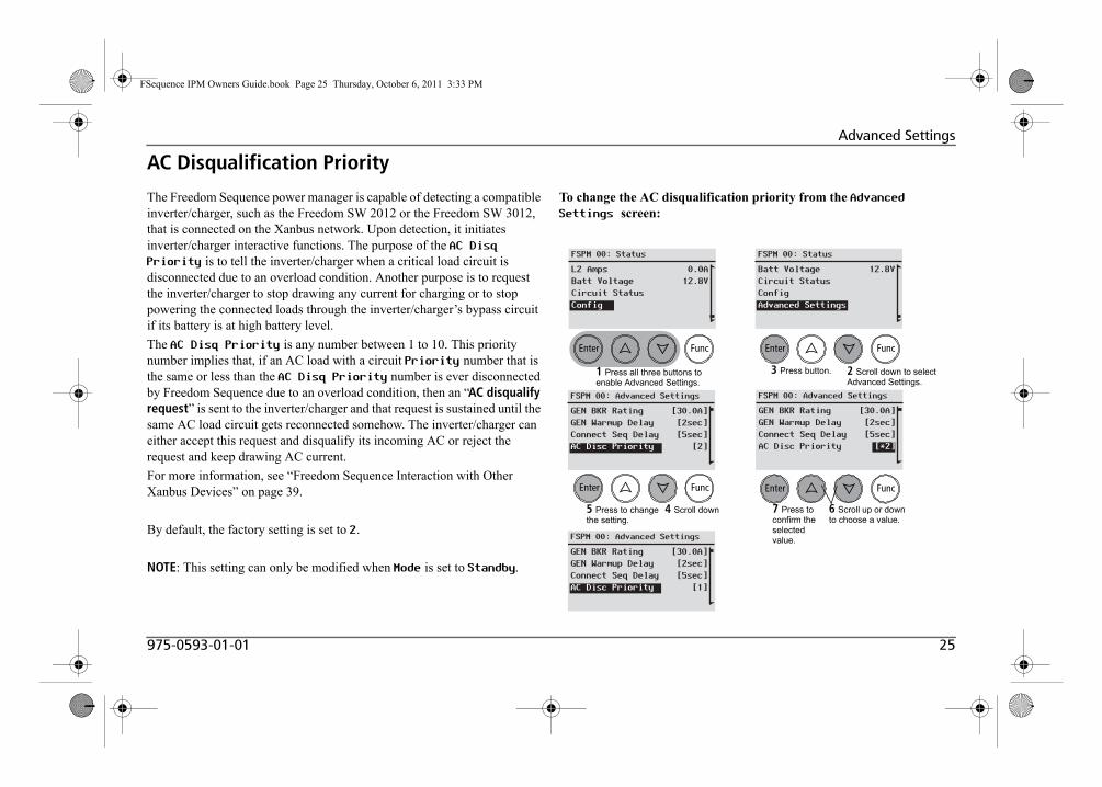
AC Disqualification Priority
The Freedom Sequence power manager is capable of detecting a compatible inverter/charger, such as the Freedom SW 2012 or the Freedom SW 3012, that is connected on the Xanbus network. Upon detection, it initiates inverter/charger interactive functions. The purpose of the AC Disq Priority is to tell the inverter/charger when a critical load circuit is disconnected due to an overload condition. Another purpose is to request the inverter/charger to stop drawing any current for charging or to stop powering the connected loads through the inverter/charger’s bypass circuit if its battery is at high battery level.
The AC Disq Priority is any number between 1 to 10. This priority number implies that, if an AC load with a circuit Priority number that is the same or less than the AC Disq Priority number is ever disconnected by Freedom Sequence due to an overload condition, then an “AC disqualify request” is sent to the inverter/charger and that request is sustained until the same AC load circuit gets reconnected somehow. The inverter/charger can either accept this request and disqualify its incoming AC or reject the request and keep drawing AC current.
For more information, see “Freedom Sequence Interaction with Other Xanbus Devices” on page 39.
By default, the factory setting is set to 2.
NOTE: This setting can only be modified when Mode is set to Standby.
To change the AC disqualification priority from the Advanced Settings screen:
FSPM 00: Status
L2 AmpsBatt VoltageCircuit StatusConfig
0.0A12.8V
FSPM 00: Status
Batt VoltageCircuit StatusConfigAdvanced Settings
12.8V
FSPM 00: Advanced Settings
GEN BKR RatingGEN Warmup DelayConnect Seq DelayAC Disc Priority
[30.0A][2sec][5sec]
[2]
FSPM 00: Advanced Settings
GEN BKR RatingGEN Warmup DelayConnect Seq DelayAC Disc Priority
[30.0A][2sec][5sec][*2]
FSPM 00: Advanced Settings
GEN BKR RatingGEN Warmup DelayConnect Seq DelayAC Disc Priority
[30.0A][2sec][5sec]
[1]
1 Press all three buttons to enable Advanced Settings.
2 Scroll down to select Advanced Settings.
5 Press to change the setting.
6 Scroll up or down to choose a value.
3 Press button.
7 Press to confirm the selected value.
4 Scroll down
FSequence IPM Owners Guide.book Page 25 Thursday, October 6, 2011 3:33 PM

26 Freedom Sequence Intelligent Power Manager Owner’s Guide
Advanced Settings
DC Voltage SettingThe Freedom Sequence power manager can be used with a 12-volt or24-volt battery system. Depending on which battery system is used, the power manager can be set correspondingly to either 12.0V or 24.0V.
All four DC relays will have default settings for each battery trigger set/clear values based on the selected value of the DC Voltage setting. See “Battery Voltage Triggers” on page 32.
By default, the factory setting is set to 12.0 V.
NOTE: This setting can only be modified when Mode is set to Standby.
To change the DC voltage setting from the Advanced Settings screen:
FSPM 00: Status
L2 AmpsBatt VoltageCircuit StatusConfig
0.0A12.8V
FSPM 00: Status
Batt VoltageCircuit StatusConfigAdvanced Settings
12.8V
FSPM 00: Advanced Settings
GEN Warmup DelayConnect Seq DelayAC Disc PriorityNom DC Voltage
[30.0A][2sec][5sec][12.0V]
FSPM 00: Advanced Settings
GEN Warmup DelayConnect Seq DelayAC Disc PriorityNom DC Voltage
[30.0A][2sec][5sec]
[*12.0V]
FSPM 00: Advanced Settings
GEN Warmup DelayConnect Seq DelayAC Disc PriorityNom DC Voltage
[30.0A][2sec][5sec][24.0V]
1 Press all three buttons to enable Advanced Settings.
2 Scroll down to select Advanced Settings.
5 Press to change the setting.
6 Scroll up or down to choose a value.
3 Press button.
7 Press to confirm the selected value.
4 Scroll down
FSequence IPM Owners Guide.book Page 26 Thursday, October 6, 2011 3:33 PM

975-0593-01-01 27
Circuit Level Advanced Settings
Figure 11 Freedom Sequence Circuit Level Advanced Settings
Enter Func Enter Func
FSPM 00: Status
Batt VoltageCircuit StatusConfigAdvanced Settings
12.8V
FSPM 00: Circuit 2
Circuit NameLoad ShedCircuit TypeAC LinePriorityReconnect MRGNGEN Soft StartBatt Low Trig SetBatt Low Trig ClrBatt High Trig ClrBatt High Trig Set
[ACLoad2][Enabled]
[ACInputOut][Line1]
[2][10%]
[Disable][10.5V][11.0V][14.0V][14.5V]
FSPM 00: Advanced Settings
[30.0A][0sec][10sec]
[2]
GEN BKR RatingGEN Warmup DelayConnect Seq DelayAC Disc Priority
Enter Func
FSPM 00: Advanced Settings
[10sec][2]
Connect Seq DelayAC Disq PriorityCircuit1Circuit2
FSPM 00: Circuit 2
[ACLoad2][Enabled]
[ACInputOut][Line1]
Circuit NameLoad ShedCircuit TypeAC Line
Complete list of circuit-level advanced settings. Each relay will have the same settings. However, AC relay settings do not apply to DC relays and vice versa.
Once the Advanced Settings item appears from the Device Status screen, scroll down (1) until Advanced Settings is highlighted then, press Enter (2) to bring up the Advanced Settings screen.
1 432
To activate a circuit-level advanced settings item, move through each item using the Up and Down buttons (3).
When a circuit is selected, press the Enter button (4) to activate the advanced settings of that particular circuit.
FSequence IPM Owners Guide.book Page 27 Thursday, October 6, 2011 3:33 PM

28 Freedom Sequence Intelligent Power Manager Owner’s Guide
Circuit Level Advanced Settings
AC Relay SettingsThe Freedom Sequence has AC relays1 that can each be used to control an AC load up to 15 amps. Each AC relay has a unique internal identifier (for example, Circuit1, Circuit2, etc.) Freedom Sequence allows the AC relays to be configured with a variety of settings to best manage the AC power on the system. The following settings can be configured for all AC relays.
• Circuit Name (page 29)• Load Shed (page 30) • Circuit Type (page 30)• AC Line (page 30)• Priority (page 31)• Reconnect MRGN (page 32)
DC Relay SettingsThe Freedom Sequence has DC relays2 which can be used to connect and disconnect DC loads on the system based on battery voltage thresholds. The following settings can be configured for all DC relays.
• Circuit Name (page 29)• Load Shed (page 30)• Circuit Type (page 30)• Gen Soft Start (page 31)• Batt Low Trig Set (page 32)• Batt Low Trig Clr (page 32)• Batt High Trig Clr (page 32)• Batt High Trig Set (page 32)
1.Six AC relays for PN: 809-0912 and four AC relays for PN: 809-0913. 2.Four DC relays for both PNs: 809-0912 and 809-0913.
FSequence IPM Owners Guide.book Page 28 Thursday, October 6, 2011 3:33 PM

975-0593-01-01 29
Circuit Level Advanced Settings
Circuit Name
All the AC and DC relays of Freedom Sequence can be assigned a circuit name1 (a label) from the Xanbus SCP or XDT2 tool. The label for each of these relays can be up to ten alpha-numeric characters.
The benefit of labelling the relays are for customizing and ease of use.
To change the Circuit Name from the Advanced Settings screen:1. Press the Enter button to activate the circuit setup screen for the
selected circuit.2. Press the Enter button on the Circuit Name field.3. Press the Func button to erase the characters one by one, except the last
character. Erasing all characters will put you back to step 2.4. Use the arrow buttons to scroll through the character set.5. Press the Enter button to confirm a character selection. Repeat 4 and 5
to form a new circuit name, up to ten characters.6. Press the Enter button again on the last character to confirm the new
circuit label.
NOTE: This setting can only be modified when Desired Mode is set to Standby.
1.Circuit names can be up to ten characters long. Valid characters are from a to z, A to Z, 0 to 9,symbols '/' (forward slash) and '-'(hyphen). Spaces, underscore and period are not accepted symbols.2.The XDT tool is available for OEMs only.
Relay ID Default Circuit Name Possible New Name Circuit1 ACLoad1 Main-A/C
Circuit2 ACLoad2 Space-heat
Circuit3 ACLoad3 Dishwasher
Circuit4 ACLoad4 Refrigerat
Circuit5 ACLoad5 H2O-Heater
Circuit6 ACLoad6 WallOutlet
Circuit7 DCLoad1 Thermostat
Circuit8 DCLoad2 and so on...Circuit9 DCLoad3
Circuit10 DCLoad4
FSPM 00: Circuit 3
Circuit NameOver-rideTypeLine Association
[ACLoad3][Disabled]
[ACInputOut][Line1]
FSPM 00: Circuit 3
Circuit NameOver-rideTypeLine Association
[ACLoad2][Disabled]
[ACInputOut][Line1]
FSPM 00: Advanced Settings
Circuit1Circuit2Circuit3Circuit4
FSPM 00: Circuit 3
Circuit NameOver-rideTypeLine Association
[D][Disabled]
[ACInputOut][Line1]
FSPM 00: Circuit 3
Circuit NameOver-rideTypeLine Association
[Dishwasher][Disabled]
[ACInputOut][Line1]
FSPM 00: Circuit 3
Circuit NameOver-rideTypeLine Association
[Dishwasher][Disabled]
[ACInputOut][Line1]
1 2
3 45
6
FSequence IPM Owners Guide.book Page 29 Thursday, October 6, 2011 3:33 PM
30 Freedom Sequence Intelligent Power Manager Owner’s Guide
Circuit Level Advanced Settings
Load Shed
The Load Shed setting here is the same as the setting discussed in “Load Shed” on page 19. The only difference here is that the change in load shed setting happens from the circuit-level screen in Advanced Settings instead of from the Config screen.
Circuit Type
The Freedom Sequence power manager’s circuit relays can control either AC or DC lines. If the circuit relay controls an AC line, its type is ACInputOut. If the circuit relay controls a DC line, its type is DCInputOut. AC relay types cannot be modified to DCInputOut. However, a DC relay type can be modified to ACInputOut when that DC relay is used to control an AC appliance.
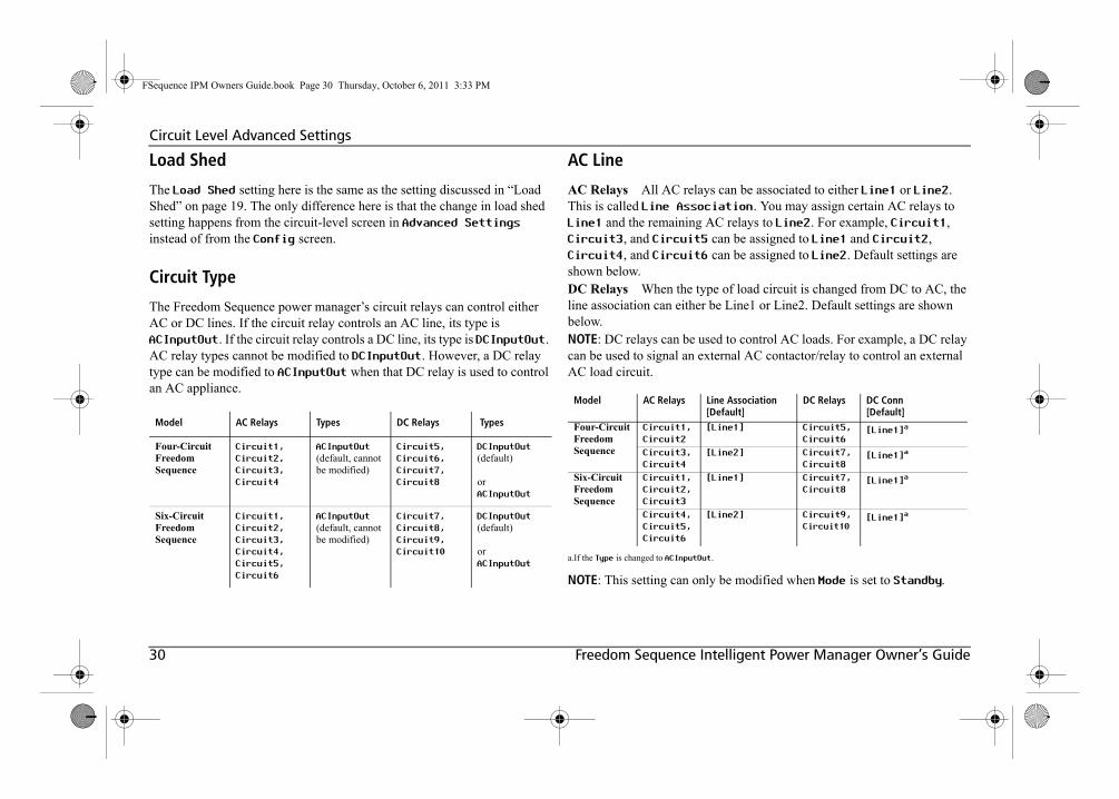
AC Line
AC Relays All AC relays can be associated to either Line1 or Line2. This is called Line Association. You may assign certain AC relays to Line1 and the remaining AC relays to Line2. For example, Circuit1, Circuit3, and Circuit5 can be assigned to Line1 and Circuit2, Circuit4, and Circuit6 can be assigned to Line2. Default settings are shown below.DC Relays When the type of load circuit is changed from DC to AC, the line association can either be Line1 or Line2. Default settings are shown below. NOTE: DC relays can be used to control AC loads. For example, a DC relay can be used to signal an external AC contactor/relay to control an external AC load circuit.
NOTE: This setting can only be modified when Mode is set to Standby.
Model AC Relays Types DC Relays Types
Four-Circuit Freedom Sequence
Circuit1,
Circuit2,
Circuit3,
Circuit4
ACInputOut
(default, cannot be modified)
Circuit5,
Circuit6,
Circuit7,
Circuit8
DCInputOut
(default)
orACInputOut
Six-Circuit Freedom Sequence
Circuit1,
Circuit2,
Circuit3,
Circuit4,
Circuit5,
Circuit6
ACInputOut
(default, cannot be modified)
Circuit7,
Circuit8,
Circuit9,
Circuit10
DCInputOut
(default)
orACInputOut
Model AC Relays Line Association[Default]
DC Relays DC Conn[Default]
Four-Circuit Freedom Sequence
Circuit1,
Circuit2
[Line1] Circuit5,
Circuit6[Line1]a
a.If the Type is changed to ACInputOut.
Circuit3,
Circuit4
[Line2] Circuit7,
Circuit8[Line1]a
Six-Circuit Freedom Sequence
Circuit1,
Circuit2,
Circuit3
[Line1] Circuit7,
Circuit8[Line1]a
Circuit4,
Circuit5,
Circuit6
[Line2] Circuit9,
Circuit10[Line1]a
FSequence IPM Owners Guide.book Page 30 Thursday, October 6, 2011 3:33 PM

975-0593-01-01 31
Circuit Level Advanced Settings
Priority
The Priority setting here is the same as the priority setting discussed in “Circuit Priority” on page 17. The only difference here is that the change in priority setting happens from the circuit-level screen in Advanced Settings instead of from the Config screen.
Generator Soft Start
The purpose of having a generator soft start (GEN Soft Start) feature is to allow generators to be loaded gradually after the transfer switch flips from shore power to generator or when the generator is started. Without engaging the GEN Soft Start feature, all the load circuits controlled by Freedom Sequence will abruptly get connected to generator power. This may cause the generator to experience a step load which may cause its voltage/ frequency to dip and in turn cause nuisance tripping of sensitive loads.Each relay of Freedom Sequence that is associated to Line1 or Line2 can beindividually configured to two GEN Soft Start settings: Enabled or Disabled.By default, all relays associated to Line1 or Line2 are set to Disabled.
When Freedom Sequence receives the Generator Run (B+) signal high, it will trigger the AC relays to disconnect load circuits that have GEN Soft Start configured to Enabled. For AC relays configured to Disabled, those AC relays will remain connected during the GEN Soft Start process. After the Generator Run (B+) signal goes high, Freedom Sequence will apply the Gen Warmup Delay. At the end of this Gen Warmup Delay, the Freedom Sequence power manager assumes the transfer switch has
toggled and the power manager starts to reconnect the AC relays that have been set to Enabled. Freedom Sequence will sequentially start to reconnect all the load circuits in the priority order defined for AC relays.
EXCEPTION: If an AC load Circuit3 is set to a lower priority than an AC load Circuit2 with a Generator Soft Start setting of Enabled, Circuit3 will get disconnected to avoid a priority inversion1.
1.A priority inversion occurs when an AC load that has a higher circuit priority gets disconnectedfirst before another AC load that has a lower circuit priority.
AC LOADCircuit1Circuit2Circuit3
GEN SOFT STARTDisabledEnabledDisabled
STATUSONONON
PRIORITY[1][2][3]
GENERATOR IS OFF
AC LOADCircuit1Circuit2Circuit3
GEN SOFT STARTDisabledEnabledDisabled
STATUSONOFFOFF
PRIORITY[1][2][3]
DURING GEN WARM UP DELAY
AC LOADCircuit1Circuit2Circuit3
GEN SOFT STARTDisabledEnabledDisabled
STATUSONONON
PRIORITY[1][2][3]
GENERATOR IS ON
SHORE GEN
SHORE GEN
SHORE GEN
Circuit3 will get disconnected to avoid tripping due to priority inversion.
Circuit2 will get reconnected first then Circuit3 follows, once the generator power has been fully ramped up and stabilized.
FSequence IPM Owners Guide.book Page 31 Thursday, October 6, 2011 3:33 PM
32 Freedom Sequence Intelligent Power Manager Owner’s Guide
Circuit Level Advanced Settings
Reconnect Margin
When a load circuit connected to either Line1 or Line2 is shed by Freedom Sequence to avoid an overload condition, Freedom Sequence stores in its memory the current that load circuit was drawing before it got shed (that is, Last Load Shed current).
The Freedom Sequence continuously checks for the Headroom Current1 and compares it with the Current To Reconnect value for the circuit. If the Headroom Current is more than the Current To Reconnect for a time-period that is more than the Connect Sequence Delay setting, Freedom Sequence will reconnect that circuit.
Current To Reconnect is calculated based on Reconnect MGN and Last Load Shed.
For example, if Circuit1 was set to a reconnect margin of 20% and the Last Load Shed current in memory was 10 amps, Freedom Sequence will wait for a Current To Reconnect of 12 amps calculated as:
Last Load Shed + (20% × Last Load Shed),
to be available before reconnecting the circuit.
By default, the factory setting of Reconnect MGN for all AC relaysis set to 10%.
Battery Voltage Triggers
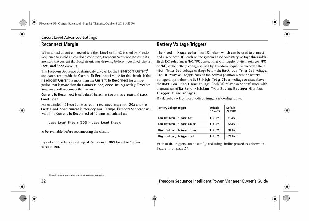
The Freedom Sequence has four DC relays which can be used to connect and disconnect DC loads on the system based on battery voltage thresholds. Each DC relay has a N/O/N/C contact that will toggle (switch between N/O or N/C) if the battery voltage sensed by Freedom Sequence exceeds a Batt High Trig Set voltage or drops below the Batt Low Trig Set voltage. The DC relay will toggle back to the normal position when the battery voltage drops below the Batt High Trig Clear voltage or rises above the Batt Low Trig Clear voltage. Each DC relay can be configured with a unique set of Battery High/Low Trig Set and Battery High/Low Trigger Clear voltages.
By default, each of these voltage triggers is configured to:
Each of the triggers can be configured using similar procedures shown in Figure 11 on page 27.
1.Headroom current is also known as available capacity.
Battery Voltage Trigger Default12-volts
Default24-volts
Low Battery Trigger Set [10.5V] [21.0V]
Low Battery Trigger Clear [11.0V] [22.0V]
High Battery Trigger Clear [14.0V] [28.0V]
High Battery Trigger Set [14.5V] [29.0V]
FSequence IPM Owners Guide.book Page 32 Thursday, October 6, 2011 3:33 PM
975-0593-01-01 33
Freedom Sequence Operational Concepts
Auto-Detection of AC Input Source(Shore/Gen)The Freedom Sequence power manager can be wired to a transfer switch that is connected to either a shore power or a generator power source. When AC voltage is detected at the input terminal of the Freedom Sequence, the AC source is assumed to be coming from shore power if the B+ signal is not active. Freedom Sequence detects the B+ signal two ways: via the Xanbus Automatic Generator Start (AGS) on the Xanbus network or through the presence of 12 volts on the B+ signal wired to the DC auxiliary connector port. The Freedom Sequence power manager assumes a generator power source is On when a high B+ signal is detected from either source.
Auto-Detection of AC Input Source Type (1-Ph/2-Ph)The AC source connected at both Line1 and Line2 of the Freedom Sequence power manager can be either Split phase or Single phase.
• Single phase is determined when 120 volts is measured between Line1-to-Neutral or Line2-to-Neutral or both, and there is no phase difference between the voltages measured.
• Split phase is determined when 240 volts is measured between Line1and Line2 and that the voltages are found out of phase by more than 100 degrees.
Loading of Shore/Generator Breaker RatingsThe Freedom Sequence has the ability to automatically change the breaker settings from shore power (Shore Breaker) to generator power (Generator Breaker) when it detects the B+ signal. At any time if the B+ signal goes low, the Freedom Sequence will instantly switch to the shore breaker setting.
IMPORTANT: The Freedom Sequence power manager automatically sets a ceiling on the current that’s coming from either input sources. The goal of this ceiling (current clamp) is to avoid current draw in the RV from tripping the input source’s breaker when an overload occurs within the RV's power system. Instead, the power manager’s AC Load Shedding (see next page) logic will determine which loads to disconnect within the power system while staying within the current clamp value. The current clamp is always 80% of the breaker rating of the input source. For example, if the shore breaker in an RV Camp is set to 50 amps then, the current clamp is 80% of 50, which is 40 amps. However, when BRK Derating is disabled, the current clamp is 100% of the breaker rating. See “Breaker Derating” on page 22.
FSequence IPM Owners Guide.book Page 33 Thursday, October 6, 2011 3:33 PM

34 Freedom Sequence Intelligent Power Manager Owner’s Guide
Freedom Sequence Operational Concepts
AC Load Shedding
When the current draw from the main AC source increases beyond the current clamp, Freedom Sequence power manager starts to shed (to disconnect) AC load circuits in a priority order set by the installer. Circuits having the lowest ranking priority gets shed first.
Freedom Sequence takes into account the Line Association of a circuit for load shedding when it operates with a split phase AC source. It will shed the circuit with lowest ranking priority with the group of circuits associated to the line that is overloaded.
When it operates from a single phase supply, Freedom Sequence does not check for line association before shedding the lowest ranking priority load circuit.
After an overload condition is detected, Freedom Sequence waits for two seconds to check if the overload persists before disconnecting a load circuit. If the overload condition is corrected it will not disconnect any load circuit, otherwise, it will shed the lower ranking priority circuit.
If disconnecting of one load circuit was not enough to correct the overload condition, the power manager will continue to shed the next lowest priority ranking load that is On until the overload condition is corrected.
The Freedom Sequence power manager keeps in its onboard memory the current each load circuit was drawing before it got disconnected. This current is displayed on the SCP as the Last Shed Current. The power manager uses the two values, Reconnect MRGN and Last Shed Current to determine if adequate headroom of current is available to reconnect the load circuit. If the headroom of current was available throughout the Connect Seq Delay period the power manager would reconnect the
circuit. However, if during this Connect Seq Delay period the available headroom falls below the Reconnect MRGN plus Last Shed Current then, the power manager will not reconnect the circuit.
The Freedom Sequence power manager will reconnect circuits in the order of highest ranking load circuit in the Off setting. When operating on a split-phase AC, the power manager will reconnect specifically those load circuits which are associated to the line that has adequate headroom.
While operation on a single-phase AC, the power manager will not check for line associations.
See the illustration on the next page.
FSequence IPM Owners Guide.book Page 34 Thursday, October 6, 2011 3:33 PM

975-0593-01-01 35
Freedom Sequence Operational Concepts
Figure 12 AC Load Shedding Illustration
Desired ModeSHR BKR ModeSHR BKR RatingGEN BKR RatingAC-FrontAC-CentralSpace HeatWasherDryerElec RangeCircuit7Circuit8Circuit9Circuit10Sequence DelayAC Disc Priority
[Operating][Manual][30.0A][20.0A]
[1][3][6][2][4][5]
[][][][]
[10sec][2]
AC Src TypeAC SourceAMPS L1AMPS L2Batt LevelAC-FrontAC-CentralSpace HeatWasherDryerElec RangeCircuit7Circuit8Circuit9Circuit10Config FSPMAdvanced Settings
2-PhShore135.0A15.0A12.0V
On 10.0AOn 15.0AOn 10.0AOn 6.0AOn 4.0AOn 5.0AOn 0.0AOn 0.0AOn 0.0AOn 0.0A
AC Src TypeAC SourceAMPS L1AMPS L2Batt LevelAC-FrontAC-CentralSpace HeatWasherDryerElec RangeCircuit7Circuit8Circuit9Circuit10Config FSPMAdvanced Settings
2-PhShore125.0A15.0A12.0V
On 10.0AOn 15.0AOff 0.0AOn 6.0AOn 4.0AOn 5.0AOn 0.0AOn 0.0AOn 0.0AOn 0.0A
STATUS AT OVERLOADPRESENT CONFIGURATION
LINE1 (L1)
LINE2 (L2)
STATUS AFTER LOAD SHEDDING EVENT
Look at the highlighted AC circuits. Notice the priority settings for each circuit (1).Also, observe that the SHR BKR Rating is set to 30 amps (2).
Line1 is experiencing an overload condition at 35 amps (3) exceeding the SHR BKR Rating of 30 amps by 5 amps.At this point, Freedom Sequence will apply its load shedding logic to all circuits in Line1 and shed the load that has the lowest priority setting. In this case, that load is Space Heat with a priority setting of 6.
After the load shedding event, Freedom Sequence will report Space Heat as Off 0.0A (4).Line1 is no longer in overload condition at 25 amps (5) not exceeding the SHR BKR Rating of 30 amps.
1
23 5
4
FSequence IPM Owners Guide.book Page 35 Thursday, October 6, 2011 3:33 PM

36 Freedom Sequence Intelligent Power Manager Owner’s Guide
Freedom Sequence Operational Concepts
DC Load SheddingThe Freedom Sequence continuously monitors the battery voltage and compares it against the four voltage settings to set the trigger and clear the trigger of a DC relay on a High Battery Voltage setpoint as well as a Low Battery Voltage setpoint.
The Freedom Sequence power manager measures the battery voltage from the DC power terminals of the auxiliary connector port. If Xantrex devices exist on the Xanbus network, the power manager will use the battery voltage reported by these devices in a preferential order by source as:
Battery monitor >> charge controller >> inverter/charger
The Trigger Set and Trigger Clear are absolute setpoints and don’t take into account the duration for how long the battery voltage will be low before triggering the DC relay. Each of the DC relays has a N/O and N/C contact point which will toggle to Closed and Open positions respectively when a DC relay is triggered.
Using DC Relay to control AC load circuitsThe DC Relays can also be used to shed AC load circuits if a DC Relay is used to control the external AC Relay. This can be done by going to the DC Relay configuration menu and selecting its association to Line1.
When the association is changed to Line1, all the configuration fields for the DC relay will change to those found for the AC relay, allowing to define Priority, Reconnect MRGN, Gen Soft-Start option, et cetera.
The Freedom Sequence does not have a current sensor to allow continuous monitoring of the current draw by the load circuit that this DC relay controls and therefore, it will show as N/A on the SCP.
However, the Freedom Sequence automatically calculates the decrease in current achieved by disconnecting the AC load circuit that is indirectly controlled through this DC relay and shows it as Last-Load Shed current.
FSequence IPM Owners Guide.book Page 36 Thursday, October 6, 2011 3:33 PM

975-0593-01-01 37
Freedom Sequence Operational Concepts
Priority Swapping Between CircuitsThe Freedom Sequence power manager allows the user to change the prioritization of the AC load circuits. A typical instance would be when an RV is used in a warm climate, the air conditioner would have a higher priority than the space heater or engine block heater. Conversely, in cold climates, the space heater or engine block heater needs to have priority over the air conditioner. The power manager allows changing priority of an AC load circuit through the Config screen of the SCP (“Circuit Priority” on page 17) or through the Circuit Level Advanced Settings screen (“Priority” on page 31). The power manager adjusts the priority settings for the rest of the circuits automatically based on the new priority number that was assigned to an AC load circuit.
For example (see illustration), if the priority of Engine Block Heater is changed from 4 to 1, the power manager will assign the Engine Block Heater its new priority rank of 1 and automatically swap and adjust priority settings for the rest of the circuits.
IMPORTANT: When reprogramming default circuit priority settings, always consult a professional installer from your RV dealership.
TO
TO
TO
TO
TO
FSequence IPM Owners Guide.book Page 37 Thursday, October 6, 2011 3:33 PM
38 Freedom Sequence Intelligent Power Manager Owner’s Guide
Freedom Sequence Operational Concepts
Override the AC Circuit Load SheddingThe Freedom Sequence power manager provides a feature to override the load shed priority (Load Shed setting) for an AC load circuit that was disconnected by either an AC relay or a DC relay. This allows the user the flexibility to force an AC load to turn On for just a few minutes without the need to change the priority order of all AC load circuits. When an AC load circuit’s Load Shed setting is Disabled, the power manager will skip this circuit from the load shed sequence and treat it as a non-controlled AC load on the system.
IMPORTANT: When reprogramming default circuit priority settings, always consult a professional installer from your RV dealership.
FSequence IPM Owners Guide.book Page 38 Thursday, October 6, 2011 3:33 PM
975-0593-01-01 39
Freedom Sequence Operational Concepts
Freedom Sequence Interaction with Other Xanbus Devices
Battery Voltage Measurement
The Freedom Sequence power manager measures the battery voltage from the DC power terminals of the auxiliary connector port. If Xantrex devices exist on the Xanbus network, the power manager will use the battery voltage reported by these devices in a preferential order by source as:
Battery monitor >> charge controller >> inverter/charger
Generator Run Detection B+ Signal
Freedom Sequence detects the B+ signal via the presence of a Xanbus AGS on the Xanbus network or through the presence of +12V on B+ signal wired to the auxiliary connector port. If the B+ signal from either source is detected to be high, the Freedom Sequence assumes the generator is On.
Freedom SW Interactive Charger De-rating (ICD)
The use of Freedom Sequence on an RV along with Freedom SW 3012 or Freedom SW 2012 inverter/charger can further optimize the usage of available power. An inverter/charger draws current from the AC source only when it is in a non-inverting mode (that is, bypass only or charging with bypass mode). The inverter/charger is usually connected directly to a distribution panel and therefore Freedom Sequence cannot have any direct control over the current drawn by charger or bypass loads. However, if the
inverter/charger is a Xanbus-enabled device and is programmed to support Freedom Sequence, then the current draw by the charger can be regulated to assist in optimizing the use of available power.
For example, in a typical operating case, Freedom Sequence continually monitors the current usage of the AC source. The difference between current clamp settings and current draw from the AC source is defined as the headroom current or “available capacity”. Freedom Sequence continually broadcasts this information on the Xanbus network. It is possible to reduce the AC current used for charging batteries to a level that allows other loads with intermittent current needs to operate. As the charger continuously listens to the available capacity reported by Freedom Sequence and controls its current draw for charging, the available capacity remains minimum but never negative. The charger will discard derating charger current if the battery is in a state of equalizing.
Freedom SW AC Disqualify On Request (ACDR)
ACDR is a feature that allows Freedom Sequence to send a message to the inverter/charger to stop drawing current in bypass and charger mode. And if the inverter mode is enabled, then the loads connected to the inverter will be powered from the inverter/charger’s connected battery. The purpose of ACDR is to reduce current draw from the input AC source and instead use stored energy from the battery.
FSequence IPM Owners Guide.book Page 39 Thursday, October 6, 2011 3:33 PM
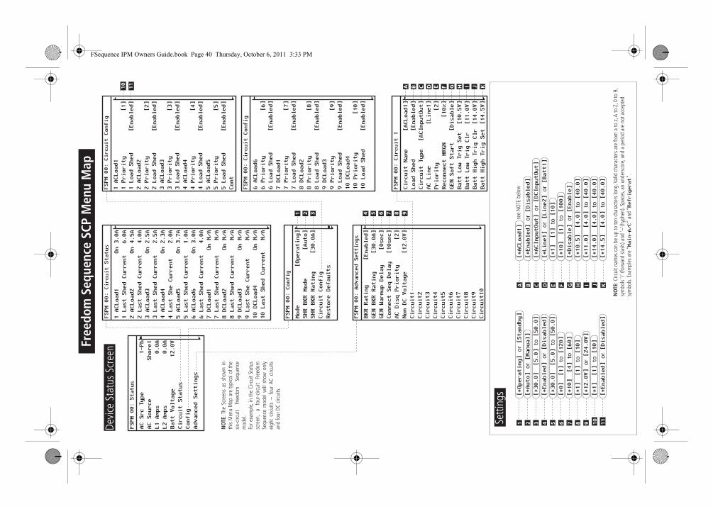
40 Freedom Sequence Intelligent Power Manager Owner’s Guide
Freedom Sequence SCP Menu Map
Freedom Sequence SCP Menu MapFSPM 00: Status
AC Src Type
AC Source
L1 Amps
L2 Amps
Batt Voltage
Circuit Status
Config
Advanced Settings
1-Ph
Shore1
0.0A
0.0A
12.0V
1 ACLoad1
1 Last Shed Current
2 ACLoad2
2 Last Shed Current
3 ACLoad3
3 Last Shed Current
4 ACLoad4
4 Last She Current
5 ACLoad5
5 Last Shed Current
6 ACLoad6
6 Last Shed Current
7 DCLoad1
7 Last Shed Current
8 DCLoad2
8 Last Shed Current
9 DCLoad3
9 Last She Current
10 DCLoad4
10 Last Shed CurrentOn 3.0A
6.0A
On 4.5A
4.0A
On 2.5A
2.5A
On 2.3A
2.0A
On 3.7A
1.0A
On 3.0A
4.0A
On N/A
N/A
On N/A
N/A
On N/A
N/A
On N/A
N/A
FSPM 00: Circuit Status
FSPM 00: Config
Mode
SHR BKR Mode
SHR BKR Rating
Circuit Config
Restore Defaults[Operating]
[Auto]
[30.0A]
FSPM 00: Circuit Config
1 ACLoad1
1 Priority
1 Load Shed
2 ACLoad2
2 Priority
2 Load Shed
3 ACLoad3
3 Priority
3 Load Shed
4 ACLoad4
4 Priority
4 Load Shed
5 ACLoad5
5 Priority
5 Load Shed
Cont
[1]
[Enabled]
[2]
[Enabled]
[3]
[Enabled]
[4]
[Enabled]
[5]
[Enabled]
FSPM 00: Circuit Config
6 ACLoad6
6 Priority
6 Load Shed
7 DCLoad1
7 Priority
7 Load Shed
8 DCLoad2
8 Priority
8 Load Shed
9 DCLoad3
9 Priority
9 Load Shed
10 DCLoad4
10 Priority
10 Load Shed
[6]
[Enabled]
[7]
[Enabled]
[8]
[Enabled]
[9]
[Enabled]
[10]
[Enabled]
FSPM 00: Advanced Settings
BKR Rating
GEN BKR Rating
GEN Warmup Delay
Connect Seq Delay
AC Disq Priority
Nom DC Voltage
Circuit1
Circuit2
Circuit3
Circuit4
Circuit5
Circuit6
Circuit7
Circuit8
Circuit9
Circuit10
[Enabled]
[30.0A]
[0sec]
[10sec]
[2]
[12.0V]
FSPM 00: Circuit 1
Circuit Name
Load Shed
Circuit Type
AC Line
Priority
Reconnect MRGN
GEN Soft Start
Batt Low Trig Set
Batt Low Trig Clr
Batt High Trig Clr
Batt High Trig Set[ACLoad1]
[Enabled]
[ACInputOut]
[Line1]
[2]
[10%]
[Disable]
[10.5V]
[11.0V]
[14.0V]
[14.5V]
1
10 11 A B C D E F G H I J K
2 3 4 5 6 7 8 9
1 2 3 4 5 6 7 8 9
[*Operating]
or [Standby]
[*30.0] [5.0]
to [50.0]
[*Auto]
or [Manual]
[*30.0] [5.0]
to [50.0]
[*0] [1]
to [120]
[*10] [4]
to [60]
[*1] [1]
to [10]
[*12.0V]
or [24.0V]
[*1] [1]
to [10]
10 11[*Enabled]
or [Disabled]
[*Enabled]
or [Disabled]
A B C D E F G H I J
[*Enabled]
or [Disabled]
[*ACInputOut]
or [DCInputOut]
[*Line1]
or [Line2]
or [Batt1]
[*1] [1]
to [10]
[*10] [1]
to [100]
[*Disable]
or [Enable]
[*10.5] [4.0]
to [40.0]
[*11.0] [4.0]
to [40.0]
[*14.0] [4.0]
to [40.0]
[*14.5] [4.0]
to [40.0]
K
[*ACLoad1]
NO
TE: C
ircui
t nam
es c
an b
e up
to te
n ch
arac
ters
long
. Val
id c
hara
cter
s ar
e fro
m a
to z
, A to
Z, 0
to 9
, sy
mbo
ls '/'
(for
war
d sla
sh) a
nd '–
'(hyp
hen)
. Spa
ces,
an u
nder
scor
e, a
nd a
per
iod
are
not a
ccep
ted
sym
bols.
Exa
mpl
es a
re “Main-A/C
” an
d “Refrigerat
”.
see
NOT
E be
low
Setti
ngs
Devi
ce S
tatu
s Sc
reen
Free
dom
Seq
uenc
e SC
P M
enu
Map
NO
TE: T
he S
cree
ns a
s sh
own
in
this
Men
u M
ap a
re ty
pica
l of t
he
six-c
ircui
t Fr
eedo
m
Sequ
ence
m
odel
.Fo
r exa
mpl
e, in
the
Circ
uit S
tatu
s sc
reen
, a
four
-circ
uit
Free
dom
Se
quen
ce m
odel
will
sho
w o
nly
eigh
t cir
cuits
– f
our
AC c
ircui
ts
and
four
DC
circu
its.
FSequence IPM Owners Guide.book Page 40 Thursday, October 6, 2011 3:33 PM
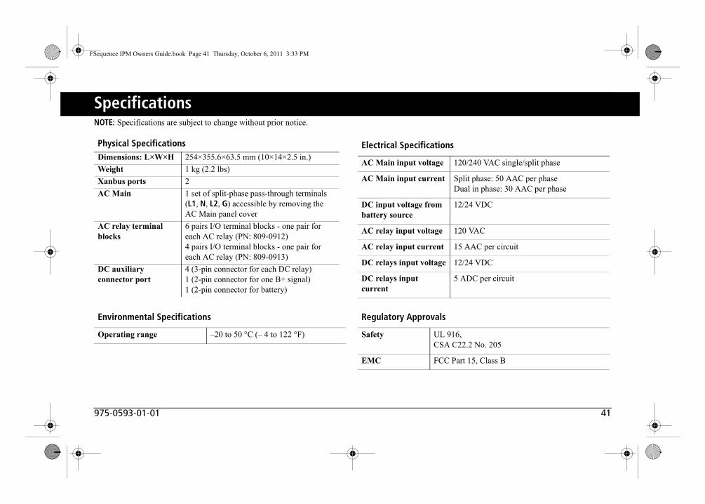
975-0593-01-01 41
SpecificationsNOTE: Specifications are subject to change without prior notice.
Physical SpecificationsDimensions: L×W×H 254×355.6×63.5 mm (10×14×2.5 in.)
Weight 1 kg (2.2 lbs)
Xanbus ports 2
AC Main 1 set of split-phase pass-through terminals (L1, N, L2, G) accessible by removing the AC Main panel cover
AC relay terminal blocks
6 pairs I/O terminal blocks - one pair for each AC relay (PN: 809-0912)4 pairs I/O terminal blocks - one pair for each AC relay (PN: 809-0913)
DC auxiliary connector port
4 (3-pin connector for each DC relay)1 (2-pin connector for one B+ signal)1 (2-pin connector for battery)
Environmental Specifications
Operating range –20 to 50 °C (– 4 to 122 °F)
Electrical Specifications
AC Main input voltage 120/240 VAC single/split phase
AC Main input current Split phase: 50 AAC per phaseDual in phase: 30 AAC per phase
DC input voltage from battery source
12/24 VDC
AC relay input voltage 120 VAC
AC relay input current 15 AAC per circuit
DC relays input voltage 12/24 VDC
DC relays input current
5 ADC per circuit
Regulatory Approvals
Safety UL 916,CSA C22.2 No. 205
EMC FCC Part 15, Class B
FSequence IPM Owners Guide.book Page 41 Thursday, October 6, 2011 3:33 PM

42 Freedom Sequence Intelligent Power Manager Owner’s Guide
Warranty and Return Information
WarrantyWhat does this warranty cover and how long does it last? This Limited Warranty is provided by Xantrex Technology Inc. (“Xantrex”) and covers defects in workmanship and materials in your Freedom Sequence Intelligent Power Manager. This warranty period lasts for 12 months from the date of purchase at the point of sale to you, the original end user customer, unless otherwise agreed in writing (the “Warranty Period”). You will be required to demonstrate proof of purchase to make warranty claims.This Limited Warranty is transferable to subsequent owners but only for the unexpired portion of the Warranty Period. Subsequent owners also require original proof of purchase as described in “What proof of purchase is required?”
What will Xantrex do? During the Warranty Period Xantrex will, at its option, repair the product (if economically feasible) or replace the defective product free of charge, provided that you notify Xantrex of the product defect within the Warranty Period, and provided that Xantrex through inspection establishes the existence of such a defect and that it is covered by this Limited Warranty. Xantrex will, at its option, use new and/or reconditioned parts in performing warranty repair and building replacement products. Xantrex reserves the right to use parts or products of original or improved design in the repair or replacement. If Xantrex repairs or replaces a product, its warranty continues for the remaining portion of the original Warranty Period or 90 days from the date of the return shipment to the customer, whichever is greater. All replaced products and all parts removed from repaired products become the property of Xantrex.Xantrex covers both parts and labor necessary to repair the product, and return shipment to the customer via a Xantrex-selected non-expedited surface freight within the contiguous United States and Canada. Alaska,
Hawaii and outside of the United States and Canada are excluded. Contact Xantrex Customer Service for details on freight policy for return shipments from excluded areas.
How do you get service? If your product requires troubleshooting or warranty service, contact your merchant. If you are unable to contact your merchant, or the merchant is unable to provide service, contact Xantrex directly at:
Direct returns may be performed according to the Xantrex Return Material Authorization Policy described in your product manual. For some products, Xantrex maintains a network of regional Authorized Service Centers. Call Xantrex or check our website to see if your product can be repaired at one of these facilities.
Telephone: 1 800 670 0707 (toll free North America)1 408 987 6030 (direct)
Fax: 1 800 994 7828 (toll free North America)
Email: [email protected]
Website: www.xantrex.com
FSequence IPM Owners Guide.book Page 42 Thursday, October 6, 2011 3:33 PM
975-0593-01-01 43
Warranty and Return InformationWhat proof of purchase is required? In any warranty claim, dated proof of purchase must accompany the product and the product must not have been disassembled or modified without prior written authorization by Xantrex. Proof of purchase may be in any one of the following forms:
• The dated purchase receipt from the original purchase of the product at point of sale to the end user; or
• The dated dealer invoice or purchase receipt showing original equipment manufacturer (OEM) status; or
• The dated invoice or purchase receipt showing the product exchanged under warranty.
What does this warranty not cover? Claims are limited to repair and replacement, or if in Xantrex's discretion that is not possible, reimbursement up to the purchase price paid for the product. Xantrex will be liable to you only for direct damages suffered by you and only up to a maximum amount equal to the purchase price of the product.This Limited Warranty does not warrant uninterrupted or error-free operation of the product or cover normal wear and tear of the product or costs related to the removal, installation, or troubleshooting of the customer's electrical systems. This warranty does not apply to and Xantrex will not be responsible for any defect in or damage to:a) the product if it has been misused, neglected, improperly installed,
physically damaged or altered, either internally or externally, or damaged from improper use or use in an unsuitable environment;
b) the product if it has been subjected to fire, water, generalized corrosion, biological infestations, or input voltage that creates operating conditions beyond the maximum or minimum limits listed in the Xantrex product specifications including but not limited to high input voltage from generators and lightning strikes;
c) the product if repairs have been done to it other than by Xantrex or its authorized service centers (hereafter “ASCs”);
d) the product if it is used as a component part of a product expressly warranted by another manufacturer;
e) component parts or monitoring systems supplied by you or purchased by Xantrex at your direction for incorporation into the product;
f) the product if its original identification (trade-mark, serial number) markings have been defaced, altered, or removed;
g) the product if it is located outside of the country where it was purchased; and
h) any consequential losses that are attributable to the product losing power whether by product malfunction, installation error or misuse.
FSequence IPM Owners Guide.book Page 43 Thursday, October 6, 2011 3:33 PM
44 Freedom Sequence Intelligent Power Manager Owner’s Guide
Warranty and Return Information
Disclaimer
Product
THIS LIMITED WARRANTY IS THE SOLE AND EXCLUSIVE WARRANTY PROVIDED BY XANTREX IN CONNECTION WITH YOUR XANTREX PRODUCT AND IS, WHERE PERMITTED BY LAW, IN LIEU OF ALL OTHER WARRANTIES, CONDITIONS, GUARANTEES, REPRESENTATIONS, OBLIGATIONS AND LIABILITIES, EXPRESS OR IMPLIED, STATUTORY OR OTHERWISE IN CONNECTION WITH THE PRODUCT, HOWEVER ARISING (WHETHER BY CONTRACT, TORT, NEGLIGENCE, PRINCIPLES OF MANUFACTURER'S LIABILITY, OPERATION OF LAW, CONDUCT, STATEMENT OR OTHERWISE), INCLUDING WITHOUT RESTRICTION ANY IMPLIED WARRANTY OR CONDITION OF QUALITY, MERCHANTABILITY OR FITNESS FOR A PARTICULAR PURPOSE. ANY IMPLIED WARRANTY OF MERCHANTABILITY OR FITNESS FOR A PARTICULAR PURPOSE TO THE EXTENT REQUIRED UNDER APPLICABLE LAW TO APPLY TO THE PRODUCT SHALL BE LIMITED IN DURATION TO THE PERIOD STIPULATED UNDER THIS LIMITED WARRANTY.
IN NO EVENT WILL XANTREX BE LIABLE FOR: (A) ANY SPECIAL, INDIRECT, INCIDENTAL OR CONSEQUENTIAL DAMAGES, INCLUDING LOST PROFITS, LOST REVENUES, FAILURE TO REALIZE EXPECTED SAVINGS, OR OTHER COMMERCIAL OR ECONOMIC LOSSES OF ANY KIND, EVEN IF XANTREX HAS BEEN ADVISED, OR HAD REASON TO KNOW, OF THE POSSIBILITY OF SUCH DAMAGE; (B) ANY LIABILITY ARISING IN TORT, WHETHER OR NOT ARISING OUT OF XANTREX'S NEGLIGENCE, AND ALL LOSSES OR DAMAGES TO ANY PROPERTY OR FOR ANY PERSONAL INJURY OR ECONOMIC LOSS OR DAMAGE CAUSED BY THE CONNECTION OF A PRODUCT TO ANY OTHER DEVICE OR SYSTEM; AND (C) ANY DAMAGE OR INJURY ARISING FROM OR AS A RESULT OF MISUSE OR ABUSE, OR THE INCORRECT INSTALLATION, INTEGRATION OR OPERATION OF THE PRODUCT BY PERSONS NOT AUTHORIZED BY XANTREX.
Exclusions
IF THIS PRODUCT IS A CONSUMER PRODUCT, FEDERAL LAW DOES NOT ALLOW AN EXCLUSION OF IMPLIED WARRANTIES. TO THE EXTENT YOU ARE ENTITLED TO IMPLIED WARRANTIES UNDER FEDERAL LAW, TO THE EXTENT PERMITTED BY APPLICABLE LAW THEY ARE LIMITED TO THE DURATION OF THIS LIMITED WARRANTY. SOME STATES, PROVINCES AND JURISDICTIONS DO NOT ALLOW LIMITATIONS OR EXCLUSIONS ON IMPLIED WARRANTIES OR ON THE DURATION OF AN IMPLIED WARRANTY OR ON THE LIMITATION OR EXCLUSION OF INCIDENTAL OR CONSEQUENTIAL DAMAGES, SO THE ABOVE LIMITATION(S) OR EXCLUSION(S) MAY NOT APPLY TO YOU. THIS LIMITED WARRANTY GIVES YOU SPECIFIC LEGAL RIGHTS. YOU MAY HAVE OTHER RIGHTS WHICH MAY VARY FROM STATE TO STATE, PROVINCE TO PROVINCE OR JURISDICTION TO JURISDICTION.
FSequence IPM Owners Guide.book Page 44 Thursday, October 6, 2011 3:33 PM

975-0593-01-01 45
Warranty and Return Information
Return Material Authorization PolicyFor those products that are not being repaired in the field and are being returned to Xantrex, before returning a product directly to Xantrex you must obtain a Return Material Authorization (RMA) number and the correct factory “Ship To” address. Products must also be shipped prepaid. Product shipments will be refused and returned at your expense if they are unauthorized, returned without an RMA number clearly marked on the outside of the shipping box, if they are shipped collect, or if they are shipped to the wrong location.When you contact Xantrex to obtain service, please have your instruction manual ready for reference and be prepared to supply:
• The serial number of your product• Information about the installation and use of the unit• Information about the failure and/or reason for the return• A copy of your dated proof of purchase
Record these details on page 46.
Return ProcedurePackage the unit safely, preferably using the original box and packing materials. Please ensure that your product is shipped fully insured in the original packaging or equivalent. This warranty will not apply where the product is damaged due to improper packaging.Include the following:
• The RMA number supplied by Xantrex Technology Inc. clearly marked on the outside of the box.
• A return address where the unit can be shipped. Post office boxes are not acceptable.
• A contact telephone number where you can be reached during work hours.
• A brief description of the problem.Ship the unit prepaid to the address provided by your Xantrex customer service representative.
If you are returning a product from outside of the USA or Canada In addition to the above, you MUST include return freight funds and are fully responsible for all documents, duties, tariffs, and deposits.
If you are returning a product to a Xantrex Authorized Service Center (ASC) A Xantrex return material authorization (RMA) number is not required. However, you must contact the ASC prior to returning the product or presenting the unit to verify any return procedures that may apply to that particular facility and that the ASC repairs this particular Xantrex product.
Out of Warranty ServiceIf the warranty period for your product has expired, if the unit was damaged by misuse or incorrect installation, if other conditions of the warranty have not been met, or if no dated proof of purchase is available, your unit may be serviced or replaced for a flat fee.To return your product for out of warranty service, contact Xantrex Customer Service for a Return Material Authorization (RMA) number and follow the other steps outlined in “Return Procedure” on page 45. Payment options such as credit card or money order will be explained by the Customer Service Representative. In cases where the minimum flat fee does not apply, as with incomplete units or units with excessive damage, an additional fee will be charged. If applicable, you will be contacted by Customer Service once your unit has been received.
FSequence IPM Owners Guide.book Page 45 Thursday, October 6, 2011 3:33 PM
46 Freedom Sequence Intelligent Power Manager Owner’s Guide
Warranty and Return Information
Information About Your SystemAs soon as you open your Freedom Sequence Intelligent Power Manager package, record the following information and be sure to keep your proof of purchase.
If you need to contact Customer Service, please record the following details before calling. This information will help our representatives give you better service.
❐ Serial Number ______________________❐ Product Number/s 809-0912, 809-0913❐ Purchased From ______________________❐ Purchase Date ______________________
❐ Type of installation (e.g. RV, truck)
______________________
❐ Length of time unit has been installed
______________________
❐ Battery/battery bank size ______________________❐ Battery type (e.g. flooded,
sealed gel cell, AGM)
______________________
❐ DC wiring size and length ______________________❐ Alarm sounding? ______________________❐ Description of indicators
on front panel
______________________
❐ Appliances operating when problem occurred
______________________
❐ Description of problem ______________________________________________________________________________________________________________________
FSequence IPM Owners Guide.book Page 46 Thursday, October 6, 2011 3:33 PM

FSequence IPM Owners Guide.book Page i Thursday, October 6, 2011 3:33 PM

Xantrex Technology USA Inc.
1 800 670 0707 Tel1 800 994 7828 Faxwww.xantrex.com
975-0593-01-01 Printed in China.
FSequence IPM Owners Guide.book Page ii Thursday, October 6, 2011 3:33 PM