FSAE Electronic Shifter · PDF file12/3/2012 · FSAE Electronic Shifter Final...
18
FSAE Electronic Shifter Final Project Report by Lee Redstone – [email protected] Lewis Weston – [email protected] Jason Deglint – [email protected] http://electronicshifter.wordpress.com/ Supervisor: Dr. Ashoka K.S. Bhat Group: 5 Due: December 3, 2012 Dept. Electrical and Computer Engineering University of Victoria All rights reserved. This report may not be reproduced in whole or in part, by photocopy or other means, without the permission of the author.
Transcript of FSAE Electronic Shifter · PDF file12/3/2012 · FSAE Electronic Shifter Final...
FSAE Electronic Shifter Final Project Report
by
Lee Redstone – [email protected] Lewis Weston – [email protected] Jason Deglint – [email protected]
http://electronicshifter.wordpress.com/
Supervisor: Dr. Ashoka K.S. Bhat
Group: 5
Due: December 3, 2012
Dept. Electrical and Computer Engineering University of Victoria
All rights reserved. This report may not be reproduced in whole or in part, by photocopy or
other means, without the permission of the author.

FSAE Electronic Shifter i
ELEC/CENG 399 Final Report Group #5
CONTENTS
1 – Project Goals ................................................................................................................ 1
3 – Detailed Project Description........................................................................................... 2
3.1 UVic Formula SAE ................................................................................................. 2
3.2 Shifting ................................................................................................................ 3
3.3 Current Shifter ...................................................................................................... 3
3.4 Pneumatic Design Consideration ............................................................................ 4
3.5 Electronic Shifter ................................................................................................... 5
3.6 Further Project Considerations ............................................................................... 5
4 – Workload Distribution ................................................................................................... 6
5 – Project Discussion ........................................................................................................ 6
5.1 Steering Wheel Connector ......................................................................................... 6
5.1.2 Extendable Connector ......................................................................................... 7
5.1.3 Removable Connector ......................................................................................... 7
5.1.4 Conclusions ........................................................................................................ 8
5. 2 Linear Actuator Selection and Testing ........................................................................ 9
5.2.1 Force Measurements ........................................................................................... 9
5.2.2 Push/Pull Solenoid .............................................................................................10
5. 3 Microcontroller ........................................................................................................10
5. 4 System Integration .................................................................................................10
6 – Summary and Future Work ..........................................................................................12
7 – Bibliography ................................................................................................................12
8 – Appendix ....................................................................................................................13

FSAE Electronic Shifter ii
ELEC/CENG 399 Final Report Group #5
LIST OF TABLES AND FIGURES
Table 1: Workload distribution ............................................................................................ 6
Table 2: Advantages and disadvantages of an extendable connector ...................................... 7
Table 3: Force table for shifting down .................................................................................. 9
Table 4: Force table for shifting up ...................................................................................... 9
Figure 1: Formula SAE car in action ..................................................................................... 3
Figure 2: Transmission pushrod........................................................................................... 3
Figure 3: Shift lever in cockpit ............................................................................................. 4
Figure 4: Steering wheel with shift button overlay ................................................................ 5
Figure 5: ¼ inch jack ......................................................................................................... 7
Figure 6: ¼ inch socket, single channel ............................................................................... 8
Figure 7: ¼ inch socket, dual channel ................................................................................. 8
Figure 8: ¼ inch jack inserted into single channel socket ...................................................... 8
Figure 9: Conceptual Block diagram showing The Simple System Operation ...........................11

FSAE Electronic Shifter 1
ELEC/CENG 399 Final Report Group #5
1 – PROJECT GOALS
There were 3 primary goals for the development of an Electronic Shifter for the UVic Formula
SAE team. These were decided upon at the onset of the project and were used to focus our
design objectives:
1. Redesign the shifting device for the UVic FSAE team`s prototype car.
The current shifting mechanism is a mechanical lever mounted on the side of the driver cockpit.
The lever requires the driver to remove one hand from the steering wheel while driving at high
speeds on a tight course. Driver performance could be improved by having button actuated
shifting from the steering wheel.
2. Maintain the reliability of the mechanical shifter
The current shifter is a simple mechanical device with a direct linkage to the transmission at the
rear of the car. One of the fundament challenges for the SAE team is system reliability, this
cannot be sacrificed, and all new developments need to be tested to ensure they are more
reliable than the previous design.
3. Practical Considerations
The new shifting device that is developed will play a vital role in the operation of the next car
the SAE team builds. Therefore, the design must be driven by the practical considerations that
the team will face when building and using the system. This includes the cost, and availability
of replacement parts

FSAE Electronic Shifter 2
ELEC/CENG 399 Final Report Group #5
2 – PROJECT OVERVIEW
The Formula SAE Team’s current vehicle uses mechanical linkage to allow the driver to change
gears. This configuration requires that the driver remove one hand from the steering wheel to
move the shift lever, which has the following drawbacks:
If shifting in the middle of a corner, the driver will only have one hand on the steering
wheel, reducing the amount of control they have of the vehicle
The time required to change gears is currently on the order of seconds
The solution to these drawbacks is to implement an electronic shifting mechanism with steering-
wheel -mounted buttons to control the up- and down-shifting. This allows the driver to keep
both hands on the steering wheel and may reduce the amount of time required for shifting by
an order of magnitude. The result of these modifications will be a safer, quicker vehicle.
3 – DETAILED PROJECT DESCRIPTION
This paper provides a complete report on the Electronic Shifter project undertaken for ELEC
399, during the Fall of 2012. The team successfully designed an electro-motive system capable
of changing the gears of a Formula SAE style race car. The following provides a background on
the UVic Formula SAE team and the intended application for this system.
3.1 UVIC FORMULA SAE
The UVic FSAE team competes annually in the Formula SAE competition hosted by the Society
of Automotive Engineers. The nature of the competition involves designing, fabricating and
constructing a new car each year. The majority of the components are designed specifically for
this purpose.
The team consists of 30 engineering undergraduate students, with approximately 80%
consisting of mechanical engineers. One of the major challenges for the team is system
integration, having all of the sub-systems working together in the tight confines of the car is a
never ending challenge.

FSAE Electronic Shifter 3
ELEC/CENG 399 Final Report Group #5
FIGURE 1: FORMULA SAE CAR IN ACTION
3.2 SHIFTING
The FSAE team powers its car using a Honda 600cc CBR F4i engine.
The engine block contains a six speed sequential transmission that is
normally shifted using the foot of the motorcycle driver. As the reader
can see in Figure 2, in order to shift up and down, two motions in
opposite directions are required.
3.3 CURRENT SHIFTER
The current device is a mechanical lever placed on the driver’s left hand side inside the cockpit.
Figure 3 shows the simple operation of the device, and the motion of the is translated to the
rear of the car using a heavy duty push/pull cable (shown in green in Figure 2)
FIGURE 2: TRANSMISSION PUSHROD

FSAE Electronic Shifter 4
ELEC/CENG 399 Final Report Group #5
FIGURE 3: SHIFT LEVER IN COCKPIT
3.4 PNEUMATIC DESIGN CONSIDERATION
The motion required to shift the gears of the engine is a simple bi-directional linear throw. A
pneumatic option was considered at the onset of the project; however there were a number of
considerations that led to the design being discarded:
1. Hoses: The transmission of the compressed air from the cylinders to the shifter would
require an extensive network of small diameter plastic hose. On a quickly moving race
car it is necessary to protect the entire length from chaffing on its mounts and touching
warm surfaces. It was decided that the risk of losing the ability to shift due to a hose
failure was too high to implement on the car.
2. Canisters: The compressed air canisters required for a pneumatic system weigh 8-12lbs.
The FSAE team has ambitious weight saving targets for this season, and were not
interested in adding excessive weight for a new shifting mechanism.
3. Consumables: Finally, there is only a finite number of shifts that can be stored in the
compressed air cylinders. It was deemed to be too high of a reliability risk to be able to
store sufficient gas for the entire duration of competition events.
It was for these reasons that an electronic shifter were chosen over a pneumatically powered
one.

FSAE Electronic Shifter 5
ELEC/CENG 399 Final Report Group #5
3.5 ELECTRONIC SHIFTER
With two 12V batteries already used to power the on-board electronics, it was a straight
forward decision to choose an electronic device. The batteries and wires already exist in the
current design of the car, and the batteries are charged during normal operation by the
alternator.
With the decision to use an electronic device, the team was left to decide between a high
powered, bi-directional solenoid and a DC motor with some form of mechanical linkage to
actuate the gear change. The design considerations and experimental results will be discussed
in a subsequent section.
3.6 FURTHER PROJECT CONSIDERATIONS
During the annual competition, that the FSAE team
competes at each driver must prove to the safety
inspector that they are capable of exiting the car in less
than five seconds. In order to do this, the driver must
remove the steering wheel from the column, and toss it
from the car. All electronic connections from the
steering wheel would have to be rugged enough to
maintain performance in this type of environment.
FIGURE 4: STEERING WHEEL WITH SHIFT BUTTON
OVERLAY

FSAE Electronic Shifter 6
ELEC/CENG 399 Final Report Group #5
4 – WORKLOAD DISTRIBUTION
The workload was evenly distributed among the three team members. Each team member took
on one major responsibility and all other responsibilities were worked on either by two or three
members. The workload distribution for the project can be seen in Table 1. The initials of the
different team members are used to show the allocation of different tasks. A more detailed
account of the work load can be found in the team logbook.
TABLE 1: WORKLOAD DISTRIBUTION
5 – PROJECT DISCUSSION
There are three major design topics covered by this project:
• Steering wheel connector (removable and durable for egress)
• Linear actuator selection and testing
• Microcontroller code
5.1 STEERING WHEEL CONNECTOR
The steering wheel is required by Formula SAE rules to be removable by the driver. This means
that any electronic equipment mounted on the steering wheel must be connected via a
removable or extendable connector.

FSAE Electronic Shifter 7
ELEC/CENG 399 Final Report Group #5
5.1.2 EXTENDABLE CONNECTOR
An extendable connector would involve a permanent electrical connection made by an
extendable cable such as a telephone cord. The following table discusses the advantages and
disadvantages of such a setup:
TABLE 2: ADVANTAGES AND DISADVANTAGES OF AN EXTENDABLE CONNECTOR
Advantages Disadvantages
Reliable Easy to implement
Bulky Limits distance that wheel can be
removed from vehicle
Tripping hazard
With these points in mind, we decided to investigate the possibility of a removable connector.
5.1.3 REMOVABLE CONNECTOR
A removable connector would involve a temporary electrical connection that is made and broken
when the steering wheel is connected and disconnected to and from the steering shaft.
Because the connector must be capable of turning with the wheel, typical plug/socket
configurations such as a three-prong household power cord are unsuitable. We discovered that
due to its concentric nature, the ¼-inch audio jack would be a possible choice.
The ¼-inch audio jack connects and disconnects easily, and is capable of turning around
infinitely in its socket. It typically comes in single channel (mono) and dual channel (stereo)
configurations. Because we have two channels on the steering wheel (shift up and shift down),
it appeared to be an ideal solution.
FIGURE 5: ¼ INCH JACK
FSAE Electronic Shifter 8
ELEC/CENG 399 Final Report Group #5
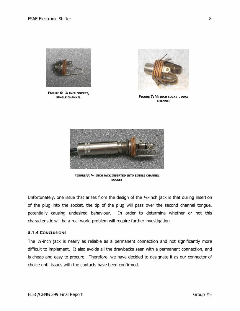
Unfortunately, one issue that arises from the design of the ¼-inch jack is that during insertion
of the plug into the socket, the tip of the plug will pass over the second channel tongue,
potentially causing undesired behaviour. In order to determine whether or not this
characteristic will be a real-world problem will require further investigation
5.1.4 CONCLUSIONS
The ¼-inch jack is nearly as reliable as a permanent connection and not significantly more
difficult to implement. It also avoids all the drawbacks seen with a permanent connection, and
is cheap and easy to procure. Therefore, we have decided to designate it as our connector of
choice until issues with the contacts have been confirmed.
FIGURE 6: ¼ INCH SOCKET, SINGLE CHANNEL FIGURE 7: ¼ INCH SOCKET, DUAL
CHANNEL
FIGURE 8: ¼ INCH JACK INSERTED INTO SINGLE CHANNEL
SOCKET

FSAE Electronic Shifter 9
ELEC/CENG 399 Final Report Group #5
5. 2 LINEAR ACTUATOR SELECTION AND TESTING
The linear actuator is a major component of this project. It connects directly to the
transmission shift mechanism and functions to replace the force generated by a human operator
moving a mechanical lever. In light of this, a significant amount of testing and research was
directed towards choosing an appropriate linear actuator.
5.2.1 FORCE MEASUREMENTS
In order to help us with selection of a linear actuator, we made a series of force measurements.
Both Shifting Up and Shifting Forces were measured:
TABLE 3: FORCE TABLE FOR SHIFTING DOWN
From To Shifting Down Force
(kilos)
6 5 11
5 4 11
4 3 10
3 2 11
2 1 11
TABLE 4: FORCE TABLE FOR SHIFTING UP
From To Shifting Up Force
(kilos)
1 2 10
2 3 11
3 4 10
4 5 10
5 6 10
As seen, the maximum force measured was 11kgF. Since we need a force that will always be
guaranteed to shift the transmission, 150% of 11kgF was used.

FSAE Electronic Shifter 10
ELEC/CENG 399 Final Report Group #5
Therefore, 16.5kgF (161.7N, or 581.6ozF) will be used as a minimum required force when
deciding on a linear actuator.
However, a more elegant solution may also exist.
5.2.2 PUSH/PULL SOLENOID
Though rather more expensive than the automotive lock actuator, a push-pull solenoid capable
of 960ozF (267N or 27.2kgF) is available for purchase on the McMaster-Carr website. Because
this device has not yet been tested, further discussion of its applicability to this project is
entirely hypothetical. Nonetheless, it meets the force requirements, runs on a 12V supply, and
draws only 6.67A at full power, which is easily delivered by the automotive power packs
installed on the vehicle. Possible issues may be length of stroke (too short to move gear
shifter) and physical size (too large to properly fit in constrained motor area).
5. 3 MICROCONTROLLER
Where the linear actuator is the muscle, the microcontroller is the brains. The microcontroller
chosen is the F28069 Piccolo controlSTICK from Texas Instruments. It features an easy
programming interface via USB, dedicated PWM outputs (if required for motor control), and pre-
written code for motor/solenoid control. The code is more-or-less ready for implementation,
with some minor modifications to customize it to our specific application.
The code file titled buttons.c can be found in the appendix of this report. The entire program is
spread over many files, but the interrupt initiation can be found in this particular snippet.
5. 4 SYSTEM INTEGRATION
The block diagram, as seen in Figure 9, outlines the control system of the electronic gear
shifter. As can be seen the 12 volt car battery will supply power to both the micro-controller
and the linear actuator. Starting at the steering wheel the driver can either shift up or shift
down using the paddle or button shifter which will send a signal through the audio jack to the
micro-controller. The micro-controller will then then a signal to the linear actuator which will
pull a lever coming out of the car transmission to either shift the transmission up or down.

FSAE Electronic Shifter 11
ELEC/CENG 399 Final Report Group #5
FIGURE 9: CONCEPTUAL BLOCK DIAGRAM SHOWING THE SIMPLE SYSTEM OPERATION

FSAE Electronic Shifter 12
ELEC/CENG 399 Final Report Group #5
6 – SUMMARY AND FUTURE WORK
In summary, having completed all the design process as well as modeled and confirming the
functionality of our design via simulation the electronic gear shifter is now ready to be built.
Although this is outside of the scope of the ELEC 399 course requirements, the design outlined
in the report could be taken by other members of the UVic Formula SAE team and then be built.
Furthermore, this project could be continued as an ELEC 499 project.
7 – BIBLIOGRAPHY
Amphenol Nexus Technologies. (n.d.). TP-120 Telephone Plug. Retrieved 11 05, 2012, from
http://nexinc.thomasnet.com/item/all-categories/telephone-plugs/tp-120
Drang. (2009, July 5). Poor man's cable release. Retrieved from And now it’s all this:
http://www.leancrew.com/all-this/2009/07/poor-mans-cable-release/
McMaster Carr. (n.d.). Solenoid Speciifed. Retrieved 10 28, 2012, from
http://www.mcmaster.com/#catalog/118/1019/=kco2h1
SAE International. (2012). Formula SAE Rules 2013. Retrieved 11 20, 2012, from SAE
International:
http://students.sae.org/competitions/formulaseries/rules/2013fsaerules.pdf
Surplus Center. (2012). 12VDC Power Door Lock Push/Pull Solenoid. Retrieved 10 12, 2012,
from .http://www.surpluscenter.com/item.asp?item=11-3346&catname=electric
Switchcraft. (n.d.). Jack Schematics. Retrieved from
http://www.switchcraft.com/Documents/Jack_Schematics.pdf

FSAE Electronic Shifter 13
ELEC/CENG 399 Final Report Group #5
8 – APPENDIX
Below is a sample of the code to be used in this project:
/* * buttons.c * * Created on: 2012-10-13 * Author: Lee Redstone */ #include "buttons.h" extern unsigned int upShift, downShift, neutralShift; void InitializeButtons() { EALLOW; GpioIntRegs.GPIOXINT1SEL.bit.GPIOSEL=2; //interrupt input GPIO02 XIntruptRegs.XINT1CR.bit.POLARITY=0; //See data sheet for
//XINTnCR for registers //(FALLING EDGE)
XIntruptRegs.XINT1CR.bit.ENABLE=1; //Active high PieCtrlRegs.PIEIER1.bit.INTx4=1; //P1 Int4 = XInt1 (enable
//PIE) PieVectTable.XINT1=&XINT1ISR; //This points to the
//interrupt routine. //Initialize second interrupt
GpioIntRegs.GPIOXINT2SEL.bit.GPIOSEL=3; //interrupt2 input = GPIO3 XIntruptRegs.XINT2CR.bit.POLARITY=0; //See data sheet for
//XINTnCR for registers //(FALLING EDGE)
XIntruptRegs.XINT2CR.bit.ENABLE=1; //Active high PieCtrlRegs.PIEIER1.bit.INTx5=1; //P1 Int5 = XInt2 (enable
//PIE) PieVectTable.XINT2=&XINT2ISR; //This points to
//the interrupt routine. //initialize third interrupt GpioIntRegs.GPIOXINT3SEL.bit.GPIOSEL=4; //interrupt3 input = GPIO4 XIntruptRegs.XINT3CR.bit.POLARITY=0; //See data sheet for
//XINTnCR for registers //(FALLING EDGE)
XIntruptRegs.XINT3CR.bit.ENABLE=1; //Active high PieCtrlRegs.PIEIER12.bit.INTx1=1; //P12 Int1 = XInt3 (enable
//PIE) PieVectTable.XINT3=&XINT3ISR; //This points to
//the interrupt routine.

FSAE Electronic Shifter 14
ELEC/CENG 399 Final Report Group #5
IER |= M_INT1; //First bit field for the CPU intr turns on all of the CPU1 ints IER |= M_INT12; //Enable XINT3 EDIS; //end EALLOW } interrupt void XINT1ISR() // Up Shift { EPwm1Regs.CMPA.half.CMPA = upShift; // CMPA? PieCtrlRegs.PIEACK.bit.ACK1 = 1; // Acknowledge interrupt in PIE } interrupt void XINT2ISR() // Down SHIFT { EPwm1Regs.CMPA.half.CMPA = downShift; // PieCtrlRegs.PIEACK.bit.ACK1 = 1; // Acknowledge interrupt in PIE } interrupt void XINT3ISR() // Neutral SHIFT { EPwm1Regs.CMPA.half.CMPA = neutralShift; PieCtrlRegs.PIEACK.bit.ACK12 = 1; // Acknowledge interrupt in PIE }

FSAE Electronic Shifter 15
ELEC/CENG 399 Final Report Group #5
Log book grade (25%): ______________
Report grade (75%): ______________
Total Grade (100%): _______________
Supervisor’s Comments:
______________________________________________________________________________
______________________________________________________________________________
______________________________________________________________________________
______________________________________________________________________________
______________________________________________________________________________
______________________________________________________________________________
______________________________________________________________________________
______________________________________________________________________________
______________________________________________________________________________
______________________________________________________________________________
______________________________________________________________________________
______________________________________________________________________________
_______________________ _____________________ ____________________
Supervisor’s name (Print) Signature Date
Notes for the supervisor:
1. Please return the marked hard copy to Prof. Tao Lu by Monday, December 10.
2. Attached additional pages for comments if necessary.