FRP International Vol. 14 No. 2 - IIFC · The AFGC guide have been presented on this occasion. 86...
27
FRP INTERNATIONAL the official newsletter of the International Institute for FRP in Construction IIFC has a new email address: [email protected] and a new website: WWW.IIFC.ORG Conference co‐chairs Emmanuel FERRIER, Karim BENZARTI, Jean‐François CARON INVITATION FROM CICE 2018 It is our great pleasure to remind you that new CICE conference will be in Paris. Paris will host the 9th CICE International Conference for the first time in Paris, France, from the 17th to 19th of July 2018. The conference would be held at the campus of Paris‐Est University, nearby Marne‐la‐Vallée, where are located two of the French leading research institutes in the field of construction and civil engineering, namely IFSTTAR (formerly LCPC) and Ecole des Ponts ParisTech. This convenient location offers both modern conference facilities adapted for hosting international scientific events, an easy access from Paris downtown by public transport (20‐30 min by express railway – RER A line), and a wide range of hotel accommodation due to the proximity to Disneyland Paris. The three institutes involved in the conference organization, i.e. IFSTTAR, Ecole des Ponts‐ParisTech and Université Lyon 1, have all been conducting researches on the applications of FRP composites in construction for nearly 20 years, and have gained an excellent reputation at the international level. The conference will be co‐chaired by three experienced scientists, Emmanuel FERRIER, Karim BENZARTI and Jean‐François CARON. Abstracts are expected to be submitted before 01 July but late abstracts may still be accepted. http://www.cice2018.com/fr Editor Tao Yu University of Wollongong, Australia IIFC Executive Committee President Jian‐Fei Chen Queen’s University Belfast, UK Senior Vice President Scott T. Smith Southern Cross University, Australia Vice President and Treasurer Amir Fam Queen’s University, Canada Vice Presidents Kent Harries University of Pittsburgh, USA Jian‐Guo Dai Hong Kong Polytechnic University, China Webmaster Peng Feng Tsinghua University, China Members‐at‐Large João R. Correia University of Lisboa, Portugal Dilum Fernando University of Queensland, Australia Doug Gremel Hughes Brothers Inc., USA Takashi Matsumoto Hokkaido University, Japan Conference Coordinators Guijun Xian (APFIS 2017) Harbin Institute of Technology, China Emmanuel Ferrier (CICE 2018) University Lyon I, France Secretary Raafat El‐Hacha University of Calgary, Canada Contact IIFC: [email protected] Table of Contents Invitation from CICE 2018 .......................................................................................................1 Activity Reports ............................................................................................................................2 IIFC on LinkedIn ...........................................................................................................................3 Best CICE 2016 Paper on Use of FRP in New Construction........................................4 IIFC Best PhD Thesis 2016: Extended Abstract ..............................................................9 Wet Lay‐Up Flax Composites for Strengthening RC Structures…… ..................... 14 FRP Plates Bonded on Concrete with Different FRP Anchor Configurations……21 Upcoming Events ...................................................................................................................... 24 IIFC Webinar Update ............................................................................................................... 25 Index of Journal of Composites for Construction, ASCE ........................................... 26 Vol. 14, No. 2, July 2017
Transcript of FRP International Vol. 14 No. 2 - IIFC · The AFGC guide have been presented on this occasion. 86...

FRPINTERNATIONALtheofficialnewsletteroftheInternationalInstituteforFRPinConstruction
IIFChasanewemailaddress:[email protected]
andanewwebsite:WWW.IIFC.ORG
Conferenceco‐chairsEmmanuelFERRIER,KarimBENZARTI,Jean‐FrançoisCARON
INVITATIONFROMCICE2018ItisourgreatpleasuretoremindyouthatnewCICEconferencewillbeinParis.Pariswillhostthe9thCICEInternationalConferenceforthefirsttimeinParis,France,fromthe17thto19thofJuly2018.
The conferencewould be held at the campus of Paris‐Est University, nearbyMarne‐la‐Vallée, where are located two of the French leading researchinstitutes in the field of construction and civil engineering, namely IFSTTAR(formerlyLCPC)andEcoledesPontsParisTech.Thisconvenientlocationoffersbothmodern conference facilities adapted for hosting international scientificevents,aneasyaccessfromParisdowntownbypublictransport(20‐30minbyexpressrailway–RERAline),andawiderangeofhotelaccommodationduetotheproximitytoDisneylandParis.
Thethreeinstitutesinvolvedintheconferenceorganization,i.e.IFSTTAR,Ecoledes Ponts‐ParisTech and Université Lyon 1, have all been conductingresearchesontheapplicationsofFRPcompositesinconstructionfornearly20years, andhavegainedanexcellent reputationat the international level.Theconference will be co‐chaired by three experienced scientists, EmmanuelFERRIER,KarimBENZARTIandJean‐FrançoisCARON.
Abstractsareexpected tobesubmittedbefore01 Julybut late abstractsmaystillbeaccepted.http://www.cice2018.com/fr
EditorTaoYuUniversityofWollongong,Australia
IIFCExecutiveCommitteePresidentJian‐FeiChenQueen’sUniversityBelfast,UK
SeniorVicePresidentScottT.SmithSouthernCrossUniversity,Australia
VicePresidentandTreasurerAmirFamQueen’sUniversity,Canada
VicePresidentsKentHarriesUniversityofPittsburgh,USA
Jian‐GuoDai
HongKongPolytechnicUniversity,China
WebmasterPengFengTsinghuaUniversity,China
Members‐at‐LargeJoãoR.CorreiaUniversityofLisboa,Portugal
DilumFernandoUniversityofQueensland,Australia
DougGremelHughesBrothersInc.,USA
TakashiMatsumotoHokkaidoUniversity,Japan
ConferenceCoordinatorsGuijunXian(APFIS2017)HarbinInstituteofTechnology,China
EmmanuelFerrier(CICE2018)UniversityLyonI,France
SecretaryRaafatEl‐HachaUniversityofCalgary,Canada
ContactIIFC:[email protected]
Table of Contents InvitationfromCICE2018.......................................................................................................1
ActivityReports............................................................................................................................2
IIFConLinkedIn...........................................................................................................................3
BestCICE2016PaperonUseofFRPinNewConstruction........................................4
IIFCBestPhDThesis2016:ExtendedAbstract..............................................................9
WetLay‐UpFlaxCompositesforStrengtheningRCStructures…….....................14
FRPPlatesBondedonConcretewithDifferentFRPAnchorConfigurations……21
UpcomingEvents......................................................................................................................24
IIFCWebinarUpdate...............................................................................................................25
IndexofJournalofCompositesforConstruction,ASCE...........................................26
Vol.14,No.2,July2017
FRPInternational•Vol.14No.2 2
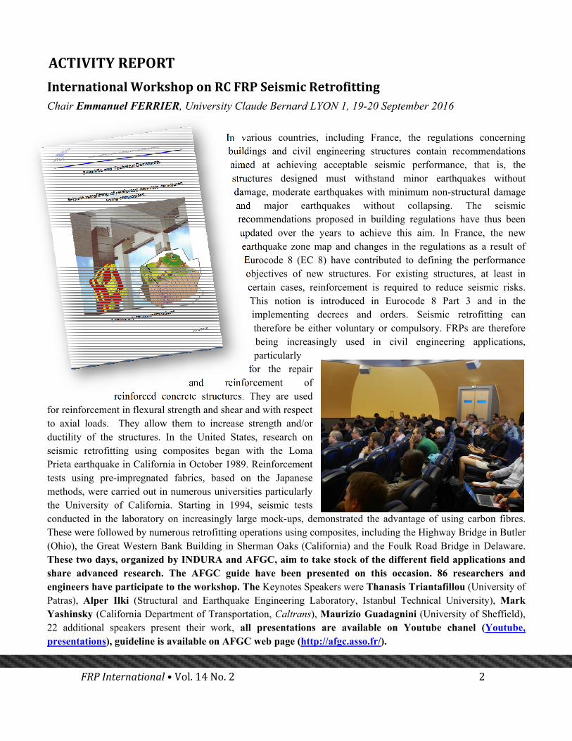
InternationalWorkshoponRCFRPSeismicRetrofittingChair Emmanuel FERRIER, University Claude Bernard LYON 1, 19-20 September 2016
In various countries, including France, the regulations concerning buildings and civil engineering structures contain recommendations aimed at achieving acceptable seismic performance, that is, the structures designed must withstand minor earthquakes without damage, moderate earthquakes with minimum non-structural damage and major earthquakes without collapsing. The seismic recommendations proposed in building regulations have thus been updated over the years to achieve this aim. In France, the new earthquake zone map and changes in the regulations as a result of Eurocode 8 (EC 8) have contributed to defining the performance objectives of new structures. For existing structures, at least in certain cases, reinforcement is required to reduce seismic risks. This notion is introduced in Eurocode 8 Part 3 and in the implementing decrees and orders. Seismic retrofitting can therefore be either voluntary or compulsory. FRPs are therefore being increasingly used in civil engineering applications, particularly
for the repair and reinforcement of
reinforced concrete structures. They are used for reinforcement in flexural strength and shear and with respect to axial loads. They allow them to increase strength and/or ductility of the structures. In the United States, research on seismic retrofitting using composites began with the Loma Prieta earthquake in California in October 1989. Reinforcement tests using pre-impregnated fabrics, based on the Japanese methods, were carried out in numerous universities particularly the University of California. Starting in 1994, seismic tests conducted in the laboratory on increasingly large mock-ups, demonstrated the advantage of using carbon fibres. These were followed by numerous retrofitting operations using composites, including the Highway Bridge in Butler (Ohio), the Great Western Bank Building in Sherman Oaks (California) and the Foulk Road Bridge in Delaware. These two days, organized by INDURA and AFGC, aim to take stock of the different field applications and share advanced research. The AFGC guide have been presented on this occasion. 86 researchers and engineers have participate to the workshop. The Keynotes Speakers were Thanasis Triantafillou (University of Patras), Alper Ilki (Structural and Earthquake Engineering Laboratory, Istanbul Technical University), Mark Yashinsky (California Department of Transportation, Caltrans), Maurizio Guadagnini (University of Sheffield), 22 additional speakers present their work, all presentations are available on Youtube chanel (Youtube, presentations), guideline is available on AFGC web page (http://afgc.asso.fr/).
ACTIVITYREPORT

FRPInternational•Vol.14No.2 3
VicRoadsFRPWorkshopMelbourne, Australia, 9-10 February 2017
VicRoads in conjunction with the International Centre for Composites in Infrastructure (ICCI) at the University of Wollongong hosted some of the
world’s leading researchers and innovators in the field of Fibre Reinforced Polymer (FRP) strengthening of bridges at the VicRoads FRP Workshop on 9-10 February 2017.
Over two very full days, a full VicRoads Kew theatrette comprising attendees from VicRoads, industry and academia, heard from expert presenters including founding members of the ICCI, Professor Jin Guang Teng (Hong Kong Polytechnic University), Professor Scott Smith (Southern Cross University), Dr. Tao Yu (University of Wollongong) and other leading researchers from ARC Research Hub for nanoscience based construction material manufacturing (ARC Nanocomm Hub) such as Professor Wenhui Duan (Director of ARC Nanocomm Hub), Dr. Kesi Sagoe-Crentsil (Deputy
Director of ARC Nanocomm Hub), Professor Riadh Al-Mahaidi (Swinburne University of Technology), Professor Xiao Ling Zhao (Monash University), Professor Priyan Mendis (Melbourne University), Associate Professor Yu Bai (Monash University), Dr. Lihai Zhang (Melbourne University) and Dr. Yew-Chin Koay (VicRoads).
The packed workshop agenda included presentations on developments in design methodologies for strengthening of bridges with FRP. The workshop was completed successfully and the feedback from the attendees is very positive.
IIFConLinkedIn
The IIFC Executive Committee from now will maintain an active LinkedIn pagehttp://www.linkedin.com/company/iifc, posting relevant information such as events,conferences,webinars, newsletters, awards and relevant projects, both from the academia andtheindustry.AllreadersareinvitedtofollowtheIIFCLinkedInpage.
ACTIVITYREPORT

FRPInternational•Vol.14No.2 4
The following paper was awarded Best Paper on use of FRP for new construction at the CICE 2016 held in Hong Kong in December 2016.
MODULAR CORELES FILAMENT WINDING FOR LIGHTWEIGHT SYSTEMS IN ARCHITECTURE J.Knippers1,V.Koslowski1,J.Solly1,T.Fildhuth2
1Institute for Building Structures and Structural Design (ITKE), University of Stuttgart, Germany. 2 Knippers Helbig Advanced Engineering, Stuttgart, Germany. Email: [email protected]
INTRODUCTION
Filament winding represents a cost effective and often used fabrication method for synclastic components such as pipes, vessels or aircraft fuselages. Typical filament winding techniques require the production of a positive mould onto which the fibres are later laid. The fabrication of this mould is an elaborate process and causes waste material. In addition the size of the core is usually limited by fabrication constraints. Thus, filament winding is often used for repetitive synclastic components of limited size and diameter. To overcome these drawbacks, a Coreless Winding process was conceived to avoid the production of a large positive core.
CORELESS WINDING FOR MODULAR STRUCTURES – ICD/ITKE RESEARCH PAVILION 13-14
Initially, the coreless winding process was used for large scale monocoque structures (La Magna et al. 2014, Reichert et al. 2014). In a second step the process is adapted to smaller individual components (Parascho et al 2015). The aim was the development of a winding technique for modular, double layered fiber composite structures, which reduces the required formwork to a minimum while maintaining a large degree of geometric freedom and leading to a strong and robust structural system. Through the development of computational design and simulation tools, both the robotic fabrication characteristics and
the structural requirements could be simultaneously integrated in the design process. A fabrication method was developed, which uses two collaborating 6-axis industrial robots to wind fibers between two custom-made steel frame effectors held by the robots. While the effectors define the edges of each component, the final geometry is emerging through the interaction of the subsequently laid fibers. The fibers are at first linearly tensioned between the two effector frames. The subsequently wound fibers lie on and tension each other which results in a reciprocal deformation.
This fiber–fiber interaction generates synclastic surfaces from initially straight deposited fiber connections. The order in which the resin impregnated fiber rovings are wound onto the effectors is decisive for this process and is described through the winding syntax. The specific sequence of fiber winding allows to control the layout of every individual fiber leading to a material driven design process. These reciprocities between material, form, structure and fabrication are defined through the winding syntax which therefore becomes an integral part of the computational design tool.
Figure 1 ICD/ITKE Research Pavilion 2013–14
The effectors are adjustable to various component geometries, leading to only one reconfigurable tool setup. Coreless filament winding does not only save substantial resources through the needlessness of individual molds, but in itself is a very material efficient fabrication process since there is no waste or cut-off of fiber mats.

FRPInternational•Vol.14No.2 5
Figure 2 Fabrication Set-up for ICD/ITKE Research Pavilion 2013-14
The specific robotic fabrication process includes the winding of 6 individual layers of glass and carbon fibers plus an optional layer for enclosure (Fig 4). A first glass fiber layer defines the elements geometry and serves as formwork for the subsequent carbon fiber layers. These carbon fiber layers act as structural reinforcement and are individually varied through the fibers anisotropic arrangement. A
simplified FE Analysis, in which the global structure is approximated as a continuous shell, gives the orientation of the stress tensors. They are transferred into fiber orientations which are finally corrected according to the constraints of fabrication (Fig 3). The generated winding syntax allows the automatic winding of the 6 fiber layers (Fig 4) including the structurally differentiated fiber layer 3.
Figure 3 FE Analysis of global force flows and their transfer into structural carbon fiber reinforcements
The woven components are joined using aluminium sleeves that are integrated into the edge of the fibrous structure. These sleeves are mounted onto the winding frame before the process begins. As the fibres are placed by the robot they are wrapped around the aluminium sleeves, becoming permanently bonded to them as the epoxy resin cures. The accurate location of the aluminium sleeves allows adjacent components to be linked by steel bolts passed through pairs of the sleeves and tightened simply by hand. Due to the depth of the
components the bending in the structure is converted into a push/pull tensile and compressive load. The bolts therefore carry tension and some limited shear.
In total 36 individual elements were fabricated. Each of them has an individual fiber layout which results in a material efficient load-bearing system. The biggest element has a 2.6 m diameter with a weight of only 24.1 kg. The research pavilion covers a total area of 50 m² and a volume of 122 m³ with a weight of 593 kg.

FRPInternational•Vol.14No.2 6
Figure 4 Winding Syntax for individual components
MODULAR FIBROUS SYSTEMS FOR ROOF STRUCTURES – ELYTRA FILAMENT PAVILION
While the aim of the ICD/ITKE Research Pavilion 2013-14 was to demonstrate the geometric and structural potential of the developed fabrication method the aim of the Elytra Filament Pavilion is to showcase how this approach could be used in a typical architectural application. The pavilion was installed in the John Madejski garden of the Viktoria and Albert Museum during summer 2016. It is based on the same modular concepts as described above but the fabrication process was further simplified for the use of one single robot only.
The roof was configured as a planar, slightly inclined canopy supported by seven columns. The canopy was a modular structure made up of initially 36 and finally 40 hexagonal roof components. 4 components were produced on site at specific public events. Each component was be covered by a polycarbonate sheet to provide rain coverage and drainage. The outer dimension of each component is identical: the depth is 40 cm and the diameter 2.40 m. After winding each
component is tempered in an oven for about six hours at 80 C°.
Figure 5 The Elytra Filament Pavilion at the Viktoria and Albert Museum in London, 2016
In this project the diameter of the central aperture as well as the reinforcement with carbon fibres along the edges and on the hyperbolic surface was differentiated according to the specific loading of the respective component. For analysis a simplified model was used as in ICD/ITKE Research Pavilion 2013-14: the woven mesh is represented as a surface and the woven edge connectors are idealised to lines (Fig 6). From material testing, the characteristic capacities of the wound fibre composites were

FRPInternational•Vol.14No.2 7
determined (Tensile Capacity ft,k = 4000MPa, Bending Capacity fb,k= 1330MPa). From these test a design strength of ft,d = 445MPa was chosen.
Wind loading has been considered in accordance with EN1991-1-4 General Actions – Wind Actions and the UK National Annex. The site in the central courtyard is generally sheltered as a central well within a larger bluff building structure. The wind loads applied were: Maximum uplift 0.72 kN/m2 along the edge, uplift on the remainder 0.46 kN/m2, max downforce 0.142 kN/m2.
Figure 6 Finite Element Model of the Canopy with all Columns
Two differently sized fibre composite columns were used to support the canopy. The three larger column heads around the fabrication core took majority of the horizontal wind loads (see Fig 6), while the smaller ones were connected to 10cm diameter steel tube and carried vertical forces mainly. The maximum tensile loading applied to any column is found to be 7kN. This requires an anchor to prevent uplift. A platypus anchor, common for temporary and semi-permanent structures in the UK, is used.
The maximum expected deflection of the structure under SLS loading combinations is found to be in the uplift case with maximum of 16mm uplift and 30mm downwards movement. Given the scale of the structure and the fact that these deformations will occur only in the worst case 1 in 50 year storm, this is considered to be acceptable. The structure is generally under a very low state of stress even in the most onerous loading condition due to the comparably small loads and large surface of structure across which these are distributed. At the junctions between elements and the support points for the polycarbonate covering some stress concentrations
are developed. The peak value is seen as 152MPa therefore this is still acceptable compared to the 445MPa limit.
In addition to structural analysis a variety of components and columns were tested (see Fig 7). The horizontal loading was increased until a bending moment as in FE Analysis of the global structure (Fig 6) was reached. In testing as well as in analysis buckling of the compression loaded edges proved to be the decisive failure mode. Deformation and stiffness properties were also measured. The results were used to adjust the stiffness properties of the global FE model shown in Fig 6.
Figure 7 Testing of components
The structural monitoring was achieved through optical fibre sensors that are integrated into the composite material (Gabler and Knippers 2014). This technology requires a light emitter and a reading station to be located close to the installation and permanently supplied with energy. The structural sensor fibres are equipped with BRAGG gratings that serve as elongation sensors. If the sensors are mounted to a structurally active surface strain is measured and the stress state in the material will be computed. If the sensor is detached from the load bearing structure, e.g. placed in a tube, it measures temperature. Six components are equipped with strain and temperature sensors prior to installation in Stuttgart. The sensing chains of the components will be connected via very small so called FP/APC plugs. Each component has 3 strain and 1 temperature sensor. The latter is needed for the temperature monitoring and to separate the measured elongations from thermal and mechanical loading.

FRPInternational•Vol.14No.2 8
Figure 8 Typical Fibre Optical Sensor Arrangement in one component (top)
and Fibre Optical Sensing Chains (bottom)
ACKNOWLEDGMENTS
Both projects are joint efforts of the ICD Institute for Computational Design (Prof. Achim Menges, Moritz Dörstelmann, Marshall Prado) and the ITKE Institute for Building Structures and Structural Design (Prof. Jan Knippers, Valentin Koslowski, James Solly, Stefana Parascho, Thiemo Fildhuth) at the University of Stuttgart. We want to thank many students, collaborators at the Universities of Stuttgart and Tübingen and sponsors who contributed to the projects and made them possible. Copyright of all images: ICD/ITKE University of Stuttgart.
REFERENCES
[1] La Magna, R., Waimer, F. and Knippers, J. (2014): Coreless Winding - A Novel Fabrication Approach for FRP Based Components In Building Construction. Proceedings of The 7th International Conference on FRP Composites in Civil Engineering, CICE 2014, Vancouver, Canada.
[2] Reichert, S., Schwinn, T., La Magna, R., Waimer, F., Knippers, J., Menges, A. (2014): Fibrous structures: an integrative approach to design computation, simulation and fabrication for lightweight, glass and carbon fibre composite structures in architecture based on biomimetic design principles. Comput. Aided Des. 52, 27–39
[3] Parascho, S., Knippers, J., Dörstelmann, M., Prado, M. and Menges, A.: Modular Fibrous Morphologies: Computational Design, Simulation and Fabrication of Differentiated Fibre Composite Building Components. In: P. Block et al. (eds.), Advances in Architectural Geometry 2014, DOI 10.1007/978-3-319-11418-7_3
[4] Gabler, M., Knippers, J.: Pultruded FRP Girder with Embedded Optical Sensor Network. Conference Proceedings CICE 2014 in Vancouver.

FRPInternational•Vol.14No.2 9
The following is an extended abstract of the PhD thesis receiving the IIFC Best Thesis Award at the CICE 2016 conference held in Hong Kong in December 2016.
DESIGN AND CHARACTERIZATION OF NATURAL FLAX FIBRE REINFORCED POLYMER TUBE ENCASED COIR FIBRE REINFORCED CONCRETE COMPOSITE STRUCTURE
Libo Yan (2014)
Advisor: Nawawi Chouw
The University of Auckland, New Zealand
https://researchspace.auckland.ac.nz/handle/2292/23949
Construction industry is responsible for the depletion of large amounts of non-renewable resources and for 30% of greenhouse gas emissions. With an increase of environmental concern, a sustainable construction industry is urgently needed. Reducing raw materials consumption by using renewable or waste materials is considered as a significant step to achieve a construction industry with sustainability. Natural fibres are renewable resources and readily available in many countries all over the world. Most importantly, the specific mechanical properties of natural fibres, i.e. flax (Figure 1), are comparable to those of glass fibres being used as reinforcement materials in fibre reinforced polymer (FRP) composites. The use of natural fibres, i.e. coir (Figure 2), as reinforcement within concrete structures will help to achieve a sustainable consumption pattern of building materials. Based on this fact, steel-free concrete structure using natural fibre reinforcements is developed, i.e., natural flax fibre reinforced polymer (FFRP) tube encased coir fibre reinforced concrete (CFRC) structure (FFRP-CFRC). This composite structure is composed of an outer FFRP tube and a CFRC core. In this composite structure, flax fibre is considered as the reinforcement of FRP tube because the comparable mechanical properties of flax to glass fibre. Coir fibre is considered as reinforcement of concrete because of its highest toughness amongst all natural fibres. In a FFRP-CFRC, the pre-fabricated FFRP tube serves as
permanent formwork for fresh concrete and also protects the concrete core from possible outer aggressive environments. In addition, as confinement of the concrete core, it increases concrete strength and ductility. Coir fibres within concrete are used to reduce concrete cracks and modify the failure mode of concrete. The composite structure becomes ductile because of coir fibre bridging effect. This PhD thesis provides a comprehensive understanding of design and characterization of this steel-free FFRP-CFRC composite structure for infrastructure application.
Figure 1 Flax plant
Figure 2 Coconut plant and coir fibres
In Chapter 2, a summary of recent developments of flax fibre and its composites has been provided. Firstly, the fibre structure, mechanical properties, cost, the effect of various parameters (i.e. relative humidity, various physical/chemical treatments, gauge length, fibre diameter, fibre location in a stem, oleaginous, mechanical defects such as kink bands) on tensile properties of flax fibre have been reviewed. Secondly, the effect of fibre configuration (i.e. in

FRPInternational•Vol.14No.2 10
forms of fabric, mat, yarn, roving and monofilament), manufacturing processes, fibre volume, and fibre/matrix interface parameters on the mechanical properties of flax fibre reinforced composites was discussed. The studies of life cycle assessment and durability investigation of flax fibre reinforced composites have also been reviewed. In addition, the mechanical properties and durability CFRC has been evaluated.
In Chapter 3, three different fabric reinforced polymer composites, i.e. flax, bamboo and linen, were fabricated using a vacuum bagging technique and their mechanical properties, i.e. tensile, flexural, compressive, vibration and in-plane shear, were studied. The results confirmed flax fabric to be used as reinforcement in the outer FRP tube. In addition, the failure mechanism of FFRP laminate, microstructure and fibre/epoxy matrix interfacial bond was analyzed using scanning electron microscopy (SEM) (Figure 3).
Figure 3 SEM micrograph of typical failure modes of plant-based natural flax fabric reinforced polymer composites. A. Fibre breakage, B. Fibre pull-out, C. brittle failure of polymer matrix and D. fibre debonding from polymer matrix.
In Chapter 4, FFRP tubes were fabricated using a hand lay-up process, the crashworthiness characteristics such as axial and lateral crushing of FFRP tubes with different geometries were experimentally investigated (Figure 4). The failure modes of the specimens were analyzed from photography. The parameters considered included number of FFRP layers, length-to-diameter ratios,
use of foam-filler and use of triggering. The energy absorption capability of these FFRP tubes were evaluated and compared with conventional metallic, i.e. aluminum and steel, and glass/carbon FRP (G/CFRP) composite tubes. These studies showed that FFRP tubes had comparable energy absorption capabilities of conventional metal or synthetic glass or carbon FRP composite tubes to be crushable energy absorbers for automotive engineering application. In addition, the flexural behaviour and vibration properties of large-scale FFRP composite tubes with different geometries are experimentally investigated.
Figure 4 Load-deformation history of hollow flax FRP tubular energy absorber in quasi-static axial
crushing
In Chapter 5, the axial compressive behavior of FFRP-CFRC of FFRP-PC composite columns as axial structural members was presented. The experimental results and analytical modelling of FFRP-CFRC and FFRP-PC composites were provided. Comparisons between experimental results and theoretical predictions based on the existing stress models for G/CFRP confined concrete were given. Based on the test results and the analysis, stress-strain model was proposed for FFRP-PC and FFRP-CFRC for practical design purpose. Factors influencing the strength and ductility of the composite such as: type of epoxy, tube end conditions, coir fibre content, coir fibre length and FFRP tube thickness, FFRP and concrete interfacial bond (e.g. FFRP-wrapped concrete, FFRP tube confined concrete and FFRP tube confined concrete with interlocking) were addressed. In addition, the confinement performance of FFRP-CFRC (Figure 5) and FFRP-PC were compared with that of synthetic

FRPInternational•Vol.14No.2 11
glass/carbon FRP confined concrete from the literature. It showed that the confinement effectiveness of FFRP-CFRC was close to or comparable to that of G/CFRP confined concrete, despite the tensile strength of FFRP composite, obtained from flat coupon tensile testing, being significant lower than that of G/CFRP (Figure 6). In addition, the addition of coir fibre can modify the failure of the concrete core from brittle to ductile (Figure 7 and Figure 8).
Figure 5 Axial compressive stress-strain curves of 2-layer and 4-layer FFRP-CFRC
Figure 6 Typical tensile stress-strain curves of flax FRP composites
Figure 7 Typical failure mode in compression
(a) flax FRP tube encased plain concrete (FFRP-PC) and (b) flax FRP tube encased coir fibre reinforced concrete (FFRP-CFRC)
Figure 8 Typical failure pattern of PC and CFRC cores after removed FFRP tube
In Chapter 6, the flexural behaviour of FFRP-PC and FFRP-CFRC composite beams as flexural structural members was introduced. The experimental results of FFRP-CFRC and FFRP-PC beams under four point bending were given. The flexural behaviour of FFRP-CFRC was compared with that of plain concrete (PC), CFRC and FFRP-PC specimens. The effect of coir inclusion and tube thickness on the ultimate load, deflection, energy absorption capacities, failure modes and ductility were addressed. The failure mode of CFRC core was further analyzed using photography and SEM study. The neutral axis depth of the composite beams was determined. A simplified analytical method based on linear elastic analysis and an assumption of Bernoulli’s theory was developed to predict the moment capacities of FFRP-PC and FFRP-CFRC beams. In addition, the slippage between FFRP tube and the concrete core was discussed and confirmed that slippage between FFRP tube and concrete core could be an issue which may compromise the structural performance of the composite structures. The flexural behaviour of FFRP-CFRC and FFRP-PC was compared with conventional steel reinforced concrete beams of the same dimensions. Small-scale concrete beams with external bonded flax FRP plates were also tested under flexure and indicated that FFRP has the potential of external strengthening materials. In addition, the results shown that the addition of coir fibre can modify the failure of the concrete core from brittle to ductile due to fibre bridge effect (Figure 9).

FRPInternational•Vol.14No.2 12
Figure 9 Failure modes in flexure
(a) 4-layer FFRP-PC, (b) 4-layer FFRP-CFRC, (c) CFRC core, (d) PC core and (e) coir fibre bridging of CFRC core
In Chapter 7, in the first part, a novel interlocked FFRP and CFRC interfacial profile was proposed and introduced to impede the slippage between the tube and the concrete core, which in turn increased the interfacial bond stress and composite action between the tube and the concrete core effectively. Push-out test was performed on normal and interlocked FFRP-CFRC cylinder to evaluate the effectiveness of this interlocking interface between FFRP tube and CFRC core. Then, the effect of interlocking on the axial compressive and flexural behaviour of FFRP-CFRC
composites was investigated. The effect of interlocking on slippage between the FFRP tube and the CFRC core was also analyzed and discussed. In the second part, the bond strength between FFRP panels and CFRC block with different profile parameters was experimentally investigated to have an optimized FFRP and CFRC interfacial profile. The experimental results were validated with the numerical simulation (Figure 10). The results will be used to develop a FFRP panel and CFRC overlay bridge deck in the future study.
Figure 10 Comparison in failure mode between experimental and numerical simulation of FRP plate - fibre reinforced concrete block specimen with perforations (i.e. 6 perforations and perforation thickness of 4-layer FRP laminate) on FRP plate after push-out bond test

FRPInternational•Vol.14No.2 13
In Chapter 8, this chapter included two parts. The first part introduced the hammer-induced vibration test on FFRP-PC and FFRP-CFRC beams in order to obtain the dynamic properties of composite beams in longitudinal, transverse and torsional vibration modes. The effects of coir inclusion and FFRP tube on these dynamic properties were discussed. The considered parameters were dynamic elasticity of modulus, Poisson’s ratio, damping ratio and natural frequency. The dynamic elasticity of modulus and Poisson’s ratio are compared with the values obtained from static axial compression test. The mechanism behind the increase in damping due to coconut fibres was discussed. The study showed that both FFRP tube and coir increased the damping ratio of the concrete significantly, thus reducing the impact of dynamic loading on the composite structure. Secondly, the seismic performance of FFRP-CFRC columns with and without interlocking were investigated using a shake table to simulate FFRP-CFRC columns as bridge piers (Figure 11). Snap back and harmonic tests were performed to identify fundamental frequencies and damping ratios. This study showed the potential of using this eco-friendly FFRP-CFRC as new structural materials with the capability of reducing seismic impact on structures. In addition, this study confirmed that the use of interlocking between FFRP tube and CFRC column by the incorporation of perforations on the tube inner surface can limit the seismic damage effectively (Figure 12).
Figure 11 A FFRP-CFRC column to simulate a bridge pier on a shake table
In Chapter 9, a summary of the investigations was given. The chapter also presented the general conclusions drawn from the work presented in this dissertation. Recommendations for design and characterization of FFRP-CFRC structures were given. Possible future research was outlined.
Figure 12 Failure modes of normal and interlocked FFRP-CFRC column after shake table test

FRPInternational•Vol.14No.2 14
FLAX/EPOXY COMPOSITES APPLIED BY WET LAY-UP FOR EBR RC STRUCTURES EXTERNAL STRENGTHENING
E.Ferrier,A.Hallonet,L.Michel
Université Claude Bernard Lyon 1, Laboratoire LMC², 82 Boulevard Niels Bohr, 69622 Villeurbanne Cedex, France.
Corresponding author: Emmanuel FERRIER ([email protected])
This study presents the mechanical characterization of wet lay-up flax/epoxy composites intended for the external strengthening of concrete structures. Composites have been manufactured using different weight and weaving of flax fabrics, and a bidirectional glass fabric. Tomography observations reveal a good impregnation of the fibers and porosity mainly located along the fiber bundles. The influences of the fabric’s choice and the number of series of specimen series of specimen on the properties were then examined through mechanical tensile and bond testing. Glass and flax composites present comparable tensile stress at failure.
1. Introduction
Growing ecological concerns and environmental requirements have led French and European industries to show an increasing interest in the use of natural fibers as reinforcement in composite. The substitution from synthetic fibers like glass to natural fibers as flax, hemp or jute presents technical and environmental advantages due to their renewable nature and low density [1-3]. In particular flax fibers (Linum usitatissimum) offer a combination of low density (1.5g/cm3), low cost and good specific properties, with tensile strength and stiffness reported to be as high as 1500 MPa and 90 GPa, respectively [4-7]. Many differences between flax and glass fibers prevent the direct transposition from the one technology to the other.
Figure 1 Flax fibers and fabrics
The poor compatibility between the hydrophilic fibers and hydrophobic polymers has been discussed in many researches [6-8], but is still difficult to improve without heavy chemical treatment. Moreover elementary flax fibers are made of concentric walls containing numerous cellulosic microfibrils, embedded in a pectic and hemicellulosic matrix. In the thickest wall (S2) microfibrils are oriented at 10° with the fiber axis. This complex
structure lead to a non-linear tensile behavior, described in the literature with a higher slope at small followed by softening of the curve into a second linear part [4,9].
2. Materials and method
In this paper the aim is to introduce and characterize a Flax Fiber Reinforced Polymer (FFRP) using the wet lay-up process that would suit as concrete external strengthening. The influences of the fabric choice and the number of series of specimen on the mechanical properties were then examined through mechanical tensile testing. The experimental data were compared to the predictions of Hook law of mixture as adapted by Coroller et al. [10].
2.1. Materials
The flax fabrics used in this study were cultivated and produced in France following the quality and traceability of ISO and NF XP T 25-501 norms specific to technical flax fibers. The flax fibers went through the four usual stages of preparation: pulling, retting, scutching, and heckling into ribbons. The ribbons have not been twisted in order to preserve the quality of the technical fibers. The quality of the final ribbon is standardized by mixing fibers from different productions years and flax varieties. The unidirectional fabrics are hold together by fine weft yarns that have been neglected in all further considerations due to the poor fabric cohesion on their direction. The bidirectional fabrics are woven in 3/3 twill offering balanced properties in both 0/90° directions. Two bi-components epoxy resins curing at

FRPInternational•Vol.14No.2 15
ambient temperature and commonly used in concrete strengthening have been selected. Their properties are displayed in Table 2. The epoxy basis and hardeners have been mixed at the specified ratio 33:17 for A and 7:3 for B.
Table 1. Characteristics of the used fabrics
Material ms(g/m²) E (GPa) σu (MPa) εu (%) Flax 350 Flax 600 32
550
1.7 Flax 220
Glass 300 70 1700 2.6
Table 2. Characteristics of the used resins
Resin ⍴ (kg.dm-3) E (GPa) σu (MPa) εu(%)
Epoxy A 1.06 2.0 35 1.2
Epoxy B 1.25 2.3 32.8 1.7
2.2. Preparation of the wet layup composites
Composite plates have been manufactured with each type of fabric, S350, S600, UD220 and G300, with increasing number of layers from 1 to 5. Fabric pieces of a length of 26 cm in the main directions and 11 cm width were impregnated with epoxy A matrix by hand and layered in the same orientation on waxed wooden plates with a layer epoxy B reproducing the layer enabling the composite to stick to a concrete surface. The composites are scraped with a trowel to eliminate excessive resin and the air bubbles as well as possible and are left to cure in atmospheric conditions at 20°C for 7 days.
2.3. Tensile test on the composites
The tensile specimens are cut out of the composite plates, 25 mm x 250 mm, using a circular saw with a water cooling system and left to dry 1 week before testing. Tensile tests on longitudinal direction were carried out following standardized static tension tests norm ISO 527-1 on a universal tensile testing machine ZWICK /1475. The tensile specimens were straightened at a cross-head speed of 1 mm/min until rupture of the specimen. Tensile force was determined through force sensor and longitudinal strain with 10 mm strain gauges (120 Ω) bonded to the composites specimens surface. For each type of fabric, composites have been manufactured with different number of series of specimen from 1 to 5, and at least 4 specimens have been tested. The ultimate strain and tensile modulus were calculated both as specifies in the norm using the gross-laminated area (real properties) and the net fiber area (net properties) as introduced by the American
Concrete Institute [11] for reinforcement composites. The real properties are calculated using the total cross-sectional area of the cured composite. The net properties are calculated using the thickness of the fibers only, neglecting the polymer thickness, as a mean to limit the effect of significant composite thickness variation. The tensile stress per composites width was also calculated (ξu) in kN.cm-1. For the flax FRP the stress-strain curves present a higher slope at small deformations as has been previously stated by many with flax fibers [6, 12] have associated this phenomenon by the reorientation of flax micro-fibrils. Two modules were therefore calculated for the flax composites following Bensadoun et al. [13] recommendations, a first E1 between 0-0.1% strain, and a second E2 between 0.3-0.5% strain. The module for the glass composite was calculated following the ISO 527-1 norm, between 0.05-0.25% strain.
2.4. Double lap shear test description
Although single lap shear tests are more widely exploited in literature, the interface can rapidly be subjected to normal and bending stresses in addition to the shear stresses. This artefact can influence the failure mode and induce earlier failure (e.g. Chajes et al. [14]). In contrast, double lap shear tests appear to have more consistent and comparable responses. The standard double lap shear test proposed by the Japanese Concrete Institute and modified by Ferrier [15] was retained for this investigation. This test configuration has been operating for many studies in the laboratory in recent years (e.g. Michel [16]), which offers possibilities of essential comparisons. The double lap shear test configuration illustrated in Figure 1 consists of two concrete blocks internally reinforced by a threaded rod and bonded by two parallel bonded FRP strips.
Figure 2 Double lap shear test configuration
A tensile load is applied to the concrete blocks inducing the transfer of shear stress to the adhesive joint without any flexure until failure of the system. The tests were performed on a universal tensile

FRPInternational•Vol.14No.2 16
machine Zwick 1475 at a cross-head speed of 1 mm/min until failure of the specimens at room temperature (20°C).
3. Results and discussion
3.1. Microstructures and volumetric ratio of fibres
The illustrations in Figure 1 show tomography cross-sections of the flax UD220 (x3) and glass G300 (x3) composites. The glass fibres appear more distinctly from the matrix then the flax fibres due to their chemical nature. The two different epoxy resins are distinguished by the presence in resin B of mineral particles, which bring the resin its viscosity and appear in white on the pictures. The limit between the two resins is not very clear, which confirms their good compatibility. The general aspect of the samples as quite heterogeneous with the three layers of fabrics easily identifiable and separated by resin rich layers. However the flax bundles are well impregnated at heart. Porosities have varying sizes, up to a few millimetres and are mainly located along the fibre bundles or in the resin B. Even though glass and flax composites were manufactured in the exact same way, flax composites present more resin rich regions and fibres bundles appear swollen, which is not the case for the glass composites. The swelling of the flax fibres induces a higher uptake of resin and thicker composites as was previously stated by Ngyen et al. [19].
Figure 3 Tomography pictures of UD220 and G300, and post-exploitation to determine the porosity ratio
The porosity is mainly concentrated along and inside of the fiber bundles as was evidenced by the tomography observations. The composites made with the bidirectional fabrics have overall higher fiber ratio than those with the unidirectional fabric as
logical consequence of denser mesh in bidirectional fabrics.
3.2. Tensile properties of the composites
Tensile failure of the specimens occurs cohesively without significant loosening of the fibers. Figure 2 shows the tensile behavior of the different composites with increasing number of series of specimen. The curves are slightly dispersed, what could be a sign for some heterogeneity in the material, so that for readability reasons only a single average curve is shown for each number of series of specimen. All the stress-strain curves of the flax composites present a higher slope at small deformations until a strain of ~0.15% as has been previously stated by many with flax fibers, both unidirectional and random mat of flax [4-7]. The experimental values of the tensile properties are summarized in Table 3. The mechanical properties of the flax composites vary with a standard deviation of 15% on the stress and the tensile stress, and 20% on the modules. For all composites the tensile stress increases linearly with the number of series of specimen (Figure 5a). Although the constraints and modules calculated for the glass composites are higher than for flax composites, tensile efforts are similar. Thus the maximum effort flax and glass composites can take up are comparable. Similarly, the ‘real’ glass composites’ modules have comparable values to the ‘real’ E1 modules of flax composites. The superior mechanical properties of the composite glass would therefore mainly be due to the difference in thickness of the glass fabric, denser than the flax fibers at equal weight. According to various publications composite mechanical properties would be proportional to the percentage of fiber [2,15]. The unidirectional flax composites present higher properties for similar fiber contents than the bidirectional composites, even by considering only the content of the fiber in the main direction. Bidirectional composites are nonetheless interesting to consider as reinforcement materials, as the applied stress on structures might not always be strictly in the fibers main direction, and they are easier to handle during the onsite manufacturing.
Flax composites present average properties with an initial modulus E1 = 20 GPa, a second modulus E2 =

FRPInternational•Vol.14No.2 17
12.5 GPa and an average stress at break of σu,flax = 160 MPa with average deviations of 10%. The glass composite have higher net properties of E = 30 MPa and σu,glass = 400 MPa with average deviations of 5%.
The net calculation method actually allows considering constant values of the flax composites’ mechanical properties, which is a crucial element for structural reinforcement design calculations.
(a) Composite UD220(b) Composite S600
(c) Composite S350(d) Composite G300
Figure 4 Evolution of the “real” stress-strain curves of the composites with the number of series of specimen
(a) Stress per width with the series of specimen number(b) Fiber volumetric ratio with the number of series of specimen
Figure 5 Evolution of the “real” stress-strain curves of the composites with the number of series of specimen
3.3. Mechanical prediction model
According to the law of mixtures the average properties of the composites can be calculated knowing the properties of the individual constituents. The tensile modulus E can then be expressed as a
function of the volumetric fibers ratio of the fibers Vf
following Eq. 1 :
∙ 1 ∙ (Eq 1)
With Em, Ef and Eth respectively the tensile modulus of the matrix, the fibers and the theoretical tensile

FRPInternational•Vol.14No.2 18
modulus of the composite. The stress at failure σu was calculated in two ways; first by supposing that the failure of the matrix would induce the failure of the composite (Eq. 2), and secondly by supposing that all components worked cohesively following a simple mixture rule (Eq. 3).
∙ 1 ∙ , ∙ ∙
(Eq 2)
∙ 1 ′ ∙ ∙
(Eq 3)
The matrix’s properties were calculated as the weighted average of the two resins and were found to be quite constant for all composite with Em= 2.1 GPa and σm = 34 MPa. The estimated tensile modulus and strength from the mixture law are shown in Table 3.
Table 3 Prediction of tensile modulus and strength at break from mixture rules and calculated efficiency factors for the stress at failure
Com
posi
te
Ser
ies
of
spec
imen
Vf (
%)
Mod
ulus
E
2,ex
p (G
Pa)
Mod
ulus
Eth
(G
Pa)
Str
ess
σ u,e
xp (M
Pa)
Str
ess
σ u
,th (M
Pa)
Eff
icie
ncy
fact
or k
Str
ess
σ'
u,th
(MP
a)
Eff
icie
ncy
fact
or k
’
S350 1 8 3.2 ± 0.2 3.2 35 ± 3 51 0.21 53 0.20 2 16 3.9 ± 0.1 4.2 46 ± 4 68 0.46 71 0.44 3 18 4.2 ± 0.3 4.5 56 ± 7 72 0.65 75 0.62
S600
1 9 3.2 ± 0.4 3.3 31 ± 3 53 0.06 54 0.06 2 19 4.3 ± 1.0 4.6 48 ± 7 75 0.45 78 0.42 3 25 5.2 ± 0.5 5.4 62 ± 4 87 0.61 91 0.58 4 28 5.6 ± 0.5 5.8 68 ± 3 95 0.63 99 0.60
UD220
1 11 4.7 ± 0.5 5.3 65 ± 6 86 0.63 90 0.59 2 14 6.1 ± 0.6 6.2 75 ± 22 101 0.64 105 0.61 3 15 6.0 ± 0.4 6.5 83 ± 20 106 0.71 111 0.67 4 15 6.1 ± 0.6 6.5 81 ± 15 105 0.69 110 0.65 5 17 6.9 ± 0.6 7.1 90 ± 13 115 0.72 120 0.68
G300
1 21 9.0 ± 0.5 9.0 93 ± 7 145 0.56 142 0.37 2 22 10.0 ± 0.6 10.3 115 ± 28 166 0.64 162 0.43 3 29 11.9 ± 0.8 11.6 170 ± 13 187 0.89 183 0.60 4 33 12.1 ± 0.2 12.9 200 ± 10 209 0.95 203 0.64
For the flax composites the modulus values were compared to experimental real modulus E2. For composites reinforced with bidirectional fabrics, only half of the fibers in the longitudinal direction part in the effort and fiber ratios were accordingly adjusted in the calculations. The estimated modulus Eth show good correlation with experimental values especially considering the average standard deviations. The estimation the strength at break σu however led to a wide overestimation of 30% to 70%, with or without considering the failure of the matrix as a limiting factor. Coroller et al. [10] had similar observations and therefore proposed to introduce an efficiency factor k, depending mostly on the fibers individualization state. The efficiency factors increase with the number of series of specimen from up to +100% from 1 to 4 series of specimen. For the glass composites the efficiency factor k is higher by
50% than the factor k’ considering the failure of the matrix as a limiting factor. This difference can be explained by the mode of failure of the composites. Indeed for composites flax fibers, failure occurs cohesively. The fibers break at the same time as the matrix. Accordingly the law of mixtures by considering the matrix as limiting element leads to greater overestimation of the breaking stress of the composite glass fiber. The efficiency factor k’ not only conveys the effectiveness of the fibers’ individualization, but also their working ratio at failure. According to this hypothesis the difference between the factors k and k’ suggest that the flax fibers work to about 95% of their capacity, while the glass fibers only work to 67%.
3.4 Average ultimate shear strength of the shear test

FRPInternational•Vol.14No.2 19
The experimental data of the tested specimens is summarized in Table 4. The three series present similar data results. All specimens exhibit a shear failure of the concrete. For the specimens F600-x3 the cracking of the concrete was followed by a detachment of the remaining composite, while for the F220-x4 and G300-x4 the failure happened with a rupture of the composite.
Table 4 Experimental results of the double lap shear tests
Com
posi
te
wid
th,
b f (
mm
)
Len
gth
anch
orag
e, L
anch
(m
m)
Spec
imen
Ult
imat
e lo
ad P
u
exp
(kN
)
Ult
imat
e sh
ear
stre
ngth
τ adh
,u (
MPa
)
Ult
imat
e sh
ear
stra
in γ
adh,
u (%
)
Flax
T
will
600
g/m
² (x3
)
60
1 31.0 1.22 1.34
2 30.7 1.20 1.13
210 3 30.8 1.21 1.74
4 31.2 1.23 1.60
Av. 30.9 ±0.22
1.22 ±0.02 1.45
±0.31
Fla
x U
D 2
20 g
/m²
(x4)
1 29.3 1.16 -
70 200 2 31.2 1.24 -
3 35.4 1.35 1.22
Av. 32.0 ±3.3
1.22 ±0.13
1.22
Gla
ss 2
D 3
00
g/m
² (x4
)
1 31.4 1.21 1.28
70 200 2 34.0 1.24 1.64
Av.
32.6 ±1.6
1.22 ±0.2
1.46 ±0.18
The concrete is therefore the weak element of the system. The ultimate shear stress depends accordingly almost entirely on the concretes mechanical properties. Samples reinforced with flax and glass fabrics exhibit both an average ultimate shear strength of 1.22 MPa; and an average strain at failure of 1.3%. A piece of concrete near the loaded end is driven out at failure with a depth of 4 to 7 cm and a length of 3 to 8 cm for the F600-x3, and with a depth of 2 to 3 cm and a length of 3 to 4 cm for F220-x4. Notable differences between the two types of flax
reinforcements are (1) the mechanical properties, tensile strength and modulus, slightly higher for F600-x3 than for F220-x4 and (2) the flax F600-x3 is bidirectional as opposed to the unidirectional F220-x4. Fibers aligned in the direction perpendicular to the force applied could provide better adhesion to the concrete substrate and, could be less prone to delamination and thus explain the drive to break a piece of concrete more consistent with the UD fabric.
4. Conclusion
Composites plates were manufactures following the wet lay-up process with increasing number of fabric layers from 1 to 5 with different unidirectional and bidirectional flax fabrics and a glass fabric. Flax composites presented a slightly higher porosity ratio of 5% instead of 3% for the glass composite, mainly along the fiber bundles. The tensile stresses at break of both composites are comparable and increase linearly with the number of series of specimen, showing cohesive working of the layers. The ‘net’ tensile stay constant with the number of series of specimen for the flax composites ( E1 = 20 GPa, E2 = 12.5 GPa, σu,flax = 160 MPa) as well as the glass composite (E = 30 MPa, σu,glass = 400 MPa) enabling design calculations. The ‘real’ properties show a linear increase with the volumetric fiber ratio Vf. and were compared to mixture law prediction calculations. For the flax composites the assumption that the tensile failure of the matrix induces the failure of the composite appears to be verified. For the glass composites however, fibers are first laid bare through cracking of the matrix and still alone work before failure of the composite, so that the flax fibers would work to about 95% of their capacity, while the glass fibers only work to 67%. The resulting mechanical properties of the flax composites open the possibility to use flax for the external reinforcement of concrete structures in a wet lay-up process. The double lap shear tests induce a failure in the concrete for all specimens, thus showing a good adhesion between the composite and with the concrete substrate. Flax composites show the same interface behavior than glass fiber reinforcement.

FRPInternational•Vol.14No.2 20
5. Acknowledgments
The authors would like to acknowledge the financial support of the project FIABILIN and the Ministry of Research and Innovating Technologies. The authors also want to thank the society DEHONDT for providing the flax fabrics; as well as the society FREYSSINET for the resins.
6. References
[1] Le Duigou A, Kervoelen A, Le Grand A, Nardin M, Baley C. Interfacial properties of flax fibre–epoxy resin systems: Existence of a complex interphase. Composites Science and Technology 2014;100:152–157.
[2] Summerscales J, Dissanayake NPJ, Virk AS, Hall W. A review of bast fibres and their composites. Part 1 – Fibres as reinforcements. Compo Part A: App Sc and Manuf 2010;41(10):1329-1335.
[3] Shah DU, Schubel PJ, Clifford MJ. Can flax replace E-glass in structural composites? A small wind turbine blade case study. Comp Part B 2013;52:172–181.
[4] Charlet K, Eve S, Jernot JP, Gomina M, Breard J. Tensile deformation of a flax fibre. Proc Eng 2009;1(1):233–6.
[5] Dittenber DB, GangaRao HVS. Critical review of recent publications on use of natural composites in infrastructure. Comp Part A 2012;43:1419-29.
[6] Baley C, Le Duigou A, Bourmaud A, Davies P. Influence of drying on the mechanical behaviour of flax fibres and their unidirectional composites. Comp Part A – App Sc 2012;43(8):1226-33.
[7] Yan L., Chouw N, Jayaraman K.. Flax fibre and its composites – A review. Comp Part B: Eng 2014;56:296–317.
[8] Azwa ZN, Yousif BF, Manalo AC, Karunasena W. A review on the degradability of polymeric composites based on natural fibres. Materials & Design 2013;47:424-442.
[9] Baley C. Fibres naturelles de renfort pour matériaux composites. Techniques de l’Ingénieur. Réf : AM5130, Publié :10 janvier 2013.
[10] Coroller G, Lefeuvre A, Le Duigou A, Bourmaud A, Ausias G. Effect of flax individualization on tensile failure of flax/epoxy unidirectional composite. Comp Part A 2013;51:62-70.
[11] Guide for the Design and Construction of Externally Bonded FRP Systems for Strengthening Concrete Structures. ACI Committee 440.2R-08, American Concrete Institute, Michigan (2008).
[12] Poilâne C, Cherif ZE, Richard F, Vivet A, Ben Doudou B. Polymer reinforced by flax fibers as a viscoelastoplastic material. Comp Struc 2014;112:100-112.
[13] Bensadoun F, Vallons KAM, Lessard LB, Verpoest I, Van Vuure AW. Residual properties and damage evolution of flax-epoxy composites subjected to fatigue loading. In: Proceedings of ICCM-20 Conference. Copenhagen, July, 2015.
[14] Chajes MJ, Finch WWJ, Januszka TF, Thonson TAJ. Bond and force transfer of composite material plates bonded to concrete. ACI Struct J 1996;93(2):295–303.
[15] Ferrier E, Quiertant M, Benzarti K, Hamelin P. Influence of the properties of externally bonded CFRP on the shear behavior of concrete/composite adhesive joints. Composites Part B 2010;41:354-362.
[16] Ferrier E, Michel L, Jurkiewiez B, Hamelin P. Creep behavior of adhesives used for external FRP strengthening of RC structures. Construction and Building Materials 2011;25:461-467.
[17] Yuan H, Teng JG, Seracino R, Wu ZS, Yao J. Full-range behavior of FRP-to-concrete bonded joints. Engineering Structures 2004;26:553–565.
[18] Nguyen VH, Deleglise-Lagardere M, Park CH. Resin impregnation of flax fiber preform: effect of liquid sorption and fiber swell. In: Proceeding of JNC19 Conference. Lyon, July, 2015.

FRPInternational•Vol.14No.2 21
FRP PLATES BONDED ON CONCRETE WITH DIFFERENT FRP ANCHOR CONFIGURATIONS TogayOzbakkaloglu,AliakbarGholampour,andChengfengFang
The University of Adelaide, SA, Australia
Introduction
Fiber-reinforced polymer (FRP) composites are recognized for their high tensile strength, strength-to-weight ratio, corrosion resistance, easy installation, and versatility. A large number of studies conducted to date (e.g. [1-3]) have shown the significant increases in the load capacities of concrete members through FRP strengthening. However, due to high interfacial shear and normal stresses at the FRP-to-concrete interface, debonding failure modes such as plate end debonding, concrete cover separation, and intermediate crack-induced debonding were frequently reported in previous studies [1-5]. Such debonding failure results in the premature failure of the FRP plate strengthening system before it develops its full strength. The use of anchorage has emerged as one of the most promising techniques for delaying or preventing interfacial debonding failure in concrete members retrofitted with externally bonded FRP laminates [6]. It was shown in previous studies that the use of FRP spike anchors results in increases in both the bond strength at the FRP-concrete interface and axial strain in the FRP plate, allowing a more efficient use of the FRP material [5]. A review of the literature has shown that the effect of anchor configuration on the behavior of FRP plates with multiple anchors has not been sufficiently studied. This study was aimed at addressing this gap.
Test Program
Materials and test specimens
Rectangular concrete blocks (350 × 150 × 250 mm) were prepared using a concrete with an average compressive strength of 49.6 MPa for the single shear tests of FRP-anchored plates. Carbon FRP plates with a width of 100 mm, a length of 500 mm were prepared using a manual wet layup process by adhering four layers of carbon fiber sheets with a
thickness of 0.167 mm/layer together, which resulted in a plate thickness of 2.6 mm. Aluminum tabs measuring 140 mm long and 100 mm wide were bonded on the edge of the FRP plate to ensure that load was applied to the plate uniformly and without damage to the composite (Fig. 1(a)). The required holes for anchored specimens were drilled by a drill press on the FRP plate and concrete block (Fig. 1(b)). A 270-mm long section of the plate was bonded on the concrete block, whereas a 40-mm long section of the plate near the edge of the concrete block was left unbonded to prevent concrete wedge failure that could result due to high stress concentrations [7].
Figure 1 (a) FRP plates with aluminum tabs, (b) drilling of anchor holes on FRP plates, (c) FRP
anchors
The same unidirectional carbon fiber sheets used in FRP plates were used to manufacture the FRP anchors (Fig. 1(c)). Anchors with two different embedment depths (i.e. 40 mm and 60 mm) were considered. Figure 2 shows the FRP plates and anchors after their installation on concrete blocks.
Figure 2 FRP plates and anchors installed on concrete blocks
Aluminumtab
(a)
(b) (c)

FRPInternational•Vol.14No.2 22
Figure 3 shows some of the different anchor arrangements used in this study.
(a)
(b)
(c)
Figure 3 Anchor arrangements: (a) single-anchor, (b) double-anchor with a longitudinal arrangement pattern, (c) double-anchor with a transverse arrangement pattern [8]
Instrumentation and testing procedures
As shown in Fig. 4, the single shear tests were conducted using a universal testing machine at a loading rate of 0.5 mm/min. A single linear variable differential transformer (LVDT) with a 50 mm displacement capacity was used to measure the slip between the FRP plate and concrete.
Figure 4 Test setup for direct shear tests
Test Observations
Failure modes
Figure 5 shows the failure modes of unanchored, single-anchor, double-anchor, and quadruple-anchor specimens. As can be seen in Fig. 5(a), the failure
mode of unanchored specimens was the plate debonding at the FRP-concrete interface. The failure of anchored specimens initiated by the delamination of the FRP plate, which was followed by a secondary stage involving anchor pullout, anchor rupture, or plate splitting, until the plate completely debonded from the concrete surface.
(a)
(b)
(c)
(d)
(e)
Figure 5: Failure modes of (a) unanchored, (b) single-anchor, (c and d) double-anchor, and (e) quadruple-anchor specimens
Peak load and displacement
The comparison of the results of unanchored and single-anchor specimens showed that initial peak load, corresponding slip, and maximum longitudinal strain of the FRP plate increased significantly in the presence of an FRP anchor. Results of the single-anchor specimens indicated that increasing anchor embedment depth from 40 mm to 60 mm resulted in a slight increase in the initial peak load and a significant increase in the second peak load and maximum longitudinal strain. The initial and second peak load, corresponding slips, and maximum longitudinal strain of the single-anchor specimens decreased significantly with an increase in the distance between the anchor and loaded end from 45 mm to 225 mm. This is attributed to the reduced contribution of the anchor toward the load resistance
Aluminium tab
Specimen
Jaws
Metal plates holding specimen
in place

FRPInternational•Vol.14No.2 23
of the plate with an increase in the distance between the anchor and loaded end.
In specimens with a double longitudinal-anchor configuration, an increase in the distance between the leading anchor and loaded end from 45 mm to 135 mm, while maintaining the distance between the lead and second anchor, led to a decrease in the initial and second peak loads, corresponding slips, and maximum longitudinal strain. In double transverse-anchor series, significant decreases occurred in the initial and second peak load and maximum longitudinal strain with an increase in the distance between the anchors and loaded end from 45 mm to 225 mm. In addition, plates with a longitudinal-anchor configuration developed a higher maximum longitudinal strain than those with a transverse-anchor configuration.
Comparison of quadruple-anchor specimens showed that an increase in the distance between the leading anchors and loaded end from 45 mm to 135 mm resulted in a decrease in the initial peak load, but an increase in the second peak load and maximum longitudinal strain of the FRP plate.
Conclusions
This study has presented new information on the influence of FRP anchor configuration on the behavior of FRP plates externally bonded on concrete. Single shear tests were conducted on specimens with carbon FRP anchors in different configurations. The results show that the initial and second peak load, and maximum longitudinal strain of an FRP plate system increase in the presence of FRP anchor and with an increase in the number and embedment depth of the anchor. Moreover, the peak loads and corresponding slips, and the maximum plate longitudinal strain of single- and double transverse-anchor series tend to decrease with an increase in the distance between the anchor(s) and loaded end. An increase in the distance between the leading anchor and loaded end leads to similar decreases in specimens with double longitudinal anchors. In specimens with quadruple anchors, an increase in the distance between the leading anchors and loaded end results in a decrease in the initial peak
load and an increase in the second peak load. The findings of this study, as discussed in detail in Ref. [8], provide important insights into the behavior of anchored FRP plates and should inform the development of future design guidelines.
Acknowledgements
The authors acknowledge the financial support by the University of Adelaide through a Research Excellence Grant awarded to the first author. The authors thank Messrs. Jollands, Gorny, Maynes, and O'Callaghan for undertaking the tests reported in this paper as part of their Honour’s research project. This research is part of an ongoing program at the University of Adelaide on the development of FRP-concrete composite structural systems.
References
[1] Chen, J. F., Teng, J. G. (2003). Shear Capacity of Fiber-Reinforced Polymer-Strengthened Reinforced Concrete Beams: Fiber Reinforced Polymer Rupture. Journal of Structural Engineering, 129(5), 615-625. [2] Ameli, M., Ronagh, H. R., Dux, P. F. (2007). Behavior of FRP strengthened reinforced concrete beams under torsion. Journal of Composites for Construction, 11(2), 192-200. [3] Baggio, D., Soudki, K., Noël, M. (2014). Strengthening of shear critical RC beams with various FRP systems. Construction and Building Materials, 66, 634-644. [4] Teng, J. G., Smith, S. T. Yao, J., Chen, J. F. (2003). Intermediate crack-induced debonding in RC beams and slabs. Construction and Building Materials, 17,447-462. [5] Kalfat, R., Al-Mahaidi, M., Smith, S. T. (2013). Anchorage devices used to improve the performance of reinforced concrete beams retrofitted with FRP composites: state-of-the-art review. Journal of Composites for Construction, 17(1), 14-33. [6] Ozbakkaloglu, T., Saatcioglu, M. (2009). Tensile behavior of FRP anchors in concrete. Journal of Composites for Construction, 13, 82-92. [7] Zhang, H. W., Smith, S. T. (2012). FRP-to-concrete joint assemblages anchored with multiple FRP anchors. Composite Structures, 94(2), 403-414. [8] Ozbakkaloglu, T., Fang, C., Gholampour, A. (2017). Influence of FRP anchor configuration on the behavior of FRP plates externally bonded on concrete members. Engineering Structures, 133, 133-150

FRPInternational•Vol.14No.2 24
UpcomingConferencesandMeetings
6thAsia‐PacificConferenceonFRPinStructures
The6thAsia‐PacificConferenceonFRPinStructures(APFIS2017),jointlyorganizedbyMCCSingaporeandFRPapplicationcommitteeofCCES(ChineseCivilEngineeringSociety)underthepatronageofIIFCwillbeheldon19‐21July2017inSingapore.
International Symposium for Emerging Researchers in Composites for Infrastructure(ISERCI)andInternationalSummerSchoolonCompositesinInfrastructure(ISSCI)
TheinauguralInternationalSymposiumforEmergingResearchersinCompositesforInfrastructure(ISERCI)andthesecondInternationalSummerSchoolonCompositesinInfrastructure(ISSCI)willbehostedbytheInternationalCentreforCompositesinInfrastructure(ICCI)attheUniversityofWollongongonJuly10‐14,2017.
SMAR2017,thefourthInternationalConferenceonSmartMonitoring,AssessmentandRehabilitationofCivilStructures, is organized by Empa and ITÜ and will be sponsored jointly by the International Society forStructural Health Monitoring of Intelligent Infrastructure (ISHMII), the International Institute of FRP inConstruction(IIFC)andRilem.

FRPInternational•Vol.14No.2 25
IIFCWebinarUpdate
IIFC is very pleased to inform you that after few months of break IIFC webinars have been back in June with 3 webinars:
‐ João Ramôa Correia: Fire Behaviour of FRP material and structure : 08 of June evening GMT time, 03:00 Lisbon time,
‐ Ferrier Emmanuel: EB strengthening of RC structures using natural Flax FRP : 22 of June, evening 03:00 Paris time;
‐ Scott T. Smith : FRP Timber Strengthening : 27 of June in the morning GMT time, 08:00 London time
Webinars are available online the day of presentation or thanks to You tube Chanel. 15 webinars are now available with more than 5000 views and 83 subscribers. Presentation are now shorter to improve the quality of the webinar.
A focus on different topics is done up to know and any proposal from IIFC members are welcome. Please contact Ferrier Emmanuel to make the proposal with a title and duration of presentation, organisation is very easy. Based on new proposal made, webinars will plan for September, October and November.
Contact : Ferrier Emmanuel,
Université Claude Bernard Lyon 1,
https://www.youtube.com/playlist?list=PLsdGDOBT‐H8E9FWUgrURcto9jU9Pr0I45

FRPInternational•Vol.14No.2 26
ASCEJournalofCompositesforConstruction
TheAmericanSocietyofCivilEngineers(ASCE)JournalofCompositesforConstruction(JCC)ispublishedwiththe supportof IIFC.Asa service to IIFCmembersandthrough an agreement with ASCE, FRP Internationalprovides an index of ASCE JCC. The ASCE JCCmay befoundatthefollowingwebsite:
http://ascelibrary.org/cco/
ASCE JCC subscribers and those with institutionalaccessareabletoobtainfulltextversionsofallpapers.Preview articles are also available at this site. Papersmay be submitted to ASCE JCC through the followinglink:http://www.editorialmanager.com/jrncceng/
Volume21,Issue3.June2017.Carbon Fiber–Reinforced Polymer Reinforcement forRotational Behavior of Bolted Glulam Beam‐to‐ColumnConnectionsXiaobin Song, Yurong Ma, Xianglin Gu and MingqianWang______________
Compressive Behavior of PET FRP–Confined Circular,Square,andRectangularConcreteColumnsShahzadSaleem,QudeerHussainandAmornPimanmas______________
Flexural Behavior of Concrete Beams Reinforced withRibbedBasalt‐FRPBarsunderStaticLoadsFareed Elgabbas, Ehab A. Ahmed and BrahimBenmokrane______________
Shear Strengthening and Shear Repair of 2‐SpanContinuousRCBeamswithCFRPStripsAbdul Aziz Abdul Samad, Noorwirdawati Ali, NoridahMohamad, J. Jayaprakash, Kong Fah Tee and PriyanMendis______________
PerformanceofConcretePanelsReinforcedwithCarbonFiber–ReinforcedPolymerMaterialsChanghyuk Kim, James O. Jirsa and Wassim M.Ghannoum______________
Flexural Performance of HFRP‐RC Composite T‐BeamswithDifferentInterfacesPu Zhang, Hong Zhu, Gang Wu, Shaoping Meng andZhishenWu______________
Pull‐OutBehaviorofCFRPSingle‐StrapGroundAnchorsHaifeng Fan, Anastasios P. Vassilopoulos and ThomasKeller
Confined Concrete Elements with Cement‐BasedComposites: Confinement Effectiveness and PredictionModelsLucianoOmbresandStefaniaMazzuca______________
ProgressiveDamageAnalysisofWebCripplingofGFRPPultrudedI‐SectionsFranciscoNunes,NunoSilvestreandJoãoR.Correia______________
Various FRP‐Bracing Configurations for MultistoryBuildings under Seismic Loading: ConceptualModelingandComparativeAssessmentChristopherJ.Hessek,YailJ.KimandYongchengJi______________
ConcreteWallswith Cutout Openings Strengthened byFRPConfinementCosmin Popescu, Gabriel Sas, Thomas Blanksvärd andBjörnTäljsten______________
Calibration of the FRPResistanceReduction Factor forFRP‐ConfinedReinforcedConcreteBuildingColumnsHassanBaji______________
Fatigue Behavior of Reinforced Concrete BeamsStrengthenedwithExternallyBondedPrestressed CFRPSheetsHui Huang,Wen‐WeiWang, Jian‐Guo Dai and John C.Brigham______________
Axial‐Flexural InteractionsofGFRP‐CFFTColumnswithandwithoutReinforcingGFRPBarsQasim S. Khan,M. Neaz Sheikh andMuhammad N. S.Hadi______________
External Jacketing of Unreinforced Historical MasonryPierswithOpen‐GridBasalt‐ReinforcedMortarPelin E. Mezrea, Irem A. Yilmaz, Medine Ispir, ErgünBinbir,IhsanE.BalandAlperIlki______________
Repair of Damaged Prestressed Concrete Girders withFRPandFRCMCompositesVanessa Pino, Antonio Nanni, Diana Arboleda, CarinRoberts‐WollmannandThomasCousins______________
Finite‐Element Analysis of Dual‐Tube Self‐CenteringBuckling‐RestrainedBraceswithCompositeTendonsQ.Xie,Z.Zhou,J.H.Huang,D.P.ZhuandS.P.Meng______________
Durability Assessment of Glass FRP Solid and HollowBars (RockBolts) forApplication in Ground Control ofJurongRockCavernsinSingaporeBrahim Benmokrane, Mathieu Robert, Hamdy M.Mohamed,AhmedH.AliandPatriceCousin______________
Discussionof “FatigueBehaviorofCracked SteelPlatesStrengthened with Different CFRP Systems andConfigurations” byHai‐TaoWang, GangWu, and Jian‐BiaoJiangAmrA.Abd‐ElhadyandHossamEl‐DinM.Sallam______________
Closure to “Fatigue Behavior of Cracked Steel PlatesStrengthened with Different CFRP Systems andConfigurations”Hai‐TaoWang,GangWu,andJian‐BiaoJiang

FRPINTERNATIONALtheofficialnewsletteroftheInternationalInstituteforFRPinConstruction
InternationalInstituteforFRPinConstructionCouncil
Australia Poland R.Al‐Mahaidi SwinburneUniversityofTechnology R.Kotynia TechnicalUniversityofLodzT.Aravinthan UniversityofSouthernQueensland Portugal S.T.Smith SouthernCrossUniversity J.Sena‐Cruz UniversityofMinhoY.F.Wu RMITUniversity Singapore T.Yu UniversityofWollongong K.H.Tan NationalUniversityofSingapore
Canada SouthKoreaR.El‐Hacha UniversityofCalgary Y.H.Park KoreaInstituteofCivilEngineeringand
BuildingTechnologyA.Fam Queen’sUniversity M.Green Queen’sUniversity Switzerland
China T.Keller SwissFederalInstituteofTechnologyG.M.Chen GuangdongUniversityofTechnology UK J.G.Dai TheHongKongPolytechnicUniversity L.A.Bisby UniversityofEdinburghP.Feng TsinghuaUniversity J.F.Chen Queen’sUniversityBelfastX.Wang SoutheastUniversity S.Taylor Queen’sUniversityBelfastW.C.Xue TongjiUniversity USA Q.R.Yue CentralResearchInstituteofBuilding
andConstructionCo.,LtdofMCC C.E.Bakis
L.C.BankPennsylvaniaStateUniversityCityCollegeofNewYork
Denmark M.Dawood UniversityofHoustonJ.W.Schmidt TechnicalUniversityofDenmark R.Gentry GeorgiaInstituteofTechnology
France N.F.Grace LawrenceTechnologicalUniversityE.Ferrier UniversitéLyon1 I.E.Harik UniversityofKentucky
Germany K.A.Harries UniversityofPittsburghL.DeLorenzis TechnicalUniversityofBraunschweig Y.Kim UniversityofColoradoDenver
Iran R.Seracino NorthCarolinaStateUniversityM.Motavalli UniversityofTehran/EMPA,Switzerland B.Wan MarquetteUniversity
Israel J.Wang UniversityofAlabamaR.Eid ShamoonCollegeofEngineering
Japan Z.S.Wu IbarakiUniversity
InternationalInstituteforFRPinConstructionAdvisoryCommittee L.C.Bank CityCollegeofNewYork T.C.Triantafillou UniversityofPatras,GreeceA.Nanni UniversityofMiami,USA T.Ueda(Chair) HokkaidoUniversity,JapanK.W.Neale UniversityofSherbrooke,Canada L.P.Ye TsinghuaUniversity,ChinaS.H.Rizkalla NorthCarolinaStateUniversity,USA X.L.Zhao MonashUniversity,AustraliaJ.G.Teng HongKongPolytechnicUniversity,China
FRPInternationalneedsyourinput…AsIIFCgrows,weseektoexpandtheutilityandreachofFRPInternational.ThenewsletterwillcontinuetoreporttheactivitiesofIIFCandfocusonIIFC‐sponsoredconferencesandmeetings.Nevertheless,wealsosolicitshortarticlesofallkinds:researchorresearch‐in‐progress reports and letters, case studies, field applications, book reviewsor anything thatmight interest the IIFCmembership.Articleswillgenerallyrunabout1000wordsandbewell‐illustrated.Submissionsmaybesentdirectlytotheeditor.Additionally, please utilizeFRPInternational as a forum to announce items of interest to themembership. Announcements ofupcoming conferences, innovative research or products and abstracts from newly‐published PhD dissertations areparticularly encouraged. All announcements are duplicated on the IIFC website (www.iifc.org) and all issues of the FRPInternationalarealsoavailableinthearchiveatthissite.
FRPInternationalisyours,theIIFCmembership’sforum.Thenewsletterwillonlybeasusefulandinterestingasyouhelptomakeit.So,again,pleasebecomeanFRPInternationalauthor.