front standard v 3.5 - USGS
34
Expedition Summary By T. Collett, M. Riedel, J. Cochran, R. Boswell, J. Presley, P. Kumar, A. Sathe, A. Sethi, M. Lall, and the National Gas Hydrate Program Expedition 01 Scientists Scientific Investigations Report 2012–5054 U.S. Department of the Interior U.S. Geological Survey
Transcript of front standard v 3.5 - USGS

Expedition Summary
By T. Collett, M. Riedel, J. Cochran, R. Boswell, J. Presley, P. Kumar, A. Sathe, A. Sethi, M. Lall, and the National Gas Hydrate Program Expedition 01 Scientists
Scientific Investigations Report 2012–5054
U.S. Department of the InteriorU.S. Geological Survey


Contents
Abstract ...........................................................................................................................................................5Introduction.....................................................................................................................................................7
Project Goals and Objectives .............................................................................................................7Expedition Planning and Execution ...................................................................................................7Geologic Setting ....................................................................................................................................8
Western Margin ...........................................................................................................................8Eastern Margin .............................................................................................................................9Andaman Sea ...............................................................................................................................9
Expedition Technical Results .......................................................................................................................9Site Summaries .....................................................................................................................................9
Site NGHP-01-01...........................................................................................................................9Site NGHP-01-02.........................................................................................................................10Site NGHP-01-03.........................................................................................................................10Site NGHP-01-04.........................................................................................................................10Site NGHP-01-05.........................................................................................................................10Site NGHP-01-06.........................................................................................................................13Site NGHP-01-07.........................................................................................................................13Site NGHP-01-08.........................................................................................................................13Site NGHP-01-09.........................................................................................................................14Site NGHP-01-10.........................................................................................................................14Site NGHP-01-11.........................................................................................................................14Site NGHP-01-12.........................................................................................................................15Site NGHP-01-13.........................................................................................................................15Site NGHP-01-14.........................................................................................................................15Site NGHP-01-15.........................................................................................................................16Site NGHP-01-16.........................................................................................................................16Site NGHP-01-17.........................................................................................................................17Site NGHP-01-18.........................................................................................................................17Site NGHP-01-19.........................................................................................................................18Site NGHP-01-20.........................................................................................................................18Site NGHP-01-21.........................................................................................................................19
Technical Summary ............................................................................................................................19Gas-Hydrate Stability Conditions ............................................................................................19Gas Source..................................................................................................................................21Gas and Water Migration Efficiencies ...................................................................................21Gas-Hydrate “Reservoir” .........................................................................................................21
Expedition Operational Overview ..............................................................................................................22Leg 1 .............................................................................................................................................23Leg 2 .............................................................................................................................................23Leg 3A .........................................................................................................................................23Leg 3B .........................................................................................................................................25Helicopter Rendezvous .............................................................................................................28Leg 4 .............................................................................................................................................28
Reporting Results .........................................................................................................................................31References Cited..........................................................................................................................................32

Figures 1. A, NGHP Expedition 01 site map depicting the location of the 21 research
drill sites established during the expedition. B, Inset map of the drill sites in the Krishna-Godavari Basin ..................................................................................................11
2. NGHP Expedition 01 site map depicting the location of the research drill sites established in the Krishna-Godavari Basin ..................................................................12
Table 1. NGHP Expedition 01 site summary data, including listing of pre-expedition
prospectus site designation, leg number, site number, water depth as determined by drilling or coring, depth to the base of methane hydrate stability zone, depth of the seismically identified bottom simulating reflector (BSR), dominant sediment type at each site as determined by coring or inferred from downhole log data, gas hydrate reservoir type as determined from various data sources, and predicted gas source ........................................................20

Expedition Summary
By T. Collett, M. Riedel, J. Cochran, R. Boswell, J. Presley, P. Kumar, A. Sathe, A. Sethi, M. Lall, and the National Gas Hydrate Program Expedition 01 Scientists
coring equipment used was provided by the Integrated Ocean Drilling Program (IODP) through a loan agreement with the US National Science Foundation (NSF). Wireline pressure-coring systems and supporting laboratories were provided by IODP/Texas A&M University (TAMU), FUGRO, USGS, the U.S. Department of Energy (USDOE), and HYACINTH/Geotek. Operational and technical support for downhole log-ging was provided by the Lamont-Doherty Earth Observatory (LDEO) of Columbia University.
During its 113.5-day voyage, the JR cored or drilled 39 holes at 21 sites (one site in the Kerala-Konkan Basin, 15 sites in the Krishna-Godavari Basin, four sites in the Mahanadi Basin and one site in Andaman deep offshore areas), penetrated more than 9,250 m of sedimentary section, and recovered nearly 2,850 m of core. Twelve holes were logged with logging-while-drilling tools and an additional 13 holes were wireline logged. The operational highlights of NGHP Expedition 01 included the following:
• 113.5 days of operation without any reportable injury or incident.
• Only 1 percent of total operation time was down time due to equipment malfunction or weather.
• Examination of 9,250 m of sedimentary section at 39 locations within 21 sites located in four geologically distinct settings.
• Collected logging-while-drilling log data in 12 holes at 10 sites.
• Collected wireline log data at 13 sites.
• Collected vertical seismic profile data at six sites.
• Collected 494 conventional cores, encompassing 2,850 m of sediment from 21 holes (78 percent overall recovery).
• Collected detailed shallow geochemical profiles at 13 locations.
• Established temperature gradients at 11 locations.
• Extensive sample collection to support a wide range of post-cruise analyses, including:
AbstractGas hydrate is a naturally occurring “ice-like” combina-
tion of natural gas and water that has the potential to serve as an immense resource of natural gas from the world’s oceans and polar regions. However, gas-hydrate recovery is both a scien-tific and a technical challenge and much remains to be learned about the geologic, engineering, and economic factors control-ling the ultimate energy resource potential of gas hydrate. The amount of natural gas contained in the world’s gas-hydrate accumulations is enormous, but these estimates are speculative and range over three orders of magnitude from about 2,800 to 8,000,000 trillion cubic meters of gas. By comparison, con-ventional natural gas accumulations (reserves and undiscovered, technically recoverable resources) for the world are estimated at approximately 440 trillion cubic meters as reported in the U.S. Geological Survey 2000 World Petroleum Assessment) (Ahlbrandt, 2002). Gas recovery from gas hydrate is hindered because the gas is in a solid form and because gas hydrate com-monly occurs in remote Arctic and deep marine environments. Proposed methods of gas recovery from gas hydrate generally deal with disassociating or “melting” in situ gas hydrate by heating the reservoir beyond the temperature of gas-hydrate formation, or decreasing the reservoir pressure below hydrate equilibrium. The pace of energy-related gas hydrate assessment projects has accelerated over the past several years.
The Indian National Gas Hydrate Program (NGHP) Expedition 01 was designed to study the gas-hydrate occur-rences off the Indian Peninsula and along the Andaman conver-gent margin with special emphasis on understanding the geo-logic and geochemical controls on the occurrence of gas hydrate in these two diverse settings. During NGHP Expedition 01, dedicated gas-hydrate coring, drilling, and downhole logging operations were conducted from 28 April 2006 to 19 August 2006. The NGHP Expedition 01 was planned and managed through a collaboration between the Directorate General of Hydrocarbons (DGH) under the Ministry of Petroleum and Natural Gas (India), the U.S. Geological Survey (USGS), and the Consortium for Scientific Methane Hydrate Investigations (CSMHI) led by Overseas Drilling Limited (ODL) and FUGRO McClelland Marine Geosciences (FUGRO). The platform for the drilling operation was the research drill ship JOIDES Resolution (JR), operated by ODL. Much of the drilling/

6 Indian National Gas Hydrate Program Expedition 01 Report
• Collected about 6,800 whole round core samples for examination of interstitial-water geochemistry, micro-biology, and other information.
• Collected more than 12,500 core subsamples for paleomagnetic, mineralogical, paleontological, and other analyses.
• Collected about 140 gas-hydrate-bearing sediment samples for storage in liquid nitrogen.
• Collected five 1-m-long, gas-hydrate-bearing pressure cores for analysis of the physical and mechanical prop-erties of gas-hydrate-bearing sediment.
• Collected 21 re-pressurized cores (nine representing sub-samples from gas-hydrate-bearing pressure cores).
• Conducted 97 deployments of advanced pressure cor-ing devices, resulting in the collection of 49 cores that contain virtually undisturbed gas hydrate in host sedi-ments at near-in situ pressures.
NGHP Expedition 01 was among the most complex and comprehensive methane hydrates field ventures yet conducted. Prior to the end of the expedition, the science team used exten-sive on-board lab facilities to examine and prepare preliminary reports on the physical properties, geochemistry, and sedimen-tology of all the data collected. Although the data will continue to inform gas-hydrates science for years to come, the following are the key scientific highlights of the expedition to date:
• Conducted comprehensive analyses of gas-hydrate-bearing marine sediments in both passive continental margin and marine accretionary wedge settings.
• The calculated depth to the base of the methane-hydrate stability zone, as derived from downhole tem-perature measurements, closely matches the depth of the seismically identified bottom-simulating reflectors at most of the sites established during this expedition.
• Discovered gas hydrate in numerous complex geologic settings and collected an unprecedented number of gas-hydrate cores.
• Most of the recovered gas hydrate was characterized as either pore-filling grains or particles disseminated in coarser-grain sediments, or as a fracture-filling material in clay-dominated sediments.
• The occurrence of concentrated gas hydrate is mostly controlled by the presence of fractures and/or coarser grained (mostly sand-rich) sediments.
• Gas hydrates were found occurring in “combination reservoirs” consisting of horizontal or subhorizontal coarse-grained, permeable sediments (sands for the most part) and apparent vertical to subvertical fractures that provide the conduits for gas migration.
• Delineated and sampled one of the richest marine gas-hydrate accumulations yet discovered (Site NGHP-01-10 in the Krishna-Godavari Basin).
• Discovered one of the thickest and deepest gas-hydrate occurrences yet known (offshore of the Andaman Islands, Site NGHP-01-17) which revealed gas-hydrate-bearing volcanic ash layers as deep as 600 m below the seafloor.
• Established the existence of a fully developed gas-hydrate system in the Mahanadi Basin of the Bay of Bengal.
• Most of the gas-hydrate occurrences discovered dur-ing this expedition appear to contain predominantly methane which was generated by microbial processes. However, there is also evidence of a thermal origin for a portion of the gas within the gas hydrate of the Mahanadi Basin and the Andaman offshore area.
• Gas hydrate in the Krishna-Godavari Basin appears to be closely associated with large-scale structural features in which the flux of gas through local fracture systems, generated by the regional stress regime, con-trols the occurrence of gas hydrate.
The NGHP Expedition 01 Initial Reports includes a series of integrated site chapters (Sites 1–21) describing the operational history and the scientific data collected during the expedition. This report begins with this summary chapter, in which the operational and technical accomplishments of the expedition are reviewed. This report also contains a Methods chapter, in which the procedures used to acquire and analyze sediment core and downhole log data have been described. The appendixes to this report also contain a series of focused topical reports and data sets.
The NGHP Expedition 01 Initial Reports also includes a companion publication that contains all of the downhole log data collected during the expedition. The NGHP Expedition 01 Downhole Log Data report contains all of the downhole logging data collected during NGHP Expedition 01. This integrated data compilation includes copies of all the original logging-while-drilling and wireline log data, data processing notes, and processed data files including special data displays and images. All of the downhole logging data on NGHP Expedition 01 were collected and processed under the supervi-sion of the Borehole Research Group at the Lamont-Doherty Earth Observatory of Columbia University.
All of the primary data collected during NGHP Expedition 01 are included in either the NGHP Expedition 01 Initial Reports or the NGHP Expedition 01 Downhole Log Data report. This project also generated a wealth of second-ary data and operational reports that are permanently archived with the Directorate General of Hydrocarbons (India) and the U.S. Geological Survey for future reference purposes if needed.

Expedition Summary 7
Introduction
Project Goals and Objectives
The primary goal of this expedition was to conduct scien-tific ocean drilling/coring, logging, and analytical activities to assess the geologic occurrence, regional context, and charac-teristics of gas-hydrate deposits along the continental margins of India in order to meet the long-term goal of exploiting gas hydrates as a potential energy resource in a cost-effective and safe manner.
Studies of geologic and geophysical data from India’s offshore region have revealed two geologically distinct areas with seismically inferred gas-hydrate occurrences: the pas-sive margins of the Indian Peninsula and along the Andaman convergent margin (Rastogi and others, 1999; Ramana and others, 2006). NGHP Expedition 01 was designed to further characterize the occurrence of gas hydrate in India’s offshore region. For example, deeply buried “conventional” microbial-derived gas accumulations recently discovered by industry oil and gas exploration drilling along the east coast of India (Bastia, 2006) have raised many questions on the origin of microbial gas in marine sediments. The close spatial associa-tion of gas hydrates with the deeper “conventional” microbial gas accumulations in the Krishna-Godavari area appears to be controlled by methane flux through fracture systems generated by the regional stress regime.
An additional important aspect of this expedition was to further develop and calibrate geophysical tools, includ-ing multi-channel seismic (MCS) data, to the presence and concentration of gas hydrates. Analysis of available industry-acquired downhole log and seismic data from the Krishna-Godavari region (obtained before NGHP Expedition 01) indi-cate that the distribution of gas hydrate can be highly variable. The development of a more complete understanding of the regional and local geologic controls on the occurrence of gas hydrate was a primary goal of this expedition. The drilling of both a passive and convergent continental margin on the same expedition also allowed for the comparison of the geologic factors believed to control the occurrence of gas hydrate in these two distinct geologic settings.
This expedition followed the general objectives for gas-hydrate research drilling as proposed by the Ocean Drilling Program (ODP) Gas Hydrate Program Planning Group. These science objectives have been further developed and modified from the NGHP gas-hydrate research “road map.” The primary science objectives of this effort are to:
• Study the formation of natural gas hydrate in marine sediments,
• Determine the geologic controls on the formation and occurrence of gas hydrate in nature,
• Investigate gas-transport mechanisms and migration pathways from source to reservoir,
• Examine the effect of gas hydrate on the physical properties of the host sediments,
• Investigate the microbiology and geochemistry of gas-hydrate formation and dissociation,
• Calibrate geophysical and other predictive tools to the observed presence and concentration of gas hydrate.
Expedition Planning and Execution
Pre-expedition geologic studies of available seismic and industry well data yielded a total of 10 proposed drill sites which exhibited variable geologic conditions and seismic responses indicative of gas-hydrate-bearing sediments: one site in the Kerala-Konkan (KK) area on the west coast of India, eight sites on the east coast of India including six sites in the Krishna-Godavari (KG) Basin and two sites in the Mahanadi area, and one site proposed for the convergent mar-gin setting of the Andaman Islands. For the sites on the east coast of India, it was proposed to drill three holes at each, with the first hole dedicated to logging-while-drilling/measurement while drilling (LWD/MWD) downhole logging in order to identify intervals to be pressure-cored. The second hole would be dedicated for continuous conventional wire-line coring. The third hole was to be used for special downhole tool measure-ments, pressure coring, and wire-line logging.
For organizational purposes this project was divided into three phases:
• Phase I.—Project Planning and Mobilization: This project started with the mobilization of the scientific ocean drilling vessel JOIDES Resolution from Galveston, Tex. to Mumbai, India, and with the staffing of the science team and the development of a project prospectus.
• Phase II.—Field Project Management, Operations and Research: The operational phase of NGHP Expedition 01 began with the arrival of the scientific crew in Mumbai, India on 28 April 2006 and ended 113.5 days later with the departure of ship from its final berth in Chennai on 19 August 2006. The expedition consisted of five separate “legs” as follows:
• Leg 1 (28 April–16 May).—Sailed southwest from Mumbai to a location in the Kerala-Konkan Basin, Arabian Sea; conducted drilling, logging, and coring operations; then sailed around the southern tip of India to port in Chennai.
• Leg 2 (17 May–6 June).—Conducted personnel and equipment transfers in Chennai, then sailed to ten sites in the KG and Mahandi Basins; conducted logging-while-drilling (LWD) operations; returned to Chennai.
• Leg 3A (7 June–25 June).—Informed with the LWD results, the crew sailed to a total of four selected sites within KG Basin for drilling, coring, and logging operations, before returning to Chennai for personnel and equipment transfers.

8 Indian National Gas Hydrate Program Expedition 01 Report
• Leg 3B (26 June—17 July).—Conducted additional drilling, coring, and logging operations at five addi-tional sites within the KG Basin.
• Leg 4: (18 July–19 August).—After personnel trans-fers via helicopter, the team sailed east and cored and logged a site east of Little Andaman Island, then trav-eled northwest to two sites within the Mahanadi Basin, then moved southwest to further explore two additional sites within the KG Basin, before finally sailing to Chennai. Drilling, coring, and logging operations were conducted at each site during Leg 4.
• Phase III.—Demobilization and Collaborative Post-Field Project Analysis of Geologic Data and Samples (ongoing): The project included a wide range of collab-orative post-field analysis of samples collected during the expedition and reporting of the geologic results of this effort. Phase III also provided for the publication of the NGHP Expedition 01 Initial Results volume.
The pre-expedition site review and selection process first focused on the occurrence of seismically identified bottom-simulating reflectors (BSR) which were inferred to indicate the occurrence of gas hydrate. In addition, the sedimentary section above the BSR was further examined for evidence of potential gas-hydrate occurrences. Recent studies of 2D and 3D seismic data and drilling results from northern Alaska have led to the development of viable methods for identifying concentrated gas-hydrate occurrences in sand reservoirs. In general, it has been shown that high-amplitude seismic events within the expected gas-hydrate stability zone can reveal the occurrence of relatively thick, highly saturated gas-hydrate reservoirs. Thus, in the NGHP Expedition 01 site-review process, special attention was given to identifying high-amplitude, strati-graphic, controlled features within the available 2D seismic database. The site review process also incorporated conven-tional oil and gas seismic-stratigraphic exploration concepts. The prominent fan cut-and-fill channel features along the east-ern margin of India was considered to be one of the primary gas-hydrate reservoir targets. Within this expedition, several apparent large shelf margin canyon fill depositional sequences were targeted.
The pre-expedition site review process also included a professional pre-drilling geohazard assessment of each drill site eventually drilled during the expedition. A total of 19 potential drill sites were assessed and a professional geosci-ences report was provided by Mr. Kerry Campbell, P.G., with FUGRO Geoservices, Inc. (Houston, Tex.).
Geologic Setting
The sites investigated during NGHP Expedition 01 are located on both the eastern and western margins of the Indian Peninsula and in the Andaman Sea. These three areas have experienced very different tectonic and depositional histo-ries. The peninsular margins are passive continental margins
resulting from different rifting episodes during the breakup and dispersion of Gondwanaland to form the present Indian Ocean. The Andaman Sea is bounded on its western side by a convergent margin where the Indian plate lithosphere is being subducted beneath southeast Asia. The subduction is very oblique leading to partitioning of the relative motion between the two plates. The structural and geologic setting of each of these three regions is further discussed below.
Western MarginThe western continental margin of India formed during two
rifting events. The first is the rifting of India and the Seychelles off of Madagascar in the Late Cretaceous. Magnetic anomalies in the Mascarene Basin date this rifting to about paleomagnetic Chron 34 (Santonian, ~84 Ma) (Schlich, 1981; Dyment, 1991). The Seychelles Platform was still attached to the southern por-tion of the western Indian margin at this time. Rifting between the Seychelles and India occurred near the Cretaceous-Tertiary boundary (65 Ma) accompanied by the extensive volcanism of the Deccan flood basalts (Courtillot and others, 1988; Duncan and Pyle, 1988).
The Arabian Sea’s main sources of sediment are the Indus River that drains into the northernmost portion of the Arabian Sea and the Narmuda and Tapti Rivers that empty into the Gulf of Cambay, north of 20°N lat. Sediment thick-ness reaches about 10 km on the Indus shelf and decreases to about 5 km at 22°N lat in the center of the basin (Naini and Kolla, 1982; Clift and others, 2001). Sediment thickness in the Cambay and Bombay offshore basins (on the continental shelf at the mouth of the Gulf of Cambay) may also reach 8–10 km (Rao, 2001), but thickness decreases rapidly moving off the shelf into deeper water (Naini and Kolla, 1982; Rao, 2001). South of the Gulf of Cambay, the Western Ghats form a 600–2,200-m-high escarpment at a distance of 10–70 km from the coast. The escarpment serves as the main drainage divide for the continent. As a result, rivers arising within 50 km of the Arabian Sea drain eastward into the Bay of Bengal and only short rivers flow across the Kongan-Kanara lowlands to the Arabian Sea.
The surficial sediment in the area of the drill site on the west coast is primarily globigerina clay (Rao, 2001). Ramaswamy and others (1991) estimated from a set of sedi-ment traps deployed across the Arabian Sea near 15°N lat that almost all of the river’s discharge is retained on the shelf, with less than 5 percent deposited in the deeper parts of the basin. Thus, large sediment deposits and turbidite sequences were not expected at the proposed drill site.
A basement ridge, the Pratap Ridge, runs parallel to the coast in the upper continental slope region (Naini and Talwani, 1982; Subrahmanyam and others, 1991) resulting in the for-mation of a series of offshore basins under the shelf and upper slope. These basins contain 2–4 km of sediment (Rao, 2001). Farther offshore, the Chagos-Laccadive Ridge parallels the southwestern margin of India south of ~15°N lat and continues across the Indian Ocean as the trace of the Réunion hotspot,

Expedition Summary 9
which was responsible for the Deccan basalts (Duncan, 1990). The west coast drill site is located nearly on line with the Chagos-Laccadive Ridge just north of where it disappears as a bathymetric feature. A seismic line shows an apparent base-ment high beneath the site that comes to within about 450 m of the seafloor. Rao’s (2001) isopach map shows slightly less than 1,000 m of sediment in this region.
Eastern MarginThe eastern continental margin of India formed as
the result of rifting between India and the rest of East Gondwanaland (Australia/Antarctica) in the Late Jurassic and Early Cretaceous. Plate reconstructions place the eastern Indian margin adjacent to Enderby Land in East Antarctica with the northern margin of “Greater India” along the western margin of Australia (Scotese and others, 1988; Powell and others, 1988). Rifting began in the Late Jurassic at about 160 Ma with breakup at about 130 Ma (magnetic Chron M10) (Powell and others, 1988).
Sediment input to the Bay of Bengal is dominated by the Ganges-Brahmaputra River system, which drains much of the Himalayas. The resulting sediment influx has built the Bengal Fan, the world’s largest sediment accumulation. The sediment thickness reaches a maximum of over 22 km on the Bangladesh shelf (Curray, 1991) and over 2 km of fan sedi-ments are found at 2°S lat (Curray and others, 1982), over 2,500 km to the south. Isopach maps show 8–10 km of sedi-ment at the location of the Mahanadi and KG drill sites.
The Late Jurassic rift structures along the eastern margin cut across older NW-SE-trending Permian-Triassic Gondwana grabens including the Mahanadi and Pranhita-Godavari grabens (Sastri and others, 1981). The Mahanadi graben appears to have a continuation in Antarctica as the Lambert graben (Federov and others, 1982). These structures served to delineate the fluvial drainage system throughout the evolution of the margin to the present; they now contain the Mahanadi and Godavari Rivers, respectively. Both rivers have a high sediment transport (Sastri and others, 1981; Biksham and Subrahmanyam, 1988) and both rivers have built substantial deltas so that sedimentation at the drill sites occupied during NGHP Expedition 01 is dominated by river input. As a result, seismic lines in the vicinity of the project drill sites show features typical of fans including cut and filled channels and abundant growth faulting. Thus, it was predicted that the sedi-ments to be drilled at the prospectus drill sites would likely be clays with well-defined sand horizons.
Andaman SeaThe Andaman Sea, located on the eastern edge of the Bay
of Bengal, is an active back-arc basin. The convergent-oblique movement of the Indian plate as it subducts underneath the Burma plate causes compressive north-south wrench tecton-ics (Alam and others, 2003). A backarc system developed when the overriding plate was stretched and rifted, causing the
creation of two distinct plates, the Sunda plate and the Burma plate with an intervening spreading center. Backarc spreading began in the early Miocene, approximately 25 Ma. Current plate boundaries were defined about 3 Ma (Curray, 1991). The plates are currently separating at a rate of 3.76 cm/yr (Raju and others, 2004).
The Andaman Islands are a volcanic island arc system located on the western edge of the Andaman Sea. The only currently active volcano in the system, Barren Island, appears on the northern edge of the Andaman Islands, approximately 135 km north of Port Blair. The area is seismically active and is notoriously known for the magnitude nine, Sumatra-Andaman earthquake that occurred south of the Andaman Islands on December 26, 2004. Most of the earthquake activity clusters around the Andaman Islands and the Burma-Sunda spreading center (Raju and others, 2004).
The drill site is in the Andaman Sea and is located between the Andaman Islands and the backarc-spreading center. An accretionary wedge (a large accumulation of sedi-ments scraped off of the obliquely subducting Indian plate) lies to the west of the Andaman Islands. The drill site is approximately 60 km west of the Burma-Sunda spreading cen-ter, a north-south trending feature located near 93°40'E long.
Terrigenous sediments in the Andaman Sea area are deposits from the Irrawaddy River, which runs through central Myanmar and flows into the northern Andaman Sea. One core, collected in the central Andaman Sea on the Marion Dufresne in 1977, contained a lithology dominated by terrigenous muddy clay and nannofossil carbonate ooze (Colin and others, 1998). A similar lithology was expected at the site drilled during this project: terrigenous sediments from the Irrawaddy River and carbonate ooze, which is deposited in warm, rela-tively shallow seas.
Expedition Technical ResultsSite Summaries
Site NGHP-01-01Site NGHP-01-01 (Prospectus Site KKGH01) is the only
site drilled during NGHP Expedition 01 on the western con-tinental margin of India in the Arabian Sea (KK Basin). The water depth at this site is ~2,663 m. Compared to the holes drilled on the eastern continental slope of India, Site NGHP-01-01 stands out as a carbonate-rich pelagic record character-ized by low organic matter content, rather than by a typical hemipelagic continental margin lithology. Hole NGHP-01-01A was cored to 290 mbsf; wire-line logging was performed after coring (no LWD/MWD logging was conducted at this site).
The seismic data from Site NGHP-01-01 show a wide-spread but low-amplitude BSR; however, it appears that the BSR is the same polarity as the seafloor and thus would not mark an impedance reversal. Therefore, in the pre-expedition site review, it was uncertain if this BSR was actually gas-hydrate related.

10 Indian National Gas Hydrate Program Expedition 01 Report
No evidence of, or proxies for, gas hydrate was observed at this site. In fact, organic geochemical studies at Site NGHP-01-01 were unable to detect the presence of any hydrocarbon gases. Coring at Site NGHP-01-01 recovered a remarkably homogenous sequence of oozes. Formation densities measured in the borehole suggests that the BSR at 217 ± 5 mbsf might be the result of subtle changes in formation density that we ascribe to changes in clay content in otherwise carbonate-rich sediment.
Site NGHP-01-02
Site NGHP-01-02 (Prospectus Site KGGH03-A) is located at the far southwestern end of the KG Basin study area (figs. 1 and 2). The water depth at this site is ~1,058 m. This site was not cored; only LWD/MWD data was obtained from two holes. The seismic-imaged stratigraphy at this site is characterized by a ridge with steeply dipping stratigraphy. The depth of the BSR is estimated at ~171 mbsf.
The LWD/MWD-acquired resistivity log in Hole NGHP-01-02B shows a general negative correlation with porosity, suggesting that little or no gas hydrate is present. The only exception may be a series of thin, elevated resistivity zones with the interval 70–170 mbsf.
Site NGHP-01-03
Site NGHP-01-03 (Prospectus Site GDGH05-A) is located at the southwestern end of the KG Basin study area (figs. 1 and 2). The water depth at this site is ~1,076 m. The seismic imaged stratigraphy at this site is characterized by sea-floor-parallel to slightly inclined beds to a depth of ~125 mbsf. Below this depth, the sediment dips to the northwest. A BSR can be identified at a depth of ~209 mbsf. A total of three holes were drilled at Site NGHP-01-03. Hole NGHP-01-03A was drilled for LWD/MWD data collection. Hole NGHP-01-03B was cored to 300 mbsf. Hole NGHP-01-03C was spot cored to 198 mbsf, then drilled and wire-line logged to a total depth of 300 mbsf.
The lithostratigraphy recovered at Site NGHP-01-03 is similar to the lithostratigraphy drilled at Sites NGHP-01-05, NGHP-01-10, and NGHP-01-12 on the KG slope. One notable difference is that Sites NGHP-01-10 and NGHP-01-12 contain significantly less silt/sand laminae and beds than Sites NGHP-01-03 and NGHP-01-05. In addition, because Site NGHP-01-03 was cored to a greater depth (300 mbsf), a new section of stratigraphy that was apparently not reached at Sites NGHP-01-05, NGHP-01-10, or NGHP-01-12 was recovered.
The presence of gas hydrate at Site NGHP-01-03 was inferred from small increases in resistivity on the LWD data in Hole NGHP-01-03A; however, no gas hydrate was recov-ered on the catwalk or in the pressure cores and no significant infrared (IR) anomalies were detected. Much of the interstitial Cl– concentration profile between 60 mbsf and the BSR is dominated by concentrations near the modern seawater value
or slightly depleted relative to modern seawater. The depleted Cl– concentrations may reflect low concentrations of gas hydrate disseminated in the sediments within the gas-hydrate stability zone at this site. Gas-hydrate-bearing sediment was not observed at this site; however, gas hydrate may have been disseminated at low concentrations within the sediment pore spaces and/or fracture fills.
Site NGHP-01-04
Site NGHP-01-04 (Prospectus Site KGGH01) is located in the central part of the Krishna-Godavari Basin study area (figs. 1 and 2). The water depth at this site is ~1,081 m. This site was not selected as a primary coring site and only LWD/MWD data were recorded. Site NGHP-01-04 is located within a well-developed slope-basin, with a clear BSR at a depth of ~182 mbsf.
The resistivity and formation density well log curves in Hole NGHP-01-04A generally mirror each other, so that the Archie-computed water-saturated resistivity is very close to the measured formation resistivity, and the water saturation is close to 100 percent throughout most of the logged inter-val (that is, no gas hydrate). The only exceptions are in the intervals 53–61 mbsf and 80–100 mbsf. The shallower interval corresponds to a low measured density and thus may be due to an underestimation of density in the shallow enlarged part of the hole. On the other hand, the interval 80–100 mbsf is more likely to contain gas hydrate because it corresponds to a resis-tivity high and because the LWD borehole resistivity images show evidence of high-resistivity macroscopic occurrences of gas hydrate.
Site NGHP-01-05
NGHP-01-05 (Prospectus Site KGGH02-A) is located in the central part of the KG Basin study area (figs. 1 and 2). The water depth at this site is ~945 m. The seismic data from this site images a distinct BSR, which cuts inclined, paral-lel stratigraphic horizons. The BSR is estimated at a depth of 125 mbsf.
At Site NGHP-01-05, a total of five holes (NGHP-01-05A through NGHP-01-05E) were drilled and two of these were cored (NGHP-01-05C and NGHP-01-05D); Hole NGHP-01-05C was cored to 200.0 mbsf and Hole NGHP-01-05D was cored to 201.0 mbsf. Holes NGHP-01-05A and NGHP-01-05B were drilled for LWD data acquisition and Hole NGHP-01-05E was drilled for wireline and vertical seismic profile (VSP) logging.
The sedimentary sequence cored at Site NGHP-01-05 was assigned to a single lithostratigraphic unit, composed of nannofossil-bearing-to-rich clay with limited silt/sand laminae.
Gas hydrate was inferred from the LWD/MWD data at Site NGHP-01-05 and recovered in some cores on the cat-walk (where hydrate was identified through IR images). In general, hydrate occurrences at this site were interpreted to

Expedition Summary 11
65°E 70° 75° 80° 85° 90° 95° 100°
0 200 400
km
Site NGHP-01-01
Site NGHP-01-08Site NGHP-01-09
Site NGHP-01-171
Site NGHP-01-18Site NGHP-01-19
5°
10°
15°
20°N
B
A
B
16°
17°N
0 10
km
Site NGHP-01-02Site NGHP-01-03 Site NGHP-01-04
Site NGHP-01-05Site NGHP-01-06
Site NGHP-01-07
Sites NGHP-01-10,12, & 13
Site NGHP-01-11Site NGHP-01-14
Site NGHP-01-15
Site NGHP-01-16
Site NGHP-01-20Site NGHP-01-21
81°E 82° 83° 84°
NGHP Expedition 01 Site Map
Figure 1. A, NGHP Expedition 01 site map depicting the location of the 21 research drill sites established during the expedition. B, Inset map of the drill sites in the Krishna-Godavari Basin.

12 Indian National Gas Hydrate Program Expedition 01 Report
Figure 2. NGHP Expedition 01 site map depicting the location of the research drill sites established in the Krishna-Godavari Basin. [m, meters]
Site 5
Site 14
Site 15
Site 3
Site 7
Site 16
Site 20
Site 10/12/13/21
Site 2
Site 4
Site 6
Site 11
Water depth (m)
Locations Key
KGGH03-A = Sites NGHP-01-10, -12, -13 and -21
KGGH02-A = Site NGHP-01-05
GDGH05-A = Site NGHP-01-03GDGH11 = Site NGHP-01-15
GDGH14-A = Site NGHP-01-14
KGGH06-A = Site NGHP-01-07KGGH05 = Site NGHP-01-20
KGGH03-A = Site NGHP-01-02
KGGH01 = Site NGHP-01-04
GDGH12-A = Site NGHP-01-11
Stepout Site = Site NGHP-01-16
KGGH04 = Site NGHP-01-06
17˚ 30'
17˚ 00'
16˚ 30'
16˚ 00'
15˚ 30'81˚ 30' 82˚ 00' 82˚ 30' 83˚ 00'
-3000
-2500
-2000
-1500
-1000
-500
500
0

Expedition Summary 13
be disseminated accumulations throughout the cores. Two interstitial water (IW) samples associated with IR cold spots showed that the gas hydrate existed within silt beds. X-rays and logs from pressure cores also documented that gas hydrate was present as vein fills and in some horizontal bands. The strongest evidence for gas hydrate from the acquired LWD/MWD data is in the intervals 55–94 mbsf (Hole NGHP-01-05A) and 53–90 mbsf (Hole NGHP-01-05B), where the computed downhole-log-derived gas-hydrate saturations reach a maximum of about 60 percent.
Site NGHP-01-06
Site NGHP-01-06 (Prospectus Site KGGH04) is located in the central part of the KG Basin (figs. 1 and 2). The water depth is ~1,160 m. This site was not selected as a primary cor-ing site and only LWD/MWD data were obtained from Hole NGHP-01-06A.
Seismic data show that Site NGHP-01-06 is located in a typical sequence of KG Basin ridges and basins. A BSR is visible throughout most of the area and is best imaged where it cross-cuts steeply-dipping reflectors at a depth of 210 mbsf. Below the BSR, high-amplitude reflectors may be the result of free gas, whereas higher amplitude reflectors above the BSR may be attributed to the presence of gas hydrate in the sediments.
Resistivities logged in Hole NGHP-01-06A show a gen-eral negative correlation with porosity, suggesting that little or no gas hydrate is present. However, further detailed Archie analysis of the resistivity and porosity log data suggests that some amount of gas hydrate could be present in several inter-vals between ~100 and ~200 mbsf. The most prominent occur-rence is at 137–148 mbsf, where the computed gas-hydrate saturation reaches a maximum of about 25 percent.
Site NGHP-01-07
Site NGHP-01-07 (Prospectus Site KGGH06-A) is located in the northern part of the KG Basin study area (figs. 1 and 2). The water depth at this site is ~1,285 m. Site NGHP-01-07 is located within the Reliance Industry Ltd. D6 explora-tion block.
At Site NGHP-01-07, a distinct BSR is imaged cross-cutting inclined beds at a depth of 188 mbsf. In general, the seafloor deepens to the SE but is interrupted by a ridge to the north, which is elevated 45–50 m above the surrounding topography. Two distinct seismic reflections can be identified within the sediment package overlying the BSR at Site NGHP-01-07: a strong reflector at ~70 mbsf and a high-reflectivity band between 130 mbsf and 150 mbsf are seen. Both reflectors are most likely associated with the occurrence of gas hydrate as identified on pre-coring LWD/MWD data.
Four holes were drilled at Site NGHP-01-07: Hole NGHP-01-07A for LWD/MWD; Hole NGHP-01-07B for APC/XCB coring to 211.6 mbsf; Hole NGHP-01-07C, a dedicated wireline logging hole that reached a total depth of 184.2 mbsf; and Hole NGHP-01-07D for XCB coring between 231.2 mbsf and 260 mbsf followed by wireline logging (including a VSP survey). The lithostratigraphy at Site NGHP-01-07 is similar to the lithostratigraphy of sites previously drilled in the southern part of the KG Basin, with the sedimentary section composed of mostly nannofossil-bearing clay to foraminifera-bearing clay. Terrestrial organic matter is also typically high at Site NGHP-01-07 as in the southern KG Basin sites. However, compared to other KG Basin sites, sand/silt laminae and beds occur more frequently at Site NGHP-01-07 and sands are more common (gravel is also encountered in one instance).
Although the IW chemistry data did not indicate sig-nificant gas hydrate occurrence at this site, small IR thermal anomalies were observed in several cores. Gas hydrate was also inferred from a recovered pressure core, and from the downhole logging data at 75–93 mbsf and 138–152 mbsf, where the downhole-log computed gas-hydrate saturations reach a maximum of about 30 percent.
Site NGHP-01-08
Site NGHP-01-08 (Prospectus Site MNGH01-1-A) is located in the central part of the Mahanadi Basin along the northeast coast of India (fig. 1). The water depth at this site is ~1,689 m. The site is located within the Reliance Industry Ltd. D10 exploration block. This site was not selected as a coring site after the LWD/MWD campaign was completed.
The seismostratigraphy at this site is characterized by three distinct packages of sediments. The top ~100 mbsf is characterized by low-amplitude, constant-frequency reflec-tions which suggest a series of thinly bedded layers. Below this sequence, a layer approximately 25 m thick can be identified, which lacks internal seismic reflectivity. Below this sequence, the sediment layers show signs of minor deforma-tion and unconformable contacts. The sequence extends to well below 350 mbsf (total depth (TD) of Hole NGHP-01-08A). Hole NGHP-01-08A was designed to target a distinct seismic reflection within the gas-hydrate stability field at a depth of ~190 mbsf. The strong BSR occurs at a depth of ~257 mbsf. The sediment below the BSR occasionally shows increased amplitudes; this is likely due to the presence of gas.
Porosity and resistivity curves in Hole NGHP-01-08A (acquired by LWD/MWD) generally mirror each other, sug-gesting that little or no gas hydrate is present. Below a depth of ~220 mbsf, however, Archie-derived gas-hydrate satura-tions suggest that as much as 10 percent of the pore space could be occupied by either gas hydrate above the BSR or by free gas below.

14 Indian National Gas Hydrate Program Expedition 01 Report
Site NGHP-01-09Site NGHP-01-09 (Prospectus Site MNGH-01-2) is
located in the Mahanadi Basin off the northeast coast of India (fig. 1). The site is located within the Reliance Industry Ltd. D10 exploration block. The water depth at this site is ~1,935 m. This site was not selected for coring and only LWD/MWD data were obtained from Hole NGHP-01-09A.
As imaged on the available seismic data, the sediments around this site are highly faulted, which contrasts with Site NGHP-01-08. The faults extend from the base of the imaged section to near the seafloor. No clear BSR can be identified; however, at a depth of ~290 mbsf, unusually high seismic reflectivity is identified, which could mark the occurrence of free gas associated with gas hydrate above.
The LWD/MWD-acquired resistivity logs in Hole NGHP-01-09A show a general negative correlation with the log-derived porosity curve, suggesting that little or no gas hydrate is present. Much like Site NGHP-01-08, however, below a depth ~190 mbsf in Hole NGHP-01-09A, the Archie-derived gas-hydrate saturations suggest that as much as 10 percent of the pore space could be occupied by gas hydrate above the BSR or by free gas below.
Site NGHP-01-10Site NGHP-01-10 (Prospectus Site KGGH03-A; GD-3-1)
is located at the far southwestern end of the KG Basin study area (figs. 1 and 2). The water depth at this site is ~1,038 m. Site NGHP-01-10 is located 50 m away from industry well GD-3-1, which had previously shown strong evidence for the occurrence of highly concentrated gas hydrate.
Two high-resolution 2D seismic lines were made avail-able to this project to characterize the local geologic setting around Site NGHP-01-10. An additional low-frequency 2D seismic line (that is, lower resolution line) was also made available from this site. The overall area is dominated by strong seismic reflectivity, which is likely the result of free gas below the BSR at an estimated depth of 160 mbsf. The high-resolution 2D seismic lines also show a highly faulted sedi-mentary sequence between the seafloor and the deeper inferred gas occurrences. Individual reflectors can be traced for only a few hundred meters at most within this section. Along the SW margin of NGHP-01-10 drill site, a possible shallow debris flow was identified. This unit pinches out near the location of Hole NGHP-01-10A.
Four holes were drilled at Site NGHP-01-10: Hole NGHP-01-10A for LWD/MWD, Hole NGHP-01-10B for APC/XCB and pressure coring, Hole NGHP-01-10C for one APC core, and Hole NGHP-01-10D for APC/XCB and pressure coring to a total depth of 203.8 mbsf. Hole NGHP-01-10A was wireline logged, including a VSP survey. The sedimentary sequence cored and logged at Sites NGHP-01-10, NGHP-01-12, NGHP-01-13, and NGHP-01-21 was assigned to a single lithostrati-graphic unit composed mostly of nannofossil-bearing clay. Pos-sible fossil chemosynthetic communities composed of a variety
of mollusk shells with some encrusted by carbonatic worm tubes were recovered at both Sites NGHP-01-10 and NGHP-01-12 below about 10–20 mbsf.
Gas hydrate was inferred from the LWD/MWD data at Site NGHP-01-10 and recovered in numerous cores on the catwalk (identified through IR images and photographed in the cores) within the depth interval from ~25 to ~160 mbsf. The observed gas hydrate existed as solid nodules, high-angle and sub-horizontal veins as fracture fill, and disseminated throughout the cores. The pressure-core degassing and X-ray results, as well as the semi-continuous cold spots in the IR data, confirm that disseminated and fracture-filling gas hydrate is common throughout the gas-hydrate occurrence zone at this site. Upon examination of the APC/XCB and pressure cores, no obvious lithologic control on gas-hydrate occurrence (in terms of grain size) was observed. The split cores from Sites NGHP-01-10 and NGHP-01-12 often exhibited moussey and soupy textures which commonly result from the dissociation of gas hydrate and is consistent with the widespread observa-tion of gas hydrate in the cores and well logs at these sites. At Site NGHP-01-10, IW Cl– concentrations vary widely between ~26 and ~160 mbsf—this can be attributed to the decom-position of gas hydrate after core recovery. The high LWD/MWD-derived resistivities measured in Hole NGHP-01-10A have been attributed to high gas-hydrate saturations. The gas-hydrate saturations computed from Archie’s equation are about 85 percent in the interval 27–90 mbsf and decrease slightly to 50–75 percent in the interval 90–157 mbsf.
The appearance of near-surface, fracture-filling gas hydrate at Site NGHP-01-10 is very similar to the physical occurrence of gas hydrate cored at several cold-vent sites along the Cascadia margin. One of the best examples is the Bullseye vent area cored at Site U1328 on IODP Expedition 311 (Riedel and others, 2006), where beds containing massive forms of gas hydrate occurred within the uppermost ~40 mbsf, with gas-hydrate concentrations exceeding 80 percent of pore space. At Site NGHP-01-10, however, the zone of high gas-hydrate concentrations does not extend to the surface. It is also interesting that the depth to the SMI is at about 17.2 mbsf at Site NGHP-01-10, which is much deeper than the SMI around most cold-vent sites. The top of the apparent gas-hydrate inter-val (at ~25 mbsf) appears to coincide with the occurrence of a fossil chemosynthetic community at Site NGHP-01-10, which may have been buried by the seismically imaged debris flow along the SW margin of the drill site. A debris flow covering the apparent cold vent at Site NGHP-01-10 would account for the lack of gas hydrate in the near-surface sediments and the relatively deep SMI.
Site NGHP-01-11Site NGHP-01-11 (Prospectus Site GDGH12-A) is
located in central part the KG Basin near Site NGHP-01-04 (figs. 1 and 2). The water depth at this site is ~1,007m. This site was not selected as a primary coring site and only LWD/MWD data were obtained from Hole NGHP-01-11A.

Expedition Summary 15
The BSR at Site NGHP-01-11 is widespread and espe-cially well defined where it cross-cuts sedimentary strata. The depth of the BSR at Site NGHP-01-11 is estimated at ~150 mbsf. The BSR depth becomes shallower towards the NW as water depth decreases. A series of bright seismic reflec-tors between seafloor and the BSR may indicate gas hydrate, while the bright reflectors immediately below the BSR prob-ably indicate the presence of gas.
Resistivities logged in Hole NGHP-01-11A show a gen-eral negative correlation with porosity, except in the intervals 95–113 mbsf and 144–146 mbsf, where high resistivities suggest that gas hydrate is present. The strongest evidence for gas hydrate is in the interval 95–113 mbsf, where the Archie-computed gas-hydrate saturation reaches a maximum of about 35 percent. The thin high-resistivity interval at 144–146 mbsf does not coincide with a density high and shows a maxi-mum Archie-computed gas-hydrate saturation of 35 percent. Outside of these intervals, there is no strong evidence for gas hydrate. The downhole-log-inferred gas hydrate occurrence at 95–113 mbsf appears to correlate to a prominent seismic reflector above the BSR.
Site NGHP-01-12
Site NGHP-01-12 (Prospectus Site KGGH03-A; 1st New Site) was established to further delineate the gas-hydrate occurrence indentified at Site NGHP-01-10. Site NGHP-01-12 was placed 500 m towards the SE of the industry well GD-3-1. This site is located within the seismically disturbed section as described around Site NGHP-01-10. The water depth at this site is ~1,038 m.
Hole NGHP-01-12A included limited APC coring through the SMI, followed by a series of two XCB- and pressure-coring packages targeting gas hydrate to a total depth of 150.9 mbsf. As discussed above in the summary for Site NGHP-01-10, gas hydrate was inferred from the LWD/MWD data at Site NGHP-01-10 and recovered in cores from both Sites NGHP-01-10 and NGHP-01-12 within the depth interval from ~25 to about the TD of Hole NGHP-01-12A (150.9 mbsf). At Site NGHP-01-10, IW Cl– concentrations varied widely between ~26 and ~160 mbsf, whereas at Hole NGHP-01-12A, Cl– concentrations were generally higher and relatively more uniform with depth, indicating that in situ gas-hydrate concentrations were probably lower.
Site NGHP-01-13
Site NGHP-01-13 (Prospectus Site KGGH03-A; 2nd New Site) was established to further delineate the gas-hydrate occurrence identified at Site NGHP-01-10. Site NGHP-01-13, the third site in this area, was located 150 m towards the NW away from Site NGHP-01-12 (closer to Site GD-3-1). This site was located within the seismically disturbed section as described around Sites NGHP-01-10 and Site NGHP-01-12. The water depth at this site is ~1,038 m.
Hole NGHP-01-13A was drilled for wireline logging to a TD of 200 mbsf. Analysis of the downhole log data collected from Hole NGHP-01-13A indicated gas-hydrate saturations uniformly higher than ~40 percent over the entire interval logged, with the highest values predicted near 80 percent. These estimates are slightly lower but similar to the satura-tions derived from the LWD logs in Hole NGHP-01-10A.
Site NGHP-01-14Site NGHP-01-14 (Prospectus Site GDGH14-A) is
located in the northern part of the KG Basin (figs. 1 and 2). This site was selected as an alternate location in the program and was not part of the pre-coring LWD/MWD program. The water depth at this site is ~895 m.
Seismic data from this site show the typical sediment sequence of basin and ridge observed throughout the KG Basin, with each ridge associated with a deep-rooted fault and with the basin sequence developed on the down-thrown side of the fault towards the SE. The basins are characterized by seafloor-parallel to sub-parallel sedimentary beds, whereas the ridge flanks are dominated by beds with larger NW-dips and somewhat brighter reflection amplitudes, especially below the BSR. The depth of the BSR is estimated at 109 mbsf at Site NGHP-01-14.
At Site NGHP-01-14, one hole (NGHP-01-14A) was drilled, cored, and wireline logged to a total depth of 180 mbsf. The lithostratigraphy recovered at Site NGHP-01-14 is similar to the lithostratigraphy previously drilled at the other sites throughout the KG Basin. Site NGHP-01-14 is located between Sites NGHP-01-05 and NGHP-01-15, and all three sites are located at similar water depths (~900–950 m). The lithostratigraphy at all three sites was generally described as nannofossil-bearing clay; however, there are thicker sands at Sites NGHP-01-14 and Site NGHP-01-15 than at Site NGHP-01-05.
The occurrence of gas hydrate at Site NGHP-01-14 was inferred from slightly elevated uniform baseline trends in downhole-measured wireline resistivities in the sedimen-tary section from 65 to 105 mbsf. Two intervals in particular (67–72 mbsf and 82–87 mbsf) show higher resistivity val-ues that might contain higher concentrations of gas hydrate. Archie analysis of the available wireline-recorded resistivity data indicates that gas-hydrate saturations could be as high as ~20 percent in these two anomalous intervals. Analysis of IW below ~20 mbsf reveals slightly depleted chloride concentra-tions having a rather constant value. This suggests that the majority of the gas hydrate at Site NGHP-01-14 is most likely disseminated within the sediments at low concentrations. Overprinted on this “diffuse” distribution of gas hydrate are two zones where Cl– concentrations are depleted by as much as 12 percent relative to modern seawater values, which appears to correlate to the downhole-log-inferred gas-hydrate occur-rences in the interval from about 65 to 105 mbsf. Gas hydrate was observed in some of the IW samples prior to squeezing. In addition, IR anomalies were also observed throughout

16 Indian National Gas Hydrate Program Expedition 01 Report
this same interval when imaged on the catwalk and six gas hydrate samples were collected in the interval from 103.3 to 106.2 mbsf. One pressure core yielded evidence for small amounts of gas hydrate near the estimated depth of the BSR within the downhole log inferred gas hydrate interval.
Site NGHP-01-15Site NGHP-01-15 (Prospectus Site GDGH11) is located
in the KG Basin (figs. 1 and 2). Site NGHP-01-15 is one of the northern sites drilled in the KG Basin during this expedition. This site was selected as an alternate location in the program and was not part of the pre-coring LWD/MWD program. The water depth at this site is ~926 m.
Similar to Site NGHP-01-14, the seismic data from Site NGHP-01-15 show a typical KG-Basin sequence of ridges and basins with a well-developed BSR at depth of 126 mbsf. This site does not show the steeply dipping, high-reflectivity layers below the BSR that characterize other KG Basin sites drilled during this expedition; rather, the sediments are more flat lying.
At Site NGHP-01-15, one hole (NGHP-01-15A) was drilled, cored, and wireline logged to a total depth of 200 mbsf. As noted above, the lithostratigraphy recovered at Site NGHP-01-15 is similar to the lithostratigraphy previ-ously drilled at other sites throughout the KG Basin, with the lithostratigraphy at Site NGHP-01-15 generally described as nannofossil-bearing clay with relatively thick sand laminae and beds of various thicknesses.
The IW analysis of cores from Hole NGHP-01-15A indicates the presence of localized beds containing con-centrated gas hydrate within the depth interval from ~60 to 90 mbsf. Gas hydrate was observed and sampled from one core at depths of 78.63–79.13 mbsf in Hole NGHP-01-15A, which also exhibited a relatively continuous IR anomaly (~9 m in length) when imaged on the catwalk. Moussey sedi-ment textures (formed during gas-hydrate dissociation) were also observed within the cores recovered from Hole NGHP-01-15A. Physical observations of the core on the catwalk confirmed that the IR-imaged and sampled gas hydrate in the interval of 78.63–79.13 mbsf occurred in a prominent sand bed. Gas hydrate, associated with clean sand and woody debris, was also recovered in a pressure core from a depth of 86.7 mbsf in Hole NGHP-01-15A.
Relatively high resistivity values measured during the wireline logging program in Hole NGHP-01-15A above ~110 mbsf suggest that some gas hydrate is present above this depth. The highest resistivity values between ~75 and 81 mbsf correspond to the section in which the strong temperature anomalies were measured on the catwalk and gas-hydrate sam-ples were recovered. Archie analysis of the wireline-recorded resistivity data indicates that gas hydrate could occupy as much as ~25 percent of the pore space in some intervals between ~90 and ~110 mbsf and could locally occupy almost 50 percent around 80 mbsf.
Site NGHP-01-16
Site NGHP-01-16 (Prospectus “Stepout Site”) is located in the northern part of the KG Basin study area (figs. 1 and 2). The water depth at this site is ~1,253 m. Site NGHP-01-16 is located within the Reliance Industry Ltd. D6 exploration block and is ~8 km N of Site NGHP-01-07. This site was selected as an alternate location in the program and was not part of the pre-coring LWD/MWD program.
The seismic stratigraphy at this site is characterized by two distinct sedimentary packages. The upper package extends to a depth of ~80 mbsf and consists of a series of almost seafloor-parallel layers with relatively high seismic reflectiv-ity and is marked by an unconformity at its base. The lower stratigraphic section is characterized by reduced reflectivity and inclined bedding. Within this low-reflectivity package, the BSR is clearly visible at a depth of ~170 mbsf.
At Site NGHP-01-16, one hole (NGHP-01-16A) was continuously cored to a depth of 217.0 mbsf and then wireline logged. The recovered cores consist primarily of clays with limited silt, nannofossils, and foraminifera. Sand/silt laminae and beds occur as frequently at Site NGHP-01-16 as they do at Site NGHP-01-07, but thick sand beds are rarer at Site NGHP-01-16. Coring at Site NGHP-01-07 probably penetrated sedi-ments deposited closer to a channel on the continental slope, whereas the thinner sands at Site NGHP-01-16 suggest a more distal position relative to slope channels.
Chemistry data from IW analysis did not indicate any significant gas-hydrate occurrences at Site NGHP-01-16 in the depth interval above ~85 mbsf; however, from this depth to the projected depth of the BSR (~170 mbsf), the Cl– concen-trations become progressively depleted with respect to modern seawater. The lower Cl– values within this depth interval probably reflect minor dilution of the IW Cl– by gas-hydrate dissociation induced during the core-recovery process. The minimum Cl– concentrations at 162.5 mbsf indicate somewhat higher amounts of gas hydrate in the vicinity of the seismi-cally-inferred BSR. In addition, IR thermal anomalies were also observed in several cores above the BSR (from ~110 to ~170 mbsf). A small amount of gas hydrate was also inferred in a pressure core from a depth of 163.1 mbsf. Gas hydrate was also inferred from the downhole wireline logging data; the high resistivities measured in the interval between 90 and 155 mbsf are clearly associated with gas-hydrate occurrences. Archie analysis of the wireline resistivity log data from Site NGHP-01-16 indicates that gas hydrate could occupy as much as ~50 percent of the pore space in some intervals between ~120 and 155 mbsf. Despite the low core recovery in most of this interval, some of the highest resistivity values coincide with low-temperature anomalies measured on the recovered core, in particular between 126 and 133 mbsf and between 135 and 140 mbsf.

Expedition Summary 17
Site NGHP-01-17
Site NGHP-01-17 (Prospectus Site ANGH01) is located in the Andaman Sea along the eastern coast of the Andaman Islands (fig. 1). The water depth at this site is at ~1,344 m. There has been no record of drilling/coring in this area, and the preliminary investigation of the seismic data showed a seismic reflection that could be interpreted as a BSR. How-ever, this reflection occurs at an unusually great depth of ~608 mbsf. The seismic data provided was also not entirely conclusive if this horizon had a reflection polarity that is oppo-site to that of the seafloor. This site is located in a structural saddle between two large buried ridges, with the strata appear-ing to mostly parallel the seafloor.
Site NGHP-01-17 was the only site established during this expedition offshore of the Andaman Islands. Hole NGHP-01-17A was cored to a total depth of 691.6 mbsf. An offset well (NGHP-01-17B) was subsequently drilled to 718 mbsf and wireline logged (including a VSP survey). This site was not part of the pre-coring LWD/MWD program.
At Site NGHP-01-17, a remarkably uniform 691.6-m-thick sediment sequence of predominantly nanno-fossil ooze was deposited at an estimated sedimentation rate of ~5.6 cm/ky. The terrigenous sediment contribution is low at this site, indicating that both suspended material from the Irrawaddy River to the N and from the Andaman Islands to the W and NW are not major sources of sediment at this location. The sediment sequence drilled at Site NGHP-01-17 also con-tains a remarkable record of the volcanic activity in Andaman region since the Miocene. The sequence contains 382 hori-zons of recognized pyroclastic materials, including layers and patches of white, gray and black ash, white pumice fragments, and dispersed black ash and rare scoria of lapilli size.
Gas hydrate was inferred and detected from numerous core IR and porewater Cl– anomalies at Site NGHP-01-17. These anomalies were first observed at a depth of ~250 mbsf and are present sporadically from the ash beds and ash-rich zones to the BSR (608 mbsf). However, the gas hydrate occurred as only pore-filling material and was not physically observed in the cores on the catwalk. There is good correla-tion between the IR thermal anomalies and high wireline-log-measured P-wave velocities and resistivities within the gas-hydrate-bearing volcanic ashes at this site. These data help confirm that gas hydrate was present in these intervals. No ash beds or ash-rich zones were observed in the pressure cores recovered from this site. However, abundant methane was recovered in a pressure core from a depth of 586.3 mbsf (just above the depth of the predicted BSR). An additional pressure core from a depth of 672.3 mbsf, which is below the BSR, contained abundant methane and is interpreted to indicate the presence of free gas. Also of interest in the analysis of core gas samples from Site NGHP-01-17, an apparent reduction of the C1/C2 ratio below 565 mbsf signals the presence of thermo-genic hydrocarbon gas input that has likely mixed with in-situ generated microbial hydrocarbon gas.
Archie analysis of the wireline-measured resistivity-log data indicates that gas hydrate could occupy as much as ~20 percent of the pore space in fine layers occurring in the entire section logged above the BSR. Most of the highest saturation values coincide with IR-inferred, gas-hydrate-bearing, ash-rich units with peak saturation values exceeding 50 percent. High saturation values below the BSR could be associated with the presence of free gas as predicted by pres-sure coring.
As previously noted, the BSR at this site (~600 mbsf) is unusually deep. Given a water depth of ~1,344 m and assum-ing a methane/sea-water system as well as similar geothermal gradients as seen off the east and west coast of India, the BSR should be only around 250–300 mbsf. Downhole temperature measurements confirmed that the geothermal gradient at this site is very low, which accounts for the anomalously deep BSR and base of the assumed methane hydrate-stability zone.
Site NGHP-01-18Site NGHP-01-18 (Prospectus Site MNGH-REL 5) is
located in the central part of the Mahanadi Basin along the northeast coast of India (fig. 1). The water depth at this site is ~1,374 m. The site is located within the Reliance Industry Ltd. D10 exploration block.
The seismic data from this site are characterized by rela-tively uniform, almost seafloor-parallel sediments with little seismic amplitude variation. The sediments below ~210 mbsf show a sharp increase in reflectivity. However, this high reflec-tivity interval is only about 150 m thick and is limited laterally to less than 1 km in width. Underneath this high-reflectivity zone, the reflection amplitudes again appear relatively uni-form. Although no strong, isolated BSR can be identified at this site, the top of the high-reflectivity zone is interpreted to represent the base of the gas-hydrate stability zone with free gas accumulations below, causing the bright reflectivity. In general, the seismic data at this site show complex structures and geometries suggestive of channelized deposition.
Site NGHP-01-18 was the first of two sites cored and drilled in the Mahanadi Basin after the LWD/MWD drilling program at Sites NGHP-01-08 and NGHP-01-09. Site NGHP-01-18 was not part of the pre-coring LWD/MWD program. At Site NGHP-01-18, one hole (NGHP-01-18A) was drilled and cored to a depth of 190 mbsf; pressure coring and wireline logging were not attempted due to severe weather conditions. Also because of safety reasons, Hole NGHP-01-18A was stopped 20 m above the top of the seismically inferred free-gas-bearing section at ~210 mbsf.
Sites NGHP-01-18 and NGHP-10-19 were designed as linked sites with Site NGHP-01-18 to test the sedimentary sec-tion overlying the apparent channelized free-gas accumulation. Site NGHP-01-19 was drilled in a gap between two similar channelized free-gas accumulations in order to safely obtain core and downhole log data from both above and below the expected base of the gas-hydrate stability zone in this region.

18 Indian National Gas Hydrate Program Expedition 01 Report
The sediments at Site NGHP-01-18 are composed of a variety of calcareous and siliceous biogenic-bearing clays and volcanic glass-bearing clays. Several small IR thermal anomalies were observed in the cores and may indicate that disseminated gas hydrate was present within clay sediments at 55 mbsf to 65 mbsf, at 115 mbsf, and at 180 mbsf. Porewater geochemistry data also showed subtle porewater freshening coincident with the IR anomalies at 115 mbsf and 180 mbsf. In addition, the Cl– concentrations from ~100 mbsf to the bottom of the hole are slightly freshening with depth. The IR-measured core temperatures also show a minor but distinct shift to colder values below ~115 mbsf. These two observa-tions may reflect the presence of minor quantities of dissemi-nated gas hydrate throughout this depth interval. It appears that the sedimentary section directly overlying the apparent channelized free-gas accumulation at Site NGHP-01-18 does contain gas hydrate, but the concentration of the gas hydrate appears to be low within this clay-dominated section.
It is important to note that the relatively low C1/C2 ratio for the headspace gas analysis from Hole NGHP-01-18A may indicate the presence of thermogenic hydrocarbon gas that has mixed with the dominant microbial hydrocarbon gas source as expected for most all of the sites drilled along the eastern margin of India.
Site NGHP-01-19Site NGHP-01-19 (Prospectus Site MNGH-Gap) is
located in the central part of the Mahanadi Basin along the northeast coast of India (fig. 1). The water depth at this site is ~1,422 m. The site is located within the Reliance Industry Ltd. D10 exploration block.
Site NGHP-01-19 was the second of two sites cored and drilled in the Mahanadi Basin after the LWD/MWD drilling program at Sites NGHP-01-08 and NGHP-01-09. Site NGHP-01-19 was not part of the pre-coring LWD/MWD program. As discussed above, Sites NGHP-01-19 and NGHP-10-18 were designed as linked sites, with Site NGHP-01-19 being drilled in a gap between two similar channelized free-gas accumula-tions in order to safely obtain core and downhole log data from both above and below the expected base of the gas-hydrate stability zone in this region. Site NGHP-01-18 tested the sedimentary section overlying an apparent channelized free-gas accumulation.
The BSR near Site NGHP-01-19, at a depth of 205 mbsf, marks the top of the high-amplitude, channelized (cut-and-fill) free-gas accumulations bounding this gap site. Inside the gap, however, the sediments are of similar reflection strength above and below the projected depth of the BSR.
Hole NGHP-01-19A was cored to a depth of 305 mbsf (with conventional and pressure cores) and Hole NGHP-01-19B was drilled (partially cored) and wireline logged to 280 mbsf (including a VSP survey). The sediments at Hole NGHP-01-19A are dominated by clays (with vary-ing amounts of volcanic glass, pyrite, authigenic carbonate and aragonite, plant debris, nannofossils, and foraminifera)
that alternate with diminished amounts of oozes. The oozes are rarely pure and commonly contain clay, volcanic glass, and/or foraminifera.
At Site NGHP-01-19, a general decrease in core tem-perature was observed in the IR data from the cores above the projected depth of the BSR, from ~170 mbsf to ~205 mbsf and again within the interval from ~125 mbsf to ~130 mbsf. The observed IR response is generally indicative of diffuse gas hydrate. In addition, IW samples taken from the intervals with IR anomalies also showed porewater freshening. Two well-placed pressure cores from 128.0 mbsf and 195.3 mbsf also yielded evidence of gas hydrate in the two IR and Cl–-inferred gas-hydrate intervals described above.
Archie analysis of the wireline-recorded resistivity data from Hole NGHP-01-19B indicates that gas hydrate could occupy ~15 percent of the pore space in the ~25-m-thick section immediately above the BSR. This coincides with the interval with the lowest measured IR temperatures. The apparent high saturation values below the BSR could be associated with the presence of free gas, which is also suggested by low well-log-measured acoustic velocities between ~205 and ~225 mbsf.
Much like Site NGHP-01-18, the uniformly low C1/C2 ratio for all of the gas samples analyzed from Hole NGHP-01-19A likely indicates the presence of thermogenic hydrocarbon gas that has mixed with the dominant microbial hydrocarbon gas source as expected for most all of the other sites drilled along the east coast of India.
Site NGHP-01-20Site NGHP-01-20 (Prospectus Site KGGH05) is located
at the far southwestern end of the KG Basin study area (figs. 1 and 2). The water depth is ~1,146 m. This site was targeted as an add-on site to test for the occurrence of gas hydrate in one of the more structurally complex sites occupied during the expedition.
Site NGHP-01-20 is located on a small structural high ~75 m above the adjacent seafloor. Seismic lines crossing the site show a strong BSR event at the drill site at an esti-mated depth of ~220 mbsf. However, this BSR is not laterally extensive and is restricted to a few hundred meters around the drill site. It is difficult to determine if this reflection band is a BSR. However, the increase in reflection amplitude may be the effect of free gas trapped below the gas-hydrate stability zone.
Two holes (NGHP-01-20A and NGHP-01-20B) were drilled and cored at this site; Hole NGHP-01-20A was cored to 148.8 mbsf and Hole NGHP-01-20B was drilled to 148.8 mbsf, then cored to 187.3 mbsf. Pressure coring and wireline logging were not attempted due to poor hole conditions experienced in both Holes NGHP-01-20A and NGHP-01-20B. Site NGHP-01-20 was not part of the pre-coring LWD/MWD program.
Core recovery at Site NGHP-01-20 was extremely low; we also experienced poor hole conditions, and “packing-off” of the drill string during connections. As inferred from the porewater chemistry and sedimentological data collected at Hole NGHP-01-20A, core recovery was likely limited due to

Expedition Summary 19
the presence of coarse lithologies and/or abundant gas hydrate. However, most of the sediments cored at this site were com-posed of a variety of nannofossil-bearing clay, volcanic glass-bearing clay, pyrite-bearing clay, and authigenic carbonate-bearing clay.
Several thin IR thermal anomalies and IW Cl– anomalies were observed in the cores from Site NGHP-01-20, which probably indicate the presence of gas hydrate. The shallowest IR anomaly was recorded at ~43 mbsf and occurred within a nannofossil-rich clayey silt containing several coarser-grained silt and sand beds and laminae. A second IR anomaly, detected between 115 mbsf to 125 mbsf, occurred within a fine-grained clay section. The IR anomaly at this interval appears to be broader and more diffuse than the more discrete anomaly observed at ~43 mbsf and may reflect a more disseminated accumulation of gas hydrate in this finer-grained material.
In general, the Cl– depth profile shows a steady decrease to the bottom of Hole NGHP-01-20A, probably caused by dissociation of small amounts of finely dispersed gas hydrate. The absence of IR anomalies in the deeper portion of the holes drilled at this site may be a product of the sparse core recov-ery. Better constraints on the relationship between the litho-logic, porewater chemistry, and IR thermal data are not easily resolved as no pressure cores or wireline logging data were collected at Site NGHP-01-20.
Site NGHP-01-21Site NGHP-01-21 (Prospectus Site KGGH03-A;
New FR1) was established to further delineate the gas hydrate occurrence indentified at Site NGHP-01-10 to obtain additional gas-hydrate-bearing pressure-core samples for post-NGHP Expedition 01 study. This site was located 20 m SE of Hole NGHP-01-10A on a bearing of 136°. This site was also located within the seismically distributed section as described around Site NGHP-01-10. The water depth at this site is ~1,049 m.
A total of three holes were drilled at Site NGHP-01-21. Hole NGHP-01-21A was partially drilled, XCB cored and pressure cored to a depth of 91.5 mbsf. Hole NGHP-01-21B included only two pressure-core deployments and was drilled to a total depth of 200 mbsf for wireline logging (no useful well-log data was collected). Hole NGHP-01-21C was dedi-cated to pressure-core gas-hydrate sampling to a total depth of 78 mbsf. Evidence of gas hydrate was observed in four pressure cores from Hole NGHP-01-21A, one pressure core from Hole NGHP-01-21B, and four pressure cores from Hole NGHP-01-21C. Much like the pressure core observations from Site NGHP-01-10, X-ray images of pressure cores from Site NGHP-01-21 showed gas hydrate in thin, sediment-displacing structures (layers and veins); in massive lumps; and possibly in finely distributed, grain-displacing forms. After the expe-dition, during the pressure-core studies in Singapore, it was determined through X-ray scanning that what was originally thought to be disseminated or finely-distributed gas hydrate was actually a network of fine veins, the bulk of which were invisible on the two-dimensional X-rays acquired on the ship.
Technical Summary
One of the specific sets of objectives of this expedition was to test gas-hydrate formation models and constrain model parameters, especially those that account for the formation of concentrated gas-hydrate occurrences. During the 113.5 days of NGHP Expedition 01, 39 holes were cored/drilled at 21 sites: one site in Kerala-Konkan, 15 sites in Krishna-Godavari, four sites in Mahanadi, and one site in Andaman deep offshore areas (table 1). The necessary data for character-izing the occurrence of in-situ gas hydrate such as IW chlorini-ties, core-derived gas chemistry, core physical properties, IR thermal images of the recovered core, and downhole-measured logging data (LWD/MWD and/or conventional wireline log data) were obtained from most of the research sites established during NGHP Expedition 01. Most all of the sites established during NGHP Expedition 01, except for Site NGHP-01-01, yielded some evidence for the occurrence of gas hydrate. However, the inferred in-situ concentration of gas hydrate varied significantly from site to site.
In recent years significant progress has been made in addressing key issues on the formation, occurrence, and stabil-ity of gas hydrate in nature. The concept of a “gas-hydrate petroleum system” is gaining acceptance. In a “gas-hydrate petroleum system”, the individual factors that contribute to the formation of gas-hydrate occurrences, such as (1) gas hydrate pressure-temperature stability conditions, (2) gas source, (3) gas and water migration efficiencies, and (4) growth of the gas hydrate in suitable host sediment or “reservoir”, are identified and quantified. In the following technical summary, these geologic controls on the stability and formation of gas hydrates will be reviewed and assessed for the drill sites estab-lished during NGHP Expedition 01.
Gas-Hydrate Stability ConditionsNGHP Expedition 01 featured 76 temperature-tool
deployments in an attempt to characterize the thermal regime of the sites occupied during the expedition (table 1). Two standard IODP temperature tools were deployed during the expedition, including the APCT (eight times) and the DVTP (44 times). We also deployed the new APCT-3 tool 24 times.
The downhole temperature data collected during the expedition were used to calculate the depth to the base of the gas-hydrate stability zone (GHSZ) at most of the sites that were continuously cored. Gas hydrate exists under a limited range of temperature and pressure conditions such that the depth and thickness of the zone of the GHSZ can be calcu-lated. Most gas-hydrate stability studies assume that the pore pressure gradient is hydrostatic (9.795 kPa/m). However, the seafloor temperature and geothermal gradient for any given site can be highly variable. The temperature data acquired dur-ing this expedition have been used to make a preliminary esti-mate of the depth to the base of the GHSZ at each site. In this study, a pure methane hydrate was assumed and a porewater salinity of 35 ppt was used to estimate the depth to the base

20
Indian National Gas Hydrate Program
Expedition 01 Report
Table 1. NGHP Expedition 01 site summary data, including listing of pre-expedition prospectus site designation, leg number, site number, water depth as determined by drilling or coring, depth to the base of methane hydrate stability zone, depth of the seismically identified bottom simulating reflector (BSR), dominant sediment type at each site as determined by coring or inferred from downhole log data, gas hydrate reservoir type as determined from various data sources, and predicted gas source. Uncertain values or assumptions have been queried with a question mark. The designation “Combination” means silt/sand and fracture reservoirs.
[m, meters; mbsf, meters below sea floor]
Prospectus designation
LegSite
number
Water depth
(m)
Depth to base of methane hydrate
stability zone (mbsf)
BSR depth (mbsf)
Dominent sediment type
Gas hydrate reservoir type
Gas source
KKGH01 1 NGHP-01-01 2,663 360 no BSR Carbonate oozes None NoneKGGH03-A 2 NGHP-01-02 1,058 NA 170 Clay/silt ? Combination ? Microbial ?GDGH05-A 2 NGHP-01-03 1,076 203 209 Clay with silt/sand beds Silt/Sand MicrobialKGGH01 2 NGHP-01-04 1,081 NA 182 Clay/silt ? Combination ? Microbial ?KGGH02-A 2 NGHP-01-05 945 130 ~125 Clay with silt/sand beds Combination MicrobialKGGH04 2 NGHP-01-06 1,160 NA 210 Clay/silt ? Combination Microbial ?KGGH06-A 2 NGHP-01-07 1,285 198 188 Clay with silt/sand beds Combination MicrobialMNGH01-1-A 2 NGHP-01-08 1,689 NA 257 Clay/silt ? Combination ? Microbial ?MNGH-01-2 2 NGHP-01-09 1,935 NA ~290 Clay/silt ? Combination ? Microbial ?KGGH03-A (GD-3-1) 2 NGHP-01-10 1,038 160 ~160 Clay/silt Fracture MicrobialGDGH12-A 2 NGHP-01-11 1,007 NA 150 Clay/silt ? Combination Microbial ?KGGH03-A (1st new Site) 3A NGHP-01-12 1,038 NA ~160 Clay/silt Fracture MicrobialKGGH03-A (2nd new Site) 3A NGHP-01-13 1,038 NA ~160 Clay/silt Fracture MicrobialGDGH14-A 3B NGHP-01-14 895 150 109 Clay with silt/sand beds Silt/Sand MicrobialGDGH11 3B NGHP-01-15 926 126 126 Clay with silt/sand beds Silt/Sand MicrobialStepout site 3B NGHP-01-16 1,253 178 170 Clay with silt/sand beds Silt/Sand MicrobialANGH01 4 NGHP-01-17 1,344 620 ~608 Clay/silt with volcanic ash beds Silt/Ash Micro/ThermoMNGH-REL 5 4 NGHP-01-18 1,374 210 ~210 Clay/silt Clay/silt? Micro/ThermoMNGH-Gap 4 NGHP-01-19 1,422 220 205 Clay with silt/sand beds Silt/Sand Micro/ThermoKGGH05 4 NGHP-01-20 1,146 NA ~220 Clay with silt/sand beds Silt/Sand MicrobialKGGH03-A (new FR1) 4 NGHP-01-21 1,049 NA ~160 Clay/silt Fracture Microbial
(?) Uncertain values or assumptions have been quered with a question marksCombination = silt/sand and fracture reservoirs

Expedition Summary 21
of the GHSZ at a total of 11 sites established during NGHP Expedition 01 and reported in table 1. For the most part, the calculated depth to the base of the GHSZ for each site falls near the estimated depth of the BSR as inferred from seismic data. In the case of Site NGHP-01-14, however, it appears that the estimated depth of the BSR is much shallower than what would be expected from the gas-hydrate stability calculations.
Gas Source
The availability of large quantities of hydrocarbon gas from either microbial or thermogenic sources or both is an important factor controlling the formation and distribution of natural gas hydrate (Kvenvolden, 1988). Stable carbon isotope analyses indicate that the methane in most oceanic gas hydrate is derived from microbial sources. This appears to be true also for most of the gas-hydrate occurrences discovered on NGHP Expedition 01, based on preliminary analyses of gas molecular compositions (table 1). However, shipboard compositional gas analyses indicate a thermal origin for a portion of the gas in the gas-hydrate occurrences in the Mahanadi Basin (Sites NGHP-01-18 and NGHP-01-19) and in the Andaman deep offshore area (Site NGHP-01-17).
Gas and Water Migration Efficiencies
Geologic controls on fluid migration limit the availability of gas and water for the formation of gas hydrate. If migra-tion pathways are not available, it is unlikely that a significant volume of gas hydrate will accumulate. Therefore, geologic parameters such as water and gas chemistry, as well as sediment permeability and the nature of sediment faulting, must be evalu-ated to determine if the required gas and water can be delivered to the sedimentary section that potentially hosts gas hydrate.
At a regional scale, especially in the KG Basin, the occurrence of gas hydrate appears to be closely associated with large-scale structural features. For example, the fractured, controlled gas-hydrate accumulation at Site NGHP-01-10 is found at the crest of a relatively tightly folded ridge structure. The occurrence of gas hydrate appears to be controlled by gas flux through the local fracture system which is generated by the regional stress regime.
At a macroscopic to microscopic scale, the analysis of IR images of conventional cores, X-ray images of pressure cores, downhole, LWD-derived resistivity images, and visual observations of cores upon recovery reveal the occurrence of gas hydrate in India’s offshore region in a wide range of conditions. In general, most of the recovered gas hydrate was characterized as pore-filling grains, as particles disseminated in coarser grain sediments, or as a fracture-filling material in clay-dominated sediments. These observations further indicate the apparent need for effective migration conduits, such as fractures and stratigraphically controlled carrier beds, to deliver and concentrate the gas required for the formation of the observed gas-hydrate occurrences.
Detailed analysis of gas and IW samples will be com-pleted post-analysis and will give us additional important insights into fluid and gas sources and their migration within the offshore sediment of India.
Gas-Hydrate “Reservoir”For the most part, the interpretation of downhole log-
ging data and linked IR imaging, interstitial water analyses, and pressure core imaging from the sites drilled during NGHP Expedition 01 indicate that the occurrence of concentrated gas hydrate is mostly controlled by the presence of fractures and/or coarser grained (mostly sand-rich) sediments.
As reviewed in table 1, the occurrence of highly concen-trated gas-hydrate accumulations at Sites NGHP-01-3, -5, -7, -14, -15, -16, -17, -19, and -20 are partially controlled by the presence of suitable host (reservoir) sands. Gas hydrates in reservoir-quality sands are best known from the Arctic. How-ever, there are also documented cases of marine sands with high gas-hydrate saturations. Examples include the Nankai Trough gas-hydrate discoveries and hydrate occurrences at the ODP Leg 204 and Integrated Ocean Drilling Program (IODP) Expedition 311 sites off the Pacific coast of North America. These results suggest that one of the primary controls on the degree of gas-hydrate saturation is reservoir lithology.
In the case of Sites NGHP-01-10, -12, -13, and -21, however, the recovered gas hydrate occurs as fracture-filling material, possibly all in the same fracture system. The majority of marine gas-hydrate systems that have been studied to date are fine-grained, clay-dominated, and are associated with surficial gas seeps. The discovery of the 130-m-thick, fracture-controlled gas-hydrate accumulation at Site NGHP-01-10 also appears to occur within a fractured, clay-dominated system in which gas hydrate is concentrated in vertical and subvertical gas conduits that at one time were connected to a seafloor seep.
Further analysis of the downhole-acquired borehole-resis-tivity images from other sites (Sites NGHP-01-2, -4, -5, -6, -7, -8, -9, and -11) indicate that many of the individual, apparently stratigraphically controlled disseminated gas-hydrate occur-rences actually occur in “combination reservoirs” consisting of horizontal or subhorizontal coarse-grained permeable sediment beds (sands for the most part) and apparent vertical to subverti-cal fractures that provide the conduits for gas migration.
In a recent review article by Boswell and others (2007), four different marine gas-hydrate play types were identified: (1) sand-dominated reservoirs, (2) clay-dominated fractured reservoirs, (3) massive gas-hydrate formations exposed on the seafloor, and (4) low-concentration disseminated deposits encased in largely impermeable clays. The first two of these play types, which also occur in India’s offshore region, were described as worthy of further exploration as both provide the bulk permeability necessary for the high gas hydrate concen-trations (Boswell and others, 2007). Boswell and others (2007) also note that these two play types are often closely related and found in combination, which is again similar to the results of the NGHP Expedition 01 effort.

22 Indian National Gas Hydrate Program Expedition 01 Report
Sand, fractured clay, and combination reservoirs are the primary emerging economic targets for gas-hydrate produc-tion. Because conventional marine exploration and production technologies favor the sand-dominated gas-hydrate reservoirs, investigation of sand reservoirs will likely have a higher near-term priority in the NGHP program. It is likely that the NGHP effort will include future drilling, coring, and field-production testing. It has been concluded that Site 10 represents a world-class, shale-dominated fracture gas-hydrate reservoir, worthy of further investigation. NGHP Expedition 01 also discovered significant sand- and silt-dominated gas-hydrate reservoirs. It has been proposed that NGHP Expedition 02 may be con-stituted to drill and log several of the most promising sand-dominated gas-hydrate prospects.
Expedition Operational OverviewThis section of the report provides an operational sum-
mary of NGHP Expedition 01 including a hole-by-hole synop-sis of on-site operations, the transits between sites, and general activities during each port call visited during the expedition.
The drill ship JOIDES Resolution was mobilized in Mumbai, India, in preparation for the planned program of gas-hydrate research commissioned by the NGHP. Initial planning called for 10 sites to be occupied and 27 holes were scheduled for drilling. Of these, eight sites were scheduled for LWD/MWD drilling and two sites were scheduled for coring and wireline logging only. In support of the drilling opera-tion, there was a mobilization port call in Mumbai, India, and four port calls in Chennai, India. The last port call was for demobilization and offloading of all core samples that were to stay in India. In addition, there was one scientific crew change made on-site using three helicopter transfers flying out of the heliport at Rajahmundry, India.
NGHP Expedition 01 began at 0552 hr on 28 April 2006 with the arrival of the drill ship in Mumbai, India, and ended 113.5 days later in Chennai, India, with the last line away North Quay at 1912 hr on 19 August. Ultimately, 21 sites were occupied and five sites were re-occupied at least once. Thirty-nine holes were drilled. Of these, 12 holes were LWD/MWD drilled, 22 holes were cored, and four holes were drilled as dedicated wireline-logging holes. Thirteen holes were wireline logged and temperature gradients were established in 11 holes.
During NGHP Expedition 01, there were 494 cores cut and 2,847.01 m of core recovered, which reflected 78.7 per-cent of the interval cored. The APC coring system recovered 125 cores with 1,116.74 m of core recovery which is 101.6 per-cent of the formation penetrated. The XCB coring system recovered 272 cores with 1,661.79 meters of core recovery which is 68.6 percent of the formation penetrated. In addition, 97 pressure-coring attempts were made, 49 of which recovered core under pressure. Three different pressure-coring systems were used, and the criteria for success were defined as obtaining a “measurable core” recovered under “measurable” pressure. Actual recoveries and pressures can be found in the referenced
data sheets. The total number of cores recovered under pressure versus the number attempted reflected an overall success rate of 50.5 percent. Pressure coring accounted for the total recovery of 68.48 m of core, with 42.44 m recovered “under pressure”. The Pressure Core Sampler (PCS) was deployed 42 times recovering 28.99 m of core or 69.9 percent of the formation cored. Twenty PCS deployments recovered core under pres-sure for a 47.6 percent success rate. The Fugro Pressure Corer (FPC) was deployed 31 times recovering 24.10 m of core or 77.7 percent of the formation cored. Twelve FPC deployments recovered core under pressure for a 38.7 percent success rate. The HYACERotary Corer (HRC) was deployed 24 times recov-ering 15.39 m of core or 64.1 percent of the formation cored. Seventeen HRC deployments recovered core under pressure for a 70.8 percent success rate. Even more notable is the fact that this tool (HRC) was successful on the last 9 deployments and was successful on 13 of the last 15 deployments. The HRC, after shipboard modifications to the tool, should be considered an operational pressure-coring tool for the JOIDES Resolution platform. A total of 76 in situ temperature measurements were also attempted using three different wireline temperature tools. The APCT was deployed 8 times, the APCT-3 24 times, and the DVTP 44 times. Using these data, formation temperature gradients were established for each site where wireline coring took place.
For organizational purposes, NGHP Expedition 01 was divided into five operational segments. The first segment, or leg, consisted of a single hole cored and wireline logged in the Konkan-Kerala Basin off the western coast of India. The sec-ond leg was a transect comprised solely of LWD/MWD holes. During Leg 2, 12 holes at 10 sites were drilled in the Krishna-Godavari Basin off the east coast of India. Leg 3A consisted of six cored holes and two dedicated wireline logging holes at four sites located in the KG Basin. Two sites were re-occupied sites that were previously LWD/MWD drilled on Leg 2 and two sites were new. Leg 3B consisted of seven cored holes plus one hole that was abandoned due to hole conditions before any coring or logging could be initiated. Five sites were occupied including two that were re-occupied LWD/MWD sites and three that were new additions. All sites were located in the KG Basin. The expedition was completed on Leg 4 with the drilling of two holes (one dedicated to wireline logging) at one site located in the Andaman Sea, three holes at two sites located in the Mahanadi Basin off Northeastern India, and two holes back in the Krishna-Godavari Basin off of the southeast-ern coast of India.
Expedition operations included LWD/MWD; standard APC/XCB coring; pressure coring using the IODP/TAMU PCS, the FPC, and the HRC; temperature measurements; wireline logging including the Triple Combo, FMS-Sonic, and VSP tool strings; and detailed scientific-laboratory analysis of the recov-ered core samples both aboard ship and ashore.
Schedule details, statistics, and core data sheets for NGHP Expedition 01 can be found as Appendixes:
• Appendix 1: NGHP Expedition 01 Operations Schedules
• Appendix 2: NGHP Expedition 01 Operations Statistics
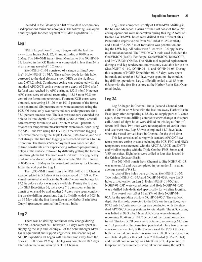
Expedition Summary 23
Included in the Glossary is a list of standard or commonly used operations terms and acronyms. The following is an opera-tional synopsis for each segment of NGHP Expedition 01.
Leg 1
NGHP Expedition 01, Leg 1 began with the last line away from Indira Dock 22, Mumbai, India, at 0700 hr on 5 May. The 246-NMI transit from Mumbai to Site NGHP-01-01, located in the KK Basin, was completed in less than 24 hr at an average speed of 10.2 knots.
Site NGHP-01-01 consisted of a single drilling? cor-ing?: Hole NGHP-01-01A. The seafloor depth for this hole, corrected to the dual elevator stool (DES) on the rig floor, was 2,674.2 mbrf. Continuous coring was conducted with the standard APC/XCB coring systems to a depth of 289.0 mbsf. Refusal was reached by APC coring at 152.8 mbsf. Nineteen APC cores were obtained, recovering 145.58 m or 97.8 per-cent of the formation penetrated. Fourteen XCB cores were obtained, recovering 131.76 m or 101.2 percent of the forma-tion penetrated. Six pressure cores were attempted using the PCS. Of these, only two recovered core under pressure for a 33.3 percent success rate. The last pressure core extended the hole to its total depth of 290.0 mbsf (2,964.2 mbrf). Overall core recovery for the site was 279.26 m or 98.0 percent. A total of six temperature measurements were taken: four using the APCT and two using the DVTP. Three wireline logging runs were made using the Triple Combo, FMS-Sonic, and VSP tool strings. The first two logging runs reached within 4 to 6 m of bottom. The third (VSP) deployment was cancelled due to time constraints after experiencing software/programming delays at the surface followed by difficulty getting the tools to pass through the bit. The hole was filled with 10.5 ppg heavy mud and abandoned, and operations at Site NGHP-01 ended at 0345 hr on 10 May as the vessel got underway for Chennai, India: the end port for Leg 1.
The 1,393-NMI transit from Site NGHP-01-01 to Chennai was completed in 5.3 days at an average speed of 10.9 kt. The vessel remained at anchor in the South Chennai Anchorage for 15.5 hr before a dock was made available. During the first leg of NGHP Expedition 01, there were 7.1 days spent either in transit or on stand-by and another 3.9 days were spent conduct-ing on-site drilling operations. Leg 1 officially ended at 0624 hr on 16 May with the first line ashore at the Harbor Basin West Quay 4 (passenger terminal) in Chennai, India.
Leg 2
There was no drilling contractor crew change during the first Chennai port call; however, 3.3 days were spent re-supplying the ship and loading all of the Schlumberger MWD/LWD equipment and support engineers. The second leg of NGHP Expedition 01 began with the first line away from the dock at 1300 hr on 19 May. The leg was completed 18.3 days later when the vessel arrived back in Chennai.
Leg 2 was composed strictly of LWD/MWD drilling in the KG and Mahanadi Basins off the East coast of India. No coring operations were undertaken during this leg. A total of twelve LWD/MWD holes were drilled at ten different sites. Penetration depths varied from 50.3 mbsf to 350.0 mbsf, and a total of 2,995.8 m of formation was penetration dur-ing the LWD leg. All holes were filled with 10.5 ppg heavy mud and abandoned. The LWD/MWD tools used included the GeoVISION (RAB), EcoScope, SonicVISION, TeleSCOPE, and ProVISION (NMR). The NMR tool required replacement during a mid-leg rendezvous and was only available for use on Sites NGHP-01-10, NGHP-01-11, and NGHP-01-05. During this segment of NGHP Expedition 01, 4.8 days were spent in transit and another 13.5 days were spent on-site conduct-ing drilling operations. Leg 2 officially ended at 2145 hr on 6 June with the first line ashore at the Harbor Basin East Quay (coal dock).
Leg 3ALeg 3A began in Chennai, India (second Chennai port
call) at 1745 hr on 9 June with the last line away Harbor Basin East Quay after completing a 2.8 day re-supply port call. Once again, there was no drilling contractor crew change at this port call. A total of eight holes were drilled on this leg at four dif-ferent drill sites. Two sites were reoccupations of earlier sites and two were new. Leg 3A was completed 14.7 days later, when the vessel arrived back in Chennai for the third time.
This leg consisted of coring with standard APC/XCB sys-tems; pressure coring systems including the PCS, FPC, and HRC; temperature measurements with the APCT-3, APCT, and DVTP; and wireline logging with the Triple Combo, FMS-Sonic, and VSP tool suites. Eight holes were drilled at four sites located in the Krishna-Godavari Basin.
The 203 NMI transit from Chennai to Site NGHP-01-05 was uneventful and was completed in just under 21 hr at an average speed of 9.8 kt.
A total of five holes were drilled at Site NGHP-01-05. Two holes, NGHP-01-05A and NGHP-01-05B, were LWD holes drilled earlier on Leg 2. Holes NGHP-01-05C and NGHP-01-05D were cored holes, and Hole NGHP-01-05E was a drilled hole dedicated specifically for wireline logging.
The vessel was offset 10 m SW of Hole NGHP-01-05A for the spudding of Hole NGHP-01-05C. The seafloor depth for this hole, corrected to the DES on the rig floor, was 957.2 mbrf. Continuous coring was conducted with the stan-dard APC/XCB coring systems to total depth. The APC coring was halted at 98.3 mbsf. Nine APC cores were obtained, recovering 80.44 m or 102.7 percent of the formation pene-trated. Thirteen XCB cores were obtained, recovering 61.18 m or 51.1 percent of the formation penetrated. Only two pressure cores were attempted, both of which used the PCS. Of these, both recovered core under pressure for a 100.0 percent success rate. Total depth for this hole was 200.0 mbsf (1,157.2 mbrf) and overall core recovery was 142.83 m or 71.4 percent. Six temperature measurements were taken: one using the APCT

24 Indian National Gas Hydrate Program Expedition 01 Report
shoe, two using the APCT-3, and two using the DVTP. There was no wireline logging and this hole was filled with 10.5 ppg heavy mud and abandoned.
The vessel was offset 10 m NE of Hole NGHP-01-05A for the spudding of Hole NGHP-01-05D. The seafloor depth for this hole, corrected to the DES on the rig floor, was 955.1 mbrf. This hole was spudded with the APC; however, this system was used only to core through the SMI. The remainder of the hole was drilled using an XCB center bit and multiple pressure cores were taken in targeted gas hydrate “areas of interest”. There was no XCB coring done in this hole. APC coring ended at a depth of 35.9 mbsf. Four APC cores were obtained recovering 35.20 m or 98.1 percent of the formation penetrated. A total of eight pressure cores were attempted with five deployments successfully recovering core under pressure. Four pressure cores were attempted using the PCS. Of these, two deployments recovered core under pres-sure for a 50.0 percent success rate. Two pressure cores were attempted using the FPC. Of these, both recovered core under pressure. Two pressure cores were attempted using the HRC. One of these deployments recovered core under pressure for a 50.0 percent success rate. Another 157.1 m were drilled using an XCB center bit placing the total depth of the hole at 201.0 mbsf (1,156.1 mbrf). Overall core recovery was 39.75 m or 90.5 percent. Two additional temperature measurements were taken using the APCT to supplement those taken in Hole NGHP-01-05C. There was no wireline logging and the hole was filled with 10.5 ppg heavy mud and abandoned.
The vessel was offset 10 m NE of Hole NGHP-01-05A for the spudding of Hole NGHP-01-05E, the dedicated wireline logging hole. Seafloor depth was assumed to be the same as for Hole NGHP-01-05D (955.1 mbrf) and the hole was drilled to a total depth of 200.0 mbsf using an XCB center bit. Three suites of wireline logging tools were deployed. The Triple Combo and FMS-Sonic tool strings both reached total depth. The third suite of VSP tools reached to within 2.0 m of total depth. The VSP logging operations were conducted dur-ing daylight hours. Operating protocols adhered to the IODP standards for marine mammal watch/observations and for “soft” start-up of the seismic guns. Operations at Site NGHP-01-05 ended at 2000 hr on 15 June as the vessel got underway for Site NGHP-01-10.
The 15.5 NMI transit from Site NGHP-01-05 to Site NGHP-01-10 was completed in 2.5 hr at an average speed of 6.5 kt.
Four holes were drilled at Site NGHP-01-10. The first hole, NGHP-01-10A, was an LWD/MWD hole drilled earlier on Leg 2. Holes NGHP-01-10B through NGHP-01-10D were cored on Leg 3A and Hole NGHP-01-10D was also wireline logged.
The vessel was offset 10 m SE of Hole NGHP-01-10A for the spudding of Hole NGHP-01-10B. The seafloor depth for this hole, corrected to the DES on the rig floor, was 1,049.4 mbrf. Continuous coring was conducted with the standard APC/XCB coring systems to total depth. The APC coring was halted early due to the expectation of very shallow
hydrates at this site. Two APC cores were obtained, recover-ing 12.97 m or 102.9 percent of the formation penetrated. Twenty-one XCB cores were obtained, recovering 37.04 m or only 20.1 percent of the formation penetrated. Eight pressure cores were attempted using all three pressure coring systems (PCS/FPC/HRC). Four of the eight attempts recovered core under pressure for a 50.0 percent success rate. Three pressure cores were taken using the PCS. Of these, two recovered core under pressure for a 66.7 percent success rate. Three pressure cores were attempted using the FPC. Of these, two recovered core under pressure for a 66.7 percent success rate. Two pres-sure cores were attempted using the HRC and both recovered core, although not under pressure. Total depth for this hole was 204.9 mbsf (1,254.3 mbrf) and overall core recovery was 55.53 m or 27.1 percent. Three DVTP temperature measure-ments were taken. There was no wireline logging and this hole was filled with 10.5 ppg heavy mud and abandoned.
The vessel was offset 10 m NW of Hole NGHP-01-10A for the spudding of Hole NGHP-01-10C. The seafloor depth for this hole was not clearly defined. Due to a space-out error the hole was spudded 1-stand of drill pipe too low (below seafloor). The first and only APC core was recovered full and included gas hydrate. Based upon the Hole NGHP-01-10D seafloor (established later), the cored interval for this hole was estimated to be approximately 23.1 mbsf to 32.6 mbsf (TD). It was treated as a hole only because gas hydrate samples were taken for analysis.
Hole NGHP-01-10D was subsequently spudded and the seafloor depth for this hole, corrected to the DES on the rig floor, was 1,050.4 mbrf. This hole was spudded with the APC and this system was used to core through the SMI to a depth of 32.6 mbsf. Four APC cores were obtained, recover-ing 32.85 m or 100.8 percent of the formation penetrated. The remainder of the hole was continuously cored to total depth using the XCB. Multiple pressure cores were taken along the way in targeted gas hydrate areas of interest. Eighteen XCB cores were obtained, recovering 88.62 m or 54.0 percent of the formation cored. The significant improvement in core recovery over Hole NGHP-01-10B was attributed to a change from the regular hard- and soft-formation, spring-loaded, finger-style core catcher combination to one using the 4-petal “full closure” flapper-style core catcher. Seven pressure cores were attempted in this hole with three successfully recover-ing core under pressure: a 42.9 percent success rate. Three pressure cores were attempted using the PCS. Only one of the three obtained core under pressure: a 33.3 percent success rate. Two pressure cores were attempted using the FPC and neither of these recovered core under pressure. Two pressure cores were attempted using the HRC; both of these recovered core under pressure. Total depth of the hole reached 203.8 mbsf (1,254.2 mbrf) and overall core recovery was 127.43 m or 62.5 percent. Three additional temperature measurements were taken in this hole using the DVTP. These were to supplement those taken in Hole NGHP-01-10B. Three suites of wireline logging tools were deployed. The Triple Combo tools were stopped by a bridge at 152.6 mbsf and logs were only obtained

Expedition Summary 25
above that point. After reaming the hole, the FMS-Sonic tool string was deployed once again and was only able to reach a depth of 160.0 mbsf. The third suite of tools, the VSP, reached only 144.6 mbsf. Logging operations using VSP tools were conducted during daylight hours. Operating protocols adhered to the IODP standards for marine mammal watch/observations and for “soft” start-up of the seismic guns. Operations at Site NGHP-01-10 ended as the bit cleared the seafloor at 1835 hr on 21 June.
The move to the next site was made in DP mode with the drill pipe suspended 3-stands above the seafloor. The DP move to Site NGHP-01-12 was completed in ~1.0 hr arriving on-site at 2100 hr on 21 June.
Site NGHP-01-12 was a new site (not previously LWD/MWD drilled) and consisted of a single cored hole. The seafloor depth for Hole NGHP-01-12A, corrected to the DES on the rig floor, was 1,045.8 mbrf. This hole was spudded with the APC and this system was again used to core through the sulfate-methane-interface. The remainder of the hole was drilled using an XCB center bit. Multiple pressure cores were taken at targeted gas hydrate “areas of interest” and each pressure coring “package” was set up with a single XCB core. Coring with APC ended at a depth of 24.7 mbsf. Three APC cores were obtained, recovering 26.28 m or 106.4 percent of the formation penetrated. Only four XCB cores were obtained from this hole with 20.60 m recovered or 65.6 percent of the formation penetrated. Six pressure cores were attempted with only two deployments successfully recovering core under pressure: a 33.3 percent success rate. Two pressure cores were attempted using the PCS; of these, one recovered core without pressure and one recovered pressure without core. Two pres-sure cores were attempted using the FPC. One recovered core under pressure for a 50.0 percent success rate. Two pressure cores were attempted using the HRC. Again, only one recov-ered core under pressure: a 50.0 percent success rate. Another 88.8 m were drilled using an XCB center bit, placing the total depth of the hole at 150.9 mbsf (1,196.7 mbrf). Overall core recovery was 50.23 m or 80.9 percent. The hole was then terminated earlier than planned because of stuck pipe and hole instability while attempting to take an FPC core at 150.9 mbsf. After unsuccessfully fighting hole problems, further cor-ing was suspended, and the hole was ultimately abandoned. Because of the proximity to Site NGHP-01-10, there were no temperature measurements taken or wireline logging con-ducted in this hole. Operations at Site NGHP-01-12 were com-pleted when the bit cleared the seafloor at 0035 hr on 23 June.
The 150 m move to the NW of Site NGHP-01-12 required only 30 min in DP mode with the drill string sus-pended below the ship.
Site NGHP-01-13 was added to the drilling schedule as another new site (not previously LWD/MWD drilled). This site was drilled strictly as a wireline logging hole. The original intent was to log Hole NGHP-01-12A; however, the premature abandonment of that hole precluded logging as an option. The new hole was not drilled as Hole NGHP-01-12B because it was felt that hole stability was directly related to gas-hydrate
concentration in the formation. Therefore, a 150-m move was made (far enough for a new site number) in order to get back into the richer hydrate zone. All holes drilled at Site NGHP-01-10 experienced severe hole instability once below or near the BSR. By moving back toward Site NGHP-01-10 and drilling at an “intermediate” site, it was felt that gas-hydrate concentrations would likely be higher and therefore the poten-tial of maintaining hole stability for wireline logging would be greater.
Hole NGHP-01-13A was spudded at 0130 hr on 23 June and a seafloor depth, corrected to the rig floor DES, was estab-lished at 1,044.0 mbrf. The hole was drilled to a total depth of 200.0 mbsf using an XCB center bit. Only a single wireline log-ging run was made. The Triple Combo tool string was deployed and several hours were spent attempting to get the tools through the bit and out into open hole. Eventually the problem was corrected and the wireline tools reached a depth of 149.0 mbsf. Wireline logging commenced at that point. There was no desire to spend additional time at this site, so once the Triple Combo logging run was completed, Hole NGHP-01-13A was filled with 10.5 ppg heavy mud and abandoned. Operations at Site NGHP-01-13 ended at 0536 hr on 24 June as the vessel got underway for Chennai (the end port for Leg 3A).
The 180 NMI transit from Site NGHP-01-13 to the Chennai pilot station was completed in 19.5 hr at an average speed of 9.2 kt. There, the vessel stood-by for 5.75 hr before being advised by the harbor authority that a dock was avail-able. On NGHP Expedition 01, Leg 3A there were 1.2 days spent in transit and another 13.5 days were spent on-site con-ducting drilling operations. Leg 3A officially ended at 0816 hr on 25 June with the first line ashore at the Quay 3 South (coal dock), Chennai, India.
Leg 3BLeg 3B began after completing the third Chennai port
call. The last line was released at 1530 hr on 28 June from the Chokhani International North Pier after completing a 3.3 day re-supply port call. This port call was interrupted briefly (~1 hr) when the vessel was required by the port authority to relocate from its arrival berth at Quay 3 South (coal dock) to another berth at the Chokhani International North Pier. The drilling contractor also completed a crew change dur-ing this port call and part of the science compliment was also replaced. Leg 3B was officially over 19.0 days later at 1600 hr on July 17 after completing the last hole of the leg at Site NGHP-01-16A.
This leg consisted of coring with standard APC/XCB systems; pressure-coring systems including the PCS, FPC, and HRC; temperature measurements with the APCT-3, APCT, and DVTP; and wireline logging with the Triple Combo, FMS-Sonic, and VSP tool suites. Eight holes were drilled at five sites, all located in the KG Basin. Two sites were reoccupations of earlier sites and three were new.
The 192.0 NMI transit from Chennai to Site NGHP-01-03 was completed in 19 hr at an average speed of 10.1 kt.

26 Indian National Gas Hydrate Program Expedition 01 Report
Three holes were drilled at Site NGHP-01-03. The first hole, NGHP-01-03A, was an LWD hole drilled earlier on Leg 2. Holes NGHP-01-03B and NGHP-01-03C were holes cored during Leg 3B. The latter was also wireline logged.
The vessel was offset 10 m SW of Hole NGHP-01-03A for the spudding of Hole NGHP-01-03B. The seafloor depth for this hole, corrected to the DES on the rig floor, was 1,085.1 mbrf. Continuous coring was conducted with the stan-dard APC/XCB coring systems to total depth. The APC coring was halted at 62.4 mbsf. Seven APC cores were obtained, recovering 65.16 m or 104.4 percent of the formation pen-etrated. Twenty seven XCB cores were obtained, recovering 186.54 m or 80.2 percent of the formation penetrated. Five pressure cores were attempted using all three of the pressure-coring systems available (PCS, FPC, and HRC). Two of five attempts resulted in the recovery of core under pressure: a 40.0 percent success rate. The PCS was deployed three times with one core recovered under pressure; a 33.3 percent success rate. The FPC was deployed once recovering core under pres-sure. The HRC was also deployed once but failed to recover core or pressure. Total depth for this hole was 300.0 mbsf (1385.1 mbrf) and overall core recovery was 255.33 m or 85.1 percent. Six temperature measurements were taken; three using the APCT-3 and three using the DVTP. There was no wireline logging and the hole was filled with 10.5 ppg heavy mud and abandoned.
The vessel was offset 10 m NE of Hole NGHP-01-03A for the spudding of Hole NGHP-01-03C. The seafloor depth for this hole, corrected to the DES on the rig floor, was 1,086.0 mbrf. This hole was spudded with the APC and this system was used to core through the SMI. The remainder of the hole was drilled using an XCB center bit with multiple pressure cores taken at targeted gas hydrate “areas of inter-est”. There was no XCB coring done in this hole. The APC coring mended at a depth of 28.5 mbsf. Three APC cores were obtained, recovering 26.79 m or 104.5 percent of the forma-tion penetrated. A total of seven pressure cores were attempted in Hole NGHP-01-03C with only one deployment successfully recovering core under pressure: a 14.3 percent success rate. Three pressure cores were attempted using the PCS. Of these, only one deployment recovered core under pressure for a 33.3 percent success rate. Three pressure cores were attempted using the FPC and one was attempted using the HRC. None of these deployments recovered core under pressure. Another 264.5 m were drilled using an XCB center bit, placing the total depth of the hole at 300.0 mbsf (1,386.0 mbrf). Overall core recovery was 34.93 m or 98.4 percent. No additional tem-perature measurements were taken. Three suites of wireline logging tools were deployed. The Triple Combo and FMS-Sonic tool strings both reached total depth; however, between logging runs, the pipe had to be lowered to 106.0 mbsf to clear a bridge at 68.0 mbsf. While deploying the VSP logging tools, another obstruction was encountered at 104.0 mbsf. After some effort, the tools were worked down to 120.0 mbsf but could not be advanced beyond that point. The tools were recovered back to the bit and 3 hr were spent getting them
back into the pipe. Eventually the VSP tools were recovered to the rig floor and further VSP logging efforts were cancelled for this hole. Operations at Site NGHP-01-03 ended at 2045 hr on 4 July as the vessel got underway for Site NGHP-01-07.
The 58.0-NMI transit from Site NGHP-01-03 to Site NGHP-01-07 was completed in 5.0 hr at an average speed of 11.6 kt. The first positioning beacon deployed at this loca-tion inexplicably switched into a one-half repetition rate so a second beacon was deployed for the duration of the site. Both beacons were successfully recovered at the conclusion of site operations.
Four holes were drilled at Site NGHP-01-07. The first hole, NGHP-01-07A, was an LWD/MWD hole drilled earlier on Leg 2. Hole NGHP-01-07B was a cored hole while Holes NGHP-01-07C and NGHP-01-07D were primarily designed as wireline-logging holes with little or no coring attempted.
The vessel was offset 10 m SE of Hole NGHP-01-07A for the spudding of Hole NGHP-01-07B. The seafloor depth for this hole, corrected to the DES on the rig floor, was 1,295.8 mbrf. Continuous coring was conducted with the stan-dard APC/XCB coring systems to total depth. Coring with the APC was halted at a depth of 78.7 mbsf. Nine APC cores were obtained, recovering 80.71 m or 102.6 percent of the forma-tion penetrated. Fifteen XCB cores were obtained, recovering 93.37 m or 74.2 percent of the formation penetrated. Seven pressure cores were attempted, using all available pres-sure coring systems (PCS/FPC/HRC). Four of the attempts recovered core under pressure for a 57.1 percent success rate. Three pressure cores were taken using the PCS and all three recovered core under pressure. Three pressure cores were also attempted using the FPC. All three recovered core; however none were under pressure. One pressure core was attempted using the HRC and this was successful recovering both core and pressure. Total depth for this hole was 211.6 mbsf (1507.4 mbrf) and overall core recovery was 180.28 m or 85.2 percent. Five temperature measurements were taken; three with the APCT-3 and two with the DVTP. This hole was terminated short of its original depth objective (260.0 mbsf) due to a damaged (overheated and swollen) XCB cutting shoe that prevented recovery of core barrel 31X. This precluded any chance of wireline logging and the hole was filled with 10.5 ppg heavy mud and abandoned. Core 31X was ultimately recovered after recovering the drill string back aboard the ship. Drilling at Hole NGHP-01-07B was ended when the bit cleared the seafloor at 0440 hr on 7 July.
During the pipe trip back to the surface, the vessel was offset 10 m NW of Hole NGHP-01-07A for the spudding of Hole NGHP-01-07C. This hole was a dedicated wireline-logging hole. The seafloor depth for the hole was assumed to be the same as that of Hole NGHP-01-07B (1,295.8 mbrf). Hole NGHP-01-07C was spudded and drilled down to a depth of 184.2 mbsf when the driller noted a 350 psi drop in circulat-ing pressure. The hole, up to that point, had been stable and free of cuttings build-up. Since this much fluctuation in circu-lating pressure had not been experienced at any of the other holes drilled in the area, the prudent thing to do was POOH

Expedition Summary 27
and confirm that there was not a washout or crack in any of the BHA components. The hole was displaced with 10.5 ppg heavy mud and the pipe was pulled clear of the seafloor at 2005 hr on 7 July ending Hole NGHP-01-07C.
Once clear of the seafloor, the subsea TV camera was deployed on the VIT, and mud was circulated to ensure that there was not a crack in the drill pipe. The drill string was then recovered and the entire BHA was NDT inspected. No evidence of any crack or washout was identified. What caused the fluctuation in pump pressure remains a mystery.
The vessel was offset 10 m to the NE of Hole NGHP-01-07A for the spudding of Hole NGHP-01-07D. This hole was planned as a dedicated wireline logging hole with a few XCB cores to be taken at the bottom to replace those lost from the previous coring attempts. Seafloor depth was assumed to be the same as that of Holes NGHP-01-07B and NGHHP-01-07C (1295.8 mbrf). The hole was drilled to a total depth of 231.2 mbsf with an XCB center bit. This was followed by four XCB cores that took the hole to a total depth of 260.0 mbsf. The XCB recovered 32.65 m or 113.4 percent of the forma-tion penetrated. A single DVTP temperature measurement was taken at TD to supplement the temperature data gathered from Hole NGHP-01-07B. Three suites of wireline logging tools were deployed. The Triple Combo reached TD at 260.0 mbsf. The VSP tool string was deployed next in order to keep the seismic guns firing during daylight hours. This tool string also reached TD VSP logging operations were restricted to daylight hours in conformance with the IODP operating protocols for marine mammal watch/observations and for “soft” start-up of the seismic guns. The third wireline run, with the FMS-Sonic tool string, also reached total depth; however, problems were encountered reentering the bit with both passes of the FMS-Sonic tools. Operations at Site NGHP-01-07 ended at 0600 hr on 10 July as the vessel got underway for Site NGHP-01-14.
The 44.0 NMI transit from Site NGHP-01-07 to Site NGHP-01-14 was completed in 5 hr at an average speed of 11.6 kt.
Site NGHP-01-14 was one of the alternate sites listed in the prospectus and consisted of a single hole: Hole NGHP-01-14A. The seafloor depth for this hole, corrected to the DES on the rig floor, was 906.6 mbrf. Continuous coring was conducted with the standard APC/XCB coring systems to a depth of 180.0 mbsf. The APC coring was halted at 71.0 mbsf. Eight APC cores were obtained ,recovering 72.96 m or 102.8 percent of the formation penetrated. Eleven XCB cores were obtained, recovering 76.89 m or 73.2 percent of the formation penetrated. Four pressure cores were attempted using all three of the pressure coring systems available (PCS, FPC, and HRC). Only one of four attempts resulted in the recovery of core under pressure: a 25.0 percent success rate. The PCS was deployed twice and recovered core each time but failed to retain pressure on both deployments. The FPC was deployed once and it also recovered core but not under pressure. The HRC was deployed once and it successfully recovered core under pressure. Total depth for this hole was 180.0 mbsf (1,086.6 mbrf). Overall core recovery for the
site was 152.76 m or 84.9 percent. A total of six temperature measurements were taken: three using the APCT-3 and three using the DVTP. Three wireline logging runs were made using the Triple Combo, FMS-Sonic, and VSP tool strings. All three logging runs reached total depth of 180.0 mbsf. As on all earlier sites, the VSP logging operations were restricted to daylight hours and operating protocols adhered to the IODP standards for marine mammal watch/observations and for “soft” start-up of the seismic guns. The hole was filled with 10.5 ppg heavy mud and abandoned. Once the drill string was recovered, the hydrophones were raised and secured in preparation for a DP move to the next site. Operations at Site NGHP-01-14 ended at 2045 hr as the vessel got underway in DP mode for Site NGHP-01-15.
The 4.5-NMI DP move from Site NGHP-01-14 to Site NGHP-01-15 was completed in 1.25 hr at an average speed of 3.6 kt.
Site NGHP-01-15 was another alternate site listed in the prospectus and again consisted of a single hole: Hole NGHP-01-15A. The seafloor depth for this hole, corrected to the DES on the rig floor, was 937.9 mbrf. Continuous coring was con-ducted with the standard APC/XCB coring systems to a depth of 200.0 mbsf. Coring with the APC was halted at 76.1 mbsf. Eight APC cores were obtained, recovering 74.22 m or 97.5 percent of the formation penetrated. Thirteen XCB cores were obtained, recovering 93.71 m or 78.2 percent of the formation penetrated. Four pressure cores were attempted using only the IODP/TAMU PCS and the Fugro FPC pressure coring systems. Three of the four pressure-coring attempts resulted in the recovery of core under pressure: a 75.0 percent success rate. The PCS was deployed twice recovering core under pressure on one deployment; a 50.0 percent success rate. The FPC was also deployed twice, recovering core under pres-sure on both attempts. The HRC was not deployed in this hole. Total depth for this hole was 200.0 mbsf (1,137.9 mbrf). Over-all core recovery for the site was 170.61 m or 85.3 percent. A total of five temperature measurements were taken: three using the APCT-3 and two with the DVTP. Two wireline logging runs were made using the Triple Combo and FMS-Sonic tool strings. The VSP tools were not deployed at this site due to the close proximity to Site NGHP-01-14. Both logging runs reached total hole depth of 200.0 mbsf. The hole was filled with 10.5 ppg heavy mud and abandoned. Operations at Site NGHP-01-15 ended at 0000 hr on 15 July when the vessel got underway for Site NGHP-01-16.
The 43.0 NMI transit from Site NGHP-01-15 to Site NGHP-01-16 was completed in 4.5 hr at an average speed of 9.6 kt.
Site NGHP-01-16 was a “step-out” site from Site NGHP-01-07. This site consisted of a single drilling hole: Hole NGHP-01-16A. The seafloor depth for this hole, corrected to the DES on the rig floor, was 1264.5 mbrf. Continuous coring was conducted with the standard APC/XCB coring systems to a total depth of 217.0 mbsf (1481.5 mbrf). APC coring was halted at 65.8 mbsf. Eight APC cores were obtained, recovering 69.84 m or 106.1 percent of the formation penetrated. Sixteen

28 Indian National Gas Hydrate Program Expedition 01 Report
XCB cores were obtained, recovering 94.06 m or 63.9 percent of the formation penetrated. Four pressure cores were attempted using all three of the pressure coring systems available (PCS, FPC, and HRC). Two of the four attempts resulted in recovery of core under pressure: a 50.0 percent success rate. The PCS recovered core under pressure on one of two deployments: a 50.0 percent success rate. The FPC was deployed once and it recovered core but not under pressure. The HRC was deployed once and it successfully recovered core under pressure. Overall core recovery for the site was 166.86 m or 76.9 percent. Eight temperature measurements were taken: three using the APCT-3 and five using the DVTP. Two wireline logging runs were made using the Triple Combo, FMS-Sonic tool strings. Both logging runs reached total depth of 217.0 mbsf. Logging with the VSP was not scheduled for this site because of its close proximity to Site NGHP-01-07, where successful VSP logs had already been obtained. The hole was filled with 10.5 ppg heavy mud and abandoned. During NGHP Expedition 01, Leg 3B 1.4 days were spent in transit while 17.6 days were spent on-site conducting drilling operations. Operations at Site NGHP-01-16 and Leg 3B ended at 1600 hr on 17 July as the vessel got underway for Site NGHP-01-17.
Helicopter Rendezvous
While operating at Site NGHP-01-16, there were three helicopter transfers of personnel using a Canadian S76 12-passenger helicopter dispatched to/from the Rajahmundry heliport where all India Customs and Immigration procedures were handled. The helicopter transfers allowed several of the scientific/technical staff and two ODL personnel to be changed out. This operation replaced what was originally planned as another Chennai port call and saved 4.5 operating days for the expedition. Crossover between appropriate science/lab person-nel occurred between the first and last flights. All total, 23 per-sonnel were changed out for NGHP Expedition 01, Leg 4.
Leg 4
Leg 4 began as the ship got underway at 1600 hr on 17 July after completing the helicopter personnel exchanges and operations at Site NGHP-01-16. Leg 4 was completed 30.6 days later when the vessel arrived back in Chennai for the fourth and final time.
This leg consisted of coring with standard APC/XCB systems; pressure-coring systems including the PCS, FPC, and HRC; temperature measurements with the APCT-3 and DVTP; and wireline logging with the Triple Combo, FMS-Sonic, and VSP tool suites. A total of ten holes were drilled at five new drill sites located in the Andaman convergent margin, the Mahanadi Basin, and the KG Basin.
The 746.0-NMI transit from Site NGHP-01-16A to Site NGHP-01-17 was completed in 3.0 days at an average speed of 10.5 kt.
Two holes were drilled at Site NGHP-01-17. Hole NGHP-01-17A was the first hole of NGHP Expedition 01 drilled in the Andaman convergent margin and was the second-deepest penetration drilled on Expedition NGHP-01. The seafloor depth for this hole, corrected to the DES on the rig floor, was 1,356.0 mbrf. Continuous coring was con-ducted with the standard APC/XCB coring systems to total depth. Coring with the APC advanced the hole to 118.5 mbsf. Thirteen APC cores were obtained, recovering 122.66 m or 103.5 percent of the formation penetrated. A total of 60 XCB cores were taken from this hole, recovering 434.31 m or 77.1 percent of the formation penetrated. Ten pressure cores were attempted, using all three pressure-coring systems (PCS/FPC/HRC). Of these, seven successfully recovered core under pressure. Four pressure cores were attempted using the PCS and three recovered core under pressure: a 75.0 percent suc-cess rate. Three pressure cores were attempted using the FPC with only one recovering core under pressure: a 33.3 percent success rate. Another three pressure cores were attempted using the HRC and two of these recovered core under pres-sure: a 66.7 percent success rate. Total depth for this hole was 691.6 mbsf (2,047.6 mbrf) and overall core recovery was 563.55 m or 81.5 percent. A total of 11 temperature measure-ments were taken in this hole: three using the APCT-3 shoe and eight using the DVTP. Wireline-logging attempts were abandoned due to bridging or ledges preventing any tool deployment in open holes. The hole was filled with 10.5 ppg heavy mud and abandoned.
The vessel was offset 20 m S of Hole NGHP-01-17A for the spudding of Hole NGHP-01-17B. This was a dedicated wireline-logging hole and was the deepest hole drilled on Expedition NGHP-01. The seafloor depth for this hole was assumed to be the same as the previous hole (1,356.0 mbrf). The hole was drilled to a total depth of 718.0 mbsf using an XCB center bit. Three suites of wireline logging tools were deployed. The Triple Combo and FMS-Sonic tool strings both reached total depth. The third suite of VSP tools reached to 629.0 mbsf, or within 89.0 m of total depth. The VSP log-ging operations were conducted during daylight hours and operating protocols adhered to the IODP standards for marine mammal watch/observations and “soft” start-up of the seismic guns. Operations at Site NGHP-01-17 ended at 2030 hr on 29 July as the vessel got underway for Site NGHP-01-18.
The 726.0-NMI transit from Site NGHP-01-17 was com-pleted in 88.0 hr at an average speed of 8.3 kt. The transit took 0.8 days longer than anticipated due to a severe low pressure cell that enveloped nearly the entire Bay of Bengal. Strong head winds (40–50 kt) and heavy seas/swells (15–20 ft) were experienced during the last 2 days of the transit, limiting the vessel’s speed to an average of 6.6 kt. The vessel was switched from cruise mode to DP control at 1,234 hr on 2 August.
Site NGHP-01-18 consisted of a single Hole NGHP-01-18A. After tripping the drill string to the seafloor, the ves-sel went into standby mode while 2.5 hr were spent waiting on weather (WOW). The delay resulted from a very strong

Expedition Summary 29
current (>3 kt) aligned with strong (>40 kt) winds leading to the inability of the vessel to stay on location, even with full power to the main propulsion shafts. It was not considered prudent to attempt spudding the hole under these condi-tions. Ultimately, the hole was spudded and a seafloor depth, corrected to the DES on the rig floor, was established at 1,391.4 mbrf. Coring proceeded using the APC coring system to a depth of 54.9 mbsf (1,431.5 mbrf) before coring was halted once again for another 1.5 hr WOW due to excessive heave (>6 m). Coring with the APC was eventually completed to a depth of 115.9 mbsf. The XCB coring system was used to achieve the total depth of 190.0 mbsf. Twelve APC cores were obtained recovering 113.54 m or 101.5 percent of the forma-tion penetrated and eight XCB cores were obtained, recov-ering 68.07 m or 91.9 percent of the formation penetrated. Because of excessive heave (>4 to >6 m) all pressure coring and wireline logging was cancelled. Overall core recovery for the site was 181.61 m or 97.6 percent. Four successful temperature measurements were taken; two using the APCT-3 and two using the DVTP. The hole was filled with 10.5 ppg heavy mud and abandoned. Operations at Site NGHP-01-18 ended at 0200 hr on 4 August as the vessel got underway for Site NGHP-01-19.
The 12.0-NMI transit from Site NGHP-01-18 to Site NGHP-01-19 was arduous. The large low pressure cell that enveloped a large portion of the Bay of Bengal led to strong winds (30–40 kt) and heavy seas/swells (15–20 ft) throughout the transit. In addition, a strong current from variable direc-tions first assisted and then impeded progress. The move between sites was originally planned as a DP transit with the current assisting the move. The DP move was preferred since the resultant heading in transit mode would have led to major vessel rolling. At 0200 hr on 4 August the ship began mov-ing to the next site in heavy seas and very high swells. Soon into the move, however, the current shifted directions causing further reduction in speed. During the move a propulsion shaft had to be taken offline due to an overheating gearbox. With one shaft offline, the vessel barely made steerage way and for a while was actually being pushed back toward the previous site. The off-line shaft was eventually regained; however, because of the slow rate of progress during the initial part of the move it was decided that the remaining distance should be conducted in cruise mode. Even in transit mode, the speed was limited to less than 4 kt since shaft RPM had to be vastly reduced to keep the propellers from coming out of the water and overspeeding. The 12.0-NMI transit was ultimately com-pleted in 12.8 hr at an overall (DP plus cruise mode) average speed of 0.9 kt.
Originally, only one hole was scheduled for drilling at Site NGHP-01-19; however, due to hole instability in Hole NGHP-01-19A, a separate dedicated wireline-logging hole, NGHP-01-19B, was required. The seafloor depth for Hole NGHP-01-19A, corrected to the DES on the rig floor, was 1,434.2 mbrf. Continuous coring was conducted with the standard APC/XCB coring systems to a depth of 305.0 mbsf. Coring with the APC
was halted at 98.3 mbsf due to incomplete stroke of the coring tool. Eleven APC cores were obtained, recovering 97.09 m or 103.0 percent of the formation penetrated. Twenty-one XCB cores were obtained, recovering 168.47 m or 86.1 percent of the formation penetrated. There were six pressure cores attempted using all three of the pressure-coring systems available (PCS, FPC, and HRC). Three of six attempts resulted in the recovery of core under pressure: a 50.0 percent success rate. The PCS was deployed twice and recovered core under pressure on one deployment. The FPC was also deployed twice failing to recover core under pressure on both attempts. The HRC was deployed twice and successfully recovered core under pressure on both deployments. Total depth for this hole was 305.0 mbsf (1,739.2 mbrf). Overall core recovery for the hole was 271.14 m or 91.6 percent of the formation penetrated. A total of eight tem-perature measurements were taken: three using the APCT-3 and five using the DVTP. Six of these recovered useable temperature data. The hole was displaced with 100 bbl of 10.5-ppg Sepiolite mud prior to logging. Only one wireline-logging run was made in this hole. That was with the Triple Combo tool string and this string was unable to pass below 145.8 mbsf. Logs were obtained above this point and the decision was made to drill a dedicated logging hole to complete the wireline logging program.
The vessel was offset 10 m SW of Hole NGHP-01-19A on a bearing of 228° for the spudding of Hole NGHP-01-19B. Although this was to be a drilled hole dedicated to recovering a full suite of wireline logs, it was also used as an opportunity to recover three shallow APC cores for future high-resolution sedimentological studies. The seafloor depth for Hole NGHP-01-19B, corrected to the DES on the rig floor, was 1,433.2 mbrf. Three APC cores were obtained to a depth of 26.3 mbsf, recov-ering 97.09 m or 103.0 percent of the formation penetrated. The hole was then drilled to a total depth of 280.0 mbsf using an XCB center bit and was displaced with 100 bbl of 10.5-ppg Sepiolite mud. Overall core recovery for the site was 296.82 m or 92.1 percent. Another 262.7 m were drilled using an XCB center bit. Three suites of wireline logging tools were deployed. The Triple Combo tool string reached TD at 280.0 mbsf; how-ever, because of tight hole, it was unlikely the lighter-weight VSP tool would have been able to reach this same depth. The drill string was lowered to a depth of 177.3 mbsf and the VSP tool string was subsequently deployed to a depth of 262.8 mbsf. Logging operations with the VSP were conducted during daylight hours and operating protocols adhered to the IODP standards for marine mammal watch/observations and for “soft” start-up of the seismic guns. After recovering the VSP tools the drill string was raised back to the original 61.8 mbsf and the FMS-Sonic tool string was deployed to a depth of 266.8 mbsf. Operations at Site NGHP-01-19 ended at 0354 hr on 9 August as the vessel got underway for a return visit to Site NGHP-01-18.
The vessel transited north to the previously occupied Site NGHP-01-18 (MNGH-Gap Site) to recover the position-ing beacon left at that site earlier. Beacon recovery at this site was not initially attempted because the rough sea state and

30 Indian National Gas Hydrate Program Expedition 01 Report
strong current conditions prevalent at the time significantly increased the potential of beacon loss. The 12.0-NMI transit to Site NGHP-01-18 was completed in 1.75 hr at an aver-age speed of 7.5 kt. After recovering the beacon, the vessel departed for Site NGHP-01-20 at 0700 hr on 9 August. The 301-NMI transit from Site NGHP-01-18 to Site NGHP-01-20 was completed in 32.25 hr at an average speed of 9.3 knots.
Originally, only one hole was scheduled for drilling at this site. However, the severe hole instability and packing-off experienced in Hole NGHP-01-20A required that a sec-ond attempt be made in Hole NGHP-01-20B. Ultimately, the pressure-coring/logging objectives at the site were not achieved in either of these holes. The seafloor depth for Hole NGHP-01-20A, corrected to the DES on the rig floor, was 1,157.9 mbrf. Continuous coring was conducted with the standard APC/XCB coring systems to a depth of 148.8 mbsf. Coring with the APC was halted at a quite shallow 22.9 mbsf due to incomplete stroke. Three APC cores were obtained, recovering 22.95 m or 100.2 percent of the formation pen-etrated. Sixteen XCB cores were obtained, recovering 45.69 m or 36.6 percent of the formation penetrated. There was only one pressure core attempted in this hole; this was with the PCS, which recovered a small amount of core without pres-sure. Total depth for this hole was 148.8 mbsf (1,306.7 mbrf) and overall core recovery was 69.21 m or 46.5 percent. Only two temperature measurements were taken: one with the APCT-3 and one with the DVTP. Both were successful. This hole was abandoned prior to deployment of the first “package” of FPC/HRC pressure-coring tools. Several attempts were made during the coring operation to condition and stabilize the hole. These included multiple mud sweeps of varying sizes and frequencies as well as short trips of the drill string to get above the problem zones. In spite of these attempts, packing-off of the hole annulus persisted. This not only had a major impact on core quality and recovery, but it also precluded deployment of the pressure-coring tools and wireline-logging tool suites. The decision was made to drill another hole—we hoped that conditions would be better in the new hole. Hole NGHP-01-20A was filled with 60 barrels of 10.5 ppg Sepiolite mud and abandoned.
The vessel was offset 10 m NW of Hole NGHP-01-20A for the spudding of Hole NGHP-01-20B. The seafloor depth for this hole was assumed to be 1,157.9 mbrf, the same as the previous hole. The hole was drilled to a total depth of 148.8 mbsf using an XCB center bit. Four XCB cores were obtained recovering 3.67 m or 9.3 percent. This hole was abandoned at a total depth of 187.3 mbsf for the same reasons as Hole NGHP-01-20A; poor core quality and recovery, gener-ally poor hole conditions, and packing-off of the hole annulus. These conditions precluded any attempt at pressure coring or wireline logging. Overall core recovery for the site was 72.88 m or 38.9 percent. The hole was filled with 60 bbl of 10.5-ppg Sepiolite mud and abandoned, and operations at Site NGHP-01-20 ended at 1630 hr on 12 August as the vessel got underway in DP mode for Site NGHP-01-21.
The 3.3-NMI transit from Site NGHP-01-20 to Site NGHP-01-21 was made in DP mode. The move took 1 hr at an average speed of 3.3 kt.
Site NGHP-01-21 was a re-occupation of Site NGHP-01-10 (drilled earlier on Leg 3A). It was designated with a new site number because the activities scheduled for this site were different than those designated for the original site. Site NGHP-01-10 (located in the Godavari Basin) had provided the richest accumulation of gas hydrate observed during the expe-dition. Therefore, Site NGHP-01-21 was established in close proximity to Site NGHP-01-10, to obtain additional samples of gas hydrate for preservation in the remaining available dewars and pressure vessels, and to enable further delineation of the Site NGHP-01-10 accumulation. It was also an opportu-nity to recover additional cores under pressure using the FPC and HRC pressure coring systems. Another final attempt at obtaining wireline logging data from below the BSR was also planned. Ultimately there were three cored holes at this site because of hole stability problems associated with wireline logging, and due to the desire to obtain as many gas-hydrate core samples (pressurized and un-pressurized) as available shipboard containers would allow.
The seafloor depth for Hole NGHP-01-21A was assumed to be 1,049.0 mbrf, the same depth as nearby Hole NGHP-01-10A (the earlier hole was located 20 m to the NW). The hole was drilled to a depth of 48.4 mbsf, where a series of XCB half cores and FPC/HRC pressure cores were recov-ered. Seven XCB cores (one full core and six half cores) were obtained, recovering 25.06 m or 67.5 percent of the formation penetrated. There were six cores attempted using the FPC and HRC pressure-coring systems. Four of the six attempts resulted in the recovery of core under pressure: a 66.7 percent success rate. The FPC was deployed three times and recov-ered core under pressure on one deployment. The HRC was deployed three times as well and successfully recovered core under pressure on all three deployments. Total depth for this hole was 91.5 mbsf (1,140.5 mbrf). Overall core recovery for the hole was 30.36 m or 70.4 percent of the formation pen-etrated. Many excellent gas-hydrate samples were recovered and preserved in liquid nitrogen dewars, pressurized stor-age chambers, and Parr pressure vessels. The hole was filled with 30 bbl of 10.5-ppg Sepiolite mud and abandoned. Hole NGHP-01-21A was completed when the bit cleared the sea-floor at 1525 hr on 13 August.
The vessel was offset 150 m SE of Hole NGHP-01-10A on a bearing of 136° for the spudding of Hole NGHP-01-21B. This hole was planned as another pressure-core hole that was to be deepened to 200.0 mbsf for wireline logging with the Triple Combo and FMS-Sonic tool strings. The corrected depth for this hole was 1,056.6 mbsf, or 1.0 m deeper than at Hole NGHP-01-10. Therefore, the seafloor depth for Hole NGHP-01-21B, corrected to the DES on the rig floor, was assumed to be 1050.0 mbrf. The hole was drilled to a depth of 55.0 mbsf, where two pressure-core deployments were made. One of the two attempts resulted in the recovery of

Expedition Summary 31
core under pressure. The FPC was deployed once and did not recover core under pressure. The HRC was also deployed once and successfully recovered core under pressure. Overall core recovery for the hole was 0.5 m or 25.0 percent of the forma-tion penetrated. The hole was then drilled to a total depth of 200.0 mbsf, displaced with 60 bbl of 10.5-ppg Sepiolite mud, and the EOP was placed at 58.3 mbsf. The first logging attempt was unsuccessful when the Triple Combo tool string was unable to pass below a tight spot located at 101.0 mbsf. The hole was then cleaned up and deepened to 205.0 mbsf. The second logging attempt was made with the EOP left at a depth of 121.0 mbsf. This was to facilitate the recovery of logs in the lower portion of the hole. This was to be followed up with another logging effort in the upper part of the hole after raising the drill string back to the original EOP depth of 58.3 mbsf. However, the second logging attempt, again made with the Triple Combo tool string, was abandoned when the tool became stuck attempting to pass a tight spot located at 160.0 mbsf. Ultimately, the tool was successfully extracted from the formation and with effort was recovered back into the drill pipe. Further wireline logging in Hole NGHP-01-21B was abandoned. Operations in Hole NGHP-01-21B ended when the bit cleared the seafloor at 0030 hr on 15 August.
The vessel was offset 30 m SE of Hole NGHP-01-10A on a bearing of 136° for the spudding of Hole NGHP-01-21C. This hole was the last hole of Leg 4 and NGHP Expedition 01 and was scheduled so as to make use of the remaining available time. Four final pressure-coring system deployments were to be made in this last opportunity to collect pressurized gas-hydrate samples. The seafloor depth for Hole NGHP-01-21C was assumed to be 1,049.0 mbrf, the same as nearby Hole NGHP-01-21A (located 10 m away). The hole was drilled to a depth of 55.0 mbsf, where two pressure-core deployments were made. The hole was then advanced to 76.0 mbsf, where the final two pressure cores were attempted. There were a total of four cores attempted using the FPC and HRC pressure-cor-ing systems. All four deployments resulted in the recovery of core under pressure: a 100.0 percent success rate for both sys-tems. Total depth for this hole was 78.0 mbsf (1,127.0 mbrf) and overall core recovery was 3.88 m or 97.0 percent. The hole was filled with 30 bbl of 10.5-ppg Sepiolite mud and abandoned. Holes NGHP-01-21C and Site NGHP-01-21 were completed at 2130 hr on 15 August as the vessel got underway for Chennai.
The 188.0-NMI transit from Site NGHP-01-21 to Chennai, India, was completed in 21.2 hr at an average speed of 8.9 kt, and at 1845 hr on 16 August the anchor was let go in the Chennai Harbour anchorage. At 0340 hr the following morning the anchor was raised and first line ashore in Harbour Basin (Ambedkar Dock) was at 0510 hr on 17 August 2006. This officially ended NGHP Expedition 01, Leg 4 operations.
The primary activity for this fourth and final Chennai port call was the official demobilization of the vessel from the NGHP Expedition 01 gas-hydrate project. All standard cores and all Indian gas-hydrate samples were offloaded.
Total, there were 389 core boxes and 102 boxes of samples offloaded. In addition, 35 hydrate samples preserved in three liquid-nitrogen dewars (those that remained in India) were offloaded. The Directorate General of Hydrocarbons (DGH) arranged for transportation by refrigerated truck from Chennai to Mumbai (where the cores and samples were to be stored). By mutual decision with DGH personnel, it was decided that the five pressure cores retained in GeoTek pressure vessels and another twelve core samples stored in Parr pressure vessels would remain aboard the JOIDES Resolution until it arrived in Singapore. All Fugro, GeoTek, USGS, and IODP/TAMU hard-ware and equipment remained aboard the JOIDES Resolution, to be offloaded in Singapore. Other port call activities included customs inventory, clearance paperwork for the Fugro/GeoTek science equipment, the resolution of the vessel’s customs duties required for international clearance paperwork, and the receipt of some limited amount of foodstuffs. Three small liquid nitrogen dewars were topped off with LN2 and a limited quantity of drill water was taken aboard.
The pilot cable was aboard the vessel at 1900 hr on 19 August and the last line was let go from North Quay, Chennai, India, at 1912 hr. This officially brought the NGHP Expedition 01 Gas Hydrate Project to a successful conclusion.
Reporting Results
The following summary describes the shipboard-reporting processes followed during NGHP Expedition 01. Also included in this summary are details concerning the post-expedition production of the NGHP Expedition 01 Initial Results Volume.
At the beginning of Leg 3A, reporting duties were assigned to the leaders of individual laboratory groups. These duties included the drafting of their lab group’s initial find-ings into a report for each of the sites occupied throughout the expedition. Drafts also included figures and tables represent-ing the data procured during the core-analysis process. Drafts of the lab reports were submitted to the co-chief scientists for review and approval. Upon completion of the review, revisions were made and the draft was resubmitted. Upon receiving final approval, paper and electronic versions of the lab reports were submitted to the project secretariat for inclusion into the expe-dition Initial Results Volume All electronic files were secured on the internal hard drive of the YEOP computer and backed up to the external hard drive.
The text, tables, and figures for each lab report were cataloged by the project secretariat to ensure that all files were received from the laboratory group. To ensure version accuracy, submission dates were also recorded in the catalog. In addition to this lab report catalog, supplemental figure and table logs containing information on file types, software pro-grams used, and special formatting were also maintained.

32 Indian National Gas Hydrate Program Expedition 01 Report
Once all lab reports for a site were received and cata-loged, the individual lab reports were combined into one larger site report. Three copies of the site report were printed and placed into expedition notebook sets created for the Indian Science Party, the Co-Chief scientists, and the project secre-tariat for use during the post-cruise production of the Initial Results Volume.
At the end of NGHP Expedition 01, the electronic and paper files of the site reports were shipped to the project secre-tariat for production of the Expedition Initial Results Volume. During the production phase, a standard template was devel-oped to ensure that all site reports had a uniform appearance. The electronic files were transferred into the new template and made ready for the post-expedition editorial review meeting that was held in March 2007.
At the conclusion of the week-long editorial review meet-ing, all revisions were returned to the project secretariat for updating. After updating the site reports with the new material, the reports were mailed to the appropriate laboratory group leader for final approval. Over the course of several weeks, the site reports were returned to the project secretariat. Most of the site reports were returned with no updating necessary. Once final approval was received from the laboratory leads, the project secretariat imported the multiple figure and table files into the template, updated the figure and table callouts, and proofed the site reports. PDF files of the site reports were then produced, printed, bound, and delivered to the Expedition Project Manager for a final read-through and approval. Upon return of this galley proof, all updates were made to the files, all cross-reference and hypertext links were created, and the files were made ready for final production.
In addition to the site reports for the Initial Results Volume appendix materials were also prepared in PDF for-mat by the project secretariat, including Operations Schedules and Statistics, the Singapore Pressure-Core-Studies Report, the DVTP Temperature Calibration Report, and the Visual Core Descriptions (VCD). The WellCAD VCD sheets were provided to the project secretariat after the expedition as PDF files. These were combined into one VCD file per site. The Digital Image Scanner (DIS) images of the sections of core were converted and combined into one PDF file per core. The Infrared images were also converted into PDF files. Links to both the DIS core photo files and the Infrared image files were created within the VCD PDF files.
After the complete contents of the Initial Reports volume were prepared as a catalog of PDF files, a DVD-ROM was burned and proofed by the project secretariat. In addition, artwork for the DVD packaging (including the cover, an inside leaflet, and the disc face) was designed by the project sec-retariat. Once the Expedition Project Manager approved the DVD-ROM and its packaging, it was outsourced to a third-party DVD manufacturer for replication and assembly.
References Cited
Ahlbrandt, T.S., 2002, Future petroleum energy resources of the world: International Geology Review, v. 44, no. 12, p. 1092–1104.
Alam, M., Alam, M.M., Curray, J.R., Chowdhury, M., and Gani, M., 2003, An overview of the sedimentary history of the Bengal Basin in relation to the regional tectonic frame-work and basin fill history: Sedimentary Geology, v. 155, p. 179–208.
Bastia, R., 2006, An overview of Indian sedimentary basins with special focus on emerging east coast deepwater fron-tiers: The Leading Edge, v. 25, p. 818–829.
Biksham, G., and Subrahmanyam, V., 1988, Sediment trans-port of the Godavari River Basin and its controlling factors: Journal of Hydrology, v. 101, p. 275–290.
Boswell, R., Kleinberg, R., Collett, T.S., and Frye, M., 2007, Exploration priorities for marine gas hydrate resources: Fire in the Ice Newsletter, U.S. Department of Energy Office of Fossil Energy, National Energy Technology Laboratory, Spring/Summer Issue, p. 16–18).
Clift, P.D., Shimizu, N., Layne, G.D., Blusztajn, J.S., Gaedicke, C., Schluter, H.-U., Clark, M.K., and Amjad, S., 2001, Development of the Indus Fan and its significance for the erosional history of the western Himalaya and Karakoram: Geological Society of America Bulletin, v. 113, p. 1039–1051.
Colin, C., Kissel, C., Blamart, D., and Turpin, L., 1998, Magnetic properties of sediments in the Bay of Bengal and the Andaman Sea—Impact of rapid North Atlantic Ocean climatic events on the strength of the Indian monsoon: Earth and Planetary Science Letters, v. 155,p. 623–635.
Courtillot, V., Feraud, G., Maluski, H., Vandamme, D., Moreau, M.G., and Besse, J., 1988, Deccan flood basalts and the Cretaceaous-Tertiary boundary: Nature, v. 333, p. 843–846.
Curray, J.R., 1991, Possible greenschist metamorphism at the base of a 22-km sedimentary section, Bay of Bengal: Geol-ogy, v. 19, p. 1097–1100.
Curray, J.R., Emmel, F.J., Moore, D.G., and Raitt, R.W., 1982, Structure, Tectonics and Geological History of the North-eastern Indian Ocean, in Nairn, A.E.M., and Stehli, F.G., eds., The Ocean Basins and Margins, New York, Plenum Press, 1982, 6, p. 399–450.
Duncan, R.A., 1990, The volcanic record of the Reunion hotspot, Proceedings of the Ocean Drilling Program—Scientific Results, v. 115, p. 3–10.
Duncan, R.A., and Pyle, D.G., 1988, Rapid eruption of the Deccan flood basalts at the Cretaceous/Tertiary boundary: Nature, v. 333, p. 841–843.

Expedition Summary 33
Dyment, J., 1991, Structure et évolution de la lithosphere océanique dans l’océan Indien—Apport des anoma-lies magnétiques: Strasbourg, France, Universite Louis Pasteur de Strasbourg, Ph.D. thesis, 374 p.
Federov, L.V., Ravich, M.G., and Hofmann, J., 1982, Geologic comparison of southeastern peninsular India and Sri Lanka with a part of Antarctica, in Antarctic Geology and Geo-physics, Craddock, C., ed.: Madison, Wisc. University of Wisconsin Press, p. 157–171.
Kamesh Raju, K.A., Ramprasad, T., Rao, P.S., Rao, B.R., and Varghese, J., 2004, New insights into the tectonic evolution of the Anadaman basin, northeast Indian Ocean: Earth and Planetary Science Letters, v. 221, p. 145–162.
Kvenvolden, K.A., 1988, Methane hydrate—A major reservoir of carbon in the shallow geosphere? Chemical Geology, v. 71, p. 41–51.
Naini, B.R., and Talwani, M., 1982, Structural framework and the evolutionary history of the continental margin of western India, in Studies in Continental Margin Geology, Watkins, J.S. and Drake, C.L. eds.: American Association of Petroleum Geologists Memo 34, p. 167–190.
Naini, B.R., and Kolla, V., 1982, Acoustic character and thick-ness of sediments of the Indus Fan and the continental mar-gin of western India: Marine Geology, v. 47, p. 181–196.
Powell, C.M., Roots, S.R., and Veevers, J.J., 1988, Pre-breakup continental extension in East Gondwanaland and the early opening of the eastern Indian Ocean: Tectonophys-ics, v. 155, p. 261–183.
Raju, K.A., Ramprasad, T., Rao, P.S., Rao, R.R., and Varghese, J., 2004, New insights into the tectonic evolution of the Andaman basin, northeast Indian Ocean: Earth and Plan-etary Science Letters, 221, p. 145–163.
Ramaswamy, V., Nair, R.R., Manganini, S., Haake, B., and Ittekkot, V., 1991, Lithonic fluxes to the deep Arabian Sea measured by sediment traps: Deep Sea Research, v. 38, p. 169–184.
Rao, T.H., 2001, Gas hydrate investigations along the conti-nental margins of India: Hyderabad, India, Osmania Univer-sity, Ph.D. dissertation, 234 p.
Ramana, M.V., Ramprasad, T., Desa, M., Sathe, A.V., and Sethi, A.K., 2006, Gas hydrate-related proxies inferred from multidisciplinary investigations in the Indian offshore areas: Current Science, v. 91, p. 183–189.
Rastogi, A., Deka, B., Budhiraja, I.L., and Agarwal, G.C., 1999, Possibility of large deposits of gas hydrates in deeper water of India: Marine Georesources and Geotechnology, v. 17, p. 49–63.
Riedel, M., Collett, T.S., Malone, M.J., and the Expedition 311 Scientists, 2006, Proceedings of the Integrated Ocean Drill-ing Program, Expedition 311: Washington, D.C., Integrated Ocean Drilling Program Management International, Inc., doi:10.2204/iodp.proc.311.2006, 247 p.
Sastri, V.V., Venkatachala, B.S., and Narayanan, V., 1981, The evolution of the east coast of India: Paleogaeography, Palaeoclimatology, Palaeoecology, v. 36, p. 23–54.
Schlich, R., 1981, Aseismic ridges, spreading centers, and ocean basins, in The Ocean Basins and Margins, vol. 6, The Indian Ocean, Nairn, A.E.M., and Stehli, F.G., eds.: New York, Plenum Press, p. 51–148.
Scotese, C.R., Gahagan, L.M., and Larson, R.L., 1988, Plate tectonic reconstruction of the Cretaceous and Cenozoic ocean basins: Tectonophysics, v. 155, p, 27–48.
Subrahmanyam, V., Rao, D.G., Ramprasad, T., Kamesh Raju, K.A., and Gangadhura Rao, M., 1991, Gravity anomalies and crustal structure of the western continental margin off Goa and Mulki, India: Marine Geology, v. 99, p. 247–256.