From Assertion-Based Verification to Assertion … Assertion-Based Verification to Assertion-Based...
24
From Assertion-Based Verification to Assertion-Based Synthesis Yann Oddos, Katell Morin-Allory, and Dominique Borrione TIMA Laboratory (CNRS/Grenoble-INP/UJF), 46 Av. F´ elix Viallet, 38031 Grenoble CEDEX, France {yann.oddos,katell.morin-allory,dominique.borrione}@imag.fr http://tima.imag.fr Abstract. We propose a linear complexity approach to achieve automatic syn- thesis of designs from temporal specifications. It uses concepts from the Assertion- Based Verification. Each property is turned into a component combining classical monitor and generator features: the extended-generator. We connect them with specific components to obtain a design that is correct by construction. It shortens the design flow by removing implementation and functional verification steps. Our approach synthesizes circuits specified by hundreds of temporal properties in a few seconds. Complex examples (i.e. conmax-ip and GenBuf) show the ef- ficiency of the approach. Keywords: Assertion Based Verification, Assertion Based Synthesis, PSL, LTL, High-level Automatic Synthesis, Monitors, Generators. 1 Introduction To guarantee the correct functionality of a System On Chip is a daunting challenge. Over the past few years, design methods have started from higher description levels, and have been supported by more efficient CAD tools. In contrast, validation methods suffer from a growing lag, costing an increasing part of the overall design time. Among all the proposed methods, the ABV [FKL03] (Assertion Based Verification) is widely used for its efficiency, both for static or dynamic verification, and is applicable all along the design flow. Within this framework, two kinds of temporal properties are of special interest: – Assertions describe the correct behaviors of the design. They can be turned into monitors which check if the corresponding property is violated. – Assumptions constrain the inputs produced by the environment to comply with the expected communication protocol of the Design Under Verification (DUV). They can be turned into generators which provide an executable model for this environment. Two IEEE standards are mainly used to write temporal properties : PSL (Property Spec- ification Language) [FWMG05] and SVA (SystemVerilog Assertions) [SMB + 05]. In the following, all the properties are written in PSL, but our method applies to SVA as well. J. Becker, M. Johann, and R. Reis (Eds.): VLSI-SoC 2009, IFIP AICT 360, pp. 94–117, 2011. c IFIP International Federation for Information Processing 2011
Transcript of From Assertion-Based Verification to Assertion … Assertion-Based Verification to Assertion-Based...
From Assertion-Based Verification toAssertion-Based Synthesis
Yann Oddos, Katell Morin-Allory, and Dominique Borrione
TIMA Laboratory (CNRS/Grenoble-INP/UJF),46 Av. Felix Viallet, 38031 Grenoble CEDEX, France
{yann.oddos,katell.morin-allory,dominique.borrione}@imag.frhttp://tima.imag.fr
Abstract. We propose a linear complexity approach to achieve automatic syn-thesis of designs from temporal specifications. It uses concepts from the Assertion-Based Verification. Each property is turned into a component combining classicalmonitor and generator features: the extended-generator. We connect them withspecific components to obtain a design that is correct by construction. It shortensthe design flow by removing implementation and functional verification steps.Our approach synthesizes circuits specified by hundreds of temporal propertiesin a few seconds. Complex examples (i.e. conmax-ip and GenBuf) show the ef-ficiency of the approach.
Keywords: Assertion Based Verification, Assertion Based Synthesis, PSL, LTL,High-level Automatic Synthesis, Monitors, Generators.
1 Introduction
To guarantee the correct functionality of a System On Chip is a daunting challenge.Over the past few years, design methods have started from higher description levels,and have been supported by more efficient CAD tools. In contrast, validation methodssuffer from a growing lag, costing an increasing part of the overall design time.
Among all the proposed methods, the ABV [FKL03] (Assertion Based Verification)is widely used for its efficiency, both for static or dynamic verification, and is applicableall along the design flow. Within this framework, two kinds of temporal properties areof special interest:
– Assertions describe the correct behaviors of the design. They can be turned intomonitors which check if the corresponding property is violated.
– Assumptions constrain the inputs produced by the environment to comply withthe expected communication protocol of the Design Under Verification (DUV).They can be turned into generators which provide an executable model for thisenvironment.
Two IEEE standards are mainly used to write temporal properties : PSL (Property Spec-ification Language) [FWMG05] and SVA (SystemVerilog Assertions) [SMB+05]. Inthe following, all the properties are written in PSL, but our method applies to SVA aswell.
J. Becker, M. Johann, and R. Reis (Eds.): VLSI-SoC 2009, IFIP AICT 360, pp. 94–117, 2011.c© IFIP International Federation for Information Processing 2011

From Assertion-Based Verification to Assertion-Based Synthesis 95
In our approach, we use the simple subset of PSL (denoted PSLsimple). It conformsto the notion of monotonic advancement of time and ensures that formulas within thissubset can be used easily in dynamic verification: simulation, emulation etc...
As an example, consider the following PSL property P1:
Property P1 : always(Start → Req until Ack)
Property P1 states: for each cycle where Start is ’1’, a request Req should be producedand maintained active (Req=’1’) as long as the acknowledge signal Ack is not active(Ack=’0’).
The trace on Figure 1 satisfies property P1. Signal Start is active at cycle �1 and Reqis fixed to ’1’ during the same cycle. Then Req remains active up to �7. At �8, signalAck takes value ’1’. After this cycle, all the constraints have been satisfied and the tracecomplies with P1.
In the case of an unbounded trace, the property should be permanently valid due tothe presence of the always operator. Each cycle when Start is active should initiate atime sequence where Req is active at least up to the cycle when Ack is ’1’.
Ack
Req
Start
1 2 3 4 5 6 7 8 9
Fig. 1. A trace satisfying property P1
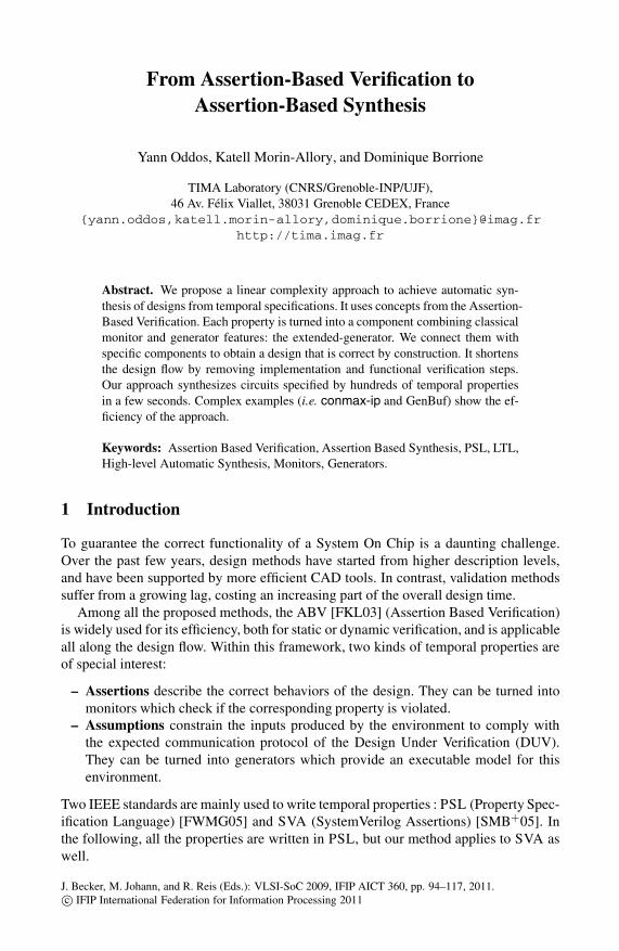
Figure 2 shows this retriggering of the property evaluation due to successive activa-tions of Start . Although not necessarily what one would expect, the trace of Figure 2also satisfies property P1.
We have developed the Horus project which aims at providing methodologies andtools for efficiently supporting property-based design all along the design flow. Withrespect to previous works and existing CAD software, Horus exhibits new and compet-itive advantages:
– The monitors and generators are built in a modular way, so that modules for sub-properties can be reused in more complex ones.
– The modular construction is very efficient: it takes a fraction of a second for dozensof complex properties.
– The method for building the monitors and the generators has been proven correctwith the PVS theorem prover [MAB06].
Another promising research domain is the automatic synthesis from temporal specifica-tions. It consists in automatically transforming a temporal specification into an HDL de-scription which is correct by construction. Figure 3 depicts a typical design flow where
96 Y. Oddos, K. Morin-Allory, and D. Borrione
Ack
Req
Start
1 2 3 4 5 6 7 8 9 121110
Fig. 2. Trace with several activations of Start
ANALYZERARCHITECT
Classic Design Flow
BACK−ENDDESIGNERDESIGNER
RTL
Natural
FormalLanguage
ASIC
FPGASimulationModel CheckingEq Checking
HDL code
VHDLVerilogSystemC
SpecificationWrite Functional
VerificationPrototyping/Fabrication
Write
Fig. 3. Design flow including the functional verification of a hand-coded RTL design
the hand-coded design has to be verified to guarantee that the realized functionnalitycomplies with the specification.
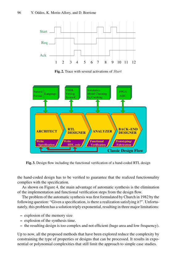
As shown on Figure 4, the main advantage of automatic synthesis is the eliminationof the implementation and functional verification steps from the design flow.
The problem of the automatic synthesis was first formulated by Church in 1982 by thefollowing question: “Given a specification, is there a realization satisfying it?”. Unfortu-nately, this problem has a solution triply exponential, resulting in three major limitations:
– explosion of the memory size– explosion of the synthesis time.– the resulting design is too complex and not efficient (huge area and low frequency).
Up to now, all the proposed methods that have been explored reduce the complexity byconstraining the type of properties or designs that can be processed. It results in expo-nential or polynomial complexities that still limit the approach to simple case studies.
From Assertion-Based Verification to Assertion-Based Synthesis 97
Automatic Synthesis−based Design Flow
ARCHITECTBACK−ENDDESIGNER
ASIC
FPGASimulationModel CheckingEq CheckingVerilog
VHDL
− SVA− PSL
Formal Languages
Prototyping/Fabrication
WriteSpecification
AUTOMATIC
SYNTHESIS
Produce Correct by ConstructionSynthesizable HDL Description
Fig. 4. Design flow with automatic synthesis of the RTL from formal properties
Whereas linear complexity approaches are available for Boolean specifications, nosuch methods exist for complex temporal specifications.
We use concepts of Assertion-Based Verification and the property synthesis approachdeveloped for Horus to define the method SyntHorus. It has a linear complexity ap-proach regarding the specification and automatically synthesizes a temporal specifica-tion written in PSLsimple into a correct by construction HDL description.
We turn assertions and assumptions into a new kind of hardware components mixingmonitors and generators: the extended-generators. They are the basic components of thesynthesized design and have been proved correct with respect to the PSL semantics.Combined with specific components called Solvers, the resulting circuit provides thefinal design corresponding to a given specification.
The SyntHorus tool can process complex specifications, composed with hundredsof properties, and produces the final circuit in a few seconds. The size of the circuit isproportional to the size of the specification.
2 State of the Art
2.1 Assertion-Based Verification
Many static verifiers, and the main commercial RTL simulators support PSL [CVK04].The European funded project “PROSYD” has published methodologies for the use ofPSL, and developed tools around PSL [PRO]. Notably, the RAT prototype, based onSAT and bounded model checking, helps verify property consistency [BCE+04].
The first industrial implementation of monitors is IBM FoCs [IBM]. The result ofFoCs is a cycle accurate simulation process that may be turned into a synthesizablecomponent with minor edition.
In the context of model checking, the usual technique translates a LTL formulainto a non-deterministic automaton that recognizes all the acceptable sequences of
98 Y. Oddos, K. Morin-Allory, and D. Borrione
values [DGV99,GO01]. The transformation into a deterministic automaton, needed fora hardware implementation, is exponential in the number of non-deterministic decisionstates [ST03]. A syntactically simple PSL formula can easily expand into a large LTLformula, so the direct automata theoretic approaches are too inefficient.
Moreover, due to the always operator, the monitors generated for on-line observa-tion must be retriggerable, and may be concurrently evaluating several instances of theproperty for several starting points in the sequence of signal values. When a propertyfails, for debug purposes, it is essential to identify the starting point of the subsequencethat caused the failure. The implementation principles for this feature have been de-scribed either in terms of control graphs with colored tokens [MAB07], or as a multi-plication of monitors [BCZ06]. A similar automata-based method [CRST06] is used inmodel checking.
Another aspect is the use of properties to specify constraints on the design environ-ment. Most industrial simulators provide software test vector generators based on thegeneration of constrained pseudo-random numbers [ABC+].
Among the static methods, Calame [Cal05] builds the product of the design automa-ton and the property automaton to extract test vectors that may lead to a wrong execu-tion. Another approach is based on slicing [YJC04]: the design is cut between registersto extract constraints and produce test vectors for each slice, which are then composedto get the test vector for the whole component. All these techniques are difficult to usedue to the complexity of their algorithms.
More efficient approaches rely on the property formulas, not the design under verifi-cation, to generate test vectors. The concept of ”cando objects” [SNBE07] is technicallyvery different, and oriented towards model checking rather than on-line execution; inparticular, they do not support arbitrary repetition (’+’ and ’*’) operators.
2.2 Automatic Synthesis from Specifications
A large body of research was devoted to the synthesis of combinatorial operators fromuntimed mathematical relations. We shall not discuss them, since the target of our workis the synthesis of control-type sequential circuits, where the successive occurrence ofevents is an essential aspect of the circuit behavior.
The specification of such sequences with regular expressions is not new [FU82,SB94]. These pioneer works use different kinds of BDDs (Free-BDDs and Reduced-Ordered BDDs respectively) to support the synthesis process. The use of BDD-basedalgorithms leads to the so called “state explosion problem” which confines the applica-tion to simple designs.
Other specification methods have been proposed, focusing on communication proto-cols. From BNF grammars, Oberg synthesizes controllers using a directed acyclic graphrepresentation [Obe99]. Alternatively, Muller [SM02] defined a dedicated SystemC li-brary to describe the specifications and uses automata-based methods to build the finaldesign.
Aziz et al. use logical S1S formulas (second order properties on naturals) to performautomatic synthesis of sequential designs [ABBSV00]. Despite the application of a
From Assertion-Based Verification to Assertion-Based Synthesis 99
variety of optimization techniques to reduce the complexity during the creation of thedesign, the automata-based approach cannot apply to complex designs.
Taking as input a specification in a standard assertion language is a more recentconcern. Bloem et al. [BGJ+07] defined a “Generalized Reactivity(1)” subset of PSLfrom which properties are translated to automata; game theory algorithms are appliedto compute all the correct behaviors of the design under all admissible interactions withthe environment. The method is more powerful than the preceding ones. It is polynomialin N3, where N is the sequential complexity of the specification.
Eveking et al. [SOSE08] aim at generating verification-friendly circuits. This methodtakes as input ITL, a proprietary dialect of interval temporal logic defined by OneSpinSolutions. It is similar to the PSL simple subset, limited to finite traces. In contrast toour approach, non deterministic behaviors assume additional inputs fed by an externalrandom source, and consistency is checked statically during the construction.
Our main objective is to quickly generate efficient circuits from complex sets ofproperties. Instead of using an automata based approach, or restricting the applicationto a specific type of designs, we use a modular construction. The complexity is thenencapsulated in different levels of basic components. The overall synthesis method wasproved to correctly generate circuits that comply with the PSL semantics.
3 Assertion-Based Verification
3.1 Monitors
A monitor is a synchronous design detecting dynamically all the violations of a giventemporal property. We detail here the last release of our approach used to synthesizeproperties into hardware monitors. It is based on the principles described in [MAB06].
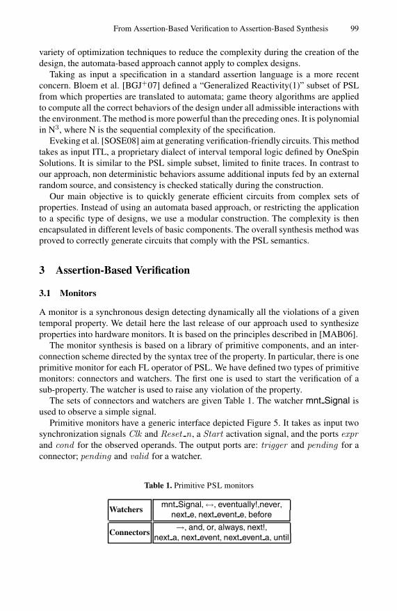
The monitor synthesis is based on a library of primitive components, and an inter-connection scheme directed by the syntax tree of the property. In particular, there is oneprimitive monitor for each FL operator of PSL. We have defined two types of primitivemonitors: connectors and watchers. The first one is used to start the verification of asub-property. The watcher is used to raise any violation of the property.
The sets of connectors and watchers are given Table 1. The watcher mnt Signal isused to observe a simple signal.
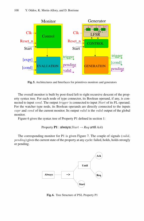
Primitive monitors have a generic interface depicted Figure 5. It takes as input twosynchronization signals Clk and Reset n , a Start activation signal, and the ports exprand cond for the observed operands. The output ports are: trigger and pending for aconnector; pending and valid for a watcher.
Table 1. Primitive PSL monitors
Watchersmnt Signal, ↔, eventually!,never,
next e, next event e, before
Connectors→, and, or, always, next!,
next a, next event, next event a, until
100 Y. Oddos, K. Morin-Allory, and D. Borrione
in1 in2
XOR
in3
LFSRClk
Start
GeneratorMonitor
Start
Reset_nReset_n
ClkControl
CONTROL
trigger
valid
pendingEVALUATION[cond]
[expr]
GENERATION
trigger
[cond]
pending
Fig. 5. Architectures and Interfaces for primitives monitors and generators
The overall monitor is built by post-fixed left to right recursive descent of the prop-erty syntax tree. For each node of type connector, its Boolean operand, if any, is con-nected to input cond . The output trigger is connected to input Start of its FL operand.For the watcher type node, its Boolean operands are directly connected to the inputsexpr and cond of the current monitor. Its output valid is the valid output of the globalmonitor.
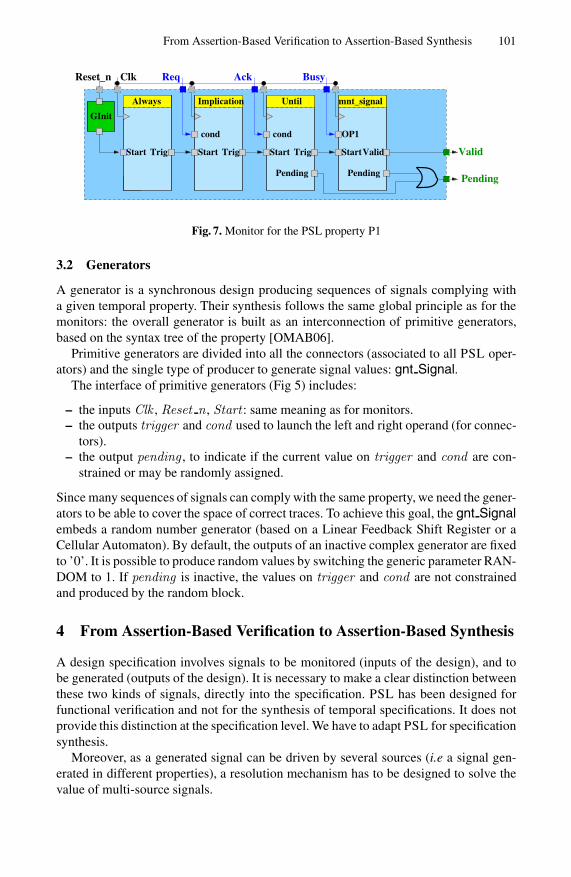
Figure 6 gives the syntax tree of Property P1 defined in section 1:
Property P1 : always(Start → Req until Ack)
The corresponding monitor for P1 is given Figure 7. The couple of signals (valid ,pending) gives the current state of the property at any cycle: failed, holds, holds stronglyor pending.
Start
−>Always
Until
Ack
Req
Fig. 6. Tree Structure of PSL Property P1
From Assertion-Based Verification to Assertion-Based Synthesis 101
GInit
TrigTrigStart
Clk
cond
Start TrigStart Start
OP1cond
Pending Pending Pending
ValidValid
Ack BusyReqReset_n
Always Implication Until mnt_signal
Fig. 7. Monitor for the PSL property P1
3.2 Generators
A generator is a synchronous design producing sequences of signals complying witha given temporal property. Their synthesis follows the same global principle as for themonitors: the overall generator is built as an interconnection of primitive generators,based on the syntax tree of the property [OMAB06].
Primitive generators are divided into all the connectors (associated to all PSL oper-ators) and the single type of producer to generate signal values: gnt Signal.
The interface of primitive generators (Fig 5) includes:
– the inputs Clk , Reset n , Start : same meaning as for monitors.– the outputs trigger and cond used to launch the left and right operand (for connec-
tors).– the output pending , to indicate if the current value on trigger and cond are con-
strained or may be randomly assigned.
Since many sequences of signals can comply with the same property, we need the gener-ators to be able to cover the space of correct traces. To achieve this goal, the gnt Signalembeds a random number generator (based on a Linear Feedback Shift Register or aCellular Automaton). By default, the outputs of an inactive complex generator are fixedto ’0’. It is possible to produce random values by switching the generic parameter RAN-DOM to 1. If pending is inactive, the values on trigger and cond are not constrainedand produced by the random block.
4 From Assertion-Based Verification to Assertion-Based Synthesis
A design specification involves signals to be monitored (inputs of the design), and tobe generated (outputs of the design). It is necessary to make a clear distinction betweenthese two kinds of signals, directly into the specification. PSL has been designed forfunctional verification and not for the synthesis of temporal specifications. It does notprovide this distinction at the specification level. We have to adapt PSL for specificationsynthesis.
Moreover, as a generated signal can be driven by several sources (i.e a signal gen-erated in different properties), a resolution mechanism has to be designed to solve thevalue of multi-source signals.
102 Y. Oddos, K. Morin-Allory, and D. Borrione
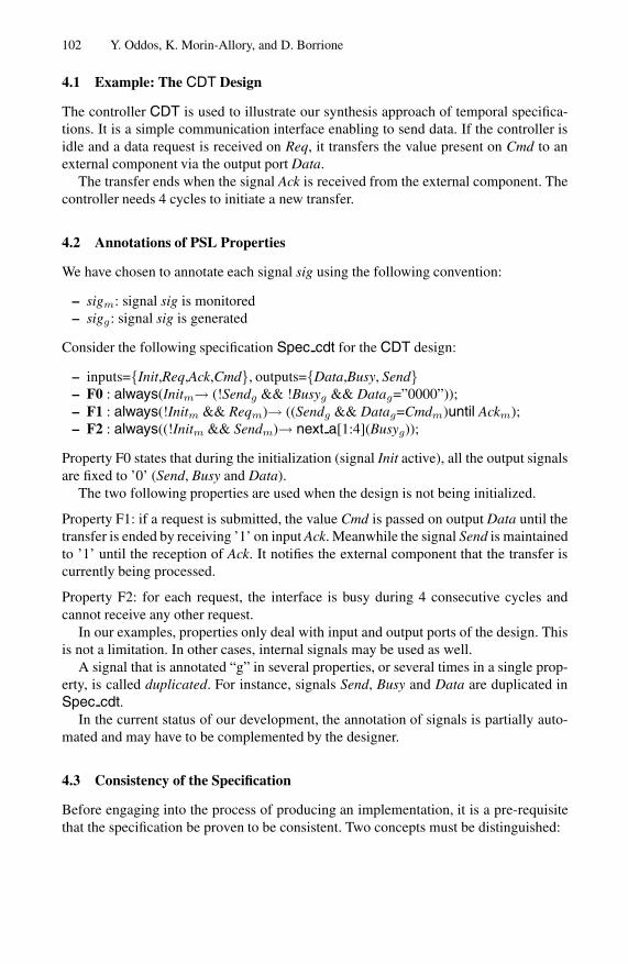
4.1 Example: The CDT Design
The controller CDT is used to illustrate our synthesis approach of temporal specifica-tions. It is a simple communication interface enabling to send data. If the controller isidle and a data request is received on Req, it transfers the value present on Cmd to anexternal component via the output port Data.
The transfer ends when the signal Ack is received from the external component. Thecontroller needs 4 cycles to initiate a new transfer.
4.2 Annotations of PSL Properties
We have chosen to annotate each signal sig using the following convention:
– sigm: signal sig is monitored– sigg: signal sig is generated
Consider the following specification Spec cdt for the CDT design:
– inputs={Init,Req,Ack,Cmd}, outputs={Data,Busy, Send}– F0 : always(Initm→ (!Sendg && !Busyg && Datag=”0000”));– F1 : always(!Initm && Reqm)→ ((Sendg && Datag=Cmdm)until Ackm);– F2 : always((!Initm && Sendm)→ next a[1:4](Busyg));
Property F0 states that during the initialization (signal Init active), all the output signalsare fixed to ’0’ (Send, Busy and Data).
The two following properties are used when the design is not being initialized.
Property F1: if a request is submitted, the value Cmd is passed on output Data until thetransfer is ended by receiving ’1’ on input Ack. Meanwhile the signal Send is maintainedto ’1’ until the reception of Ack. It notifies the external component that the transfer iscurrently being processed.
Property F2: for each request, the interface is busy during 4 consecutive cycles andcannot receive any other request.
In our examples, properties only deal with input and output ports of the design. Thisis not a limitation. In other cases, internal signals may be used as well.
A signal that is annotated “g” in several properties, or several times in a single prop-erty, is called duplicated. For instance, signals Send, Busy and Data are duplicated inSpec cdt.
In the current status of our development, the annotation of signals is partially auto-mated and may have to be complemented by the designer.
4.3 Consistency of the Specification
Before engaging into the process of producing an implementation, it is a pre-requisitethat the specification be proven to be consistent. Two concepts must be distinguished:
From Assertion-Based Verification to Assertion-Based Synthesis 103
Inconsistency. A set of properties is inconsistent if the set of value traces for which theyare satisfied is empty. As an example, the following two properties are inconsistent:
– assert always (am ∧ cg)– assert always (am ∧ !cg)
Tools such as RAT (Requirement Analysis Tool) [BCE+04] or the method on whichCando objects are built [SNBE07] detect inconsistencies statically.
We shall call consistent a set of properties such that, whatever the input combination,all the outputs always can be given a valid value.
Realizability. It may happen that one, two or more properties are satisfied under someconstraints on the input signals, and exhibit inconsistencies otherwise. Take the follow-ing example:
– assert always (am ⇒ cg)– assert always (bm ⇒ !cg)
If a and b have different values, the specification is realizable. But if signals a and b areboth active at a given cycle, c is constrained to contradictory values.
Overcoming this problem is done by adding assumptions to the specification. In theabove example, the following assumption is added: assume never (a and b).
Synthesizing the specification. In our approach, the specification is analyzed using RAT.Assume properties may be added in the process to produce realizable specifications.
Methods described in pre-existing works statically enumerate all the possible re-sponses of the design under all the possible actions of the environment, and hard-codeall the responses directly in the design. In contrast, our technique relies on the use ofspecial purpose “solver” components that compute the output values on the fly.
5 Assertion-Based Synthesis
5.1 The Extended-Generator
An extended-generator component is a combination of a monitor and a generator. Thebasic principle is to produce a predefined sequence of signals (generator part) when aspecial sequence is recognized (monitor part).
Primitive extended-generator. Only binary operators OPb can have both a monitoredand a generated operand. Such operator has two corresponding primitive extended-generators: OPbmg and OPbgm which respectively (monitor, generate) and (generate,monitor) the left and right operands.
We impose the following restriction for the PSL properties: a monitored operand ofan extended-generator must be Boolean. This limitation is just the adjustment of thePSL simple subset in the context of the extended-generators. To clarify the problemmet in the monitoring of an FL operand, consider the following example:
Property P2: (sigm → (next[4]Am) until Bg)
104 Y. Oddos, K. Morin-Allory, and D. Borrione
Assume that sig is ’1’ at cycle 0 and the production of signal B=’1’ is planned atcycle t. For all cycles j<t, the sub-property next[4]Am must be verified. The verificationwill complete at cycle t+3. It is then impossible to ensure at cycle t that the extended-generator always fulfills the corresponding property.
The monitoring of an FL property that requires a knowledge of the future to pro-duce signals at the present cycle is contrary to the principles of the PSL simple subset.Our restriction applies these principles in the new context introduced by the extended-generators, which combines the observation and generation concepts.
It follows that all the binary operators have at least one Boolean operand. This avoidsall the potential ambiguities concerning the choice of a primitive extended-generator(OPbmg or OPbgm). As an example, it is possible to use untilgm since the rightoperand is Boolean, but not untilmg as the left operand can be a FL property.
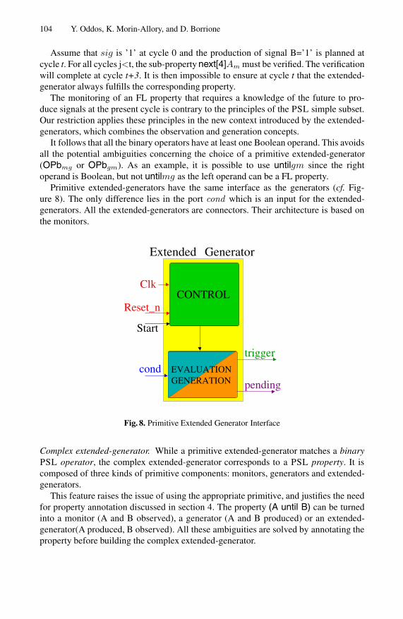
Primitive extended-generators have the same interface as the generators (cf. Fig-ure 8). The only difference lies in the port cond which is an input for the extended-generators. All the extended-generators are connectors. Their architecture is based onthe monitors.
Extended
Start
Clk
Reset_nCONTROL
pending
trigger
cond
Generator
GENERATIONEVALUATION
Fig. 8. Primitive Extended Generator Interface
Complex extended-generator. While a primitive extended-generator matches a binaryPSL operator, the complex extended-generator corresponds to a PSL property. It iscomposed of three kinds of primitive components: monitors, generators and extended-generators.
This feature raises the issue of using the appropriate primitive, and justifies the needfor property annotation discussed in section 4. The property (A until B) can be turnedinto a monitor (A and B observed), a generator (A and B produced) or an extended-generator(A produced, B observed). All these ambiguities are solved by annotating theproperty before building the complex extended-generator.
From Assertion-Based Verification to Assertion-Based Synthesis 105
A complex extended-generator has a generic interface taking as inputs the observedand synchronization signals, and providing on its outputs the generated and associatedpending signals.
Building the complex extended-generator is performed in two steps, based on thesyntax tree.
Step1 - Selection of primitive components: A node of the syntax tree that has gener-ators or extended-generators as operands is defined as a generator. If it has one operandof type generator and one of type monitor, it is an extended-generator. Two monitoredoperands produce a primitive monitor.
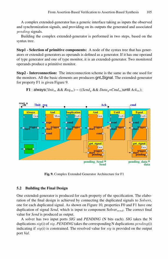
Step2 - Interconnection: The interconnection scheme is the same as the one used forthe monitors. All the basic elements are producers gnt Signal. The extended-generatorfor property F1 is given Figure 9.
F1 : always(!Initm && Reqm)→ ((Sendg && Datag=Cmdm)until Ackm);
expr cond cond
cond
clk !Init
cond
Gen ExtGExtGExtGMon
req
Gen
start
Gen
start
starttrigger
starttrigger trigger
start starttriggertrigger
start
trigger trigger
Ack cmd
cond
Gen
starttrigger
GInit
reset_n
dataSendpending_Send pending_data
pending pending
AndAlways Until EqualImplication
gnt_signal gnt_signal
And
Fig. 9. Complex Extended Generator Architecture for F1
5.2 Building the Final Design
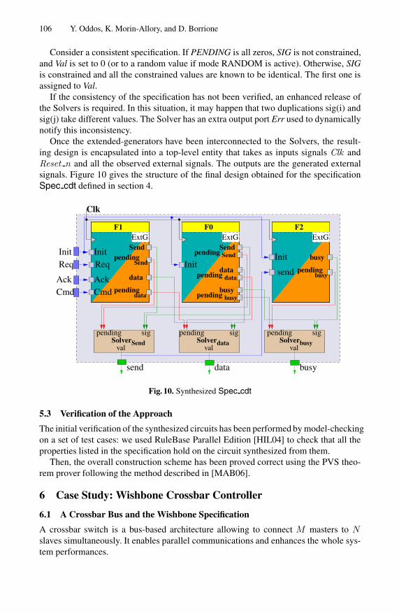
One extended-generator is produced for each property of the specification. The elabo-ration of the final design is achieved by connecting the duplicated signals to Solvers,one for each duplicated signal. As shown on Figure 10, properties F0 and F1 have oneduplication of signal Send, which is input to component Solversend. The correct finalvalue for Send is produced as output.
A solver has two input ports SIG and PENDING (N bits each). SIG takes the Nduplications sig(i) of sig . PENDING takes the corresponding N duplications pending(i)indicating if sig(i) is constrained. The resolved value for sig is provided on the outputport Val.
106 Y. Oddos, K. Morin-Allory, and D. Borrione
Consider a consistent specification. If PENDING is all zeros, SIG is not constrained,and Val is set to 0 (or to a random value if mode RANDOM is active). Otherwise, SIGis constrained and all the constrained values are known to be identical. The first one isassigned to Val.
If the consistency of the specification has not been verified, an enhanced release ofthe Solvers is required. In this situation, it may happen that two duplications sig(i) andsig(j) take different values. The Solver has an extra output port Err used to dynamicallynotify this inconsistency.
Once the extended-generators have been interconnected to the Solvers, the result-ing design is encapsulated into a top-level entity that takes as inputs signals Clk andReset n and all the observed external signals. The outputs are the generated externalsignals. Figure 10 gives the structure of the final design obtained for the specificationSpec cdt defined in section 4.
ExtGExtG ExtG
pending
Clk
pending pendingsig sig sig
F2F0F1
send
InitInit
send data busy
CmdAck
ReqInit
Solver SolverSolver
CmdAck
ReqInit Send
data
Send
data
busy
busy
busy
Send dataval
Send
data
pendingSend
datapending
pending
pending
pending
pendingbusy
busyval val
Fig. 10. Synthesized Spec cdt
5.3 Verification of the Approach
The initial verification of the synthesized circuits has been performed by model-checkingon a set of test cases: we used RuleBase Parallel Edition [HIL04] to check that all theproperties listed in the specification hold on the circuit synthesized from them.
Then, the overall construction scheme has been proved correct using the PVS theo-rem prover following the method described in [MAB06].
6 Case Study: Wishbone Crossbar Controller
6.1 A Crossbar Bus and the Wishbone Specification
A crossbar switch is a bus-based architecture allowing to connect M masters to Nslaves simultaneously. It enables parallel communications and enhances the whole sys-tem performances.
From Assertion-Based Verification to Assertion-Based Synthesis 107
In this chapter, we illustrate the application of Horus on a Wishbone compliant cross-bar [Her02]. The Wishbone specification defines a generic interface and a communi-cation protocol for the insertion of predefined IPs in a design. This context appearsparticularly appropriate for demonstrating the use of Horus.
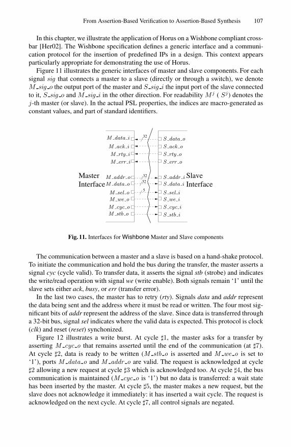
Figure 11 illustrates the generic interfaces of master and slave components. For eachsignal sig that connects a master to a slave (directly or through a switch), we denoteM sig o the output port of the master and S sig i the input port of the slave connectedto it, S sig o and M sig i in the other direction. For readability M j ( Sj) denotes thej-th master (or slave). In the actual PSL properties, the indices are macro-generated asconstant values, and part of standard identifiers.
InterfaceMaster
32
32
32
5
SlaveInterface
M cyc o
M we oM sel o
M data oM addr o
M stb o
S data o
S err o
S ack o
S rty o
M err i
M rty i
M ack i
M data i
S addr iS data i
S sel iS we i
S cyc i
S stb i
Fig. 11. Interfaces for Wishbone Master and Slave components
The communication between a master and a slave is based on a hand-shake protocol.To initiate the communication and hold the bus during the transfer, the master asserts asignal cyc (cycle valid). To transfer data, it asserts the signal stb (strobe) and indicatesthe write/read operation with signal we (write enable). Both signals remain ‘1’ until theslave sets either ack, busy, or err (transfer error).
In the last two cases, the master has to retry (rty). Signals data and addr representthe data being sent and the address where it must be read or written. The four most sig-nificant bits of addr represent the address of the slave. Since data is transferred througha 32-bit bus, signal sel indicates where the valid data is expected. This protocol is clock(clk) and reset (reset) synchonized.
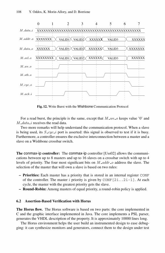
Figure 12 illustrates a write burst. At cycle �1, the master asks for a transfer byasserting M cyc o that remains asserted until the end of the communication (at �7).At cycle �2, data is ready to be written (M stb o is asserted and M we o is set to‘1’), ports M data o and M addr o are valid. The request is acknowledged at cycle�2 allowing a new request at cycle �3 which is acknowledged too. At cycle �4, the buscommunication is maintained (M cyc o is ‘1’) but no data is transferred: a wait statehas been inserted by the master. At cycle �5, the master makes a new request, but theslave does not acknowledge it immediately: it has inserted a wait cycle. The request isacknowledged on the next cycle. At cycle �7, all control signals are negated.
108 Y. Oddos, K. Morin-Allory, and D. Borrione
1 3 4 5 6 70 2
M ack i
M cyc o
M stb o
M we o
M sel o
M data o
M addr o
M data i
VALID3
VALID3
VALID3
VALID2
VALID2
VALID2
VALID1
VALID1
VALID1
XXXXXX
XXXXXX
XXXXXX
XXXXXXXXXXXXXX
XXXXXXX XXXXXX
XXXXXXX
XXXXXX
XXXXXXXXXXXXXXXXXXXXXXXXXXXXXXXXXXXXXXXXXXXXXXX
Fig. 12. Write Burst with the Wishbone Communication Protocol
For a read burst, the principle is the same, except that M we o keeps value ’0’ andM data i receives the read data.
Two more remarks will help understand the communication protocol. When a slaveis being used, its S cyc i port is asserted: this signal is observed to test if it is busy.Furthermore, a controller ensures the exclusive interconnection between a master and aslave on a Wishbone crossbar switch.
The conmax-ip controller: The conmax-ip controller [Uss02] allows the communi-cations between up to 8 masters and up to 16 slaves on a crossbar switch with up to 4levels of priority. The four most significant bits on M addr o address the slave. Theselection of the master that will own a slave is based on two rules:
– Priorities: Each master has a priority that is stored in an internal register CONFof the controller. The master i priority is given by CONF[2i..2i-1]. At eachcycle, the master with the greatest priority gets the slave.
– Round-Robin: Among masters of equal priority, a round-robin policy is applied.
6.2 Assertion-Based Verification with Horus
The Horus flow. The Horus software is based on two parts: the core implemented inC and the graphic interface implemented in Java. The core implements a PSL parser,generates the VHDL description of the property. It is approximately 10000 lines long.
The Horus environment helps the user build an instrumented design to ease debug-ging: it can synthesize monitors and generators, connect them to the design under test
From Assertion-Based Verification to Assertion-Based Synthesis 109
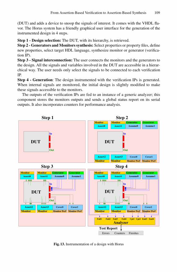
(DUT) and adds a device to snoop the signals of interest. It comes with the VHDL fla-vor. The Horus system has a friendly graphical user interface for the generation of theinstrumented design in 4 steps.
Step 1 - Design selection: The DUT, with its hierarchy, is retrieved.Step 2 - Generators and Monitors synthesis: Select properties or property files, definenew properties, select target HDL language, synthesize monitor or generator (verifica-tion IP).Step 3 - Signal interconnection: The user connects the monitors and the generators tothe design. All the signals and variables involved in the DUT are accessible in a hierar-chical way. The user needs only select the signals to be connected to each verificationIP.Step 4 - Generation: The design instrumented with the verification IPs is generated.When internal signals are monitored, the initial design is slightly modified to makethese signals accessible to the monitors.
The outputs of the verification IPs are fed to an instance of a generic analyzer; thiscomponent stores the monitors outputs and sends a global status report on its serialoutputs. It also incorporates counters for performance analysis.
Out
In
Analyzer
Out
In
Cpt1 Cpt2 End4End3Fail4Fail3Fail2Fail1
Out
In
Out
In
Step 3 Step 4
Step 2Step 1
FinishesCountersErrors
Test Report
DUTDUT
DUT DUT
Monitor
Monitor Monitor
Monitor Monitor
Monitor
Monitor
Generator
Monitor PerfMonitor Perf
Monitor Generator
Monitor
Monitor GeneratorGenerator
Monitor PerfMonitor Perf
Monitor GeneratorGenerator
Monitor PerfMonitor PerfMonitor
Assert0 Assert1
Assert0 Assert1
Assert1Assert0
Cover1Cover0 Cover1Cover0
Cover1Cover0
Assert3Assert2 Assert3Assert2
Assert2 Assert3
Assume1Assume0
Assume1Assume0
Assume1Assume0
Fig. 13. Instrumentation of a design with Horus
110 Y. Oddos, K. Morin-Allory, and D. Borrione
The instrumented design has a generic interface defined for an Avalon or a Wishbonebus. If the FPGA platform is based on such a bus, the user can directly synthesize andprototype the instrumented design on it.
Monitors: Many aspects of the conmax-ip have been verified with the Horus platform.A brief overview is given.
Property Reset Mj For all masters, signals M cyc o and M stb o must be negated aslong as Reset is asserted (c.f. [Her02], rule 3.20):
Property Reset Mj:assert always(Reset → (not M j cyc o and not M j stb o) untilnot Reset);
Property PrioMj Mk Assume two masters M j and Mk have priorities pj and pk suchthat pk > pj . If M j and Mk request the same slave simultaneously, Mk will own itfirst.
Property PrioMj Mk:assert always(M j cyc o and M k cyc oand CONF [2k..2k − 1] > CONF [2j..2j − 1]and M j addr o[0..3] = M k addr o[0..3])→ (M k ack i before M j ack i);
Property LinkMj Sk It checks the connection between the j-th master and k-th slave byanalyzing that each port is well connected.
Property LinkMj Sk:assert always(M j cyc o and S k cyc i and M j addr o = S k addr i)
→ (M j data o = S k data i and M j data i = S k data oand M j sel o = S k sel i and M j stb o = S k stb i
and M j we o = S k we i and M j ack i = S k ack o
and M j err i = S k err o and M j rty i = S k rty o);
Modelling the environment of the conmax-ip: To test the correctness of the conmax-ip controller in isolation, without the overhead of simulating a complete set of mastersand slaves, we need to embed the controller in an environment that provides correct testsignals. To this aim, we model masters and slaves with generators that must complywith the hand-shake protocol.
Property WriteMj Sk: A write request from the j-th master to the k-th slave is specifiedby the following property, to which a generator is associated:
Property WriteMj Sk:assume((M j cyc o and M j we o and M j sel o and M j stb oandM j data o = VAL DATA and M j addr o = VAL ADDR k)until M j ack i)
From Assertion-Based Verification to Assertion-Based Synthesis 111
Since we are interested in the communication action, but not in the particular datavalue being written, the value VAL DATA that is displayed on the port M i data o is arandomly computed constant. The four most significant bits of VAL ADDR are fixed toselect the j-th slave. This property is a simplified model of a master, it does not takeinto account signals M i rty i and M i err i (they are not mandatory). These signalswould be present in a more realistic model. This property involves the acknowledgmentinput signal M i ack i that stops the constrained generation.
Property GenLaunch. The scenarioGenLaunch illustrates the request of three mastersnumbered 0, 1, 2 to the same slave numbered 1. Master 0 first makes a request; then be-tween 16 to 32 cycles later, masters 1 and 2 simultaneously make their request. This sce-nario is modeled using a property that generates the start signals for three instancesof master generators (according to the previously discussed property), and one slave.These different start signals are denoted start WriteM0 S1, start WriteM1 S1,start WriteM2 S1.
assume eventually! (start WriteM0 S1→ next e[16..32](start WriteM1 S2 and start WriteM2 S2));
A large number of scenarios of various complexity have been written, and implementedwith generators, in order to have a realistic self-directed test environment. Modeling testscenarios for requests (i.e. read, burst, . . . ) is also performed with assumed properties,from which generators are produced.
For a slave, the most elaborate action is the response to a read request: signal S ack ois raised and the data is displayed on S data o. The following property expresses thisbehavior, at some initial (triggering) time.
assume next e[1..8](S j ack o and S j data o = DATA));
The generator for property Read Sj must be triggered each time the slave receivesa read request: its start signal is connected to the VHDL expression not S j we i andS j cyc i .
Performance analysis. Monitors can be used to perform measurements on the behaviorof the system. To this aim, the Horus platform is instrumented to analyze the monitoroutputs, and count the number of times when a monitor has been triggered, and thenumber of times when a failure has been found.
On the wishbone switch, and assuming that it is embedded in a real environment,it may be useful to test on line the number of times the signal M err i of a slave isasserted, or how often a slave is requested simultaneously by several masters.
Property CountError. The following property is used to count the number of transfersending with an error:
Property CountError: assert never (M 0 err i or . . . or M 7 err i);
Property ColliMj Sk. The property allows to know the number of times when morethan one master asks for the same slave:

112 Y. Oddos, K. Morin-Allory, and D. Borrione
Property ColliMj Sk: assert never (S j cyc i and S k cyc i and S j addr i =S k addr i);
6.3 Assertion-Based Synthesis with SyntHorus
SYNTHORUS The SyntHorus tool aims at providing an environment to support au-tomatic synthesis of HDL descriptions from PSL specifications, within the frameworkdescribed here. It represents 5000 lines of C source code and has been tested on a laptopequipped with a dual core processor and 2Go of RAM. The SyntHorus process flow isdepicted Figure 14.
a:1;b:5;data:32;...
Types
Spec
...
P1: always(P2: always(
P0 : always(
1
1
3
2 4
circuit5
Horus
SYNTHORUS
GeneratorsExtended
Fig. 14. The SyntHorus Tool
The idea consists in specifying control parts with PSL and synthesizing them withSyntHorus to guarantee their functionnality, while operative parts must be validatedwith other suitable methods.
SyntHorus takes as inputs the annotated specification file and a description for allthe signals involved in the specification (input, output, internal and type). It is inter-faced with HORUS, which produces the extended-generators. Afterwards SyntHorusinterconnects all these components, adding Solvers if necessary. Finally it encapsulatesthe result in a global enclosing component that constitutes synthesized design.
We fed SyntHorus with various complex specifications containing hundreds of prop-erties. For 700 properties, it produces an HDL description of 2,7 Mb within 16 seconds.
Synthesis Results. All syntheses have been done with Quartus7.0 for a CycloneIIEP2C35F672C6 FPGA-based platform. The synthesis optimization option “balanced”has been used.
CDT Synthesis. The annotation was complete for the Spec cdt specification.Table 2 gives the synthesis results for the CDT built by SyntHorus. The original
hand-coded design has 18 LCs, 6 FFs and a maximum frequency of 420Mhz. The designobtained from SyntHorus is slightly bigger than the original one.
In the following examples, we shall see that the efficiency of a SyntHorus design isgreatly affected by the number of embedded solvers.
From Assertion-Based Verification to Assertion-Based Synthesis 113
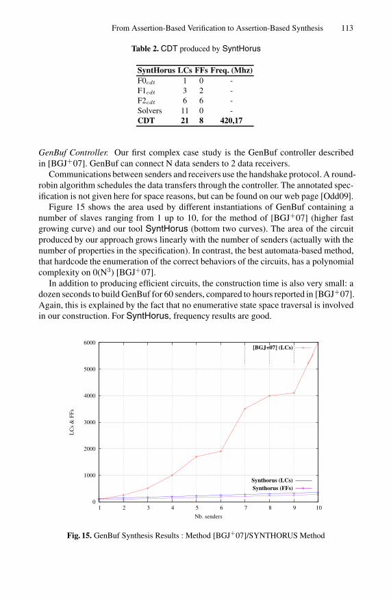
Table 2. CDT produced by SyntHorus
SyntHorus LCs FFs Freq. (Mhz)F0cdt 1 0 -F1cdt 3 2 -F2cdt 6 6 -Solvers 11 0 -CDT 21 8 420,17
GenBuf Controller. Our first complex case study is the GenBuf controller describedin [BGJ+07]. GenBuf can connect N data senders to 2 data receivers.
Communications between senders and receivers use the handshake protocol. A round-robin algorithm schedules the data transfers through the controller. The annotated spec-ification is not given here for space reasons, but can be found on our web page [Odd09].
Figure 15 shows the area used by different instantiations of GenBuf containing anumber of slaves ranging from 1 up to 10, for the method of [BGJ+07] (higher fastgrowing curve) and our tool SyntHorus (bottom two curves). The area of the circuitproduced by our approach grows linearly with the number of senders (actually with thenumber of properties in the specification). In contrast, the best automata-based method,that hardcode the enumeration of the correct behaviors of the circuits, has a polynomialcomplexity on 0(N3) [BGJ+07].
In addition to producing efficient circuits, the construction time is also very small: adozen seconds to build GenBuf for 60 senders, compared to hours reported in [BGJ+07].Again, this is explained by the fact that no enumerative state space traversal is involvedin our construction. For SyntHorus, frequency results are good.
0
1000
2000
3000
4000
5000
6000
1 2 3 4 5 6 7 8 9 10
LC
s &
FFs
Nb. senders
[11] (LCs)Synthorus (LCs)Synthorus (FFs)
[BGJ+07] (LCs)
Synthorus (FFs)Synthorus (LCs)
Fig. 15. GenBuf Synthesis Results : Method [BGJ+07]/SYNTHORUS Method
114 Y. Oddos, K. Morin-Allory, and D. Borrione
CONMAX-IP The conmax-ip annotated specification represents dozens of complextemporal properties. It can be found on the following web page [Odd09].
The following property Master1ToSlave2 is an example of the used properties:
Master1ToSlave2: assert always(((M1 cyc im and M1 addr im=”0010”) and(not(M0 cyc im) or M0 addr im/=”0010”) andnot(S2 cyc om))⇒ next[1]((
S2 addr og=M1 addr im and(S2 data og=M1 data imand S2 cyc og=M1 cyc im)and(S2 sel og=M1 sel im and S2 we og=M1 we im) and(S2 stb og=M1 stb im and M1 data og=S2 data im) and(M1 ack og=S2 ack im and M1 rty og=S2 rty im and M1 err og=S2 err im)until (M1 ack om or M1 rty om or M1 err oc)));
This property models the connection between the first master and the second slavewhen no other masters are trying to access the second slave. The connection is per-formed by connecting each port of the master to the corresponding port of the slaveinterface. The connection is maintained until the transfer is ended by the reception ofone of the three following signals: M1 ack om (transfer succeeded) or M1 rty om
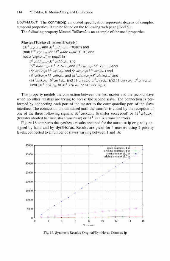
(transfer aborted because slave was busy) or M1 err oc (transfer error).Figure 16 compares the synthesis results obtained for the conmax-ip originally de-
signed by hand and by SyntHorus. Results are given for 4 masters using 2 prioritylevels, connected to a number of slaves varying between 1 and 16.
0
5000
10000
15000
20000
25000
30000
35000
40000
0 2 4 6 8 10 12 14 16
Nb. slaves
synth conmax (FFs)original conmax (FFs)
synth conmax (LCs)original conmax (LCs)
Fig. 16. Synthesis Results: Original/SyntHorus Conmax-ip
From Assertion-Based Verification to Assertion-Based Synthesis 115
LCs overhead is clearly visible and remains linear when the number of slaves in-creases. The main part of this overhead is due to the use of the Solvers. Notice that theFFs overhead is noticeably less important.
If the specification contains just a few duplicated signals, then the resulting designis efficient and its complexity is slightly higher than the same hand-coded design. Ifthere are lots of duplicated signals a significant overhead is introduced by SyntHorus.The designer should consider rewriting the specification to minimize the number ofduplications.
7 Conclusion
A method to efficiently synthesize a test-bench from temporal properties has been pre-sented. On one hand, the stimuli generation is carried out by hardware componentssynthesized from assumptions: the generators. On the other hand, monitors support theverification of the DUT behavior by on-line verifying that it complies with the corre-sponding assertions.
By annotating PSL signals and developing a new kind of hardware component calledextended-generator, we went beyond Assertion-Based Verification to produce a correct-by-construction module (at RTL) from its temporal specification. This “Assertion-BasedSynthesis” starts from a more abstract, formal and declarative specification than theconventional “High-level Synthesis” that takes as inputs an algorithmic specification.Assertion-Based Synthesis is best suited for control circuits.
The modularity of the approach encapsulates the high complexity of the specifica-tion into a hierarchy of verified components. The formal proof of the whole approachguarantees that the final circuit is correct by construction.
SyntHorus is a prototype tool that implements our Assertion-Based Synthesismethod. It takes as input PSL specifications and produces a RTL design in VHDL.To the best of our knowledge, ours is the first approach with a linear complexity, ableto process the full simple subset of PSL. Compared to the state of the art previous ap-proaches, the resulting designs are very efficient (i.e small and fast). Despite the fact thatthey are in general less efficient than the same hand coded designs, the automatically-synthesized designs can still be used as a golden model. Our method has a distinctadvantage: it can be used to produce a reference model, correct by construction, fromthe very first logic and temporal specifications. More efficient hand-coded designs canthen be proved correct, by conventional equivalence checking with the reference pro-duced by SyntHorus. Otherwise, the design produced by SyntHorus can be directlytaped-out.
Currently, annotating the specification is not fully automated. While it is obvious toannotate the input ports with “m”, output ports may occur as “m” and “g” in differentproperties (e.g. signal Send in Spec cdt). More work remains to be done to complementthe set of annotation rules we developed so far.

116 Y. Oddos, K. Morin-Allory, and D. Borrione
References
[ABBSV00] Aziz, A., Balarin, F., Brayton, R.-K., Sangiovanni-Vincentelli, A.-L.: Sequen-tial synthesis using S1S. IEEE Trans. on CAD of Integrated Circuits and Sys-tems 19(10), 1149–1162 (2000)
[ABC+] Anderson, T., Bergeron, J., Cerny, E., Hunter, A., Nightingale, A.: Systemverilogreference verification methodology: Introduction. EE Times, March 27 (2006)
[BCE+04] Bloem, R., Cavada, R., Eisner, C., Pill, I., Roveri, M., Semprini, S.: Manual forproperty simulation and assurance tool (deliverable 1.2/4-5). Technical report,PROSYD Project (January 2004)
[BCZ06] Boule, M., Chenard, J.-S., Zilic, Z.: Adding debug enhancements to assertioncheckers for hardware emulation and silicon debug. In: Proceedings of the 24thInternational Conference on Computer Design, ICCD 2006 (October 2006)
[BGJ+07] Bloem, R., Galler, S., Jobstman, B., Piterman, N., Pnueli, A., Weiglhofer, M.:Specify, compile, run: Hardware from PSL. Electronic Notes in Theoretical Com-puter Science (ENTCS) 190 (2007)
[Cal05] Calame, J.R.: Specification-based test generation with TGV. Technical ReportR0508, Centrum voor Wiskunde en Informatica (May 2005)
[CRST06] Cimatti, A., Roveri, M., Semprini, S., Tonetta, S.: From PSL to NBA: a Modu-lar Symbolic Encoding. In: Proceedings of IEEE Formal Methods for ComputerAided Design, FMCAD 2006, November 11-12, pp. 125–133 (2006)
[CVK04] Cohen, B., Venkataramanan, S., Kumari, A.: Using PSL/Sugar for Formal andDynamic Verification. VhdlCohen Publishing (2004)
[DGV99] Daniele, M., Giunchiglia, F., Vardi, M.: Improved Automata Generation for Lin-ear Temporal Logic. In: Halbwachs, N., Peled, D.A. (eds.) CAV 1999. LNCS,vol. 1633, pp. 249–260. Springer, Heidelberg (1999)
[FKL03] Foster, H., Krolnik, A., Lacey, D.: Assertion-Based Design. Kluwer AcademicPublishers, Dordrecht (2003)
[FU82] Floyd, R.-W., Ullman, J.D.: The compilation of regular expressions into integratedcircuits. J. ACM 29(3), 603–622 (1982)
[FWMG05] Foster, H., Wolfshal, Y., Marschner, E., IEEE 1850 Work Group: IEEE standardfor property specification language PSL. pub-IEEE-STD, pub-IEEE-STD:adr(October 2005)
[GO01] Gastin, P., Oddoux, D.: Fast LTL to Buchi automata translation. In: Berry, G.,Comon, H., Finkel, A. (eds.) CAV 2001. LNCS, vol. 2102, p. 53. Springer, Hei-delberg (2001)
[Her02] Herveille, R.: WISHBONE system-on-chip (SoC) interconnection architecturefor portable IP cores. Technical report (September 2002), http://www.opencores.org/projects.cgi/web/wishbone/wbspec_b3.pdf
[HIL04] Haifa-IBM-Laboratories. RuleBase Parallel Edition. IBM (November 2004)[IBM] IBM. PSL/Sugar-based Verification Tools. Web page, http://www.haifa.
il.ibm.com/projects/verification/sugar/tools.html[MAB06] Morin-Allory, K., Borrione, D.: Proven correct monitors from PSL specifications.
In: DATE 2006 (January 2006)[MAB07] Morin-Allory, K., Borrione, D.: On-line monitoring of properties built on regular
expressions sequences. In: Vachoux, A. (ed.) Applications of Specification andDesign Languages for SoCs. Springer, Heidelberg (2007)
[Obe99] Oberg, J.: ProGram: A Grammar-Based Method for Specification and HardwareSynthesis of Communication Protocols. PhD thesis, Royal Institue of Technolo-goy - Department of Electronics, Eletronic System Design, Sweden (1999)
From Assertion-Based Verification to Assertion-Based Synthesis 117
[Odd09] Oddos, Y.: PSL Specification for the WISHBONE Interconnect Matrix IP Core(2009), http://tima.imag.fr/vds/horus/synthorus_specs/
[OMAB06] Oddos, Y., Morin-Allory, K., Borrione, D.: On-line test vector generation fromtemporal constraints written in PSL. In: Proc. VLSI SoC 2006 (2006)
[PRO] PROSYD. Tools and techniques for property verification. Web page, http://www.prosyd.org/twiki/view/Public/DeliverablePageWP3
[SB94] Seawright, A., Brewer, F.: Clairvoyant: A synthesis system for production-basedspecification. IEEE Trans. on VLSI, 172–185 (June 1994)
[SM02] Siegmund, R., Muller, D.: Automatic synthesis of communication controller hard-ware from protocol specifications. IEEE Design & Test of Computers 19(4), 84–95 (2002)
[SMB+05] Srouji, J., Mehta, S., Brophy, D., Pieper, K., Sutherland, S., IEEE 1800 WorkGroup: IEEE Standard for SystemVerilog - Unified Hardware Design, Specifica-tion, and Verification Language. pub-IEEE-STD, pub-IEEE-STD:adr (November2005)
[SNBE07] Schickel, M., Nimbler, V., Braun, M., Eveking, H.: An Efficient Synthesis Methodfor Property-Based Design in Formal Verification: On Consistency and Com-pleteness of Property-Sets. In: Advances in Design and Specification Languagesfor Embedded Systems, pp. 179–196. Springer, Netherlands (2007), 978-1-4020-6149-3
[SOSE08] Schickel, M., Oberkonig, M., Schweikert, M., Eveking, H.: A case-study inproperty-based synthesis: Generating a cache controller from property-set. In:Villar, E. (ed.) Embedded Systems Specification and Design Languages, pp. 271–275. Springer, Netherlands (2008)
[ST03] Sebastiani, R., Tonetta, S.: More Deterministic vs Smaller Buchi Automata forEfficient LTL Model Checking. In: Geist, D., Tronci, E. (eds.) CHARME 2003.LNCS, vol. 2860, pp. 126–140. Springer, Heidelberg (2003)
[Uss02] Usselman, R.: WISHBONE Interconnect Matrix IP Core (2002), http://www.opencores.org/projects.cgi/web/wb_conmax/overview
[YJC04] Yen, C., Jou, J., Chen, K.: A divide-and-conquer-based algorithm for automaticsimulation vector generation. IEEE Design & Test of Computers 21(2), 111–120(2004)