FROG-A24-A24E 119AU35 v1 multi9 and use manuals issued with the automated system. Before ... opening...
14
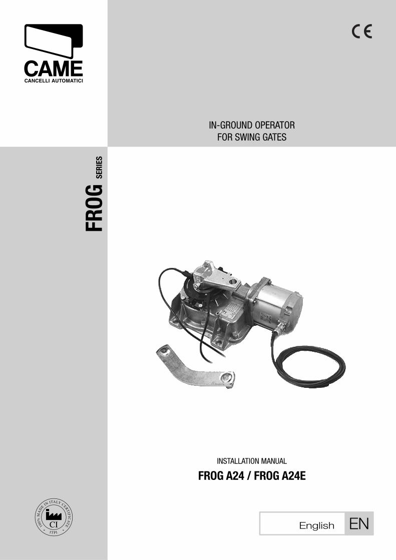
FROG SERIES INSTALLATION MANUAL FROG A24 / FROG A24E IN-GROUND OPERATOR FOR SWING GATES English EN
-
Upload
nguyenxuyen -
Category
Documents
-
view
216 -
download
0
Transcript of FROG-A24-A24E 119AU35 v1 multi9 and use manuals issued with the automated system. Before ... opening...
FR
OG
SERIE
S
INSTALLATION MANUAL FROG A24 / FROG A24E
IN-GROUND OPERATOR FOR SWING GATES
English EN
WARNING!Important instructions for the safety of people:
READ CAREFULLY!Foreword
• Use of the products must be restricted to its intended use (i.e. that for which it was expressly built for). Any other use is to be considered dangerous. Came Cancelli Automatici S.p.A. is not liable for any damage resulting from improper, wrongful or unreasonable use • Keep these warnings with the installa-tion and use manuals issued with the automated system.
Before installing (preliminary check: in case of a negative outcome, do not proceed before having
complied with the safety obligations)• Make sure that the parts you intend to automate are in good working order, and that they are properly balanced and aligned. Also, make sure that proper mechanical stops are already in place • If the operator will be installed at a height of less than 2.5 m from the ground or other access level, check whether you will need any protections and/or warnings • Any gate leaves, fi tted with pedestrian entrances, onto which you will install an operator, must have a blocking mechanism when the gate is in motion • Make sure that the opening of the automated gate is not an entrapment hazard as regards any surrounding fi xed parts • Do not mount the operator upside down or onto any elements that may fold under its weight. If needed, add suitable reinforcements at the points where it is secured • Do not install onto gates on either an upward or downward slope (i.e. that are not on fl at, level ground) • Check that any lawn watering devices will not wet the gearmotor from the bottom up.
Installation• Carefully section off the entire site to prevent unauthorised access, especially by minors and children • Be careful when handling operators that weigh more than 20 Kg (see installa-tion manual). In such cases, employ proper weight handling safety equipment • All opening commands (e.g. buttons, key selectors, magnetic detectors, etc.) must be installed at least 1.85 m from the gate’s area of operation perimeter - or where they cannot be reached from the outside of the gate. Also, the direct commands (e.g. push button, or proximity devices, etc.) must be installed at a height of at least 1.5 m and must not be accessible to the public • All ‘maintained action’ com-mands, must be placed where the moving gate leaves, transit areas and driveways are completely visible • If missing, ap-ply a permanent label that shows the position of the release mechanism • Before delivering to the client, verify that the system is EN 12453 (impact test) standard compliant. Make sure that the operator has been properly adjusted and that the safety and protection devices, as well as the manual release
are working properly • Where necessary and in plain sight, apply the Warning Sings (e.g. gate plate).
Special instructions and advice for users
• Keep the gate’s area of operation clean and clear of any obstacles. Trim any vegetation that may interfere with the photocells • Do not allow children to play with the fi xed com-mand devices, or in the gate’s area of operation. Keep any remote control devices (i.e. transmitters) away from the chil-dren as well • Frequently check the system, to see whether any anomalies or signs of wear and tear appear on the moving parts, on the component parts, on the securing points, on the cables and any accessible connections. Keep any joints (i.e. hinges) lubricated and clean, and do the same where fric-tion may occur (i.e. slide rails) • Perform functional tests on photocells and sensitive edges, every six months. Keep glass panels constantly clean (use a slightly water-moistened cloth; do not use solvents or any other chemical products) • If the system requires repairs or modifi cations, release the operator and do not use it until safety conditions have been restored • Cut off the power supply before releasing the operator for manual openings. See instructions • Users are FORBIDDEN to carry out ANY ACTIONS THAT THEY HAVE NOT BEEN EXPRESSLY ASKED TO DO OR SO INDICATED in the manu-als. Any repairs, modifi cations to the settings and extraor-dinary maintenance MUST BE DONE BY THE TECHNICAL ASSISTANCE STAFF • On the periodic maintenance log, note down the checks you have done.
Special instructions and advice for all
• Avoid working near the hinges or moving mechanical parts • Stay clear of the gate’s area of operation when in motion • Do not resist the direction of movement of the gate; this may present a safety hazard • At all times be extremely careful about dangerous points that must be indicated by proper pictograms and/or black and yellow stripes • When using a selector or command in ‘maintained action’ mode, keep checking that there are no people in the area of operation of the moving parts. Do this until you release the command • The gate may move at any time without warning • Always cut the power when cleaning performing maintenance.

THIS PAGE LEFT INTENTIONALLY BLANKTHIS PAGE LEFT INTENTIONALLY BLANK
Pag
. 2
-
Man
ual
cod
e: 1
19A
U3
511
9A
U3
5 v
er. 1.
01.
0 0
8/2
010
©
CA
ME
cance
lli a
utom
atic
i s.p
.a.
- Th
e dat
a an
d in
form
atio
n re
por
ted
in t
his
inst
alla
tion
man
ual
are
susc
eptib
le t
o ch
ange
at a
ny t
ime
and
with
out
oblig
atio
n on
CA
ME
cance
lli a
utom
atic
i s.p
.a.
to n
otify
use
rs.
EN
GLIS
H
4.1 Operator
4 Description
2.1 Intended use
1 Legend of symbols
This symbol tells you to read the section with particular care.
This symbol tells you that the sections concern safety issues.
This symbol tells you what to say to the end-users.
2 Condition of use
The FROG operator was engineered to power residential and condominium swing gates. The use of this product for purposes other than those described above and installation executed in a manner other than as
instructed in this technical manual are prohibited.
3 Reference Standards
“IMPORTANT INSTALLATION, SAFETY INSTRUCTIONS”
“CAUTION: IMPROPER INSTALLATION MAY CAUSE SERIOUS DAMAGE, FOLLOW ALL INSTALLATION INSTRUCTIONS CAREFULLY”
“THIS MANUAL IS ONLY FOR PROFESSIONAL OR QUALIFIED INSTALLERS”
2.2 Limits to use
This product is engineered and manufactured by CAME CANCELLI AUTOMATICI S.p.A. and complies with current safety regulations.The operator is made up of a foundation box, a release assembly, a gearmotor and a transmission arm.Zinc-plated press-forged fondation box for underground installation. On the inside is the release assembly with a customised, manual-release key and the gearmotor – made of a cast aluminium shell, inside of which operates an irreversible, gear-ratio and, endless screw plus helical crown system. A transmission arm is connected to the gearmotor.
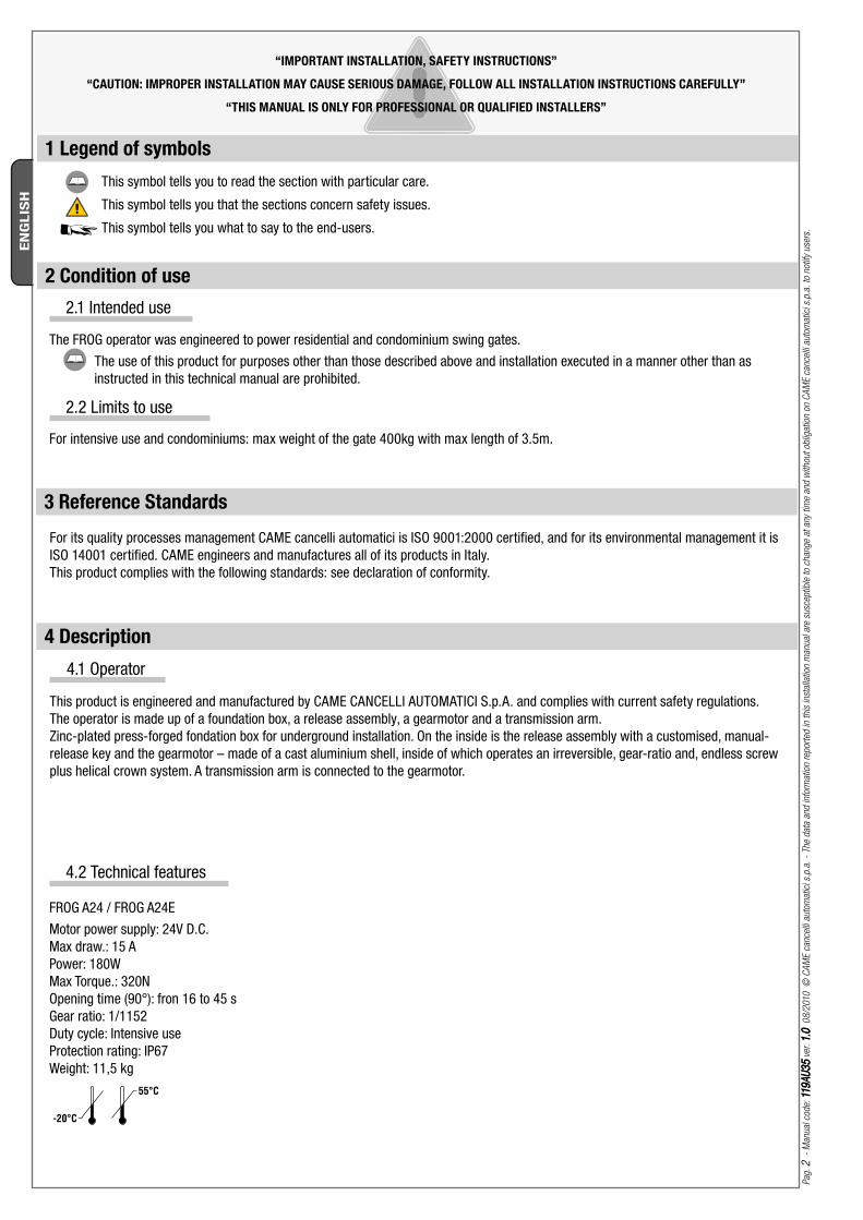
4.2 Technical features
FROG A24 / FROG A24E Motor power supply: 24V D.C. Max draw.: 15 A Power: 180WMax Torque.: 320NOpening time (90°): fron 16 to 45 sGear ratio: 1/1152Duty cycle: Intensive useProtection rating: IP67Weight: 11,5 kg
For intensive use and condominiums: max weight of the gate 400kg with max length of 3.5m.
For its quality processes management CAME cancelli automatici is ISO 9001:2000 certified, and for its environmental management it is ISO 14001 certified. CAME engineers and manufactures all of its products in Italy.This product complies with the following standards: see declaration of conformity.
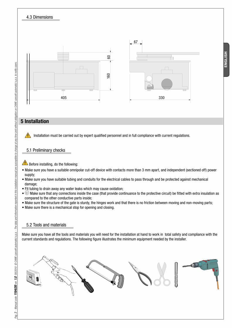
405 330
160
60
67
Pag
. 3
-
Man
ual
cod
e: 1
19A
U3
511
9A
U3
5 v
er. 1.
01.
0 0
8/2
010
©
CA
ME
cance
lli a
utom
atic
i s.p
.a.
- Th
e dat
a an
d in
form
atio
n re
por
ted
in t
his
inst
alla
tion
man
ual
are
susc
eptib
le t
o ch
ange
at a
ny t
ime
and
with
out
oblig
atio
n on
CA
ME
cance
lli a
utom
atic
i s.p
.a.
to n
otify
use
rs.
EN
GLIS
H
4.3 Dimensions
Make sure you have all the tools and materials you will need for the installation at hand to work in total safety and compliance with the current standards and regulations. The following figure illustrates the minimum equipment needed by the installer.
5.2 Tools and materials
5 Installation
Before installing, do the following:• Make sure you have a suitable omnipolar cut-off device with contacts more than 3 mm apart, and independent (sectioned off) power
supply;• Make sure you have suitable tubing and conduits for the electrical cables to pass through and be protected against mechanical
damage;• Fit tubing to drain away any water leaks which may cause oxidation;• Make sure that any connections inside the case (that provide continuance to the protective circuit) be fitted with extra insulation as
compared to the other conductive parts inside;• Make sure the structure of the gate is sturdy, the hinges work and that there is no friction between moving and non-moving parts;• Make sure there is a mechanical stop for opening and closing.
Installation must be carried out by expert qualified personnel and in full compliance with current regulations.
5.1 Preliminary checks
8 6
5
2 4
7
10 9
3
1
1
10
3
4x1,5
3x1,5
230V
4x1
2x1,5
RG58
3x1
5x1
2x1
4x1
RX
TX
RX
TX
4x1,5
2x1
11
Pag
. 4
-
Man
ual
cod
e: 1
19A
U3
511
9A
U3
5 v
er. 1.
01.
0 0
8/2
010
©
CA
ME
cance
lli a
utom
atic
i s.p
.a.
- Th
e dat
a an
d in
form
atio
n re
por
ted
in t
his
inst
alla
tion
man
ual
are
susc
eptib
le t
o ch
ange
at a
ny t
ime
and
with
out
oblig
atio
n on
CA
ME
cance
lli a
utom
atic
i s.p
.a.
to n
otify
use
rs.
EN
GLIS
H
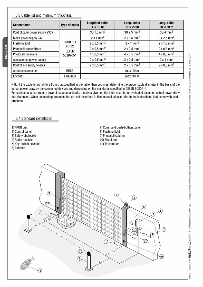
N.B.: If the cable length differs from that specified in the table, then you must determine the proper cable diameter in the basis of the actual power draw by the connected devices and depending on the standards specified in CEI EN 60204-1.For connections that require several, sequential loads, the sizes given on the table must be re-evaluated based on actual power draw and distances. When connecting products that are not described in this manual, please refer to the instructions that come with said products.
5.3 Cable list and minimum thickness
Connections Type of cableLength of cable
1 < 10 m
Leng. cable
10 < 20 m
Leng. cable
20 < 30 m
Control panel power supply 230V
FROR CEI 20-22 CEI EN
50267-2-1
3G 1,5 mm2 3G 2,5 mm2 3G 4 mm2
Motor power supply 24V 2 x 1 mm2 2 x 1,5 mm2 2 x 2,5 mm2
Flashing light 2 x 0,5 mm2 2 x 1 mm2 2 x 1,5 mm2
Photocell transmitters 2 x 0,5 mm2 2 x 0.5 mm2 2 x 0,5 mm2
Photocell receivers 4 x 0,5 mm2 4 x 0,5 mm2 4 x 0,5 mm2
Accessories power supply 2 x 0,5 mm2 2 x 0,5 mm2 2 x 1 mm2
Control and safety devices 2 x 0,5 mm2 2 x 0,5 mm2 2 x 0,5 mm2
Antenna connection RG58 max. 10 m
Encoder TWISTED max. 30 m
1) FROG unit 2) Control panel3) Safety photocells4) Radio receiver5) Key-switch selector6) Antenna
7) Command push-buthon panel8) Flashing light9) Photocell column10) Shunt box11) Transmitter
5.4 Standard installation
6767
160
100
60
3
Fig.2
Fig.3
Fig.4
DXSXFig.4-1 Fig.4-2
A
B
C C
B
A
SX DX
Pag
. 5
-
Man
ual
cod
e: 1
19A
U3
511
9A
U3
5 v
er. 1.
01.
0 0
8/2
010
©
CA
ME
cance
lli a
utom
atic
i s.p
.a.
- Th
e dat
a an
d in
form
atio
n re
por
ted
in t
his
inst
alla
tion
man
ual
are
susc
eptib
le t
o ch
ange
at a
ny t
ime
and
with
out
oblig
atio
n on
CA
ME
cance
lli a
utom
atic
i s.p
.a.
to n
otify
use
rs.
EN
GLIS
H
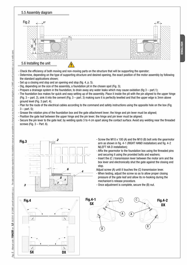
5.5 Assembly diagram
5.6 Installing the unit
- Check the effi ciency of both moving and non-moving parts on the structure that will be supporting the operator;- Determine, depending on the type of supporting structure and desired opening, the exact position of the motor assembly by following
the standard applications shown;- Set up a closing end stop and an opening end stop (fi g. 4, p. 5). - Dig, depending on the size of the assembly, a foundation pit in the chosen spot (Fig. 3);- Prepare a drainage system in the foundation, to drain away any water leaks which may cause oxidation (fi g 3 – part.1);- The foundation box makes for quick and easy setting up of the assembly. Place it inside the pit with the pin aligned to the upper hinge
(Fig. 3 – part. 2), sink it into the cement (Fig. 3 – part. 3) making sure it is perfectly levelled and that the upper edge is 3mm above ground level (Fig. 3 part. 4);
- Plan for the route of the electrical cables according to the command and safety instructions using the apposite hole on the box (Fig. 3 – part. 5);
- Grease the rotation pins of the foundation box and the gate attachment lever; the hinge and pin lever must be aligned;- Position the gate leaf between the upper hinge and the pin lever; the hinge and pin lever must be aligned;- Secure the pin lever to the gate leaf, by welding spots 3 to 4 cm apart along the contact surface. Avoid any welding near the threaded
screws (Fig. 3 – Part. 6).
- Screw the M10 x 100 (A) and the M10 (B) bolt onto the gearmotor arm as shown in fi g. 4-1 (RIGHT HAND installation) and fi g. 4-2 N(LEFT HA D installation);
- Affi x the gearmotor to the foundation box using the threaded pins and securing it using the provided bolts and washers;
- Insert the (C ) transmission lever between the motor arm and the box lever and electronically shut the gate against the closing end stop.
Adjust screw (A) until it touches the (C) transmission lever.- When testing, adjust the screw so as to allow proper closing
pressure of the gate leaf and allow its re-hooking during the mechanism’s release procedure.
- Once adjustment is complete, secure the (B) nut.
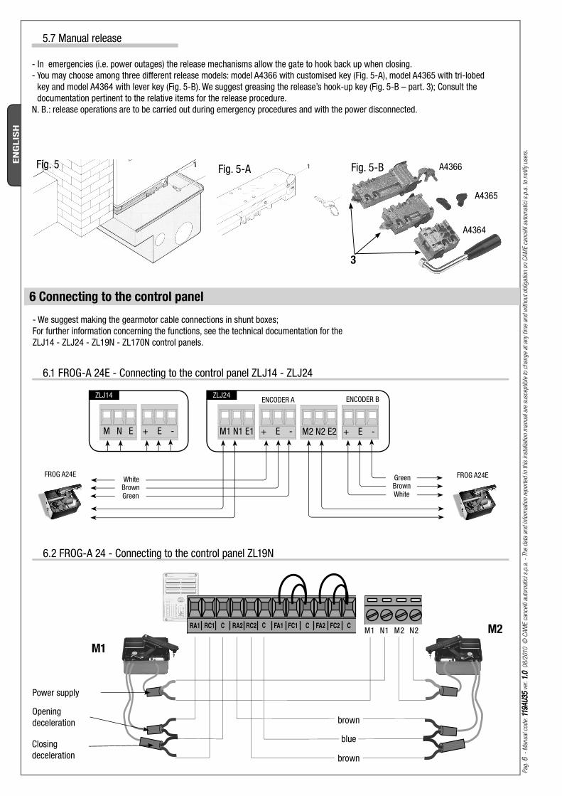
M1 N1 M2 N2
M1
M2
M1 N1 E1 + E - M2 N2 E2 + E -
FROG A24E
ENCODER BENCODER A
FROG A24E
3
Fig. 5 Fig. 5-A Fig. 5-B A4366
A4364
A4365
M N E + E -
ZLJ14 ZLJ24
Pag
. 6
-
Man
ual
cod
e: 1
19A
U3
511
9A
U3
5 v
er. 1.
01.
0 0
8/2
010
©
CA
ME
cance
lli a
utom
atic
i s.p
.a.
- Th
e dat
a an
d in
form
atio
n re
por
ted
in t
his
inst
alla
tion
man
ual
are
susc
eptib
le t
o ch
ange
at a
ny t
ime
and
with
out
oblig
atio
n on
CA
ME
cance
lli a
utom
atic
i s.p
.a.
to n
otify
use
rs.
EN
GLIS
H
- We suggest making the gearmotor cable connections in shunt boxes;For further information concerning the functions, see the technical documentation for the ZLJ14 - ZLJ24 - ZL19N - ZL170N control panels.
6 Connecting to the control panel
brown
brown
blue
Power supply
Opening deceleration
Closing deceleration
WhiteBrownGreen
GreenBrownWhite
5.7 Manual release
- In emergencies (i.e. power outages) the release mechanisms allow the gate to hook back up when closing.- You may choose among three diff erent release models: model A4366 with customised key (Fig. 5-A), model A4365 with tri-lobed
key and model A4364 with lever key (Fig. 5-B). We suggest greasing the release’s hook-up key (Fig. 5-B – part. 3); Consult the documentation pertinent to the relative items for the release procedure.
N. B.: release operations are to be carried out during emergency procedures and with the power disconnected.
6.2 FROG-A 24 - Connecting to the control panel ZL19N
6.1 FROG-A 24E - Connecting to the control panel ZLJ14 - ZLJ24
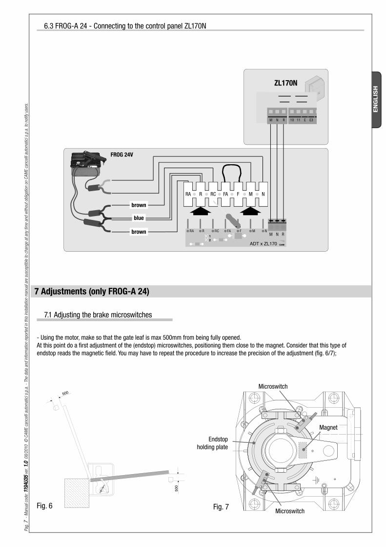
Fig. 7Fig. 6
12
RA R RC FA F M NM N R
ADT x ZL170
FROG 24V
ZL170N
M N R 10 11 E E3
Pag
. 7
-
Man
ual
cod
e: 1
19A
U3
511
9A
U3
5 v
er. 1.
01.
0 0
8/2
010
©
CA
ME
cance
lli a
utom
atic
i s.p
.a.
- Th
e dat
a an
d in
form
atio
n re
por
ted
in t
his
inst
alla
tion
man
ual
are
susc
eptib
le t
o ch
ange
at a
ny t
ime
and
with
out
oblig
atio
n on
CA
ME
cance
lli a
utom
atic
i s.p
.a.
to n
otify
use
rs.
EN
GLIS
H
brown
blue
brown
7.1 Adjusting the brake microswitches
- Using the motor, make so that the gate leaf is max 500mm from being fully opened. At this point do a fi rst adjustment of the (endstop) microswitches, positioning them close to the magnet. Consider that this type of endstop reads the magnetic fi eld. You may have to repeat the procedure to increase the precision of the adjustment (fi g. 6/7);
Microswitch
Endstop holding plate
Magnet
Microswitch
7 Adjustments (only FROG-A 24)
6.3 FROG-A 24 - Connecting to the control panel ZL170N
Pag
. 8
-
Man
ual
cod
e: 1
19A
U3
511
9A
U3
5 v
er. 1.
01.
0 0
8/2
010
©
CA
ME
cance
lli a
utom
atic
i s.p
.a.
- Th
e dat
a an
d in
form
atio
n re
por
ted
in t
his
inst
alla
tion
man
ual
are
susc
eptib
le t
o ch
ange
at a
ny t
ime
and
with
out
oblig
atio
n on
CA
ME
cance
lli a
utom
atic
i s.p
.a.
to n
otify
use
rs.
EN
GLIS
H
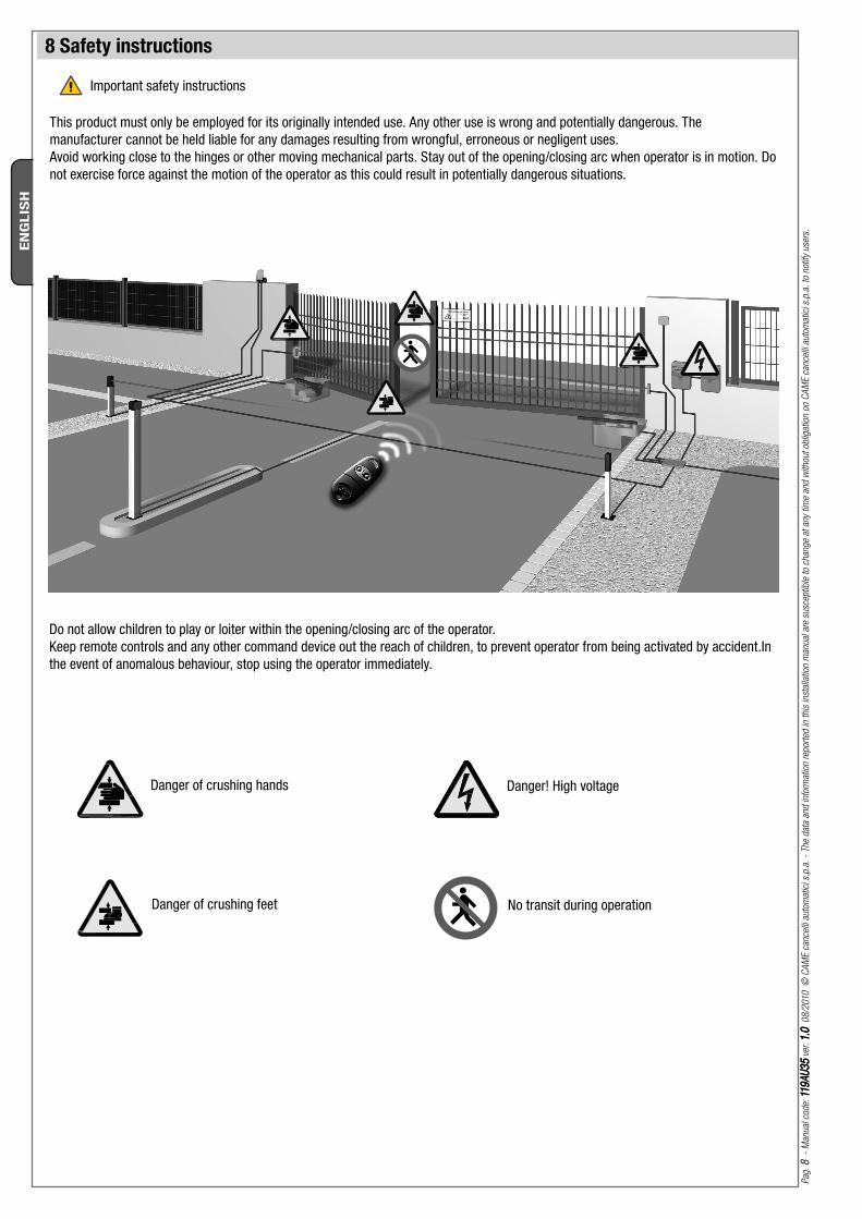
8 Safety instructions
This product must only be employed for its originally intended use. Any other use is wrong and potentially dangerous. The manufacturer cannot be held liable for any damages resulting from wrongful, erroneous or negligent uses.Avoid working close to the hinges or other moving mechanical parts. Stay out of the opening/closing arc when operator is in motion. Do not exercise force against the motion of the operator as this could result in potentially dangerous situations.
Do not allow children to play or loiter within the opening/closing arc of the operator.Keep remote controls and any other command device out the reach of children, to prevent operator from being activated by accident.In the event of anomalous behaviour, stop using the operator immediately.
Danger of crushing hands
Danger of crushing feet
Danger! High voltage
No transit during operation
Important safety instructions
Pag
. 9
-
Man
ual
cod
e: 1
19A
U3
511
9A
U3
5 v
er. 1.
01.
0 0
8/2
010
©
CA
ME
cance
lli a
utom
atic
i s.p
.a.
- Th
e dat
a an
d in
form
atio
n re
por
ted
in t
his
inst
alla
tion
man
ual
are
susc
eptib
le t
o ch
ange
at a
ny t
ime
and
with
out
oblig
atio
n on
CA
ME
cance
lli a
utom
atic
i s.p
.a.
to n
otify
use
rs.
EN
GLIS
H
9 Maintenance
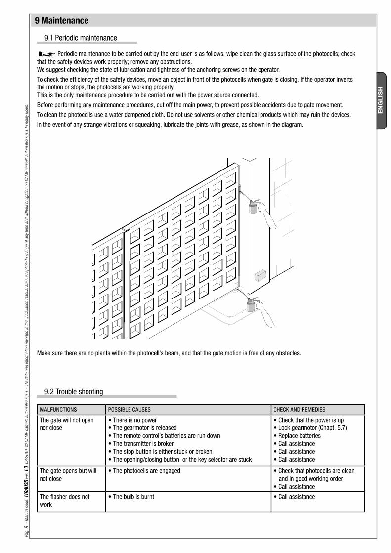
9.1 Periodic maintenance
Periodic maintenance to be carried out by the end-user is as follows: wipe clean the glass surface of the photocells; check that the safety devices work properly; remove any obstructions.We suggest checking the state of lubrication and tightness of the anchoring screws on the operator.To check the efficiency of the safety devices, move an object in front of the photocells when gate is closing. If the operator inverts the motion or stops, the photocells are working properly.This is the only maintenance procedure to be carried out with the power source connected.Before performing any maintenance procedures, cut off the main power, to prevent possible accidents due to gate movement.To clean the photocells use a water dampened cloth. Do not use solvents or other chemical products which may ruin the devices.In the event of any strange vibrations or squeaking, lubricate the joints with grease, as shown in the diagram.
Make sure there are no plants within the photocell’s beam, and that the gate motion is free of any obstacles.
9.2 Trouble shooting
MALFUNCTIONS POSSIBLE CAUSES CHECK AND REMEDIES
The gate will not open nor close
• There is no power• The gearmotor is released• The remote control’s batteries are run down• The transmitter is broken• The stop button is either stuck or broken• The opening/closing button or the key selector are stuck
• Check that the power is up• Lock gearmotor (Chapt. 5.7)• Replace batteries• Call assistance• Call assistance• Call assistance
The gate opens but will not close
• The photocells are engaged • Check that photocells are clean and in good working order
• Call assistance
The flasher does not work
• The bulb is burnt • Call assistance
Pag
. 1010
-
Man
ual
cod
e: 1
19A
U3
511
9A
U3
5 v
er. 1.
01.
0 0
8/2
010
©
CA
ME
cance
lli a
utom
atic
i s.p
.a.
- Th
e dat
a an
d in
form
atio
n re
por
ted
in t
his
inst
alla
tion
man
ual
are
susc
eptib
le t
o ch
ange
at a
ny t
ime
and
with
out
oblig
atio
n on
CA
ME
cance
lli a
utom
atic
i s.p
.a.
to n
otify
use
rs.
EN
GLIS
H
9.3 Extra-ordinary maintenance
The following table serves to note down any extraordinary maintenance, repairs or improvements performed by specialised firms. N.B.: Any extraordinary maintenance must be performed by specialised technicians.
Extra-ordinary maintenance log
Date Notes Segnature
Periodic maintenance log (for end-user) (every 6 moths)
Installer’s stamp Operator name
Date of job
Technician’s segnature
Requester’s segnature
Job performed _________________________________________________________________________________________________________________________________________________________________________________________
Installer’s stamp Operator name
Date of job
Technician’s segnature
Requester’s segnature
Job performed _________________________________________________________________________________________________________________________________________________________________________________________
Installer’s stamp Operator name
Date of job
Technician’s segnature
Requester’s segnature
Job performed _________________________________________________________________________________________________________________________________________________________________________________________
Pag
. 1111
-
Man
ual
cod
e: 1
19A
U3
511
9A
U3
5 v
er. 1.
01.
0 0
8/2
010
©
CA
ME
cance
lli a
utom
atic
i s.p
.a.
- Th
e dat
a an
d in
form
atio
n re
por
ted
in t
his
inst
alla
tion
man
ual
are
susc
eptib
le t
o ch
ange
at a
ny t
ime
and
with
out
oblig
atio
n on
CA
ME
cance
lli a
utom
atic
i s.p
.a.
to n
otify
use
rs.
EN
GLIS
H
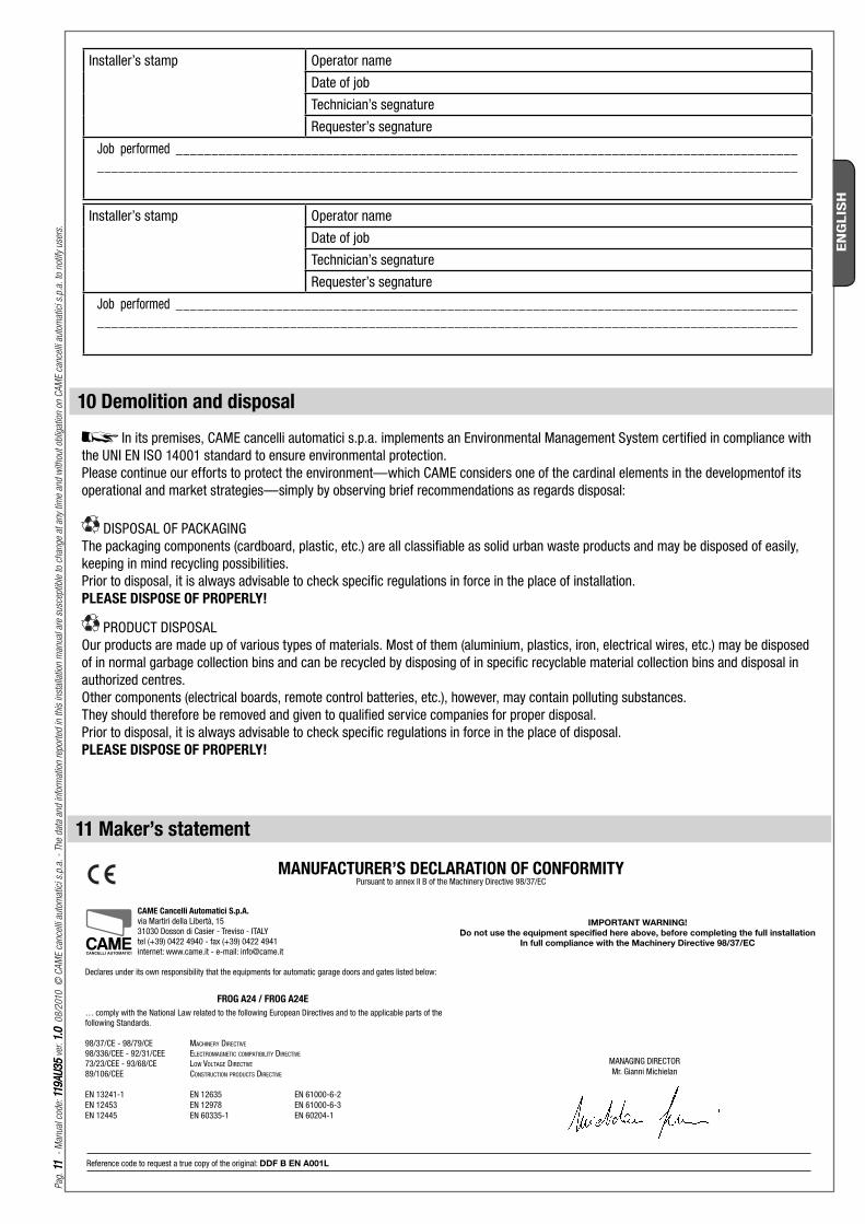
10 Demolition and disposal
MANUFACTURER’S DECLARATION OF CONFORMITYPursuant to annex II B of the Machinery Directive 98/37/EC
CAME Cancelli Automatici S.p.A.
via Martiri della Libertà, 15 31030 Dosson di Casier - Treviso - ITALY tel (+39) 0422 4940 - fax (+39) 0422 4941 internet: www.came.it - e-mail: [email protected]
Declares under its own responsibility that the equipments for automatic garage doors and gates listed below:
… comply with the National Law related to the following European Directives and to the applicable parts of the following Standards.
98/37/CE - 98/79/CE MACHINERY DIRECTIVE
98/336/CEE - 92/31/CEE ELECTROMAGNETIC COMPATIBILITY DIRECTIVE
73/23/CEE - 93/68/CE LOW VOLTAGE DIRECTIVE
89/106/CEE CONSTRUCTION PRODUCTS DIRECTIVE
EN 13241-1 EN 12635 EN 61000-6-2 EN 12453 EN 12978 EN 61000-6-3 EN 12445 EN 60335-1 EN 60204-1
FROG A24 / FROG A24E
11 Maker’s statement
Reference code to request a true copy of the original: DDF B EN A001L
Installer’s stamp Operator name
Date of job
Technician’s segnature
Requester’s segnature
Job performed _________________________________________________________________________________________________________________________________________________________________________________________
Installer’s stamp Operator name
Date of job
Technician’s segnature
Requester’s segnature
Job performed _________________________________________________________________________________________________________________________________________________________________________________________
In its premises, CAME cancelli automatici s.p.a. implements an Environmental Management System certified in compliance with the UNI EN ISO 14001 standard to ensure environmental protection.Please continue our efforts to protect the environment—which CAME considers one of the cardinal elements in the developmentof its operational and market strategies—simply by observing brief recommendations as regards disposal:
DISPOSAL OF PACKAGINGThe packaging components (cardboard, plastic, etc.) are all classifiable as solid urban waste products and may be disposed of easily, keeping in mind recycling possibilities.Prior to disposal, it is always advisable to check specific regulations in force in the place of installation.PLEASE DISPOSE OF PROPERLY!
PRODUCT DISPOSALOur products are made up of various types of materials. Most of them (aluminium, plastics, iron, electrical wires, etc.) may be disposed of in normal garbage collection bins and can be recycled by disposing of in specific recyclable material collection bins and disposal in authorized centres. Other components (electrical boards, remote control batteries, etc.), however, may contain polluting substances. They should therefore be removed and given to qualified service companies for proper disposal.Prior to disposal, it is always advisable to check specific regulations in force in the place of disposal.PLEASE DISPOSE OF PROPERLY!
IMPORTANT WARNING!
Do not use the equipment specifi ed here above, before completing the full installation
In full compliance with the Machinery Directive 98/37/EC
MANAGING DIRECTORMr. Gianni Michielan
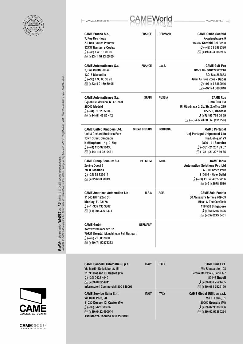
CAMECAME FranceFrance S.a. S.a. FRANCE7, Rue Des HarasZ.i. Des Hautes Patures92737 Nanterre CedexNanterre Cedex
(+33) 1 46 13 05 05 (+33) 1 46 13 05 00
GERMANY CAME Gmbh Seefeld CAME Gmbh SeefeldAkazienstrasse, 9
16356 Seefeld Seefeld Bei Berlin (+49) 33 3988390
(+49) 33 39883985
CAME Automatismes S.a. CAME Automatismes S.a. FRANCE3, Rue Odette Jasse13015 MarseilleMarseille
(+33) 4 95 06 33 70 (+33) 4 91 60 69 05
U.A.E. CAME Gulf Fze CAME Gulf FzeOffi ce No: S10122a2o210
P.O. Box 262853 Jebel Ali Free Zone - Dubai Dubai
(+971) 4 8860046 (+971) 4 8860048
CAME Automatismos S.a. CAME Automatismos S.a. SPAINC/juan De Mariana, N. 17-local28045 Madrid Madrid
(+34) 91 52 85 009 (+34) 91 46 85 442
RUSSIA CAME Rus CAME RusUmc Rus LlcUmc Rus Llc
Ul. Otradnaya D. 2b, Str. 2, offi ce 219 127273, MoscowMoscow
(+7) 495 739 00 69 (+7) 495 739 00 69 (ext. 226)
CAME United Kingdom Ltd. CAME United Kingdom Ltd. GREAT BRITAINUnit 3 Orchard Business ParkTown Street, SandiacreNottingham Nottingham - Ng10 5bp
(+44) 115 9210430 (+44) 115 9210431
PORTUGAL CAME Portugal CAME Portugal Ucj Portugal Unipessoal LdaUcj Portugal Unipessoal Lda
Rua Liebig, nº 23 2830-141 BarreiroBarreiro
(+351) 21 207 39 67 (+351) 21 207 39 65
CAME Group Benelux S.a. CAME Group Benelux S.a. BELGIUMZoning Ouest 77860 Lessines Lessines
(+32) 68 333014 (+32) 68 338019
INDIA CAME India CAME India Automation Solutions Pvt. LtdAutomation Solutions Pvt. Ltd
A - 10, Green Park 110016 - New DelhiNew Delhi
(+91) 11 64640255/256 (+91) 2678 3510
CAME Americas Automation Llc CAME Americas Automation Llc U.S.A11345 NW 122nd St. MedleyMedley, FL 33178
(+1) 305 433 3307 (+1) 305 396 3331
ASIA CAME Asia Pacific CAME Asia Pacific 60 Alexandra Terrace #09-09
Block C, The ComTech118 502 SingaporeSingapore
(+65) 6275 8426 (+65) 6275 5451
CAME Gmbh CAME Gmbh GERMANYKornwestheimer Str. 3770825 Korntal Korntal Munchingen Bei Stuttgart
(+49) 71 5037830 (+49) 71 50378383
CAME Cancelli Automatici S.p.a. CAME Cancelli Automatici S.p.a. ITALYVia Martiri Della Libertà, 1531030 Dosson Di Casier Dosson Di Casier (Tv)
(+39) 0422 4940 (+39) 0422 4941
Informazioni Commerciali 800 848095
ITALY CAME Sud s.r.l.CAME Sud s.r.l.Via F. Imparato, 198
Centro Mercato 2, Lotto A/7 80146 Napoli Napoli
(+39) 081 7524455 (+39) 081 7529190
CAME Service Italia S.r.l. CAME Service Italia S.r.l. ITALYVia Della Pace, 2831030 Dosson Di Casier Dosson Di Casier (Tv)
(+39) 0422 383532 (+39) 0422 490044
Assistenza Tecnica 800 295830Assistenza Tecnica 800 295830
ITALY CAME Global Utilities s.r.l.CAME Global Utilities s.r.l.Via E. Fermi, 31
20060 GessateGessate (Mi) (+39) 02 95380366 (+39) 02 95380224
05_2010
www.came.com www.came.it
En
glish
En
glish
-
Man
ual
cod
e: 1
19
AU
35
119
AU
35
ver
. 1
.01
.0 0
8/2
010
© C
AM
E ca
nce
lli a
utom
atic
i s.p
.a.
The
dat
a an
d in
form
atio
n re
por
ted
in t
his
inst
alla
tion
man
ual
are
susc
eptib
le t
o ch
ange
at a
ny t
ime
and
with
out
oblig
atio
n on
CA
ME
cance
lli a
utom
atic
i s.p
.a.
to n
otify
use
rs.