Fritted glass task group Spring 2017 - c.ymcdn.comc.ymcdn.com/sites/ · Fritted glass task group...
39
Fritted glass task group Spring 2017 Jacob C. Jonsson Windows and Envelope Materials Group Building Technology and Urban Systems Division
Transcript of Fritted glass task group Spring 2017 - c.ymcdn.comc.ymcdn.com/sites/ · Fritted glass task group...

Fritted glass task group Spring 2017
Jacob C. Jonsson
Windows and Envelope Materials Group
Building Technology and Urban Systems Division
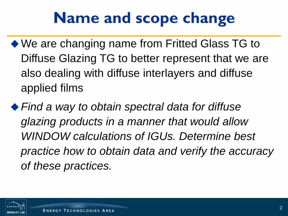
Name and scope change We are changing name from Fritted Glass TG to
Diffuse Glazing TG to better represent that we are also dealing with diffuse interlayers and diffuse applied films
Find a way to obtain spectral data for diffuse glazing products in a manner that would allow WINDOW calculations of IGUs. Determine best practice how to obtain data and verify the accuracy of these practices.
2

Outline for today’s session Presentation of progress regarding 270 mm
spheres with 100 mm apertures
Plan for future work
Presentation of ballot work regarding to 300-series documents (full discussion of ballots scheduled for the afternoon so I will try to breeze through what we did and spend more time on what we wanted to do)
Discussion based presentation, interrupt with questions and comments as you see fit
3

Determine best practice how to obtain data
First step was to find a set of measurements we can use as gold standard
Four instruments Guardian 270 mm sphere with 100/50 mm aperture LBNL pgII goniophotometer Fraunhofer ISE pgII goniophotometer Fraunhofer 630 mm sphere with wide area illumination
Viracon made a laminate for each of the 3 labs 12 mm OptiWhite (low iron)+0.030“ Saflex Arctic Snow
(transluscent white)PVB+3 mm Optiwhite float glass Guardian got all 3 samples to see how identical they were
4
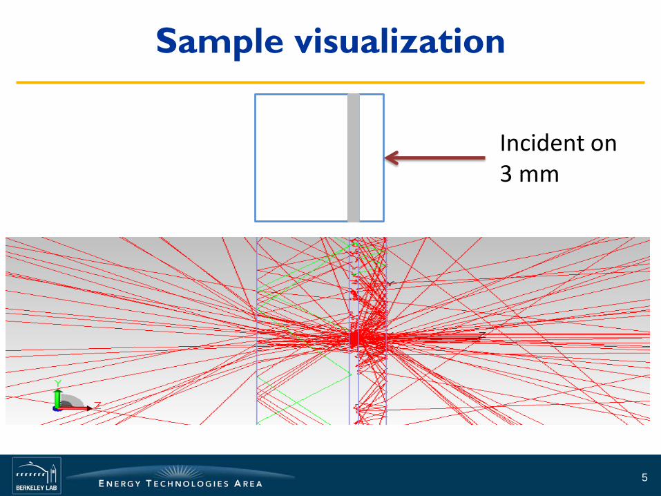
Sample visualization
5
Incident on 3 mm

Measurement problem Light not entering the
integrating sphere is a systematic error
Sample dependent • Bulk/surface scattering • Thickness
Instrument dependent • Detector response vs
angle of incidence • Sphere geometry
6

Measurement problem Aperture
studies made by OMT is the fundamental test that informs this design
7

Different ways to measure transmittance using 150 mm sphere
Standard port
Front Side1 2 3 1 3
Front Side
Large port Small aperture
0 1 3Front Side
1. Sample, here a fritted glass with the fritted side towards the sphere
2. Standard Labsphere port plate, easy to remove
3. Part of the sphere
0. Aperture plate (not included by Labsphere) to reduce beam size

V175 transmittance - 6 results
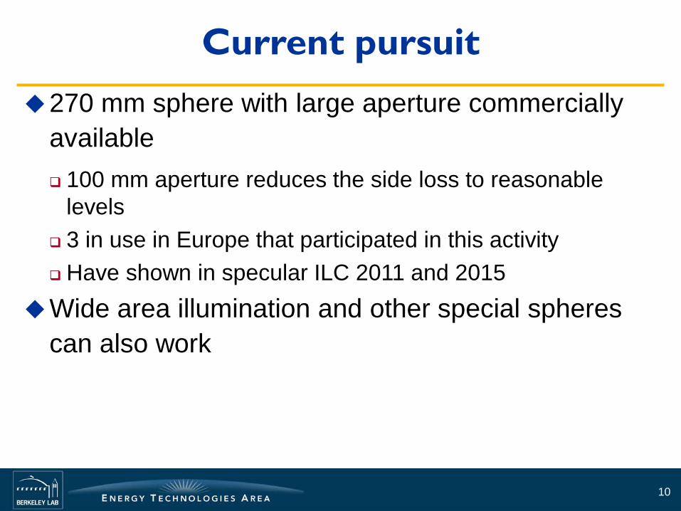
Current pursuit 270 mm sphere with large aperture commercially
available 100 mm aperture reduces the side loss to reasonable
levels 3 in use in Europe that participated in this activity Have shown in specular ILC 2011 and 2015
Wide area illumination and other special spheres can also work
10

The journeys of the L3 laminate sample
NSG at Lathom, UK, Lambda1050 with upward looking 270mm integrating saphere (Perkin Elmer - OMT Solutions)
INSIMa (INstitut Interuniversitaire des Silicates, Sols et Matériaux), Mons, Belgium, Lambda 750 with same sphere
OMT Solutions, Modified 270 mm sphere
All three participants measured with 100 mm and 50 mm apertures
11
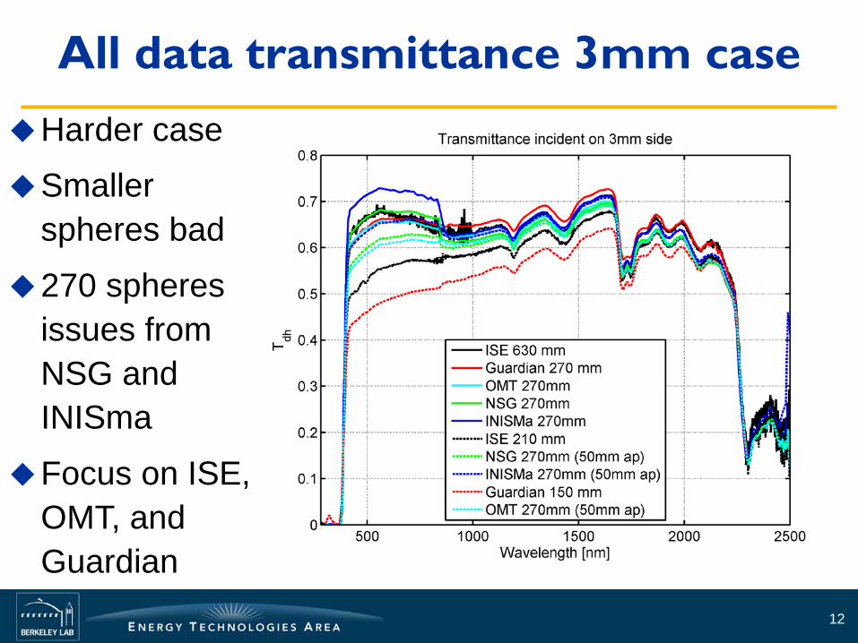
All data transmittance 3mm case
12
Harder case
Smaller spheres bad
270 spheres issues from NSG and INISma
Focus on ISE, OMT, and Guardian

Comparison large spheres
13

270 mm spheres less loss
14
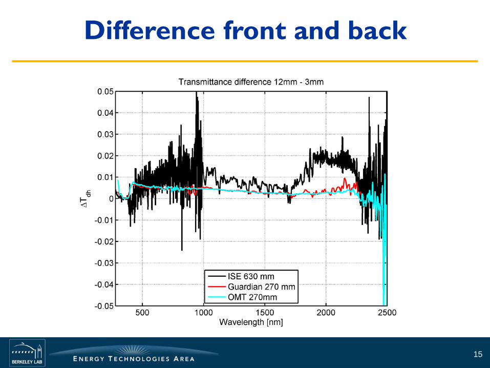
Difference front and back
15

Focus on 270 mm
16
OMT analyzed the issues with high scattering samples and included a modification that significantly reduced
Samples with higher R?

Mimic the design of the Guardian sphere
17
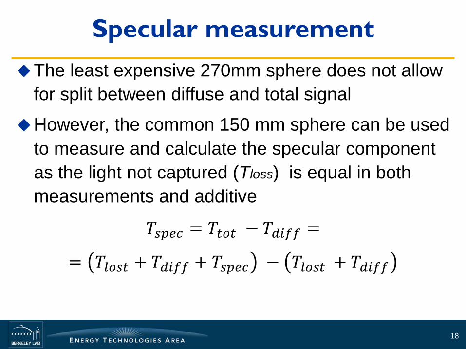
Specular measurement The least expensive 270mm sphere does not allow
for split between diffuse and total signal
However, the common 150 mm sphere can be used to measure and calculate the specular component as the light not captured (Tloss) is equal in both measurements and additive
𝑇𝑠𝑠𝑠𝑠 = 𝑇𝑡𝑡𝑡 − 𝑇𝑑𝑑𝑑𝑑 =
= 𝑇𝑙𝑡𝑠𝑡 + 𝑇𝑑𝑑𝑑𝑑 + 𝑇𝑠𝑠𝑠𝑠 − 𝑇𝑙𝑡𝑠𝑡 + 𝑇𝑑𝑑𝑑𝑑
18

Reflectance The samples
were designed to have a lower reflectance than transmittance
Difference between front 3mm (solid) and 12 mm (dashed)
19
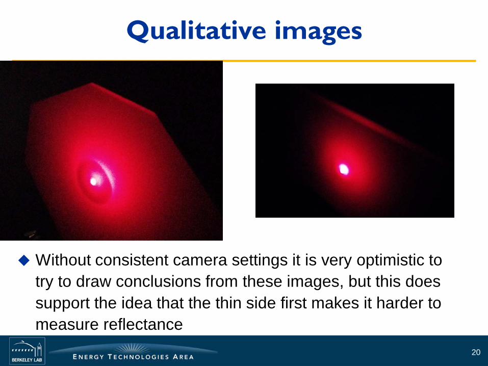
Qualitative images
20
Without consistent camera settings it is very optimistic to try to draw conclusions from these images, but this does support the idea that the thin side first makes it harder to measure reflectance

The scattering particles are in an index matched medium?
21
Riddle from last call why R was lower when the diffusor was closer to the sphere

Goniophotometer measurements Captures angle resolved broadband signal
Side loss has to be on the order of 10 inches
Not trivial to back out parallax but it is small enough to be ignored
22

Angle-resolved data from ISE-pgII
23
Visible value
Almost no difference seen based on position of the diffusing interlayer, i.e. front/back of the sample
0 15 30 45 60 75 900.0
0.2
0.4
0.6
0.8
Tdh,
Rdh
[-]
angle of incidence [°]
Tdh thin toward light, thin-air on axis Tdh thick toward light, thick-air on axis Rdh thin toward light, thin-air on axis Rdh thick toward light, thick-air on axis

Angle-resolved data from lbl-pgII
24
Visible value
Almost no difference seen based on position of the diffusing interlayer
Very low absorption at 10 degrees, solved
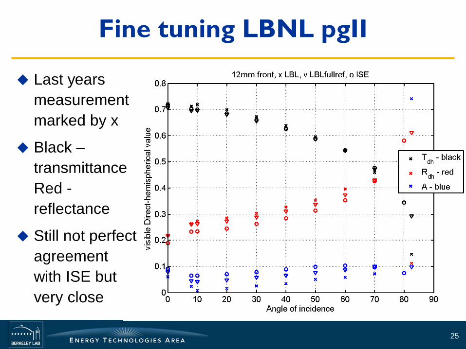
Fine tuning LBNL pgII
25
Last years measurement marked by x
Black – transmittance Red - reflectance
Still not perfect agreement with ISE but very close

Silver edge tape added at LBNL
26

TracePro modeling approach For pursuit of correction factors to use with 150 mm spheres
Accurately modeling interface between the three parts of the sample
Records energy for each surface, i.e. resolves direct-hemispherical transmittance, d-h reflectance, and side-loss for each layer
2-parameter bulk scattering model can be applied to center layer while retaining interface refractive index information of the PVB
27
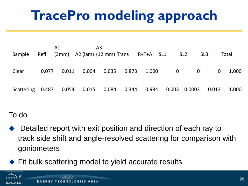
TracePro modeling approach
To do
Detailed report with exit position and direction of each ray to track side shift and angle-resolved scattering for comparison with goniometers
Fit bulk scattering model to yield accurate results
28
Sample Refl A1 (3mm) A2 (lam)
A3 (12 mm) Trans R+T+A SL1 SL2 SL3 Total
Clear 0.077 0.011 0.004 0.035 0.873 1.000 0 0 0 1.000
Scattering 0.487 0.054 0.015 0.084 0.344 0.984 0.003 0.0003 0.013 1.000
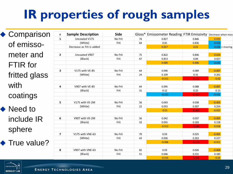
IR properties of rough samples
29
# Sample Description Side Gloss* Emissometer Reading FTIR Emissivity Decrease when movi 1 Uncoated V175 No Frit 74 0.827 0.846 0.019
(White) Frit 64 0.81 0.836 0.026Decrease as frit is added 0.017 0.01 0.036 <-moving d
2 Uncoated V907 No Frit 75 0.822 0.846 0.024(Black) Frit 67 0.813 0.84 0.027
0.009 0.006 0.033
3 V175 with VE-85 No Frit 64 0.096 0.089 -0.007(White) Frit 24 0.109 0.31 0.201
-0.013 -0.221 -0.02
4 V907 with VE-85 No Frit 64 0.095 0.088 -0.007(Black) Frit 31 0.12 0.25 0.13
-0.025 -0.162 -0.032
5 V175 with VE-2M No Frit 56 0.043 0.038 -0.005(White) Frit 22 0.053 0.307 0.254
-0.01 -0.269 -0.015
6 V907 with VE-2M No Frit 56 0.042 0.037 -0.005(Black) Frit 33 0.055 0.183 0.128
-0.013 -0.146 -0.018
7 V175 with VNE-63 No Frit 79 0.03 0.025 -0.005(White) Frit 43 0.036 0.263 0.227
-0.006 -0.238 -0.011
8 V907 with VNE-63 No Frit 82 0.03 0.026 -0.004(Black) Frit 51 0.046 0.231 0.185
-0.016 -0.205 -0.02
Comparison of emisso-meter and FTIR for fritted glass with coatings
Need to include IR sphere
True value?

Ballot strategy No intentional language regarding diffuse glazing in
the current ballot
Decided to try to tidy up documents with editorial changes in separate ballot to not be distracted by these for when the new diffuse language is added
30

Main components to include in 300 partially completed
Definition of how to measure diffuse and specular component
Definition of correction factors for diffuse signals
31
Main components to include in 301 partially completed
Define difference between surface and bulk scattering
Mirror 300 requirements for integrating spheres
Validate emissometer measurements as a viable alternative to IR integrating spheres
Include language for emissometer measurements
32

Main components to include in 302 partially completed
Reporting requirements
Tolerance for light scattering
33

NFRC 300 goals Section 2: Updated the products covered/not
covered for clarity.
Section 3: Updated the year on ASTM E 903, ISO 9050, ISO 15099 and updated the LBNL website.
Section 4 : Updated and added definitions both for clarity of old properties and for new.
Section 6 : Updated wavelength requirements to what is used for the IGDB and filled in gaps in the process
Section 7: Specified specular in one case 34

NFRC 300 short comings We added large thickness as a sample property that
requires special care. A specific number was left out as it would depend on the instrument geometry and the sample properties Planned solution: Change the word definition in 2.2.3 where it
references 6.1. Possibly extend the note in 6.1
We lost a footnote in 2.1 when we moved solar heat gain coefficient, that should stay in
The word Lambertian merits a definition in the terminology
ASTM E275 was updated recently to cut out NIR Update the Referenced documents to contain current titles and year
on the standards
35
NFRC 301 goals and short comings Editorial changes of the blackbody temperature
used, old number “23ºC (75ºF)” replaced by 27ºC
Added standard E408 for FTIR instruments Unintended consequence as it is not recommended for
specular samples Forgot to update year on standards
Added reporting requirements to prepare for other use of integrating spheres and emissometers
36
NFRC 302 goals and short comings
Continue the 302 TG work from 2013
The ASTM standard talking about ILCs has been discontinued Replace reference with outline for the NFRC ILC
procedure
37
Future tasks Update 300 series documents (deal with current
comments) and include work almost finished in
Multi layer calculations need more work but premature if we do not have single layer data
Computational means exist in Berkeley lab WINDOWS and Radiance but require models for angle dependence (incident and outgoing)
Models exist but would require some validation
ILC for measurement of diffuse glazing
38

One pager to research SC Carry out inter-laboratory comparison (ILC) with a
range of samples
Define a data format and implement parsing of that format for inclusion in the CGDB and to use in WINDOW
Generate virtual scattering models using TracePro of the samples used in the ILC. Data used to generate these models will be based on data from the ILC and by using LBNLs pgII goniophotometer.
39