FRG Control Unit
80
vacuum technologies FRG Control Unit INSTRUCTION MANUAL Manual No. tqnb01e1 Revision -- November 2008
Transcript of FRG Control Unit
vacuum technologies
FRG Control Unit
INSTRUCTION MANUAL
Manual No. tqnb01e1 Revision -- November 2008
2
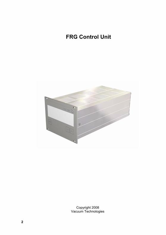
FRG Control Unit
Copyright 2008 Vacuum Technologies
FRG Control Unit
3
Warranty Products manufactured by Seller are warranted against defects in materials and work-manship for twelve (12) months from date of shipment thereof to Customer, and Seller’s liability under valid warranty claims is limited, at the option of Seller, to repair, to replace, or refund of an equitable portion of the purchase price of the Product. Items expendable in normal use are not covered by this warranty. All warranty replacement or repair of parts shall be limited to equipment malfunctions which, in the sole opinion of Seller, are due or traceable to defects in original materials or workmanship. All obligations of Seller under this warranty shall cease in the event of abuse, accident, alteration, misuse, or neglect of the equipment. In-warranty repaired or replaced parts are warranted only for the remaining unexpired portion of the original warranty period applicable to the repaired or replaced parts. After expiration of the applicable warranty period, Customer shall be charged at the then current prices for parts, labor, and transportation. Reasonable care must be used to avoid hazards. Seller expressly disclaims responsibility for loss or damage caused by use of its Products other than in accordance with proper operating procedures. Except as stated herein, Seller makes no warranty, express or implied (either in fact or by operation of law), statutory or otherwise; and, except as stated herein, Seller shall have no liability under any warranty, express or implied (either in fact or by operation of law), statu-tory or otherwise. Statements made by any person, including representatives of Seller, which are inconsistent or in conflict with the terms of this warranty shall not be binding upon Seller unless reduced to writing and approved by an officer of Seller.
Warranty Replacement and Adjustment All claims under warranty must be made promptly after occurrence of circumstances giving rise thereto, and must be received within the applicable warranty period by Seller or its authorized representative. Such claims should include the Product serial number, the date of shipment, and a full description of the circumstances giving rise to the claim. Before any Products are returned for repair and/or adjustment, written authorization from Seller or its authorized representative for the return and instructions as to how and where these Pro-ducts should be returned must be obtained. Any Product returned to Seller for examination shall be prepaid via the means of transportation indicated as acceptable by Seller. Seller reserves the right to reject any warranty claim not promptly reported and any warranty claim on any item that has been altered or has been returned by non-acceptable means of transportation. When any Product is returned for examination and inspection, or for any other reason, Customer shall be responsible for all damage resulting from improper packing or handling, and for loss in transit, not withstanding any defect or non-conformity in the Product. In all cases, Seller has the sole responsibility for determining the cause and nature of failure, and Seller’s determination with regard thereto shall be final. If it is found that Seller’s Product has been returned without cause and is still serviceable, Customer will be notified and the Product returned at Customer’s expense; in addition, a charge for testing and examination may be made on Products so returned. 3/1/00
FRG Control Unit
4
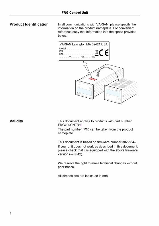
In all communications with VARIAN, please specify the information on the product nameplate. For convenient reference copy that information into the space provided below:
Model:PN: SN: V Hz VA
VARIAN Lexington MA 02421 USA
This document applies to products with part number FRG700CNTR1. The part number (PN) can be taken from the product nameplate. This document is based on firmware number 302-564--. If your unit does not work as described in this document, please check that it is equipped with the above firmware version (→ 42). We reserve the right to make technical changes without prior notice. All dimensions are indicated in mm.
Product Identification
Validity
FRG Control Unit
5
The FRG Control Unit is used together with VARIAN gauges for total pressure measurement. All products must be operated in accordance with their respective Operating Manuals.
1× Single-Channel Controller 1× Power cord 1× Rubber bar 2× Rubber feet 4× Collar screws 4× Plastic sleeves
Intended Use
Scope of Delivery
FRG Control Unit
6
Contents
Warranty 3 Warranty Replacement and Adjustment 3 Product Identification 4 Validity 4 Intended Use 5 Scope of Delivery 5 1 Safety 8 1.1 Symbols Used 8 1.2 Personnel Qualifications 8 1.3 General Safety Instructions 9 2 Technical Data 10 3 Installation 14 3.1 Personnel 14 3.2 Installation, Setup 14 3.2.1 Rack Installation 14 3.2.2 Installation in a Control Panel 19 3.2.3 Use as Desk-Top Unit 20 3.3 Mains Power Connector 21 3.4 SENSOR Connector 23 3.5 CONTROL Connector 24 3.6 RS232 Interface Connector 26 4 Operation 27 4.1 Front Panel 27 4.2 Turning the FRG Control Unit On and Off 28 4.3 Operating Modes 29 4.4 Measurement Mode 30 4.5 Parameter Mode 32 4.5.1 Parameters 34 4.6 Test Mode 40 4.6.1 Parameters 42 4.6.2 Test Programs 43 5 Communication (Serial Interface) 48 5.1 RS232C Interface 48 5.1.1 Data Transmission 48 5.1.2 Communication Protocol 50 5.2 Mnemonics Mnemonics 52 5.2.1 Measurement Mode 53 5.2.2 Parameter Mode 56 5.2.3 Test Mode 59 5.2.4 Example 64 6 Maintenance 65 7 Troubleshooting 66
FRG Control Unit
7
8 Repair 68 9 Accessories 68 10 Storage 68 11 Disposal 69 Appendix 70 A: Conversion Tables 70 B: Default Parameters 71 C: Firmware Update 72 D: Literature 74 E: Index 75 EC Declaration of Conformity 77 For cross-references within this document, the symbol (→ XY) is used, for cross-references to further docu-ments listed under "Literature", the symbol (→ [Z]).
FRG Control Unit
8
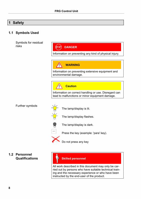
1 Safety
DANGER
Information on preventing any kind of physical injury.
WARNING
Information on preventing extensive equipment and environmental damage.
Caution
Information on correct handling or use. Disregard can lead to malfunctions or minor equipment damage.
The lamp/display is lit.
The lamp/display flashes.
The lamp/display is dark.
Press the key (example: 'para' key).
Do not press any key
Skilled personnel
All work described in this document may only be car-ried out by persons who have suitable technical train-ing and the necessary experience or who have been instructed by the end-user of the product.
1.1 Symbols Used
Symbols for residual risks
Further symbols
1.2 Personnel Qualifications
FRG Control Unit
9
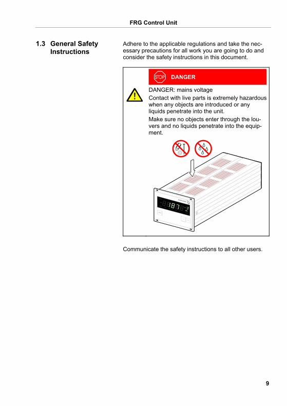
Adhere to the applicable regulations and take the nec-essary precautions for all work you are going to do and consider the safety instructions in this document.
DANGER
DANGER: mains voltage Contact with live parts is extremely hazardous when any objects are introduced or any liquids penetrate into the unit. Make sure no objects enter through the lou-vers and no liquids penetrate into the equip-ment.
Communicate the safety instructions to all other users.
1.3 General Safety Instructions
FRG Control Unit
10
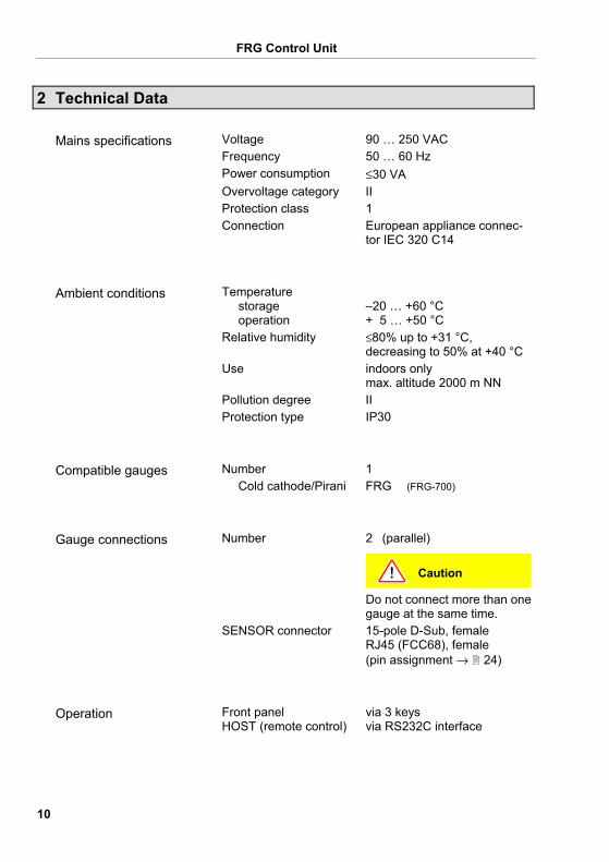
2 Technical Data
Voltage 90 … 250 VAC Frequency 50 … 60 Hz Power consumption ≤30 VA Overvoltage category II Protection class 1 Connection European appliance connec-
tor IEC 320 C14
Temperature storage operation
–20 … +60 °C + 5 … +50 °C
Relative humidity ≤80% up to +31 °C, decreasing to 50% at +40 °C
Use indoors only max. altitude 2000 m NN
Pollution degree II Protection type IP30
Number 1 Cold cathode/Pirani FRG (FRG-700)
Number 2 (parallel)
Caution
Do not connect more than one gauge at the same time.
SENSOR connector 15-pole D-Sub, female RJ45 (FCC68), female (pin assignment → 24)
Front panel HOST (remote control)
via 3 keys via RS232C interface
Mains specifications
Ambient conditions
Compatible gauges
Gauge connections
Operation
FRG Control Unit
11
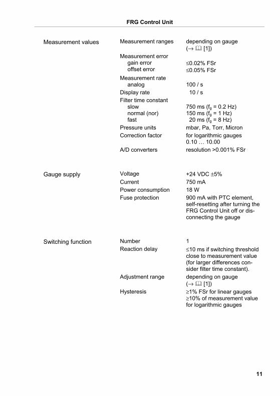
Measurement ranges depending on gauge (→ [1])
Measurement error gain error offset error
≤0.02% FSr ≤0.05% FSr
Measurement rate analog
100 / s
Display rate 10 / s Filter time constant
slow normal (nor) fast
750 ms (fg = 0.2 Hz) 150 ms (fg = 1 Hz) 20 ms (fg = 8 Hz)
Pressure units mbar, Pa, Torr, Micron Correction factor for logarithmic gauges
0.10 … 10.00 A/D converters resolution >0.001% FSr
Voltage +24 VDC ±5% Current 750 mA Power consumption 18 W Fuse protection 900 mA with PTC element,
self-resetting after turning the FRG Control Unit off or dis-connecting the gauge
Number 1 Reaction delay ≤10 ms if switching threshold
close to measurement value (for larger differences con-sider filter time constant).
Adjustment range depending on gauge (→ [1])
Hysteresis ≥1% FSr for linear gauges ≥10% of measurement value for logarithmic gauges
Measurement values
Gauge supply
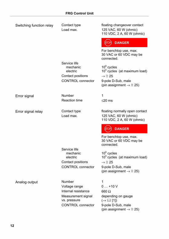
Switching function
FRG Control Unit
12
Contact type floating changeover contact Load max. 125 VAC, 60 W (ohmic)
110 VDC, 2 A, 60 W (ohmic)
DANGER
For benchtop use, max. 30 VAC or 60 VDC may be connected.
Service life mechanic electric
108 cycles 105 cycles (at maximum load)
Contact positions → 25 CONTROL connector 9-pole D-Sub, male
(pin assignment → 25)
Number 1 Reaction time ≤20 ms
Contact type floating normally open contact Load max. 125 VAC, 60 W (ohmic)
110 VDC, 2 A, 60 W (ohmic)
DANGER
For benchtop use, max. 30 VAC or 60 VDC may be connected.
Service life mechanic electric
108 cycles 105 cycles (at maximum load)
Contact positions → 25 CONTROL connector 9-pole D-Sub, male
(pin assignment → 25)
Number 1 Voltage range 0 … +10 V Internal resistance 660 Ω Measurement signal vs. pressure
depending on gauge (→ [1])
CONTROL connector 9-pole D-Sub, male (pin assignment → 25)
Switching function relay
Error signal
Error signal relay
Analog output
FRG Control Unit
13
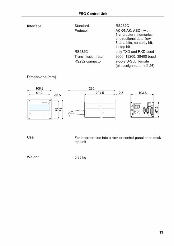
Standard RS232C Protocol ACK/NAK, ASCII with
3-character mnemonics, bi-directional data flow, 8 data bits, no parity bit, 1 stop bit
RS232C only TXD and RXD used Transmission rate 9600, 19200, 38400 baud RS232 connector 9-pole D-Sub, female
(pin assignment → 26)
204.5 2.5285
91.2ø3.5
106.2
78 84 67.3
103.6
For incorporation into a rack or control panel or as desk-top unit
0.85 kg
Interface
Dimensions [mm]
Use
Weight
FRG Control Unit
14
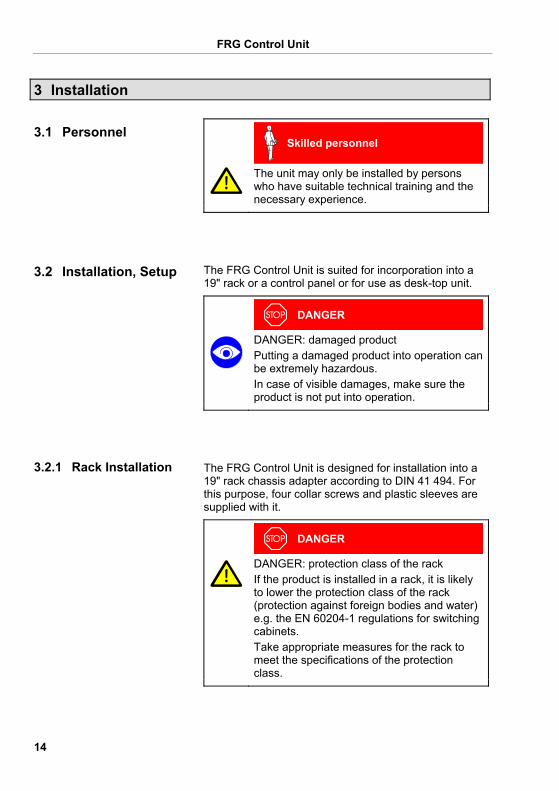
3 Installation
Skilled personnel
The unit may only be installed by persons who have suitable technical training and the necessary experience.
The FRG Control Unit is suited for incorporation into a 19" rack or a control panel or for use as desk-top unit.
DANGER
DANGER: damaged product Putting a damaged product into operation can be extremely hazardous. In case of visible damages, make sure the product is not put into operation.
The FRG Control Unit is designed for installation into a 19" rack chassis adapter according to DIN 41 494. For this purpose, four collar screws and plastic sleeves are supplied with it.
DANGER
DANGER: protection class of the rack If the product is installed in a rack, it is likely to lower the protection class of the rack (protection against foreign bodies and water) e.g. the EN 60204-1 regulations for switching cabinets. Take appropriate measures for the rack to meet the specifications of the protection class.
3.1 Personnel
3.2 Installation, Setup
3.2.1 Rack Installation
FRG Control Unit
15
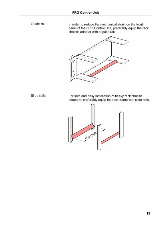
In order to reduce the mechanical strain on the front panel of the FRG Control Unit, preferably equip the rack chassis adapter with a guide rail.
For safe and easy installation of heavy rack chassis adapters, preferably equip the rack frame with slide rails.
Guide rail
Slide rails
FRG Control Unit
16
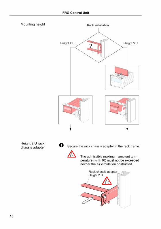
Rack installation
Height 2 U Height 3 U
Secure the rack chassis adapter in the rack frame.
The admissible maximum ambient tem-perature (→ 10) must not be exceeded neither the air circulation obstructed.
Rack chassis adapterHeight 2 U
Mounting height
Height 2 U rack chassis adapter
FRG Control Unit
17
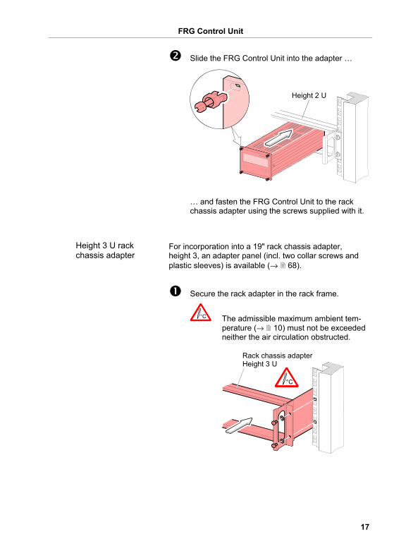
Slide the FRG Control Unit into the adapter …
Height 2 U
… and fasten the FRG Control Unit to the rack chassis adapter using the screws supplied with it.
For incorporation into a 19" rack chassis adapter, height 3, an adapter panel (incl. two collar screws and plastic sleeves) is available (→ 68).
Secure the rack adapter in the rack frame.
The admissible maximum ambient tem-perature (→ 10) must not be exceeded neither the air circulation obstructed.
Rack chassis adapterHeight 3 U
Height 3 U rack chassis adapter
FRG Control Unit
18
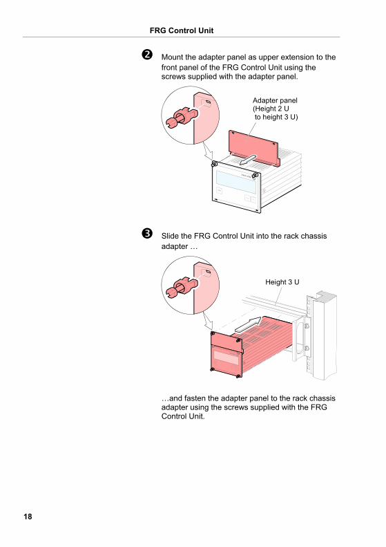
Mount the adapter panel as upper extension to the front panel of the FRG Control Unit using the screws supplied with the adapter panel.
Adapter panel(Height 2 U to height 3 U)
Slide the FRG Control Unit into the rack chassis adapter …
Height 3 U
…and fasten the adapter panel to the rack chassis adapter using the screws supplied with the FRG Control Unit.
FRG Control Unit
19
DANGER
DANGER: protection class of the control panel If the product is installed in a rack, it is likely to lower the protection class of the rack (protection against foreign bodies and water) e.g. according to the EN 60204-1 regulations for switching cabinets. Take appropriate measures for the control panel to meet the specifications of the pro-tection class.
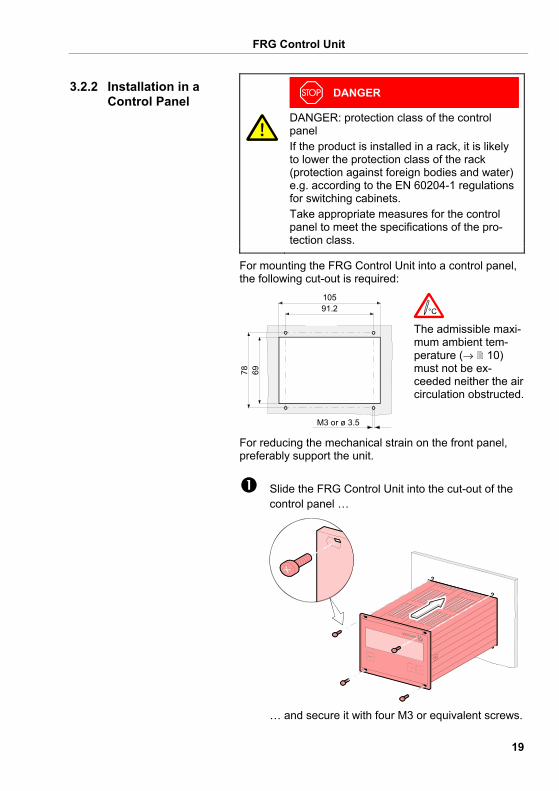
For mounting the FRG Control Unit into a control panel, the following cut-out is required:
10591.2
78 69
M3 or ø 3.5
The admissible maxi-mum ambient tem-perature (→ 10) must not be ex-ceeded neither the air circulation obstructed.
For reducing the mechanical strain on the front panel, preferably support the unit.
Slide the FRG Control Unit into the cut-out of the control panel …
… and secure it with four M3 or equivalent screws.
3.2.2 Installation in a Control Panel
FRG Control Unit
20
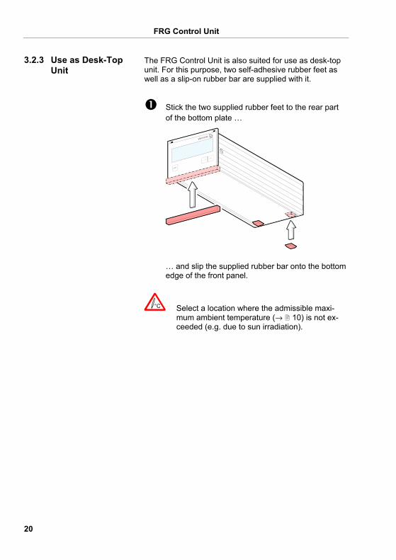
The FRG Control Unit is also suited for use as desk-top unit. For this purpose, two self-adhesive rubber feet as well as a slip-on rubber bar are supplied with it.
Stick the two supplied rubber feet to the rear part of the bottom plate …
… and slip the supplied rubber bar onto the bottom edge of the front panel.
Select a location where the admissible maxi-mum ambient temperature (→ 10) is not ex-ceeded (e.g. due to sun irradiation).
3.2.3 Use as Desk-Top Unit
FRG Control Unit
21
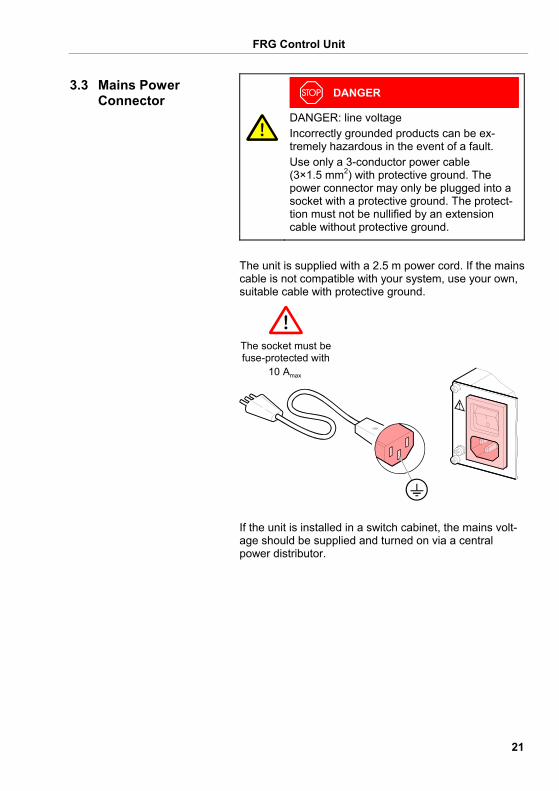
DANGER
DANGER: line voltage Incorrectly grounded products can be ex-tremely hazardous in the event of a fault. Use only a 3-conductor power cable (3×1.5 mm2) with protective ground. The power connector may only be plugged into a socket with a protective ground. The protect-tion must not be nullified by an extension cable without protective ground.
The unit is supplied with a 2.5 m power cord. If the mains cable is not compatible with your system, use your own, suitable cable with protective ground.
10 Amax
The socket must befuse-protected with
If the unit is installed in a switch cabinet, the mains volt-age should be supplied and turned on via a central power distributor.
3.3 Mains Power Connector
FRG Control Unit
22
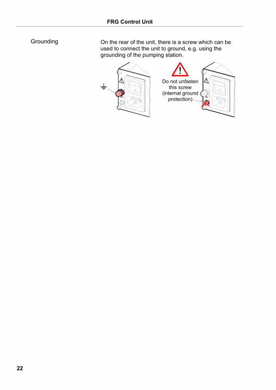
On the rear of the unit, there is a screw which can be used to connect the unit to ground, e.g. using the grounding of the pumping station.
Do not unfastenthis screw
(internal groundprotection)
Grounding
FRG Control Unit
23
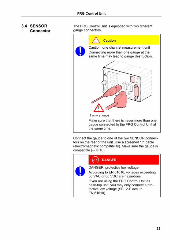
The FRG Control Unit is equipped with two different gauge connectors.
Caution
Caution: one channel measurement unit Connecting more than one gauge at the same time may lead to gauge destruction.
1 only at once Make sure that there is never more than one gauge connected to the FRG Control Unit at the same time.
Connect the gauge to one of the two SENSOR connec-tors on the rear of the unit. Use a screened 1:1 cable (electromagnetic compatibility). Make sure the gauge is compatible (→ 10).
DANGER
DANGER: protective low voltage According to EN 61010, voltages exceeding 30 VAC or 60 VDC are hazardous. If you are using the FRG Control Unit as desk-top unit, you may only connect a pro-tective low voltage (SELV-E acc. to EN 61010).
3.4 SENSOR Connector
FRG Control Unit
24
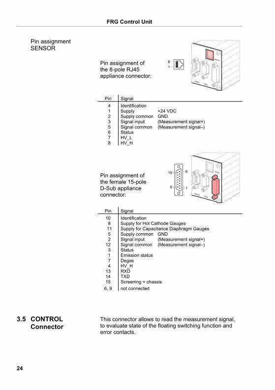
Pin assignment of the 8-pole RJ45 appliance connector:
81
Pin Signal 4 1 2 3 5 6 7 8
Identification Supply +24 VDC Supply common GND Signal input (Measurement signal+) Signal common (Measurement signal–) Status HV_L HV_H
Pin assignment of the female 15-pole D-Sub appliance connector:
15 8
9 1
Pin Signal 10 8 11 5 2 12 3 1 7 4 13 14 15
6, 9
Identification Supply for Hot Cathode Gauges Supply for Capacitance Diaphragm Gauges Supply common GND Signal input (Measurement signal+) Signal common (Measurement signal–) Status Emission status Degas HV_H RXD TXD Screening = chassis not connected
This connector allows to read the measurement signal, to evaluate state of the floating switching function and error contacts.
Pin assignment SENSOR
3.5 CONTROL Connector
FRG Control Unit
25
Connect the peripheral components to the CONTROL connector on the rear of the unit. Use a shielded cable (electromagnetic com-patibility).
DANGER
DANGER: protective low voltage According to EN 61010, voltages ex-ceeding 30 VAC or 60 VDC are haz-ardous. If you are using the FRG Control Unit as desk-top unit, you may only con-nect a protective low voltage (SELV-E acc. to EN 61010).
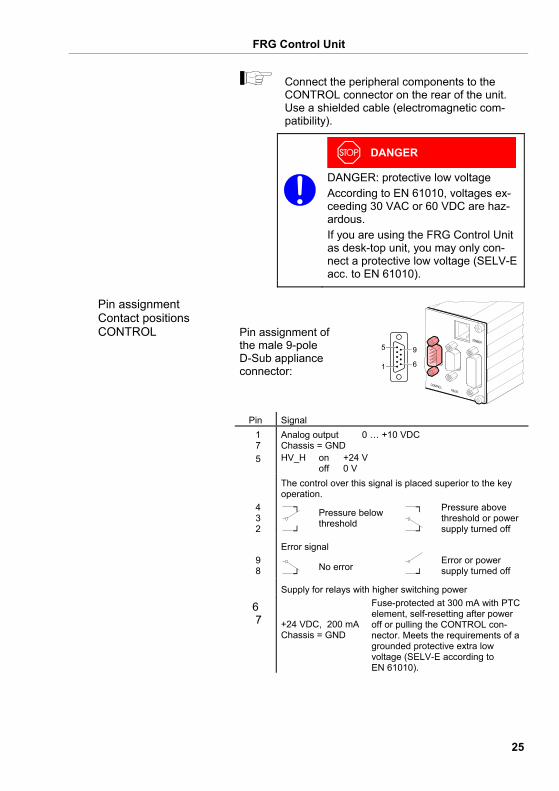
Pin assignment of the male 9-pole D-Sub appliance connector:
5
1
9
6
Pin Signal 1 7 5
Analog output 0 … +10 VDC Chassis = GND HV_H on +24 V off 0 V
The control over this signal is placed superior to the key operation.
4 3 2
Pressure below threshold
Pressure above threshold or power supply turned off
Error signal 9 8 No error
Error or power supply turned off
Supply for relays with higher switching power
6 7 +24 VDC, 200 mA
Chassis = GND
Fuse-protected at 300 mA with PTC element, self-resetting after power off or pulling the CONTROL con-nector. Meets the requirements of a grounded protective extra low voltage (SELV-E according to EN 61010).
Pin assignment Contact positions CONTROL
FRG Control Unit
26
The RS232C interface allows for operating the FRG Control Unit via a HOST or terminal. It can also be used for updating the firmware (→ 72).
Connect the serial interface to the RS232 con-nector on the rear of the unit using your own, screened (electromagnetic compatibility) cable.
DANGER
DANGER: protective low voltage According to EN 61010, voltages ex-ceeding 30 VAC or 60 VDC are haz-ardous. If you are using the FRG Control Unit as desk-top unit, you may only con-nect a protective low voltage (SELV-E acc. to EN 61010).
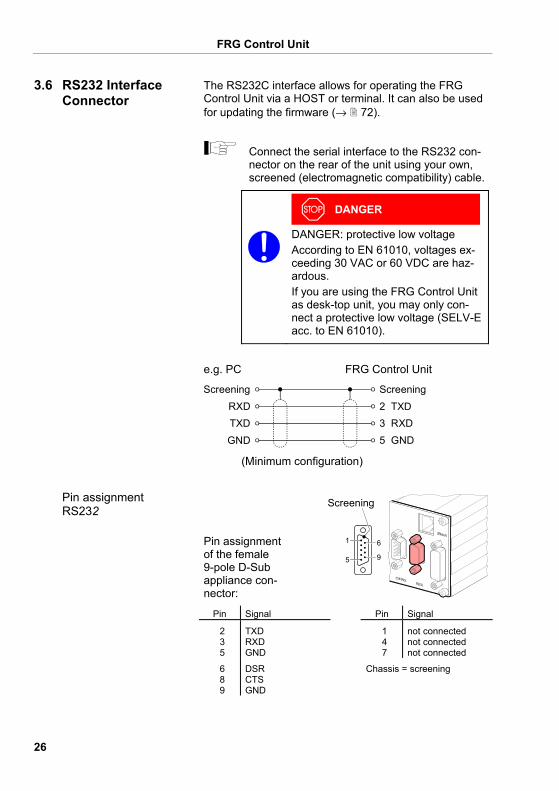
e.g. PC FRG Control Unit
2 TXDRXD3 RXDTXD5 GNDGND
Screening Screening
(Minimum configuration)
Pin assignment of the female 9-pole D-Sub appliance con-nector:
1
5
6
9
Screening
Pin Signal Pin Signal
2 3 5
TXD RXD GND
1 4 7
not connected not connected not connected
6 8 9
DSR CTS GND
Chassis = screening
3.6 RS232 Interface Connector
Pin assignment RS232
FRG Control Unit
27
4 Operation
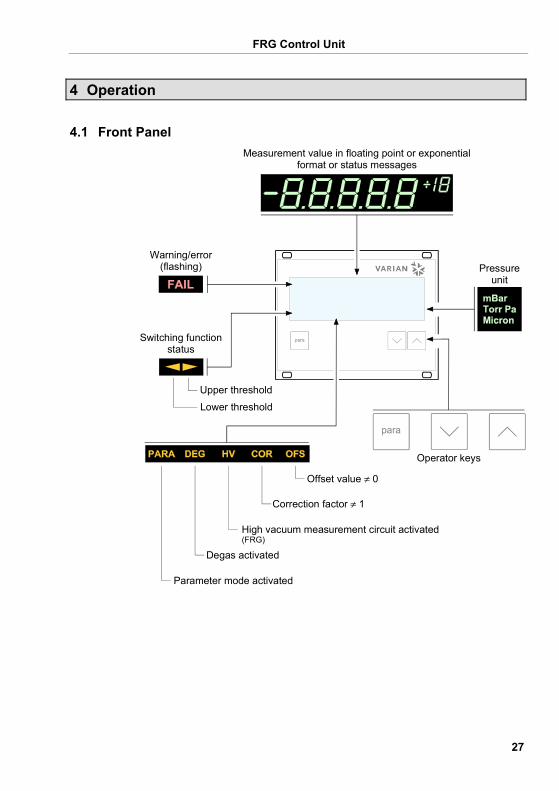
Operator keys
Pressureunit
Switching functionstatus
Upper threshold
Lower threshold
Degas activated
Offset value ≠ 0
Correction factor ≠ 1
High vacuum measurement circuit activated(FRG)
Parameter mode activated
Measurement value in floating point or exponentialformat or status messages
Warning/error(flashing)
4.1 Front Panel
FRG Control Unit
28
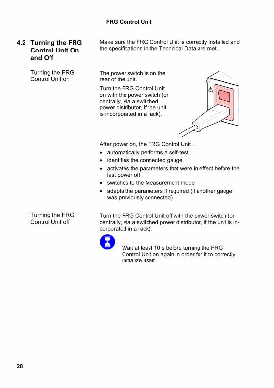
Make sure the FRG Control Unit is correctly installed and the specifications in the Technical Data are met.
The power switch is on the rear of the unit. Turn the FRG Control Unit on with the power switch (or centrally, via a switched power distributor, if the unit is incorporated in a rack).
After power on, the FRG Control Unit … • automatically performs a self-test • identifies the connected gauge • activates the parameters that were in effect before the
last power off • switches to the Measurement mode • adapts the parameters if required (if another gauge
was previously connected).
Turn the FRG Control Unit off with the power switch (or centrally, via a switched power distributor, if the unit is in-corporated in a rack).
Wait at least 10 s before turning the FRG Control Unit on again in order for it to correctly initialize itself.
4.2 Turning the FRG Control Unit On and Off
Turning the FRG Control Unit on
Turning the FRG Control Unit off
FRG Control Unit
29
The FRG Control Unit works in the following operating modes: • Measurement mode
for displaying measurement values or status mes-sages (→ 30)
• Parameter mode for entering or displaying parameters (→ 32)
• Test mode for running internal test programs (→ 40)
• Program transfer mode for updating the firmware (→ 72)
4.3 Operating Modes
FRG Control Unit
30
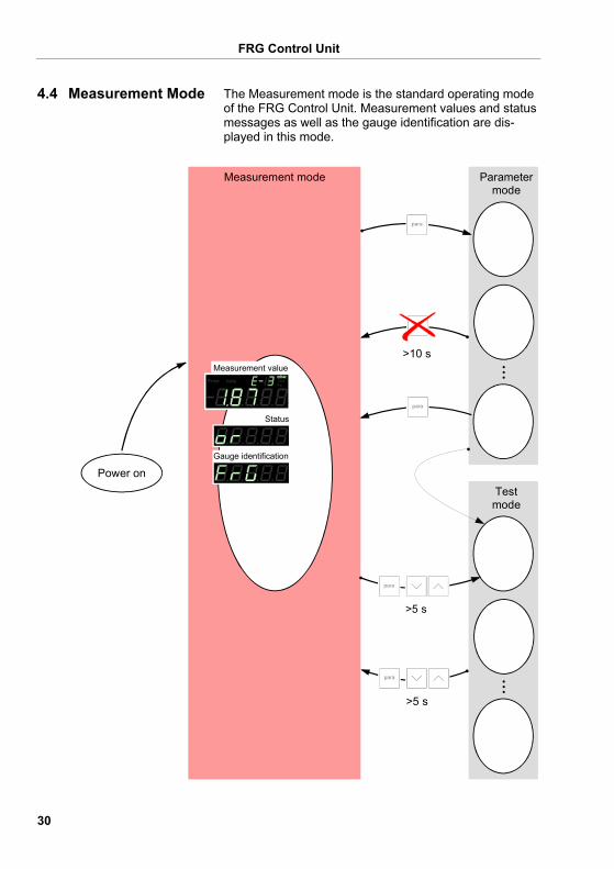
The Measurement mode is the standard operating mode of the FRG Control Unit. Measurement values and status messages as well as the gauge identification are dis-played in this mode.
Testmode
Parametermode
>5 s
Status
Measurement value
Gauge identification
Measurement mode
>5 s
>10 s
Power on
4.4 Measurement Mode
FRG Control Unit
31
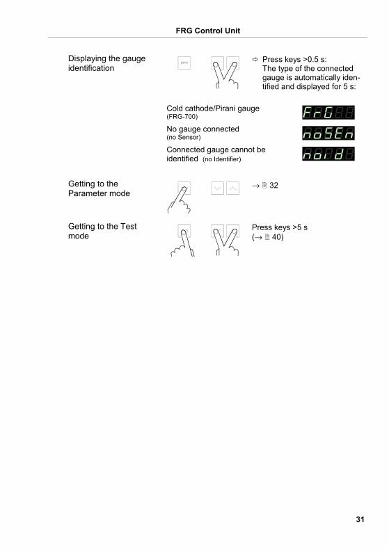
Press keys >0.5 s: The type of the connected gauge is automatically iden-tified and displayed for 5 s:
Cold cathode/Pirani gauge (FRG-700) No gauge connected (no Sensor) Connected gauge cannot be identified (no Identifier)
→ 32
Press keys >5 s (→ 40)
Displaying the gauge identification
Getting to the Parameter mode
Getting to the Test mode
FRG Control Unit
32
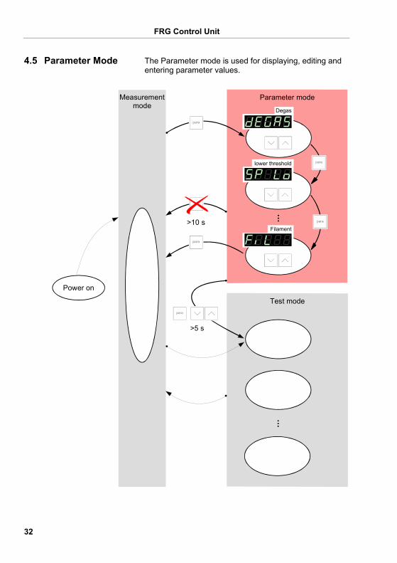
The Parameter mode is used for displaying, editing and entering parameter values.
Filament
Parameter mode
lower threshold
Degas
Test mode
Measurementmode
Power on
>5 s
>10 s
4.5 Parameter Mode
FRG Control Unit
33
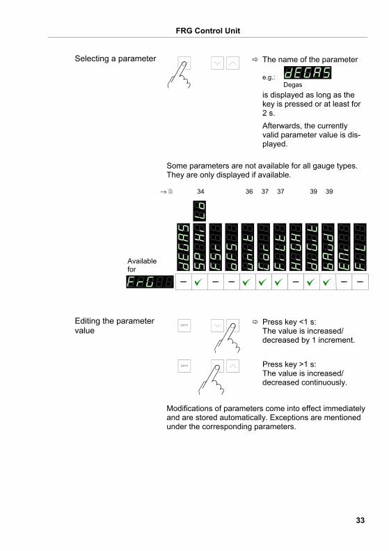
The name of the parameter
e.g.: Degas
is displayed as long as the key is pressed or at least for 2 s.
Afterwards, the currently valid parameter value is dis-played.
Some parameters are not available for all gauge types. They are only displayed if available.
→ 34 36 37 37 39 39
Available for
Press key <1 s: The value is increased/ decreased by 1 increment.
Press key >1 s: The value is increased/ decreased continuously.
Modifications of parameters come into effect immediately and are stored automatically. Exceptions are mentioned under the corresponding parameters.
Selecting a parameter
Editing the parameter value
FRG Control Unit
34
Press keys >5 s: All user-defined parameters are restored to their default values (→ 71).
Loading of the default parameter settings is irreversible.
Press keys >5 s (→ 40)
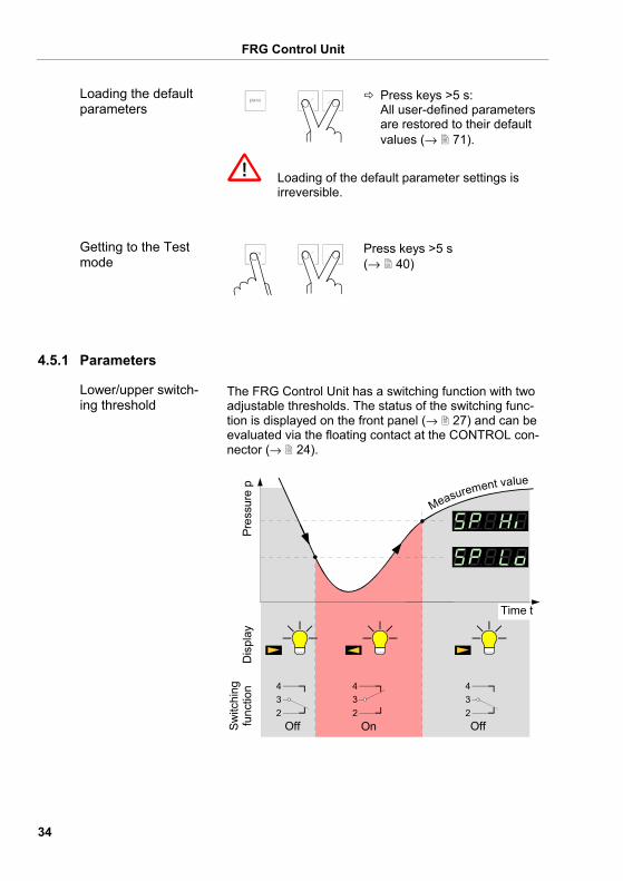
The FRG Control Unit has a switching function with two adjustable thresholds. The status of the switching func-tion is displayed on the front panel (→ 27) and can be evaluated via the floating contact at the CONTROL con-nector (→ 24).
234
234
234
Measurement value
Pres
sure
pD
ispl
aySw
itchi
ngfu
nctio
n
Time t
Off On Off
Loading the default parameters
Getting to the Test mode
4.5.1 Parameters
Lower/upper switch-ing threshold
FRG Control Unit
35
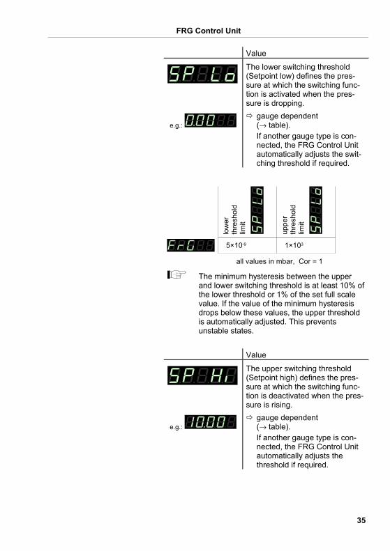
Value
The lower switching threshold (Setpoint low) defines the pres-sure at which the switching func-tion is activated when the pres-sure is dropping.
e.g.: gauge dependent (→ table). If another gauge type is con-nected, the FRG Control Unit automatically adjusts the swit-ching threshold if required.
low
erth
resh
old
limit
uppe
rth
resh
old
limit
all values in mbar, Cor = 1
5×10⁻⁹ 1×10³
The minimum hysteresis between the upper and lower switching threshold is at least 10% of the lower threshold or 1% of the set full scale value. If the value of the minimum hysteresis drops below these values, the upper threshold is automatically adjusted. This prevents unstable states.
Value
The upper switching threshold (Setpoint high) defines the pres-sure at which the switching func-tion is deactivated when the pres-sure is rising.
e.g.: gauge dependent (→ table). If another gauge type is con-nected, the FRG Control Unit automatically adjusts the threshold if required.
FRG Control Unit
36
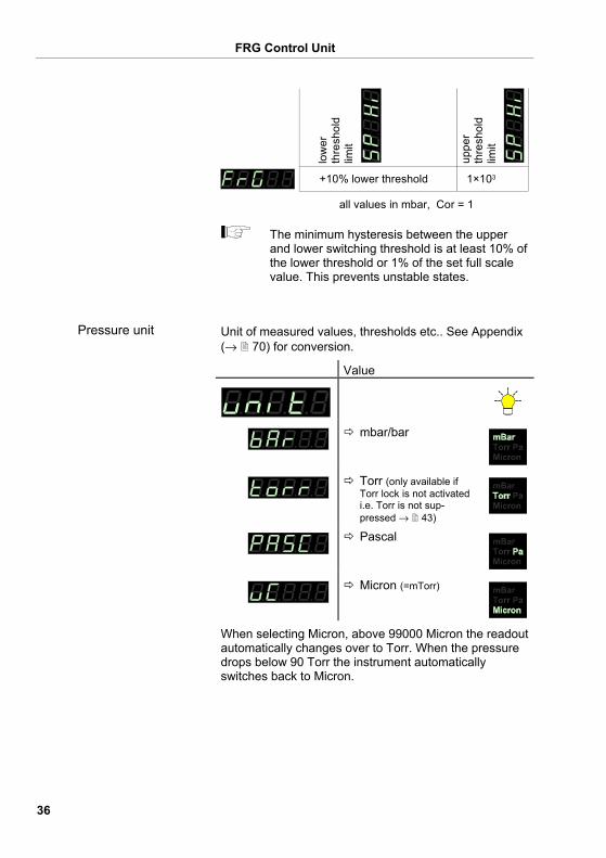
1×10³
low
erth
resh
old
limit
uppe
rth
resh
old
limit
+10% lower threshold
all values in mbar, Cor = 1
The minimum hysteresis between the upper and lower switching threshold is at least 10% of the lower threshold or 1% of the set full scale value. This prevents unstable states.
Unit of measured values, thresholds etc.. See Appendix (→ 70) for conversion.
Value
mbar/bar
Torr (only available if Torr lock is not activated i.e. Torr is not sup-pressed → 43)
Pascal
Micron (=mTorr)
When selecting Micron, above 99000 Micron the readout automatically changes over to Torr. When the pressure drops below 90 Torr the instrument automatically switches back to Micron.
Pressure unit
FRG Control Unit
37
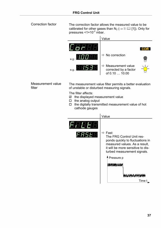
The correction factor allows the measured value to be calibrated for other gases than N2 (→ [1]). Only for pressures <1×10⁻² mbar.
Value
e.g.: No correction
e.g.: Measurement value corrected by a factor of 0.10 … 10.00
The measurement value filter permits a better evaluation of unstable or disturbed measuring signals. The filter affects:
the displayed measurement value the analog output the digitally transmitted measurement value of hot
cathode gauges Value
Fast: The FRG Control Unit res-ponds quickly to fluctuations in measured values. As a result, it will be more sensitive to dis-turbed measurement signals.
Pressure p
Time t
Correction factor
Measurement value filter
FRG Control Unit
38
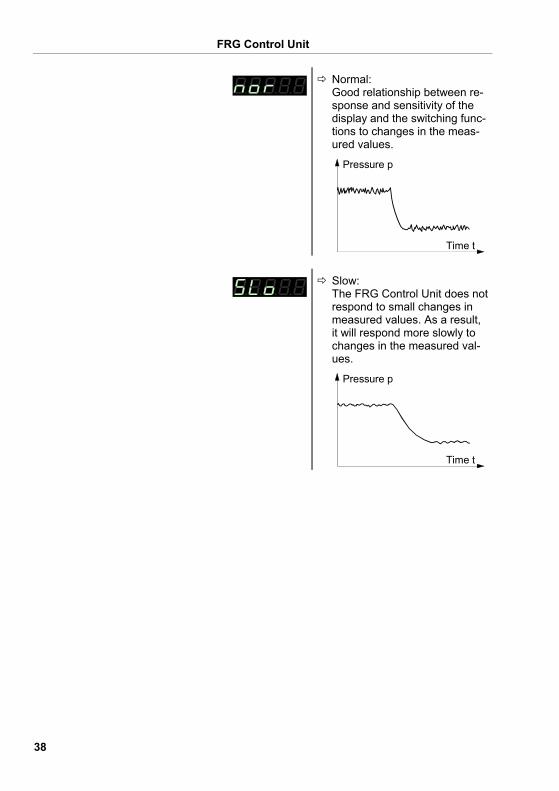
Normal: Good relationship between re-sponse and sensitivity of the display and the switching func-tions to changes in the meas-ured values.
Pressure p
Time t
Slow: The FRG Control Unit does not respond to small changes in measured values. As a result, it will respond more slowly to changes in the measured val-ues.
Pressure p
Time t
FRG Control Unit
39
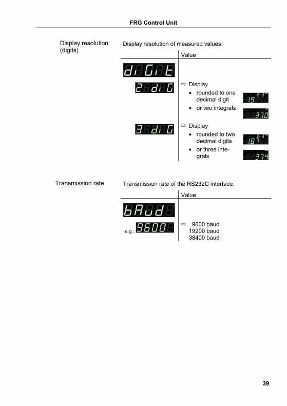
Display resolution of measured values.
Value
Display • rounded to one
decimal digit • or two integrals
Display • rounded to two
decimal digits • or three inte-
grals
Transmission rate of the RS232C interface.
Value
e.g.: 9600 baud 19200 baud 38400 baud
Display resolution (digits)
Transmission rate
FRG Control Unit
40
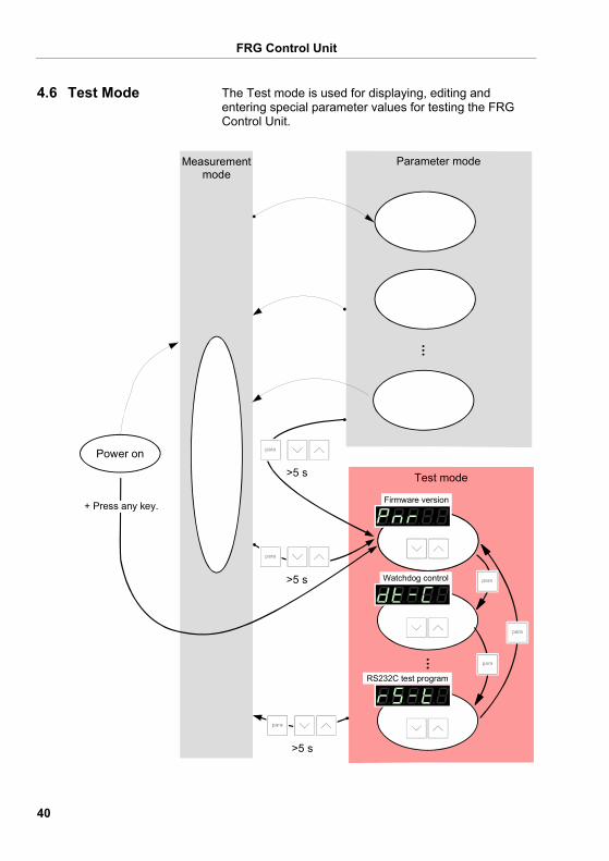
The Test mode is used for displaying, editing and entering special parameter values for testing the FRG Control Unit.
Power on
Parameter mode
Firmware version
Watchdog control
RS232C test program
Test mode
Measurementmode
>5 s
>5 s
>5 s
+ Press any key.
4.6 Test Mode
FRG Control Unit
41
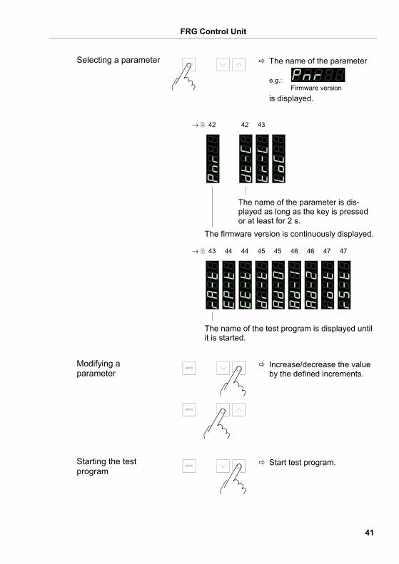
The name of the parameter
e.g.: Firmware version
is displayed.
→ 42 42 43
The name of the parameter is dis-played as long as the key is pressed or at least for 2 s.
The firmware version is continuously displayed.
→ 43 44 44 45 45 46 46 47 47
The name of the test program is displayed until it is started.
Increase/decrease the value by the defined increments.
Start test program.
Selecting a parameter
Modifying a parameter
Starting the test program
FRG Control Unit
42
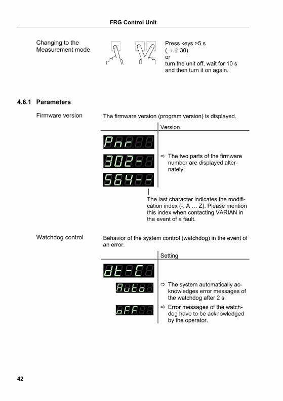
Press keys >5 s (→ 30) or turn the unit off, wait for 10 s and then turn it on again.
The firmware version (program version) is displayed.
Version
The two parts of the firmware number are displayed alter-nately.
│ The last character indicates the modifi-cation index (-, A … Z). Please mention this index when contacting VARIAN in the event of a fault.
Behavior of the system control (watchdog) in the event of an error.
Setting
The system automatically ac-knowledges error messages of the watchdog after 2 s.
Error messages of the watch-dog have to be acknowledged by the operator.
Changing to the Measurement mode
4.6.1 Parameters
Firmware version
Watchdog control
FRG Control Unit
43
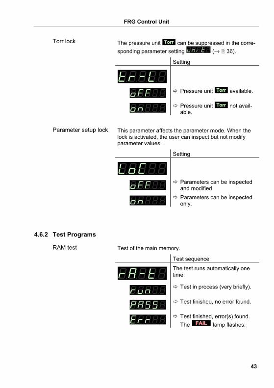
The pressure unit can be suppressed in the corre-sponding parameter setting (→ 36).
Setting
Pressure unit available.
Pressure unit not avail-able.
This parameter affects the parameter mode. When the lock is activated, the user can inspect but not modify parameter values.
Setting
Parameters can be inspected and modified
Parameters can be inspected only.
Test of the main memory.
Test sequence
The test runs automatically one time:
Test in process (very briefly).
Test finished, no error found.
Test finished, error(s) found. The lamp flashes.
Torr lock
Parameter setup lock
4.6.2 Test Programs
RAM test
FRG Control Unit
44
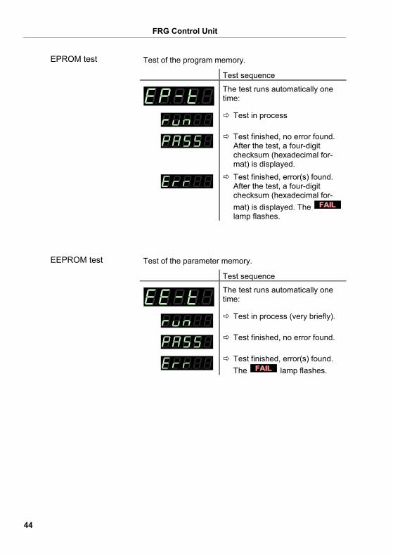
Test of the program memory.
Test sequence
The test runs automatically one time:
Test in process
Test finished, no error found. After the test, a four-digit checksum (hexadecimal for-mat) is displayed.
Test finished, error(s) found. After the test, a four-digit checksum (hexadecimal for-mat) is displayed. The lamp flashes.
Test of the parameter memory.
Test sequence
The test runs automatically one time:
Test in process (very briefly).
Test finished, no error found.
Test finished, error(s) found. The lamp flashes.
EPROM test
EEPROM test
FRG Control Unit
45
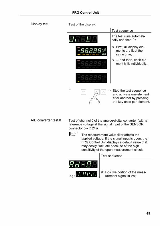
Test of the display.
Test sequence
The test runs automati-cally one time 1):
First, all display ele-ments are lit at the same time, ...
HV COR
:
HV COR
... and then, each ele-ment is lit individually.
1) Stop the test sequence
and activate one element after another by pressing the key once per element.
Test of channel 0 of the analog/digital converter (with a reference voltage at the signal input of the SENSOR connector (→ 24)).
The measurement value filter affects the applied voltage. If the signal input is open, the FRG Control Unit displays a default value that may easily fluctuate because of the high sensitivity of the open measurement circuit.
Test sequence
e.g.: Positive portion of the meas-urement signal in Volt
Display test
A/D converter test 0
FRG Control Unit
46
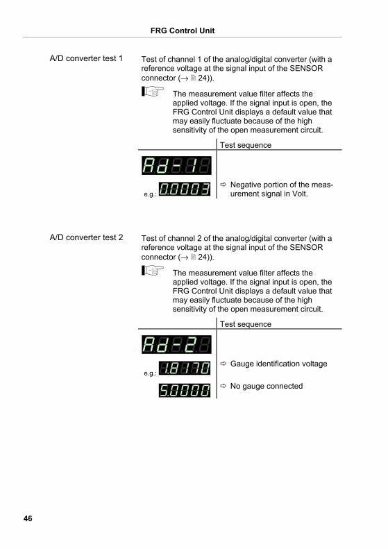
Test of channel 1 of the analog/digital converter (with a reference voltage at the signal input of the SENSOR connector (→ 24)).
The measurement value filter affects the applied voltage. If the signal input is open, the FRG Control Unit displays a default value that may easily fluctuate because of the high sensitivity of the open measurement circuit.
Test sequence
e.g.: Negative portion of the meas-urement signal in Volt.
Test of channel 2 of the analog/digital converter (with a reference voltage at the signal input of the SENSOR connector (→ 24)).
The measurement value filter affects the applied voltage. If the signal input is open, the FRG Control Unit displays a default value that may easily fluctuate because of the high sensitivity of the open measurement circuit.
Test sequence
e.g.: Gauge identification voltage
No gauge connected
A/D converter test 1
A/D converter test 2

FRG Control Unit
47
Test of the two relays of the FRG Control Unit. The pro-gram tests their switching function.
Caution
Caution: The relays switch irrespective of the pressure Starting a test program may cause unwanted effects in connected control systems. Disconnect all sensor cables and control system lines to ensure that no control com-mands or messages are triggered by mistake.
The relays switch on and off cyclically. The switching operations are indicated optically and can be heard. The contacts are connected to the CONTROL connector on the rear of the housing (→ 24). Check the switching function with an ohmmeter.
Test sequence
The test runs automatically one time:
both relays deactivated
switching function relay
switching function relay
error relay
error relay
Test of the RS232C interface. The FRG Control Unit repeats each sign transmitted by the communicating HOST.
The data transferred from/to the FRG Control Unit can be displayed by the computer only (→ Section 5).
Test sequence
The test runs automatically.
I/O test
RS232C test
FRG Control Unit
48
5 Communication (Serial Interface)
The serial interface is used for communication between the FRG Control Unit and a computer. A terminal can be connected for test purposes. When the FRG Control Unit is put into operation, it starts transmitting measured values in intervals of 1 s. As soon as the first character is transferred to the FRG Control Unit, the automatic transmission of measured values stops. After the necessary inquiries or parameter modi-fications have been made, the transmission of measured values can be started again with the COM command (→ 54).
Pin assignment of the 9-pin D-Sub connector and RS232 cable → 26.
The data transmission is bi-directional, i.e. data and control commands can be transmitted in either direction.
1 start bit 8 data bits No parity bit 1 stop bit No hardware handshake
5.1 RS232C Interface
Connection diagram, connection cable
5.1.1 Data Transmission
Data format
FRG Control Unit
49
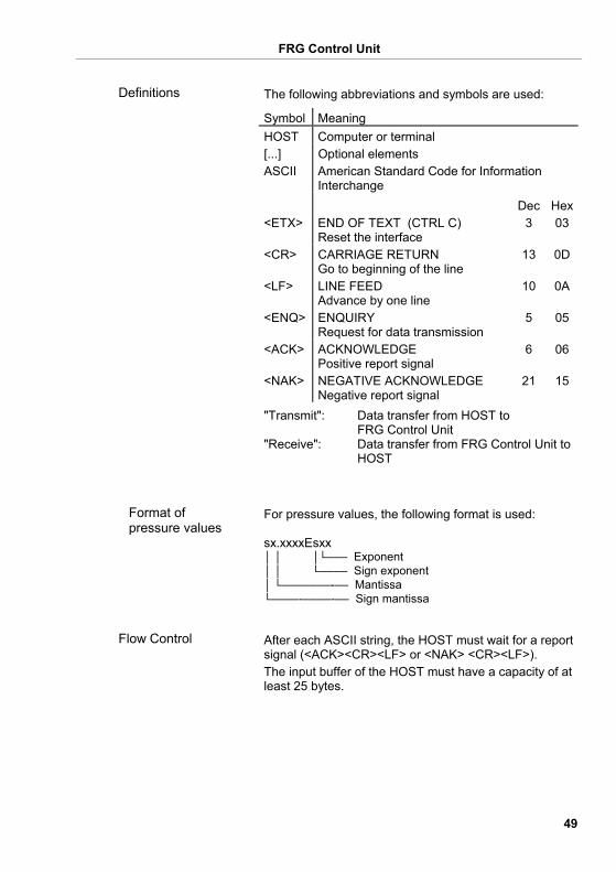
The following abbreviations and symbols are used:
Symbol Meaning HOST Computer or terminal [...] Optional elements ASCII American Standard Code for Information
Interchange Dec Hex <ETX> END OF TEXT (CTRL C)
Reset the interface 3 03
<CR> CARRIAGE RETURN Go to beginning of the line
13 0D
<LF> LINE FEED Advance by one line
10 0A
<ENQ> ENQUIRY Request for data transmission
5 05
<ACK> ACKNOWLEDGE Positive report signal
6 06
<NAK> NEGATIVE ACKNOWLEDGE Negative report signal
21 15
"Transmit": Data transfer from HOST to FRG Control Unit "Receive": Data transfer from FRG Control Unit to HOST
For pressure values, the following format is used: sx.xxxxEsxx │ │ │└─── Exponent │ │ └──── Sign exponent │ └───────-── Mantissa └────-────-── Sign mantissa
After each ASCII string, the HOST must wait for a report signal (<ACK><CR><LF> or <NAK> <CR><LF>). The input buffer of the HOST must have a capacity of at least 25 bytes.
Definitions
Format of pressure values
Flow Control
FRG Control Unit
50
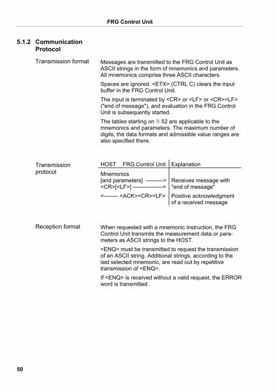
Messages are transmitted to the FRG Control Unit as ASCII strings in the form of mnemonics and parameters. All mnemonics comprise three ASCII characters. Spaces are ignored. <ETX> (CTRL C) clears the input buffer in the FRG Control Unit. The input is terminated by <CR> or <LF> or <CR><LF> ("end of message"), and evaluation in the FRG Control Unit is subsequently started. The tables starting on 52 are applicable to the mnemonics and parameters. The maximum number of digits, the data formats and admissible value ranges are also specified there.
HOST FRG Control Unit Explanation
Mnemonics [and parameters] ––-–––><CR>[<LF>] –––––––-––>
Receives message with "end of message"
<–-––– <ACK><CR><LF> Positive acknowledgment of a received message
When requested with a mnemonic instruction, the FRG Control Unit transmits the measurement data or para-meters as ASCII strings to the HOST. <ENQ> must be transmitted to request the transmission of an ASCII string. Additional strings, according to the last selected mnemonic, are read out by repetitive transmission of <ENQ>. If <ENQ> is received without a valid request, the ERROR word is transmitted.
5.1.2 Communication Protocol
Transmission format
Transmission protocol
Reception format
FRG Control Unit
51
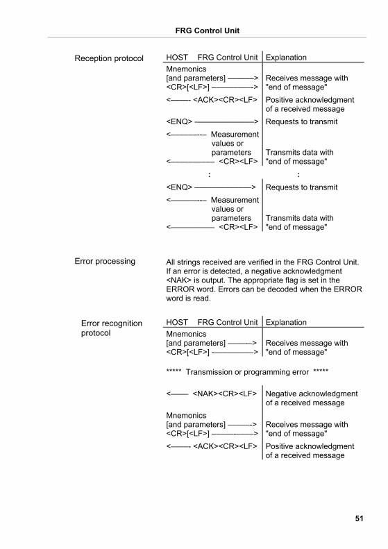
HOST FRG Control Unit Explanation Mnemonics [and parameters] ––––––><CR>[<LF>] –––––––––->
Receives message with "end of message"
<––––- <ACK><CR><LF> Positive acknowledgment of a received message
<ENQ> -–––––––––––––> Requests to transmit <––––––--– Measurement values or parameters <–––––––––– <CR><LF>
Transmits data with "end of message"
: : <ENQ> –––––––––––––> Requests to transmit <––––––--– Measurement values or parameters <–––––––––– <CR><LF>
Transmits data with "end of message"
All strings received are verified in the FRG Control Unit. If an error is detected, a negative acknowledgment <NAK> is output. The appropriate flag is set in the ERROR word. Errors can be decoded when the ERROR word is read.
HOST FRG Control Unit Explanation Mnemonics [and parameters] ––––-–><CR>[<LF>] -–––––––––>
Receives message with "end of message"
***** Transmission or programming error ***** <–––– <NAK><CR><LF> Negative acknowledgment
of a received message Mnemonics [and parameters] –––––-><CR>[<LF>] –––––-––––>
Receives message with "end of message"
<––––- <ACK><CR><LF> Positive acknowledgment of a received message
Reception protocol
Error processing
Error recognition protocol
FRG Control Unit
52
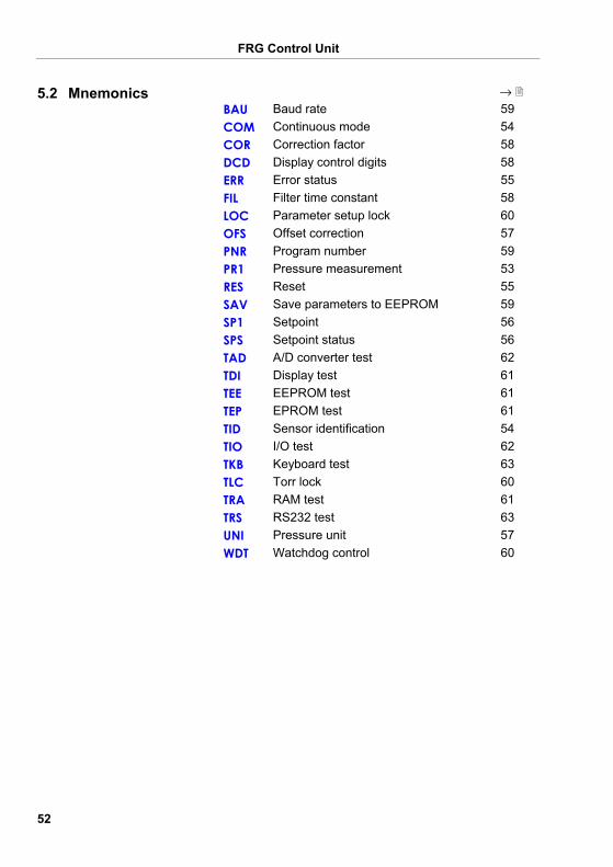
→ BAU Baud rate 59 COM Continuous mode 54 COR Correction factor 58 DCD Display control digits 58 ERR Error status 55 FIL Filter time constant 58 LOC Parameter setup lock 60 OFS Offset correction 57 PNR Program number 59 PR1 Pressure measurement 53 RES Reset 55 SAV Save parameters to EEPROM 59 SP1 Setpoint 56 SPS Setpoint status 56 TAD A/D converter test 62 TDI Display test 61 TEE EEPROM test 61 TEP EPROM test 61 TID Sensor identification 54 TIO I/O test 62 TKB Keyboard test 63 TLC Torr lock 60 TRA RAM test 61 TRS RS232 test 63 UNI Pressure unit 57 WDT Watchdog control 60
5.2 Mnemonics
FRG Control Unit
53
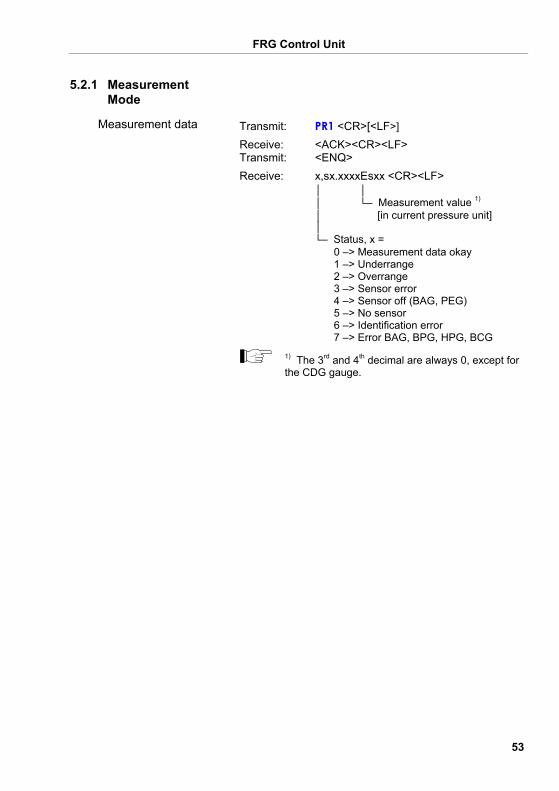
Transmit: PR1 <CR>[<LF>] Receive: <ACK><CR><LF> Transmit: <ENQ> Receive: x,sx.xxxxEsxx <CR><LF>
│ │ │ └─ Measurement value 1) │ [in current pressure unit] │ └─ Status, x = 0 –> Measurement data okay 1 –> Underrange 2 –> Overrange 3 –> Sensor error 4 –> Sensor off (BAG, PEG) 5 –> No sensor 6 –> Identification error 7 –> Error BAG, BPG, HPG, BCG
1) The 3rd and 4th decimal are always 0, except for the CDG gauge.
5.2.1 Measurement Mode
Measurement data
FRG Control Unit
54
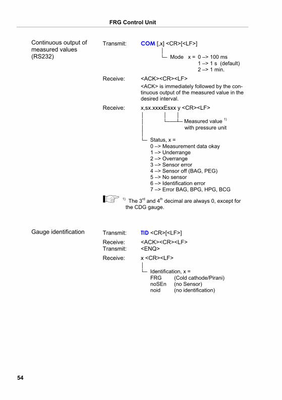
Transmit: COM [,x] <CR>[<LF>] │ └─ Mode x = 0 –> 100 ms 1 –> 1 s (default) 2 –> 1 min.
Receive: <ACK><CR><LF> <ACK> is immediately followed by the con-tinuous output of the measured value in the desired interval.
Receive: x,sx.xxxxEsxx y <CR><LF> │ │ │ │ └───┴─ Measured value 1) │ with pressure unit │ └─ Status, x = 0 –> Measurement data okay 1 –> Underrange 2 –> Overrange 3 –> Sensor error 4 –> Sensor off (BAG, PEG) 5 –> No sensor 6 –> Identification error 7 –> Error BAG, BPG, HPG, BCG
1) The 3rd and 4th decimal are always 0, except for the CDG gauge.
Transmit: TID <CR>[<LF>] Receive: <ACK><CR><LF> Transmit: <ENQ> Receive: x <CR><LF>
│ └─ Identification, x = FRG (Cold cathode/Pirani) noSEn (no Sensor) noid (no identification)
Continuous output of measured values (RS232)
Gauge identification
FRG Control Unit
55
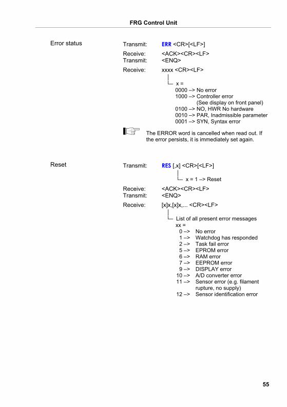
Transmit: ERR <CR>[<LF>] Receive: <ACK><CR><LF> Transmit: <ENQ> Receive: xxxx <CR><LF>
│ └─ x = 0000 –> No error 1000 –> Controller error (See display on front panel) 0100 –> NO, HWR No hardware 0010 –> PAR, Inadmissible parameter 0001 –> SYN, Syntax error
The ERROR word is cancelled when read out. If the error persists, it is immediately set again.
Transmit: RES [,x] <CR>[<LF>] │ └─ x = 1 –> Reset
Receive: <ACK><CR><LF> Transmit: <ENQ> Receive: [x]x,[x]x,... <CR><LF>
│ └─ List of all present error messages xx = 0 –> No error 1 –> Watchdog has responded 2 –> Task fail error 5 –> EPROM error 6 –> RAM error 7 –> EEPROM error 9 –> DISPLAY error 10 –> A/D converter error 11 –> Sensor error (e.g. filament rupture, no supply) 12 –> Sensor identification error
Error status
Reset
FRG Control Unit
56
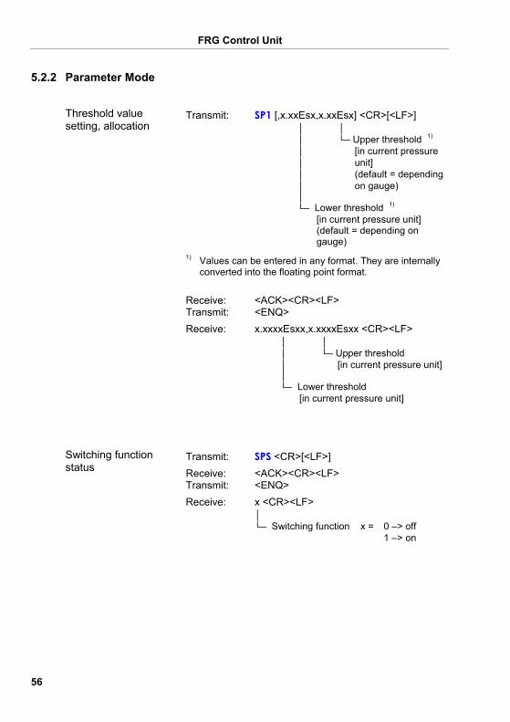
Transmit: SP1 [,x.xxEsx,x.xxEsx] <CR>[<LF>] │ │ │ └─ Upper threshold 1) │ [in current pressure │ unit] │ (default = depending │ on gauge) │ └─ Lower threshold 1) [in current pressure unit] (default = depending on gauge)
1) Values can be entered in any format. They are internally
converted into the floating point format. Receive: <ACK><CR><LF> Transmit: <ENQ> Receive: x.xxxxEsxx,x.xxxxEsxx <CR><LF>
│ │ │ └─ Upper threshold │ [in current pressure unit] │ └─ Lower threshold [in current pressure unit]
Transmit: SPS <CR>[<LF>] Receive: <ACK><CR><LF> Transmit: <ENQ> Receive: x <CR><LF>
│ └─ Switching function x = 0 –> off 1 –> on
5.2.2 Parameter Mode
Threshold value setting, allocation
Switching function status
FRG Control Unit
57
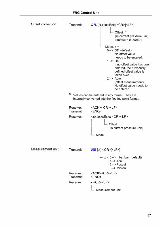
Transmit: OFS [,x,x.xxxEsx] <CR>[<LF>] │ │ │ └─ Offset 1)
│ [in current pressure unit] │ (default = 0.000E0) │ └─ Mode, x = 0 –> Off (default) No offset value needs to be entered. 1 –> On If no offset value has been entered, the previously defined offset value is taken over. 2 –> Auto (offset measurement) No offset value needs to be entered.
1) Values can be entered in any format. They are
internally converted into the floating point format. Receive: <ACK><CR><LF> Transmit: <ENQ> Receive: x,sx.xxxxEsxx <CR><LF>
│ │ │ └─ Offset │ [in current pressure unit] │ └─ Mode
Transmit: UNI [,x] <CR>[<LF>] │ └─ x = 0 –> mbar/bar (default) 1 –> Torr 2 –> Pascal 3 –> Micron
Receive: <ACK><CR><LF> Transmit: <ENQ> Receive: x <CR><LF>
│ └─ Measurement unit
Offset correction
Measurement unit
FRG Control Unit
58
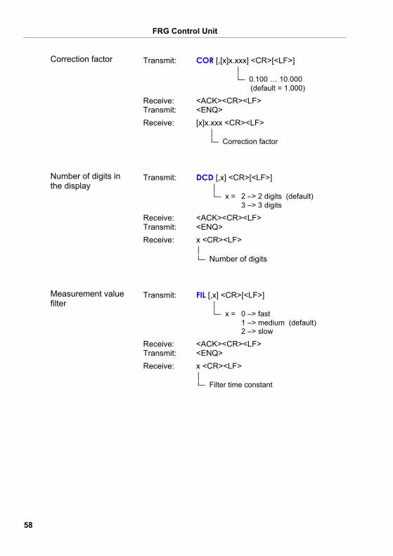
Transmit: COR [,[x]x.xxx] <CR>[<LF>] │ └─ 0.100 … 10.000 (default = 1.000)
Receive: <ACK><CR><LF> Transmit: <ENQ> Receive: [x]x.xxx <CR><LF>
│ └─ Correction factor
Transmit: DCD [,x] <CR>[<LF>] │ └─ x = 2 –> 2 digits (default) 3 –> 3 digits
Receive: <ACK><CR><LF> Transmit: <ENQ> Receive: x <CR><LF>
│ └─ Number of digits
Transmit: FIL [,x] <CR>[<LF>] │ └─ x = 0 –> fast 1 –> medium (default) 2 –> slow
Receive: <ACK><CR><LF> Transmit: <ENQ> Receive: x <CR><LF>
│ └─ Filter time constant
Correction factor
Number of digits in the display
Measurement value filter
FRG Control Unit
59
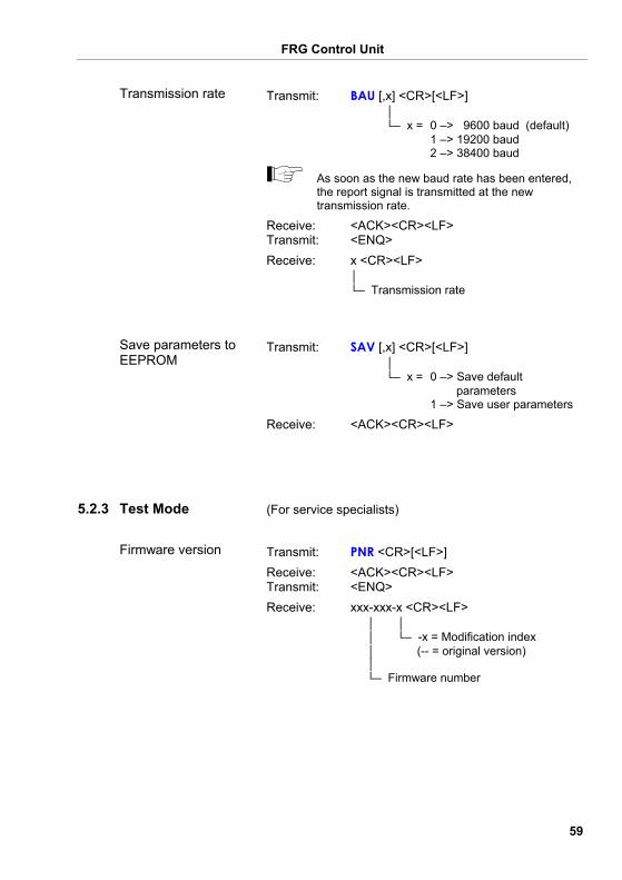
Transmit: BAU [,x] <CR>[<LF>] │ └─ x = 0 –> 9600 baud (default) 1 –> 19200 baud 2 –> 38400 baud
As soon as the new baud rate has been entered, the report signal is transmitted at the new transmission rate.
Receive: <ACK><CR><LF> Transmit: <ENQ> Receive: x <CR><LF>
│ └─ Transmission rate
Transmit: SAV [,x] <CR>[<LF>] │ └─ x = 0 –> Save default parameters 1 –> Save user parameters
Receive: <ACK><CR><LF>
(For service specialists)
Transmit: PNR <CR>[<LF>] Receive: <ACK><CR><LF> Transmit: <ENQ> Receive: xxx-xxx-x <CR><LF>
│ │ │ └─ -x = Modification index │ (-- = original version) │ └─ Firmware number
Transmission rate
Save parameters to EEPROM
5.2.3 Test Mode
Firmware version
FRG Control Unit
60
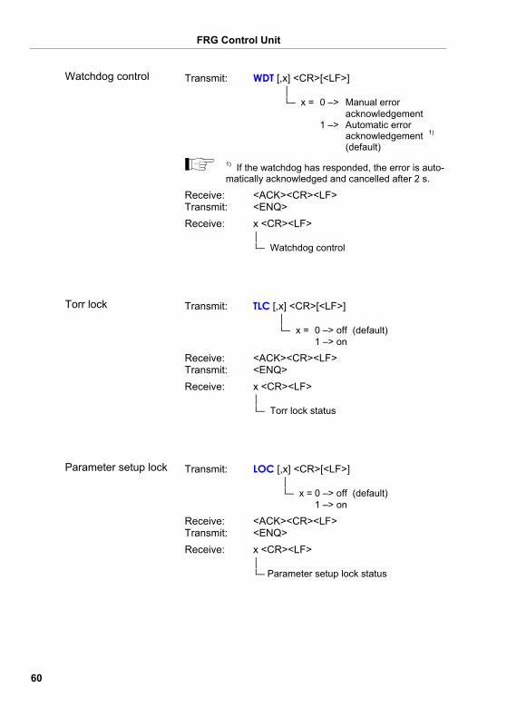
Transmit: WDT [,x] <CR>[<LF>] │ └─ x = 0 –> Manual error acknowledgement 1 –> Automatic error acknowledgement 1) (default)
1) If the watchdog has responded, the error is auto-matically acknowledged and cancelled after 2 s.
Receive: <ACK><CR><LF> Transmit: <ENQ> Receive: x <CR><LF>
│ └─ Watchdog control
Transmit: TLC [,x] <CR>[<LF>] │ └─ x = 0 –> off (default) 1 –> on
Receive: <ACK><CR><LF> Transmit: <ENQ> Receive: x <CR><LF>
│ └─ Torr lock status
Transmit: LOC [,x] <CR>[<LF>] │ └─ x = 0 –> off (default) 1 –> on
Receive: <ACK><CR><LF> Transmit: <ENQ> Receive: x <CR><LF>
│ └─ Parameter setup lock status
Watchdog control
Torr lock
Parameter setup lock
FRG Control Unit
61
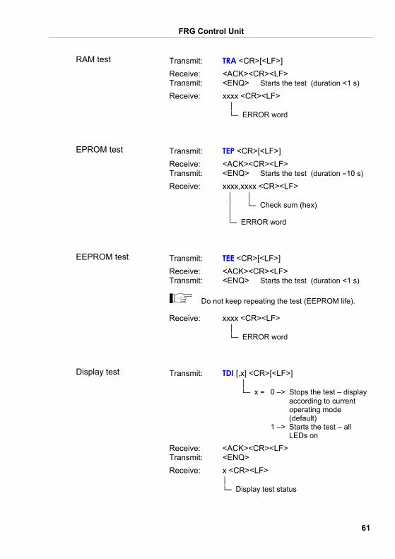
Transmit: TRA <CR>[<LF>] Receive: <ACK><CR><LF> Transmit: <ENQ> Starts the test (duration <1 s) Receive: xxxx <CR><LF>
│ └─ ERROR word
Transmit: TEP <CR>[<LF>] Receive: <ACK><CR><LF> Transmit: <ENQ> Starts the test (duration ≈10 s) Receive: xxxx,xxxx <CR><LF>
│ │ │ └─ Check sum (hex) │ └─ ERROR word
Transmit: TEE <CR>[<LF>] Receive: <ACK><CR><LF> Transmit: <ENQ> Starts the test (duration <1 s)
Do not keep repeating the test (EEPROM life).
Receive: xxxx <CR><LF> │ └─ ERROR word
Transmit: TDI [,x] <CR>[<LF>] │ └─ x = 0 –> Stops the test – display according to current operating mode (default) 1 –> Starts the test – all LEDs on
Receive: <ACK><CR><LF> Transmit: <ENQ> Receive: x <CR><LF>
│ └─ Display test status
RAM test
EPROM test
EEPROM test
Display test
FRG Control Unit
62
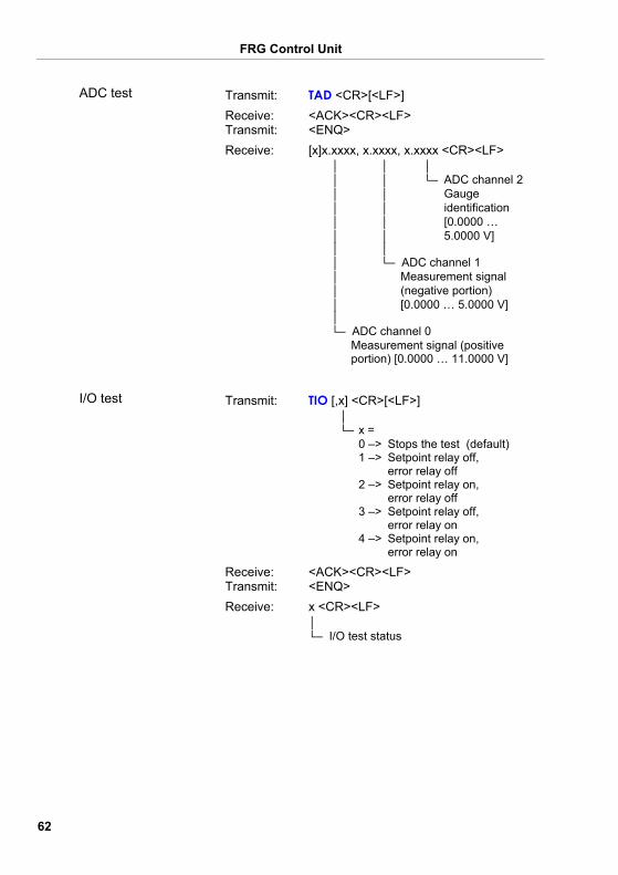
Transmit: TAD <CR>[<LF>] Receive: <ACK><CR><LF> Transmit: <ENQ> Receive: [x]x.xxxx, x.xxxx, x.xxxx <CR><LF>
│ │ │ │ │ └─ ADC channel 2 │ │ Gauge │ │ identification │ │ [0.0000 … │ │ 5.0000 V] │ │ │ └─ ADC channel 1 │ Measurement signal │ (negative portion) │ [0.0000 … 5.0000 V] │ └─ ADC channel 0 Measurement signal (positive portion) [0.0000 … 11.0000 V]
Transmit: TIO [,x] <CR>[<LF>] │ └─ x = 0 –> Stops the test (default) 1 –> Setpoint relay off, error relay off 2 –> Setpoint relay on, error relay off 3 –> Setpoint relay off, error relay on 4 –> Setpoint relay on, error relay on
Receive: <ACK><CR><LF> Transmit: <ENQ> Receive: x <CR><LF>
│ └─ I/O test status
ADC test
I/O test
FRG Control Unit
63
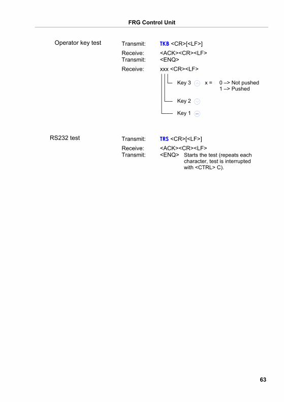
Transmit: TKB <CR>[<LF>] Receive: <ACK><CR><LF> Transmit: <ENQ> Receive: xxx <CR><LF>
│││ ││└─ Key 3 x = 0 –> Not pushed ││ 1 –> Pushed ││ │└── Key 2 │ └─── Key 1 para
Transmit: TRS <CR>[<LF>] Receive: <ACK><CR><LF> Transmit: <ENQ> Starts the test (repeats each character, test is interrupted with <CTRL> C).
Operator key test
RS232 test
FRG Control Unit
64
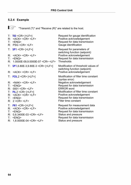
"Transmit (T)" and "Receive (R)" are related to the host.
T: TID <CR> [<LF>] R: <ACK> <CR> <LF> T: <ENQ> R: PSG <CR> <LF>
Request for gauge identification Positive acknowledgement Request for data transmission Gauge identification
T: SP1 <CR> [<LF>] R: <ACK> <CR> <LF> T: <ENQ> R: 1.0000E-09,9.0000E-07 <CR> <LF>
Request for parameters of switching function (setpoint) Positive acknowledgement Request for data transmission Thresholds
T: SP1,6.80E-3,9.80E-3 <CR> [<LF>] R: <ACK> <CR> <LF>
Modification of threshold values of switching function (setpoint) Positive acknowledgement
T: FOL,2 <CR> [<LF>] R: <NAK> <CR> <LF> T: <ENQ> R: 0001 <CR> <LF> T: FIL,2 <CR> [<LF>] R: <ACK> <CR> <LF> T: <ENQ> R: 2 <CR> <LF>
Modification of filter time constant (syntax error) Negative acknowledgement Request for data transmission ERROR word Modification of filter time constant Positive acknowledgement Request for data transmission Filter time constant
T: PR1 <CR> [<LF>] R: <ACK> <CR> <LF> T: <ENQ> R: 0,8.3400E-03 <CR> <LF> T: <ENQ> R: 1,8.0000E-04 <CR> <LF>
Request for measurement data Positive acknowledgement Request for data transmission Status and pressure Request for data transmission Status and pressure
5.2.4 Example
FRG Control Unit
65
6 Maintenance
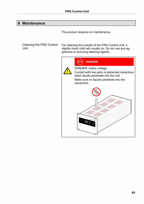
The product requires no maintenance.
For cleaning the outside of the FRG Control Unit, a slightly moist cloth will usually do. Do not use any ag-gressive or scouring cleaning agents.
DANGER
DANGER: mains voltage Contact with live parts is extremely hazardous when liquids penetrate into the unit. Make sure no liquids penetrate into the equipment.
Cleaning the FRG Control Unit
FRG Control Unit
66
7 Troubleshooting
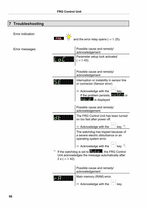
and the error relay opens (→ 25).
Possible cause and remedy/ acknowledgement
Parameter setup lock activated (→ 43).
Possible cause and remedy/
acknowledgement
Interruption or instability in sensor line or connector (Sensor error).
Acknowledge with the key. If the problem persists, or
is displayed Possible cause and remedy/
acknowledgement
The FRG Control Unit has been turned on too fast after power off.
Acknowledge with the key 1). The watchdog has tripped because of
a severe electric disturbance or an operating system error.
Acknowledge with the key 1). 1) If the watchdog is set to , the FRG Control
Unit acknowledges the message automatically after 2 s (→ 42).
Possible cause and remedy/ acknowledgement
Main memory (RAM) error.
Acknowledge with the key.
Error indication
Error messages
FRG Control Unit
67
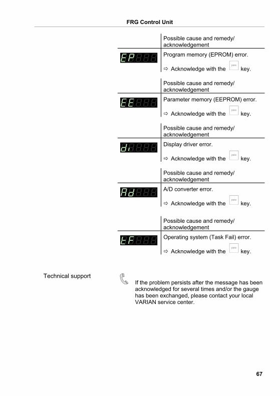
Possible cause and remedy/ acknowledgement
Program memory (EPROM) error.
Acknowledge with the key. Possible cause and remedy/
acknowledgement
Parameter memory (EEPROM) error.
Acknowledge with the key. Possible cause and remedy/
acknowledgement
Display driver error.
Acknowledge with the key. Possible cause and remedy/
acknowledgement
A/D converter error.
Acknowledge with the key.
Possible cause and remedy/ acknowledgement
Operating system (Task Fail) error.
Acknowledge with the key.
If the problem persists after the message has been acknowledged for several times and/or the gauge has been exchanged, please contact your local VARIAN service center.
Technical support
FRG Control Unit
68
8 Repair
Return defective products to your local VARIAN service center for repair. VARIAN assumes no liability and the warranty becomes null and void if repair work is carried out by the end-user or third parties.
9 Accessories
Ordering number
Adapter panel for installation into a 19" rack chassis adapter, height 3 U
FRG700ADPT
10 Storage
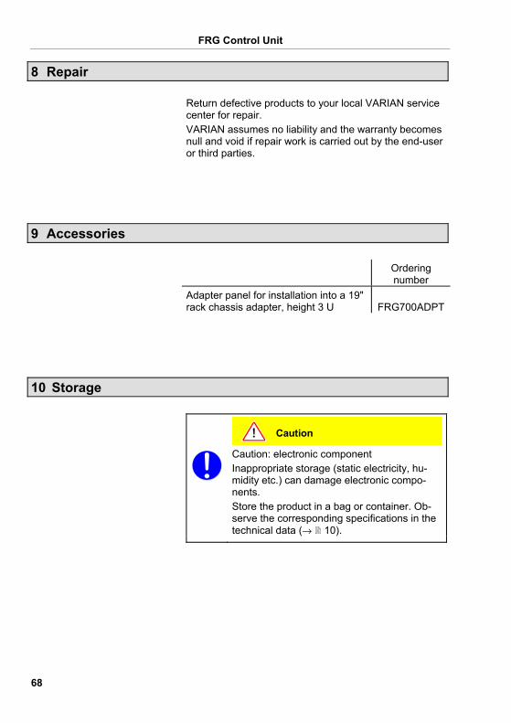
Caution
Caution: electronic component Inappropriate storage (static electricity, hu-midity etc.) can damage electronic compo-nents. Store the product in a bag or container. Ob-serve the corresponding specifications in the technical data (→ 10).
FRG Control Unit
69
11 Disposal
WARNING
WARNING: substances detrimental to the environment Products or parts thereof (mechanical and electric components, operating fluids etc.) can be detrimental to the environment. Dispose of such substances in accordance with the relevant local regulations.
After disassembling the product, separate its compo-nents according to the following criteria:
Such components must be separated according to their materials and recycled.
Such components must be separated according to their materials and recycled.
Separating the components
Non-electronic components
Electronic components
FRG Control Unit
70
Appendix
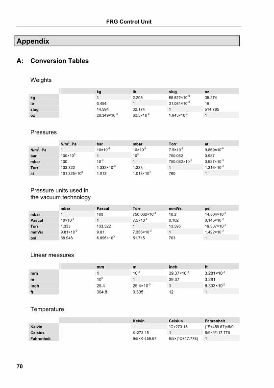
kg lb slug oz kg 1 2.205 68.522×10⁻³ 35.274
lb 0.454 1 31.081×10⁻³ 16
slug 14.594 32.174 1 514.785 oz 28.349×10⁻³ 62.5×10⁻³ 1.943×10⁻³ 1
N/m2, Pa bar mbar Torr at N/m2, Pa 1 10×10-6 10×10-3 7.5×10⁻³ 9.869×10⁻⁶ bar 100×103 1 103 750.062 0.987 mbar 100 10-3 1 750.062×10⁻³ 0.987×10⁻³ Torr 133.322 1.333×10⁻³ 1.333 1 1.316×10⁻³ at 101.325×10³ 1.013 1.013×10³ 760 1
mbar Pascal Torr mmWs psi mbar 1 100 750.062×10⁻³ 10.2 14.504×10⁻³ Pascal 10×10-3 1 7.5×10⁻³ 0.102 0.145×10⁻³ Torr 1.333 133.322 1 13.595 19.337×10⁻³ mmWs 9.81×10⁻² 9.81 7.356×10⁻² 1 1.422×10⁻³ psi 68.948 6.895×10³ 51.715 703 1
mm m inch ft mm 1 10-3 39.37×10⁻³ 3.281×10⁻³ m 103 1 39.37 3.281 inch 25.4 25.4×10⁻³ 1 8.333×10⁻² ft 304.8 0.305 12 1
Kelvin Celsius Fahrenheit Kelvin 1 °C+273.15 (°F+459.67)×5/9 Celsius K-273.15 1 5/9×°F-17.778 Fahrenheit 9/5×K-459.67 9/5×(°C+17.778) 1
A: Conversion Tables
Weights
Pressures
Pressure units used in the vacuum technology
Linear measures
Temperature
FRG Control Unit
71
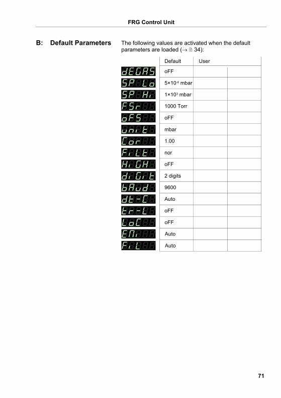
The following values are activated when the default parameters are loaded (→ 34):
Default User
mbar
oFF
1000 Torr
1×10³ mbar
5×10⁻⁴ mbar
oFF
1.00
nor
oFF
9600
Auto
oFF
2 digits
oFF
Auto
Auto
B: Default Parameters
FRG Control Unit
72
If your FRG Control Unit firmware needs updating, e.g. for implementing a new gauge type, please contact your local VARIAN service center.
Most of the settings you may have defined in the Pa-rameter and Test mode will not be affected by a firm-ware update. To be sure, note your parameter settings before upgrading the firmware (→ 71).
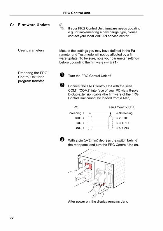
Turn the FRG Control Unit off
Connect the FRG Control Unit with the serial COM1 (COM2) interface of your PC via a 9-pole D-Sub extension cable (the firmware of the FRG Control Unit cannot be loaded from a Mac).
PC FRG Control Unit
2 TXDRXD3 RXDTXD5 GNDGND
Screening Screening
With a pin (ø<2 mm) depress the switch behind the rear panel and turn the FRG Control Unit on.
After power on, the display remains dark.
C: Firmware Update
User parameters
Preparing the FRG Control Unit for a program transfer
FRG Control Unit
73
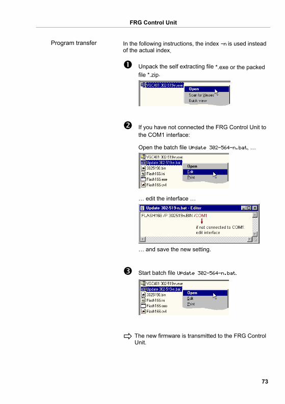
In the following instructions, the index -n is used instead of the actual index.
Unpack the self extracting file *.exe or the packed file *.zip.
If you have not connected the FRG Control Unit to the COM1 interface:
Open the batch file Update 302-564-n.bat, …
… edit the interface …
… and save the new setting.
Start batch file Update 302-564-n.bat.
The new firmware is transmitted to the FRG Control Unit.
Program transfer
FRG Control Unit
74
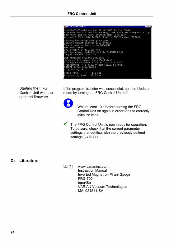
If the program transfer was successful, quit the Update mode by turning the FRG Control Unit off.
Wait at least 10 s before turning the FRG Control Unit on again in order for it to correctly initialize itself.
The FRG Control Unit is now ready for operation. To be sure, check that the current parameter settings are identical with the previously defined settings (→ 71).
[1] www.varianinc.com
Instruction Manual Inverted Magnetron Pirani Gauge FRG-700 tqna48e1 VARIAN Vacuum Technologies MA, 02421 USA
Starting the FRG Control Unit with the updated firmware
D: Literature
FRG Control Unit
75
A/D converter test 45 Accessories 68 Baud rate 39 Calibration factor → Correction factor Cleaning 65 Communication
Example 64 Mnemonics 52 RS232C- 48
Connectors CONTROL 24 mains power 21 RS232 26 SENSOR 23
Contact positions 25 Contents 6 CONTROL connector 24 Conversion 70 Correction factor 37 Default parameters 71
Loading 34 Default settings 71 Display
resolution 39 Display test 45 Disposal 69 EEPROM 44 EPROM test 44 Error messages 66 Factory settings 71 Filter 37 Firmware
update 72 version 4, 42
Front panel 27 display 27 operator keys 27
Full Scale → Measurement range Gauge
identification 31 Gauge connector 23 Gauge parameters
measurement value filter 37 Gauges 10 General parameters
display resolution 39 pressure units 36
I/O test 47 Identification of the gauge 31 Installation 14 Interface → RS232C Literature 74 Mains power connector 21 Maintenance 65 Measurement mode
displaying the gauge identification 31
Measurement units → Pressure units Measurement value filter 37 Mnemonics → Communication Mode → Operating modes Operating modes
Measurement mode 30 overview 29 Parameter mode 32 Program transfer mode 72 Test mode 40
Operation power off 28 power on 28
Parameter mode 32 correction factor 37 display resolution 39 measurement value filter 37 pressure units 36 switching thresholds 34 transmission rate 39
Parameter setup lock 43 Pin assignment
CONTROL 25 RS232 26 SENSOR 24
Power connector 21 Power off 28 Power on 28 Pressure units 36 Program → Firmware RAM test 43 Repair 68 RS232C
interface connector 26 Serial interface 26 Technical data 13 Test 47
E: Index
FRG Control Unit
76
Safety 8 Scope of Delivery 5 SENSOR connector 23 Serial interface → RS232C Storage 68 Switching function 34 Symbols 8 Technical data 10 Test 44 Test mode
A/D converter test 45 Display test 45 EPROM test 44 Firmware version 42
I/O test 47 parameter setup lock 43 RAM test 43 RS232C test 47 Torr lock 43 Watchdog 42
Thresholds 34 Torr lock 43 Transmission rate 39 Troubleshooting 66 Units → Pressure units Update 72 Watchdog 42
FRG Control Unit
77
EC Declaration of Conformity
We, VARIAN, hereby declare that the equipment mentioned below complies with the provisions of the Directive relating to electrical equipment designed for use within certain voltage limits 2006/95/EC and the Directive relating to electromagnetic compatibility 89/336/EEC.
FRG Control Unit
FRG700CNTR1
Harmonized and international/national standards and specifications: • EN 61010-1 (Safety requirements for electrical equipment
for measurement, control and laboratory use) • EN 50081-1 (EMC: generic emission standard) • EN 50082-2 (EMC: generic immunity standard)
Varian Vacuum Technologies, USA 9 December 2008
Frederick C. Campbell Operations Manager
Product
Part number
Standards
Signatures

FRG Control Unit
78
Notes

FRG Control Unit
79
Notes

Varian Vacuum Technologies 121 Hartwell Avenue Lexington, MA, 02421 USA Tel: (781) 861 7200 Fax: (781) 861 5437
Original: English [email protected]
t qnb01e1 www.varianinc.com