![City Research Online · According to Ofcom [3] research, there is more than 150MHz of interleaved spectrum in over 50% of locations and 100MHZ of interleaved spectrum in 90% of locations](https://static.fdocuments.us/doc/165x107/5fc82cec2dbeb475fa56945a/city-research-online-according-to-ofcom-3-research-there-is-more-than-150mhz.jpg)
FREQUENCY ELECTRONICS, INC.freqelec.com/space/space-fei_capabil_07-06.pdfFREQUENCY ELECTRONICS, INC....
72
1 FREQUENCY ELECTRONICS, INC. World Leader in High Precision Time & Frequency Control Technology for Space Applications Olie Mancini 07-06
-
Upload
vuongthuan -
Category
Documents
-
view
214 -
download
0
Transcript of FREQUENCY ELECTRONICS, INC.freqelec.com/space/space-fei_capabil_07-06.pdfFREQUENCY ELECTRONICS, INC....

1
FREQUENCY ELECTRONICS, INC.
World Leader in High Precision Time & Frequency Control Technology for Space Applications
Olie Mancini 07-06

2
Frequency Electronics, Inc.U.S. Headquarters
• ISO 9001 Registered• Strong Balance Sheet• Website: www.freqelec.com• NASDAQ: Stock Symbol FEIM
Founded in Founded in 19611961Modern FacilityModern Facility–– 100,000 sqft: Laboratory, Engineering and Production Space100,000 sqft: Laboratory, Engineering and Production Space
Mitchel Field, New YorkMitchel Field, New York275 Employees275 Employees–– Professional and Technical Staff: 150Professional and Technical Staff: 150
3
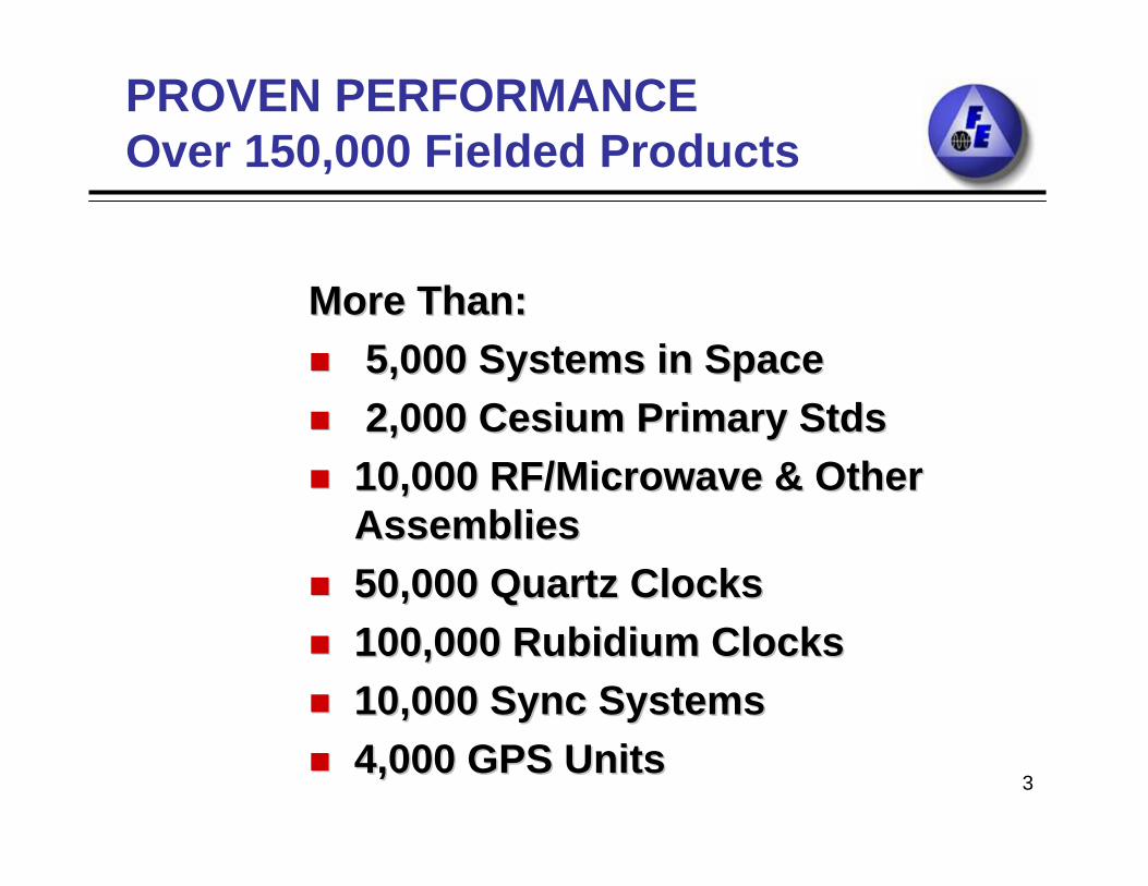
More Than:More Than:5,000 Systems in Space5,000 Systems in Space2,000 Cesium Primary 2,000 Cesium Primary StdsStds
10,000 RF/Microwave & Other 10,000 RF/Microwave & Other AssembliesAssemblies50,000 Quartz Clocks50,000 Quartz Clocks100,000 Rubidium Clocks100,000 Rubidium Clocks10,000 Sync Systems10,000 Sync Systems4,000 GPS Units4,000 GPS Units
PROVEN PERFORMANCEOver 150,000 Fielded Products
4
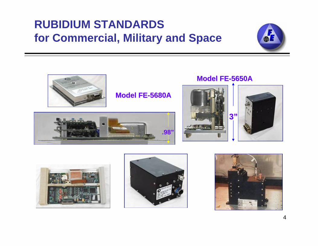
RUBIDIUM STANDARDSfor Commercial, Military and Space
33””
Model FEModel FE--5650A5650A
Model FEModel FE--5680A5680A
.98.98””

5
Precision Crystals and OscillatorsFrom Raw Materials
For For Commercial Telecommunications and Military ApplicationsCommercial Telecommunications and Military Applications
5 MHz 55 MHz 5th th
Overtone Overtone CrystalCrystal
10 MHz 310 MHz 3th th
Overtone Overtone CrystalCrystal
““FEFE--205A Series205A Series””StateState--ofof--thethe--artart
Super Precise OscillatorsSuper Precise Oscillators(Poor Man(Poor Man’’s Rubidium!)s Rubidium!)
ShockShock--Mounted Mounted Precision Oscillator Precision Oscillator for Aircraft for Aircraft ApplicationsApplications

6
Master ClockQuartz orRubidium
Frequency Generation,
Synthesis andDistribution
5 MHz to 42 GHz
Digital Systems Etc.
Up/Down Converters,Receivers
DC to DCConverters
To Transmitter
GPS ReceiverWith Low Phase Noise Quartz or
RubidiumOscillator
Frequency Distribution Amplifier
fo
OtherFrequency Generation
And Synthesis
Ground Station
Satellite
Provided by FEI
Space Technologies and Capabilities

7
Space Technologies
KU BAND UP/DOWN CONVERTER
DC TO DC CONVERTER MODEL FE-302A
Triple Redundant Quartz based Clocks and Frequency Distribution
HybridsHybrids
FEFE--4220A Series OCXO4220A Series OCXO

8
FREQUENCY ELECTRONICS, INC. SPACE CUSTOMER BASE
• Alcatel• Alenia Spazio• Aerojet• Astrium• Ball Aerospace• Boeing/Hughes Space• ITT• JPL
• Lockheed Martin• NASA• Raytheon• Space Systems
Loral• Northrop-
Grumman/TRW• DoD/MILITARY

9
Alcatel KoreaSat 5; Syracuse I,II Telephony 1 & 2; Intelsat 9, MTSat; Worldstar;XM Radio 1,2,3,4
Alenia SICRAL 1, 1B; ARTEMIS; EMSJPO-GPSIII ATAFS-GPS III RbHughes/Boeing WGS 1,2,3,4,5,6
Milstar, UHF, AnikNothrop-Grumman/TRW AEHF 1,2,3; NPOESSS/Loral TerreStar, ICO,
GlobalstarISRO NSAT 2Raytheon DefenseDoD Secure Com JPL Mars Mission Orbital Sciences GCCS (WAAS)COM-DEV CascadeBall Aerospace Kepler
RECENT SPACE ACTIVITIESFREQUENCY REFERENCE UNITS and SYNTHESIZERS (1 MHz to 44GHz)

10
RECENT SPACE ACTIVITIES
• Frequency Translators / ReceiversCTI IndostarSS/Loral EutelsatOrbital Sciences GCCS (WAAS)
• DC/DC ConvertersAerojet SSMISSS/Loral N-Star, Thaicom, YamalAlcatel Syracuse, XM Radio,
Numerous Other
• HybridsHughes VariousSS/Loral Various

11
FREQUENCY = 1 MHz to 44 GHz
TYPESDirect = Multiply, Divide, MixIndirect = Phase Locked, VCXO, DRO
LOW NOISE = 170 dBc / Hz NOISE FLOOR
LOW SPURS = -110 dBc
CROSS-STRAPPED CONFIGURATIONS
OTPUTS: High Isolation 1 to 60
Frequency Reference Units and Synthesizers
12
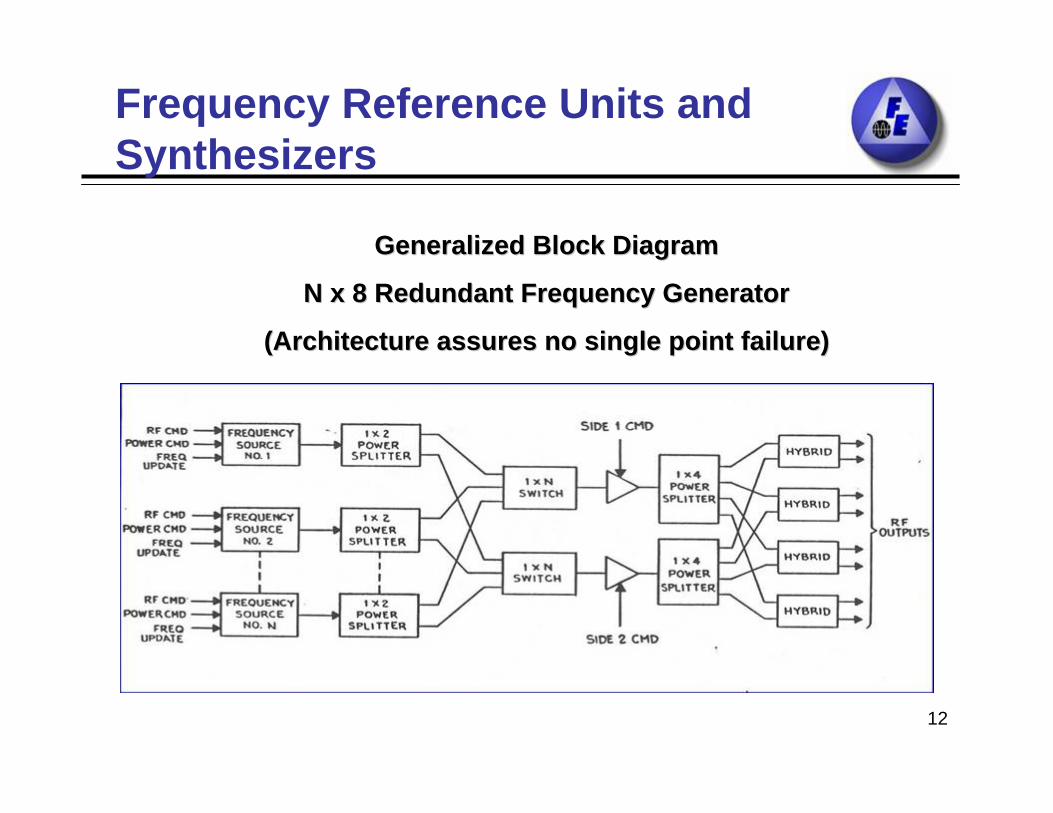
Frequency Reference Units and Synthesizers
Generalized Block DiagramGeneralized Block Diagram
N x 8 Redundant Frequency GeneratorN x 8 Redundant Frequency Generator
(Architecture assures no single point failure)(Architecture assures no single point failure)

13
Frequency Reference Units and Synthesizers
Triple Redundant Ultra Stable Oscillator (USO) and Triple Redundant Ultra Stable Oscillator (USO) and Distribution AssemblyDistribution Assembly
Syracuse and Syracuse and KoreaSatKoreaSat Programs: 60 Isolated Programs: 60 Isolated OutputsOutputs

14
Local Oscillator, Eutelsat II
Model FE-5140A
Triple Redundant Quartz Master Oscillator
WGS, WORLDSTAR, XM Radio and numerous other space programs
Frequency Reference Units and Synthesizers

15
Frequency Range 20MHz to 145 MHz
Low Phase noise
Excellent Temp. Stability < +2 x 10⁻⁷
-100C to +600C Operating
Low Aging +1 ppm for life
Radiation Immunity 100 Krads
Highly Reliable: Over 20 years of space service with zero failures
Small size and light weight
Frequency Reference Units and Synthesizers
OCXO Model FE-4220A

16
Frequency Reference Units and Synthesizers
Triple Redundant Precision Master Oscillator
Flying on numerous Military and NASA satellites
MILSTAR, UHF/EHF, POLARSAT, and numerous other programs

17
Frequency Reference Units and Synthesizers
ACTS
Frequency Generator FE-5150A
5 MHz to 6.8 GHz; Fully Redundant; Includes DC / DC Converter
18
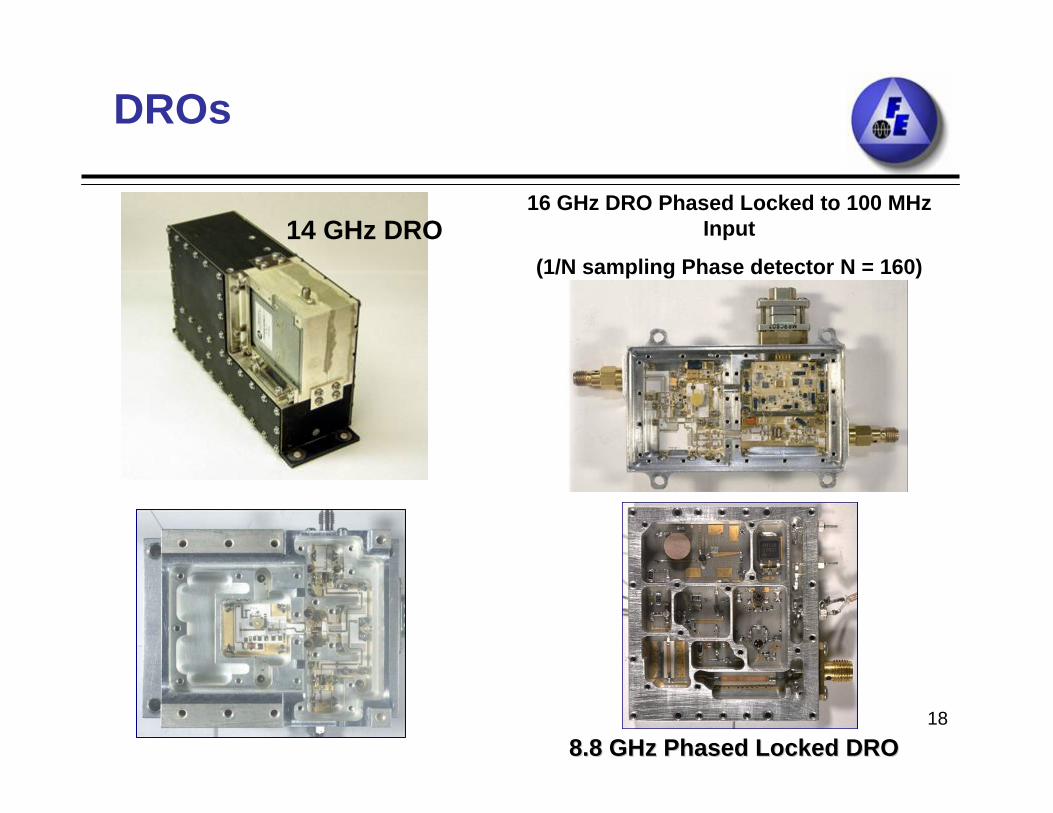
DROs
16 GHz DRO Phased Locked to 100 MHz Input
(1/N sampling Phase detector N = 160)14 GHz DRO
8.8 GHz Phased Locked DRO8.8 GHz Phased Locked DRO

19
Typical Phase Noise 14 GHz DRO

20
• PHASE LOCKED DRO– Output Frequency: 14.16GHz– Reference Frequency: 80MHz– Multiplication: 177– Output Power: +13 dBm, Dual Outputs– Spurious Signals: -80 dBc– DC Current: 300 mA at +15V– Phase Noise: -112 dBc/Hz (TYP) @ 1KHz to 100KHz– Qualified on space station– 15 year life– MMIC, MIC and SMT Technology
DRODRO

21
• FREE RUNNING DRO– Frequency: 13.775GHz– Stability: ±30 ppm/yr– Output Power: 0dBm– Spurious Signals: -60 dBc– Phase Noise (dBc/Hz): -105 at 100kHz
-120 at 1MHz– DC Current: 50mA at +15V
• Qualified on Space Station• Switchable Output, -90dB Isolation• MIC Construction
DRO
22
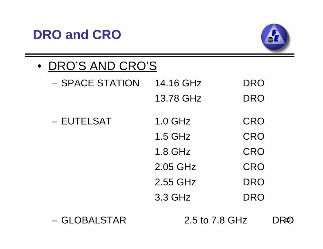
• DRO’S AND CRO’S– SPACE STATION 14.16 GHz DRO
13.78 GHz DRO
– EUTELSAT 1.0 GHz CRO1.5 GHz CRO1.8 GHz CRO2.05 GHz CRO2.55 GHz DRO3.3 GHz DRO
– GLOBALSTAR 2.5 to 7.8 GHz DRO
DRO and CRO

23
•Delivered and qualified package contains: DRO, Synthesizer and EPC
•Assembly has been qualified over the frequency range of 700 MHz to 18.2 GHz
•The DRO section remains identical except for scaling the actual “puck/resonator” and loop parameters to match requested frequencies
Multiple Frequency SourcesPackaging Configurations
f0 Input
RFI Filter DC/DC Converter Regulator
RF Output
35V to 100V DC Bus Input
Synthesizer DRO
EPC

24
Multiple Frequency SourcesPackaging Configurations
SMAFEMALE
4.20 [106.7]
3.70 [94.0]
.60 [15.2]
2.48 [62.9]
4.95 [125.7]
1.88 [47.6]
4.35 [110.5]
5.50 [139.7]
•Dual DC/DC Converters
•Dual Frequency Synthesizer
•Dual DRO
•Output frequencies from 1GHz to 17GHz

25
Multiple Frequency SourcesPackaging Configurations
•Dual Ultra Stable 50 MHz OCXO
•Dual DC/DC Converter
•Multiple Frequency Generation: 100MHz to 8GHz
•Telemetry and Command

26
Multiple Frequency SourcesPackaging Configurations
•Seven output frequencies 1GHz to 18GHz generated from 10 MHz
•DC/DC Converter
•Telemetry and Command

27
THESE ASSEMBLIES, DESIGNED FOR CUSTOM APPLICATIONS, COMBINE MANY TECHNOLOGIES TO PERFORM A COMPOSITE
COMPLEX FUNCTION. USED IN BOTH SPACE AND GROUND ENVIRONMENTS, UNITS OFTEN
INCLUDE POWER SUPPLIES, FREQUENCY GENERATORS AND SYNTHESIZERS, INTERFACE COMMAND AND TELEMETRY
CAPABILITY, SUBASSEMBLIES, AND REDUNDANT OPERATION.
FREQUENCY TRANSLATORS / RECEIVERS

28
UPCONVERTERS
DOWNCONVERTERS
PIN ATTENUATORS
GAIN CONTROL
TEMPERATURE COMPENSATION
CUSTOM TELEMETRY AND CONTROL
Frequency Translators/ReceiversRF to Ka-Band
Example of µWave Assembly Used in Up/Down Converters
•Up-Converters and Down-Converters available form RF to Ka-Band

29
REDUNDANT CONFIGURATIONS
INTERNAL/EXTERNAL LO
CONSTRUCTIONDISCRETE
MMIC
SMT ON ALUMINA SUBSTRATES
SMT ON SOFT BOARD
Frequency Translators/Receivers

30
Examples of Receiver components
8.8 GHz Phased Locked DRO8.8 GHz Phased Locked DRO
Low Noise AmplifiersLow Noise Amplifiers

31
INDOSTAR X-BANDRECEIVER
••INPUT FREQUENCY: 8.8 GHzINPUT FREQUENCY: 8.8 GHz••OUTPUT FREQUENCY: 2.2 GHzOUTPUT FREQUENCY: 2.2 GHz••BANDWIDTH: 150 MHzBANDWIDTH: 150 MHz••NOISE FIGURE: 1.6 dBNOISE FIGURE: 1.6 dB••INTERCEPT POINT: +30 dBmINTERCEPT POINT: +30 dBm••DC POWER: 11 WATTSDC POWER: 11 WATTS••WEIGHT: 3.2 kgWEIGHT: 3.2 kg
THIS IS A REDUNDANT UNIT OPERATING DIRECTLY THIS IS A REDUNDANT UNIT OPERATING DIRECTLY FROM THE SPACECRAFT BUS. IT IS FULLY CROSS FROM THE SPACECRAFT BUS. IT IS FULLY CROSS STRAPPED AND COMPUTER COMMANDABLE.STRAPPED AND COMPUTER COMMANDABLE.

32
BLOCK DIAGRAMC to S-BAND RECEIVER

33
DSP SHF RECEIVER
PIN:PIN: --48 THRU 48 THRU --117 dBm117 dBmRF INPUT FREQUENCY:RF INPUT FREQUENCY: 5.5 5.5 ±± 1.1 GHz1.1 GHzLOCAL OSCILLATORSLOCAL OSCILLATORS
XX--BANDBAND 9.18 GHz9.18 GHzCC--BANDBAND 3.696 GHz3.696 GHzOTHEROTHER 53.3/13.3 MHz53.3/13.3 MHz
OUTPUTSOUTPUTSCHANNEL ACHANNEL A 7.7 kHz 7.7 kHz ±± 900 Hz @ 1V PEAK900 Hz @ 1V PEAKCHANNEL BCHANNEL B 14.4 14.4 kHz kHz ±± 900 Hz @ 1V PEAK900 Hz @ 1V PEAK
DC POWER:DC POWER: +15V, +15V, --15V @ <7.3W15V @ <7.3W

34
DSP SHF RECEIVERBLOCK DIAGRAM

35
GCCS (WAAS) RECEIVER
L-band payload
• Part of the U.S FAA Geostationary Communications and Control Segment (GCCS) program.
•Galaxy 15 relays GPS navigation to in-flight aircraft, providing highly accurate guidance to pilots at airports and airstrips
Galaxy 15

36
GCCS (WAAS) RECEIVERBLOCK DIAGRAM

37
GCCS (WAAS) Receiver Subsystem

38
GCCS (WAAS) RECEIVERBLOCK DIAGRAM
• INPUT FREQUENCY (GHz) 6.6• NOISE FIGURE (dB) 1.2• RECEIVER GAIN (dB) 67 – 82• LNA GAIN (dB) 52• BANDWIDTH MHz 75• TEMPERATURE RANGE 0C -25 TO +67• DC POWER (WATTS) 27 (1 LNA)• RELIABILITY 1250 FITS (15
years)• GROUP DELAY (nsec) 0.40• OIP3 (dBm) +22

39
FREQUENCY TRANSLATORSFREQUENCY TRANSLATORS

40
Frequency Translators/Receivers

41
Frequency Translators/Receivers
TDRSS Frequency Converters

42
Frequency Translators/Receivers
SATCOMSATCOM
Receiver FamilyReceiver Family
Ka Ka –– BandBand
Up and Down Up and Down ConverterConverter

43
Other Building Blocks for Space Applications

44
• Rubidium Clock System on board MILSTAR Space Craft since 1994 – All frequencies and timing for the MILSTAR
satellites are derived from the RMO – Low Drift < 3 x 10-14 / day– Inherently insensitive to radiation effects– Designed for low single event upset
• Rubidium Clock System and Synthesizer on board AEHF
Rubidium Clocks in Space

45
Rubidium Clocks in Space
MILSTARMILSTAR
Rubidium Master Oscillator SN 003 Rubidium Master Oscillator SN 003
••Total of 19 systems delivered to MILSTARTotal of 19 systems delivered to MILSTARExcellent Excellent
performance performance
in spacein space
Aging Rate:Aging Rate:
≈≈ 3x103x10--1414/day/day

46
On Orbit Data, Milstar RMO
y = 3E-14/day-2E-10
-1E-10
0
1E-10
2E-10
3E-10
Nov-95
Nov-96
Nov-97
Nov-98
Nov-99
Nov-00
Nov-01
Time
Freq
uenc
y O
ffse
t (d
elta
f/f)
Rubidium Clocks in Space

47
Rubidium Clocks in Space
AEHFAEHF
Advanced EHF Space System consisting of:
– Triple Redundant Rubidium Atomic Standards
– Triple Redundant Precision Quartz Oscillators
– Double Redundant Multiple Frequency RF Synthesizers
– Triple Redundant DC/DC Converters
– Triple Redundant Mil-Std-1553B Serial Interface

48
Rubidium Clocks in Space
GPS IIIFEI has been awarded a contract from the Air Force for Advanced Technology Atomic Frequency Standard (ATAFS) for GPS III

49
TYPES– Crystal 1MHz to 150MHz
– SAW 200 MHz to 1100 MHZ
– Helical 100MHz to 2GHz
– Cavity 1GHz to 39GHz
– Stripline 1GHz to 15GHz
FILTERS

50
TYPICAL PERFORMANCE
ORDERINPUT(MHz)
OUTPUT(MHz)
SPURIOUS(dBc) TYPE
X10 125 1,250 -65 Transistor,Efficient
X5 100 500 -40 Balanced,Low Noise
X5 1,120 5,600 -70 SRDX3 13,000 39,000 -30 Varactor
Designed for low noise spacecraft applications. These devices are available as integrated subassemblies incorporating Amplifiers, Isolators, and Filters. Active and step-recovery Diode techniques are used.
FREQUENCY MULTIPLYERS

51
DC /DC POWER CONVERTERS
ModelModel
FEFE--302A302A
3.53.5””
AeroAero--jetjet AMSUAMSU
100W 18 outputs100W 18 outputs
MTSAT 2MTSAT 2
20W, +20V, +15V, 20W, +20V, +15V, --15V15V

52
POWER OUTPUTS UP TO 200W
BUS INPUTS = 20V TO 100V
BASE-PLATE OPERATING TEMPERATURE UP TO 80C
STANDARD HYBRID DESIGNS FOR CONVERTER CONTROLLER AND LINEAR REGULATORS
CUSTOM MAGNETIC ELEMENT IN-House CAPABILITY
RADIATION HARDENED COMPONENTS AND CIRCUITS
ISOLATED AND NON-ISOLATED TELEMETRY SIGNALS AVAILABLE FROM INPUT AND/OR OUTPUT BUS.
DC /DC POWER CONVERTERS

53
• FEI has a long history of producing high reliability space-qualified dc-dc converters for numerous applications.
• FEI designs and manufactures dc-dc converters as:– stand-alone product – for integration into a total system solution. – Standard products are customized to an application’s specific requirements.
• Ability to adapt product to meet most customers’ requirements because of ;– modular pc board designs – hybrid building blocks
• Vertically integrated design and manufacturing process for total quality and reliability control
– power magnetics are custom designed and manufactured – proprietary hybrids in-house designed and manufactured to deliver superb,
proven and repeatable performance • 90 - 95% of all critical control and power circuitry is located inside the hybrid
DC-DC CONVERTER OVERVIEW & HERITAGE

54
DC-DC CONVERTER BLOCK DIAGRAM

55
DC-DC CONVERTER

56
The package measures 3.9 x 1.56 x 0.63 in. which includes a built-in EMI filter, multi-stage output filters, input undervoltage and output short circuit protection, regulation to 1%, is radiation hardened and has a power density of 6.7 watts per cubic inch.
DC-DC CONVERTER OUTLINE DRAWING

57
DC-DC CONVERTER PACKAGING DETAIL

58
DC-DC CONVERTER PACKAGING PHOTO

59
• FEI’s converters are radiation hardened – use of components such as radiation hardened switching power mosfets. – components are further protected by internal hybrid package (all of control
circuit and most power components)– the outer chassis.
• Package design(s) insure protection and guaranteed performance over mission life from:
– accumulated low dose radiation, – single event upset, – single event burnout etc.
Radiation Hardening
60
• Converters designed with – multiple stages of output filtering to achieve lowest noise possible while adhering
to size and weight constraints. – filters are designed to reduce switching fundamental frequency noise as well as
switching spike noise which contains many harmonics– Feed-thru filters may be additionally employed to eliminate switching spike noise.
• FEI’s chassis designs are optimized to allow the converters to meet the most stringent radiated emissions and susceptibility criteria
– use of pot-core magnetics which provide inherent shielding by design.
• In lower power converters, the aluminum chassis is designed to be emission “tight” by utilizing a laser welded chassis.
• In higher power converters, the chassis consists of hollowed out tub design with a recessed cover.
• These designs minimize gaps which could “leak” causing a radiated emission failure. The same design coupled with the use of spot shielding when required allows FEI to meet radiated susceptibility specification without difficulty.
EMI CAPABILITIES

61
RELIABILITY
• All designs are proven by analysis and test.
• Among the analyses which are performed on all converter designs include but are not limited to:
– electrical component stress– parametric worst-case analysis– thermal stress– radiation– reliability– mechanical – FMECA

62
BUILD TO SPECIFICATION OR BUILD TO PRINT
ANALOG, RF AND MicroWave FUNCTIONS
LOW AND HIGH POWER
THIN FILM AND THICK FILM TECHNOLOGY
EUTECTIC AND EPOXY CHIP AND SUBSTRATE MOUNTING
WIRE AND RIBBON BONDING
CUSTOM HYBRIDS

63
CUSTOM HYBRIDSHYBRIDS
64
WHY FEIFor Space Programs
• LEGACY: Extensive statistical data on performance of products in space– 5000 Systems in Space– Over 120 Satellite Programs
• PRODUCTS: Deep product line of Space Products
• HERITAGE: Clocks on board space craft since 1964
65
• LOW RISK AND PERFORMANCE COMPLIANCE
– All critical components e.g. SC-cut, AT-cut, FC-cut crystals, hybrid assemblies, and magnetic are manufactured at FEI from raw material to finished products
– Usage of “Premium Q Swept Quartz” or radiation hardened quartz material
– Usage of crystals exhibiting monotonically-positive aging slope (radiation offsets the positive aging trend of quartz)
– All critical components e.g. glass lamps, resonance cells, RF cavities and magnetic for Rubidium Atomic Standards are manufactured at FEI from raw material to finished products.
WHY FEIFor Space Programs

66
Statistical Data AnalysisAssures Mission Success
• Clocks on board numerous space craft since 1963 have accumulated millions of hours of data and have provided extensive statistical data in terms of: – reliability, – performance, – radiation effects, – corrections, – drift rates and other important parameters
• Quartz, Rubidium and Cesium Clocks have been supplied in various forms and in various redundant modes

67
Statistical Data AnalysisAssures Mission Success
• Examples of Quartz Clocks aging on-orbit:– Argos (6 clocks) ≈ 6 – 9 x 10-12/day after 5 years – Voyager (2 satellites) ≈ 3.4 x 10⁻¹²/day after 10 years (not in Earth’s orbit)– Fleet Sat Com (13 sat) ≈ 2 – 4.4 x 10⁻¹²/day after 15 years – MILSTAR ≈ 2 x 10-13 / day after 8 years
• Rubidium Atomic Standards aging on-orbit:Rubidium Clocks have been flying on MILSTAR since 1994 with continuous gathering and analysis of statistical data.– The estimated drift / day for Rb is < 3 x 10-14 / day
• Cesium clocks and other space products have also been flying fornumerous hours and relevant data has been tabulated and analyzed

68
SPECIAL EXPERTISE
• ISO 9001 REGISTERED.• QUALITY SYSTEMS AND FEI PROCESS
AND PROCEDURES HAVE BEEN APPROVED BY MANY U.S. AND EUROPEAN COMPANIES.
• REQUIRED ANALYSIS: WORST CASE, THERMAL, RADIATION, ETC.
• PARTS AND MATERIAL SELECTION, SCREENING, QUALIFICATION AND AQUISTION

69
Quality, Technology, Performance
QUALITYQUALITY - First and foremost priority in the Frequency First and foremost priority in the Frequency Electronics Corporation Electronics Corporation
–– ISO 9001 certified ISO 9001 certified
––Integrated Corporate Wide Quality Awareness Program Integrated Corporate Wide Quality Awareness Program
––On time deliveriesOn time deliveries
TECHNOLOGYTECHNOLOGY -- Frequency Electronics Inc. has set a Frequency Electronics Inc. has set a benchmark for highly reliable precision Quartz Oscillators benchmark for highly reliable precision Quartz Oscillators Rubidium and Cesium Atomic Standard.Rubidium and Cesium Atomic Standard.
PERFORMANCE PERFORMANCE -- Unmatched by any competitor for Unmatched by any competitor for precision time/frequency systems in applications for land, precision time/frequency systems in applications for land, sea, air and space.sea, air and space.

70
Over Forty Years of Hi-Rel Space Experience
FEI has produced and installed over FEI has produced and installed over 100,000 precision clocks in all operating 100,000 precision clocks in all operating environments from deep space to deserts environments from deep space to deserts to underseato undersea
––Over 1000 years of combined experience in space Over 1000 years of combined experience in space products resides with its key scientists and technologistsproducts resides with its key scientists and technologists
–– FEIFEI’’s extensive experience minimizes single event upset s extensive experience minimizes single event upset in timing systems and provide long life in space in timing systems and provide long life in space environmentsenvironments

71

72
Examples of Examples of over 100+ over 100+ accoladesaccolades