FreeSpace IZA 2120-LZ & IZA 2120-HZ - Bose Corporation · FreeSpace® IZA 2120-LZ & IZA 2120-HZ...
48
FreeSpace ® IZA 2120-LZ & IZA 2120-HZ Integrated Zone Amplifiers FreeSpace ® ZA 2120-LZ & ZA 2120-HZ Zone Amplifiers Installation and Operating Guide Installations- og betjeningsvejledning Installations- und Bedienungsanleitung Guía de instalación y funcionamiento Guide d’installation et d’utilisation Manuale di installazione e funzionamento Installatie- en bedieningshandleiding Bruksanvisning för installation och användning
Transcript of FreeSpace IZA 2120-LZ & IZA 2120-HZ - Bose Corporation · FreeSpace® IZA 2120-LZ & IZA 2120-HZ...
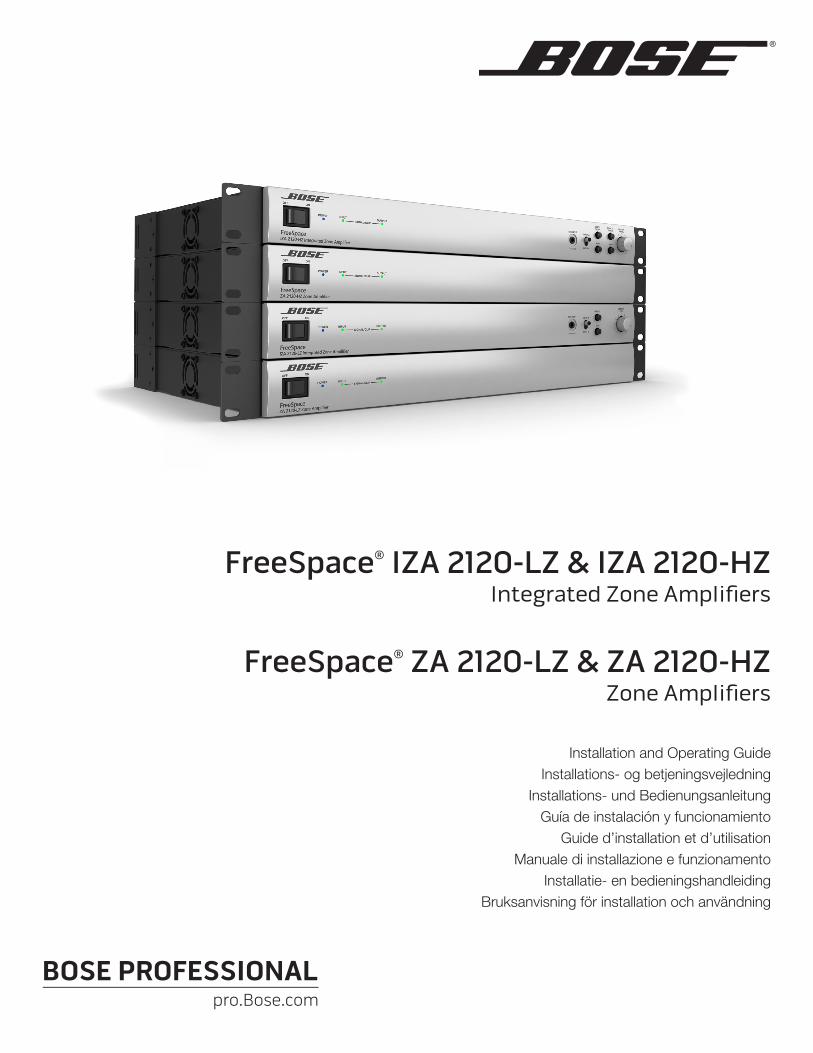
FreeSpace® IZA 2120-LZ & IZA 2120-HZIntegrated Zone Amplifiers
FreeSpace® ZA 2120-LZ & ZA 2120-HZZone Amplifiers
Installation and Operating GuideInstallations- og betjeningsvejledning
Installations- und BedienungsanleitungGuía de instalación y funcionamiento
Guide d’installation et d’utilisationManuale di installazione e funzionamento
Installatie- en bedieningshandleidingBruksanvisning för installation och användning

English Installation and Operation Page 3
Contents
IntroductionProduct overview .................................................................................................................................................................20
FreeSpace IZA 2120-LZ / IZA 2120-HZ integrated zone amplifier ..............................................................................20FreeSpace ZA 2120-LZ / ZA 2120-HZ zone amplifier .................................................................................................20
Included accessories ............................................................................................................................................................20Limited warranty ...................................................................................................................................................................20
Front and Rear PanelsFreeSpace® IZA 2120-LZ .....................................................................................................................................................21
IZA 2120-LZ front panel ...............................................................................................................................................21IZA 2120-LZ rear panel ................................................................................................................................................22
FreeSpace® IZA 2120-HZ .....................................................................................................................................................23IZA 2120-HZ front panel ..............................................................................................................................................23IZA 2120-HZ rear panel ...............................................................................................................................................24
FreeSpace® ZA 2120-LZ/HZ ................................................................................................................................................25ZA 2120-LZ/HZ front panel ..........................................................................................................................................25ZA 2120-LZ/HZ rear panel ...........................................................................................................................................25
Installation and PlacementImportance of proper ventilation ..........................................................................................................................................26Removing rack-mount ears ..................................................................................................................................................26Placing on a flat surface .......................................................................................................................................................26Installing the feet on the amplifier ........................................................................................................................................27Stacking units ......................................................................................................................................................................27
Making ConnectionsConnecting an amplifier to a ControlSpace® engineered sound processor .......................................................................28Page input connections ........................................................................................................................................................28Remote control connections ................................................................................................................................................29
Remote volume and source selection control .............................................................................................................29IZA 2120-HZ remote configuration examples ..............................................................................................................29
Remote connections to zone amplifiers ...............................................................................................................................31Remote volume control ................................................................................................................................................31ZA 2120-HZ remote configuration examples ...............................................................................................................32Remote input functionality ...........................................................................................................................................32Mute with standard contact closure ............................................................................................................................33
Loudspeaker usage ..............................................................................................................................................................33
Expanding an IZA system with a ZA amplifierExpansion overview..............................................................................................................................................................34Connecting an IZA 2120-LZ/HZ amplifier to a ZA 2120-LZ/HZ amplifier ............................................................................34Line input connections .........................................................................................................................................................34Connecting an IZA 2120-LZ/HZ amplifier to multiple zone amplifiers .................................................................................35
Technical InformationTroubleshooting ..................................................................................................................................................................36AC current draw and thermal dissipation information ..........................................................................................................37IZA 2120-LZ specifications ..................................................................................................................................................38IZA 2120-HZ specifications ..................................................................................................................................................39ZA 2120-LZ specifications ...................................................................................................................................................40ZA 2120-HZ specifications ...................................................................................................................................................41
Block Diagrams
Additional Resources
Important Safety Instructions pro.Bose.com
Page 4 Installation and Operation English
This product is intended for installation by professional installers only! This document is intended to provide professional installers with basic installation and safety guidelines for Bose® FreeSpace® amplifiers in typical fixed-installation systems. Please read this document before attempting installation.
Warning: All Bose products must be used in accordance with local, state, federal and industry regulations. It is the installer’s responsibility to ensure installation of the amplifier is performed in accordance with all applicable codes, including local building codes and regulations. Consult the local authority having jurisdiction before installing this product.
Warning: To reduce the risk of fire or electrical shock, do not expose the product to rain or moisture.
Caution: Do not mount the chassis in locations where condensation may occur.
Warning: Do not expose this apparatus to dripping or splashing, and do not place objects filled with liquids such as vases, on or near the apparatus. As with any electronic products, use care not to spill liquids into any part of the system. Liquids can cause a failure and/or a fire hazard.
The lightning flash with arrowhead symbol, within an equilateral triangle, is intended to alert the user to the presence of uninsulated dangerous voltage within the system enclosure that may be of sufficient magnitude to constitute a risk of electrical shock. Do not touch the output terminals while amplifier power is ON. Make all connections with amplifier OFF.
The exclamation point within an equilateral triangle, as marked on the system, is intended to alert the user to the presence of important operating and maintenance instructions in this installation guide.
Caution: This product shall be connected to an AC mains socket outlet with a protective earthing (grounding) connection.
Caution: Do not place any naked flame sources, such as lighted candles, on or near the apparatus.
Caution: Make no modifications to the system or accessories. Unauthorized alterations may compromise safety, regulatory compliance, and system performance.
Warning: Contains small parts which may be a choking hazard. Not suitable for children under age 3.
Note: The product label is located on the bottom of the product.
Note: Where the mains plug or appliance coupler is used as the disconnect device, such disconnect device shall remain readily operable.
Note: The product must be used indoors. It is neither designed nor tested for use outdoors, in recreational vehicles, or on boats.
English Installation and Operation Page 5
pro.Bose.com Important Safety Instructions
1. Read these instructions.
2. Keep these instructions – for future reference.
3. Heed all warnings – on the product and in all product documentation.
4. Follow all instructions.
5. Do not use this apparatus near water.
6. Clean only with a dry cloth.
7. Do not block any ventilation openings. Install in accordance with the manufacturer’s instructions. To ensure reliable operation of the product and to protect it from overheating put the product in a position and location that will not interfere with its proper ventilation.
8. Do not install near any heat sources, such as radiators, heat registers, stoves, or other apparatus (including amplifiers) that produce heat.
9. Do not defeat the safety purpose of the polarized or grounding-type plug. A polarized plug has two blades with one wider than the other. A grounding-type plug has two blades and a third grounding prong. The wider blade or third prong is provided for your safety. If the provided plug does not fit in your outlet, consult an electrician for replacement of the obsolete outlet.
10. Protect the power cord from being walked on or pinched, particularly at plugs, convenience receptacles, and the point where they exit from the apparatus.
11. Only use attachments/accessories specified by the manufacturer.
12. Use only with the cart, stand, tripod, bracket, or table specified by the manufacturer or sold with the apparatus. When a cart is used, use caution when moving the cart/apparatus combination to avoid injury from tip-over.
13. Unplug this apparatus during lightning storms or when unused for long periods of time to prevent damage to this product.
14. Refer all servicing to qualified service personnel. Servicing is required when the apparatus has been damaged in any way such as power-supply cord or plug is damaged; liquid has been spilled or objects have fallen into the apparatus; the apparatus has been exposed to rain or moisture, does not operate normally, or has been dropped. Do not attempt to service this product yourself. Opening or removing covers may expose you to dangerous voltages or other hazards. Please call Bose to be referred to an authorized service center near you.
This product conforms to all applicable EU directive requirements. The complete Declaration of Conformity can be found at www.Bose.com/compliance.
This Product meets the immunity requirements for the E2 class EN55103-2 directive.
Initial turn on inrush current: IZA 2120-LZ and IZA 2120-HZ: 12.6 Amps (230V/50 Hz), 6.6 Amps (120V/60 Hz) ZA 2120-LZ and ZA2120-HZ: 12.6 Amps (230V/50 Hz), 7.8 Amps (120V/60 Hz)
Inrush current after 5 seconds AC mains interruption: IZA 2120-LZ and IZA 2120-HZ: 12.5 Amps (230V/50 Hz), 6.5 Amps (120V/60 Hz) ZA 2120-LZ and ZA2120-HZ: 12.3 Amps (230V/50 Hz), 7.7 Amps (120V/60 Hz)
Information About Products That Generate Electrical Noise (FCC Compliance Notice for US)
Note: This equipment has been tested and found to comply with the limits for a Class A digital device, pursuant to part 15 of the FCC Rules. These limits are designed to provide reasonable protection against harmful interference when the equipment is operated in a commercial environment. This equipment generates, uses, and can radiate radio frequency energy and, if not installed and used in accordance with the instruction manual, may cause harmful interference to radio communications. Operation of this equipment in a residential area is likely to cause harmful interference in which case the user will be required to correct the interference at one’s own expense.
This product complies with the Canadian ICES-003 Class A specifications.
CAN ICES-3(A)/NMB-3(A)
Side 6 Installation og betjening Dansk
Vigtige sikkerhedsoplysninger pro.Bose.com
Dette produkt er kun beregnet til at anvendes af professionelle installatører! Dette dokument har til formål at give professionelle installatører grundlæggende installations- og sikkerhedsretningslinjer for Bose® FreeSpace®-forstærkere i typiske systemer med fast installation. Læs venligst dette dokument, inden du forsøger at foretage en installation.
Advarsel: Alle Bose-produkter skal anvendes i overensstemmelse med lokale regler, statslige regler og brancheregler. Det er installatørens ansvar at sikre, at installationen af forstærkeren foretages i overensstemmelse med alle relevante regler, herunder regler og forskrifter for den lokale bygning. Kontakt de lokale myndigheder, inden du installerer dette produkt.
Advarsel: Produktet må ikke udsættes for regn eller fugtighed på grund af risikoen for brand eller elektrisk stød.
Forsigtig: Monter ikke chassiset på steder, hvor der kan blive dannet kondens.
Advarsel: Udsæt ikke dette apparat for dryp eller stænk, og placer ikke genstande, der er fyldt med væske, på eller nær ved apparatet. Som ved alle elektriske apparater skal du passe på ikke at spilde væske på nogen af systemdelene. Væsker kan forårsage fejl i systemet og/eller medføre fare for brand.
Symbolet med et lyn med pilespids i en ligesidet trekant skal gøre brugeren opmærksom på tilstedeværelsen af en uisoleret farlig spænding i det lukkede system, der kan være tilstrækkelig kraftig til at give elektrisk stød. Rør ikke ved udgangsklemmerne, mens forstærkeren er tændt. Foretag alle tilslutninger, mens forstærkeren er slukket.
En ligebenet trekant med et udråbstegn, som markeret på systemet, skal henlede brugerens opmærksomhed på vigtige betjenings- og vedligeholdelsesinstruktioner i denne installationsvejledning.
Forsigtig: Dette produkt skal tilsluttes en stikkontakt med en beskyttende jordforbindelse.
Forsigtig: Placer ikke nogen form for åben ild (f.eks. stearinlys) på eller tæt ved apparatet.
Forsigtig: Undlad at foretage ændringer i systemet eller tilbehøret. Uautoriserede ændringer kan sætte sikkerheden, overholdelse af lovbestemmelser samt systemets ydeevne over styr.
Advarsel: Indeholder små dele, som kan udgøre en kvælningsfare. Egner sig ikke til børn under 3 år.
Bemærk: Produktmærkaten er placeret i bunden af produktet.
Bemærk: Hvis netstikket eller apparatets tænd/sluk-knap anvendes som afbryder, skal denne afbryder være let at komme til.
Bemærk: Produktet skal anvendes inden døre. Det er hverken designet eller testet til udendørs brug i fritidskøretøjer eller i lystbåde.
Dansk Installation og betjening Side 7
pro.Bose.com Vigtige sikkerhedsoplysninger
1. Læs disse instruktioner.
2. Gem disse instruktioner – til senere brug.
3. Følg alle advarsler – på produktet og i al produktdokumentation.
4. Følg alle instruktioner.
5. Anvend ikke dette apparat i nærheden af vand.
6. Rengør kun med en tør klud.
7. Undgå at blokere ventilationsåbningerne. Installer i overensstemmelse med producentens instruktioner. For at sikre pålidelig funktion og beskytte mod overophedning skal produktet anbringes i en position og på et sted, der ikke hindrer korrekt ventilation.
8. Installer ikke produktet i nærheden af varmekilder som f.eks. radiatorer, varmeovne, komfurer eller andre apparater (herunder forstærkere), der producerer varme.
9. Omgå ikke sikkerheden ved brug af et ikke-jordforbundet stik. Et polariseret stik har to stikben, hvor det ene er bredere end det andet. Et jordforbundet stik har to ben og et tredje jordben. Det brede ben eller tredje ben er der for din sikkerhed. Hvis det medfølgende stik ikke passer i stikkontakten, skal du kontakte en elektriker for at få stikkontakten udskiftet.
10. Beskyt netledningen mod at blive trådt på eller klemt, især ved stikkene, stikkontakter og på det sted, hvor den kommer ud af apparatet.
11. Brug kun tilslutningsudstyr/tilbehør, der er angivet af producenten.
12. Brug kun apparatet sammen med en vogn, et stativ, et beslag eller et bord, der er angivet af producenten eller solgt sammen med apparatet. Når der anvendes en vogn, skal der udvises forsigtighed ved kørsel med vogn/apparat, så det ikke vælter og forårsager kvæstelser.
13. Afbryd strømforsyningen til apparatet under tordenvejr, eller når det ikke skal bruges i en længere periode, for at fo-rhindre skade på produktet.
14. Overlad al servicering til kvalificeret servicepersonale. Et serviceeftersyn er påkrævet, når apparatet på nogen måde er beskadiget – hvis f.eks. netledningen eller strømstikket er beskadiget; der er blevet spildt væske; der er kommet genstande ind i apparatet; hvis apparatet er blevet udsat for regn eller fugt, ikke virker normalt eller er blevet tabt – forsøg ikke at servicere dette produkt selv. Åbning eller fjernelse af dæksler kan udsætte dig for farlige spændinger eller andre risici. Kontakt Bose for at få oplysninger om det nærmeste servicecenter.
Dette produkt overholder alle EU-direktivkrav i henhold til gældende lov. Den fulde overensstemmelseserklæring finder du på www.Bose.com/compliance.
Dette produkt lever op til immunitetskravene for direktivet E2 klasse EN55103-2.
Initialt startstrømstød, når enheden tændes: IZA 2120-LZ and IZA 2120-HZ: 12.6 Amps (230V/50 Hz), 6.6 Amps (120V/60 Hz) ZA 2120-LZ and ZA2120-HZ: 12.6 Amps (230V/50 Hz), 7.8 Amps (120V/60 Hz)
Startstrømstød efter 5 sekunders afbrydelse af lysnetstrømmen: IZA 2120-LZ and IZA 2120-HZ: 12.5 Amps (230V/50 Hz), 6.5 Amps (120V/60 Hz) ZA 2120-LZ and ZA2120-HZ: 12.3 Amps (230V/50 Hz), 7.7 Amps (120V/60 Hz)
Oplysninger om produkter, der genererer elektrisk støj (meddelelse om FCC-overensstemmelse for USA)
Bemærk: Dette udstyr er blevet testet og overholder grænserne for en digital enhed i klasse A i henhold til del 15 af FCC-reglerne. Disse grænser er udviklet til at yde rimelig beskyttelse mod skadelig interferens, når udstyret anvendes i en professionel installation. Dette udstyr genererer, bruger og kan udstråle radiofrekvensenergi, og kan – hvis det ikke installeres og bruges i overensstemmelse med brugervejledningen – forårsage skadelig interferens i forbindelse med radiokommunikation. Brug af dette udstyr i en privat installation kan forårsage skadelig interferens, og i så fald må brugeren få udbedret interferensen for egen regning.
Dette produkt overholder de canadiske ICES-003 Klasse A-specifikationer.
CAN ICES-3(A)/NMB-3(A)
Seite 8 Installation und Bedienung Deutsch
Wichtige Sicherheitshinweise pro.Bose.com
Dieses Produkt darf nur von fachkundigen Monteuren installiert werden! Dieses Dokument soll fachkundi-gen Monteuren grundlegende Installations- und Sicherheitsrichtlinie für Bose® FreeSpace®-Verstärker in typischen Festinstallationssystemen bieten. Bitte lesen Sie dieses Dokument vor der Installation durch.
Warnung: Alle Bose-Produkte müssen gemäß den örtlichen und staatlichen Vorschriften sowie gemäß allen Branchenbestimmungen verwendet werden. Der Monteur ist dafür verantwortlich, sicherzustellen, dass die Installation des Verstärkers gemäß allen geltenden Vorschriften durchgeführt wird, einschließlich örtlicher Bauvorschriften und Bestimmungen. Wenden Sie sich vor der Installation dieses Produkts an die zuständige Abnahmebehörde.
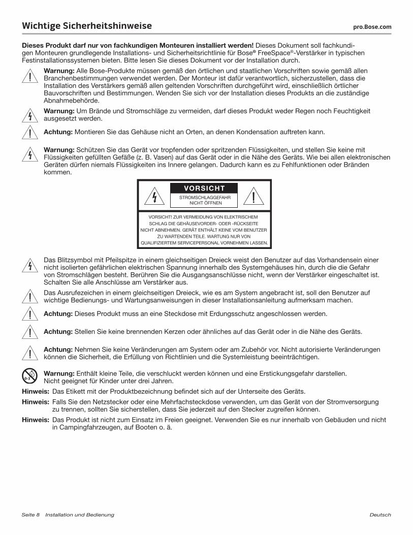
Warnung: Um Brände und Stromschläge zu vermeiden, darf dieses Produkt weder Regen noch Feuchtigkeit ausgesetzt werden.
Achtung: Montieren Sie das Gehäuse nicht an Orten, an denen Kondensation auftreten kann.
Warnung: Schützen Sie das Gerät vor tropfenden oder spritzenden Flüssigkeiten, und stellen Sie keine mit Flüssigkeiten gefüllten Gefäße (z. B. Vasen) auf das Gerät oder in die Nähe des Geräts. Wie bei allen elektronischen Geräten dürfen niemals Flüssigkeiten ins Innere gelangen. Dadurch kann es zu Fehlfunktionen oder Bränden kommen.
Das Blitzsymbol mit Pfeilspitze in einem gleichseitigen Dreieck weist den Benutzer auf das Vorhandensein einer nicht isolierten gefährlichen elektrischen Spannung innerhalb des Systemgehäuses hin, durch die die Gefahr von Stromschlägen besteht. Berühren Sie die Ausgangsanschlüsse nicht, wenn der Verstärker eingeschaltet ist. Schalten Sie alle Anschlüsse am Verstärker aus.
Das Ausrufezeichen in einem gleichseitigen Dreieck, wie es am System angebracht ist, soll den Benutzer auf wichtige Bedienungs- und Wartungsanweisungen in dieser Installationsanleitung aufmerksam machen.
Achtung: Dieses Produkt muss an eine Steckdose mit Erdungsschutz angeschlossen werden.
Achtung: Stellen Sie keine brennenden Kerzen oder ähnliches auf das Gerät oder in die Nähe des Geräts.
Achtung: Nehmen Sie keine Veränderungen am System oder am Zubehör vor. Nicht autorisierte Veränderungen können die Sicherheit, die Erfüllung von Richtlinien und die Systemleistung beeinträchtigen.
Warnung: Enthält kleine Teile, die verschluckt werden können und eine Erstickungsgefahr darstellen. Nicht geeignet für Kinder unter drei Jahren.
Hinweis: Das Etikett mit der Produktbezeichnung befindet sich auf der Unterseite des Geräts.
Hinweis: Falls Sie den Netzstecker oder eine Mehrfachsteckdose verwenden, um das Gerät von der Stromversorgung zu trennen, sollten Sie sicherstellen, dass Sie jederzeit auf den Stecker zugreifen können.
Hinweis: Das Produkt ist nicht zum Einsatz im Freien geeignet. Verwenden Sie es nur innerhalb von Gebäuden und nicht in Campingfahrzeugen, auf Booten o. ä.
Deutsch Installation und Bedienung Seite 9
pro.Bose.com Wichtige Sicherheitshinweise
1. Lesen Sie die folgenden Anweisungen.2. Bewahren Sie diese Anweisungen auf – zum späteren Nachschlagen.3. Beachten Sie alle Warnhinweise – am Produkt und in der gesamten Produktdokumentation.4. Befolgen Sie alle Anweisungen.5. Verwenden Sie dieses Gerät nicht in der Nähe von Wasser.6. Reinigen Sie das Gerät nur mit einem sauberen, trockenen Tuch.7. Achten Sie darauf, dass die Lüftungsöffnungen nicht blockiert sind. Stellen Sie das Gerät nur in Übereinstimmung mit
den Herstelleranweisungen auf – Stellen Sie es nur an einem Ort auf, an dem eine gute Ventilation gewährleistet ist, um den zuverlässigen Betrieb des Geräts sicherzustellen und es gegen Überhitzung zu schützen.
8. Stellen Sie das Gerät nicht in der Nähe von Wärmequellen auf, wie Heizkörper, Wärmespeicher, Öfen oder andere Geräten (auch Verstärker), die Wärme erzeugen.
9. Beeinträchtigen Sie in keiner Weise die Schutzfunktion des Schutzkontaktsteckers. Ein gepolter Stecker hat zwei Stromkontakte, von denen einer breiter als der andere ist. Ein Schutzkontaktstecker hat zwei Stromkontakte und einen dritten Erdungskontakt. Der dritte Kontakt dient der Sicherheit. Falls der mitgelieferte Stecker nicht in Ihre Steckdose passt, wenden Sie sich an einen qualifizierten Elektriker, um die Steckdose auszutauschen.
10. Verlegen Sie das Netzkabel so, dass es keine Stolpergefahr darstellt und nicht beschädigt werden kann – insbesondere im Bereich von Steckern und Steckdosen und dort, wo das Netzkabel aus dem Gerät herausgeführt wird.
11. Verwenden Sie nur Zubehör-/Anbauteile, die vom Hersteller zugelassen sind.12. Verwenden Sie für das Gerät nur Rollwagen, Ständer, Dreibeine, Halterungen oder Tische, die vom Hersteller
zugelassen sind oder zusammen mit dem Gerät verkauft werden. Falls Sie einen Rollwagen verwenden, dürfen Sie die Einheit Gerät/Rollwagen nur mit Vorsicht bewegen, damit Verletzungen beim möglichen Umkippen
ausgeschlossen sind.13. Ziehen Sie den Netzstecker des Geräts während eines Gewitters oder wenn Sie das Gerät längere Zeit nicht
benutzen – zur Vermeidung von Schäden am Produkt.14. Wenden Sie sich bei allen Reparatur- und Wartungsarbeiten nur an qualifiziertes Kundendienstpersonal.
Wartungsarbeiten sind in folgenden Fällen nötig: Bei jeglichen Beschädigungen wie z. B. des Netzkabels oder des Netzsteckers, wenn Flüssigkeiten oder Gegenstände in das Gehäuse gelangt sind, das Gerät Regen oder Feuchtigkeit ausgesetzt wurde, fallen gelassen wurde oder nicht ordnungsgemäß funktioniert – Versuchen Sie in solchen Fällen keinesfalls, das Gerät selbst zu reparieren. Öffnen oder entfernen Sie unter keinen Umständen die Gehäuseabdeckungen, da Sie andernfalls mit gefährlichenelektrischen Spannungen in Berührung kommen oder anderen Gefahren ausgesetzt sein könnten. Wenden Sie sich telefonisch an Bose, um die Anschrift eines autorisierten Kundendienstzentrums in Ihrer Nähe zu erfragen.
Dieses Produkt erfüllt alle vorgeschriebenen EU-Richtlinien. Die vollständige Konformitätserklärung ist einsehbar unter www.Bose.com/compliance.
Dieses Produkt erfüllt die Anforderungen an die Störfestigkeit der Klasse E2 der Richtlinie EN55103-2.Anfänglicher Einschaltstrom: IZA 2120-LZ and IZA 2120-HZ: 12.6 Amps (230V/50 Hz), 6.6 Amps (120V/60 Hz) ZA 2120-LZ and ZA2120-HZ: 12.6 Amps (230V/50 Hz), 7.8 Amps (120V/60 Hz)Einschaltstrom nach 5 Sekunden Unterbrechung des Netzanschlusses: IZA 2120-LZ and IZA 2120-HZ: 12.5 Amps (230V/50 Hz), 6.5 Amps (120V/60 Hz) ZA 2120-LZ and ZA2120-HZ: 12.3 Amps (230V/50 Hz), 7.7 Amps (120V/60 Hz)
Informationen über Produkte, die elektrisches Rauschen verursachen (Hinweis zur FCC-Einhaltung für die USA)Hinweis: Dieses Gerät wurde geprüft. Es stimmt mit den Regelungen für Geräte der Klasse A gemäß Teil 15 der
FCC-Vorschriften überein. Diese Grenzwerte sollen einen angemessenen Schutz gegen elektromagnetische Störungen beim Betrieb in gewerblicher Umgebung gewährleisten. Dieses Gerät erzeugt und verwendet Hochfrequenzstrahlung und kann sie auch aussenden. Daher verursacht das Gerät, wenn die Installation und Benutzung nicht in Übereinstimmung mit dieser Bedienungsanleitung erfolgt, möglicherweise Störungen des Funkverkehrs. Beim Betrieb dieses Geräts in Wohngebieten können erhebliche Störungen des Funkverkehrs verursacht werden. Eventuell daraus entstehende Kosten trägt allein der Benutzer des Geräts.
Dieses Produkt erfüllt die kanadische Richtlinie ICES-003, Klasse A. CAN ICES-3(A)/NMB-3(A)
Página 10 Instalación y funcionamiento Español
Instrucciones de seguridad importante pro.Bose.com
Solo un instalador profesional deberá montar este producto. Este documento está pensado para ofrecer a los instaladores profesionales instrucciones básicas de instalación y seguridad relacionadas con los amplificadores Bose® FreeSpace® en sistemas típicos de instalaciones fijas. Lea este documento antes de intentar la instalación.
Advertencia: todos los productos Bose se deben utilizar según lo estipulado en las normativas industriales locales, regionales y nacionales. Será responsabilidad del instalador garantizar que la instalación del amplificador se lleva a cabo según lo dispuesto en los códigos correspondientes, incluidos los códigos de construcción locales y las normativas. Consulte a las autoridades locales pertinentes antes de instalar este producto.
Advertencia: para reducir el riesgo de incendio o descarga eléctrica, no exponga el producto a lluvia o humedad.
Precaución: no monte el chasis en lugares donde pueda producirse condensación.
Advertencia: no exponga este aparato a salpicaduras o goteo. No coloque objetos que contengan líquidos, por ejemplo, jarrones, encima o cerca del aparato. Al igual que con cualquier producto electrónico, evite que se derramen líquidos en los componentes del sistema, ya que pueden provocar averías o riesgo de incendio.
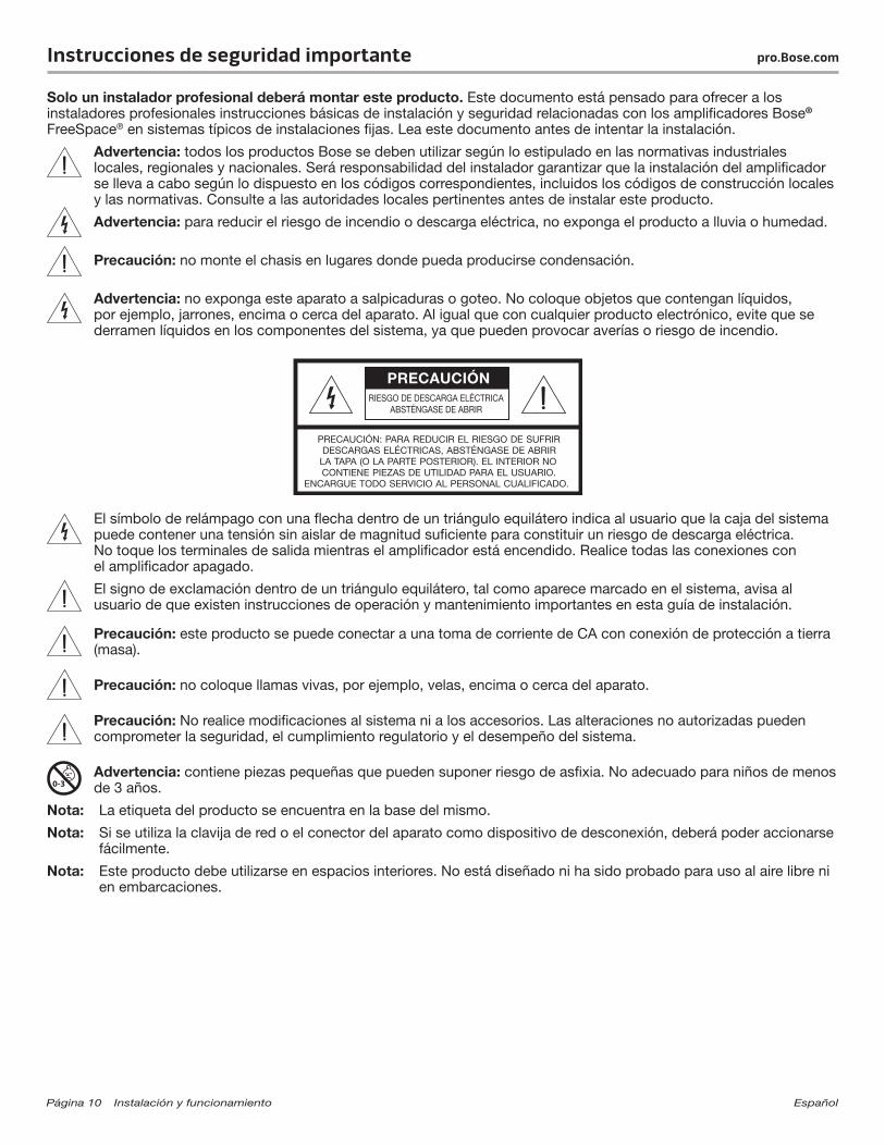
El símbolo de relámpago con una flecha dentro de un triángulo equilátero indica al usuario que la caja del sistema puede contener una tensión sin aislar de magnitud suficiente para constituir un riesgo de descarga eléctrica. No toque los terminales de salida mientras el amplificador está encendido. Realice todas las conexiones con el amplificador apagado.
El signo de exclamación dentro de un triángulo equilátero, tal como aparece marcado en el sistema, avisa al usuario de que existen instrucciones de operación y mantenimiento importantes en esta guía de instalación.
Precaución: este producto se puede conectar a una toma de corriente de CA con conexión de protección a tierra (masa).
Precaución: no coloque llamas vivas, por ejemplo, velas, encima o cerca del aparato.
Precaución: No realice modificaciones al sistema ni a los accesorios. Las alteraciones no autorizadas pueden comprometer la seguridad, el cumplimiento regulatorio y el desempeño del sistema.
Advertencia: contiene piezas pequeñas que pueden suponer riesgo de asfixia. No adecuado para niños de menos de 3 años.
Nota: La etiqueta del producto se encuentra en la base del mismo.
Nota: Si se utiliza la clavija de red o el conector del aparato como dispositivo de desconexión, deberá poder accionarse fácilmente.
Nota: Este producto debe utilizarse en espacios interiores. No está diseñado ni ha sido probado para uso al aire libre ni en embarcaciones.
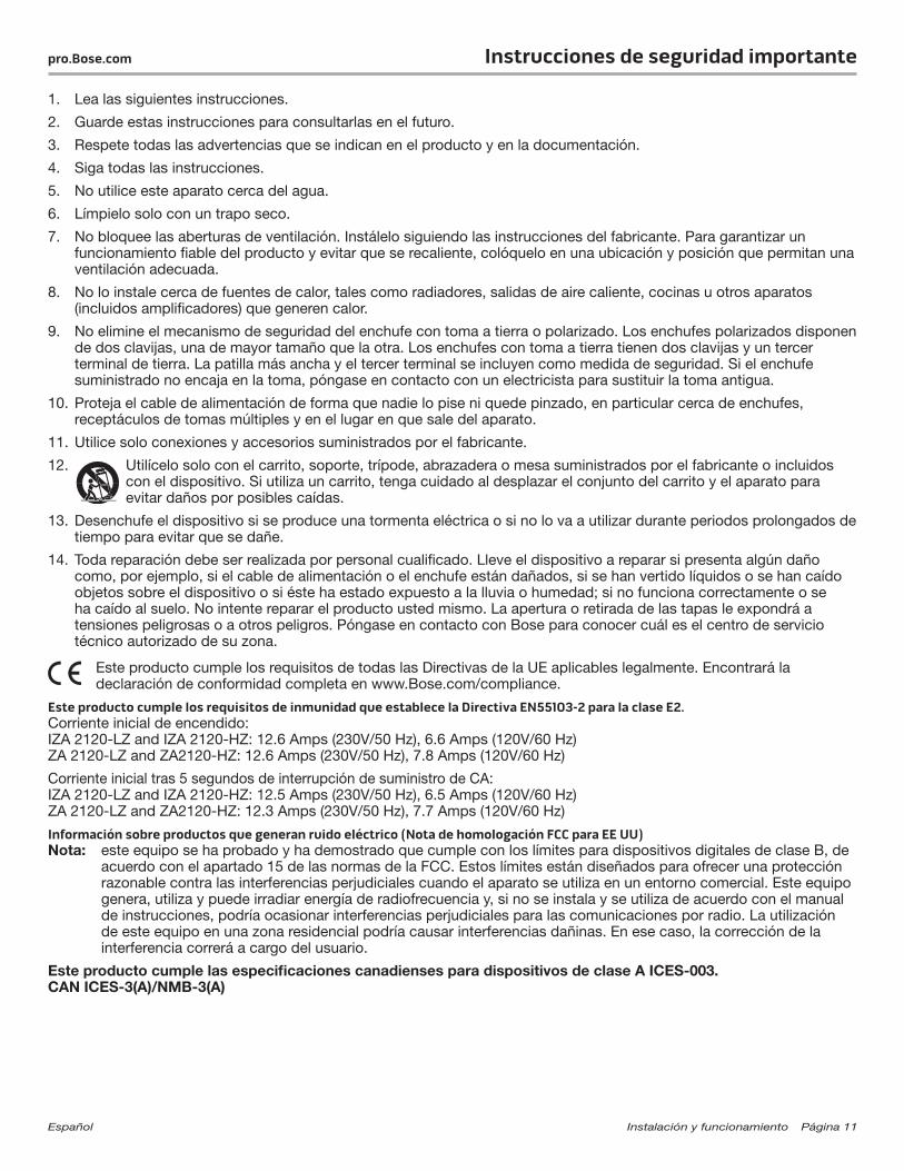
Español Instalación y funcionamiento Página 11
pro.Bose.com Instrucciones de seguridad importante
1. Lea las siguientes instrucciones.
2. Guarde estas instrucciones para consultarlas en el futuro.
3. Respete todas las advertencias que se indican en el producto y en la documentación.
4. Siga todas las instrucciones.
5. No utilice este aparato cerca del agua.
6. Límpielo solo con un trapo seco.
7. No bloquee las aberturas de ventilación. Instálelo siguiendo las instrucciones del fabricante. Para garantizar un funcionamiento fiable del producto y evitar que se recaliente, colóquelo en una ubicación y posición que permitan una ventilación adecuada.
8. No lo instale cerca de fuentes de calor, tales como radiadores, salidas de aire caliente, cocinas u otros aparatos (incluidos amplificadores) que generen calor.
9. No elimine el mecanismo de seguridad del enchufe con toma a tierra o polarizado. Los enchufes polarizados disponen de dos clavijas, una de mayor tamaño que la otra. Los enchufes con toma a tierra tienen dos clavijas y un tercer terminal de tierra. La patilla más ancha y el tercer terminal se incluyen como medida de seguridad. Si el enchufe suministrado no encaja en la toma, póngase en contacto con un electricista para sustituir la toma antigua.
10. Proteja el cable de alimentación de forma que nadie lo pise ni quede pinzado, en particular cerca de enchufes, receptáculos de tomas múltiples y en el lugar en que sale del aparato.
11. Utilice solo conexiones y accesorios suministrados por el fabricante.
12. Utilícelo solo con el carrito, soporte, trípode, abrazadera o mesa suministrados por el fabricante o incluidos con el dispositivo. Si utiliza un carrito, tenga cuidado al desplazar el conjunto del carrito y el aparato para evitar daños por posibles caídas.
13. Desenchufe el dispositivo si se produce una tormenta eléctrica o si no lo va a utilizar durante periodos prolongados de tiempo para evitar que se dañe.
14. Toda reparación debe ser realizada por personal cualificado. Lleve el dispositivo a reparar si presenta algún daño como, por ejemplo, si el cable de alimentación o el enchufe están dañados, si se han vertido líquidos o se han caído objetos sobre el dispositivo o si éste ha estado expuesto a la lluvia o humedad; si no funciona correctamente o se ha caído al suelo. No intente reparar el producto usted mismo. La apertura o retirada de las tapas le expondrá a tensiones peligrosas o a otros peligros. Póngase en contacto con Bose para conocer cuál es el centro de servicio técnico autorizado de su zona.
Este producto cumple los requisitos de todas las Directivas de la UE aplicables legalmente. Encontrará la declaración de conformidad completa en www.Bose.com/compliance.
Este producto cumple los requisitos de inmunidad que establece la Directiva EN55103-2 para la clase E2.Corriente inicial de encendido: IZA 2120-LZ and IZA 2120-HZ: 12.6 Amps (230V/50 Hz), 6.6 Amps (120V/60 Hz) ZA 2120-LZ and ZA2120-HZ: 12.6 Amps (230V/50 Hz), 7.8 Amps (120V/60 Hz)
Corriente inicial tras 5 segundos de interrupción de suministro de CA: IZA 2120-LZ and IZA 2120-HZ: 12.5 Amps (230V/50 Hz), 6.5 Amps (120V/60 Hz) ZA 2120-LZ and ZA2120-HZ: 12.3 Amps (230V/50 Hz), 7.7 Amps (120V/60 Hz)
Información sobre productos que generan ruido eléctrico (Nota de homologación FCC para EE UU)Nota: este equipo se ha probado y ha demostrado que cumple con los límites para dispositivos digitales de clase B, de
acuerdo con el apartado 15 de las normas de la FCC. Estos límites están diseñados para ofrecer una protección razonable contra las interferencias perjudiciales cuando el aparato se utiliza en un entorno comercial. Este equipo genera, utiliza y puede irradiar energía de radiofrecuencia y, si no se instala y se utiliza de acuerdo con el manual de instrucciones, podría ocasionar interferencias perjudiciales para las comunicaciones por radio. La utilización de este equipo en una zona residencial podría causar interferencias dañinas. En ese caso, la corrección de la interferencia correrá a cargo del usuario.
Este producto cumple las especificaciones canadienses para dispositivos de clase A ICES-003. CAN ICES-3(A)/NMB-3(A)
Page 12 Installation et utilisation Français
Instructions importantes relatives à la sécurité pro.Bose.com
L’installation de ce produit est réservée à un technicien professionnel ! Ce document à l’intention des installateurs professionnels contient les directives de pose et de sécurité relatives aux amplificateurs professionnels Bose® FreeSpace® en installation fixe. Lisez attentivement ce document avant l’installation.
Avertissement : Tous les produits Bose doivent être utilisés en respectant les réglementations locales et nationales. L’installateur est responsable du respect de tous les codes et règlements locaux et nationaux en vigueur applicables à l’installation de l’amplificateur. Consultez les autorités locales compétentes avant d’installer ce produit.
Avertissement : Pour limiter les risques d’incendie ou d’électrocution, n’exposez pas l’appareil à la pluie ou à l’humidité.
Attention : Ne montez pas le châssis dans des endroits où de la condensation peut se produire.
Avertissement : protégez l’appareil de tout risque de ruissellement ou d’éclaboussure. Ne placez pas d’objets contenant des liquides, tels que des vases, sur l’appareil. Comme avec tout appareil électronique, veillez à ne pas renverser de liquides sur une partie quelconque de l’appareil. Les liquides peuvent provoquer des pannes et/ou un risque d’incendie.
Le symbole représentant un éclair avec une flèche à l’intérieur d’un triangle équilatéral est utilisé pour prévenir l’utilisateur de la présence d’une tension électrique dangereuse non isolée à l’intérieur de l’appareil. Cette tension est d’un niveau suffisamment élevé pour représenter un risque d’électrocution. Ne touchez pas les bornes de sortie lorsque l’amplificateur est allumé. Mettez l’amplificateur hors tension avant de réaliser toute connexion.
Le symbole représentant un point d’exclamation à l’intérieur d’un triangle équilatéral, tel qu’il figure sur le système, signale à l’utilisateur la présence d’instructions importantes relatives au fonctionnement et à l’entretien de l’appareil dans cette notice d’installation.
Attention : Cet appareil doit être raccordé à une prise secteur dotée d’une mise à la terre.
Attention : Ne placez aucune source de flamme nue, comme une bougie allumée, sur ou près de l’appareil.
Attention : N’apportez aucune modification au système ou aux accessoires. Toute modification non autorisée peut compromettre votre sécurité, le respect des réglementations et les performances.
Attention : Certaines pièces présentent un risque de suffocation. Ne pas laisser à la portée des enfants de moins de 3 ans.
Remarque : L’étiquette d’identification du produit est située au-dessous de l’appareil.
Remarque : Lorsque la fiche d’alimentation ou la prise multiple est utilisée comme dispositif de débranchement de l’appareil, elle doit rester facilement accessible.
Remarque : Ce produit doit être utilisé à l’intérieur. Il n’a pas été conçu ni testé pour une utilisation en extérieur, dans des véhicules ou sur des bateaux.

Français Page sur l’installation et l’utilisation 13
pro.Bose.com Instructions importantes relatives à la sécurité
1. Veuillez lire ces instructions.
2. Conservez-les pour toute référence ultérieure.
3. Respectez tous les avertissements qui figurent sur le produit ou dans sa notice d’utilisation.
4. Suivez toutes les instructions.
5. N’utilisez pas cet appareil à proximité d’eau ou d’une source d’humidité.
6. Utilisez uniquement un chiffon sec pour le nettoyage.
7. Ne bloquez jamais les orifices d’aération. Suivez les instructions du fabricant pour l’installation. Pour garantir un fonctionnement fiable du produit et le protéger contre tout risque de surchauffe, installez-le à un emplacement et dans une position permettant d’assurer une ventilation correcte.
8. N’installez pas cet appareil à proximité d’une quelconque source de chaleur, telle qu’un radiateur, une arrivée d’air chaud, un four ou tout autre appareil (notamment des amplificateurs) produisant de la chaleur.
9. Veillez à profiter de la sécurité offerte par les fiches de type terre ou polarisées. Les fiches polarisées sont équipées de deux bornes de largeurs différentes. Les fiches de type terre sont équipées de deux bornes et d’un orifice pour la mise à la terre. Ces deux types de dispositifs ont pour but d’assurer votre sécurité. Si la prise fournie ne s’adapte pas à votre prise de courant, consultez un électricien pour qu’il remplace cette prise obsolète.
10. Protégez le cordon d’alimentation contre les risques de piétinement ou de pincement, notamment au niveau des fiches, des prises de courant et des branchements à l’appareil.
11. Utilisez uniquement les accessoires spécifiés par le fabricant.
12. Utilisez uniquement le chariot, le support, le trépied, l’équerre ou la table spécifié(e) par le fabricant ou vendu(e) avec l’appareil. Si vous utilisez un chariot, faites attention à ne pas faire basculer l’ensemble chariot/appareil pour éviter de vous blesser en cas de chute.
13. Débranchez cet appareil pendant les orages ou en cas d’inutilisation prolongée, afin d’éviter de l’endommager.
14. Confiez toute réparation à du personnel qualifié. Une réparation est nécessaire lorsque l’appareil a été endommagé de quelque façon que ce soit (endommagement du cordon d’alimentation ou de la fiche électrique, renversement d’un liquide ou de tout objet sur l’appareil, exposition de l’appareil à la pluie ou à l’humidité, mauvais fonctionnement, chute de l’appareil, etc.). Ne tentez pas de réparer ce produit vous-même. L’ouverture ou la dépose d’un couvercle risque de vous exposer à des tensions électriques ou autres dangers. Veuillez contacter Bose pour connaître les coordonnées du centre de réparation agréé le plus proche.
Ce produit est conforme à toutes les directives de la Communauté Européenne qui s’y appliquent. L’attestation complète de conformité est disponible à l’adresse www.Bose.com/compliance.
Ce produit répond aux critères d’immunité des directives EN55103-2 pour les appareils de classe E2.Courant d’appel à la mise sous tension : IZA 2120-LZ and IZA 2120-HZ: 12.6 Amps (230V/50 Hz), 6.6 Amps (120V/60 Hz) ZA 2120-LZ and ZA2120-HZ: 12.6 Amps (230V/50 Hz), 7.8 Amps (120V/60 Hz)
Courant d’appel après une interruption de 5 secondes de l’alimentation secteur : IZA 2120-LZ and IZA 2120-HZ: 12.5 Amps (230V/50 Hz), 6.5 Amps (120V/60 Hz) ZA 2120-LZ and ZA2120-HZ: 12.3 Amps (230V/50 Hz), 7.7 Amps (120V/60 Hz)
Informations sur les produits générateurs de bruit électrique (Notice de conformité FCC pour les USA)Remarque : ce matériel a fait l’objet de tests prouvant sa conformité aux limites imposées aux appareils numériques
de classe A, conformément à la partie 15 des réglementations de la FCC. Ces limites sont conçues pour offrir une protection raisonnable contre les interférences nuisibles lorsque l’appareil est utilisé en environnement commercial. Cet appareil génère, utilise et est susceptible d’émettre de l’énergie à certaines fréquences radio. À ce titre, s’il n’est pas installé ou utilisé conformément aux instructions, il est susceptible de perturber les communications radio. L’utilisation de cet équipement dans une zone résidentielle risque de provoquer des interférences nuisibles, auquel cas l’utilisateur devra remédier au problème à ses propres frais.
Ce produit est conforme aux spécifications de la réglementation ICES-003 pour la classe A du Canada. CAN ICES-3(A)/NMB-3(A)
Pagina 14 Installazione e funzionamento Italiano
Informazioni importanti sulla sicurezza pro.Bose.com
Questo prodotto deve essere installato unicamente da installatori professionisti. Questo documento ha lo scopo di fornire agli installatori professionisti le istruzioni di base per l’installazione e la sicurezza degli amplificatori Bose® FreeSpace® negli impianti convenzionali a installazione fissa. Leggere attentamente il documento prima di procedere all’installazione.
Avvertenza: Tutti i prodotti Bose devono essere utilizzati in conformità con gli standard locali, statali, federali e di settore. È responsabilità dell’installatore assicurare che l’installazione dell’amplificatore venga eseguita in conformità con le normative vigenti, compresi i regolamenti edilizi locali. Prima di installare il prodotto, chiedere informazioni all’autorità locale preposta.
Avvertenza: Per ridurre il rischio di incendio o scarica elettrica, non esporre il prodotto alla pioggia o all’umidità.
Attenzione: Non montare il telaio in posizioni dove potrebbe formarsi della condensa.
Avvertenza: Non esporre l’apparecchio a gocce o schizzi e non porre oggetti colmi di liquidi, quali vasi, sopra o accanto all’apparecchio. Come per qualsiasi prodotto elettronico, è importante che all’interno delle parti del sistema non penetrino liquidi in quanto potrebbero causare guasti e/o rischio di incendio.
Il simbolo del lampo con freccia racchiuso in un triangolo equilatero indica all’utilizzatore che all’interno dell’involucro è presente una tensione non isolata di entità tale da rappresentare un potenziale pericolo di scarica elettrica. Non toccare i terminali di uscita quando l’amplificatore è acceso. Disattivare prima tutti i collegamenti con l’amplificatore.
Il simbolo del punto esclamativo racchiuso all’interno di un triangolo equilatero, che appare sul sistema, rimanda l’utente alla lettura di istruzioni d’uso e manutenzione importanti contenute in questa guida.
Attenzione: Questo prodotto deve essere collegato a una presa di corrente alternata dotata di un impianto protettivo di messa a terra.
Attenzione: Non collocare sorgenti di fiamme libere (ad esempio candele accese) sull’apparecchio o nelle vicinanze dello stesso.
Attenzione: Non apportare modifiche al sistema o agli accessori in quanto le modifiche non autorizzate possono compromettere la sicurezza, la conformità alle norme e le prestazioni del sistema.
Avvertenza: Contiene pezzi di piccole dimensioni che possono rappresentare un pericolo di soffocamento. Non adatto per bambini di età inferiore ai 3 anni.
Nota: L’etichetta identificativa è situata sul fondo del prodotto.
Nota: La spina dell’alimentazione o dell’accoppiatore deve essere raggiungibile facilmente e rapidamente se è utilizzata come dispositivo di spegnimento.
Nota: Il prodotto è destinato all’uso in ambienti interni. Non è stato progettato né collaudato per l’uso in ambienti esterni, camper o imbarcazioni.
Italiano Installazione e funzionamento Pagina 15
pro.Bose.com Informazioni importanti sulla sicurezza
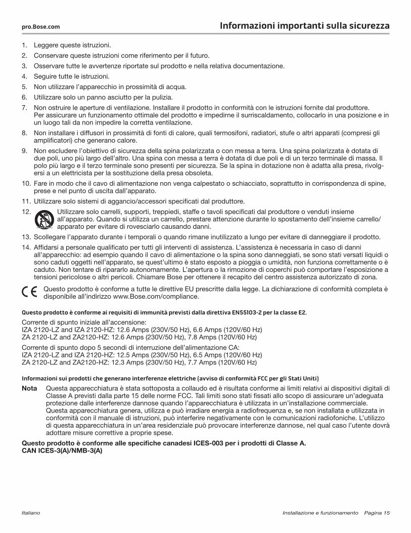
1. Leggere queste istruzioni.
2. Conservare queste istruzioni come riferimento per il futuro.
3. Osservare tutte le avvertenze riportate sul prodotto e nella relativa documentazione.
4. Seguire tutte le istruzioni.
5. Non utilizzare l’apparecchio in prossimità di acqua.
6. Utilizzare solo un panno asciutto per la pulizia.
7. Non ostruire le aperture di ventilazione. Installare il prodotto in conformità con le istruzioni fornite dal produttore. Per assicurare un funzionamento ottimale del prodotto e impedirne il surriscaldamento, collocarlo in una posizione e in un luogo tali da non impedire la corretta ventilazione.
8. Non installare i diffusori in prossimità di fonti di calore, quali termosifoni, radiatori, stufe o altri apparati (compresi gli amplificatori) che generano calore.
9. Non escludere l’obiettivo di sicurezza della spina polarizzata o con messa a terra. Una spina polarizzata è dotata di due poli, uno più largo dell’altro. Una spina con messa a terra è dotata di due poli e di un terzo terminale di massa. Il polo più largo e il terzo terminale sono presenti per sicurezza. Se la spina in dotazione non è adatta alla presa, rivolg-ersi a un elettricista per la sostituzione della presa obsoleta.
10. Fare in modo che il cavo di alimentazione non venga calpestato o schiacciato, soprattutto in corrispondenza di spine, prese e nel punto di uscita dall’apparato.
11. Utilizzare solo sistemi di aggancio/accessori specificati dal produttore.
12. Utilizzare solo carrelli, supporti, treppiedi, staffe o tavoli specificati dal produttore o venduti insieme all’apparato. Quando si utilizza un carrello, prestare attenzione durante lo spostamento dell’insieme carrello/apparato per evitare di rovesciarlo causando danni.
13. Scollegare l’apparato durante i temporali o quando rimane inutilizzato a lungo per evitare di danneggiare il prodotto.
14. Affidarsi a personale qualificato per tutti gli interventi di assistenza. L’assistenza è necessaria in caso di danni all’apparecchio: ad esempio quando il cavo di alimentazione o la spina sono danneggiati, se sono stati versati liquidi o sono caduti oggetti nell’apparato, se quest’ultimo è stato esposto a pioggia o umidità, non funziona correttamente o è caduto. Non tentare di ripararlo autonomamente. L’apertura o la rimozione di coperchi può comportare l’esposizione a tensioni pericolose o altri pericoli. Chiamare Bose per ottenere il recapito del centro assistenza autorizzato di zona.
Questo prodotto è conforme a tutte le direttive EU prescritte dalla legge. La dichiarazione di conformità completa è disponibile all’indirizzo www.Bose.com/compliance.
Questo prodotto è conforme ai requisiti di immunità previsti dalla direttiva EN55103-2 per la classe E2.
Corrente di spunto iniziale all’accensione: IZA 2120-LZ and IZA 2120-HZ: 12.6 Amps (230V/50 Hz), 6.6 Amps (120V/60 Hz) ZA 2120-LZ and ZA2120-HZ: 12.6 Amps (230V/50 Hz), 7.8 Amps (120V/60 Hz)
Corrente di spunto dopo 5 secondi di interruzione dell’alimentazione CA: IZA 2120-LZ and IZA 2120-HZ: 12.5 Amps (230V/50 Hz), 6.5 Amps (120V/60 Hz) ZA 2120-LZ and ZA2120-HZ: 12.3 Amps (230V/50 Hz), 7.7 Amps (120V/60 Hz)
Informazioni sui prodotti che generano interferenze elettriche (avviso di conformità FCC per gli Stati Uniti)
Nota Questa apparecchiatura è stata sottoposta a collaudo ed è risultata conforme ai limiti relativi ai dispositivi digitali di Classe A previsti dalla parte 15 delle norme FCC. Tali limiti sono stati fissati allo scopo di assicurare un’adeguata protezione dalle interferenze dannose quando l’apparecchiatura è utilizzata in un’installazione commerciale. Questa apparecchiatura genera, utilizza e può irradiare energia a radiofrequenza e, se non installata e utilizzata in conformità con il manuale di istruzioni, può interferire negativamente con le comunicazioni radiofoniche. L’utilizzo di questa apparecchiatura in un’area residenziale può provocare interferenze dannose, nel qual caso l’utente dovrà adottare misure correttive a proprie spese.
Questo prodotto è conforme alle specifiche canadesi ICES-003 per i prodotti di Classe A. CAN ICES-3(A)/NMB-3(A)
Pagina 16 Installatie en bediening Nederlands
Belangrijke veiligheidsinstructies pro.Bose.com
Dit product is uitsluitend bestemd voor installatie door professionele installateurs! Dit document is bedoeld om basisrichtlijnen met betrekking tot de installatie en veiligheid te bieden voor professionele installateurs voor Bose® FreeSpace®-versterkers in standaardsystemen voor vaste installatie. Lees dit document door voordat u begint met de installatie.
Waarschuwing: Alle Bose-producten moeten worden gebruikt volgens de plaatselijke en landelijke voorschriften en industrienormen. Het is de verantwoordelijkheid van de installateur om ervoor te zorgen dat de installatie van de versterker wordt uitgevoerd volgens alle van toepassing zijnde voorschriften, inclusief plaatselijke bouwvoorschriften. Neem contact op met de juiste plaatselijke overheidsinstanties voordat u dit product installeert.
Waarschuwing: Om het risico van brand of elektrische schokken te verlagen, mag dit product niet worden blootgesteld aan regen of vocht.
Opgelet: Monteer het chassis niet op plaatsen waar condensatie kan optreden.
Waarschuwing: Dit apparaat mag niet worden blootgesteld aan druipende of spattende vloeistoffen, en voorwerpen gevuld met vloeistoffen, zoals vazen, mogen niet op of bij het apparaat worden geplaatst. Evenals bij andere elektronische producten dient u op te letten dat er geen vloeistof op enig deel van het systeem terechtkomt. Vloeistoffen kunnen leiden tot storing en/of brandgevaar.
Het symbool met bliksemschicht en pijl in een gelijkzijdige driehoek is bedoeld om de gebruiker te waarschuwen voor de aanwezigheid van gevaarlijke niet-geïsoleerde spanning in het systeem die hoog genoeg kan zijn om een risico van elektrische schokken te vormen. Raak de uitgangsklemmen niet aan wanneer de versterker aanstaat. Sluit alle aansluitingen op de versterker af.
Het uitroepteken in de driehoek dat is afgebeeld op het systeem maakt de gebruiker attent op belangrijke bedienings- en onderhoudsinstructies in deze installatiehandleiding.
Opgelet: Dit product moet worden aangesloten op een geaard stopcontact.
Opgelet: Plaats geen open vlammen, zoals brandende kaarsen, op of bij het apparaat.
Opgelet: Breng geen wijzigingen aan aan het systeem of de accessoires. Wijzigingen door onbevoegden kunnen de veiligheid, de naleving van voorschriften en de werking van het systeem in gevaar brengen.
Waarschuwing: Bevat kleine onderdelen die een verstikkingsgevaar kunnen vormen. Niet geschikt voor kinderen jonger dan 3 jaar.
Opmerking: Het productlabel bevindt zich aan de onderkant van het product.
Opmerking: Wanneer de netstekker of connector als stroomonderbreker wordt gebruikt, dient een dergelijke stroomonderbreker gemakkelijk te bedienen te zijn.
Opmerking: Het product is alleen bestemd voor gebruik binnenshuis. Het is niet ontworpen of getest voor gebruik buitenshuis, in recreatievoertuigen of op boten.
Nederlands Installatie- en bedieningspagina 17
pro.Bose.com Belangrijke veiligheidsinstructies
1. Lees deze instructies door.
2. Bewaar deze instructies voor toekomstig gebruik.
3. Neem alle waarschuwingen in acht, zowel waarschuwingen op het product als in de documentatie van het product.
4. Volg alle instructies.
5. Gebruik dit apparaat niet in de buurt van water.
6. Reinig het apparaat alleen met een droge doek.
7. De ventilatieopeningen niet blokkeren. Installeren volgens de instructies van de fabrikant. Om een betrouwbare werking van het product te waarborgen en dit te beschermen tegen oververhitting, dient u het in een positie en op een plaats te zetten waar de ventilatie niet wordt belemmerd.
8. Niet installeren in de buurt van warmtebronnen, zoals radiatoren, verwarmingsroosters, kachels of andere apparaten (waaronder versterkers) die warmte produceren.
9. Schakel de veiligheidsfunctie van de gepolariseerde of aardingsstekker niet uit. Een gepolariseerde stekker heeft twee contactpennen waarbij de ene breder is dan de andere. Een geaarde stekker heeft twee contactpennen en een derde voor de aarding. De brede contactpen of derde contactpen dient voor uw veiligheid. Als de stekker niet in het stopcontact past, dient u contact op te nemen met een elektricien om het verouderde stopcontact te vervangen.
10. Zorg dat er niet op het netsnoer wordt gestaan of gelopen en dat het niet wordt afgekneld, met name bij de stekkers en stopcontacten en het punt waar deze uit het apparaat komen.
11. Gebruik uitsluitend randapparatuur/accessoires die worden gespecificeerd door de fabrikant.
12. Uitsluitend gebruiken in combinatie met het door de fabrikant voorgeschreven verrijdbare plateau, statief, drievoetbeugel of tafel die bij het apparaat wordt verkocht. Als u een verrijdbaar plateau gebruikt, moet u het plateau en het apparaat voorzichtig verplaatsen om letsel als gevolg van omvallen te voorkomen.
13. Verwijder de stekker van dit apparaat uit het stopcontact tijdens onweer of wanneer het lange tijd niet wordt gebruikt, om schade aan het product te voorkomen.
14. Laat alle onderhoud over aan bevoegd onderhoudspersoneel. Reparatie is vereist als het apparaat beschadigd is, zoals bij beschadiging van het netsnoer of de stekker; als er vloeistof in het apparaat terechtgekomen is of voorwerpen op het apparaat zijn gevallen; als het apparaat is blootgesteld aan regen of vocht, niet normaal werkt of is gevallen. Probeer dit product niet zelf te repareren. Door afdekkingen te openen of te verwijderen kunt u worden blootgesteld aan gevaarlijke spanningen of andere gevaren. Bel Bose voor een erkend servicecentrum bij u in de buurt.
Dit product voldoet aan alle vereisten van de EU-richtlijnen, zoals wettelijk vereist. De volledige conformiteitsverklaring kunt u vinden op www.Bose.com/compliance.
Dit product voldoet aan de immuniteitseisen van de richtlijn EN55103-2 klasse E2.Inschakelstroomstoot: IZA 2120-LZ and IZA 2120-HZ: 12.6 Amps (230V/50 Hz), 6.6 Amps (120V/60 Hz) ZA 2120-LZ and ZA2120-HZ: 12.6 Amps (230V/50 Hz), 7.8 Amps (120V/60 Hz)
Inschakelstroom na 5 seconden stroomuitval: IZA 2120-LZ and IZA 2120-HZ: 12.5 Amps (230V/50 Hz), 6.5 Amps (120V/60 Hz) ZA 2120-LZ and ZA2120-HZ: 12.3 Amps (230V/50 Hz), 7.7 Amps (120V/60 Hz)
Informatie over producten die elektrische ruis genereren (FCC Compliance Notice voor de VS)Opmerking: Dit apparaat is getest waarbij is vastgesteld dat het voldoet aan de limieten voor een digitaal apparaat van
klasse A, volgens deel 15 van de FCC-voorschriften. Deze limieten zijn bedoeld om redelijke bescherming te bieden tegen schadelijke storing bij installatie in een handelsomgeving. Dit apparaat genereert en gebruikt radiofrequente energie en kan deze uitstralen en het kan, als het niet geïnstalleerd en gebruikt wordt volgens de instructies, schadelijke storing veroorzaken aan radiocommunicatie. Gebruik van dit apparaat in een woonwijk kan schadelijke storing veroorzaken. In dit geval is de gebruiker verplicht op eigen kosten de storing te verhelpen.
Dit product voldoet aan de specificaties van de Canadese ICES-003 klasse A. CAN ICES-3(A)/NMB-3(A)
Sidan 18 Installation och användning Svenska
Viktig säkerhetsanvisningar pro.Bose.com
Denna produkt ska endast installeras av välutbildade installatörer. Detta dokument är avsett för professionella installatörer som behöver enkla riktlinjer för installation och säkerhet för Bose® FreeSpace®-förstärkare i vanliga fasta systeminstallationer. Läs igenom dokumentet innan du påbörjar installationen.
Varning! Alla Bose-produkter måste användas enligt lokala lagar och bestämmelser. Det är installatörens ansvar att förstärkarinstallationen utförs enligt gällande lager och regler, inklusive lokala bestämmelser och förordningar i huset. Kontakta berörd lokal myndighet innan du installerar produkten.
Varning! Minska risken för brand eller elektriska stötar genom att inte utsätta produkten för regn eller fukt.
Varning! Montera inte chassit på platser där kondens kan förekomma.
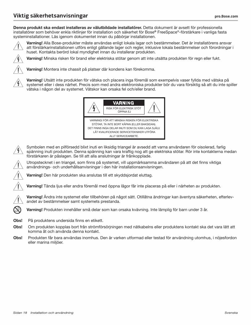
Varning! Utsätt inte produkten för vätska och placera inga föremål som exempelvis vaser fyllda med vätska på systemet eller i dess närhet. Precis som med andra elektroniska produkter bör du vara försiktig så att du inte spiller vätska i någon del av systemet. Vätskor kan orsaka fel och/eller brand.
Symbolen med en pilförsedd blixt inuti en liksidig triangel är avsedd att varna användaren för oisolerad, farlig spänning inuti produkten. Denna spänning kan vara kraftig nog att ge elektriska stötar. Rör inte kontakterna medan förstärkaren är påslagen. Se till att alla anslutningar är frånkopplade.
Utropstecknet i en triangel, som finns på systemet, vill uppmärksamma användaren på att det finns viktiga användnings- och underhållsanvisningar i den här installationsanvisningen.
Varning! Den här produkten ska anslutas till ett skyddsjordat eluttag.
Varning! Tända ljus eller andra föremål med öppna lågor får inte placeras på eller i närheten av produkten.
Varning! Ändra inte systemet eller tillbehören på något sätt. Otillåtna ändringar kan äventyra säkerheten, efterlev-andet av bestämmelser samt systemets prestanda.
Varning! Produkten innehåller små delar som kan orsaka kvävning. Inte lämplig för barn under 3 år.
Obs! På produktens undersida finns en etikett.
Obs! Om produkten kopplas bort från strömförsörjningen med nätkabelns eller produktens kontakt ska det vara lätt att komma åt och använda denna kontakt.
Obs! Produkten får bara användas inomhus. Den är varken utformad eller testad för användning utomhus, i nöjesfordon eller marina miljöer.
Svenska Installation och användning Sidan 19
pro.Bose.com Viktig säkerhetsanvisningar
1. Läs de här anvisningarna.
2. Spara anvisningarna för framtida referens.
3. Var uppmärksam på alla varningar, både på produkten och i all dokumentation.
4. Följ alla anvisningar.
5. Använd inte produkten i närheten av vatten.
6. Rengör endast med en torr trasa.
7. Blockera inte ventilationsöppningarna. Installera produkten i enlighet med tillverkarens anvisningar. För att produkten ska fungera tillförlitligt och skyddas från överhettning ska den placeras i ett sådant läge och på en sådan plats att tillräcklig luftväxling kan ske.
8. Installera inte produkten nära en värmekälla (som t.ex. radiator, värmespjäll och spisar) eller annan apparat (inklusive förstärkare) som avger värme.
9. Åsidosätt inte säkerhetsfunktionen i en polariserad eller jordad kontakt. En polariserad kontakt har två flata stift, det ena bredare än det andra. En jordad kontakt har två stift och ett tredje jordat stift. Det breda stiftet och jordstiftet finns där för att öka säkerheten. Om den medföljande kontakten inte passar i ditt eluttag ska du be en elektriker att byta ut det föråldrade uttaget.
10. Skydda elkabeln så att ingen trampar på den och så att den inte kommer i kläm. Detta är särskilt viktigt vid kontakterna, tillbehörsuttagen och den plats där elsladden kommer ut ur produkten.
11. Använd bara den utrustning/de tillbehör som rekommenderas av tillverkaren.
12. Använd endast produkten tillsammans med vagnen, stället, stativet, fästet eller bordet som rekommenderas av tillverkaren eller säljs tillsammans med produkten. Om en vagn används ska du vara försiktig när du flyttar vagnen med produkten på så att den inte välter och orsakar skada.
13. För att undvika skador på produkten ska du koppla bort produkten från eluttaget när åskan går eller om produkten inte ska användas under en längre period.
14. Låt utbildad servicepersonal utföra all service. Underhåll krävs när produkten skadats, t.ex. skada på kabel eller kontakt, vätska har spillts i produkten eller främmande föremål har hamnat i den; produkten har utsatts för regn eller fukt; produkten fungerar inte felfritt eller har tappats. Försök inte åtgärda felen själv. Om du öppnar eller tar bort några skydd riskerar du att utsättas för farlig elektrisk spänning eller andra faror. Ring till Bose så hjälper vi dig att hitta ett auktoriserat servicecenter nära dig.
Denna produkt uppfyller alla EU-direktiv som krävs enligt lag. En komplett försäkran om överensstämmelse finns på www.Bose.com/compliance.
Den här produkten uppfyller immunitetskraven enligt E2-klassen i direktivet EN55103-2.
Sätt initialt in inkommande strömstyrka: IZA 2120-LZ and IZA 2120-HZ: 12.6 Amps (230V/50 Hz), 6.6 Amps (120V/60 Hz) ZA 2120-LZ and ZA2120-HZ: 12.6 Amps (230V/50 Hz), 7.8 Amps (120V/60 Hz)
Inkommande strömstyrka efter fem sekunders strömavbrott: IZA 2120-LZ and IZA 2120-HZ: 12.5 Amps (230V/50 Hz), 6.5 Amps (120V/60 Hz) ZA 2120-LZ and ZA2120-HZ: 12.3 Amps (230V/50 Hz), 7.7 Amps (120V/60 Hz)
Information om produkter som genererar elektriskt brus (Meddelande angående FCC-överensstämmelse för USA)
Obs! Den här utrustningen har testats och befunnits överensstämma med gränsvärdena för digitala enheter av klass A, i enlighet med del 15 i FCC:s bestämmelser. Gränsvärdena är avsedda att ge rimligt skydd mot skadliga störningar när utrustningen används i en kommersiell miljö. Den här utrustningen genererar, använder och kan avge radiofrekvensenergi, och om utrustningen inte installeras och används i enlighet med anvisningarna kan den orsaka skadliga störningar i samband med radiokommunikation. Användning av denna utrustning i bostäder kan orsaka skadliga störningar som användaren själv måste åtgärda och bekosta.
Den här produkten överensstämmer med specifikationerna för klass A i kanadensiska ICES-003. CAN ICES-3(A)/NMB-3(A)

20 - English
pro.Bose.comIntroduction
Product overviewThis guide provides installation and operating information for FreeSpace® IZA 2120-LZ / IZA 2120-HZ integrated zone amplifiers and ZA 2120-LZ / ZA 2120-HZ zone amplifiers.
FreeSpace IZA 2120-LZ / IZA 2120-HZ integrated zone amplifierThe FreeSpace IZA 2120-LZ / IZA 2120-HZ integrated zone amplifier provides signal processing, routing, paging, zoning and amplification for a wide range of commercial applications such as retail stores, restaurants and bars, hospitality venues, conference rooms, schools and auxiliary zones.
The integrated zone amplifier offers a variety of input connections (mic/line/page), input gain and output level adjust-ments, and operational modes. Built-in Bose® FreeSpace FS3/HPF, DS 16, DS 40, DS 100, FS3B, and RoomMatch® Utility RMU105 loudspeaker EQ presets can be selected for loudspeaker optimization.
FreeSpace ZA 2120-LZ / ZA 2120-HZ zone amplifierThe FreeSpace ZA 2120-LZ / ZA 2120-HZ zone amplifier makes system expansion easy. Simply connect the auxiliary output of an IZA integrated zone amplifier to the input of a ZA zone amplifier. The two amplifiers will function together as one system sharing the same music, paging sources, master volume control and optional loudspeaker equalization.
ZA zone amplifiers are designed to expand sound systems that utilize front end signal processing from products such as the Bose FreeSpace IZA 2120-LZ, IZA 2120-HZ, IZA 250-LZ and IZA 190-HZ integrated zone amplifiers and Bose ControlSpace® engineered sound processors. The FreeSpace ZA 2120-LZ / ZA 2120-HZ zone amplifiers can also be used as stand-alone amplifiers from any balanced or unbalanced line-level source.
Included accessoriesEach carton includes one amplifier plus the items indicated in the following table:
IZA 2120-LZ IZA 2120-HZ ZA 2120-LZ ZA 2120-HZ
Feet with locking pins 4 4 4 4
5-pin Euroblock 2 2 1 1
4-pin Euroblock 1 black, 1 green 2 black, 1 green
2-pin Euroblock 1 black, 2 green 1 black, 2 green 2 black, 2 green 3 black, 2 green
RCA cable 1 1
AC power cord* 1 1 1 1
Owners Guide 1 1 1 1
*The appropriate power cord for your region is included.
AC power cord 2-pin Euroblock 4-pin Euroblocks3-pin Euroblock
Feet with pins (4)
5-pin Euroblock RCA cable
Limited warrantyYour product is covered by a limited warranty. Visit pro.Bose.com for warranty details.
English - 21
pro.Bose.com Front and Rear Panels
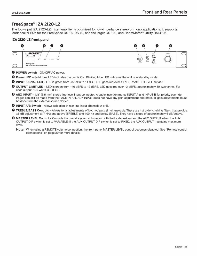
FreeSpace® IZA 2120-LZThe four-input IZA 2120-LZ mixer amplifier is optimized for low-impedance stereo or mono applications. It supports loudspeaker EQs for the FreeSpace DS 16, DS 40, and the larger DS 100, and RoomMatch® Utility RMU105.
IZA 2120-LZ front panel
POWER switch – ON/OFF AC power.
Power LED – Solid blue LED indicates the unit is ON. Blinking blue LED indicates the unit is in standby mode.
INPUT SIGNAL LED – LED is green from –37 dBu to 11 dBu, LED goes red over 11 dBu. MASTER LEVEL set at 5.
OUTPUT LIMIT LED – LED is green from –46 dBFS to –2 dBFS, LED goes red over –2 dBFS, approximately 80 W/channel. For each output, 120 watts is 0 dBFS.
AUX INPUT – 1/8" (3.5 mm) stereo line-level input connector. A cable insertion mutes INPUT A and INPUT B for priority override. Pages can still be made from the PAGE INPUT. AUX INPUT does not have any gain adjustment, therefore, all gain adjustments must be done from the external source device.
INPUT A/B Switch – Allows selection of rear line-input channels A or B.
TREBLE/BASS Controls – Allows tonal adjustments of both outputs simultaneously. These are 1st order shelving filters that provide ±6 dB adjustment at 7 kHz and above (TREBLE) and 100 Hz and below (BASS). They have a slope of approximately 6 dB/octave.
MASTER LEVEL Control – Controls the overall system volume for both the loudspeakers and the AUX OUTPUT when the AUX OUTPUT DIP switch is set to VARIABLE. If the AUX OUTPUT DIP switch is set to FIXED, the AUX OUTPUT maintains maximum level.
Note: When using a REMOTE volume connection, the front panel MASTER LEVEL control becomes disabled. See “Remote control connections” on page 29 for more details.
22 - English
Front and Rear Panels pro.Bose.com
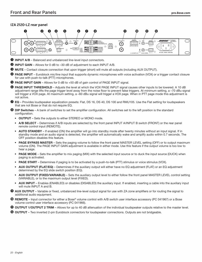
IZA 2120-LZ rear panel
AUX OUTPUTVARIABLEFIXED
INPUT A/B – Balanced and unbalanced line-level input connectors.
INPUT GAIN – Allows for 0 dB to –30 dB of adjustment to each INPUT A/B.
MUTE – Contact closure connection that upon trigger (short) will mute all outputs (including AUX OUTPUT).
PAGE INPUT – Euroblock mic/line input that supports dynamic microphones with voice activation (VOX) or a trigger contact closure for use with push-to-talk (PTT) microphones.
PAGE INPUT GAIN – Allows for 0 dB to +50 dB of gain control of PAGE INPUT signal.
PAGE INPUT THRESHOLD – Adjusts the level at which the VOX PAGE INPUT signal causes other inputs to be lowered. A 10 dB adjustment range lifts the page trigger level away from the noise floor to prevent false triggers. At minimum setting, a –70 dBu signal will trigger a VOX page. At maximum setting, a –60 dBu signal will trigger a VOX page. When in PTT page mode this adjustment is not active.
EQ – Provides loudspeaker equalization presets: Flat, DS 16, DS 40, DS 100 and RMU105. Use the Flat setting for loudspeakers that are not Bose or that do not require EQ.
DIP Switches – A bank of switches to set the amplifier configuration. All switches set to the left position is the standard configuration.
• OUTPUT – Sets the outputs to either STEREO or MONO mode.
• A/B SELECT – Determines if A/B inputs are selected by the front panel INPUT A/INPUT B switch (FRONT) or the rear panel remote control input (REMOTE).
• AUTO STANDBY – If enabled (ON) the amplifier will go into standby mode after twenty minutes without an input signal. If in standby mode and an audio signal is detected, the amplifier will automatically wake and amplify audio within 0.7 seconds. The OFF position disables this feature.
• PAGE BYPASS MASTER – Sets the paging volume to follow the front panel MASTER LEVEL setting (OFF) or to output maximum volume (ON). The PAGE INPUT GAIN adjustment is available in either mode. Use this feature if the output volume is too low to hear a page.
• PAGE MODE – Sets the amplifier to mix paging (MIX) with the selected input source or to duck the input source (DUCK) when paging is activated.
• PAGE START – Determines if paging is to be activated by a push-to-talk (PTT) stimulus or voice stimulus (VOX).
• AUX OUTPUT (FLAT/EQ) – Determines if the auxiliary output will either have no EQ adjustment (FLAT) or an EQ adjustment determined by the EQ slide switch position (EQ).
• AUX OUTPUT (FIXED/VARIABLE) – Sets the auxiliary output level to either follow the front panel MASTER LEVEL control setting (VARIABLE), or to the maximum output level (FIXED).
• AUX INPUT – Enables (ENABLED) or disables (DISABLED) the auxiliary input. If enabled, inserting a cable into the auxiliary input will mute INPUT A and B.
AUX OUTPUT – Variable or fixed, unbalanced line-level output signal for use with ZA zone amplifiers or for routing the signal to additional audio equipment.
REMOTE – Input connector for either a Bose® volume control with A/B switch user interface accessory (PC 041967) or a Bose volume control user interface accessory (PC 041966).
OUTPUT 1/OUTPUT 2 TRIM – Allows for up to 40 dB attenuation of the individual loudspeaker outputs relative to the master level.
OUTPUT – Two inverted 2-pin Euroblock connectors for loudspeaker connections. Outputs are not bridgeable.
English - 23
Front and Rear Panelspro.Bose.com
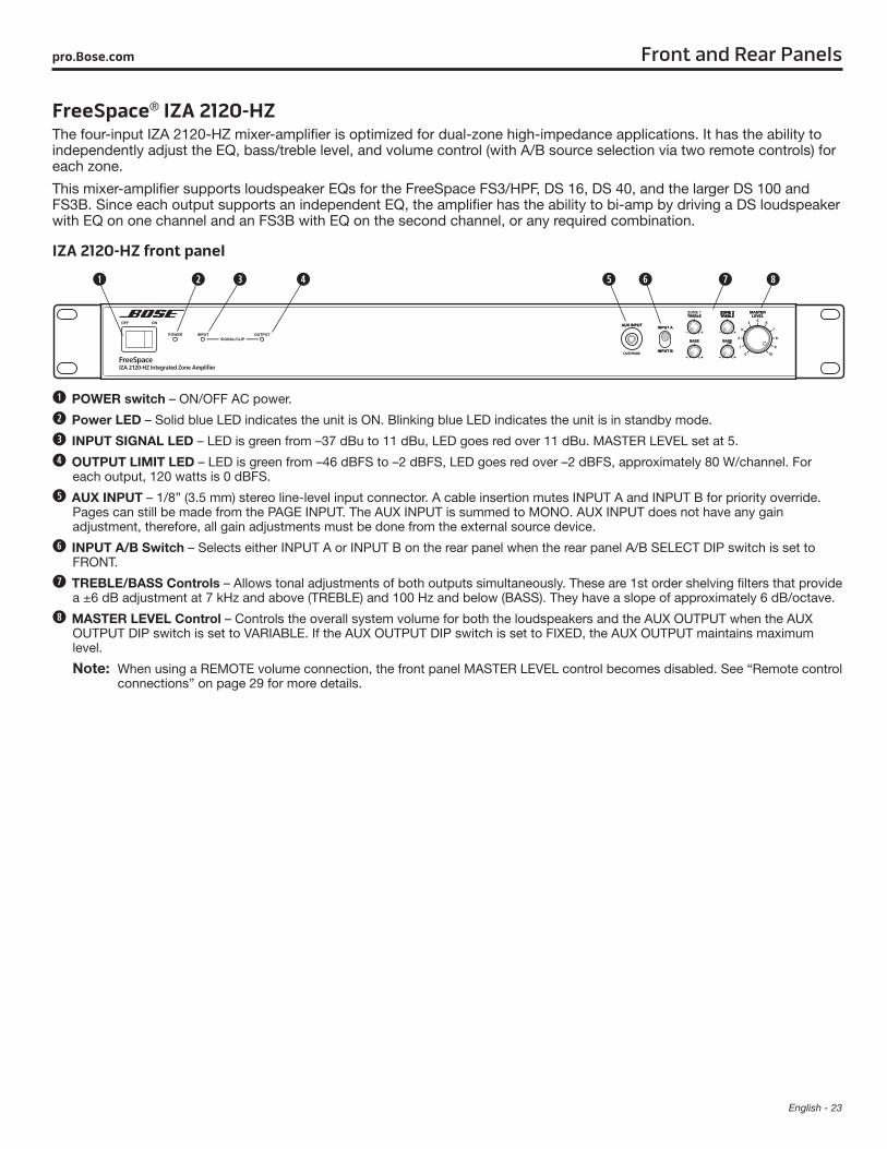
FreeSpace® IZA 2120-HZThe four-input IZA 2120-HZ mixer-amplifier is optimized for dual-zone high-impedance applications. It has the ability to independently adjust the EQ, bass/treble level, and volume control (with A/B source selection via two remote controls) for each zone.
This mixer-amplifier supports loudspeaker EQs for the FreeSpace FS3/HPF, DS 16, DS 40, and the larger DS 100 and FS3B. Since each output supports an independent EQ, the amplifier has the ability to bi-amp by driving a DS loudspeaker with EQ on one channel and an FS3B with EQ on the second channel, or any required combination.
IZA 2120-HZ front panel
POWER switch – ON/OFF AC power.
Power LED – Solid blue LED indicates the unit is ON. Blinking blue LED indicates the unit is in standby mode.
INPUT SIGNAL LED – LED is green from –37 dBu to 11 dBu, LED goes red over 11 dBu. MASTER LEVEL set at 5.
OUTPUT LIMIT LED – LED is green from –46 dBFS to –2 dBFS, LED goes red over –2 dBFS, approximately 80 W/channel. For each output, 120 watts is 0 dBFS.
AUX INPUT – 1/8” (3.5 mm) stereo line-level input connector. A cable insertion mutes INPUT A and INPUT B for priority override. Pages can still be made from the PAGE INPUT. The AUX INPUT is summed to MONO. AUX INPUT does not have any gain adjustment, therefore, all gain adjustments must be done from the external source device.
INPUT A/B Switch – Selects either INPUT A or INPUT B on the rear panel when the rear panel A/B SELECT DIP switch is set to FRONT.
TREBLE/BASS Controls – Allows tonal adjustments of both outputs simultaneously. These are 1st order shelving filters that provide a ±6 dB adjustment at 7 kHz and above (TREBLE) and 100 Hz and below (BASS). They have a slope of approximately 6 dB/octave.
MASTER LEVEL Control – Controls the overall system volume for both the loudspeakers and the AUX OUTPUT when the AUX OUTPUT DIP switch is set to VARIABLE. If the AUX OUTPUT DIP switch is set to FIXED, the AUX OUTPUT maintains maximum level.
Note: When using a REMOTE volume connection, the front panel MASTER LEVEL control becomes disabled. See “Remote control connections” on page 29 for more details.
24 - English
Front and Rear Panels pro.Bose.com
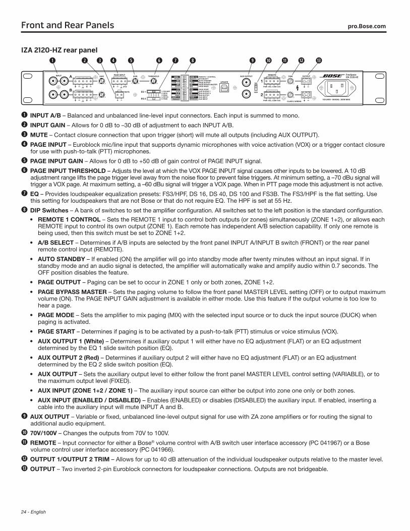
IZA 2120-HZ rear panel
INPUT A/B – Balanced and unbalanced line-level input connectors. Each input is summed to mono.
INPUT GAIN – Allows for 0 dB to –30 dB of adjustment to each INPUT A/B.
MUTE – Contact closure connection that upon trigger (short) will mute all outputs (including AUX OUTPUT).
PAGE INPUT – Euroblock mic/line input that supports dynamic microphones with voice activation (VOX) or a trigger contact closure for use with push-to-talk (PTT) microphones.
PAGE INPUT GAIN – Allows for 0 dB to +50 dB of gain control of PAGE INPUT signal.
PAGE INPUT THRESHOLD – Adjusts the level at which the VOX PAGE INPUT signal causes other inputs to be lowered. A 10 dB adjustment range lifts the page trigger level away from the noise floor to prevent false triggers. At minimum setting, a –70 dBu signal will trigger a VOX page. At maximum setting, a –60 dBu signal will trigger a VOX page. When in PTT page mode this adjustment is not active.
EQ – Provides loudspeaker equalization presets: FS3/HPF, DS 16, DS 40, DS 100 and FS3B. The FS3/HPF is the flat setting. Use this setting for loudspeakers that are not Bose or that do not require EQ. The HPF is set at 55 Hz.
DIP Switches – A bank of switches to set the amplifier configuration. All switches set to the left position is the standard configuration.
• REMOTE 1 CONTROL – Sets the REMOTE 1 input to control both outputs (or zones) simultaneously (ZONE 1+2), or allows each REMOTE input to control its own output (ZONE 1). Each remote has independent A/B selection capability. If only one remote is being used, then this switch must be set to ZONE 1+2.
• A/B SELECT – Determines if A/B inputs are selected by the front panel INPUT A/INPUT B switch (FRONT) or the rear panel remote control input (REMOTE).
• AUTO STANDBY – If enabled (ON) the amplifier will go into standby mode after twenty minutes without an input signal. If in standby mode and an audio signal is detected, the amplifier will automatically wake and amplify audio within 0.7 seconds. The OFF position disables the feature.
• PAGE OUTPUT – Paging can be set to occur in ZONE 1 only or both zones, ZONE 1+2.
• PAGE BYPASS MASTER – Sets the paging volume to follow the front panel MASTER LEVEL setting (OFF) or to output maximum volume (ON). The PAGE INPUT GAIN adjustment is available in either mode. Use this feature if the output volume is too low to hear a page.
• PAGE MODE – Sets the amplifier to mix paging (MIX) with the selected input source or to duck the input source (DUCK) when paging is activated.
• PAGE START – Determines if paging is to be activated by a push-to-talk (PTT) stimulus or voice stimulus (VOX).
• AUX OUTPUT 1 (White) – Determines if auxiliary output 1 will either have no EQ adjustment (FLAT) or an EQ adjustment determined by the EQ 1 slide switch position (EQ).
• AUX OUTPUT 2 (Red) – Determines if auxiliary output 2 will either have no EQ adjustment (FLAT) or an EQ adjustment determined by the EQ 2 slide switch position (EQ).
• AUX OUTPUT – Sets the auxiliary output level to either follow the front panel MASTER LEVEL control setting (VARIABLE), or to the maximum output level (FIXED).
• AUX INPUT (ZONE 1+2 / ZONE 1) – The auxiliary input source can either be output into zone one only or both zones.
• AUX INPUT (ENABLED / DISABLED) – Enables (ENABLED) or disables (DISABLED) the auxiliary input. If enabled, inserting a cable into the auxiliary input will mute INPUT A and B.
AUX OUTPUT – Variable or fixed, unbalanced line-level output signal for use with ZA zone amplifiers or for routing the signal to additional audio equipment.
70V/100V – Changes the outputs from 70V to 100V.
REMOTE – Input connector for either a Bose® volume control with A/B switch user interface accessory (PC 041967) or a Bose volume control user interface accessory (PC 041966).
OUTPUT 1/OUTPUT 2 TRIM – Allows for up to 40 dB attenuation of the individual loudspeaker outputs relative to the master level.
OUTPUT – Two inverted 2-pin Euroblock connectors for loudspeaker connections. Outputs are not bridgeable.
English - 25
Front and Rear Panelspro.Bose.com
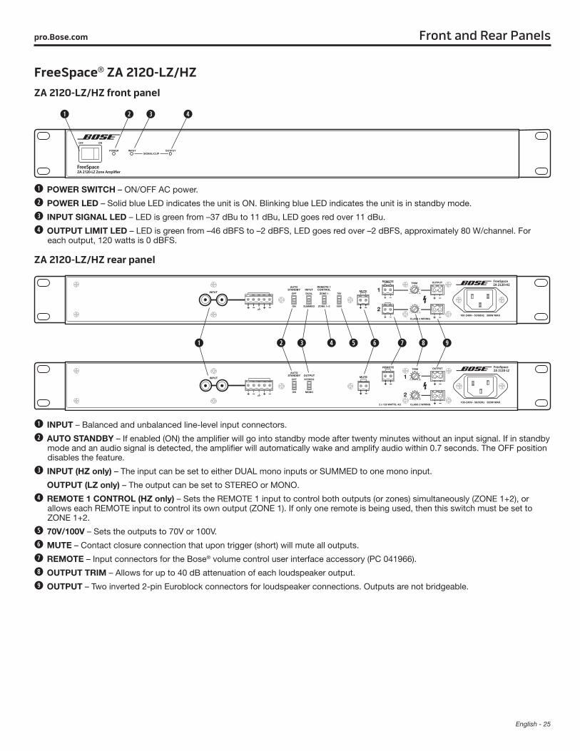
FreeSpace® ZA 2120-LZ/HZZA 2120-LZ/HZ front panel
POWER SWITCH – ON/OFF AC power.
POWER LED – Solid blue LED indicates the unit is ON. Blinking blue LED indicates the unit is in standby mode.
INPUT SIGNAL LED – LED is green from –37 dBu to 11 dBu, LED goes red over 11 dBu.
OUTPUT LIMIT LED – LED is green from –46 dBFS to –2 dBFS, LED goes red over –2 dBFS, approximately 80 W/channel. For each output, 120 watts is 0 dBFS.
ZA 2120-LZ/HZ rear panel
INPUT – Balanced and unbalanced line-level input connectors.
AUTO STANDBY – If enabled (ON) the amplifier will go into standby mode after twenty minutes without an input signal. If in standby mode and an audio signal is detected, the amplifier will automatically wake and amplify audio within 0.7 seconds. The OFF position disables the feature.
INPUT (HZ only) – The input can be set to either DUAL mono inputs or SUMMED to one mono input.
OUTPUT (LZ only) – The output can be set to STEREO or MONO.
REMOTE 1 CONTROL (HZ only) – Sets the REMOTE 1 input to control both outputs (or zones) simultaneously (ZONE 1+2), or allows each REMOTE input to control its own output (ZONE 1). If only one remote is being used, then this switch must be set to ZONE 1+2.
70V/100V – Sets the outputs to 70V or 100V.
MUTE – Contact closure connection that upon trigger (short) will mute all outputs.
REMOTE – Input connectors for the Bose® volume control user interface accessory (PC 041966).
OUTPUT TRIM – Allows for up to 40 dB attenuation of each loudspeaker output.
OUTPUT – Two inverted 2-pin Euroblock connectors for loudspeaker connections. Outputs are not bridgeable.
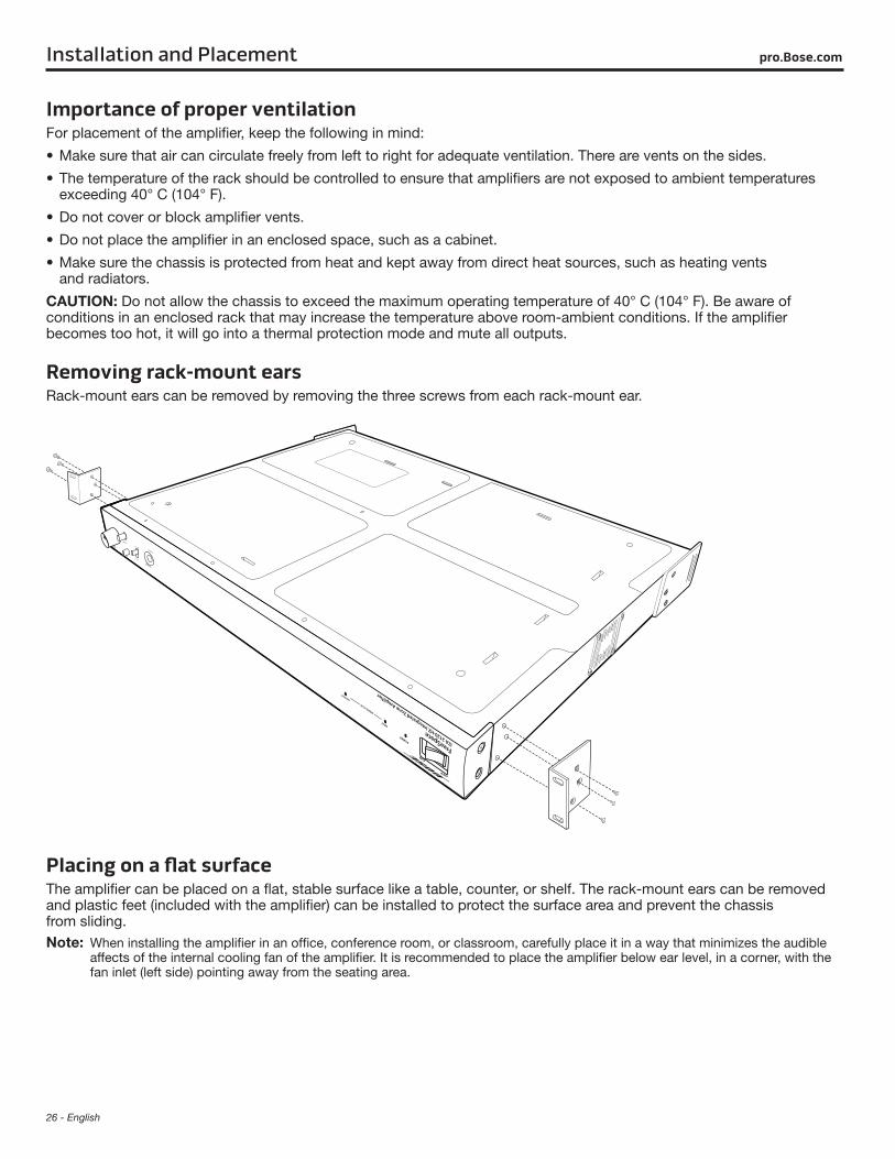
26 - English
pro.Bose.comInstallation and Placement
Importance of proper ventilationFor placement of the amplifier, keep the following in mind:
• Make sure that air can circulate freely from left to right for adequate ventilation. There are vents on the sides.
• The temperature of the rack should be controlled to ensure that amplifiers are not exposed to ambient temperatures exceeding 40° C (104° F).
• Do not cover or block amplifier vents.
• Do not place the amplifier in an enclosed space, such as a cabinet.
• Make sure the chassis is protected from heat and kept away from direct heat sources, such as heating vents and radiators.
CAUTION: Do not allow the chassis to exceed the maximum operating temperature of 40° C (104° F). Be aware of conditions in an enclosed rack that may increase the temperature above room-ambient conditions. If the amplifier becomes too hot, it will go into a thermal protection mode and mute all outputs.
Removing rack-mount earsRack-mount ears can be removed by removing the three screws from each rack-mount ear.
Placing on a flat surfaceThe amplifier can be placed on a flat, stable surface like a table, counter, or shelf. The rack-mount ears can be removed and plastic feet (included with the amplifier) can be installed to protect the surface area and prevent the chassis from sliding.Note: When installing the amplifier in an office, conference room, or classroom, carefully place it in a way that minimizes the audible
affects of the internal cooling fan of the amplifier. It is recommended to place the amplifier below ear level, in a corner, with the fan inlet (left side) pointing away from the seating area.
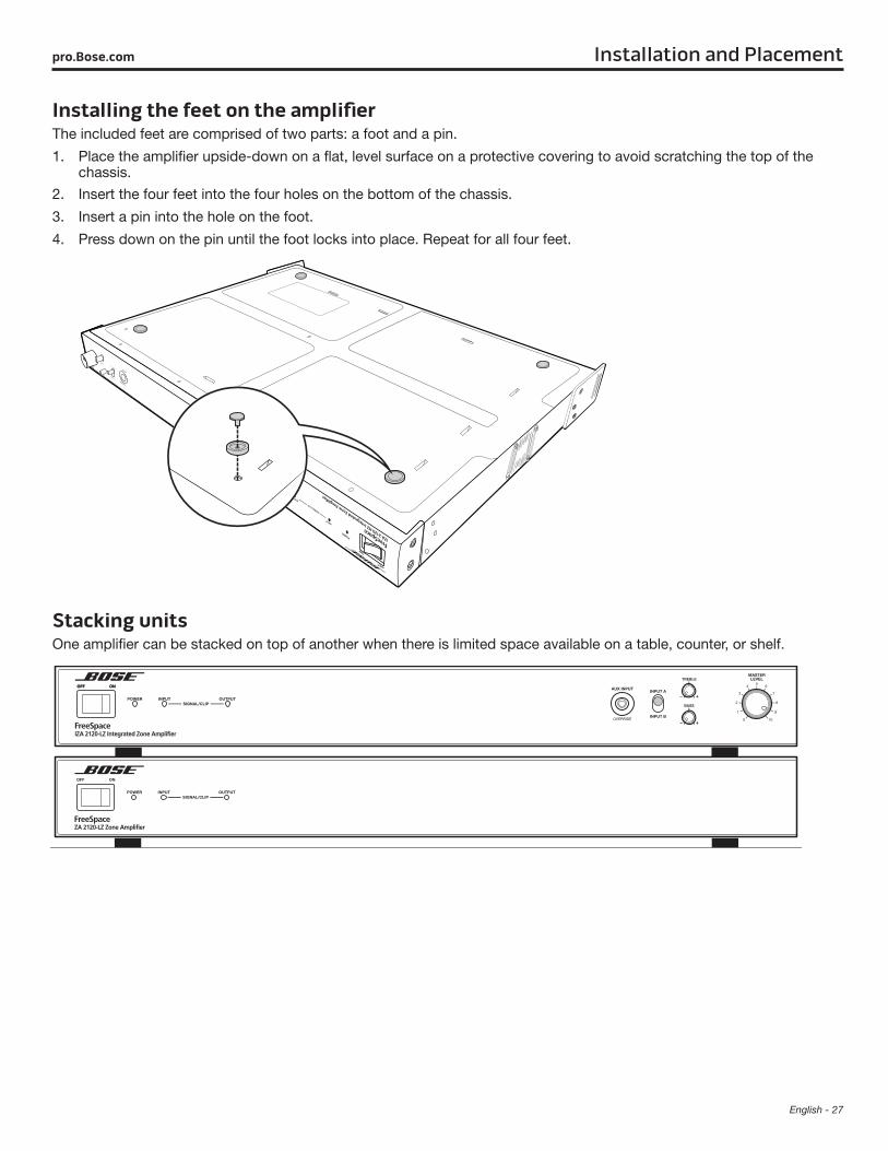
English - 27
Installation and Placementpro.Bose.com
Installing the feet on the amplifierThe included feet are comprised of two parts: a foot and a pin.
1. Place the amplifier upside-down on a flat, level surface on a protective covering to avoid scratching the top of the chassis.
2. Insert the four feet into the four holes on the bottom of the chassis.
3. Insert a pin into the hole on the foot.
4. Press down on the pin until the foot locks into place. Repeat for all four feet.
Stacking units One amplifier can be stacked on top of another when there is limited space available on a table, counter, or shelf.
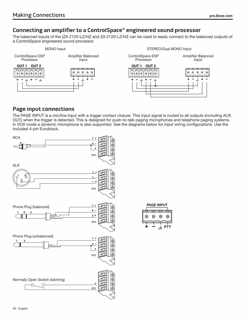
28 - English
pro.Bose.comMaking Connections
Connecting an amplifier to a ControlSpace® engineered sound processor The balanced inputs of the IZA 2120-LZ/HZ and ZA 2120-LZ/HZ can be used to easily connect to the balanced outputs of a ControlSpace engineered sound processor.
MONO Input STEREO/Dual MONO Input
ControlSpace ESP Processor
Amplifier Balanced Input
ControlSpace ESP Processor
Amplifier Balanced Input
Page input connectionsThe PAGE INPUT is a mic/line input with a trigger contact closure. This input signal is routed to all outputs (including AUX OUT) when the trigger is detected. This is designed for push-to-talk paging microphones and telephone paging systems. In VOX mode a dynamic microphone is also supported. See the diagrams below for input wiring configurations. Use the included 4-pin Euroblock.
Phone Plug (balanced)
Phone Plug (unbalanced)
Normally Open Switch (latching)
RCA
XLR
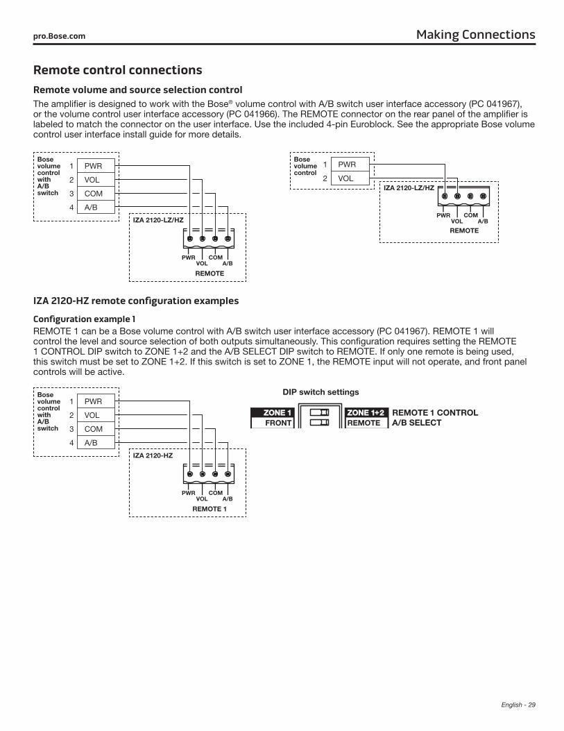
English - 29
Making Connectionspro.Bose.com
Remote control connectionsRemote volume and source selection controlThe amplifier is designed to work with the Bose® volume control with A/B switch user interface accessory (PC 041967), or the volume control user interface accessory (PC 041966). The REMOTE connector on the rear panel of the amplifier is labeled to match the connector on the user interface. Use the included 4-pin Euroblock. See the appropriate Bose volume control user interface install guide for more details.
1 PWR
2 VOL
3 COM
4 A/B
IZA 2120-LZ/HZ
Bose volume control with A/B switch
REMOTE
Bose volume control
1 PWR
2 VOLIZA 2120-LZ/HZ
REMOTE
IZA 2120-HZ remote configuration examples
Configuration example 1REMOTE 1 can be a Bose volume control with A/B switch user interface accessory (PC 041967). REMOTE 1 will control the level and source selection of both outputs simultaneously. This configuration requires setting the REMOTE 1 CONTROL DIP switch to ZONE 1+2 and the A/B SELECT DIP switch to REMOTE. If only one remote is being used, this switch must be set to ZONE 1+2. If this switch is set to ZONE 1, the REMOTE input will not operate, and front panel controls will be active.
1 PWR
2 VOL
3 COM
4 A/B
IZA 2120-HZ
Bose volume control with A/B switch
REMOTE 1
DIP switch settings
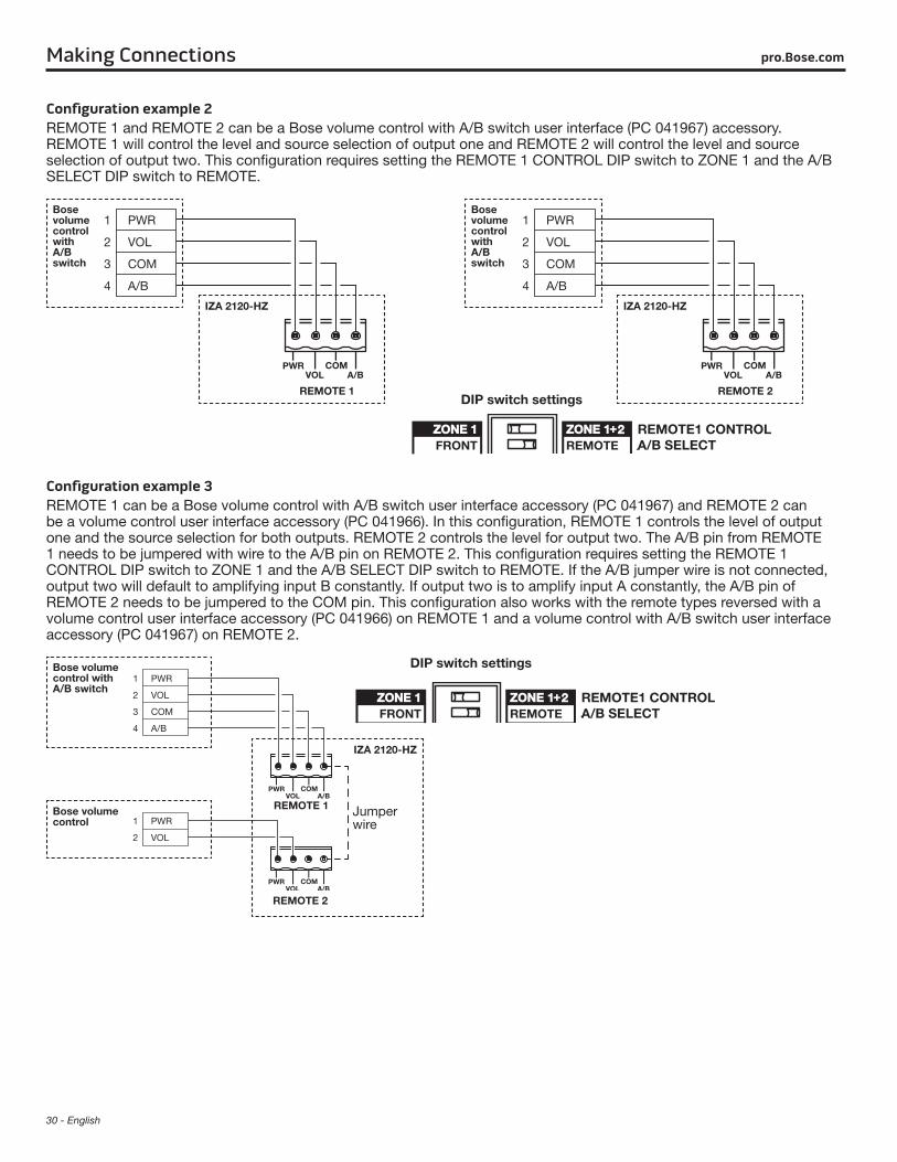
30 - English
Making Connections pro.Bose.com
Configuration example 2REMOTE 1 and REMOTE 2 can be a Bose volume control with A/B switch user interface (PC 041967) accessory. REMOTE 1 will control the level and source selection of output one and REMOTE 2 will control the level and source selection of output two. This configuration requires setting the REMOTE 1 CONTROL DIP switch to ZONE 1 and the A/B SELECT DIP switch to REMOTE.
1 PWR
2 VOL
3 COM
4 A/B
IZA 2120-HZ
Bose volume control with A/B switch
REMOTE 1DIP switch settings
1 PWR
2 VOL
3 COM
4 A/B
IZA 2120-HZ
Bose volume control with A/B switch
REMOTE 2
Configuration example 3REMOTE 1 can be a Bose volume control with A/B switch user interface accessory (PC 041967) and REMOTE 2 can be a volume control user interface accessory (PC 041966). In this configuration, REMOTE 1 controls the level of output one and the source selection for both outputs. REMOTE 2 controls the level for output two. The A/B pin from REMOTE 1 needs to be jumpered with wire to the A/B pin on REMOTE 2. This configuration requires setting the REMOTE 1 CONTROL DIP switch to ZONE 1 and the A/B SELECT DIP switch to REMOTE. If the A/B jumper wire is not connected, output two will default to amplifying input B constantly. If output two is to amplify input A constantly, the A/B pin of REMOTE 2 needs to be jumpered to the COM pin. This configuration also works with the remote types reversed with a volume control user interface accessory (PC 041966) on REMOTE 1 and a volume control with A/B switch user interface accessory (PC 041967) on REMOTE 2.
1 PWR
2 VOL
3 COM
4 A/B
1 PWR
2 VOL
Bose volume control with A/B switch
Bose volume control
IZA 2120-HZ
REMOTE 1
REMOTE 2
Jumper wire
DIP switch settings
English - 31
Making Connectionspro.Bose.com
Configuration example 4REMOTE 1 and REMOTE 2 can be a volume control user interface accessory (PC 041966). In this configuration, REMOTE 1 controls the level of output one and REMOTE 2 controls the level for output two. A/B source selection for both outputs is simultaneously controlled by the front panel switch. This configuration requires setting the REMOTE 1 CONTROL DIP switch to ZONE 1 and the A/B SELECT DIP switch to FRONT.
Bose volume control
1 PWR
2 VOLIZA 2120-HZ
REMOTE 1
Bose volume control
1 PWR
2 VOLIZA 2120-HZ
REMOTE 2
DIP switch settings
Configuration example 5REMOTE 1 can be a volume control user interface accessory (PC 041966). In this configuration, REMOTE 1 controls the level of both outputs simultaneously. A/B source selection for both outputs is simultaneously controlled by the front panel switch. This configuration requires setting the REMOTE 1 CONTROL DIP switch to ZONE 1+2 and the A/B SELECT DIP switch to FRONT.
Bose volume control
1 PWR
2 VOLIZA 2120-HZ
REMOTE 1
DIP switch settings
Remote connections to zone amplifiersRemote volume controlThe zone amplifiers are designed to work with the Bose® volume control user interface accessory (PC 041966). The REMOTE connector on the rear panel of the amplifier is labeled to match the connector on the user interface. Use the included 2-pin Euroblock. See the Bose volume control user interface accessory install guide for more details.
1 PWR
2 VOL
REMOTE 1
ZA 2120-LZ/HZ
Bose volume control
32 - English
Making Connections pro.Bose.com
ZA 2120-HZ remote configuration examples
Configuration example 1REMOTE 1 can be a Bose® volume control user interface accessory (PC 041966). REMOTE 1 will control the level of both outputs simultaneously. This configuration requires setting the REMOTE 1 CONTROL switch to ZONE 1+2. If only one remote is being used, this switch must be set to ZONE 1+2. If this switch is set to ZONE 1, the REMOTE will not operate.
1 PWR
2 VOL
REMOTE 1
ZA 2120-HZ
Bose volume control
Switch setting
Configuration example 2REMOTE 1 and REMOTE 2 can be a volume control user interface accessory (PC 041966). In this configuration, REMOTE 1 controls the level of output one and REMOTE 2 controls the level for output two. This configuration requires setting the REMOTE 1 CONTROL switch to ZONE 1.
Switch setting1 PWR
2 VOLZA 2120-HZ
Bose volume control
REMOTE 1
1 PWR
2 VOLZA 2120-HZ
Bose volume control
REMOTE 2
Remote input functionalityThe amplifier also can be controlled with a linear taper 10k ohm potentiometer (fully CCW = 0 ohm, fully CW=10k ohm) and SPDT switch. When the SW1 switch is set to short the A/B pin to the COM pin, the amplifier switches to input A. When the SW1 switch is set to make the A/B pin open, the amplifier switches to input B.
English - 33
Making Connectionspro.Bose.com
Mute with standard contact closureThe amplifier is designed to mute all outputs (including AUX OUT) when the MUTE contacts are shorted together. Use the included 2-pin Euroblock.
MUTE
Loudspeaker usageThis table shows the maximum quantity of loudspeakers supported by each IZA 2120-HZ or ZA 2120-HZ amplifier output for each loudspeaker tap setting. The data is based on the maximum output of 120 watts per each amplifier output. Do not exceed 120 W per output.
High-impedance loudspeakers per amplifier output
Max. Qty. of Loudspeakers Per Output / Tap Setting
FreeSpace DS 16 120 / 1W 60 / 2W 30 / 4W 15 / 8W 7 / 16W
FreeSpace DS 40 48 / 2.5W 24 / 5W 12 / 10W 6 / 20W 3 / 40W
FreeSpace DS 100 9 / 12.5W 4 / 25W 2 / 50W 1 / 100W
FreeSpace 3 System 4 / 25W 2 / 50W 1 / 100W 0 / 200W
FreeSpace 3 Acoustimass Module I or II 4 / 25W 2 / 50W 1 / 100W 0 / 200W
FreeSpace 360P II 12 / 10W 6 / 20W 3 / 40W 1 / 80W
RoomMatch Utility RMU105:
with RMUXF40 Transformer 48 / 2.5W 24 / 5W 12 / 10W 6 / 20W 3 / 40W
with RMUXF100 Transformer 9 / 12.5W 4 / 25W 2 / 50W 1 / 100W
34 - English
pro.Bose.comExpanding an IZA system with a ZA amplifier
Expansion overviewThe FreeSpace® zone amplifier makes system expansion easy. When a system design requires more loudspeakers than the FreeSpace IZA 2120-LZ/HZ integrated zone amplifier can support, a FreeSpace zone amplifier can be connected to provide additional power or zones.
When connected together, the IZA 2120-LZ/HZ and any zone amplifier (ZA 2120-LZ/HZ, ZA 250-LZ, ZA 190-HZ) can operate together as one system, sharing the same music and paging sources. The IZA 2120-LZ/HZ amplifier operates as the master of the zone amplifier, determining which audio sources will be heard. The overall MASTER LEVEL volume can be controlled by the integrated zone amplifier in one larger zone, or volume control can be distributed in multi-zone installations.
Connecting an IZA 2120-LZ/HZ amplifier to a ZA 2120-LZ/HZ amplifierUsing the included RCA cable, connect the AUX OUT of the IZA 2120-LZ/HZ amplifier to the unbalanced INPUT of any zone amplifier.
AUX OUTPUTVARIABLEFIXED
Note: It is recommended that when amplifiers are connected together, that both amplifier AC power cords are plugged into the same AC outlet to reduce potential noise issues.
Line input connectionsWhen using a front-end signal processor, or connecting multiple zone amplifiers to an integrated zone amplifier, the in-cluded RCA cable may need to be modified. The wiring diagram for the zone amplifier line-level input RCA connectors is provided below.
TipSleeve
English - 35
Expanding an IZA system with a ZA amplifierpro.Bose.com
Connecting an IZA 2120-LZ/HZ amplifier to multiple zone amplifiersThe auxiliary output of the IZA 2120-LZ/HZ can be connected in a star configuration to four zone amplifiers without experiencing signal loss.
Using T/S RCA connectors:
Zone amplifier 1
Zone amplifier 2
Zone amplifier 3
Zone amplifier 4
IZA 2120-LZ/HZ AUX OUT
IZA 2120-LZ/HZ balanced input
Using RCA male stackable connector cables:
IZA 2120-LZ/HZ AUX OUT
IZA 2120-LZ/HZ balanced input
Zone amplifier 1
Zone amplifier 2
Zone amplifier 3
Zone amplifier 4
36 - English
pro.Bose.comTechnical Information
Troubleshooting Problem What to do
No power • Turn on power. Blue LED on front-panel will be visible when power is on.• Make sure the power cord is plugged in.• Try a different AC outlet that is working with another piece of equipment.
Power is on, but no sound
• Make sure the input source is turned on.• Verify that there is an input signal from the source. • Check the cable connections from the source to the amplifier.• Ensure the desired source (A/B) is selected on the front panel.• If a user interface is connected to the REMOTE connector on the rear panel, make sure the desired source
(A/B) is selected on user interface (user interface overrides the front-panel source select).• Make sure the MASTER LEVEL control is turned up.• If a user interface is connected to the REMOTE connector on the rear panel, make sure the volume control
on the user interface is turned up (user interface overrides the front-panel MASTER LEVEL control).• Make sure a 1/8" (3.5 mm) TRS input cable is not connected to the AUX INPUT.• The AUX INPUT has a mechanical override feature so if an input cable is connected to it the selected
Input A/B source will be automatically overridden - even if the AUX INPUT audio source is not playing or connected.
• If a contact closure is connected to the MUTE connector on the rear panel, check the switch to ensure the mute function has not been triggered.
• If a source is connected to the PAGE INPUT connector on the rear panel, make sure it has not been triggered.• Make sure loudspeakers are connected properly.• Make sure that loudspeaker taps are set correctly. See “Loudspeaker usage” on page 33.• Check that the amplifier has adequate ventilation. Improper ventilation could cause the amplifier to go into
protection mode and no audio will be heard.• Ensure that the output wiring is correct. A short circuit will cause the amplifier to go into protection mode
and no audio will be heard.
Power is on, but sound is low
• Verify that the audio input source output is turned up to a nominal level.• Check the cable connections from the source to the amplifier.• Increase input level of source with GAIN controls on amplifier. Turn GAIN knob clockwise until you start
seeing a red INPUT SIGNAL CLIP LED on front-panel. Then turn GAIN counter-clockwise until the LED turns green.
• Make sure OUTPUT TRIM controls on amplifier are not turned down too low.• If a user interface is connected to the REMOTE connector on the rear panel, make sure the volume control
on the user interface is turned up (user interface overrides the front-panel MASTER LEVEL control).• Make sure that loudspeaker taps are set correctly. See “Loudspeaker usage” on page 33.
Sound is distorted • Verify that the INPUT SIGNAL CLIP LED on the front-panel is not red. If it is red, reduce the source output level or reduce the input gain.
• If the input source signal is clean, verify that the loudspeakers are not overdriven or damaged. Check the loudspeaker tap setting.
Unnatural sound • Verify that the proper EQ preset is selected for the loudspeakers being used. With the IZA 2120-HZ, use the HPF setting for loudspeakers other than FreeSpace® loudspeakers and those that have their own EQ settings.
• Check the TREBLE and BASS controls on the front-panels.

English - 37
Technical Informationpro.Bose.com
AC current draw and thermal dissipation informationAmplifier rated channel power is 120 W.
IZA 2120-LZ, AC Current Draw and Thermal Dissipation
Test Signal & Power LevelLoad Configuration (Both IZA channels driven)
Total Audio Output, W
120 VAC 60 Hz Line Current, A
230 VAC 50 Hz Line Current, A
Thermal Dissipation, Max
Watts BTU/hr kCal/hr
Power On, Idling 0 0.16 0.13 30 102 26
1/8th Rated Power IEC65 Bandlimited Pink Noise 8Ω / Ch 15 0.19 0.15 34 116 29
6 dB Crest Factor DS 16 EQ Enabled 4Ω / Ch 30 0.50 0.28 64 218 55
1/3rd Rated Power IEC65 Bandlimited Pink Noise 8Ω / Ch 40 0.25 0.17 39 133 34
6 dB Crest Factor DS 16 EQ Enabled 4 Ω / Ch 80 1.00 0.539 136 464 117
IZA 2120-HZ, AC Current Draw and Thermal Dissipation
Test Signal & Power LevelLoad Configuration (Both IZA channels driven)
Total Audio Output, W
120 VAC 60 Hz Line Current, A
230 VAC 50 Hz Line Current, A
Thermal Dissipation, Max
Watts BTU/hr. kCal/hr.
Power On, Idling 0 0.27 0.17 40 136 34
1/8th Rated Power IEC65 Bandlimited Pink Noise 70V / Ch 30 0.55 0.30 69 235 59
6 dB Crest Factor DS 16 EQ Enabled 100V / Ch 30 0.61 0.33 76 259 65
1/3rd Rated Power IEC65 Bandlimited Pink Noise 70V / Ch 80 1.15 0.60 138 471 119
6 dB Crest Factor DS 16 EQ Enabled 100V / Ch 80 1.15 0.64 147 502 127
ZA 2120-LZ, AC Current Draw and Thermal Dissipation
Test Signal & Power LevelLoad Configuration (Both IZA channels driven)
Total Audio Output, W
120 VAC 60 Hz Line Current, A
230 VAC 50 Hz Line Current, A
Thermal Dissipation, Max
Watts BTU/hr. kCal/hr.
Power On, Idling 0 0.13 0.12 28 96 24
1/8th Rated Power IEC65 Bandlimited Pink Noise 8Ω / Ch 15 0.18 0.14 32 109 28
6 dB Crest Factor DS 16 EQ Enabled 4Ω / Ch 30 0.50 0.27 62 212 53
1/3rd Rated Power IEC65 Bandlimited Pink Noise 8Ω / Ch 40 0.24 0.17 39 133 34
6 dB Crest Factor DS 16 EQ Enabled 4Ω / Ch 80 1.00 0.55 127 433 109
ZA 2120-HZ, AC Current Draw and Thermal Dissipation
Test Signal & Power LevelLoad Configuration (Both IZA channels driven)
Total Audio Output, W
120 VAC 60 Hz Line Current, A
230 VAC 50 Hz Line Current, A
Thermal Dissipation, Max
Watts BTU/hr. kCal/hr.
Power On, Idling 0 0.20 0.15 34 116 29
1/8th Rated Power IEC65 Bandlimited Pink Noise 70 V/ Ch 30 0.57 0.31 71 242 61
6 dB Crest Factor DS 16 EQ Enabled 100V / Ch 30 0.66 0.35 81 276 71
1/3rd Rated Power IEC65 Bandlimited Pink Noise 70V / Ch 80 1.13 0.58 133 454 114
6 dB Crest Factor DS 16 EQ Enabled 100V / Ch 80 1.25 0.65 150 512 129
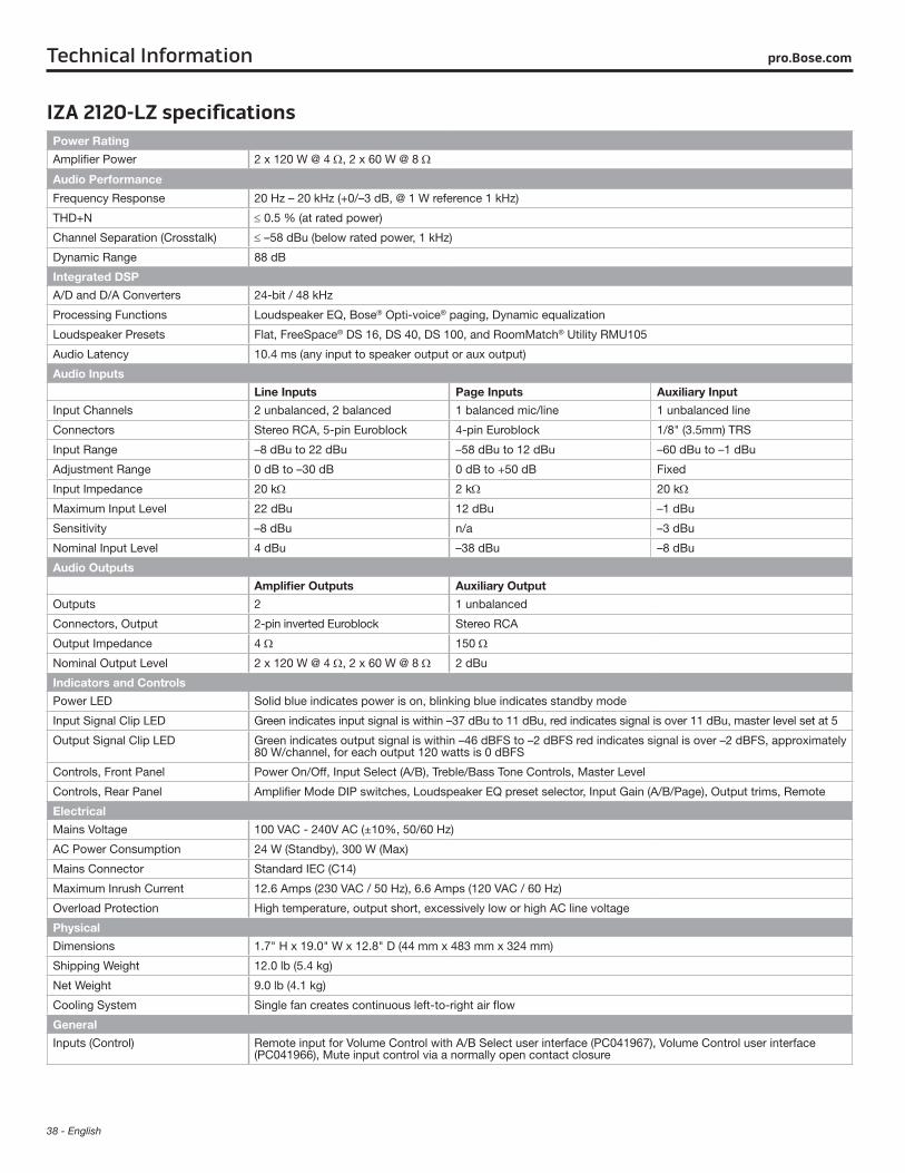
38 - English
Technical Information pro.Bose.com
IZA 2120-LZ specificationsPower Rating
Amplifier Power 2 x 120 W @ 4 Ω, 2 x 60 W @ 8 Ω
Audio Performance Frequency Response 20 Hz – 20 kHz (+0/–3 dB, @ 1 W reference 1 kHz)
THD+N ≤ 0.5 % (at rated power)
Channel Separation (Crosstalk) ≤ –58 dBu (below rated power, 1 kHz)
Dynamic Range 88 dB
Integrated DSP
A/D and D/A Converters 24-bit / 48 kHz
Processing Functions Loudspeaker EQ, Bose® Opti-voice® paging, Dynamic equalization
Loudspeaker Presets Flat, FreeSpace® DS 16, DS 40, DS 100, and RoomMatch® Utility RMU105
Audio Latency 10.4 ms (any input to speaker output or aux output)
Audio Inputs
Line Inputs Page Inputs Auxiliary Input
Input Channels 2 unbalanced, 2 balanced 1 balanced mic/line 1 unbalanced line
Connectors Stereo RCA, 5-pin Euroblock 4-pin Euroblock 1/8" (3.5mm) TRS
Input Range –8 dBu to 22 dBu –58 dBu to 12 dBu –60 dBu to –1 dBu
Adjustment Range 0 dB to –30 dB 0 dB to +50 dB Fixed
Input Impedance 20 kΩ 2 kΩ 20 kΩ
Maximum Input Level 22 dBu 12 dBu –1 dBu
Sensitivity –8 dBu n/a –3 dBu
Nominal Input Level 4 dBu –38 dBu –8 dBu
Audio Outputs
Amplifier Outputs Auxiliary Output
Outputs 2 1 unbalanced
Connectors, Output 2-pin inverted Euroblock Stereo RCA
Output Impedance 4 Ω 150 Ω
Nominal Output Level 2 x 120 W @ 4 Ω, 2 x 60 W @ 8 Ω 2 dBu
Indicators and Controls
Power LED Solid blue indicates power is on, blinking blue indicates standby mode
Input Signal Clip LED Green indicates input signal is within –37 dBu to 11 dBu, red indicates signal is over 11 dBu, master level set at 5
Output Signal Clip LED Green indicates output signal is within –46 dBFS to –2 dBFS red indicates signal is over –2 dBFS, approximately 80 W/channel, for each output 120 watts is 0 dBFS
Controls, Front Panel Power On/Off, Input Select (A/B), Treble/Bass Tone Controls, Master Level
Controls, Rear Panel Amplifier Mode DIP switches, Loudspeaker EQ preset selector, Input Gain (A/B/Page), Output trims, Remote
Electrical
Mains Voltage 100 VAC - 240V AC (±10%, 50/60 Hz)
AC Power Consumption 24 W (Standby), 300 W (Max)
Mains Connector Standard IEC (C14)
Maximum Inrush Current 12.6 Amps (230 VAC / 50 Hz), 6.6 Amps (120 VAC / 60 Hz)
Overload Protection High temperature, output short, excessively low or high AC line voltage
Physical
Dimensions 1.7" H x 19.0" W x 12.8" D (44 mm x 483 mm x 324 mm)
Shipping Weight 12.0 lb (5.4 kg)
Net Weight 9.0 lb (4.1 kg)
Cooling System Single fan creates continuous left-to-right air flow
General
Inputs (Control) Remote input for Volume Control with A/B Select user interface (PC041967), Volume Control user interface (PC041966), Mute input control via a normally open contact closure
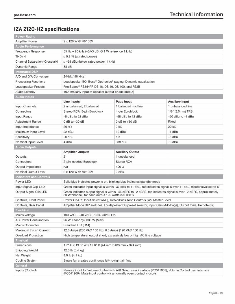
English - 39
Technical Informationpro.Bose.com
IZA 2120-HZ specificationsPower Rating
Amplifier Power 2 x 120 W @ 70/100V
Audio Performance
Frequency Response 55 Hz – 20 kHz (+0/–3 dB, @ 1 W reference 1 kHz)
THD+N ≤ 0.3 % (at rated power)
Channel Separation (Crosstalk) ≤ –58 dBu (below rated power, 1 kHz)
Dynamic Range 88 dB
Integrated DSP
A/D and D/A Converters 24-bit / 48 kHz
Processing Functions Loudspeaker EQ, Bose® Opti-voice® paging, Dynamic equalization
Loudspeaker Presets FreeSpace® FS3/HPF, DS 16, DS 40, DS 100, and FS3B
Audio Latency 10.4 ms (any input to speaker output or aux output)
Audio Inputs
Line Inputs Page Input Auxiliary Input
Input Channels 2 unbalanced, 2 balanced 1 balanced mic/line 1 unbalanced line
Connectors Stereo RCA, 5-pin Euroblock 4-pin Euroblock 1/8" (3.5mm) TRS
Input Range –8 dBu to 22 dBu –58 dBu to 12 dBu –60 dBu to –1 dBu
Adjustment Range 0 dB to –30 dB 0 dB to +50 dB Fixed
Input Impedance 20 kΩ 2 kΩ 20 kΩ
Maximum Input Level 22 dBu 12 dBu –1 dBu
Sensitivity –8 dBu n/a –3 dBu
Nominal Input Level 4 dBu –38 dBu –8 dBu
Audio Outputs
Amplifier Outputs Auxiliary Output
Outputs 2 1 unbalanced
Connectors 2-pin inverted Euroblock Stereo RCA
Output Impedance n/a 400 Ω
Nominal Output Level 2 x 120 W @ 70/100V 2 dBu
Indicators and Controls
Power LED Solid blue indicates power is on, blinking blue indicates standby mode
Input Signal Clip LED Green indicates input signal is within –37 dBu to 11 dBu, red indicates signal is over 11 dBu, master level set to 5
Output Signal Clip LED Green indicates output signal is within –46 dBFS to –2 dBFS, red indicates signal is over –2 dBFS, approximately 80 W/channel, for each output 120 watts is 0 dBFS
Controls, Front Panel Power On/Off, Input Select (A/B), Treble/Bass Tone Controls (x2), Master Level
Controls, Rear Panel Amplifier Mode DIP switches, Loudspeaker EQ preset selector, Input Gain (A/B/Page), Output trims, Remote (x2)
Electrical
Mains Voltage 100 VAC – 240 VAC (±10%, 50/60 Hz)
AC Power Consumption 26 W (Standby), 300 W (Max)
Mains Connector Standard IEC (C14)
Maximum Inrush Current 12.6 Amps (230 VAC / 50 Hz), 6.6 Amps (120 VAC / 60 Hz)
Overload Protection High temperature, output short, excessively low or high AC line voltage
Physical
Dimensions 1.7" H x 19.0" W x 12.8" D (44 mm x 483 mm x 324 mm)
Shipping Weight 12.0 lb (5.4 kg)
Net Weight 9.0 lb (4.1 kg)
Cooling System Single fan creates continuous left-to-right air flow
General
Inputs (Control) Remote input for Volume Control with A/B Select user interface (PC041967), Volume Control user interface (PC041966), Mute input control via a normally open contact closure
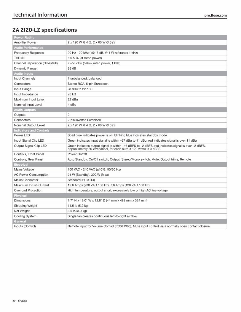
40 - English
Technical Information pro.Bose.com
ZA 2120-LZ specificationsPower Rating
Amplifier Power 2 x 120 W @ 4 Ω, 2 x 60 W @ 8 Ω
Audio Performance
Frequency Response 20 Hz - 20 kHz (+0/–3 dB, @ 1 W reference 1 kHz)
THD+N ≤ 0.5 % (at rated power)
Channel Separation (Crosstalk) ≤ –58 dBu (below rated power, 1 kHz)
Dynamic Range 88 dB
Audio Inputs
Input Channels 1 unbalanced, balanced
Connectors Stereo RCA, 5-pin Euroblock
Input Range –8 dBu to 22 dBu
Input Impedance 20 kΩ
Maximum Input Level 22 dBu
Nominal Input Level 4 dBu
Audio Outputs
Outputs 2
Connectors 2-pin inverted Euroblock
Nominal Output Level 2 x 120 W @ 4 Ω, 2 x 60 W @ 8 Ω
Indicators and Controls
Power LED Solid blue indicates power is on, blinking blue indicates standby mode
Input Signal Clip LED Green indicates input signal is within –37 dBu to 11 dBu, red indicates signal is over 11 dBu
Output Signal Clip LED Green indicates output signal is within –46 dBFS to –2 dBFS, red indicates signal is over –2 dBFS, approximately 80 W/channel, for each output 120 watts is 0 dBFS
Controls, Front Panel Power On/Off
Controls, Rear Panel Auto Standby: On/Off switch, Output: Stereo/Mono switch, Mute, Output trims, Remote
Electrical
Mains Voltage 100 VAC - 240 VAC (±10%, 50/60 Hz)
AC Power Consumption 21 W (Standby), 300 W (Max)
Mains Connector Standard IEC (C14)
Maximum Inrush Current 12.6 Amps (230 VAC / 50 Hz), 7.8 Amps (120 VAC / 60 Hz)
Overload Protection High temperature, output short, excessively low or high AC line voltage
Physical
Dimensions 1.7" H x 19.0" W x 12.8" D (44 mm x 483 mm x 324 mm)
Shipping Weight 11.5 lb (5.2 kg)
Net Weight 8.5 lb (3.9 kg)
Cooling System Single fan creates continuous left-to-right air flow
General
Inputs (Control) Remote input for Volume Control (PC041966), Mute input control via a normally open contact closure
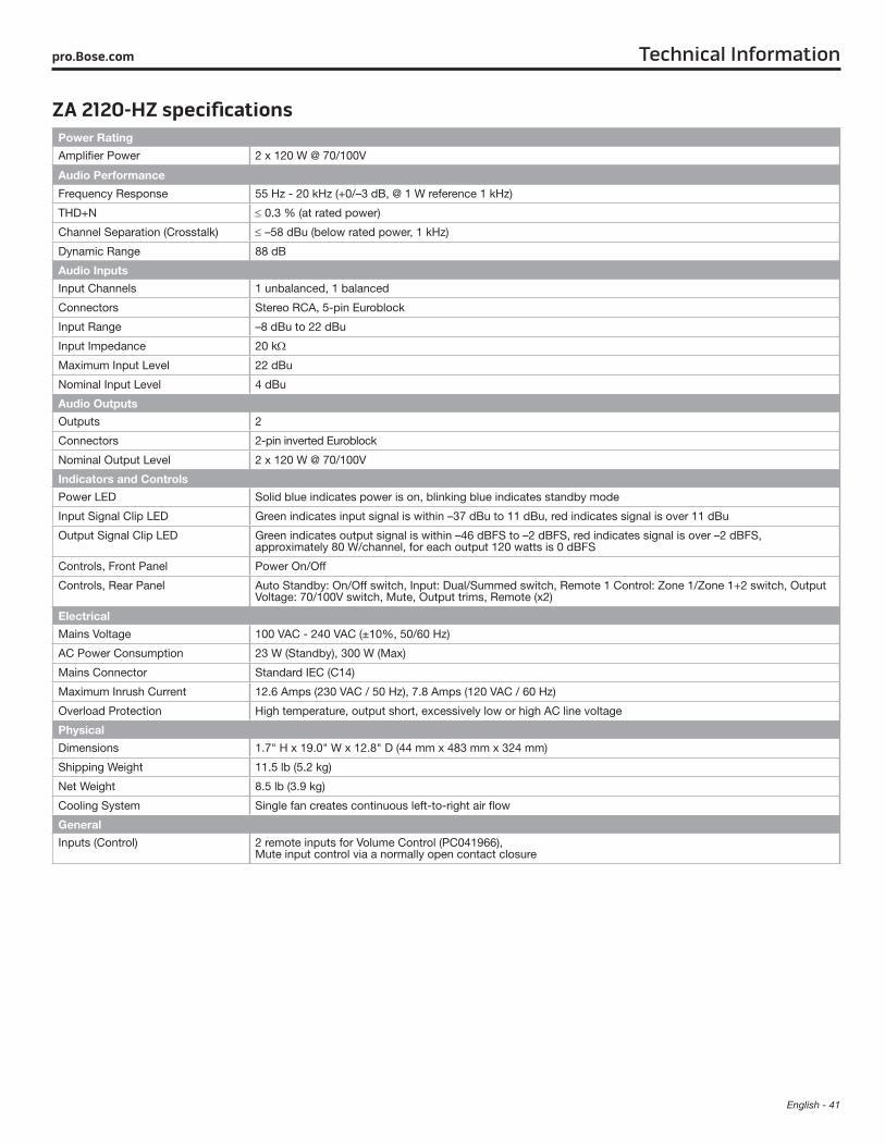
English - 41
Technical Informationpro.Bose.com
ZA 2120-HZ specificationsPower Rating
Amplifier Power 2 x 120 W @ 70/100V
Audio Performance
Frequency Response 55 Hz - 20 kHz (+0/–3 dB, @ 1 W reference 1 kHz)
THD+N ≤ 0.3 % (at rated power)
Channel Separation (Crosstalk) ≤ –58 dBu (below rated power, 1 kHz)
Dynamic Range 88 dB
Audio Inputs
Input Channels 1 unbalanced, 1 balanced
Connectors Stereo RCA, 5-pin Euroblock
Input Range –8 dBu to 22 dBu
Input Impedance 20 kΩ
Maximum Input Level 22 dBu
Nominal Input Level 4 dBu
Audio Outputs
Outputs 2
Connectors 2-pin inverted Euroblock
Nominal Output Level 2 x 120 W @ 70/100V
Indicators and Controls
Power LED Solid blue indicates power is on, blinking blue indicates standby mode
Input Signal Clip LED Green indicates input signal is within –37 dBu to 11 dBu, red indicates signal is over 11 dBu
Output Signal Clip LED Green indicates output signal is within –46 dBFS to –2 dBFS, red indicates signal is over –2 dBFS, approximately 80 W/channel, for each output 120 watts is 0 dBFS
Controls, Front Panel Power On/Off
Controls, Rear Panel Auto Standby: On/Off switch, Input: Dual/Summed switch, Remote 1 Control: Zone 1/Zone 1+2 switch, Output Voltage: 70/100V switch, Mute, Output trims, Remote (x2)
Electrical
Mains Voltage 100 VAC - 240 VAC (±10%, 50/60 Hz)
AC Power Consumption 23 W (Standby), 300 W (Max)
Mains Connector Standard IEC (C14)
Maximum Inrush Current 12.6 Amps (230 VAC / 50 Hz), 7.8 Amps (120 VAC / 60 Hz)
Overload Protection High temperature, output short, excessively low or high AC line voltage
Physical
Dimensions 1.7" H x 19.0" W x 12.8" D (44 mm x 483 mm x 324 mm)
Shipping Weight 11.5 lb (5.2 kg)
Net Weight 8.5 lb (3.9 kg)
Cooling System Single fan creates continuous left-to-right air flow
General
Inputs (Control) 2 remote inputs for Volume Control (PC041966), Mute input control via a normally open contact closure
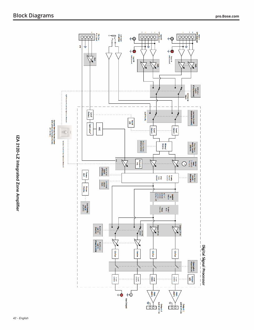
42 - English
pro.Bose.comBlock Diagrams
IZA
2120-LZ Integ
rated Z
one A
mp
lifier

English - 43
Block Diagramspro.Bose.com
IZA
212
0-H
Z In
teg
rate
d Z
one
Am
plifi
er
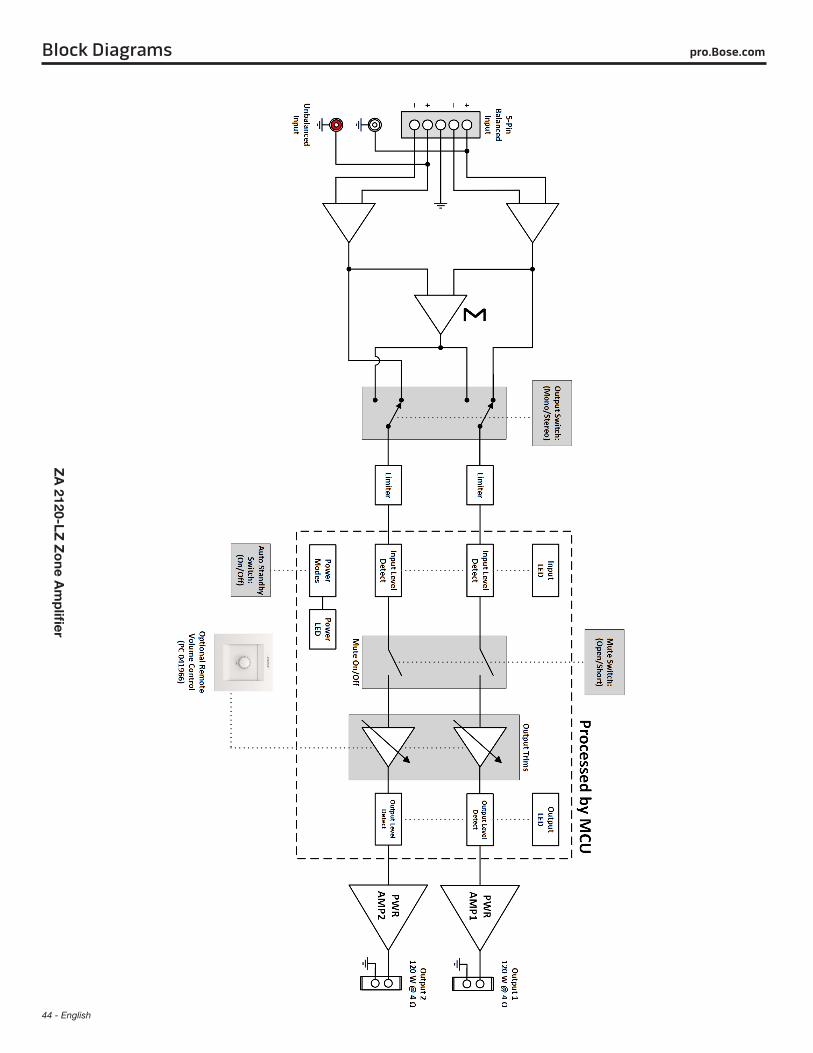
44 - English
Block Diagrams pro.Bose.com
ZA
2120-LZ Z
one A
mp
lifier
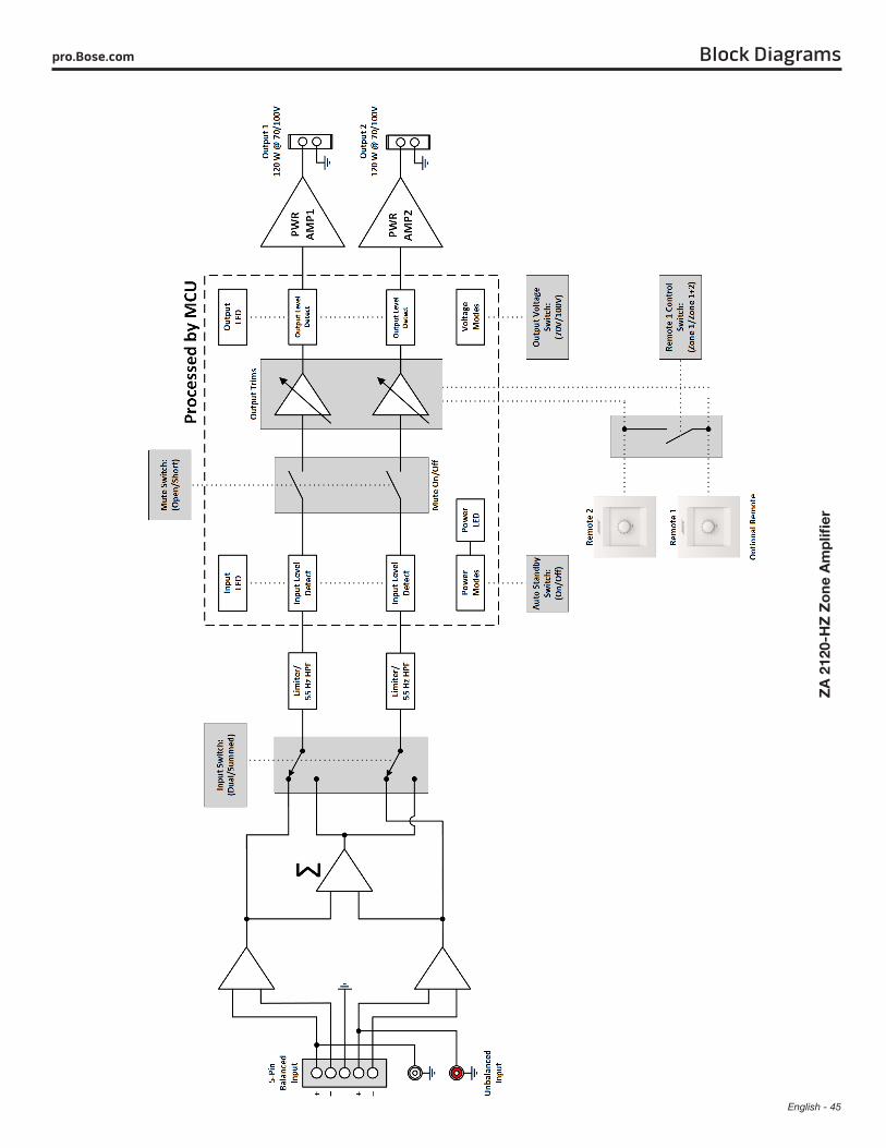
English - 45
Block Diagramspro.Bose.com
ZA
212
0-H
Z Z
one
Am
plifi
er

English - 47
pro.Bose.com Additional Resources
Visit us on the web at pro.Bose.com for more information, including specifications, technical literature, product warranty, parts and accessories, and global support contact information.
Americas (USA, Canada, Mexico, Central America, South America)Bose CorporationThe MountainFramingham, MA 01701 USACorporate Center: 508-879-7330Americas Professional Systems, Technical Support: 800-994-2673
AustraliaBose Pty LimitedUnit 3/2 Holker StreetNewington NSW Australia61 2 8737 9999
BelgiumBose N.V. / S.ALimesweg 2, 03700Tongeren, Belgium012-390800
ChinaBose Electronics (Shanghai) Co Ltd25F, L’Avenue99 Xianxia RoadShanghai, P.R.C. 200051 China86 21 6010 3800
FranceBose S.A.S12 rue de Temara 78100St. Germain-en-Laye, France01-30616363
GermanyBose GmbHMax-Planck Strasse 36D 61381Friedrichsdorf, Deutschland06172-7104-0
Hong KongBose LimitedSuites 2101-2105, Tower One, Times Square1 Matheson Street, Causeway Bay, Hong Kong852 2123 9000
IndiaBose Corporation India Private Limited Salcon Aurum, 3rd Floor Plot No. 4, Jasola District Centre New Delhi – 110025, India 91 11 43080200
ItalyBose SpA Centro Leoni A – Via G. Spadolini 5 20122 Milano, Italy 39-02-36704500
JapanBose Kabushiki Kaisha Sumitomo Fudosan Shibuya Garden Tower 5F 16-17, Nanpeidai-cho Shibuya-Ku, Tokyo, 150-0036, JapanTEL 81-3-5489-0955 www.bose.co.jp
The NetherlandsBose BVNijverheidstraat 8 1135 GEEdam, Nederland0299-390139
United KingdomBose Ltd1 Ambley Green, Gillingham Business Park KENT ME8 0NJGillingham, England0870-741-4500
See website for other countries

© 2015 Bose Corporation, The Mountain, Framingham, MA 01701-9168 USApro.Bose.comAM747973 Rev. 01