Freescale ZigBee™ Application -...
92
Document Number: ZAUGZB2007 Rev. 1.1 10/2008 Freescale ZigBee™ Application User’s Guide for ZigBee 2007
Transcript of Freescale ZigBee™ Application -...

Document Number: ZAUGZB2007Rev. 1.1 10/2008
Freescale ZigBee™ ApplicationUser’s Guide for ZigBee 2007

How to Reach Us:
Home Page:www.freescale.com
E-mail:[email protected]
USA/Europe or Locations Not Listed:Freescale SemiconductorTechnical Information Center, CH3701300 N. Alma School RoadChandler, Arizona 85224+1-800-521-6274 or [email protected]
Europe, Middle East, and Africa:Freescale Halbleiter Deutschland GmbHTechnical Information CenterSchatzbogen 781829 Muenchen, Germany+44 1296 380 456 (English)+46 8 52200080 (English)+49 89 92103 559 (German)+33 1 69 35 48 48 (French)[email protected]
Japan:Freescale Semiconductor Japan Ltd.HeadquartersARCO Tower 15F1-8-1, Shimo-Meguro, Meguro-ku,Tokyo 153-0064, Japan0120 191014 or +81 3 5437 [email protected]
Asia/Pacific:Freescale Semiconductor Hong Kong Ltd.Technical Information Center2 Dai King StreetTai Po Industrial EstateTai Po, N.T., Hong Kong+800 2666 [email protected]
For Literature Requests Only:Freescale Semiconductor Literature Distribution CenterP.O. Box 5405Denver, Colorado 802171-800-521-6274 or 303-675-2140Fax: [email protected]
Information in this document is provided solely to enable system and software implementers to use Freescale Semiconductor products. There are no express or implied copyright licenses granted hereunder to design or fabricate any integrated circuits or integrated circuits based on the information in this document.Freescale Semiconductor reserves the right to make changes without further notice to any products herein. Freescale Semiconductor makes no warranty, representation or guarantee regarding the suitability of its products for any particular purpose, nor does Freescale Semiconductor assume any liability arising out of the application or use of any product or circuit, and specifically disclaims any and all liability, including without limitation consequential or incidental damages. “Typical” parameters that may be provided in Freescale Semiconductor data sheets and/or specifications can and do vary in different applications and actual performance may vary over time. All operating parameters, including “Typicals”, must be validated for each customer application by customer’s technical experts. Freescale Semiconductor does not convey any license under its patent rights nor the rights of others. Freescale Semiconductor products are not designed, intended, or authorized for use as components in systems intended for surgical implant into the body, or other applications intended to support or sustain life, or for any other application in which the failure of the Freescale Semiconductor product could create a situation where personal injury or death may occur. Should Buyer purchase or use Freescale Semiconductor products for any such unintended or unauthorized application, Buyer shall indemnify and hold Freescale Semiconductor and its officers, employees, subsidiaries, affiliates, and distributors harmless against all claims, costs, damages, and expenses, and reasonable attorney fees arising out of, directly or indirectly, any claim of personal injury or death associated with such unintended or unauthorized use, even if such claim alleges that Freescale Semiconductor was negligent regarding the design or manufacture of the part.
Freescale™ and the Freescale logo are trademarks of Freescale Semiconductor, Inc. All other product or service names are the property of their respective owners.
© Freescale Semiconductor, Inc. 2006, 2007, 2008. All rights reserved.
Freescale ZigBee™ Application User’s Guide for ZigBee 2007, Rev. 1.1
Freescale Semiconductor i
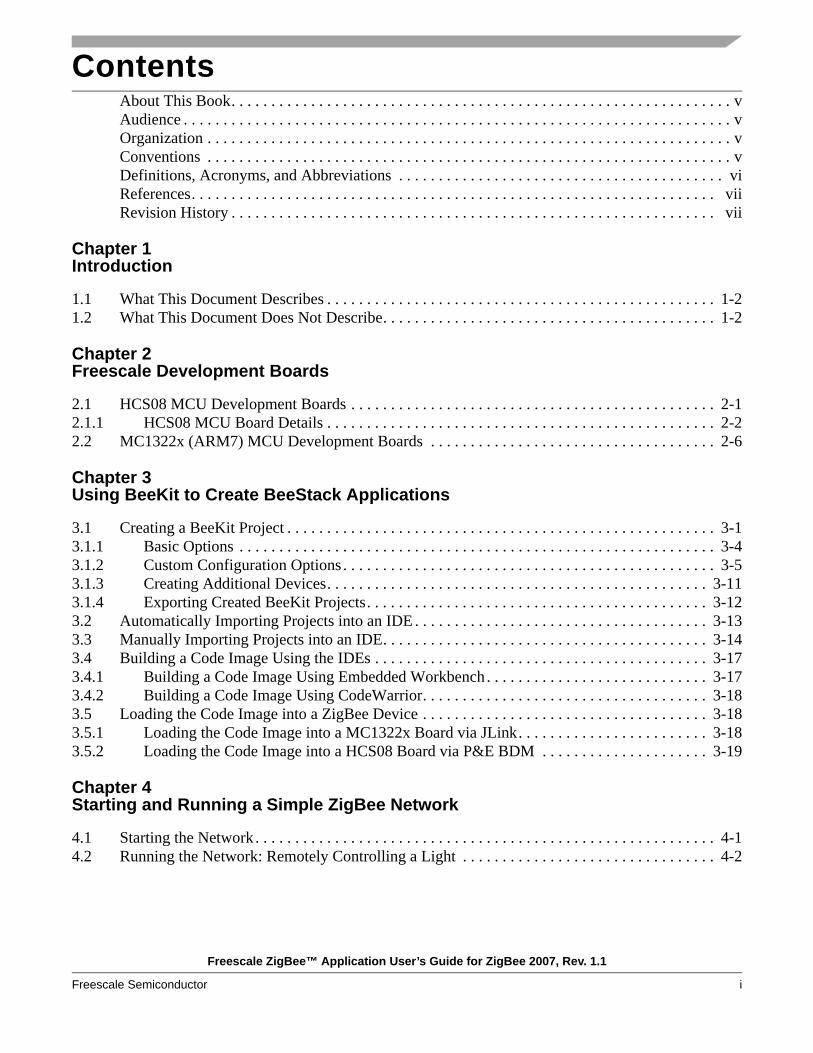
ContentsAbout This Book. . . . . . . . . . . . . . . . . . . . . . . . . . . . . . . . . . . . . . . . . . . . . . . . . . . . . . . . . . . . . . . vAudience . . . . . . . . . . . . . . . . . . . . . . . . . . . . . . . . . . . . . . . . . . . . . . . . . . . . . . . . . . . . . . . . . . . . . vOrganization . . . . . . . . . . . . . . . . . . . . . . . . . . . . . . . . . . . . . . . . . . . . . . . . . . . . . . . . . . . . . . . . . . vConventions . . . . . . . . . . . . . . . . . . . . . . . . . . . . . . . . . . . . . . . . . . . . . . . . . . . . . . . . . . . . . . . . . . vDefinitions, Acronyms, and Abbreviations . . . . . . . . . . . . . . . . . . . . . . . . . . . . . . . . . . . . . . . . . viReferences. . . . . . . . . . . . . . . . . . . . . . . . . . . . . . . . . . . . . . . . . . . . . . . . . . . . . . . . . . . . . . . . . . viiRevision History . . . . . . . . . . . . . . . . . . . . . . . . . . . . . . . . . . . . . . . . . . . . . . . . . . . . . . . . . . . . . vii
Chapter 1 Introduction
1.1 What This Document Describes . . . . . . . . . . . . . . . . . . . . . . . . . . . . . . . . . . . . . . . . . . . . . . . . . 1-21.2 What This Document Does Not Describe. . . . . . . . . . . . . . . . . . . . . . . . . . . . . . . . . . . . . . . . . . 1-2
Chapter 2 Freescale Development Boards
2.1 HCS08 MCU Development Boards . . . . . . . . . . . . . . . . . . . . . . . . . . . . . . . . . . . . . . . . . . . . . . 2-12.1.1 HCS08 MCU Board Details . . . . . . . . . . . . . . . . . . . . . . . . . . . . . . . . . . . . . . . . . . . . . . . . . 2-22.2 MC1322x (ARM7) MCU Development Boards . . . . . . . . . . . . . . . . . . . . . . . . . . . . . . . . . . . . 2-6
Chapter 3 Using BeeKit to Create BeeStack Applications
3.1 Creating a BeeKit Project . . . . . . . . . . . . . . . . . . . . . . . . . . . . . . . . . . . . . . . . . . . . . . . . . . . . . . 3-13.1.1 Basic Options . . . . . . . . . . . . . . . . . . . . . . . . . . . . . . . . . . . . . . . . . . . . . . . . . . . . . . . . . . . . 3-43.1.2 Custom Configuration Options . . . . . . . . . . . . . . . . . . . . . . . . . . . . . . . . . . . . . . . . . . . . . . . 3-53.1.3 Creating Additional Devices. . . . . . . . . . . . . . . . . . . . . . . . . . . . . . . . . . . . . . . . . . . . . . . . 3-113.1.4 Exporting Created BeeKit Projects. . . . . . . . . . . . . . . . . . . . . . . . . . . . . . . . . . . . . . . . . . . 3-123.2 Automatically Importing Projects into an IDE . . . . . . . . . . . . . . . . . . . . . . . . . . . . . . . . . . . . . 3-133.3 Manually Importing Projects into an IDE. . . . . . . . . . . . . . . . . . . . . . . . . . . . . . . . . . . . . . . . . 3-143.4 Building a Code Image Using the IDEs . . . . . . . . . . . . . . . . . . . . . . . . . . . . . . . . . . . . . . . . . . 3-173.4.1 Building a Code Image Using Embedded Workbench . . . . . . . . . . . . . . . . . . . . . . . . . . . . 3-173.4.2 Building a Code Image Using CodeWarrior. . . . . . . . . . . . . . . . . . . . . . . . . . . . . . . . . . . . 3-183.5 Loading the Code Image into a ZigBee Device . . . . . . . . . . . . . . . . . . . . . . . . . . . . . . . . . . . . 3-183.5.1 Loading the Code Image into a MC1322x Board via JLink. . . . . . . . . . . . . . . . . . . . . . . . 3-183.5.2 Loading the Code Image into a HCS08 Board via P&E BDM . . . . . . . . . . . . . . . . . . . . . 3-19
Chapter 4 Starting and Running a Simple ZigBee Network
4.1 Starting the Network. . . . . . . . . . . . . . . . . . . . . . . . . . . . . . . . . . . . . . . . . . . . . . . . . . . . . . . . . . 4-14.2 Running the Network: Remotely Controlling a Light . . . . . . . . . . . . . . . . . . . . . . . . . . . . . . . . 4-2
Freescale ZigBee™ Application User’s Guide for ZigBee 2007, Rev. 1.1
ii Freescale Semiconductor
Chapter 5 Creating a Wireless UART Application
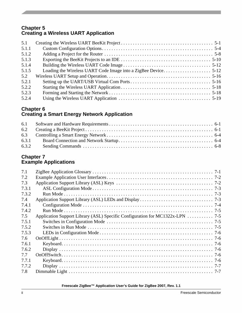
5.1 Creating the Wireless UART BeeKit Project . . . . . . . . . . . . . . . . . . . . . . . . . . . . . . . . . . . . . . . 5-15.1.1 Custom Configuration Options . . . . . . . . . . . . . . . . . . . . . . . . . . . . . . . . . . . . . . . . . . . . . . . 5-45.1.2 Adding a Project for the Router . . . . . . . . . . . . . . . . . . . . . . . . . . . . . . . . . . . . . . . . . . . . . . 5-85.1.3 Exporting the BeeKit Projects to an IDE . . . . . . . . . . . . . . . . . . . . . . . . . . . . . . . . . . . . . . 5-105.1.4 Building the Wireless UART Code Image . . . . . . . . . . . . . . . . . . . . . . . . . . . . . . . . . . . . . 5-125.1.5 Loading the Wireless UART Code Image into a ZigBee Device. . . . . . . . . . . . . . . . . . . . 5-125.2 Wireless UART Setup and Operation. . . . . . . . . . . . . . . . . . . . . . . . . . . . . . . . . . . . . . . . . . . . 5-165.2.1 Setting up the UART/USB Virtual Com Ports . . . . . . . . . . . . . . . . . . . . . . . . . . . . . . . . . . 5-165.2.2 Starting the Wireless UART Application . . . . . . . . . . . . . . . . . . . . . . . . . . . . . . . . . . . . . . 5-185.2.3 Forming and Starting the Network . . . . . . . . . . . . . . . . . . . . . . . . . . . . . . . . . . . . . . . . . . . 5-185.2.4 Using the Wireless UART Application . . . . . . . . . . . . . . . . . . . . . . . . . . . . . . . . . . . . . . . 5-19
Chapter 6 Creating a Smart Energy Network Application
6.1 Software and Hardware Requirements . . . . . . . . . . . . . . . . . . . . . . . . . . . . . . . . . . . . . . . . . . . . 6-16.2 Creating a BeeKit Project . . . . . . . . . . . . . . . . . . . . . . . . . . . . . . . . . . . . . . . . . . . . . . . . . . . . . . 6-16.3 Controlling a Smart Energy Network . . . . . . . . . . . . . . . . . . . . . . . . . . . . . . . . . . . . . . . . . . . . . 6-46.3.1 Board Connection and Network Startup. . . . . . . . . . . . . . . . . . . . . . . . . . . . . . . . . . . . . . . . 6-46.3.2 Sending Commands . . . . . . . . . . . . . . . . . . . . . . . . . . . . . . . . . . . . . . . . . . . . . . . . . . . . . . . 6-8
Chapter 7 Example Applications
7.1 ZigBee Application Glossary . . . . . . . . . . . . . . . . . . . . . . . . . . . . . . . . . . . . . . . . . . . . . . . . . . . 7-17.2 Example Application User Interfaces . . . . . . . . . . . . . . . . . . . . . . . . . . . . . . . . . . . . . . . . . . . . . 7-27.3 Application Support Library (ASL) Keys . . . . . . . . . . . . . . . . . . . . . . . . . . . . . . . . . . . . . . . . . 7-27.3.1 ASL Configuration Mode . . . . . . . . . . . . . . . . . . . . . . . . . . . . . . . . . . . . . . . . . . . . . . . . . . . 7-37.3.2 Run Mode . . . . . . . . . . . . . . . . . . . . . . . . . . . . . . . . . . . . . . . . . . . . . . . . . . . . . . . . . . . . . . . 7-37.4 Application Support Library (ASL) LEDs and Display . . . . . . . . . . . . . . . . . . . . . . . . . . . . . . . 7-37.4.1 Configuration Mode . . . . . . . . . . . . . . . . . . . . . . . . . . . . . . . . . . . . . . . . . . . . . . . . . . . . . . . 7-47.4.2 Run Mode . . . . . . . . . . . . . . . . . . . . . . . . . . . . . . . . . . . . . . . . . . . . . . . . . . . . . . . . . . . . . . . 7-57.5 Application Support Library (ASL) Specific Configuration for MC1322x-LPN . . . . . . . . . . . 7-57.5.1 Switches in Configuration Mode . . . . . . . . . . . . . . . . . . . . . . . . . . . . . . . . . . . . . . . . . . . . . 7-57.5.2 Switches in Run Mode . . . . . . . . . . . . . . . . . . . . . . . . . . . . . . . . . . . . . . . . . . . . . . . . . . . . . 7-57.5.3 LEDs in Configuration Mode . . . . . . . . . . . . . . . . . . . . . . . . . . . . . . . . . . . . . . . . . . . . . . . . 7-67.6 OnOffLight . . . . . . . . . . . . . . . . . . . . . . . . . . . . . . . . . . . . . . . . . . . . . . . . . . . . . . . . . . . . . . . . . 7-67.6.1 Keyboard. . . . . . . . . . . . . . . . . . . . . . . . . . . . . . . . . . . . . . . . . . . . . . . . . . . . . . . . . . . . . . . . 7-67.6.2 Display . . . . . . . . . . . . . . . . . . . . . . . . . . . . . . . . . . . . . . . . . . . . . . . . . . . . . . . . . . . . . . . . . 7-67.7 OnOffSwitch. . . . . . . . . . . . . . . . . . . . . . . . . . . . . . . . . . . . . . . . . . . . . . . . . . . . . . . . . . . . . . . . 7-67.7.1 Keyboard. . . . . . . . . . . . . . . . . . . . . . . . . . . . . . . . . . . . . . . . . . . . . . . . . . . . . . . . . . . . . . . . 7-67.7.2 Display . . . . . . . . . . . . . . . . . . . . . . . . . . . . . . . . . . . . . . . . . . . . . . . . . . . . . . . . . . . . . . . . . 7-77.8 Dimmable Light . . . . . . . . . . . . . . . . . . . . . . . . . . . . . . . . . . . . . . . . . . . . . . . . . . . . . . . . . . . . . 7-7

Freescale ZigBee™ Application User’s Guide for ZigBee 2007, Rev. 1.1
Freescale Semiconductor iii
7.8.1 Keyboard. . . . . . . . . . . . . . . . . . . . . . . . . . . . . . . . . . . . . . . . . . . . . . . . . . . . . . . . . . . . . . . . 7-77.8.2 Display . . . . . . . . . . . . . . . . . . . . . . . . . . . . . . . . . . . . . . . . . . . . . . . . . . . . . . . . . . . . . . . . . 7-77.9 Dimmer Control Switch . . . . . . . . . . . . . . . . . . . . . . . . . . . . . . . . . . . . . . . . . . . . . . . . . . . . . . . 7-77.9.1 Keyboard. . . . . . . . . . . . . . . . . . . . . . . . . . . . . . . . . . . . . . . . . . . . . . . . . . . . . . . . . . . . . . . . 7-77.9.2 Display . . . . . . . . . . . . . . . . . . . . . . . . . . . . . . . . . . . . . . . . . . . . . . . . . . . . . . . . . . . . . . . . . 7-87.10 Thermostat . . . . . . . . . . . . . . . . . . . . . . . . . . . . . . . . . . . . . . . . . . . . . . . . . . . . . . . . . . . . . . . . . 7-87.10.1 Keyboard. . . . . . . . . . . . . . . . . . . . . . . . . . . . . . . . . . . . . . . . . . . . . . . . . . . . . . . . . . . . . . . . 7-87.10.2 Display . . . . . . . . . . . . . . . . . . . . . . . . . . . . . . . . . . . . . . . . . . . . . . . . . . . . . . . . . . . . . . . . . 7-87.11 Temperature Sensor . . . . . . . . . . . . . . . . . . . . . . . . . . . . . . . . . . . . . . . . . . . . . . . . . . . . . . . . . . 7-97.11.1 Keyboard. . . . . . . . . . . . . . . . . . . . . . . . . . . . . . . . . . . . . . . . . . . . . . . . . . . . . . . . . . . . . . . . 7-97.11.2 Display . . . . . . . . . . . . . . . . . . . . . . . . . . . . . . . . . . . . . . . . . . . . . . . . . . . . . . . . . . . . . . . . . 7-97.12 HA Generic Application . . . . . . . . . . . . . . . . . . . . . . . . . . . . . . . . . . . . . . . . . . . . . . . . . . . . . . . 7-97.13 HA Range Extender . . . . . . . . . . . . . . . . . . . . . . . . . . . . . . . . . . . . . . . . . . . . . . . . . . . . . . . . . . 7-97.14 HA Combined Interface . . . . . . . . . . . . . . . . . . . . . . . . . . . . . . . . . . . . . . . . . . . . . . . . . . . . . . 7-107.15 Energy Service Portal (ESP). . . . . . . . . . . . . . . . . . . . . . . . . . . . . . . . . . . . . . . . . . . . . . . . . . . 7-107.16 Metering Device . . . . . . . . . . . . . . . . . . . . . . . . . . . . . . . . . . . . . . . . . . . . . . . . . . . . . . . . . . . . 7-107.16.1 Keyboard. . . . . . . . . . . . . . . . . . . . . . . . . . . . . . . . . . . . . . . . . . . . . . . . . . . . . . . . . . . . . . . 7-107.16.2 Display . . . . . . . . . . . . . . . . . . . . . . . . . . . . . . . . . . . . . . . . . . . . . . . . . . . . . . . . . . . . . . . . 7-117.17 In-Premise Display . . . . . . . . . . . . . . . . . . . . . . . . . . . . . . . . . . . . . . . . . . . . . . . . . . . . . . . . . . 7-117.17.1 Keyboard. . . . . . . . . . . . . . . . . . . . . . . . . . . . . . . . . . . . . . . . . . . . . . . . . . . . . . . . . . . . . . . 7-117.17.2 Display . . . . . . . . . . . . . . . . . . . . . . . . . . . . . . . . . . . . . . . . . . . . . . . . . . . . . . . . . . . . . . . . 7-117.18 Programmable Communicating Thermostat (PCT) . . . . . . . . . . . . . . . . . . . . . . . . . . . . . . . . . 7-127.18.1 Keyboard. . . . . . . . . . . . . . . . . . . . . . . . . . . . . . . . . . . . . . . . . . . . . . . . . . . . . . . . . . . . . . . 7-127.18.2 Display . . . . . . . . . . . . . . . . . . . . . . . . . . . . . . . . . . . . . . . . . . . . . . . . . . . . . . . . . . . . . . . . 7-127.19 Range Extender. . . . . . . . . . . . . . . . . . . . . . . . . . . . . . . . . . . . . . . . . . . . . . . . . . . . . . . . . . . . . 7-127.20 Load Control, Smart Appliance, Prepayment Terminal . . . . . . . . . . . . . . . . . . . . . . . . . . . . . . 7-137.21 Manufacturer Specific Applications . . . . . . . . . . . . . . . . . . . . . . . . . . . . . . . . . . . . . . . . . . . . . 7-137.21.1 Manufacturer Specific Configuration Mode User Interface . . . . . . . . . . . . . . . . . . . . . . . . 7-137.22 Wireless UART. . . . . . . . . . . . . . . . . . . . . . . . . . . . . . . . . . . . . . . . . . . . . . . . . . . . . . . . . . . . . 7-147.22.1 Keyboard. . . . . . . . . . . . . . . . . . . . . . . . . . . . . . . . . . . . . . . . . . . . . . . . . . . . . . . . . . . . . . . 7-147.22.2 Display . . . . . . . . . . . . . . . . . . . . . . . . . . . . . . . . . . . . . . . . . . . . . . . . . . . . . . . . . . . . . . . . 7-147.22.3 Baud Rate Display User Interface . . . . . . . . . . . . . . . . . . . . . . . . . . . . . . . . . . . . . . . . . . . 7-157.23 Generic App . . . . . . . . . . . . . . . . . . . . . . . . . . . . . . . . . . . . . . . . . . . . . . . . . . . . . . . . . . . . . . . 7-157.23.1 Keyboard. . . . . . . . . . . . . . . . . . . . . . . . . . . . . . . . . . . . . . . . . . . . . . . . . . . . . . . . . . . . . . . 7-167.23.2 Display . . . . . . . . . . . . . . . . . . . . . . . . . . . . . . . . . . . . . . . . . . . . . . . . . . . . . . . . . . . . . . . . 7-16

Freescale ZigBee™ Application User’s Guide for ZigBee 2007, Rev. 1.1
iv Freescale Semiconductor

Freescale ZigBee™ Application User’s Guide for ZigBee 2007, Rev. 1.1
Freescale Semiconductor v
About This BookThe ZigBee Application User’s Guide for ZigBee 2007 explains how to install and run the ZigBee Feature Set example applications that are included in Freescale’s BeeKit Wireless Connectivity Toolkit for ZigBee 2007 compliant applications.
AudienceThis document is the operator’s manual for the ZigBee example applications in BeeKit. Anyone needing to demonstrate the applications or to become familiar with their behavior should read this manual. ZigBee application developers should read this manual along with the ZigBee Application Development Guide for ZigBee 2007 to understand what the applications do and how they do it.
OrganizationThis document is organized into the following sections.Chapter 1 Introduction – introduces the Freescale implementation of ZigBee wireless sensor
networks.Chapter 2 Freescale Development Boards – provides detailed installation and device configuration in-
formation using the Freescale BeeKit Wireless Connectivity Toolkit tools.Chapter 3 BeeKit and CodeWarrior – provides a simple home lighting control network to introduce
users to simple ZigBee applications.Chapter 4 Starting and Running a Simple ZigBee Network – provides a quick tutorial to form a Zig-
Bee network using code built and loaded into two development boards in previous chapters.Chapter 5 Creating a Wireless UART Application - shows how to create a Freescale Wireless UART
application using the Freescale BeeKit Wireless Connectivity Toolkit.Chapter 6 Creating a Smart Energy Network Application - shows how to create a Smart Energy Net-
work consisting of three different applications using the Freescale BeeKit Wireless Con-nectivity Toolkit.
Chapter 7 Example Applications – provides several examples to allow users to configure and run ZigBee wireless home control applications.
ConventionsThis document uses the following conventions:Courier Is used to identify commands, explicit command parameters, code examples,
expressions, data types, and directives.Italic Is used for emphasis, to identify new terms, and for replaceable command
parameters.
All source code examples are in C.

Freescale ZigBee™ Application User’s Guide for ZigBee 2007, Rev. 1.1
vi Freescale Semiconductor
Definitions, Acronyms, and AbbreviationsAPS Application Support sub-layer, a ZigBee stack componentAPL Application Layer, a ZigBee stack componentBDM Background Debug Mode: The HCS08 MCUs used here have a BDM port that
allows a computer to program its flash memory and control the MCU's operation. The computer connects to the MCU through a hardware device called a BDM pod. In this application, the pod is the P&E USB HCS08/HCS12 Multilink
BeeKit Freescale Wireless Connectivity Toolkit networking softwareBinding Associating two nodes in a network for specific functions (e.g., a light and switch)Cluster A collection of attributes accompanying a specific cluster identifier (sub-type
messages.)EVB Evaluation Board, a Freescale development board. GUI Graphical User Interface: BeeKit and CodeWarrior, the two Windows tools
discussed here, each uses a GUIHCS08 A member of one of Freescale's families of MCUsIDE Integrated Development Environment: A computer program that contains most or
all of the tools to develop code, including an editor, compiler, linker, and debuggerMAC IEEE 802.15.4 Medium Access Control sub-layerMCU Micro Controller Unit: A microprocessor combined with peripherals, typically
including memory, in one package or on one dieNCB Network Coordinator Board, a Freescale development boardNN 1322x Network Node, a Freescale development boardNode A device or group of devices with a single radioNWK Network Layer, a ZigBee stack componentOUI Organizational Unique Identifier (The IEEE-assigned 24 most significant bits of
the 64-bit MAC address)PAN Personal Area NetworkProfile Set of options in a stack or an application1320x-QE128EVB 1320x-QE128 Evaluation Board, a Freescale development board with an
MC1320x transceiver and an MC9S08QE128 MCUSARD Sensor Application Reference Design, a Freescale development boardSN 1322x Sensor Node, a Freescale development boardSMAC Freescale Simple MAC, a very simple, very small proprietary wireless protocol
that uses the Freescale IEEE 802.15.4 radiosSRB Sensor Reference Board, a Freescale development boardSCI Serial Communication Interface. This is a hardware serial port on the HCS08.
With the addition of an external level shifter, it can be used as an RS232 port

Freescale ZigBee™ Application User’s Guide for ZigBee 2007, Rev. 1.1
Freescale Semiconductor vii
SPI Serial Peripheral Interface. This is a serial port intended to connect integrated circuits that are together on one circuit board
SSP Security Service Provider, a ZigBee stack componentStack ZigBee protocol stackToggle A toggle switch moves from one state to its other state each time it is toggled. For
instance, if the first toggle takes the switch to Off, the next toggle will be to On, and the one after that will be to Off again. In the applications this document describes, the switches are momentary push buttons with no memory of their states. The HCS08 maintains each switch's state
UART Universal Asynchronous Receiver Transmitter, an MCU peripheral for access to devices not on the same circuit board. With level shifting, the UART implements RS-232
UI User InterfaceZC ZigBee Coordinator: one of the three roles a node can have in a ZigBee networkZED ZigBee End Device: one of the three roles a node can have in a ZigBee networkZR ZigBee Router: one of the three roles a node can have in a ZigBee network802.15.4 An IEEE standard radio specification that underlies the ZigBee specification
ReferencesThe following documents were referenced to build this document.
1. Freescale BeeStack Software Reference Manual, Document BSSRM, February 2007.2. Document 053474r17, ZigBee Specification, ZigBee Alliance, October 20073. Document 075123r00, ZigBee Cluster Library Specification, ZigBee Alliance, July 20074. Document 053520r24, Home Automation Profile Specification, ZigBee Alliance, September 20075. The data sheets for the MC13193, MC13203, MC1321x radios6. Freescale MC9S08GB/GT Data Sheet, Document MC9S08GB60, December 2004
Revision HistoryThe following table summarizes revisions to this manual since the previous release (Rev. 1.0).
Revision History
Location Revisions
Entire document Updated for MC1322x EVK release.

Freescale ZigBee™ Application User’s Guide for ZigBee 2007, Rev. 1.1
viii Freescale Semiconductor

Freescale ZigBee™ Application User’s Guide for ZigBee 2007, Rev. 1.1
Freescale Semiconductor 1-1
Chapter 1 Introduction
The Freescale BeeKit Wireless Connectivity Toolkit includes a set of example applications for the ZigBee Feature Set using the Home Automation application profile, supplemented by Accelerometer and Wireless UART example applications. This guide also describes the ZigBee Pro Feature Set that uses the Smart Energy application profile. This user’s guide describes how to:
• Configure the applications in BeeKit for any of the Freescale development boards that BeeKit supports
• Export the configured applications from BeeKit• Import the configured applications into either Freescale CodeWarrior or IAR Embedded
Workbench• Build the applications in CodeWarrior or Embedded Workbench Integrated Development
Environments (IDEs)• Load the applications into Freescale development boards using either a BDM or JLink pod• Run the applications on the boards
These applications require the installation of the BeeKit Wireless Connectivity Toolkit, including the BeeStack Codebases, and either CodeWarrior for the HCS08, version 6.1 or later for HCS08 based development or IAR Embedded Workbench version 5.20 or later for ARM7 based development. They also require a P&E Multilink Background Debug Mode pod for the HCS08 or a JLink JTAG pod for ARM7 to program the development boards. This document assumes that all of these are correctly installed.
This user’s guide assumes familiarity with the purpose and major features of ZigBee Wireless Networks. It explains only enough of BeeKit and the IDEs to get the applications loaded to the development boards. These much larger topics are explained in the appropriate reference manuals and ZigBee/802,15,4 specifications.

Introduction
Freescale ZigBee™ Application User’s Guide for ZigBee 2007, Rev. 1.1
1-2 Freescale Semiconductor
1.1 What This Document DescribesThis document explains how to:
• Get the example ZigBee applications in BeeKit into Freescale development boards• Run the applications
1.2 What This Document Does Not DescribeThis document does not explain how to:
• Install BeeKit or the IDEs• Understand or modify the application code• Port the applications or BeeStack to a platform that BeeKit does not already support• Learn about ZigBee. For a tutorial on ZigBee, go to www.freescale.com/zigbee and click on Online
Training

Freescale ZigBee™ Application User’s Guide for ZigBee 2007, Rev. 1.1
Freescale Semiconductor 2-1
Chapter 2 Freescale Development Boards
2.1 HCS08 MCU Development BoardsThe following development boards are based on the Freescale HCS08 based ZigBee transceivers:
• Network Coordinator Board (MC1321x-NCB)• Sensor Reference Board (MC1321x-SRB)• Evaluation Board for QE128 MCUs (1320x-QE128EVB)• Axiom GB60 (AXM-0308)• Sensor Application Reference Design (MC1319x-SARD)• MC1319x Evaluation Board (MC1319x-EVB)
NOTEThe AXM-0308, MC1319x-SARD and MC1319x-EVB are no longer supported using standard configuration in BeeKit. Use the BeeKit HCS08 platform editor in the MAC and BeeStack codebases to configure platform settings that are based on the defaults for these boards.
Table 2-1. Freescale HCS08 Development Boards
Board Number Device Type Serial Interface Board Features
MC1321x-NCB MC13213 (SiP using MC68HCS908GT60)
USB and RS232 LCD with two 16-character rows, PWM-driven speaker
MC1321x-SRB MC13213 (SiP using MC68HCS908GT60)
USB 3-axis accelerometer, temperature sensor, PWM-driven speaker
1320x-QE128EVB MC13202 and socket for QE128 MCUs such as Flexis 8-bit MC9S08QE128
USB and RS232 LCD with two 16-character rows
AXM-0308 MC13193 and MC68HCS908GB60
RS232 RF is on a daughter card
MC1319x-SARD MC13193 and MC68HCS908GT60
RS232 3-axis accelerometer
MC1319x-EVB MC13193 and MC68HCS908GT60
USB and RS232

Freescale Development Boards
Freescale ZigBee™ Application User’s Guide for ZigBee 2007, Rev. 1.1
2-2 Freescale Semiconductor
2.1.1 HCS08 MCU Board DetailsEach of these boards has:
• a Freescale HCS08 MCU:— 60KB flash for GB/GT60 MCUs or 128 KB flash for MC9S08QE128— 4KB static RAM for GB/GT60 MCUs or up to 8KB for MC9S08QE128— Two Serial Communication Interface (SCI) ports
– If a board has an RS232 connector, it uses SCI 1– If a board has a USB connector or a 2nd RS232 connector, it uses SCI 2
— One Serial Peripheral Interface (SPI) port connected to the ZigBee radio• Four push button switches (S1-S4 or SW2-SW5 on 1320x-QE128EVB) on MCU input pins. Pin
assignments are not identical across all boards• Four LEDs (LED1-LED4) on MCU output pins. Pin assignments are not identical across all boards• A six-pin Background Debug Mode (BDM) connector for programming the flash and using the
debugger
The applications use the four switches and the four LEDs identically on all boards even though the pin assignments differ, as explained in the next chapter.
The 1320x-QE128EVB, EVB, NCB, and SRB have a USB-UART translator circuit. That does not affect the code on the MCU (the USB port looks like an RS232 port), but the USB port can power the board, and it is easier to connect more than a few boards to a computer if they use USB. The boards are shown in the following figures.
Figure 2-1. MC1321x-NCB
USBConnector
SerialConnector
PowerConnector
On/OffSwitch
ResetButton
LED1SW1
LED2SW2
LED3SW3
LED4SW4
BDMConnector

Freescale Development Boards
Freescale ZigBee™ Application User’s Guide for ZigBee 2007, Rev. 1.1
Freescale Semiconductor 2-3
Figure 2-2. SRB Evaluation Board
Figure 2-3. 1320x-QE128EVB
USBConnector
PowerConnector
On/OffSwitch
ResetButton
LED1SW1
LED2SW2
LED3SW3
LED4SW4
BDMConnector

Freescale Development Boards
Freescale ZigBee™ Application User’s Guide for ZigBee 2007, Rev. 1.1
2-4 Freescale Semiconductor
Figure 2-4. Axiom AXM-0308 Evaluation Board
Figure 2-5. SARD (DIG536-2) Evaluation Board

Freescale Development Boards
Freescale ZigBee™ Application User’s Guide for ZigBee 2007, Rev. 1.1
Freescale Semiconductor 2-5
Figure 2-6. EVB (DIG528-2) Evaluation Board

Freescale Development Boards
Freescale ZigBee™ Application User’s Guide for ZigBee 2007, Rev. 1.1
2-6 Freescale Semiconductor
2.2 MC1322x (ARM7) MCU Development BoardsThe following development boards are based on the Freescale ARM7 based ZigBee transceivers:
• MC1322x Network Node (MC1322x-NN)• MC1322x Sensor Node (MC1322x-SN)• MC1322x Low Power Node (MC1322x-LPN)• MC1322x USB Dongle (MC1322x-USB)
The boards have the following common features:• A Freescale MC1322x MCU:
— 128KB serial flash— 96KB static RAM— 80KB ROM— Hardware Acceleration for IEEE 802.15.4
• Push button switches: 4 (SW1-SW4) for MC1322x-NN and MC1322x and 2 (SW1, SW2) for MC1322x-LPN
• 1 Reset switch for MC1322-NN, MC1322x-SN and MC1322x-USB and 1 Reset jumper switch for MC1322x-LPN
• 1 (MC1322x-USB), 2 (MC1322x-LPN) or 4 LEDs (MC1322x-NN, MC1322x-SN) for application purposes
• A JTAG connector for general purpose debugging (add-on socket needed for MC1322x-USB).
The boards are shown in the following figures:
Table 2-2. Freescale ARM7 Development Boards
Board Number Device Type Serial Interface Board Features
MC1322x-NN MC13225 USB 128x64 graphic monochrome LCD, on-board speaker, 2.5mm audio jack, 4-directional joystick
MC1322x-SN MC13225 USB on-board speaker, 2.5mm audio jack, 4-directional joystick, pressure sensor, temperature sensor, 3-axis accelerometer
MC1322x-LPN MC13202 and socket for QE128 MCUs such as Flexis 8-bit MC9S08QE128
USB using standalone adapter
support for low power applications
MC1322x-USB MC13193 and MC68HCS908GB60
USB USB dongle form factor

Freescale Development Boards
Freescale ZigBee™ Application User’s Guide for ZigBee 2007, Rev. 1.1
Freescale Semiconductor 2-7
Figure 2-7. MC1322x-Network Node
Figure 2-8. MC1322x-Sensor Node
Tact SwitchesOn-Off Switch
JTAG ConnectorGPIO Connector
USB
DCSupply
Joystick
RF ConnectorLCD Display
Audio Connector
Buzzer
Tact SwitchesOn-Off Switch
JTAG ConnectorGPIO Connector
DCSupply
Joystick
Audio Connector
Pressure
USB
Sensor
Speaker

Freescale Development Boards
Freescale ZigBee™ Application User’s Guide for ZigBee 2007, Rev. 1.1
2-8 Freescale Semiconductor
Figure 2-9. MC1322x-USB
Figure 2-10. MC1322x-Low Power Node
Reset SwitchChip Antenna USB “B” ReceptaclePower On LED
DC
JTAG (J1)UART (J3)GPIO (J2)
PowerConnect
Power Switch SW1 SW2
Power LED
LED 1
LED 2
F-Antenna
J18J20
J19J16
J17
Freescale ZigBee™ Application User’s Guide for ZigBee 2007, Rev. 1.1
Freescale Semiconductor 3-1
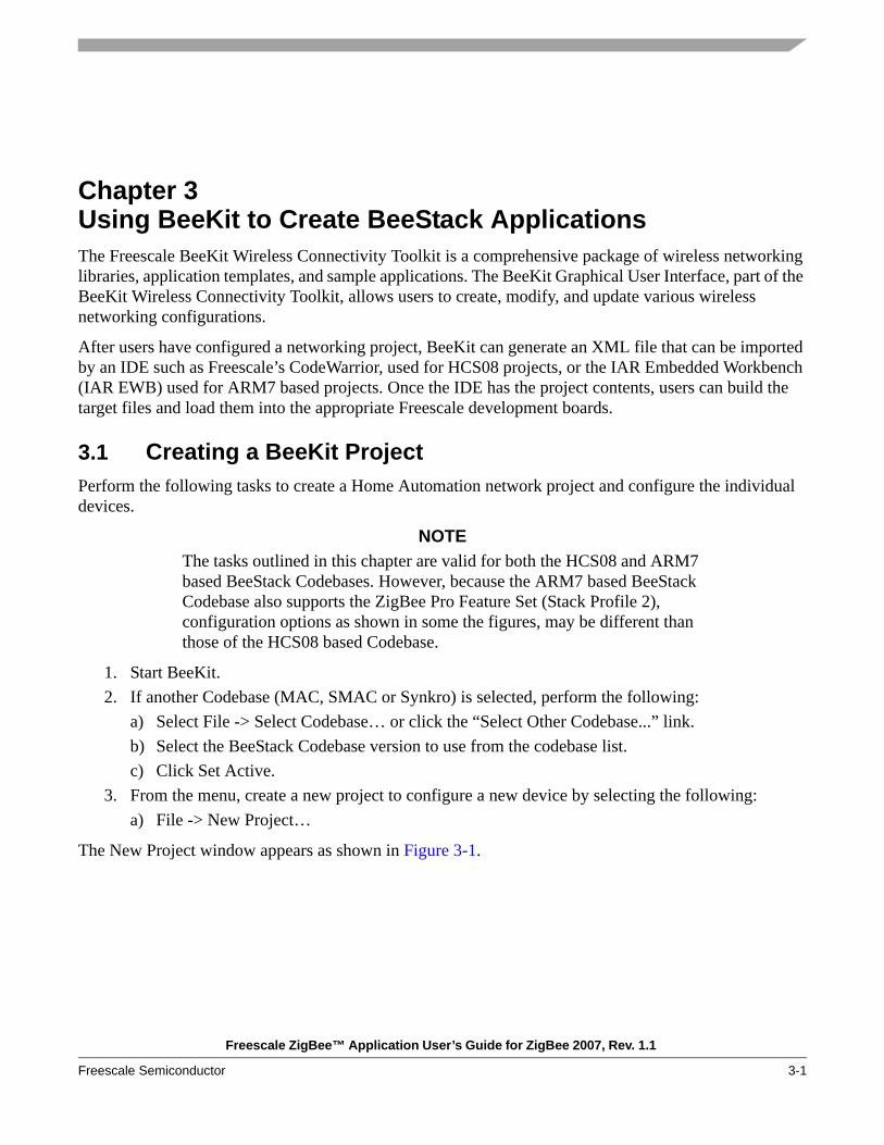
Chapter 3 Using BeeKit to Create BeeStack ApplicationsThe Freescale BeeKit Wireless Connectivity Toolkit is a comprehensive package of wireless networking libraries, application templates, and sample applications. The BeeKit Graphical User Interface, part of the BeeKit Wireless Connectivity Toolkit, allows users to create, modify, and update various wireless networking configurations.
After users have configured a networking project, BeeKit can generate an XML file that can be imported by an IDE such as Freescale’s CodeWarrior, used for HCS08 projects, or the IAR Embedded Workbench (IAR EWB) used for ARM7 based projects. Once the IDE has the project contents, users can build the target files and load them into the appropriate Freescale development boards.
3.1 Creating a BeeKit ProjectPerform the following tasks to create a Home Automation network project and configure the individual devices.
NOTEThe tasks outlined in this chapter are valid for both the HCS08 and ARM7 based BeeStack Codebases. However, because the ARM7 based BeeStack Codebase also supports the ZigBee Pro Feature Set (Stack Profile 2), configuration options as shown in some the figures, may be different than those of the HCS08 based Codebase.
1. Start BeeKit.2. If another Codebase (MAC, SMAC or Synkro) is selected, perform the following:
a) Select File -> Select Codebase… or click the “Select Other Codebase...” link.b) Select the BeeStack Codebase version to use from the codebase list.c) Click Set Active.
3. From the menu, create a new project to configure a new device by selecting the following:a) File -> New Project…
The New Project window appears as shown in Figure 3-1.

Using BeeKit to Create BeeStack Applications
Freescale ZigBee™ Application User’s Guide for ZigBee 2007, Rev. 1.1
3-2 Freescale Semiconductor
Figure 3-1. BeeKit New Project Window
4. Select the ZigBee Home Automation Applications project type from the left side of the window.

Using BeeKit to Create BeeStack Applications
Freescale ZigBee™ Application User’s Guide for ZigBee 2007, Rev. 1.1
Freescale Semiconductor 3-3
5. As shown in Figure 3-2, select the HaOnOffLight template.For the small network being built in this guide, fill in the text boxes for the template application as follows:
Project Name: ZcHaOnOffLight Solution Name: HaLightingSolution Location: BeeKitSolutions (sub directory on host PC)
Figure 3-2. Project/Template Select
6. Click the OK button to create the project for the first device.

Using BeeKit to Create BeeStack Applications
Freescale ZigBee™ Application User’s Guide for ZigBee 2007, Rev. 1.1
3-4 Freescale Semiconductor
3.1.1 Basic OptionsAfter the New Project window closes, the BeeKit Project Wizard Welcome window opens as shown in Figure 3-3.
Figure 3-3. BeeKit Project Wizard Welcome Page
Review the current project settings. In this example, the board is a MC1322x Sensor Node, the ZigBee node type is coordinator, and there is no security or mesh routing enabled. The selected stack profile is Stack profile 1 which is the default setting for HCS08 BeeStack codebase (The default settings depend on codebase platform and the project type).
There are four ways to proceed from the Wizard welcome window. • If users accept all of these settings, they can select Finish now without any more configuration• If users know the settings they want to change, they can go directly to them and select them from
the choices on the left• If users do not know what choices are available, they can click on the Next button. This is the
choice described in Section 3.1.2, “Custom Configuration Options”• If users wish to discard the modification they have made to the default configuration and close the
wizard, they can click the Set Defaults button.

Using BeeKit to Create BeeStack Applications
Freescale ZigBee™ Application User’s Guide for ZigBee 2007, Rev. 1.1
Freescale Semiconductor 3-5
3.1.2 Custom Configuration OptionsUsers can modify the device configurations by clicking on the Next button in the Welcome window. The Hardware Target selection page appears as shown in Figure 3-4 (ARM7 codebase version) and Figure 3-5 (HCS08 codebase version).
Figure 3-4. Hardware Target Page for ARM7 BeeStack Codebase
Figure 3-5. Hardware Target Page for HCS08 BeeStack Codebase

Using BeeKit to Create BeeStack Applications
Freescale ZigBee™ Application User’s Guide for ZigBee 2007, Rev. 1.1
3-6 Freescale Semiconductor
1. Change the device to a specific platform. This example uses the MC1322x Sensor Node for ARM7 codebases and the MC1321x-SRB for the HCS08 codebases.
2. Select the MC1322x Sensor Node or MC1321x-SRB radio button and click on the Next button. The Platform Modules page appears as shown in Figure 3-6.
3.
Figure 3-6. Platform Modules Page
4. Leave the default platform modules settings unchanged. LEDs and Keyboard modules on the board will be enabled. Click Next to go to the UART Parameters page shown in Figure 3-7.
5.
Figure 3-7. UART Parameters Page

Using BeeKit to Create BeeStack Applications
Freescale ZigBee™ Application User’s Guide for ZigBee 2007, Rev. 1.1
Freescale Semiconductor 3-7
6. Leave the default UART settings as is. The UART module will be enabled on the USB port of the board and ZTC will be disabled. Click Next to go to the ZigBee Device Type Selection wizard page shown in Figure 3-8.
Figure 3-8. ZigBee Device Type Selection Page
7. Make sure the Coordinator is selected as Device type.
NOTEEach network requires only one coordinator. When repeating these steps for additional devices select the correct Device type (End Device) being configured.
8. Click the Next button. The BeeStack Network Type page appears as shown in Figure 3-9 (ARM7 codebase version) and Figure 3-10 (HCS08 codebase version).
Using BeeKit to Create BeeStack Applications
Freescale ZigBee™ Application User’s Guide for ZigBee 2007, Rev. 1.1
3-8 Freescale Semiconductor
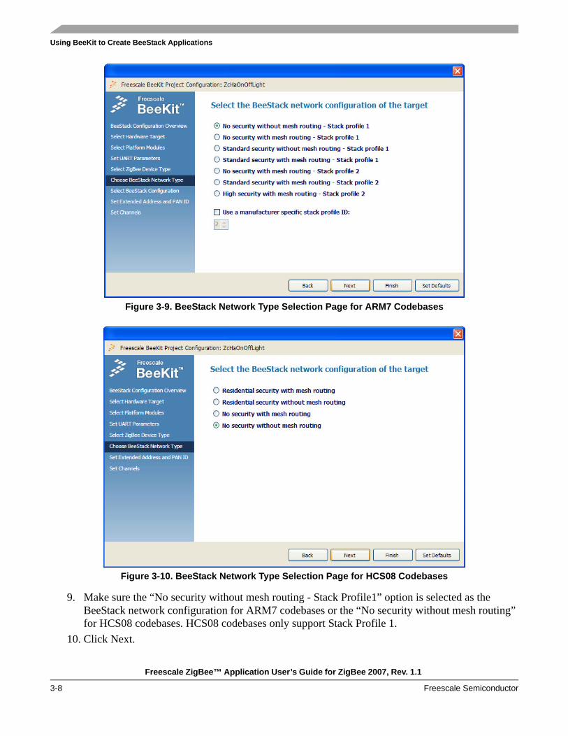
Figure 3-9. BeeStack Network Type Selection Page for ARM7 Codebases
Figure 3-10. BeeStack Network Type Selection Page for HCS08 Codebases
9. Make sure the “No security without mesh routing - Stack Profile1” option is selected as the BeeStack network configuration for ARM7 codebases or the “No security without mesh routing” for HCS08 codebases. HCS08 codebases only support Stack Profile 1.
10. Click Next.

Using BeeKit to Create BeeStack Applications
Freescale ZigBee™ Application User’s Guide for ZigBee 2007, Rev. 1.1
Freescale Semiconductor 3-9
11. If using an ARM7 codebase, the window as shown in Figure 3-11 displays additional BeeStack configuration options.
12. Click Next to keep these default options and move to the next window.13.
Figure 3-11. BeeStack Configuration Parameters for ARM7 Codebases
14. The Extended address and PAN ID page appears as shown in Figure 3-12.
Figure 3-12. Extended Address and PAN ID Selection Page

Using BeeKit to Create BeeStack Applications
Freescale ZigBee™ Application User’s Guide for ZigBee 2007, Rev. 1.1
3-10 Freescale Semiconductor
15. For this example, leave the Extended Address option with all zeros. BeeStack automatically generates a random (but not guaranteed unique) address. Alternatively, enter the full MAC address from the label on the development board. Also leave the default PAN ID set to 0x1AAA.
16. Click Next. The Channels page appears as shown in Figure 3-13.
Figure 3-13. Channels Page
WARNINGThe channel and PAN ID must be the same for all devices on the network. If users set the channel to something other than the default, verify in the setup for subsequent devices that the channel is the same one selected for this initial device. If users select a PAN ID, a colleague might assign the same value to another PAN later. Expect odd behavior. If users choose 0xFFFF for their PAN ID, the coordinator selects one when it forms its network. The nodes that join this network must be able to identify the correct network by some method that does not involve a known PAN ID. This is not a BeeStack issue; this is a real-world ZigBee issue. User products must be able to cope with this.
17. Click on the Finish button.
The setup concludes when BeeKit returns to the main Project window.

Using BeeKit to Create BeeStack Applications
Freescale ZigBee™ Application User’s Guide for ZigBee 2007, Rev. 1.1
Freescale Semiconductor 3-11
3.1.3 Creating Additional DevicesTo set up a ZigBee wireless network, the coordinator needs other devices to communicate with and control. Create additional devices by performing the following steps:
1. From the main menu, Select Solution -> Add Project…2. This opens the Add Project window. 3. Select ZigBee Home Automation Applications the same as was done for the coordinator. This time,
select the HA OnOffSwitch.4. Repeat the steps as described in Section 3.1.1, “Basic Options” and Section 3.1.2, “Custom
Configuration Options”. Adjust the settings to suit the application. Note that the current settings for the switch are different than the light.
5. After selecting Finish for the switch application, the BeeKit main window appears as shown in Figure 3-14.
Figure 3-14. BeeKit Main Window
When users click on a component in the Solution Explorer area, useful information about that item appears under the Property List tab. Users can also change their settings there. For example,
• To change the development board:— Select the Platform component in the Explorer window— Select the Hardware Target property in the Property List— Use the pull-down menu to select the board
• To change the device type:— Select the MacPhy component in the Explorer window

Using BeeKit to Create BeeStack Applications
Freescale ZigBee™ Application User’s Guide for ZigBee 2007, Rev. 1.1
3-12 Freescale Semiconductor
— Select the Device Type property in the Property List— Use the pull-down menu to select coordinator, router, or end device
• To change the BeeStack default configuration regarding routing and security:— Select the BeeStack component in the Explorer window— Select the Stack Library Configuration in the Property List— For HCS08 BeeStack codebases use the pull-down menu to select the configuration — For ARM7 BeeStack codebases use the BeeStack Configuration Editor by clicking on the [...]
button on the right of the property and use the options in the Editor window to change configuration
3.1.4 Exporting Created BeeKit ProjectsOnce all the devices to be used in the network have been created as BeeKit Projects and saved as a BeeKit Solution, the files must be exported into a format for importing into either the IAR Embedded Workbench or CodeWarrior IDE used for compiling and debugging.
To export the saved solution:1. From the Solution menu, select Export Solution. BeeKit verifies the internal consistency of the
configuration, looking for such errors as two endpoints with the same number. If the verification succeeds, the window that opens will display all the created devices, each with a checked box as shown in Figure 3-15.
Figure 3-15. Export BeeKit Project Solution Window
2. Click on the OK button to start the export process. While BeeKit executes this, it displays the window shown in Figure 3-16, and the steps it takes scroll by in the Messages window pane.

Using BeeKit to Create BeeStack Applications
Freescale ZigBee™ Application User’s Guide for ZigBee 2007, Rev. 1.1
Freescale Semiconductor 3-13
Figure 3-16. Please Wait – Exporting Project Window
3. When BeeKit finishes exporting, the Wait window disappears. The Messages window still contains the export steps, which can be scrolled through. The export process is now complete.
4. Exit BeeKit by choosing File -> Exit from the menu bar.
3.2 Automatically Importing Projects into an IDE The project files created in BeeKit and saved as Solutions must be imported into CodeWarrior or Embedded Workbench to build the binary output file suitable for programming into each MCU’s FLASH.
To export and import the solution into the appropriate IDE automatically perform the appropriate task depending on the IDE being used:
From the BeeKit tool bar, click on Solution -> Export -> Open Solution in IAR EWBOrFrom the BeeKit tool bar, click on Solution -> Export -> Open Solution in CodeWarrior.OrClick the IDE icon in the toolbar as shown in Figure 3-17 and export the solution in IAR EWB..
Figure 3-17. Exporting and Opening the Solution in Embedded Workbench

Using BeeKit to Create BeeStack Applications
Freescale ZigBee™ Application User’s Guide for ZigBee 2007, Rev. 1.1
3-14 Freescale Semiconductor
BeeKit exports the solution as shown in Section 3.1, “Creating a BeeKit Project”, automatically opens the IDE and loads the selected projects that were exported. Figure 3-18 shows the projects of the solution previously created and imported into the IAR EWB.
Figure 3-18. Solution Projects Imported in IAR Embedded Workbench
3.3 Manually Importing Projects into an IDEWhen BeeKit exports the projects of a solution it creates a *.xml file in the exported project folder that can be used to manually import and open the projects in the corresponding IDE (IAR Embedded Workbench or CodeWarrior).
To open the projects manually in IAR Embedded Workbench go to the exported project folder and launch the *.eww workspace file created during solution export.
To open the projects manually in CodeWarrior, follow these steps:1. Start CodeWarrior, which opens to a blank window with the menu at the top.2. Select File -> Import Project… as shown in Figure 3-19.

Using BeeKit to Create BeeStack Applications
Freescale ZigBee™ Application User’s Guide for ZigBee 2007, Rev. 1.1
Freescale Semiconductor 3-15
Figure 3-19. CodeWarrior Import Project…
3. Navigate to the directory created in the BeeKit export procedure. In this example, it is:
C:\BeeKitSolutions\HaLightingSolution
4. This directory contains a directory for each device created earlier in BeeKit. This example uses the directories ZcSrbHaOnOffLight and ZedSrbHaOnOffSwitch. Users will need to import each device project separately.
5. Navigate into the ZcSrbHAOnOffLight directory as shown in Figure 3-20.
Figure 3-20. CodeWarrior Open XML Window
6. Click on the BeeKit .xml file to be imported and select Open. The Open window is replaced by a Save window in the same directory. Type in the name for the CodeWarrior project file without an extension. This example uses the same name as the .xml file as shown in Figure 3-21. Click the Save button.

Using BeeKit to Create BeeStack Applications
Freescale ZigBee™ Application User’s Guide for ZigBee 2007, Rev. 1.1
3-16 Freescale Semiconductor
Figure 3-21. CodeWarrior Name New Project Window
7. CodeWarrior creates and loads the project file as shown in Figure 3-22.
Figure 3-22. CodeWarrior ZcSrbHaOnOffLight Project Window

Using BeeKit to Create BeeStack Applications
Freescale ZigBee™ Application User’s Guide for ZigBee 2007, Rev. 1.1
Freescale Semiconductor 3-17
3.4 Building a Code Image Using the IDEs
3.4.1 Building a Code Image Using Embedded WorkbenchTo build the application binary in IAR Embedded Workbench:
1. In the Workspace panel, select the Overview tab.2. Right click on the project to build. 3. Select “Set as Active” from the menu.4. Build the binary in one of three ways:
a) Press the Make hot key F7b) Click the “Make” iconc) From the menu select Project -> Make
Embedded Workbench reports the build progress in the Build Messages panel as shown in Figure 3-23.
Figure 3-23. IAR EWB Showing the Build Messages Panel
Using BeeKit to Create BeeStack Applications
Freescale ZigBee™ Application User’s Guide for ZigBee 2007, Rev. 1.1
3-18 Freescale Semiconductor
3.4.2 Building a Code Image Using CodeWarriorBuild the application binary in CodeWarrior in one of three ways:
1. Press the Make hot key F72. Click the “Make” icon (Looks like paper with a pen in hand.)3. From the menu select Project -> Make
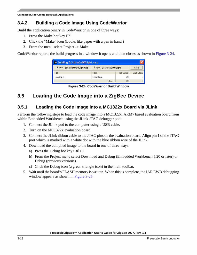
CodeWarrior reports the build progress in a window it opens and then closes as shown in Figure 3-24.
Figure 3-24. CodeWarrior Build Window
3.5 Loading the Code Image into a ZigBee Device
3.5.1 Loading the Code Image into a MC1322x Board via JLinkPerform the following steps to load the code image into a MC1322x, ARM7 based evaluation board from within Embedded Workbench using the JLink JTAG debugger pod.
1. Connect the JLink pod to the computer using a USB cable.2. Turn on the MC1322x evaluation board.3. Connect the JLink ribbon cable to the JTAG pins on the evaluation board. Align pin 1 of the JTAG
port which is marked with a white dot with the blue ribbon wire of the JLink.4. Download the compiled image to the board in one of three ways:
a) Press the Debug hot key Ctrl+D.b) From the Project menu select Download and Debug (Embedded Workbench 5.20 or later) or
Debug (previous versions).c) Click the Debug icon (a green triangle icon) in the main toolbar.
5. Wait until the board’s FLASH memory is written. When this is complete, the IAR EWB debugging window appears as shown in Figure 3-25.

Using BeeKit to Create BeeStack Applications
Freescale ZigBee™ Application User’s Guide for ZigBee 2007, Rev. 1.1
Freescale Semiconductor 3-19
6.
Figure 3-25. IAR EWB Debugging Window
7. Stop the debugger by pressing Ctrl+Shift+D or by choosing “Stop Debugging” from the Debug menu.
8. Right click on the HaOnOffSwitch application in the Workspace Overview panel and select “Set as Active” from the context menu.
9. Repeat the steps as shown in Section 3.5.1, “Loading the Code Image into a MC1322x Board via JLink” to load the code for the other application into another board.
3.5.2 Loading the Code Image into a HCS08 Board via P&E BDMTo load the code image into a MC1321x/MC1320x/MC1319x HCS08 based evaluation board using the P&E BDM pod perform the following steps:
1. Connect the P&E BDM pod to the host computer using the USB cable. A lighted blue LED indicates the BDM has power and a successful USB connection.
2. Connect the BDM pod to the device. Align pin 1 of the BDM port connector with the red wire of the flat cable connector— MC1319x-EVB, MC1319x-SARD, and MC1321x-SRB: The connector is J101, and pin 1 is
marked with a ‘1’— MC1321x-NCB: The connector is marked “BDM”, and pin 1 has a white dot beside it— 1320x-QE128EVB: The connector is labeled J9, and pin 1 is the one next to the label
3. Turn on the board.

Using BeeKit to Create BeeStack Applications
Freescale ZigBee™ Application User’s Guide for ZigBee 2007, Rev. 1.1
3-20 Freescale Semiconductor
4. The amber LED on the BDM will now light up, and the LED on the development board will also light up. If not, switch the power off and on again on the board. Recheck the connection to the BDM port. Check the power adapter connection to the board or verify that the batteries are charged.
5. Download the compiled image to the board by choosing one of three waysa) Press the Debug hot key F5b) Click the “Debug” icon (Looks like a bug with a green triangle.)c) From the menu select Project -> Debug
CodeWarrior opens the Debug window as shown in Figure 3-26.
Figure 3-26. CodeWarrior Debugger Window

Using BeeKit to Create BeeStack Applications
Freescale ZigBee™ Application User’s Guide for ZigBee 2007, Rev. 1.1
Freescale Semiconductor 3-21
CodeWarrior then opens the connection manager window, if this is the first programming/debug event since it was opened, as shown in Figure 3-27.
Figure 3-27. CodeWarrior Connection Manager Window
6. Click on the Connect button. The programmer window displays the running status in a window as shown in Figure 3-28 and then closes automatically.
Figure 3-28. Status Window for Connection Manager

Using BeeKit to Create BeeStack Applications
Freescale ZigBee™ Application User’s Guide for ZigBee 2007, Rev. 1.1
3-22 Freescale Semiconductor
NOTEIf the Status window does not display the line “programming and verifying Address,” either the BDM or USB cables are not properly connected. Correct the problem before repeating the step.
7. Close the debugger by selecting File -> Exit.
WARNINGExit the debug mode to avoid multiple debug appearances; having multiple appearances while setting up boards can produce unexpected results.
8. Disconnect the board and exit the CodeWarrior project, leaving CodeWarrior running.9. Power cycle the board or press the reset button to get the board ready for use.10. Repeat these steps to put the ZedSrbHaOnOffSwitch code into another board.

Freescale ZigBee™ Application User’s Guide for ZigBee 2007, Rev. 1.1
Freescale Semiconductor 4-1
Chapter 4 Starting and Running a Simple ZigBee NetworkThis chapter goes through the steps to establish a small Home Automation network using the two nodes programmed in the previous chapters. The network consists of the HA OnOffLight and the HA OnOffSwitch.
NOTEReferring to switches SW1-SW4 in this chapter refers to the four push-buttons present on most of the Freescale development boards. For example, on the 1320x-QE128EVB, the four buttons are actually labeled SW2-SW5 and on the SARD they are labeled S101-S104.
If using the MC1322x-LPN board, only two buttons and two leds are available. Restrictions and changes related to this board are mentioned in the corresponding steps if needed. See Section 2.1.1, “HCS08 MCU Board Details” for more information.
4.1 Starting the Network1. Turn on the power for the OnOffLight.
LED1 will flash to indicate that the board is not on a network (if a ZR or ZED) or that a network has not been formed (ZC).
2. Press SW4 to select a channel other than the one selected in BeeKit (optional - not available if a MC1322x-LPN board is used for one of the nodes).With each key press, the four LEDs will light up briefly to indicate the channels from 11 to 26. The LEDs display the offset from channel 11 in binary: 0000 is channel 11, and 1111 is channel 26.
3. Repeat steps 1 and 2 for the OnOffSwitch. The network will not form if the two nodes are on different channels after step 2, because the example applications are configured to look on only one channel for a network.
Start the network with the following steps:1. Press SW1 on the OnOffLight, which is configured as the ZC.
The LEDs 1-4 will light up in sequence and then go out until only LED1 remains lighted. This is the first step in creating a small network, since this step serves to form the network.
2. Press SW1 on the OnOffSwitch, which is configured as the ZED. All the LEDs on this board will flash in a series, and finally only LED1 will light to indicate that ZED has joined the network that the OnOffLight has formed.
3. Press SW3 first on one board, then within ten seconds, press SW3 on the other board, to bind the devices.
Starting and Running a Simple ZigBee Network
Freescale ZigBee™ Application User’s Guide for ZigBee 2007, Rev. 1.1
4-2 Freescale Semiconductor
LED3 starts flashing, then goes solid when binding completes. If LED3 flashes, but then goes out (unlighted), binding failed. Turn off the boards and try again. If using the MC1322x-LPN board, press SW2 instead of SW3 and monitor LED2 instead of LED3.
4. Long press SW1 to go into run mode on both boards. Holding a switch down for more than one second is a long press.
4.2 Running the Network: Remotely Controlling a Light1. Press SW1 on the board defined as the ZED (OnOffSwitch) to toggle the light.2. LED2 on the ZC (OnOffLight) changes state: it turns on.3. Press SW1 on the ZED again to toggle the light. 4. LED2 on the ZC changes state again: it turns off. 5. SW1 on the ZC can also toggle the light. Press it and ZC’s LED2 changes state6. Press SW1 on the ZED again to toggle the light again.
This completes setting up and using a small Home Automation Lighting Control network. For additional example applications, see Chapter 5, “Creating a Wireless UART Application”.

Freescale ZigBee™ Application User’s Guide for ZigBee 2007, Rev. 1.1
Freescale Semiconductor 5-1
Chapter 5 Creating a Wireless UART ApplicationThis chapter shows how to create a Freescale Wireless UART application using the Freescale BeeKit Wireless Connectivity Toolkit. The Freescale Wireless UART application is not part of the ZigBee Alliance Home Automation (HA) profile and is not part of any other ZigBee public profiles. The Wireless UART application is considered by the ZigBee Alliance (www.zigbee.org) as a “Manufacturer Specific” profile, in that these applications are only meant to function with devices from a single manufacturer.
The Wireless UART runs in a fully buffered interrupt driven mode and is well suited for large file transfers. However, the example used in this chapter only sends a small amount of text to show Wireless UART basic functionality.
The following scenario is based on using a HCS08 BeeStack codebase. Exceptions are noted where there are differences when using an ARM7 BeeStack codebase.
5.1 Creating the Wireless UART BeeKit ProjectFollow these steps to create a BeeKit project and configure the Coordinator and Router devices.
1. Start the BeeKit Wireless Connectivity Toolkit. 2. If another Codebase (MAC, SMAC or Synkro) is selected, perform the following:
a) From the tool bar select File -> Select Codebase… or click the “Select Other Codebase...” button.
b) From the Codebase list, select a BeeStack Codebase version.c) Click the Set Active button.
3. From the menu, create a new project to configure a new device by selecting File -> New Project… The New Project window appears as shown in Figure 5-1.

Creating a Wireless UART Application
Freescale ZigBee™ Application User’s Guide for ZigBee 2007, Rev. 1.1
5-2 Freescale Semiconductor
Figure 5-1. BeeKit New Project Window
4. If using the HCS08 codebase, select the ZigBee Home Automation Applications project type from the left side of the window. If using an ARM7 codebase select the Other ZigBee Applications project type instead.
5. As shown in Figure 5-2, select the Wireless UART template.6. For the small network being built in this guide, fill in the text boxes for the template application as
follows: Project name: ZcSrbWirelessUARTSolution Name: WirelessUART SolutionLocation: c:\WirelessUART (or other sub directory on host PC)
Creating a Wireless UART Application
Freescale ZigBee™ Application User’s Guide for ZigBee 2007, Rev. 1.1
Freescale Semiconductor 5-3
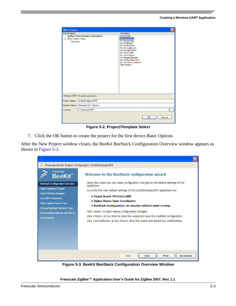
Figure 5-2. Project/Template Select
7. Click the OK button to create the project for the first device.Basic Options
After the New Project window closes, the BeeKit BeeStack Configuration Overview window appears as shown in Figure 5-3.
Figure 5-3. BeeKit BeeStack Configuration Overview Window
Creating a Wireless UART Application
Freescale ZigBee™ Application User’s Guide for ZigBee 2007, Rev. 1.1
5-4 Freescale Semiconductor
There are three ways to proceed from this window.
Review the current project settings. In this example, the board is a MC1321x-SRB, the ZigBee node type is coordinator, and there is no security or mesh routing enabled. (The default settings depend on the project type.)
• If users accept all of these settings, they can select Finish now without any more configuration• If users know the settings they want to change, they can go directly to them and select them from
the choices on the left• If users do not know what choices are available, they can click on the Next button. This option is
described in Section 5.1.1, “Custom Configuration Options”
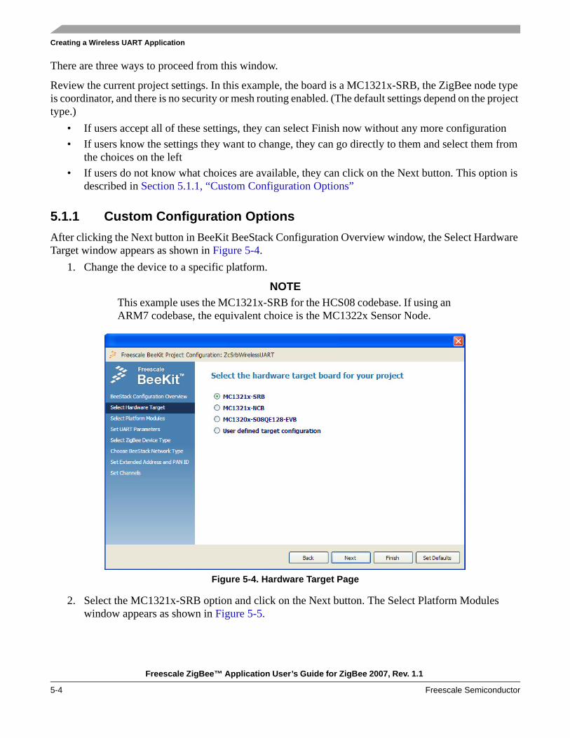
5.1.1 Custom Configuration OptionsAfter clicking the Next button in BeeKit BeeStack Configuration Overview window, the Select Hardware Target window appears as shown in Figure 5-4.
1. Change the device to a specific platform.
NOTEThis example uses the MC1321x-SRB for the HCS08 codebase. If using an ARM7 codebase, the equivalent choice is the MC1322x Sensor Node.
Figure 5-4. Hardware Target Page
2. Select the MC1321x-SRB option and click on the Next button. The Select Platform Modules window appears as shown in Figure 5-5.

Creating a Wireless UART Application
Freescale ZigBee™ Application User’s Guide for ZigBee 2007, Rev. 1.1
Freescale Semiconductor 5-5
3.
Figure 5-5. Platform Modules Page
4. Leave the default platform modules settings unchanged. (LEDs and Keyboard modules on the SRB board enabled.) Click the Next button and the Set UART Parameters window appears as shown in Figure 5-6. Leave the default UART settings unchanged. (The UART module enabled on the USB port of the SRB and the ZigBee Test Client (ZTC) disabled.)
5.
Figure 5-6. UART Parameters Page

Creating a Wireless UART Application
Freescale ZigBee™ Application User’s Guide for ZigBee 2007, Rev. 1.1
5-6 Freescale Semiconductor
6. Click the Next button and the Select ZigBee Device Type window appears as shown in Figure 5-7. Ensure that the “Coordinator” option is selected.
Figure 5-7. ZigBee Device Type Selection Page for Coordinator Device
7. Click the Next button and the Choose BeeStack Network Type window appears as shown in Figure 5-8. Select the “No security without mesh routing” option.
Figure 5-8. BeeStack Network Type Selection Page
Creating a Wireless UART Application
Freescale ZigBee™ Application User’s Guide for ZigBee 2007, Rev. 1.1
Freescale Semiconductor 5-7
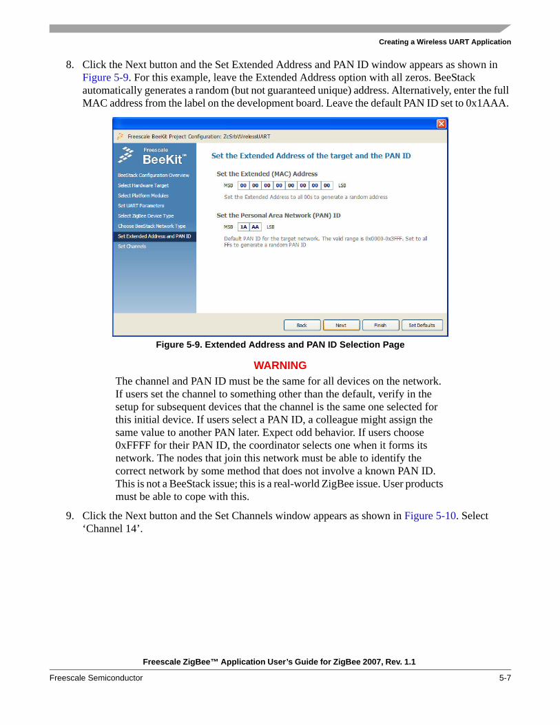
8. Click the Next button and the Set Extended Address and PAN ID window appears as shown in Figure 5-9. For this example, leave the Extended Address option with all zeros. BeeStack automatically generates a random (but not guaranteed unique) address. Alternatively, enter the full MAC address from the label on the development board. Leave the default PAN ID set to 0x1AAA.
Figure 5-9. Extended Address and PAN ID Selection Page
WARNINGThe channel and PAN ID must be the same for all devices on the network. If users set the channel to something other than the default, verify in the setup for subsequent devices that the channel is the same one selected for this initial device. If users select a PAN ID, a colleague might assign the same value to another PAN later. Expect odd behavior. If users choose 0xFFFF for their PAN ID, the coordinator selects one when it forms its network. The nodes that join this network must be able to identify the correct network by some method that does not involve a known PAN ID. This is not a BeeStack issue; this is a real-world ZigBee issue. User products must be able to cope with this.
9. Click the Next button and the Set Channels window appears as shown in Figure 5-10. Select ‘Channel 14’.

Creating a Wireless UART Application
Freescale ZigBee™ Application User’s Guide for ZigBee 2007, Rev. 1.1
5-8 Freescale Semiconductor
Figure 5-10. Channels Page
10. Click the Finish button.
5.1.2 Adding a Project for the RouterNow that the coordinator is added, users need to add a project for the Router. To add a project for the Router using BeeKit, perform the following tasks.
1. From the BeeKit main window, select Solutions -> Add Project. The Add Project window appears as shown in Figure 5-11.
Figure 5-11. Add New Project Page

Creating a Wireless UART Application
Freescale ZigBee™ Application User’s Guide for ZigBee 2007, Rev. 1.1
Freescale Semiconductor 5-9
2. Select “WirelessUART” and name the project ZrSrbWirelessUART as shown in Figure 5-11.3. Continue clicking the Next button until reaching the “Select ZigBee Device Type” window as
shown in Figure 5-12. Select the “Router” option and click on the Next button.
Figure 5-12. Selecting “Router” as the Device Type
4. Click the Next button and the Choose BeeStack Network Type window appears. Select the same network type using the same settings used for the Coordinator as shown in Figure 5-8. (No security without mesh routing).
5. Click the Next button and set the Extended address and PAN ID the same as it was for the Coordinator as shown in Figure 5-9.
6. Click the Next button and select the same channel as the Coordinator as shown in Figure 5-10.7. Click on the Finish button.

Creating a Wireless UART Application
Freescale ZigBee™ Application User’s Guide for ZigBee 2007, Rev. 1.1
5-10 Freescale Semiconductor
This completes the steps needed to create a solution/project for the Wireless UART application for a Coordinator and a Router. The solution is now ready for export for use in CodeWarrior. The BeeKit main window should appear as shown in Figure 5-13.
Figure 5-13. Main Wireless UART Project Page
5.1.3 Exporting the BeeKit Projects to an IDEAfter the solution has been created it needs to exported to an IDE (CodeWarrior or Embedded Workbench) in order to be built and loaded on evaluation boards. To export the solution to an IDE perform the following tasks:
1. From the BeeKit main window menu bar, choose Solution -> Export and Open Solution in CodeWarrior/Embedded Workbench. Before exporting, BeeKit verifies the internal consistency of the configuration and looks for errors such as two endpoints with the same number. If verification succeeds, the window that appears displays the created solution and the IDE that will be used for building as shown in Figure 5-14.
Figure 5-14. Export BeeKit Project Solution Window

Creating a Wireless UART Application
Freescale ZigBee™ Application User’s Guide for ZigBee 2007, Rev. 1.1
Freescale Semiconductor 5-11
2. Click on the OK button to start the export process. BeeKit displays the steps it takes during the export process in the Messages display area of the BeeKit main window.
3. When BeeKit completes the export, it launches the IDE and imports the projects in a new workspace. Figure 5-15 shows the projects imported in CodeWarrior.
4.
Figure 5-15. Projects Imported in CodeWarrior
Figure 5-16 shows the projects imported in Embedded Workbench.
Figure 5-16. Projects Imported in Embedded Workbench
The export process is now complete.
Creating a Wireless UART Application
Freescale ZigBee™ Application User’s Guide for ZigBee 2007, Rev. 1.1
5-12 Freescale Semiconductor
5. Exit BeeKit by choosing File -> Exit from the tool bar.
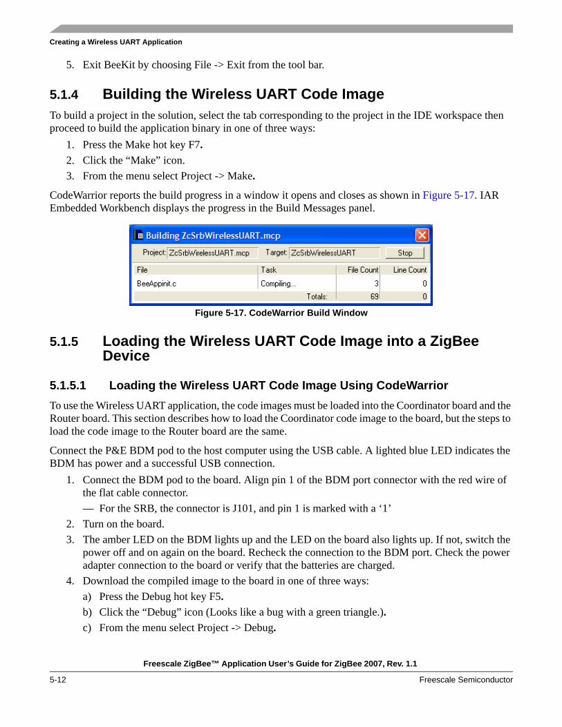
5.1.4 Building the Wireless UART Code Image To build a project in the solution, select the tab corresponding to the project in the IDE workspace then proceed to build the application binary in one of three ways:
1. Press the Make hot key F7.2. Click the “Make” icon.3. From the menu select Project -> Make.
CodeWarrior reports the build progress in a window it opens and closes as shown in Figure 5-17. IAR Embedded Workbench displays the progress in the Build Messages panel.
Figure 5-17. CodeWarrior Build Window
5.1.5 Loading the Wireless UART Code Image into a ZigBee Device
5.1.5.1 Loading the Wireless UART Code Image Using CodeWarriorTo use the Wireless UART application, the code images must be loaded into the Coordinator board and the Router board. This section describes how to load the Coordinator code image to the board, but the steps to load the code image to the Router board are the same.
Connect the P&E BDM pod to the host computer using the USB cable. A lighted blue LED indicates the BDM has power and a successful USB connection.
1. Connect the BDM pod to the board. Align pin 1 of the BDM port connector with the red wire of the flat cable connector.— For the SRB, the connector is J101, and pin 1 is marked with a ‘1’
2. Turn on the board.3. The amber LED on the BDM lights up and the LED on the board also lights up. If not, switch the
power off and on again on the board. Recheck the connection to the BDM port. Check the power adapter connection to the board or verify that the batteries are charged.
4. Download the compiled image to the board in one of three ways:a) Press the Debug hot key F5.b) Click the “Debug” icon (Looks like a bug with a green triangle.).c) From the menu select Project -> Debug.
Creating a Wireless UART Application
Freescale ZigBee™ Application User’s Guide for ZigBee 2007, Rev. 1.1
Freescale Semiconductor 5-13
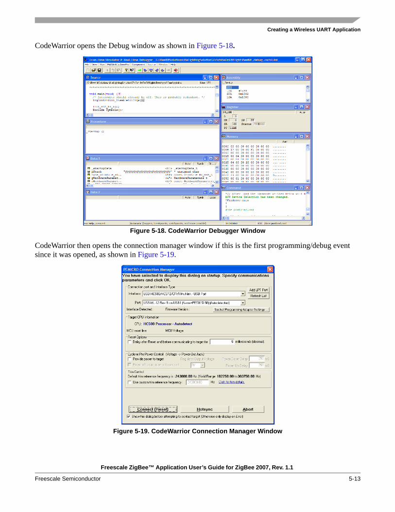
CodeWarrior opens the Debug window as shown in Figure 5-18.
Figure 5-18. CodeWarrior Debugger Window
CodeWarrior then opens the connection manager window if this is the first programming/debug event since it was opened, as shown in Figure 5-19.
Figure 5-19. CodeWarrior Connection Manager Window

Creating a Wireless UART Application
Freescale ZigBee™ Application User’s Guide for ZigBee 2007, Rev. 1.1
5-14 Freescale Semiconductor
5. Click on the Connect button. The programmer window displays the running status in a window as shown in Figure 5-20 and then automatically closes this window.
Figure 5-20. Status Window for Connection Manager
NOTEIf the Status window does not display the line “programming and verifying Address,” either the BDM or USB cables are not properly connected. Correct the problem before repeating the step.
6. Close the debugger by selecting File -> Exit.
WARNINGExit the debug mode to avoid multiple debug appearances; having multiple appearances while setting up boards can produce unexpected results.
7. Disconnect the board and exit the CodeWarrior project, leaving CodeWarrior running.8. Power cycle the board or press the reset button to get the board ready for use.9. This concludes the steps needed to load the code image for the Coordinator.10. Go to Step 1 and repeat the steps to load the code image to the Router board.
5.1.5.2 Loading the Wireless UART Code Image Using IAR EWBTo load the code image into a MC1322x evaluation board from within Embedded Workbench using the JLink JTAG debugger pod perform the following steps.
1. Select the Coordinator (ZcSrbWirelessUART) project tab in the Workspace panel.2. Connect the JLink pod to the computer using a USB cable.3. Turn on the MC1322x Sensor Node board.4. Connect the JLink ribbon cable to the JTAG pins on the evaluation board. Align pin 1 of the JTAG
port which is marked with a white dot with the blue ribbon wire of the JLink.5. Download the compiled image to the board by choosing one of three ways:
a) Press the Debug hot key Ctrl+D.

Creating a Wireless UART Application
Freescale ZigBee™ Application User’s Guide for ZigBee 2007, Rev. 1.1
Freescale Semiconductor 5-15
b) From the Project menu select Download and Debug (Embedded Workbench 5.20 or later) or Debug (previous versions).
c) Click the green triangle icon in the main toolbar.6. Wait while the flash of the board is written. When this is complete, the debugging view of
Embedded Workbench will launch as shown in Figure 5-21.
Figure 5-21. IAR Embedded Workbench Debugging View
7. Stop the debugger by pressing Ctrl+Shift+D or by choosing “Stop Debugging” from the Debug menu.
8. Select the Router (ZrSrbWirelessUART) project tab in the Workspace panel9. Repeat the Steps 3-7 to put the code for the second application into another MC1322x Sensor Node
board.

Creating a Wireless UART Application
Freescale ZigBee™ Application User’s Guide for ZigBee 2007, Rev. 1.1
5-16 Freescale Semiconductor
5.2 Wireless UART Setup and OperationThe following sections show how to identify and setup the UART/USB virtual COM ports, set up Hyperterminal, start the Wireless UART application, form the network, and use the Wireless UART application.
5.2.1 Setting up the UART/USB Virtual Com Ports1. To determine which COM ports is being used by both nodes, plug a USB cable attached to a host
PC into each device and power on the boards. 2. In the Windows Device Manager, under the Ports (COM & LPT) option, two devices labeled either
“Freescale ZigBee/802.15.4 MAC COM Device” or “USB Serial Port” appear as shown in Figure 5-22. (The COM ports shown in Figure 5-22 will be different on every PC).
Figure 5-22. COM Ports in Device Manager

Creating a Wireless UART Application
Freescale ZigBee™ Application User’s Guide for ZigBee 2007, Rev. 1.1
Freescale Semiconductor 5-17
3. Using Hyperterminal, set up a Virtual COM Port for each of the two nodes. Figure 5-23 shows the correct COM Port settings to run the Wireless UART application.
NOTE Flow control is enabled on both nodes.
Figure 5-23. Default BeeStack RS-232 Settings
Figure 5-24 show correct ASCII Setup configuration used to run the Wireless UART application.
Figure 5-24. Additional Terminal Program Settings

Creating a Wireless UART Application
Freescale ZigBee™ Application User’s Guide for ZigBee 2007, Rev. 1.1
5-18 Freescale Semiconductor
5.2.2 Starting the Wireless UART Application1. Connect both the Coordinator and Router to a host PC using USB cables.2. Open up each of the Hyperterminal programs for each virtual COM port using the Hyperterminal
settings set up in Section 5.2, “Wireless UART Setup and Operation”.3. Turn on the power for the Wireless UART Coordinator and Router.
LED1 flashes to indicate that the board is not on a network or that a network has not been formed ZigBee Coordinator (ZC).
4. As an option, on each node, press SW4 to select a channel other than the one selected in BeeKit. This is only needed if there are interference issues.With each key press, the four LEDs light up briefly to indicate the channels from 11 to 26. The LEDs display the offset from channel 11 in binary: 0000 is channel 11, and 1111 is channel 26.
NOTEThe network will not form if the two nodes are on different channels after Step 2, because the example applications are configured to look on only one channel for a network.
5.2.3 Forming and Starting the Network1. Press SW1 on the Wireless UART node that is configured as the Coordinator.
LEDs 1-4 light up in sequence and then go out until only LED1 is on. This is the first step in forming this small network.
2. Press SW1 on the Wireless UART node that is configured as the Router. All of the LEDs on this board will flash in a series, and finally only LED1 stays lit to indicate that the Router has joined the network that the Coordinator has formed.
3. To bind the devices, press SW3 first on one board, then within ten seconds, press SW3 on the other board.LED3 starts flashing, then goes solid when binding is complete. If LED3 flashes, but then goes out, the bind process failed. Turn off the boards and try again by repeating Steps 1-3 of this section.
4. On both boards, perform a long press (more than one second) of SW1 to bring both boards into run mode.

Creating a Wireless UART Application
Freescale ZigBee™ Application User’s Guide for ZigBee 2007, Rev. 1.1
Freescale Semiconductor 5-19
5.2.4 Using the Wireless UART ApplicationOnce the Wireless UART application is loaded to boards, the application is started, and the network is formed and running, the Wireless UART application is ready to use.
1. Type some text in one of the Hyperterminal windows as shown in Figure 5-25.
Figure 5-25. Text Typed in First Hyperterminal Window
2. The typed text is displayed as output in the second Hyperterminal as shown in Figure 5-26
Figure 5-26. Text Echoed in Second Hyperterminal Window

Creating a Wireless UART Application
Freescale ZigBee™ Application User’s Guide for ZigBee 2007, Rev. 1.1
5-20 Freescale Semiconductor

Freescale ZigBee™ Application User’s Guide for ZigBee 2007, Rev. 1.1
Freescale Semiconductor 6-1
Chapter 6 Creating a Smart Energy Network ApplicationThis chapter shows how to create a Smart Energy Network consisting of three different applications using the Freescale BeeKit Wireless Connectivity Toolkit. The Freescale Smart Energy applications are part of the ZigBee Alliance Smart Energy (SE) profile. While this chapter describes how to use the Smart Energy application, it does not describe the projects in great detail.
6.1 Software and Hardware RequirementsBefore performing any of the steps in this chapter, users must ensure the following:
• Chapter 3 and Chapter 4 of this guide have been read, the steps performed and understood• The Freescale Test Tool is installed and running on the PC• The Freescale Test Tool User’s Guide, Section 2.5 has been read, the steps performed and
understood• One 1322x Sensor Node board is available to be used as the Energy Service Portal (ESP)• One 1322x Sensor Node board is available to be used as the Metering Device• One 1322x Network Node is available to be used as the In Premise Display
6.2 Creating a BeeKit ProjectFollow these steps to create a BeeKit project and configure the Coordinator and Router devices.
1. Start the BeeKit Wireless Connectivity Toolkit. 2. If another Codebase (MAC or SMAC) is selected, perform the following:
a) From the tool bar, click on File -> Select Codebase… or click the “Select Other Codebase...” button.
b) From the Codebase list, choose the appropriate BeeStack Codebase version.c) Click the OK button.
3. From the menu, create a new project to configure a new device by selecting File -> New Project… The New Project window appears as shown in Figure 6-1.

Creating a Smart Energy Network Application
Freescale ZigBee™ Application User’s Guide for ZigBee 2007, Rev. 1.1
6-2 Freescale Semiconductor
Figure 6-1. New Project Window
4. Select the Smart Energy Applications project type from the left side of the window.5. Select the “Se Energy Service Portal” (ESP) template and create the project by entering the
following information into the appropriate field:Project Name: ZcEnergyServicePortalSolution Name: SE Demo Solution Location: c:\Se_demo (or other sub directory on host PC)
6. Use the default settings and only change the hardware settings if a board other than a 1322x Sensor Node or 1322x Network Node are used.
7. Add an “SE Metering Device” to the Solution from the BeeKit main window by selecting solutions -> Add Project.
8. Select the Smart Energy Applications project type from the left side of the window.9. Select the “Se metering Device” template and create the project by entering the following
information into the appropriate field: Project Name: ZedMeteringDeviceSolution Name: SE Demo Solution Location: c:\Se_demo (or other sub directory on host PC)

Creating a Smart Energy Network Application
Freescale ZigBee™ Application User’s Guide for ZigBee 2007, Rev. 1.1
Freescale Semiconductor 6-3
10. Use the default settings and only change the hardware settings if a board other than a 1322x Sensor Node or 1322x Network Node are used.
11. Add an “Se InPremise Display” to the Solution from the BeeKit main window by selecting Solutions -> Add Project.
12. Select the Smart Energy Applications project type from the left side of the window.13. Select the “Se InPremiseDisplay” template and create the project by entering the following
information into the appropriate field:Project Name: ZrInPremiseDisplaySolution Name: SE Demo Solution Location: c:\Se_demo (or other sub directory on host PC)
14. Export the solution, compile the projects and program the boards using the IAR Embedded workbench for ARM as follows:— Program the Network Node as the In Premise Display.— Program one Sensor Node as the Metering Device.— Program the other Sensor Node as the ESP.
Figure 6-2 shows a the completed project.
Figure 6-2. Complete Smart Energy Project

Creating a Smart Energy Network Application
Freescale ZigBee™ Application User’s Guide for ZigBee 2007, Rev. 1.1
6-4 Freescale Semiconductor
6.3 Controlling a Smart Energy NetworkThis section describes how to use the Energy Service Portal (ESP) to control a Smart Energy Network.
6.3.1 Board Connection and Network StartupAfter creating and downloading the projects to the appropriate boards, perform the following tasks.
1. Connect the appropriate power source to all boards.2. Connect the Sensor Node being used as the Energy Service Portal (ESP) to a PC using the USB
port on the board. The Freescale Test Tool must already be installed and running on the PC.3. Configure Test Tool so that it can communicate with the board. See the Freescale Test Tool User’s
Guide for more information on board communication.4. From Test Tool, start the Command Console and ensure that the ZigBeePro.xml file is selected.5. Configure the ZTC-ModeSelect.Request command as shown in Figure 6-3.
Figure 6-3. ZTC-ModeSelect.Request Command (Confirm Communication)

Creating a Smart Energy Network Application
Freescale ZigBee™ Application User’s Guide for ZigBee 2007, Rev. 1.1
Freescale Semiconductor 6-5
6. Select the Device/ComPort used by the ESP board and send the ZTC-ModeSelect.Request command to ensure that the board connection is working.
7. Send the ZTC-WriteExtAddr.Request command which sends the IEEE address of the ESP as shown in Figure 6-4.
Figure 6-4. ZTC-WriteExtAddr.Request Command (Send IEEE Address)
8. Send the ZTC-StartNWK.Request to form a network as shown in Figure 6-5.
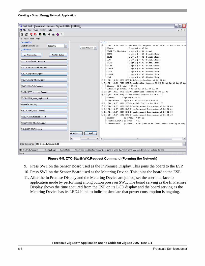
Creating a Smart Energy Network Application
Freescale ZigBee™ Application User’s Guide for ZigBee 2007, Rev. 1.1
6-6 Freescale Semiconductor
Figure 6-5. ZTC-StartNWK.Request Command (Forming the Network)
9. Press SW1 on the Sensor Board used as the InPremise Display. This joins the board to the ESP.10. Press SW1 on the Sensor Board used as the Metering Device. This joins the board to the ESP.11. After the In Premise Display and the Metering Device are joined, set the user interface to
application mode by performing a long button press on SW1. The board serving as the In Premise Display shows the time acquired from the ESP on its LCD display and the board serving as the Metering Device has its LED4 blink to indicate simulate that power consumption is ongoing.

Creating a Smart Energy Network Application
Freescale ZigBee™ Application User’s Guide for ZigBee 2007, Rev. 1.1
Freescale Semiconductor 6-7
Figure 6-6 shows a working Smart Energy Network containing the ESP, an In Premise Display and a Metering Device.
Figure 6-6. Working Smart Energy Network

Creating a Smart Energy Network Application
Freescale ZigBee™ Application User’s Guide for ZigBee 2007, Rev. 1.1
6-8 Freescale Semiconductor
6.3.2 Sending CommandsUse the Test Tool Command Console to send various text information and commands to the display with user confirmation required.
1. From Test Tool Command Console tool bar, click on All Commands -> ZigBee Cluster Library commands and select the ZclMessaging_DisplayMessageReq command.
2. Set the parameters in the Request as follows (also shown in Figure 6-7):— DestAddress — To the address of the InPremiseDisplay (0x0000000000000001)— ClusterID — As the message cluster (0x0703)— MessageControl — To 0x80 (To require a Confirmation)— Choose a desired message length and message text
Figure 6-7. ZclMessaging_DisplayMessageReq Command Configuration
The In Premise Display now shows the message in its LCD display and LED2 blinks to indicate that a Confirmation is required.

Creating a Smart Energy Network Application
Freescale ZigBee™ Application User’s Guide for ZigBee 2007, Rev. 1.1
Freescale Semiconductor 6-9
3. Press SW2 on the In Premise Display board to send a confirmation back to the ESP.
NOTEThe Metering Device does not have mandatory commands that can be used to request consumption information. However, it does use attribute commands. A read attribute command can be sent to the Metering Device to acquire its consumption data.
4. From Test Tool Command Console tool bar, click on All Commands -> ZigBee Cluster Library and select the ReadAttribute request command.
5. Set the parameters in the Request as follows (also shown in Figure 6-8):— DestAddress — To the address of the MeteringDevice (0x000000000000796F)— ClusterID — As the message cluster (0x0702)— Attribute list — To contain the ID of the “CurrentSummationDelivered” attribute (0x000)The response will be received as an Aps-data.Indication.
Figure 6-8. ReadAttribute Request Command Configuration

Creating a Smart Energy Network Application
Freescale ZigBee™ Application User’s Guide for ZigBee 2007, Rev. 1.1
6-10 Freescale Semiconductor
As an option, the Metering Device consumption data can be set to automatically report to the ESP based on a fixed time interval using the Configure reporting command. To obtain an Attribute report, set up a binding on the originator as follows.
1. From Test Tool Command Console tool bar click on All commands -> ZDO Layer commands and choose the ZDP-Bind.Request command.
2. Set the parameters in the Request as follows (also shown in Figure 6-9):— DestAddress — To the short address of the MeteringDevice (0x796F)— SrcAddr — To the IEEE address of the MeteringDevice— ClusterId — As the Simple Meter Cluster ID (0x0702)— DestAddrMode — To 0x03 (IEEE Address)— Destination address — To the IEEE of the ESP(0xAAAAAAAAAAAAAAAA)— Both SrcEndpoint and DstEndpoint to 0x08 (default endpoint of the demo applications)
Figure 6-9. ZDP-Bind.Request Command Configuration

Creating a Smart Energy Network Application
Freescale ZigBee™ Application User’s Guide for ZigBee 2007, Rev. 1.1
Freescale Semiconductor 6-11
Use the Configure Reporting command to configure a report after setting up the binding as follows:1. From Test Tool Command Console tool bar click on All commands -> ZigBee Cluster Library
Commands and select the ConfigureReporting command.2. Set the parameters in the Request as follows (also shown in Figure 6-10):
— DestAddress — To the short address of the MeteringDevice (0x796F)— ClusterId — As the Simple Meter Cluster ID (0x0702)— DestAddrMode — To 0x03 (IEEE Address)— Both SrcEndpoint and DstEndpoint — To 0x08 (default endpoint of the demo applications)— Attribute Id — To contain the Id of the “CurrentSummationDelivered” attribute (0x000)— Attribute data type — To “48 bit unsigned integer”— Direction to 0x00 — To indicate that the report is from the client side to the server side— MinReportingInterval — To 0x000 and the MaxReportingInterval — To 0x0004 (This forces
the Metering Device to send out the attribute every 4 seconds.)— Attribute Lenght — Ro 6 (length of a 48 bit integer)— Reportable Change — To 0x00,0x00,0x00,0x00,0x00,0x00
Figure 6-10. ConfigureReporting Command Configuration

Creating a Smart Energy Network Application
Freescale ZigBee™ Application User’s Guide for ZigBee 2007, Rev. 1.1
6-12 Freescale Semiconductor
The Metering Device now sends out an attribute report every four seconds that simulates meter consumption as shown in Figure 6-11.
Figure 6-11. Metering Device Attribute Reporting
NOTECertain Smart Energy clusters require that APS/Link key security is applied. This is accomplished by setting the TxOptions field to 0x01.

Freescale ZigBee™ Application User’s Guide for ZigBee 2007, Rev. 1.1
Freescale Semiconductor 7-1
Chapter 7 Example ApplicationsBeeStack includes example applications to:
• Enable building a simple network before writing any code• Provide example-quality code for ZigBee applications
7.1 ZigBee Application GlossaryThe following concepts explain a few of the significant elements in a ZigBee network.Cluster A container for one or more attributes in a command structure. If a command
structure does not use attributes (such as the ZigBee Device Profile), each command and response within it is a cluster. Each cluster is identified by an enumeration that is unique within an application profile.
Cluster Identifier An enumeration that uniquely identifies a cluster within an application profile. Cluster identifiers are designated as inputs or outputs in the simple descriptor for use in creating a binding table.
Application Profile An agreement for messages, message formats and processing actions that enable developers to create an interoperable, distributed activity among applications that reside on separate devices. These profiles enable devices to send commands, request data and process commands and requests. For instance, a thermostat on one node can communicate with a furnace on another node. Together, they co-operatively form a heating application profile. A profile can be public, such as the Home Automation profile, so that many vendors can independently build ZigBee nodes that will interoperate. Or a profile can be private, so that a vendor can add proprietary features instead of or in addition to one or more public profiles.
Profile ID The 16-bit number that identifies an application profile. Each unique profile must have a unique profile ID. The ZigBee Alliance issues profile IDs. Every data message and acknowledgement contains the ID of the profile that generated it. ZigBee nodes use this ID as a filter so they can discard any messages for a profile that the receiving node does not implement.
Group An associated set of ZigBee nodes. Group addressing allows any node to send a message to all members of a group and to no other node. This allows a set of nodes to act together.
Scene A stored set of configuration values that an incoming message can invoke, such as a light level on a dimmable lamp. Scenes work naturally in groups, so that a single

Example Applications
Freescale ZigBee™ Application User’s Guide for ZigBee 2007, Rev. 1.1
7-2 Freescale Semiconductor
command can configure any number of related nodes for a particular purpose, such as configuring a media room for watching video.
7.2 Example Application User InterfacesAlmost all of the Freescale ZigBee development boards have four LEDs (LED1-LED4) and four push-buttons (SW1-SW4). The example applications run on any of the boards. The MC1322x Network Node, MC1321x-NCB and 1320x-QE128EVB also have an LCD screen in addition to the LEDs. All the example applications display status and command information on the LCD in addition to the four LEDs. On every board, the push-buttons and LEDs are in single rows. LED1 is above SW1, LED2 is above SW2, and so on.
NOTEReferring to switches SW1-SW4 in this chapter refers to the four push-buttons present on most of the Freescale development boards. For example, on the 1320x-QE128EVB, the four buttons are actually labeled SW2-SW5 and on the SARD they are labeled S101-S104.
If using the MC1322x-LPN board, only two buttons and two leds are available. Restrictions and changes related to this board are mentioned in the corresponding steps if needed. See Section 2.1.1, “HCS08 MCU Board Details” for more information.
7.3 Application Support Library (ASL) KeysMost of the application use a library of common routines referred to as the Application Support Library (ASL). These routines include all of the common user interface elements of the applications, including the concept of two keyboard modes (configuration mode and run-mode), and a common set of keys that map to specific ZigBee functions.
All the example applications use the same keys to cause any activity that they all can do, such as join or leave a network. This section describes the key presses that are common to all the example applications.
The included key driver can read a long (approximately one second) keypress and a short (less than one second) keypress from each of the four keys. The example applications take advantage of this to support up to eight user-initiated events in each mode. The keypress interpretation is entirely in the application code; the applications can be rewritten to do anything.
The applications have the following two modes:• Configuration• Run
The applications always start in configuration mode, where key presses cause the network formation and setup. When that is done, another key press takes the application to run mode, where it can do whatever the application is designed to do, such as turn a light on or off remotely, report data, etc.

Example Applications
Freescale ZigBee™ Application User’s Guide for ZigBee 2007, Rev. 1.1
Freescale Semiconductor 7-3
7.3.1 ASL Configuration ModeShort push button presses do the following:
• SW1 – Form/join network (form if ZC, join if ZR or ZED) with previous configuration• SW2 – Toggle permit join (ZC/ZR) or toggle low power mode (ZED)• SW3 – End device bind/match• SW4 – Change radio channel: each press steps to the next higher channel and briefly displays a
channel indicator on all four LEDs: 0000 is channel 11, 1111 is channel 26
Long push button presses do the following:• Long SW1 – Go to run mode• Long SW2 – Leave the network• Long SW3 – Remove all bindings• Long SW4 – Form/join network (form if ZC, join if ZR or ZED) with new configuration
7.3.2 Run ModeShort push button presses do the following:
• SW1 – This does the main action of the application: toggle a light, etc.• SW2 – • SW3 – Toggle identify mode• SW4 – Recall scene
Long push button presses do the following:• Long SW1 – Go to configuration mode• Long SW2 – • Long SW3 – Send “Add group if in Identify mode” command• Long SW4 – Send “Store scene if in Identify mode” command
7.4 Application Support Library (ASL) LEDs and DisplayMost of the application use a library of common routines referred to as the Application Support Library (ASL). These routines include all of the common user interface elements of the applications, including keeping track of two displays, one for configuration mode and one for run mode. These two displays affect both the LEDs and the LCD display.
The LEDs on each board serve a variety of roles defined by a given application. Each LED can be used to indicate a variety of states, depending on whether it is on or off, flashes once or continuously, or serves as an indicator of what other LEDs are doing at the same time. This allows four LEDs to provide a wide array of information and offers the developer many choices for application testing.

Example Applications
Freescale ZigBee™ Application User’s Guide for ZigBee 2007, Rev. 1.1
7-4 Freescale Semiconductor
7.4.1 Configuration Mode
When SW4 is pressed, the example applications change the channel to the next higher one and display a pattern on all four LEDs (Table 7-2) for one second before returning to the previous display pattern.
Table 7-1. Configuration Mode LED Status
Internal State LED1 LED2 LED3 LED4
Idle (not in a network, not joining) Flashing Off Off Off
Forming (ZC) or joining a network All four LEDs in a flash sequence
Network formed (ZC) On On Off Off
Network joined (ZR or ZED) On Off Off Off
Permit join toggle (ZC or ZR) On/Off
End device bind request: find a bind partner Flash
End device bind success On
End device bind failure Off
Low power ZED in light sleep Off On Off Off
Low power ZED in deep sleep Off Off Off On
Table 7-2. Channel to LED State
Channel Number LED1 LED2 LED3 LED4
11 Off Off Off Off
12 Off Off Off On
13 Off Off On Off
14 Off Off On On
15 Off On Off Off
16 Off On Off On
17 Off On On Off
18 Off On On On
19 On Off Off Off
20 On Off Off On
21 On Off On Off
22 On Off On On
23 On On Off Off
24 On On Off On
25 On On On Off
26 On On On On

Example Applications
Freescale ZigBee™ Application User’s Guide for ZigBee 2007, Rev. 1.1
Freescale Semiconductor 7-5
7.4.2 Run ModeIn run mode, if the node is acting as a light, one or more of the LEDs acts as the light, but that behavior is specific to the individual application, so it is described later in this section. The LED behavior across all example applications is shown in Table 7-3.
7.5 Application Support Library (ASL) Specific Configuration for MC1322x-LPN
The MC1322x Low Power Node (MC1322x-LPN) only has two switches and two LEDs. This imposes a series of changes and restrictions to the ASL functionality for switches and LEDs as already described. This section describes the switch and LED functionality for the Low Power Node.
7.5.1 Switches in Configuration ModeShort push button presses do the following:
• SW1 – Form/join network (form if ZC, join if ZR or ZED) with previous configuration• SW2 – End device bind/match (not available during Low Power Mode)
Long push button presses do the following:• Long SW1 – Go to run mode• Long SW2 – Leave the network (not available during Low Power Mode)
Permit join toggle, clear bindings, change radio channel, form/join with new configuration are not available using the switches for the MC1322x Low Power Node.
7.5.2 Switches in Run ModeShort push button presses do the following:
• SW1 – This does the main action of the application: toggle a light, etc.• SW2 – Application Specific (not available during Low Power Mode)
Long push button presses do the following:• Long SW1 – Go to configuration mode• Long SW2 – Application Specific (not available during Low Power mode)
Table 7-3. Run Mode LED Behavior (All Example Applications)
Internal State LED1 LED2 LED3 LED4
Normal application display Off Off Off Off
Add group Blink
Store scene On
Identify mode Flash
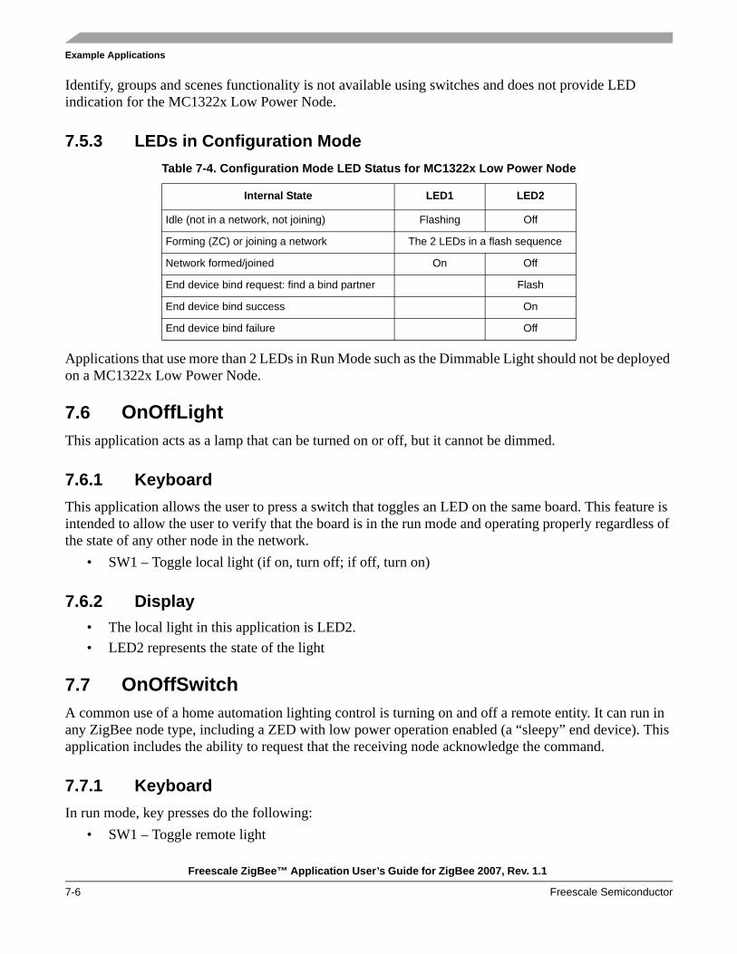
Example Applications
Freescale ZigBee™ Application User’s Guide for ZigBee 2007, Rev. 1.1
7-6 Freescale Semiconductor
Identify, groups and scenes functionality is not available using switches and does not provide LED indication for the MC1322x Low Power Node.
7.5.3 LEDs in Configuration Mode
Applications that use more than 2 LEDs in Run Mode such as the Dimmable Light should not be deployed on a MC1322x Low Power Node.
7.6 OnOffLightThis application acts as a lamp that can be turned on or off, but it cannot be dimmed.
7.6.1 KeyboardThis application allows the user to press a switch that toggles an LED on the same board. This feature is intended to allow the user to verify that the board is in the run mode and operating properly regardless of the state of any other node in the network.
• SW1 – Toggle local light (if on, turn off; if off, turn on)
7.6.2 Display• The local light in this application is LED2. • LED2 represents the state of the light
7.7 OnOffSwitchA common use of a home automation lighting control is turning on and off a remote entity. It can run in any ZigBee node type, including a ZED with low power operation enabled (a “sleepy” end device). This application includes the ability to request that the receiving node acknowledge the command.
7.7.1 KeyboardIn run mode, key presses do the following:
• SW1 – Toggle remote light
Table 7-4. Configuration Mode LED Status for MC1322x Low Power Node
Internal State LED1 LED2
Idle (not in a network, not joining) Flashing Off
Forming (ZC) or joining a network The 2 LEDs in a flash sequence
Network formed/joined On Off
End device bind request: find a bind partner Flash
End device bind success On
End device bind failure Off

Example Applications
Freescale ZigBee™ Application User’s Guide for ZigBee 2007, Rev. 1.1
Freescale Semiconductor 7-7
• SW2 – Turn on remote light with acknowledgement• Long SW2 – Turn off remote light with acknowledgement
7.7.2 DisplayThe LEDs in run mode do this.
• LED2 – Toggles with each toggle command (this can get out of synchronization with the remote light because the remote light’s state can also be changed by other methods)
• LED2 on – Sent On Light Command with acknowledge• LED2 off – Sent Off Light Command with acknowledge
7.8 Dimmable LightThe dimmable light application uses LED2-LED4 to represent a light with four states.
7.8.1 Keyboard• SW1 – Decrease local light’s level• SW2 – Increase local light’s level• Long SW2 – Toggle local light on/off
7.8.2 DisplayOnce in run mode, the dimmable light control configuration makes the following LED assignments to indicate low through high lighting intensity.
• All LEDs off – Light off• LED2 on – Low light intensity• LED2 and LED3 on – Medium light intensity• LED2, LED3 and LED4 on – Maximum light intensity
The LCD display on the MC1322x Network Node shows the light intensity as a percentage and a histogram.
7.9 Dimmer Control Switch This controls the dimmable light.
7.9.1 Keyboard• SW1 – Decrease level of light• SW2 – Increase level of light• Long SW2 – Toggle light on/off

Example Applications
Freescale ZigBee™ Application User’s Guide for ZigBee 2007, Rev. 1.1
7-8 Freescale Semiconductor
7.9.2 DisplayLED2 toggle – When sending an increase or decrease message to a dimmable light
7.10 ThermostatThis application represents a device to control the temperature on a heating, ventilation, or air conditioning (HVAC) system. The thermostat uses two values of the temperature: a local value: Local Temperature (LT) and a desirable value: Desirable Temperature (DT). The difference between the two values establishes the state of the thermostat. That is, whether it is cooling, heating, or idle. When the LT is below the DT by a few degrees, the thermostat will be in heating mode (HeatOn). When DT is greater than the LT, the thermostat will be in cooling mode (CoolOn). When the two values are close, the thermostat is idle. The exact limits that set the mode are stored internally using the OccupiedCoolingSetpoint and OccupiedHeatingSetpoint attributes that are computed based on the value set externally for the DT. When the Thermostat is bound with a temperature sensor that is configured to report the sensed temperature, the thermostat will receive notifications from the other device and will update the LT to the value received from the sensor.
7.10.1 Keyboard• SW1 – Decrease Desirable Temperature• SW2 – Increase Desirable Temperature• Long SW2 – Toggle (oF / oC)
7.10.2 Display• LED2 flashing – LT is below -5oC• All LEDs Off – LT is between -5oC and 10oC• LED2 On, LED3 and LED4 Off – LT is between 10oC and 20oC• LED2 and LED3 On, LED4 Off – LT is between 20oC and 30oC• LED2, LED3 and LED4 On – LT is between 30oC and 40oC• LED2, LED3 On and LED4 Flashing – LT is above 40oC• While changing the DT using the switches, the state of the LEDs as specified above will reflect the
value of DT until LT is updated again• LCD “LT=temp oF / oC” - When LT acquired from the temperature sensor is between the
OccupiedCoolingSetpoint and OccupiedHeatingSetpoint.• LCD “LT=temp oF / oC HeatOn” - When LT acquired from the temperature sensor is lower than
the OccupiedHeatingSetpoint.• LCD - “LT=temp oF / oC CoolOn” - When LT acquired from the temperature sensor is higher than
the OccupiedCoolingSetpoint.• LCD - “DT=temp oF / oC” – When changing the Desirable Temperature.• The LCD display on the MC1322x Network Node displays various icons depending on the action
being performed. For example, a fan icon appears for the thermostat, a snow flake icon appears
Example Applications
Freescale ZigBee™ Application User’s Guide for ZigBee 2007, Rev. 1.1
Freescale Semiconductor 7-9
when the cooling mode is on, a sun icon appears when the heating mode is on and a fan intensity icon appears for the fan cluster values.
7.11 Temperature SensorThe temperature sensor application uses the hardware temperature sensor found on the MC1321x-SRB boards or a simulated temperature value when the application runs on the other boards or the hardware sensor is disabled. Users should note that the temperature reported by the hardware sensor can be slightly different than the actual room temperature.
The Temperature Sensor can send its temperature value using indirect mode, that is, using the local binding table. It typically sends this data when another node has requested that the Temperature Sensor enter reporting mode using the ZigBee Cluster Library (ZCL) report attribute command or when the sensor is indicated to report using a Long SW2 press.
Use SW3 End Device Bind or the Configuration Tool application to bind the Temperature Sensor to a Thermostat, so that the Thermostat can receive temperature reports from the Sensor.
7.11.1 Keyboard• SW1 – Decrease simulated temperature when hardware sensor is not used• SW2 – Increase simulated temperature when hardware sensor is not used• Long SW2 – Turn the Report Temperature On, and begins sending the temperature using indirect
transmission (reports are sent to the devices to which the sensor is bound).
7.11.2 Display• LED1 flashing – sensor is sending OTA temperature reports to bound devices• LED2 flashing – sensed temperature is below -5oC• LED2, LED3, LED4 Off – sensed temperature is between -5oC and 10oC• LED2 On, LED3, LED4 Off – sensed temperature is between 10oC and 20oC• LED2 and LED3 On, LED4 Off– sensed temperature is between 20oC and 30oC• LED2, LED3 and LED4 On – sensed temperature is between 30oC and 40oC• LED2, LED3 On and LED4 Flashing – sensed temperature is above 40oC
7.12 HA Generic ApplicationThe generic application is a device with no unique features. It uses only the common user interface.
7.13 HA Range ExtenderThe range extender is a router with no unique features. It uses only the common user interface.

Example Applications
Freescale ZigBee™ Application User’s Guide for ZigBee 2007, Rev. 1.1
7-10 Freescale Semiconductor
7.14 HA Combined InterfaceThe Combined Interface application acts as a gateway between a personal computer and the ZigBee network by using the ZTC library for UART communication. The run mode of the application does not include any functionality except the “Go to configuration mode” which is enabled by a long press of SW1 of the evaluation board. The behavior of the switches and LEDs in Configuration mode is the same as all other Home Automation applications as shown in Section 7.3.1, “ASL Configuration Mode” and Section 7.4.1, “Configuration Mode”.
7.15 Energy Service Portal (ESP)The Energy Service Portal (ESP) acts as a gateway to a ZigBee network and optionally acts as a Metering Device. It connects the energy supply company network to the metering and energy management devices within the home. It is assumed that a HOST (usually a PC) will relay the messages from the utility company to the ZigBee network. The ESP only routes the messages to the devices from the network. That is, the HOST must keep track of what messages are sent and must ensure that the messages have the correct parameters. The ESP is a ZigBee Coordinator that maintains a list of registered Smart Energy devices (to have secure communications), and also can send inter-pan messages to non-Smart Energy devices.
For the ESP demonstration application, users should employ the Test Tool software as a HOST to relay commands or messages to and from the ZigBee devices. The application run mode does not include any functionality except the “Go to configuration mode” (SW1 - long press), and toggle identify mode (SW3 - short press).
The configuration running mode has all the functionality as shown in Section 7.3.1, “ASL Configuration Mode” and Section 7.4.1, “Configuration Mode” without end device bind/match (SW3 short press) and remove all bindings (SW3 – long press).
7.16 Metering DeviceThe Metering Device demonstration application uses a timer based scheme to demonstrate continuous energy consumption so that the metering data read through the read attribute or through reporting, shows an increasing consumption. For example, the Current Summation Delivered attribute will increment with a random value (between 0 and 32) every 2.5 minutes. The Attribute value can be reported, read to/from the ESP, which provides information to the utility company. The metering device is typically a “sleepy” end device, configured by the ESP to report the metering data. The Metering Device demonstration application shows how an attribute can be “decoupled” and updated asynchronously. It decouples the Current Summation Delivered attribute so that read attribute responses or attribute reports can be sent later. For example, a real meter is read through a slow serial interface.
The configuration running mode has all the functionality as shown in Section 7.3.1, “ASL Configuration Mode” and Section 7.4.1, “Configuration Mode” without end device bind/match (SW3 short press) and remove all bindings (SW3 – long press).
7.16.1 KeyboardIn application run mode, key presses do the following:

Example Applications
Freescale ZigBee™ Application User’s Guide for ZigBee 2007, Rev. 1.1
Freescale Semiconductor 7-11
• SW2 - Toggle the status attribute bit “Check Meter”• SW4 - Toggle on and off energy consumption
7.16.2 DisplayThe LEDs in run application mode do this:
• LED2 - Toggles with each toggle command on SW2• LED4 – Flashing when consumption is On
7.17 In-Premise DisplayThe In-Premise Display demonstration application relays the data to users using a text display. The display shows simple text messages or pricing information to inform users about the utility company actions or current pricing information. The time is updated in the Smart Energy network by the utility company through the ESP and is displayed for all received messages. The In-Premise Display device is typically a ZigBee router that can receive information delivered through the ESP and make it available to users.
The configuration running mode has all the functionality as shown in Section 7.3.1, “ASL Configuration Mode” and Section 7.4.1, “Configuration Mode” without end device bind/match (SW3 short press) and remove all bindings (SW3 – long press).
7.17.1 KeyboardIn application run mode, key presses do the following
• SW2 – Confirm a received messages (if a message needs to be confirmed)• Long SW2 – Send a “Get Last Message Request”• Long SW3 – Send a “Get Current Price Request”• SW4 – Run through information fields of the current price
7.17.2 DisplayThe LEDs in run application mode do this:
• LED2 - Flashing when a received message need to be confirmed • LCD line1 – “InPremiseDisplay” – display application name• LCD line 2-3 – display messages received from the ESP • LCD line 4 – ” PriceTier 1” – display some information fields of the current price; pressing SW4
user can run trough other fields. • LCD line 5 – “PriceStarted” – display price status (received, started, updated, completed, no
current price available) • LCD line 6 – “Time= 07:55:20” – display the current time

Example Applications
Freescale ZigBee™ Application User’s Guide for ZigBee 2007, Rev. 1.1
7-12 Freescale Semiconductor
7.18 Programmable Communicating Thermostat (PCT)The Programmable Communicating Thermostat (PCT) demonstration application shows how received Demand Response and Load Control values are managed by a device that supports load control. LED3 turns on or off when the device is On or Off to represent the duty cycle events. LED4 flashes during the entire Load Control event duration. If a display is connected to the board, information such as event duration, event duty cycle, event status (started, superseded, canceled, completed etc.) is displayed. The load control commands are sent to the PCT device from a HOST CPU or the Test Tool software through the ESP device using serial communication. This allows users to experiment with the Smart Energy Load Control commands.
The configuration running mode has all the functionality as shown in Section 7.3.1, “ASL Configuration Mode” and Section 7.4.1, “Configuration Mode” without end device bind/match (SW3 short press) and remove all bindings (SW3 – long press).
7.18.1 KeyboardIn application run mode, key presses do the following:
• SW1 – Toggle on/off accepting voluntary load control events• SW2 – Send "Opt Out" Load Control Status for last received event• SW3 – Send "Opt In" Load Control Status for last received event
7.18.2 DisplayThe LEDs in run application mode do this:
• LED3 – On (device is On), Off (device is Off). The Duty Cycle gives the "ON Duration" for entire "Load Control Duration" in minutes but LED3 shows the On duration for one minute (Off state precede the On state)
• LED4 – Flashing during the entire Load Control event duration• LCD – “SePCT” – display application name• LCD – “Ev 0010Min 80%ON” – shows that the device will be in “on state” for 80% of the time
for the duration of the event (10 minutes); when the event is received and stared, LED3 is in “On state” for 80% of one minute(48 seconds) for 10 minutes (first state being “Off state”)
• LCD – ”Started” – display the status of the event • LCD – “Time= 07:55:20” – display the current time
7.19 Range ExtenderThe Range Extender is a simple device that acts as a router for other devices from the network. It has no functionality in the application mode The configuration running mode has all the functionality as shown in Section 7.3.1, “ASL Configuration Mode” and Section 7.4.1, “Configuration Mode” without end device bind/match (SW3 short press) and remove all bindings (SW3 – long press).

Example Applications
Freescale ZigBee™ Application User’s Guide for ZigBee 2007, Rev. 1.1
Freescale Semiconductor 7-13
7.20 Load Control, Smart Appliance, Prepayment TerminalThe Load Control, Smart Appliance, Prepayment Terminal are sample applications that have no functionality in the run mode of the application. The configuration running mode has all the functionality as shown in Section 7.3.1, “ASL Configuration Mode” and Section 7.4.1, “Configuration Mode” without end device bind/match (SW3 short press) and remove all bindings (SW3 – long press).
7.21 Manufacturer Specific ApplicationsThe Wireless UART and Accelerometer applications are example applications that are not part of the Home Automation Application Profile. They are also not part of any other ZigBee public profile and are considered to be custom application profiles. The ZigBee Alliance calls these “Manufacturer Specific” applications. These applications are only intended to operate among devices from a single primary manufacturer. Other manufacturers can use these applications, if they have permission to do so, from the primary manufacturer.
7.21.1 Manufacturer Specific Configuration Mode User InterfaceThe following Configuration Mode User Interface is slightly different from the Home Automation applications.
Short push button presses do the following:• SW1 – Form/join network (form if ZC, join if ZR or ZED)• SW2 – Leave network• SW3 – End-device-bind (bind/unbind toggle with another node) / Match• SW4 – Choose channel, walks through all channels (uses 4 LEDs for a binary number 0- 15 which
equates to channels 11-26)
Long (greater than 1 second) push button presses do the following:• Long SW1 – Go to Run Mode• Long SW2 – Toggle Permit Join• Long SW3 – Unbind all• Long SW4 – Reset node to factory defaults

Example Applications
Freescale ZigBee™ Application User’s Guide for ZigBee 2007, Rev. 1.1
7-14 Freescale Semiconductor
7.22 Wireless UARTThe Wireless UART can replace a serial cable with two or more ZigBee nodes. It can multi-hop for extended range using mesh routing. ZigBee is half-duplex and generally low data rate, so it is not applicable for all serial applications.
7.22.1 KeyboardThis application uses the standard ASL user interface, with a few exceptions. Since the Wireless UART does not have scenes or identify mode, SW3, SW4, and Long SW4 do not perform the same functions that they perform in most other applications.
This wireless UART application can replace a wire, and it supports HW flow control to make sure it does not miss messages. Flow control is only supported in one direction; the ZigBee node will assert flow control to tell the PC to stop transmitting. The ZigBee node does not recognize flow control asserted by the PC.
The Wireless UART application can be char or block mode, and/or in loop back mode.
In char mode, every character that is received from the UART is immediately sent to the remote node. This is intended for keyboards and other, similar applications.
In block mode, bytes from the UART are gathered together and sent as a block to the far end. This mode makes more efficient use of the available radio bandwidth (more bytes of payload transferred per ZigBee packet), and is intended for file transfers.
In loopback mode, every byte received from the UART is sent back out the UART. No data from the UART is sent over the air.
• SW1 – Toggle char vs. block mode• SW2 – Toggle loopback mode on/off• SW3 – Not used• SW4 – Toggle through baud rates 1200,2400,4800,9600,19200,38400
• Long SW1 – Go to Configuration Mode• Long SW2 – Not used• Long SW3 – Add Group• Long SW4 – Not Used
7.22.2 DisplayThe LEDs in application mode will display as follows:
• LED1 – on when in char mode, off when in block mode• LED2 – on when in loopback mode, off otherwise• LED3 – toggles on each packet sent to the remote node• LED4 – toggles on each packet sent to the PC via the UART

Example Applications
Freescale ZigBee™ Application User’s Guide for ZigBee 2007, Rev. 1.1
Freescale Semiconductor 7-15
• LCD (on NCB) indicates # of packets transferred• line LCD 1: “Rx 1234 Tx 1234” (in hex)• Line 2 on LCD will not be changed as this is used for the standard ASL interface.
7.22.3 Baud Rate Display User Interface
7.22.3.1 Application ModeEach time SW4 is pressed to change baud rates, the LEDs will change for a moment to display the new baud rate as shown in the following table:
The default baud rate is 38400. The serial port is always set to 8N1:• Eight data bits• No parity• One stop bit
7.23 Generic AppThe Generic App application measures and displays movement of a board in three axis using the built-in accelerometer in the SRB and SARD boards, and shows this movement by lighting LEDs on another display board. Use SW3 to find the other board so that the display of movement takes place on the remote board instead of the local board.
The purpose of the Generic App (also called Accelerometer) application is to:• Show how to interact with BeeStack 2006 without using the ASL interface• Demonstrate a very simple application as a starting point for custom applications• Show how to interact with hardware in the multi-tasking BeeStack environment
The Generic App application does not use the ASL interface. Instead, it blinks LED1 to indicate that it is not on the network when it first starts. When button 1 is pressed, it forms the network as a ZigBee Coordinator (ZC), or it joins a network as a ZigBee Router (ZR) or a ZigBee End Device (ZED). It does NOT have the application vs. configure mode like the ASL does, but instead uses the LED and keyboard routines directly from the driver. It also does not use the NVM interface. When not on hold, the accelerometer transmits once every 500 milliseconds to the remote display.
Table 7-5. Baud Rate LED Display
Baud Rate LED1 LED2 LED3
1200 On Off Off
2400 Off On Off
2400 On On Off
9600 Off Off On
19200 On Off On
38400 Off On On

Example Applications
Freescale ZigBee™ Application User’s Guide for ZigBee 2007, Rev. 1.1
7-16 Freescale Semiconductor
NOTEProgram the Generic App application into two boards. One board will be the accelerometer and the other board will be the remote display. Only press SW3 on the board that will be the accelerometer. The other board, without any key presses, will then be the display for the accelerometer.
7.23.1 KeyboardIn run mode, key presses do the following:
• SW1 – join/form the network• SW2 – Walks through 5 tilt states (all LEDS off, 1 -4 on). SARD and SRB boards ignore this button
and use actual accelerometer hardware.• LSW2 – Toggles “hold” (starts/stops detecting and transmitting accelerometer data). “hold” is the
default state when the board boots.• SW3 – Find accelerometer display using match descriptor (LED3 will light on both boards)• SW4 – Toggles through display axis (X, Y or Z). On NCB, all axes are displayed on LCD, but only
1 axis on LEDs. Will briefly display LED1=X, LED2=Y, LED3=Z to indicate which axis will be displayed on the LEDs.
7.23.2 DisplayThe LEDs in run mode do the following:
• LED1 blinks when not on network. • LED1 is solid when joined/formed the network.• LED3 is solid on when display is found.• LEDs 1-4 indicate 5 states of tilt for the currently displayed access (0 to 4 LEDs on). All LEDs off
means upside down on Z-axis. All LEDs on means right side up on Z-axis.